EP3632332A1 - Suivi d'un dispositif d'intervention de poursuite par rapport à un plan d'image ultrasonore - Google Patents
Suivi d'un dispositif d'intervention de poursuite par rapport à un plan d'image ultrasonore Download PDFInfo
- Publication number
- EP3632332A1 EP3632332A1 EP18198801.5A EP18198801A EP3632332A1 EP 3632332 A1 EP3632332 A1 EP 3632332A1 EP 18198801 A EP18198801 A EP 18198801A EP 3632332 A1 EP3632332 A1 EP 3632332A1
- Authority
- EP
- European Patent Office
- Prior art keywords
- ultrasound
- icon
- smax
- plane
- interventional device
- Prior art date
- Legal status (The legal status is an assumption and is not a legal conclusion. Google has not performed a legal analysis and makes no representation as to the accuracy of the status listed.)
- Withdrawn
Links
Images


Classifications
-
- A—HUMAN NECESSITIES
- A61—MEDICAL OR VETERINARY SCIENCE; HYGIENE
- A61B—DIAGNOSIS; SURGERY; IDENTIFICATION
- A61B8/00—Diagnosis using ultrasonic, sonic or infrasonic waves
- A61B8/08—Detecting organic movements or changes, e.g. tumours, cysts, swellings
- A61B8/0833—Detecting organic movements or changes, e.g. tumours, cysts, swellings involving detecting or locating foreign bodies or organic structures
- A61B8/0841—Detecting organic movements or changes, e.g. tumours, cysts, swellings involving detecting or locating foreign bodies or organic structures for locating instruments
-
- A—HUMAN NECESSITIES
- A61—MEDICAL OR VETERINARY SCIENCE; HYGIENE
- A61B—DIAGNOSIS; SURGERY; IDENTIFICATION
- A61B8/00—Diagnosis using ultrasonic, sonic or infrasonic waves
- A61B8/12—Diagnosis using ultrasonic, sonic or infrasonic waves in body cavities or body tracts, e.g. by using catheters
-
- A—HUMAN NECESSITIES
- A61—MEDICAL OR VETERINARY SCIENCE; HYGIENE
- A61B—DIAGNOSIS; SURGERY; IDENTIFICATION
- A61B8/00—Diagnosis using ultrasonic, sonic or infrasonic waves
- A61B8/44—Constructional features of the ultrasonic, sonic or infrasonic diagnostic device
- A61B8/4477—Constructional features of the ultrasonic, sonic or infrasonic diagnostic device using several separate ultrasound transducers or probes
-
- A—HUMAN NECESSITIES
- A61—MEDICAL OR VETERINARY SCIENCE; HYGIENE
- A61B—DIAGNOSIS; SURGERY; IDENTIFICATION
- A61B8/00—Diagnosis using ultrasonic, sonic or infrasonic waves
- A61B8/44—Constructional features of the ultrasonic, sonic or infrasonic diagnostic device
- A61B8/4483—Constructional features of the ultrasonic, sonic or infrasonic diagnostic device characterised by features of the ultrasound transducer
-
- A—HUMAN NECESSITIES
- A61—MEDICAL OR VETERINARY SCIENCE; HYGIENE
- A61B—DIAGNOSIS; SURGERY; IDENTIFICATION
- A61B8/00—Diagnosis using ultrasonic, sonic or infrasonic waves
- A61B8/52—Devices using data or image processing specially adapted for diagnosis using ultrasonic, sonic or infrasonic waves
- A61B8/5207—Devices using data or image processing specially adapted for diagnosis using ultrasonic, sonic or infrasonic waves involving processing of raw data to produce diagnostic data, e.g. for generating an image
-
- A—HUMAN NECESSITIES
- A61—MEDICAL OR VETERINARY SCIENCE; HYGIENE
- A61B—DIAGNOSIS; SURGERY; IDENTIFICATION
- A61B17/00—Surgical instruments, devices or methods, e.g. tourniquets
- A61B17/34—Trocars; Puncturing needles
- A61B17/3403—Needle locating or guiding means
- A61B2017/3413—Needle locating or guiding means guided by ultrasound
-
- A—HUMAN NECESSITIES
- A61—MEDICAL OR VETERINARY SCIENCE; HYGIENE
- A61B—DIAGNOSIS; SURGERY; IDENTIFICATION
- A61B8/00—Diagnosis using ultrasonic, sonic or infrasonic waves
- A61B8/42—Details of probe positioning or probe attachment to the patient
- A61B8/4245—Details of probe positioning or probe attachment to the patient involving determining the position of the probe, e.g. with respect to an external reference frame or to the patient
Definitions
- the invention relates to determining a position of an interventional device respective an image plane of a beamforming ultrasound imaging probe.
- Interventional devices such as medical needles, catheters and surgical tools are often difficult to visualize in an ultrasound image due to the specular nature of their reflectivity, particularly at unfavorable incidence angles.
- document WO2018060499A1 describes a system for indicating a position of an interventional device feature of an interventional device respective an image plane defined by an ultrasound imaging probe of a beamforming ultrasound imaging system in which the position of the interventional device feature is determined based on ultrasound signals transmitted between the ultrasound imaging probe and an ultrasound transducer attached to the interventional device at a predetermined distance from the interventional device feature.
- An icon providing unit provides a first icon indicative of a circular zone with a radius corresponding to the predetermined distance. The first icon is displayed in a fused image that includes a reconstructed ultrasound image from the beamforming ultrasound imaging system.
- an out-of-plane distance is computed based on a model of the variation in signal intensity with out-of-plane distance D op for the determined range.
- a system for determining a position of an interventional device respective an image plane defined by an ultrasound imaging probe of a beamforming ultrasound imaging system in which the position of the interventional device is determined based on ultrasound signals transmitted between the ultrasound imaging probe and an ultrasound transducer attached to the interventional device.
- the system includes an image reconstruction unit and a position determination unit.
- the image reconstruction unit provides a reconstructed ultrasound image corresponding to an image plane defined by the ultrasound imaging probe.
- the position determination unit computes a lateral position of the ultrasound transducer respective the image plane based on a time of flight of a maximum detected intensity ultrasound signal transmitted between the ultrasound imaging probe and the ultrasound transducer.
- the position determination unit also computes an out-of-plane distance between the ultrasound transducer and the image plane, based on the intensity and the time of flight of the maximum detected intensity ultrasound signal.
- Computing the out-of-plane distance includes comparing the maximum detected intensity with a model describing an expected variation of in-plane maximum detected intensity with time of flight, at the time of flight of the maximum detected intensity ultrasound signal.
- the position determination unit subsequently indicates the out-of-plane distance in the reconstructed ultrasound image.
- the model used in computing the out-of-plane distance thus describes an expected variation of in-plane maximum detected intensity with time of flight.
- the in-plane detected intensity may exhibit low variability between different ultrasound imaging probes and thus the same model may be used for ultrasound imaging probes of the same type.
- this model requires only one-dimensional calibration data; i.e. a variation in the intensity with time of flight, and this requires only a limited amount of calibration data.
- in-use the out-of-plane distance may be determined with low latency due to the need to search in only one, i.e. the time of flight, dimension.
- indicating the out-of-plane distance includes providing a first icon at the computed lateral position, the first icon being indicative of a circular zone with a radius corresponding to the out-of-plane distance.
- the use of an icon at the computed position with a circular zone indicative of the out-of-plane distance indicates intuitively to a user whether the interventional device is being advanced towards or away-from the image plane based on whether the circle grows or shrinks. This allows for improved guidance of the interventional device.
- the radius corresponding to the out of plane distance is determined based on scaling the maximum detected intensity to the expected in-plane maximum detected intensity, at the time of flight of the maximum detected intensity ultrasound signal.
- the maximum detected intensity typically reduces as the out-of-plane distance D op is increased.
- the nature of this variation with out-of-plane distance may depend upon the time of flight; in other words the range between the ultrasound imaging probe and the ultrasound detector. Determining the radius based on scaling the maximum detected intensity to the expected in-plane maximum detected intensity results in a qualitative indication of the out-of-plane distance.
- Such an indication provides adequate feedback for a user to accurately navigate the interventional device to the image plane, and obviates the need for full three-dimensional calibration data that might otherwise be required to determine an exact out-of-plane distance, as well as the latency associated with searching such three-dimensional data to determine the out of-plane distance.
- the first icon includes a perimeter.
- the appearance of the first icon is configured to change based on a comparison of the maximum detected intensity with the expected in-plane maximum detected intensity, at the time of flight of the maximum detected intensity ultrasound signal, if i) a ratio of the maximum detected intensity to the expected in-plane maximum detected intensity, at the time of flight of the maximum detected intensity ultrasound signal, or ii) the maximum detected intensity, lies within a predetermined range.
- Changing the appearance of the perimeter has the effect of indicating to a user the position of the interventional device at predetermined positions respective the imaging plane. This feature allows the rapid indication to a user of the general position of the interventional device respective the imaging plane.
- the color of the icon may be green when the maximum detected intensity or its ratio indicates a value close to the expected in-plane maximum detected intensity, and red when for values within an abutting range, and white for positions outside this range. This indicates quickly to a user whether the interventional device is currently in-plane.
- the radius corresponding to the out of plane distance has a minimum value.
- the position determination unit limits the radius to the minimum value if i) a ratio of the maximum detected intensity to the expected in-plane maximum detected intensity, at the time of flight of the maximum detected intensity ultrasound signal, or ii) the maximum detected intensity, exceeds a predetermined value.
- a user is typically interested in positioning the interventional device in the imaging plane; and thus in this implementation the icon may for example change when the icon is within a predetermined range of exactly in the imaging plane. In so doing the user may to some extent relax their concentration when the interventional device is sufficiently well localized. This prevents the user from continually making minute adjustments of the position of the interventional device, allowing them to focus on other tasks.
- the position determination unit suppresses the provision of the first icon in the reconstructed ultrasound image if i) a ratio of the maximum detected intensity to the expected in-plane maximum detected intensity, at the time of flight of the maximum detected intensity ultrasound signal, or ii) the maximum detected intensity, falls below a predetermined value. If either of these parameters fall below the predetermined value the system may be insufficiently sensitive to reliably indicate the position of the interventional device respective the imaging plane. Weakly detected ultrasound signals may be confounded by electromagnetic interference or noise. Under such circumstances it is preferable to suppress the provision of the first icon in the reconstructed ultrasound image in order to avoid indicating a potentially inaccurate position.
- the interventional device includes a feature, such as its distal end.
- the ultrasound transducer is attached to the interventional device at a predetermined distance from the interventional device feature.
- the position determination unit also provides a second icon in the reconstructed ultrasound image, the second icon being indicative of a circular zone with a radius corresponding to the predetermined distance between the ultrasound transducer and the interventional device feature.
- the first icon and the second icon share a common center, i.e. at the computed lateral position.
- the second icon is indicative of a range of possible positions of the feature, e.g. the distal end, of the interventional device.
- Providing both icons in the reconstructed ultrasound image beneficially indicates the position of the feature of the interventional device respective the image plane. Two extreme scenarios are now explained in order to indicate the benefits of providing both icons.
- the interventional device feature and the ultrasound transducer both lie in the image plane.
- the reconstructed ultrasound image includes the first icon which indicates the out-of-plane position and is centered at the position of the ultrasound transducer.
- the first icon indicates, as described above, that the transducer is in the image plane.
- the interventional device feature lies somewhere around the perimeter of the circular zone indicated by the overlapping second icon; this being because the radius of the circular zone corresponds to the predetermined distance between the ultrasound transducer and the interventional device feature.
- the perimeter of the icons indicates the position of the interventional device feature.
- the user Based on the user's progression of the needle and its approximate trajectory, the user will also know approximately which part of the perimeter of the circular zone the distal end of the medical needle is actually located. Moreover the user will be aware of this trajectory from intermittent reconstructed ultrasound images of the shaft of medical needle 11. Thus the user can mentally augment the information provided by the first icon in order to identify more precisely where on the perimeter of the circular zone the interventional device feature lies.
- the interventional device feature lies in the image plane and the ultrasound transducer lies above or below the image plane along a line passing through the feature and normally with respect to the image plane.
- the reconstructed ultrasound image includes the first icon which is centered at the position of the ultrasound transducer as-projected onto the image plane.
- Such a projection can involve i) projecting the position of the ultrasound transducer in a direction that is normal to the image plane, or ii) projecting a range between the ultrasound imaging probe and the ultrasound transducer onto the image plane, or iii) projecting the position of the ultrasound transducer in a direction that is perpendicular to the range between the ultrasound imaging probe and the ultrasound transducer.
- the first icon indicates the out-of-plane distance.
- the center of the second icon indicates the position of the feature, i.e. the distal end, of the interventional device.
- the first and second icons overlap, i.e. they indicate the same distance, the interventional device feature has just reached the image plane.
- interventional device feature lies somewhere between the center of the circular zone indicated by the second icon and the perimeter of its circular zone.
- the interventional device feature is known to be on or within the perimeter of the circular zone defined by the second icon, improved positioning of the interventional device feature respective the image plane is provided. Put another way, a user of the system has confidence that the interventional device feature does not impact image features that lie outside this circular zone.
- the localization can be provided using only a single ultrasound transducer, thereby simplifying manufacture of the interventional device.
- the position determination causes the appearance of at least one of the first icon and the second icon to change when the out-of-plane distance is less than or equal to the predetermined distance. In so doing, during the aforementioned out-of-plane procedure, a user is alerted to the fact that the interventional device feature is in the center of the image plane.
- the radius of the first icon has a minimum value that is equal to the radius of the second icon, and wherein the radius of the first icon is limited to the minimum value when the out-of-plane distance is less than or equal to the predetermined distance.
- an interventional device exemplified by a medical needle
- an image plane defined by a linear array of a 2D ultrasound imaging probe.
- the position of a feature, such as the distal end, of the medical device is also tracked.
- interventional devices such as, and without limitation, a catheter, a guidewire, a probe, an endoscope, an electrode, a robot, a filter device, a balloon device, a stent, a mitral clip, a left atrial appendage closure device, an aortic valve, a pacemaker, an intravenous line, a drainage line, a surgical tool, a tissue sealing device, a tissue cutting device or an implantable device.
- the tracked feature of such interventional devices may exemplarily include a distal end of the interventional device, a biopsy sampling point of the interventional device, a cutting edge of the interventional device, an opening of a channel in the interventional device, a sensor (e.g. for sensing flow, pressure, temperature etc.) of the interventional device, a surgical tool (e.g. a scraper) integrated in the interventional device, a drug delivery point of the interventional device, or an energy delivery point of the interventional device.
- a catheter e.g. for sensing flow
- the exemplified linear array of a 2D ultrasound imaging probe is only one example of an ultrasound transceiver array of a beamforming ultrasound imaging system in which the invention may be used.
- the invention also finds application in other types of beamforming ultrasound imaging systems whose associated ultrasound transceiver arrays exemplarily include a 2D array of a 3D imaging probe (or in bi-plane view), a "TRUS” transrectal ultrasonography probe, an "IVUS" intravascular ultrasound probe, a "TEE” transesophageal probe, a "TTE” transthoracic probe, a “TNE” transnasal probe, an "ICE” intracardiac probe.
- Fig. 1 illustrates a beamforming ultrasound imaging system 14 in combination with an in-plane interventional device 11 and an embodiment of the invention in the form of system 10.
- beamforming ultrasound imaging system 14 includes a 2D ultrasound imaging probe 13 which is in communication with image reconstruction unit IRU, imaging system processor ISP, imaging system interface ISI and display DISP.
- the units IRU, ISP, ISI and DISP are conventionally located in a console that is in wired communication with 2D ultrasound imaging probe 13. It is also contemplated that wireless communication, for example using an optical, infrared, or an RF communication link, may replace the wired link.
- 2D ultrasound imaging probe 13 includes linear ultrasound transceiver array 16 that transmits and receives ultrasound energy within an ultrasound field that intercepts volume of interest VOI.
- the ultrasound field is fan-shaped in Fig. 1 and includes multiple ultrasound beams B 1..k that define image plane 12. Note that a fan-shaped beam is illustrated in Fig. 1 for the purposes of illustration only and that the invention is not limited to a particular shape of ultrasound field.
- Beamforming ultrasound imaging system 14 may also include electronic driver and receiver circuitry, not shown, that is configured to amplify and/ or to adjust the phase of signals transmitted by or received by 2D ultrasound imaging probe 13 in order to generate and detect ultrasound signals in beams B 1..k .
- the electronic driver and receiver circuitry may thus be used to steer the emitted and/ or received ultrasound beam direction.
- beamforming ultrasound imaging system 14 is operated in the following way.
- An operator may plan an ultrasound procedure via imaging system interface ISI.
- imaging system interface ISI triggers imaging system processor ISP to execute application-specific programs that generate and interpret the signals transmitted by and detected by 2D ultrasound imaging probe 13.
- Beamforming ultrasound imaging system 14 may also include a memory (not shown) for storing such programs.
- the memory may for example store ultrasound beam control software that is configured to control the sequence of ultrasound signals transmitted by and/ or received by ultrasound imaging probe 13.
- Image reconstruction unit IRU which may alternatively form part of imaging system processor ISP, reconstructs data received from the ultrasound imaging probe 13 into an image corresponding to image plane 12 and which thus intercepts volume of interest VOI, and subsequently displays this image on display DISP.
- a planar section through volume of interest VOI is termed region of interest ROI herein.
- Reconstructed ultrasound image RUI may thus include region of interest ROI.
- the reconstructed image may for example be an ultrasound Brightness-mode "B-mode” image, otherwise known as a "2D mode” image, a "C-mode” image or a Doppler mode image, or indeed any ultrasound planar image.
- a medical needle 11 as an example of an interventional device, and an embodiment of the invention, system 10, that may be used to indicate a position of interventional device 11, i.e. the medical needle, respective image plane 12 of ultrasound imaging probe 13.
- system 10 includes image reconstruction unit IRU and position determination unit PDU. These units are in communication with one another as illustrated by the interconnecting arrows. It is also contemplated that one or more of units PDU, IRU may be incorporated within a memory or a processor of beamforming ultrasound imaging system 14, for example within a memory or a processor that also provides the functionality of unit ISP.
- Medical needle 11 that is tracked includes ultrasound transducer 15 that may be positioned at predetermined distance L p from distal end 11a of interventional device 11.
- a position of interventional device 11, or more specifically that of ultrasound transducer 15 attached thereto, is computed respective image plane 12 by position determination unit PDU based on ultrasound signals transmitted between ultrasound transceiver array 16 and ultrasound transducer 15.
- ultrasound transducer 15 is a detector that receives ultrasound signals corresponding to beams B 1..k .
- Position determination unit PDU identifies the lateral position LAP of ultrasound transducer 15 respective image plane 12 by correlating; i.e. comparing, the ultrasound signals emitted by ultrasound transceiver array 16 with the ultrasound signals detected by ultrasound transducer 15. More specifically this correlation determines the best fit position of ultrasound transducer 15 respective image plane 12 based on i) the intensities of the ultrasound signals corresponding to each beam B 1..k that are detected by ultrasound transducer 15 and ii) based on the time delay, i.e. time of flight, between emission of each beam B 1..k and its detection by ultrasound transducer 15. This may be illustrated as follows.
- the beam that is detected with the maximum detected intensity is identified as the one that is closest to ultrasound detector 15.
- the maximum detected intensity I Smax ultrasound signal identifies the in-plane angle ⁇ IPA between ultrasound transceiver array 16 and ultrasound transducer 15.
- the time of flight, between the emission of this beam (from beams B 1..k ) and its subsequent detection is indicative of the range between ultrasound transceiver array 16 and ultrasound transducer 15.
- TOF Smax is the ultrasound signal that is selected from the ultrasound signals of all beams. Since the time of flight is indicative of the range, in polar coordinates the lateral position of ultrasound transducer 15 respective image plane 12 may be represented by LAP TOFSmax, ⁇ IPA . If desired, the range may be determined by multiplying the time delay by the speed of ultrasound propagation.
- ultrasound transducer 15 is an emitter that emits one or more ultrasound pulses. Such pulses may for example be emitted during tracking frames that are interleaved between the usual imaging frames of ultrasound imaging system 14. In such a tracking frame the ultrasound transceiver array 16 may be operated in a receive-only mode in which it listens for ultrasound signals originating from the vicinity of image plane 12. Ultrasound transceiver array 16 is thus configured as a one-way receive-only beamformer. Position determination unit PDU identifies from which beam of beams B 1..k the pulse(s) originated based on the ultrasound signals emitted by ultrasound transducer 15 and those detected by ultrasound transceiver array 16.
- position determination unit PDU may use a correlation procedure that, based on the ultrasound signal detected with maximum intensity and its time of flight, identifies the closest beam and thus the point at which the ultrasound signal was emitted, i.e. its lateral position LAP TOFSmax, ⁇ IPA in the same manner.
- a correlation, i.e. comparison, procedure may again be used to determine its best-fit position respective image plane 12 for each tracking frame.
- ultrasound transducer 15 may be configured to act as both a receiver and an emitter, or include both a receiver and an emitter.
- ultrasound transducer 15 may be triggered to emit one or more ultrasound pulses upon receipt of an ultrasound signal from ultrasound transceiver array 16; optionally following a delay that is equal to one or more frame periods of ultrasound imaging system 14.
- the pulse(s) emitted by ultrasound transducer 15 during an imaging mode are received by ultrasound transceiver array 16 in the form of an echo in the reconstructed ultrasound at an in-plane angular position, i.e. in an image line, that corresponds to the triggering beam B 1..k .
- Ultrasound transducer 15 thus appears as a bright spot in the reconstructed image.
- Position determination unit PDU may subsequently identify this bright spot in the reconstructed image and thus again compute a lateral position LAP TOFSmax, ⁇ IPA of ultrasound transducer 15 respective image plane 12.
- ultrasound imaging probe 13 may further include at least three ultrasound emitters that are attached to the ultrasound imaging probe 13.
- the at least three ultrasound emitters are in communication with position determination unit PDU.
- the position determination unit PDU is configured to compute a position of the ultrasound transducer 15 respective the image plane 12 based on ultrasound signals transmitted between the at least three ultrasound emitters attached to the ultrasound imaging probe 13, and the ultrasound transducer 15.
- position determination unit PDU determines a range between each emitter and ultrasound transducer 15 based on the time of flight of ultrasound signals emitted by each emitter. The three dimensional position of ultrasound transducer 15 is subsequently determined using triangulation.
- This provides the position of ultrasound transducer 15 in three dimensions respective ultrasound imaging probe 13, or more specifically respective image plane 12 since the at least three emitters are attached to the ultrasound imaging probe 13.
- the three-dimensional position may subsequently be mapped to image plane 12 and thus again represented by LAP TOFSmax, ⁇ IPA .
- Ultrasound emitters are preferred in this configuration because the supply of high power ultrasound signals to the emitters, necessary for accurate positioning over a large range, is simpler when the emitters are proximate ultrasound imaging probe 13 where a power source is readily available.
- This arrangement is thus preferred in contrast to locating a high power emitter on interventional device 11.
- the lateral position of interventional device 11, or more specifically that of ultrasound transducer 15 attached thereto is thus again computed respective image plane 12 by position determination unit PDU based on ultrasound signals transmitted between the at least three emitters and ultrasound transducer 15.
- position determination unit PDU illustrated in Fig. 1 may be used in any of the above configurations to compute a lateral position of ultrasound transducer 15 respective image plane 12 based on ultrasound signals transmitted between ultrasound imaging probe 13 and ultrasound transducer 15.
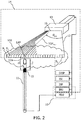
- Fig. 2 illustrates a beamforming ultrasound imaging system 14 in combination with an interventional device 11 disposed at an out-of-plane distance D op and an embodiment of the invention in the form of system 10.
- beams B 1.k of ultrasound imaging probe 13 are illustrated as being in plane 12, this plane has a finite thickness and a reduced ultrasound signal is typically detectable for small out-of-plane displacements. These signals are used in the present invention to estimate the out-of-plane distance D op of ultrasound transducer 15.
- FIG. 3 illustrates a model MO describing an expected variation of in-plane maximum detected intensity, I SmaxInplane (dB) with time of flight, TOF.
- Model MO indicated by the solid curve, illustrates that as the time of flight TOF, i.e. the depth into tissue increases, the in-plane maximum detected intensity, I SmaxInplane , of detected ultrasound signals initially decreases slowly, then more rapidly, and then more slowly again.
- the shape of the model is affected by attenuation of ultrasound signals and may be determined from theoretical calculations or empirical measurements of the in-plane maximum intensity obtained in tissue or corresponding matter.
- Model MO depends only on time of flight and is invariant with in-plane angle ⁇ IPA .
- model MO does not model the maximum detected intensity, I SmaxInplane as a function of out-of-plane distance. Consequently model MO requires only a limited amount of, i.e. one-dimensional, calibration data. In contrast to e.g. a three-dimensional model, in-use the out-of-plane distance may be determined with model MO with low latency due to the need to search in only one, i.e. time of flight, dimension.
- the modeled in-plane maximum detected intensity, I SmaxInplane has been found to reliably represent different beamforming ultrasound imaging probes of the same type, which means that the same model may be used for beamforming ultrasound imaging probes of the same type.
- computing out-of-plane distance D op comprises comparing the maximum detected intensity I Smax with model MO.
- the out-of-plane distance D op may subsequently be indicated in reconstructed ultrasound image RUI.
- the out-of-plane distance may be indicated numerically for example, or as a size or color of an icon that varies accordance with D op .
- Comparing the maximum detected intensity I Smax with model MO may for instance involve determining a difference or ratio between detected intensity I Smax and the in-plane maximum detected intensity, I SmaxInplane at the time of flight TOFsmax corresponding to the computed lateral position LAP TOFSmax .
- the maximum detected intensity I Smax at the computed lateral position LAP TOFSmax, ⁇ IPA of the ultrasound transducer may thus be scaled to the in-plane maximum detected intensity I SmaxInplane , at the time of flight TOF Smax corresponding to the computed lateral position LAP TOFSmax, ⁇ IPA .
- a qualitative indication of the out-of-plane distance may subsequently be indicated in reconstructed ultrasound image RUI.
- the color of an icon may be configured to change based on the value of the maximum detected intensity I Smax in relation to I SmaxInplane , at the time of flight TOF Smax .
- zones I, II, and III which represent predetermined ranges of I Smax or predetermine ranges of its ratio in relation to I SmaxInplane , may define different colors of an icon displayed in the reconstructed ultrasound image, each color being applied to the icon when the maximum detected intensity I Smax lies in the respective range.
- a system 10 for indicating a position of an interventional device 11 respective an image plane 12 defined by an ultrasound imaging probe 13 of a beamforming ultrasound imaging system 14 in which the position of the interventional device 11 is determined based on ultrasound signals transmitted between the ultrasound imaging probe 13 and an ultrasound transducer 15 attached to the interventional device 11, includes:
- the out-of-plane distance D op may be indicated by means of a circular zone with a radius corresponding to the out-of-plane distance D op .
- Fig. 4A, Fig. 4B, Fig. 4C each illustrate a reconstructed ultrasound image RUI that includes region of interest ROI and a first icon C op that is indicative of a circular zone with a radius corresponding to out-of-plane distance D op .
- indicating the out-of-plane distance D op may include providing first icon C op at the computed lateral position LAP TOFSmax, ⁇ IPA , the first icon C op being indicative of a circular zone with a radius corresponding to the out-of-plane distance D op .
- Fig. 4 also indicates region of interest ROI and within which the lateral position LAP of ultrasound transducer 15 has been determined.
- ultrasound transducer 15 is some distance from image plane 12 as indicated by the radius of circle C op .
- Ultrasound transducer 15 is moved closer to image plane 12 throughout Fig. 4B and Fig. 4C , resulting in a corresponding reduction in the radius of circle C op .
- FIG. 4 Whilst a circle is indicated in Fig. 4 , other icons than a complete circle and which are likewise indicative of a circular zone may be used in the same manner, including e.g. a circular arrangement of dots or dashes, a circular arrangement of radially-directed lines or arrows, the tips of which indicate a circular zone, and so forth.
- the use of an icon at the computed position with a circular zone indicative of the out-of-plane distance indicates intuitively to a user whether the interventional device is being advanced towards or away-from the image plane based on whether the circle grows or shrinks. This allows for improved guidance of the interventional device.
- the radius corresponding to out-of-plane distance D op is determined based on scaling the maximum detected intensity I Smax to the expected in-plane maximum detected intensity I SmaxInplane , at the time of flight TOF Smax of the maximum detected intensity I Smax ultrasound signal.
- the radius of circle C op in Fig. 4 will change as ultrasound transducer 15 is moved towards and away from image plane 12.
- the maximum detected in-plane intensity I SmaxInplane typically reduces as the time of flight TOF increases. However the nature of this variation with out-of-plane distance may also depend upon the time of flight. Determining the radius based on scaling the maximum detected intensity I Smax to the expected in-plane maximum detected intensity I SmaxInplane results in a qualitative indication of the out-of-plane distance and circumvents issues surrounding out-of-plane variations in the intensity I Smax .
- Such an indication is sufficient for a user to accurately navigate the interventional device to the image plane, and obviates the need for full three-dimensional calibration data that might otherwise be required to determine an exact out-of-plane distance, as well as the latency associated with searching such three-dimensional data to determine the out of-plane distance.
- the first icon C op has a perimeter and the appearance of the first icon C op is configured to change based on a comparison of the maximum detected intensity I Smax with the expected in-plane maximum detected intensity I SmaxInplane , at the time of flight TOF Smax of the maximum detected intensity I Smax ultrasound signal.
- the appearance of the first icon C op may change by at least one of:
- a color of the icon may be green when the maximum detected intensity or its ratio indicates a value close to the expected in-plane maximum detected intensity, i.e. in zone I, and red for values within an abutting range, i.e. in zone II, and white for positions outside this range, i.e. in zone III.
- the radius corresponding to out-of-plane distance D op has a minimum value.
- the position determination unit may limit the radius to the minimum value if i) a ratio of the maximum detected intensity Ismax to the expected in-plane maximum detected intensity I SmaxInplane , at the time of flight TOF Smax of the maximum detected intensity I Smax ultrasound signal, or ii) the maximum detected intensity I Smax , exceeds a predetermined value.
- the predetermined value may for example be 90 percent or 95 percent, or within a predetermined millivolt or milliwatt range, of the expected in-plane maximum detected intensity I SmaxInplane .
- first icon C op may for example be restricted to the minimum radius when the icon is within a predetermined range of exactly in the imaging plane. In so doing the user may to some extent relax their concentration when the interventional device is sufficiently well localized. This prevents the user from continually making minute adjustments of the position of the interventional device, allowing them to focus on other tasks.
- position determination unit PDU may suppress the provision of the first icon C op in reconstructed ultrasound image RUI if i) a ratio of the maximum detected intensity I Smax to the expected in-plane maximum detected intensity I SmaxInplane , at the time of flight TOF Smax of the maximum detected intensity I Smax ultrasound signal, or ii) the maximum detected intensity I Smax , falls below a predetermined value. If either of these parameters fall below the predetermined value the system may be insufficiently sensitive to reliably indicate the position of the interventional device respective the imaging plane. Weakly detected ultrasound signals may be confounded by electromagnetic interference or noise. Under such circumstances it is preferable to suppress the provision of the first icon in the reconstructed ultrasound image in order to avoid indicating a potentially inaccurate position.
- interventional device 11 includes a feature 11a.
- Fig. 5A, Fig. 5B, Fig. 5C each illustrate a reconstructed ultrasound image RUI that includes a region of interest ROI, first icon C op and a co-centred second icon C de that is indicative of a circular zone with a radius corresponding to distance L p between ultrasound transducer 15 and interventional device feature 11a.
- the feature may be its distal end 11a.
- ultrasound transducer 15 is attached to interventional device 11 at a predetermined distance L p from interventional device feature 11a.
- position determination unit PDU provides a second icon C de in reconstructed ultrasound image RUI, the second icon C de being indicative of a circular zone with a radius corresponding to the predetermined distance L p between ultrasound transducer 15 and interventional device feature 11a. Moreover, first icon C op and second icon C de share a common center.
- the second icon C de defines a portion of the image plane 12 corresponding to a range of possible positions of the interventional device feature 11a.
- the interventional device feature 11a is known to be on or within the perimeter of the circular zone defined by second icon C de , improved positioning of the interventional device feature respective the image plane is provided.
- a user of the system has confidence that the interventional device feature does not impact image features that lie outside this circular zone.
- the localization can be provided using only a single ultrasound transducer, thereby simplifying manufacture of the interventional device.
- an interventional device 11 may be indicated in a similar manner, such as, and without limitation, a biopsy sampling point of the interventional device, a cutting edge of the interventional device, an opening of a channel in the interventional device, a sensor (e.g. for sensing flow, pressure, temperature etc.) of the interventional device, a surgical tool (e.g. a scraper) integrated in the interventional device, a drug delivery point of the interventional device, or an energy delivery point of the interventional device.
- a biopsy sampling point of the interventional device e.g. for sensing flow, pressure, temperature etc.
- a surgical tool e.g. a scraper
- Fig. 6 illustrates an interventional device 11 that is suitable for use within system 10.
- Ultrasound transducer 15 is attached at a predetermined distance L p from a feature, i.e. distal end 11a of interventional device 11.
- Ultrasound transducer 15 may be attached to interventional device 11 by various means including using an adhesive.
- Electrical conductors that carry electrical signals from ultrasound transducer 11 to position determination unit PDU are also shown, although as mentioned above it is contemplated to alternatively use a wireless link to communicate the transducer signals with position determination unit PDU.
- Ultrasound transducer 15 described above with reference to Fig. 1 , Fig. 2 and Fig. 6 may be provided by a variety of piezoelectric materials. Both hard and soft piezoelectric materials are suitable. Micromachined Electromechanical Structures, i.e. MEMS devices such as Capacitive Micromachined Ultrasound Transducers, i.e. CMUT, devices are also suitable.
- MEMS devices such as Capacitive Micromachined Ultrasound Transducers, i.e. CMUT
- the ultrasound transducer is a detector, preferably it is formed from Polyvinylidene fluoride, otherwise known as PVDF whose mechanical properties and manufacturing processes lend themselves to attachment to curved surfaces such as medical needles.
- Alternative materials include a PVDF co-polymer such as polyvinylidene fluoride trifluoroethylene, a PVDF ter-polymer such as P(VDF-TrFE-CTFE).
- a PVDF co-polymer such as polyvinylidene fluoride trifluoroethylene
- a PVDF ter-polymer such as P(VDF-TrFE-CTFE)
- the ultrasound transducer is wrapped around an axis of the interventional device in order to provide sensing around 360 degrees of rotation about the axis although this need not always be the case.
- position determination unit PDU may cause the appearance of first icon C op and/ or second icon C de to change when the out-of-plane distance D op is less than or equal to the predetermined distance L p .
- a user is principally interested in positioning feature 11a of the interventional device in the image plane.
- the change in appearance of first icon C op and/ or second icon C de alerts the user to this situation.
- a user is alerted to the fact that the interventional device feature is in the center of the image plane by the appearance change.
- the first icon C op and the second icon C de may exemplarily, each have a perimeter.
- the appearance of at least one of the first icon C op and the second icon C de may change by at least one of: changing a color of the perimeter of the first icon C op or the second icon C de ; changing a contrast of the perimeter of the first icon C op or the second icon C de ; indicating the perimeter of the first icon C op or the second icon C de with dots or dashes; causing the perimeter of the first icon C op or the second icon C de to pulse over time; causing the first icon C op and the second icon C de to merge into a common icon; suppressing the provision of the first icon C op or the second icon C de in the reconstructed ultrasound image RUI.
- the radius of the first icon C op has a minimum value that is equal to the radius of the second icon C de and the radius of the first icon C op may be limited to the minimum value when the out-of-plane distance D op is less than or equal to the predetermined distance L p .
- Fig. 7 illustrates various method steps of a method that may be used with system 10.
- a method of determining a position of interventional device 11 respective image plane 12 defined by ultrasound imaging probe 13 of beamforming ultrasound imaging system 14 in which the position of interventional device 11 is determined based on ultrasound signals transmitted between ultrasound imaging probe 13 and ultrasound transducer 15 attached to interventional device 11 includes the steps of:
- the method steps illustrated in Fig. 7 may be stored on a computer program product as instructions that are executable by a processor.
- the computer program product may be provided by dedicated hardware, or hardware capable of executing software in association with appropriate software.
- the functions can be provided by a single dedicated processor, by a single shared processor, or by a plurality of individual processors, some of which can be shared.
- explicit use of the term "processor” or “controller” should not be construed to refer exclusively to hardware capable of executing software, and can implicitly include, without limitation, digital signal processor "DSP” hardware, read only memory “ROM” for storing software, random access memory “RAM”, non-volatile storage, etc.
- embodiments of the present invention can take the form of a computer program product accessible from a computer-usable or computer-readable storage medium providing program code for use by or in connection with a computer or any instruction execution system.
- a computer-usable or computer readable storage medium can be any apparatus that may include, store, communicate, propagate, or transport the program for use by or in connection with the instruction execution system, apparatus, or device.
- the medium can be an electronic, magnetic, optical, electromagnetic, infrared, or semiconductor system, or apparatus or device, or a propagation medium.
- Examples of a computer-readable medium include a semiconductor or solid state memory, magnetic tape, a removable computer diskette, a random access memory "RAM”, a read-only memory “ROM”, a rigid magnetic disk and an optical disk.
- Current examples of optical disks include compact disk - read only memory "CD-ROM”, compact disk - read/write “CD-R/W”, Blu-RayTM and DVD.
- a computer program product is also provided for use with system 10.
- the computer program product includes instructions which when executed on a processor of system 10 for determining a position of an interventional device 11 respective an image plane 12 defined by an ultrasound imaging probe 13 of a beamforming ultrasound imaging system 14 in which the position of the interventional device 11 is determined based on ultrasound signals transmitted between the ultrasound imaging probe 13 and an ultrasound transducer 15 attached to the interventional device 11; causes the processor to carry out the aforementioned method steps.
- a system for determining a position of an interventional device respective an image plane defined by an ultrasound imaging probe of a beamforming ultrasound imaging system in which the position of the interventional device is determined based on ultrasound signals transmitted between the ultrasound imaging probe and an ultrasound transducer attached to the interventional device.
- the system includes an image reconstruction unit and a position determination unit.
- the image reconstruction unit provides a reconstructed ultrasound image corresponding to an image plane defined by the ultrasound imaging probe.
- the position determination unit computes a lateral position of the ultrasound transducer respective the image plane based on a time of flight of a maximum detected intensity ultrasound signal transmitted between the ultrasound imaging probe and the ultrasound transducer.
- the position determination unit also computes an out-of-plane distance between the ultrasound transducer and the image plane, based on the intensity and the time of flight of the maximum detected intensity ultrasound signal.
- Computing the out-of-plane distance involves comparing the maximum detected intensity with a model describing an expected variation of in-plane maximum detected intensity with time of flight, at the time of flight of the maximum detected intensity ultrasound signal.
- the position determination unit also indicates the out-of-plane distance in the reconstructed ultrasound image.
Landscapes
- Health & Medical Sciences (AREA)
- Life Sciences & Earth Sciences (AREA)
- Engineering & Computer Science (AREA)
- Heart & Thoracic Surgery (AREA)
- Molecular Biology (AREA)
- Nuclear Medicine, Radiotherapy & Molecular Imaging (AREA)
- Pathology (AREA)
- Radiology & Medical Imaging (AREA)
- Physics & Mathematics (AREA)
- Biomedical Technology (AREA)
- Veterinary Medicine (AREA)
- Medical Informatics (AREA)
- Biophysics (AREA)
- Surgery (AREA)
- Animal Behavior & Ethology (AREA)
- General Health & Medical Sciences (AREA)
- Public Health (AREA)
- Gynecology & Obstetrics (AREA)
- Computer Vision & Pattern Recognition (AREA)
- Ultra Sonic Daignosis Equipment (AREA)
- Measurement Of Velocity Or Position Using Acoustic Or Ultrasonic Waves (AREA)
Priority Applications (6)
| Application Number | Priority Date | Filing Date | Title |
|---|---|---|---|
| EP18198801.5A EP3632332A1 (fr) | 2018-10-05 | 2018-10-05 | Suivi d'un dispositif d'intervention de poursuite par rapport à un plan d'image ultrasonore |
| EP19748541.0A EP3833263A1 (fr) | 2018-08-08 | 2019-08-02 | Suivi d'un dispositif d'intervention respectif par rapport à un plan d'image ultrasonore |
| CN201980052846.0A CN112566556A (zh) | 2018-08-08 | 2019-08-02 | 相对于超声图像平面跟踪介入设备 |
| JP2021505345A JP7442498B2 (ja) | 2018-08-08 | 2019-08-02 | 超音波画像平面に対する介入装置の追跡 |
| PCT/EP2019/070920 WO2020030557A1 (fr) | 2018-08-08 | 2019-08-02 | Suivi d'un dispositif d'intervention respectif par rapport à un plan d'image ultrasonore |
| US17/266,599 US11986339B2 (en) | 2018-08-08 | 2019-08-02 | Tracking an interventional device within an ultrasound image plane |
Applications Claiming Priority (1)
| Application Number | Priority Date | Filing Date | Title |
|---|---|---|---|
| EP18198801.5A EP3632332A1 (fr) | 2018-10-05 | 2018-10-05 | Suivi d'un dispositif d'intervention de poursuite par rapport à un plan d'image ultrasonore |
Publications (1)
| Publication Number | Publication Date |
|---|---|
| EP3632332A1 true EP3632332A1 (fr) | 2020-04-08 |
Family
ID=63787787
Family Applications (2)
| Application Number | Title | Priority Date | Filing Date |
|---|---|---|---|
| EP18198801.5A Withdrawn EP3632332A1 (fr) | 2018-08-08 | 2018-10-05 | Suivi d'un dispositif d'intervention de poursuite par rapport à un plan d'image ultrasonore |
| EP19748541.0A Pending EP3833263A1 (fr) | 2018-08-08 | 2019-08-02 | Suivi d'un dispositif d'intervention respectif par rapport à un plan d'image ultrasonore |
Family Applications After (1)
| Application Number | Title | Priority Date | Filing Date |
|---|---|---|---|
| EP19748541.0A Pending EP3833263A1 (fr) | 2018-08-08 | 2019-08-02 | Suivi d'un dispositif d'intervention respectif par rapport à un plan d'image ultrasonore |
Country Status (4)
| Country | Link |
|---|---|
| US (1) | US11986339B2 (fr) |
| EP (2) | EP3632332A1 (fr) |
| JP (1) | JP7442498B2 (fr) |
| CN (1) | CN112566556A (fr) |
Citations (5)
| Publication number | Priority date | Publication date | Assignee | Title |
|---|---|---|---|---|
| WO2011138698A1 (fr) | 2010-05-03 | 2011-11-10 | Koninklijke Philips Electronics N.V. | Poursuite ultrasonore de transducteur(s) à ultrasons embarqués sur un outil d'intervention |
| WO2015101949A1 (fr) | 2014-01-02 | 2015-07-09 | Koninklijke Philips N.V. | Alignement et poursuite d'instrument avec plan d'imagerie échographique |
| WO2016009350A1 (fr) | 2014-07-16 | 2016-01-21 | Koninklijke Philips N.V. | Outil intelligent en temps réel et visualisation de l'anatomie dans des flux de travail d'imagerie 3d pour des procédures interventionnelles |
| US20160038119A1 (en) * | 2013-04-26 | 2016-02-11 | Ucl Business Plc | A method and apparatus for determining the location of a medical instrument with respect to ultrasound imaging, and a medical instrument to facilitate such determination |
| WO2018060499A1 (fr) | 2016-09-30 | 2018-04-05 | Koninklijke Philips N.V. | Suivi d'une caractéristique d'un dispositif d'intervention |
Family Cites Families (8)
| Publication number | Priority date | Publication date | Assignee | Title |
|---|---|---|---|---|
| US8303502B2 (en) * | 2007-03-06 | 2012-11-06 | General Electric Company | Method and apparatus for tracking points in an ultrasound image |
| US8690776B2 (en) * | 2009-02-17 | 2014-04-08 | Inneroptic Technology, Inc. | Systems, methods, apparatuses, and computer-readable media for image guided surgery |
| US8556815B2 (en) * | 2009-05-20 | 2013-10-15 | Laurent Pelissier | Freehand ultrasound imaging systems and methods for guiding fine elongate instruments |
| EP2363071A1 (fr) * | 2010-03-03 | 2011-09-07 | Technische Universiteit Eindhoven | Détection d'aiguille dans des données d'image médicale |
| US9392992B2 (en) * | 2012-02-28 | 2016-07-19 | Siemens Medical Solutions Usa, Inc. | High intensity focused ultrasound registration with imaging |
| US11547487B2 (en) * | 2013-06-28 | 2023-01-10 | Koninklijke Philips N.V. | Scanner independent ultrasonic tracking of interventional instruments having an acoustic sensor by means of having an additional acoustic transducer coupled to ultrasound imaging probe |
| KR102525616B1 (ko) * | 2015-10-08 | 2023-04-26 | 삼성메디슨 주식회사 | 조영제 초음파 진단 장치 및 방법 |
| EP3391083B1 (fr) | 2015-12-16 | 2021-08-11 | Koninklijke Philips N.V. | Reconnaissance de dispositif interventionnel |
-
2018
- 2018-10-05 EP EP18198801.5A patent/EP3632332A1/fr not_active Withdrawn
-
2019
- 2019-08-02 JP JP2021505345A patent/JP7442498B2/ja active Active
- 2019-08-02 CN CN201980052846.0A patent/CN112566556A/zh active Pending
- 2019-08-02 EP EP19748541.0A patent/EP3833263A1/fr active Pending
- 2019-08-02 US US17/266,599 patent/US11986339B2/en active Active
Patent Citations (6)
| Publication number | Priority date | Publication date | Assignee | Title |
|---|---|---|---|---|
| WO2011138698A1 (fr) | 2010-05-03 | 2011-11-10 | Koninklijke Philips Electronics N.V. | Poursuite ultrasonore de transducteur(s) à ultrasons embarqués sur un outil d'intervention |
| US20160038119A1 (en) * | 2013-04-26 | 2016-02-11 | Ucl Business Plc | A method and apparatus for determining the location of a medical instrument with respect to ultrasound imaging, and a medical instrument to facilitate such determination |
| WO2015101949A1 (fr) | 2014-01-02 | 2015-07-09 | Koninklijke Philips N.V. | Alignement et poursuite d'instrument avec plan d'imagerie échographique |
| WO2016009350A1 (fr) | 2014-07-16 | 2016-01-21 | Koninklijke Philips N.V. | Outil intelligent en temps réel et visualisation de l'anatomie dans des flux de travail d'imagerie 3d pour des procédures interventionnelles |
| US20170202625A1 (en) * | 2014-07-16 | 2017-07-20 | Koninklijke Philips N.V. | Intelligent real-time tool and anatomy visualization in 3d imaging workflows for interventional procedures |
| WO2018060499A1 (fr) | 2016-09-30 | 2018-04-05 | Koninklijke Philips N.V. | Suivi d'une caractéristique d'un dispositif d'intervention |
Also Published As
| Publication number | Publication date |
|---|---|
| US20210307717A1 (en) | 2021-10-07 |
| CN112566556A (zh) | 2021-03-26 |
| EP3833263A1 (fr) | 2021-06-16 |
| JP7442498B2 (ja) | 2024-03-04 |
| JP2021533854A (ja) | 2021-12-09 |
| US11986339B2 (en) | 2024-05-21 |
Similar Documents
| Publication | Publication Date | Title |
|---|---|---|
| US20220304650A1 (en) | Tracking a feature of an interventional device | |
| US11604249B2 (en) | Interventional device recognition | |
| US11413011B2 (en) | Ultrasound based tracking | |
| WO2020030557A1 (fr) | Suivi d'un dispositif d'intervention respectif par rapport à un plan d'image ultrasonore | |
| JP7427122B2 (ja) | 超音波画像面に関する介入デバイス位置決め | |
| WO2020030746A1 (fr) | Positionnement de dispositif d'intervention à l'aide de signaux ultrasonores | |
| US11872075B2 (en) | Interventional device positioning relative to an ultrasound image plane | |
| US11986339B2 (en) | Tracking an interventional device within an ultrasound image plane | |
| EP3833266B1 (fr) | Positionnement d'un dispositif d'intervention utilisant des signaux ultrasonores |
Legal Events
| Date | Code | Title | Description |
|---|---|---|---|
| PUAI | Public reference made under article 153(3) epc to a published international application that has entered the european phase |
Free format text: ORIGINAL CODE: 0009012 |
|
| STAA | Information on the status of an ep patent application or granted ep patent |
Free format text: STATUS: THE APPLICATION HAS BEEN PUBLISHED |
|
| AK | Designated contracting states |
Kind code of ref document: A1 Designated state(s): AL AT BE BG CH CY CZ DE DK EE ES FI FR GB GR HR HU IE IS IT LI LT LU LV MC MK MT NL NO PL PT RO RS SE SI SK SM TR |
|
| AX | Request for extension of the european patent |
Extension state: BA ME |
|
| STAA | Information on the status of an ep patent application or granted ep patent |
Free format text: STATUS: THE APPLICATION IS DEEMED TO BE WITHDRAWN |
|
| 18D | Application deemed to be withdrawn |
Effective date: 20201009 |