EP3632312A1 - Integrated strip cartridge for glucose meter - Google Patents
Integrated strip cartridge for glucose meter Download PDFInfo
- Publication number
- EP3632312A1 EP3632312A1 EP18808879.3A EP18808879A EP3632312A1 EP 3632312 A1 EP3632312 A1 EP 3632312A1 EP 18808879 A EP18808879 A EP 18808879A EP 3632312 A1 EP3632312 A1 EP 3632312A1
- Authority
- EP
- European Patent Office
- Prior art keywords
- test strips
- strip
- container
- catch
- strip cartridge
- Prior art date
- Legal status (The legal status is an assumption and is not a legal conclusion. Google has not performed a legal analysis and makes no representation as to the accuracy of the status listed.)
- Granted
Links
Images



Classifications
-
- G—PHYSICS
- G01—MEASURING; TESTING
- G01N—INVESTIGATING OR ANALYSING MATERIALS BY DETERMINING THEIR CHEMICAL OR PHYSICAL PROPERTIES
- G01N33/00—Investigating or analysing materials by specific methods not covered by groups G01N1/00 - G01N31/00
- G01N33/48—Biological material, e.g. blood, urine; Haemocytometers
- G01N33/483—Physical analysis of biological material
- G01N33/487—Physical analysis of biological material of liquid biological material
- G01N33/4875—Details of handling test elements, e.g. dispensing or storage, not specific to a particular test method
- G01N33/48757—Test elements dispensed from a stack
-
- A—HUMAN NECESSITIES
- A61—MEDICAL OR VETERINARY SCIENCE; HYGIENE
- A61B—DIAGNOSIS; SURGERY; IDENTIFICATION
- A61B5/00—Measuring for diagnostic purposes; Identification of persons
- A61B5/15—Devices for taking samples of blood
- A61B5/150007—Details
- A61B5/150206—Construction or design features not otherwise provided for; manufacturing or production; packages; sterilisation of piercing element, piercing device or sampling device
-
- A—HUMAN NECESSITIES
- A61—MEDICAL OR VETERINARY SCIENCE; HYGIENE
- A61B—DIAGNOSIS; SURGERY; IDENTIFICATION
- A61B5/00—Measuring for diagnostic purposes; Identification of persons
- A61B5/15—Devices for taking samples of blood
- A61B5/155—Devices specially adapted for continuous or multiple sampling, e.g. at predetermined intervals
-
- G—PHYSICS
- G01—MEASURING; TESTING
- G01N—INVESTIGATING OR ANALYSING MATERIALS BY DETERMINING THEIR CHEMICAL OR PHYSICAL PROPERTIES
- G01N33/00—Investigating or analysing materials by specific methods not covered by groups G01N1/00 - G01N31/00
- G01N33/48—Biological material, e.g. blood, urine; Haemocytometers
- G01N33/483—Physical analysis of biological material
- G01N33/487—Physical analysis of biological material of liquid biological material
- G01N33/4875—Details of handling test elements, e.g. dispensing or storage, not specific to a particular test method
-
- G—PHYSICS
- G01—MEASURING; TESTING
- G01N—INVESTIGATING OR ANALYSING MATERIALS BY DETERMINING THEIR CHEMICAL OR PHYSICAL PROPERTIES
- G01N33/00—Investigating or analysing materials by specific methods not covered by groups G01N1/00 - G01N31/00
- G01N33/48—Biological material, e.g. blood, urine; Haemocytometers
- G01N33/483—Physical analysis of biological material
- G01N33/487—Physical analysis of biological material of liquid biological material
- G01N33/49—Blood
-
- G—PHYSICS
- G01—MEASURING; TESTING
- G01N—INVESTIGATING OR ANALYSING MATERIALS BY DETERMINING THEIR CHEMICAL OR PHYSICAL PROPERTIES
- G01N35/00—Automatic analysis not limited to methods or materials provided for in any single one of groups G01N1/00 - G01N33/00; Handling materials therefor
-
- G—PHYSICS
- G01—MEASURING; TESTING
- G01N—INVESTIGATING OR ANALYSING MATERIALS BY DETERMINING THEIR CHEMICAL OR PHYSICAL PROPERTIES
- G01N35/00—Automatic analysis not limited to methods or materials provided for in any single one of groups G01N1/00 - G01N33/00; Handling materials therefor
- G01N35/00029—Automatic analysis not limited to methods or materials provided for in any single one of groups G01N1/00 - G01N33/00; Handling materials therefor provided with flat sample substrates, e.g. slides
- G01N2035/00099—Characterised by type of test elements
- G01N2035/00108—Test strips, e.g. paper
Definitions
- the present disclosure relates to a strip cartridge for an integrated glucose meter. More particularly, the present disclosure relates to a strip cartridge for an integrated glucose meter, in which catch holders able to hold test strips is provided on the top end portion of an internal container, such that test strips can be accurately and easily stacked and stored in the internal space of the internal container, and the internal container having test strips stacked and stored therein can be inserted into a main container, so that a fabrication process can be conveniently and rapidly performed.
- errors such as misalignment or overturning of the stacking and arrangement of test strips, which may occur during the storage of the test strips, can be prevented, thereby enabling the fabrication process to be performed more quickly and accurately.
- Diabetes or diabetes mellitus is a chronic medical condition that is common in modern people. In the Republic of Korea, it affects 2 million people, about 5% of the total population.
- Diabetes is caused from the absolute deficiency or relative insufficiency of insulin produced by the pancreas, due to various causes such as obesity, stress, poor eating habits, inherited hereditary factors, in which glucose balance in the blood may be disturbed, thereby resulting in a high blood sugar level.
- the blood usually contains a certain concentration of glucose, and tissue cells gain energy from the glucose.
- Diabetes mellitus is characterized by substantial absence of subjective symptoms at the beginning of the condition.
- diabetes-specific symptoms such as diarrhea, polyuria, weight loss, general anxiety, skin itchiness, and scarring of the hands and feet are present.
- Further progression of diabetes leads to complications such as visual disturbances, hypertension, kidney disease, paralysis, periodontal disease, muscle spasms and neuralgia, as well as gangrene.
- Systematic blood glucose measurement and treatment should be performed to diagnose diabetes beforehand and manage the condition to prevent the progression of diabetes into complications associated therewith.
- a test strip is input to a container of the blood glucose meter, a blood sample is absorbed by the input test strip, a glucose level is measured by inspecting the absorbed blood sample using a glucose measuring module within the container, and a measurement result is calculated by a calculator and is output on a separate display.
- a user should possess and carry a separate strip storage container in which a plurality of test strips are stored.
- a glucose measuring process is performed by taking one test strip from the strip storage container and inputting the test strip to the blood glucose meter, and after the glucose measuring process, the used test strip must be discharged and discarded, thereby making it inconvenient to use the blood glucose meter.
- the strip storage container must be carried separately, there are significant difficulties in the use of the blood glucose meter.
- a strip cartridge is essential.
- the strip cartridge is fabricated such that a plurality of test strips are stored in the strip cartridge.
- a process of storing a plurality of test strips in a strip cartridge is generally performed as an automated process.
- problems may frequently occur.
- the test strips in a stacked and arranged state may be misaligned or overturned. Accordingly, a range of difficulties may be caused in fabrication. For example, a defect rate may be increased, and a fabrication process may be stopped.
- an objective of the present disclosure is to provide a strip cartridge for an integrated glucose meter, in which errors, such as misalignment or overturning of the stacking and arrangement of test strips, which may occur during the storage of test strips in the cartridge, can be prevented, thereby enabling a fabrication process to be performed more quickly and accurately.
- Another objective of the present disclosure is to provide a strip cartridge for an integrated glucose meter, in which catch holders able to hold test strips are provided on the top end portion of an internal container, such that test strips can be accurately and easily stacked and stored in the internal space of the internal container, and the internal container having test strips stacked and stored therein can be inserted into a main container, so that the fabrication process can be conveniently and rapidly performed.
- Another objective of the present disclosure is to provide a strip cartridge for an integrated glucose meter, in which, in a process of loading a test strip stacked and stored within the cartridge to an uppermost layer, the test strip can be guided to a designated position, so that the supply of the test strip to be used in the integrated glucose meter can be accurately performed.
- a strip cartridge for an integrated blood glucose meter is insertable into the integrated glucose meter and is configured such that a plurality of test strips are stored therein.
- the strip cartridge may include: a vessel-shaped main container having an open bottom end portion and a strip supply port provided on a top end portion, the strip supply port allowing test strips to be discharged individually therethrough; an internal container shaped as a rectangular pipe allowing test strips to be stored and stacked on each other in a top-bottom direction in an internal space of the internal container, wherein the internal container is inserted into the main container and includes catch holders on a top end portion thereof to prevent test strips from being dislodged upwardly; a pressure loading module coupled to a bottom end portion of the internal container and elastically pressing test strips, stacked in the internal space of the internal container, in a direction from bottom to top.
- the catch holders may be configured such that an uppermost test strip caught and held by the catch holders is loaded in the strip supply port.
- the catch holders may include: elastic bodies protruding upwardly from opposite edges of the top end portion of the internal container to face each other, and being elastically deformable in a direction toward or away from each other; and catch protrusions protrude from top end portions of the elastic bodies, respectively, in a direction in which the catch protrusions face each other. Test strips may be caught and held by the catch protrusions when test strips located within the internal container are pressed upwardly by the pressure loading module.
- the catch protrusions may have horizontal bottom surfaces, by which test strips are caught and held, and inclined top surfaces inclined downwardly in a direction in which the catch protrusions face each other.
- the elastic bodies may have inclined surfaces facing each other, the inclined surfaces being inclined toward each other in a direction from bottom to top, such that test strips are held and guided without movement.
- the strip supply port may include: a protruding body protruding upwardly from the top end portion of the main container, enabling a single test strip to be loaded in an internal space of a protruding area; and horizontal holes provided in opposite ends of the protruding body, enabling the single test strip to be slid and discharged by being pressed by the separate discharge/supply means.
- An intermediate opening may be provided in an intermediate portion of the protruding body, such that the catch holders of the internal container are disposed in the intermediate portion of the protruding body.
- a width of the horizontal hole, through which test strips are discharged may be greater than a width of test strips, and a width of the remaining horizontal hole may be smaller than the width of test strips.
- the pressure loading module may include: a base body coupled to the main container to close the open bottom end portion of the main container; a guide rod coupled to the base body to protrude upwardly so as to be inserted into the internal container; a pressing body coupled to the guide rod to be movable linearly in a top-bottom direction; and an elastic spring applying upward elastic force to the pressing body so that test strips in the internal space of the internal container are elastically pressed upward.
- a fixing guide for fixing the position of the main container inserted into the integrated glucose meter may be provided on an outer surface portion of the main container.
- errors such as misalignment or overturning of the stacking and arrangement of test strips, which may occur during the storage of test strips in the cartridge, can be prevented, thereby enabling a fabrication process to be performed more quickly and accurately.
- catch holders able to hold test strips are provided on the top end portion of the internal container, such that test strips can be accurately and easily stacked and stored in the internal space of the internal container, and the internal container having test strips stacked and stored therein can be inserted into the main container, so that the fabrication process can be conveniently and rapidly performed.
- the test strip in a process of loading a test strip stacked and stored within the cartridge to an uppermost layer, the test strip can be guided to a designated position, so that the supply of the test strip to be used in the integrated glucose meter can be accurately performed.
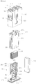
- FIG. 1 is a perspective view schematically illustrating an external shape of a strip cartridge for an integrated blood glucose meter according to an embodiment of the disclosure
- FIG. 2 is an exploded perspective view schematically illustrating a configuration of the strip cartridge for an integrated blood glucose meter according to the embodiment of the disclosure
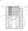
- FIG. 3 is a cross-sectional view schematically illustrating an internal structure of the strip cartridge for an integrated blood glucose meter according to the embodiment of the disclosure
- FIG. 4 is another cross-sectional view taken along line A-A in FIG. 3
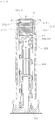
- FIG. 5 is another cross-sectional view schematically illustrating an internal structure of the strip cartridge for an integrated blood glucose meter according to the embodiment of the disclosure, taken in a further direction
- FIG. 6 is a view illustrating a structure of storing and stacking test strips in the strip cartridge for an integrated blood glucose meter according to the embodiment of the disclosure.
- the strip cartridge for an integrated blood glucose meter is configured to store a plurality of test strips 10 therein and to be accommodated in the integrated glucose meter.
- the strip cartridge includes a main container 100, an internal container 200, and a pressure loading module 300.
- the main container 100 provides an overall external structure of the strip cartridge.
- the main container 100 has the shape of a rectangular vessel with the bottom end portion thereof being open.
- the main container 100 has a strip supply port 110 on the top end portion thereof, the strip supply port 110 allowing the test strips to be discharged and supplied individually therethrough.
- a cartridge detector 130 storing unique identification information of a corresponding strip cartridge may be attached to an outer surface portion of the main container 100.
- the cartridge detector 130 may be implemented as an electronic chip, such that information regarding the strip cartridge, for example, information regarding the number of the test strips 10 stored in the strip cartridge is stored therein.
- the strip cartridge and the integrated glucose meter can transmit information to and receive information from each other via the cartridge detector 130.
- Various pieces of information regarding the strip cartridge can be transmitted to the integrated glucose meter, thereby facilitating the use and management of the strip cartridge.
- a fixing guide 120 for fixing the position of the main container 100 inserted into the integrated glucose meter may be provided on an outer surface portion of the main container 100. That is, the integrated glucose meter has an insertion port, through which the strip cartridge is inserted. When the insertion of the strip cartridge according to the embodiment of the disclosure into the insertion port of the integrated glucose meter is completed, the strip cartridge is required to fixedly remain at the inserted position without movement.
- the fixing guide 120 may be provided on the outer surface portion of the main container 100.
- the fixing guide 120 may have a variety of shapes.
- the fixing guide 120 may have the shape of a wedge inclined in the direction in which the main container 100 is inserted.
- the internal container 200 has the shape of a rectangular pipe such that the plurality of test strips 10 are stored and stacked in the internal space thereof, and is inserted into the main container 100.
- Catch holders 210 are provided on the top end portion of the internal container 200 to catch and hold an uppermost test strip 10 among the test strips 10 to prevent the test strips 10 from being dislodged upwardly.
- a guide rail (not shown) and a guide groove (not shown) having corresponding shapes may be provided on an outer surface portion of the internal container 200 and an inner surface portion of the main container 100 to guide a path on which the internal container 200 is inserted into the main container 100.
- each of the guide rail and the guide groove may be shaped to be asymmetrical in the lateral direction, such that the internal container 200 can only be inserted in a designated direction but cannot be inserted in the opposite direction.
- the pressure loading module 300 is coupled to a bottom end portion of the internal container 200, and is configured to elastically press the plurality of test strips 10, stored and stacked within the internal container 200, upward.
- the plurality of test strips 10 stacked and stored within the internal container 200 are elastically pressed upward within the internal container 200 by the pressure loading module 300, so that the uppermost test strip 10 among the test strips 10, stored and stacked within the internal container 200, is caught and held by the catch holders 210 provided on the top end portion of the internal container 200. Consequently, the plurality of test strips 10 are reliably held and maintained in the stacked and arranged state.
- the catch holders 210 are configured such that the uppermost test strip 10 caught and held by the catch holders 210 is loaded in the strip supply port 110 of the main container 100.
- the uppermost test strip 10 among the plurality of test strips 10 is loaded in the strip supply port 110 while being caught and held by the catch holders 210.
- a discharge/supply means 20 (see FIG. 4 ) separately provided inside of the integrated glucose meter moves linearly through the strip supply port 110
- the test strip 10 located in the upmost position of the internal container 200 is pressed by the discharge/supply means 20 to be moved and supplied to a separate strip outlet (not shown).
- a glucose measurement is performed by absorbing blood by the test strip 10.
- the pressure loading module 300 includes a base body 310, guide rods 320, a pressing body 330, and an elastic spring 340.
- the base body 310 is coupled to the main container 100 to close the open bottom end portion of the main container 100.
- the guide rods 320 are coupled to the base body 310 to protrude upwardly so as to be inserted into the internal container 200.
- the pressing body 330 is coupled to the guide rods 320 to be movable linearly in the top-bottom direction, thereby pressing and supporting the test strips 10.
- the elastic spring 340 applies upward elastic force to the pressing body 330 so that the test strips 10 in the internal space of the internal container 200 are elastically pressed upward.
- the pressing body 330 includes a pressing/supporting portion 332 having the shape of a flat plate to press and support the test strips 10 and guides 331 provided on opposite end portions of the pressing/supporting portion 332 to extend in the top-bottom direction.
- a plurality of projections 334 may be provided on the top surface of the pressing/supporting portion 332 and extend in a linear direction to reduce a surface area to be in contact with the corresponding test strip 10.
- the elastic spring 340 applies upward elastic force to the pressing body 330.
- the guides 331 respectively have a guide slit 333 extending in the top-bottom direction, the guide slit 333 being able to restrict a top-bottom movement path of the pressing body 330.
- the guide rods 320 may respectively have a stopper protrusion 322 able to be fitted into and engaged with the corresponding guide slit 333.
- the guide rod 320 of the pressing body 330 has a catch hook 321 protruding from an outer surface portion thereof.
- a catch hole 230 is provided in a side portion of the internal container 200, in a position corresponding to the catch hook 321.
- the pressure loading module 300 is fixedly coupled to the internal container 200.
- coupling protrusions 220 are provided on the bottom end portion of the internal container 200, and coupling holes 311 are provided on the top portion of the base body 310. The coupling protrusions 220 are fitted into and engaged with the coupling holes 311, thereby fixedly coupling the internal container 200 and the pressure loading module 300.
- catch protrusions 312 may protrude upwardly from the top surface of the base body 310, and the main container 100 may have coupling recesses 140 in inner surface portions thereof, such that the catch protrusions 312 may be fitted into and engaged with the coupling recesses 140. As the catch protrusions 312 are fitted into and engaged with the coupling recesses 140, the pressure loading module 300 is coupled to the main container 100.
- the strip supply port 110 of the main container 100 includes a protruding body 111 protruding upwardly from the top end portion of the main container 100, such that a single test strip 10 can be loaded in an internal space of a protruding area.
- Horizontal holes 112 and 113 are provided in opposite ends of the protruding body 111, such that the single test strip 10 can be slid and discharged by being pressed by the separate discharge/supply means 20.
- An intermediate opening 114 is formed in an intermediate portion of the protruding body 111, such that the catch holders 210 of the internal container 200 are disposed in the intermediate portion of the protruding body 111.
- the width d2 of the horizontal hole 113, through which the test strips 10 are discharged is set to be greater than the width d of the test strips 10, as illustrated in FIG. 4 .
- the width d1 of the remaining horizontal hole 112 is set to be smaller than the width d of the test strips 10.
- the discharge/supply means 20 has the shape of a flat plate to move through the horizontal holes 112 and 113 of the strip supply port 110. In this process, the discharge/supply means 20 pushes and supplies the uppermost test strip 10 outwardly.
- the width d3 of the discharge/supply means 20 shall be set to be smaller than or equal to the width d1 of the horizontal hole 112.
- test strips 10 can be discharged reversely from the internal space of the protruding body 111 through the inlet-side horizontal hole 112. Accordingly, the test strips 10 can be more accurately supplied.
- guide protrusions 115 may protrude inwardly from inner surface portions of the protruding body 111 to guide the test strips 10 to the designated position.
- the test strips 10 can be guided to the designated position by the guide protrusions 115 while being moved upwardly into the internal space of the protruding body 111. Accordingly, the operation of supplying the test strips 10 by the discharge/supply means 20 can be more accurately performed.
- the catch holders 210 provided on the top end portion of the internal container 200 include elastic bodies 211 protruding upwardly from opposite edges of the top end portion of the internal container 200 to face each other.
- the elastic bodies 211 are elastically deformable in a direction toward or away from each other.
- Catch protrusions 212 protrude from the top end portions of the elastic bodies 211, respectively, in a direction in which the catch protrusions 212 face each other.
- the test strips 10 are caught and held by the catch protrusions 212 when the test strips 10 located within the internal container 200 are pressed upwardly by the pressure loading module 300.
- the catch protrusions 212 are configured such that the bottom surfaces thereof are horizontal surfaces 212-1 to catch and hold the test strips 10 and the top surfaces thereof are inclined surfaces 212-2 inclined downwardly in the direction in which the catch protrusions 212 face each other.
- the test strips 10 may be input by being pressed downwardly in the direction from the top to the bottom of the catch holders 210.
- the test strips input to the internal space of the internal container 200 are pressed upwardly by the pressure loading module 300 and are caught and held by the catch protrusions 212 of the catch holders 210.
- the gripping means does not hold or remains attached to the test strips 10 after the test strips 10 have been input. Accordingly, it is possible to prevent a problem in that the test strips in a stacked and arranged state are misaligned or overturned, so that a fabrication process of the strip cartridge can be performed more rapidly and accurately.
- the inclined surfaces 212-2 provided on the top surfaces of the catch protrusions 212 of the catch holders 210 can facilitate the downward pressing and inputting of the test strips 10 to the internal container 200.
- the catch holders 210 having the elastic bodies 211 are elastically deformable in the direction toward or away from each other, the elastic bodies 211 can be elastically deformed in the direction toward or away from each other while the test strips 10 are being input to the internal container 200 by downward pressing, thereby facilitating the inputting of the test strips 10.
- the inner surfaces of the elastic bodies 211, facing each other, are provided as inclined surfaces 211-1 inclined toward each other in the direction from the bottom to the top, such that the test strips 10 are held and guided without movement in the internal space of the internal container 200.
- the test strips 10 stacked in the top-bottom direction in the internal space of the internal container 200 are loaded in the strip supply port 110 while being guided to a designated position. That is, in the integrated glucose meter, the discharge/supply means 20 discharges and supplies the test strips 10 individually to the outside, starting from the uppermost test strip 10, and the remaining test strips 10 stacked therebelow are moved upwardly by the elastic force of the pressure loading module 300. During the upward movement of the test strips 10 as described above, the test strips 10 are guided to a designated position by the inclined surfaces 211-1 of the elastic bodies 211. Accordingly, the test strips 10 can be supplied accurately.
- a dehumidifier 400 may be provided inside of the main container 100.
- the dehumidifier 400 can remove moisture in the internal space in order to prevent degradations in the test strips 10.
Landscapes
- Health & Medical Sciences (AREA)
- Life Sciences & Earth Sciences (AREA)
- Engineering & Computer Science (AREA)
- Biomedical Technology (AREA)
- Physics & Mathematics (AREA)
- Chemical & Material Sciences (AREA)
- Hematology (AREA)
- Pathology (AREA)
- General Health & Medical Sciences (AREA)
- Biophysics (AREA)
- Molecular Biology (AREA)
- Biochemistry (AREA)
- Analytical Chemistry (AREA)
- General Physics & Mathematics (AREA)
- Immunology (AREA)
- Medicinal Chemistry (AREA)
- Food Science & Technology (AREA)
- Urology & Nephrology (AREA)
- Animal Behavior & Ethology (AREA)
- Heart & Thoracic Surgery (AREA)
- Medical Informatics (AREA)
- Surgery (AREA)
- Public Health (AREA)
- Veterinary Medicine (AREA)
- Optics & Photonics (AREA)
- Ecology (AREA)
- Manufacturing & Machinery (AREA)
- Investigating Or Analysing Biological Materials (AREA)
- Measurement Of The Respiration, Hearing Ability, Form, And Blood Characteristics Of Living Organisms (AREA)
Abstract
Description
- The present disclosure relates to a strip cartridge for an integrated glucose meter. More particularly, the present disclosure relates to a strip cartridge for an integrated glucose meter, in which catch holders able to hold test strips is provided on the top end portion of an internal container, such that test strips can be accurately and easily stacked and stored in the internal space of the internal container, and the internal container having test strips stacked and stored therein can be inserted into a main container, so that a fabrication process can be conveniently and rapidly performed. In addition, errors, such as misalignment or overturning of the stacking and arrangement of test strips, which may occur during the storage of the test strips, can be prevented, thereby enabling the fabrication process to be performed more quickly and accurately.
- Diabetes or diabetes mellitus is a chronic medical condition that is common in modern people. In the Republic of Korea, it affects 2 million people, about 5% of the total population.
- Diabetes is caused from the absolute deficiency or relative insufficiency of insulin produced by the pancreas, due to various causes such as obesity, stress, poor eating habits, inherited hereditary factors, in which glucose balance in the blood may be disturbed, thereby resulting in a high blood sugar level.
- The blood usually contains a certain concentration of glucose, and tissue cells gain energy from the glucose.
- However, when the content of glucose is increased excessively, it is not properly stored in the liver, muscle, or adipose tissue and accumulates in the blood. As a result, patients with diabetes maintain a much higher blood glucose level than other people. Excessive blood glucose passes through the tissues and is discharged into the urine, resulting in deficiency of glucose, which is absolutely necessary for all tissues of the body, thereby causing abnormalities in respective body tissues.
- Diabetes mellitus is characterized by substantial absence of subjective symptoms at the beginning of the condition. When diabetes mellitus progresses, diabetes-specific symptoms such as diarrhea, polyuria, weight loss, general anxiety, skin itchiness, and scarring of the hands and feet are present. Further progression of diabetes leads to complications such as visual disturbances, hypertension, kidney disease, paralysis, periodontal disease, muscle spasms and neuralgia, as well as gangrene.
- Systematic blood glucose measurement and treatment should be performed to diagnose diabetes beforehand and manage the condition to prevent the progression of diabetes into complications associated therewith.
- For people with diabetes or people having higher than normal blood glucose, even though diabetes has not yet developed, medical device manufacturers offer a variety of blood glucose meters to measure blood glucose at home.
- In such a blood glucose meter, a test strip is input to a container of the blood glucose meter, a blood sample is absorbed by the input test strip, a glucose level is measured by inspecting the absorbed blood sample using a glucose measuring module within the container, and a measurement result is calculated by a calculator and is output on a separate display.
- To use such a blood glucose meter, a user should possess and carry a separate strip storage container in which a plurality of test strips are stored. A glucose measuring process is performed by taking one test strip from the strip storage container and inputting the test strip to the blood glucose meter, and after the glucose measuring process, the used test strip must be discharged and discarded, thereby making it inconvenient to use the blood glucose meter. In addition, since the strip storage container must be carried separately, there are significant difficulties in the use of the blood glucose meter.
- To reduce or overcome such inconveniences in the use thereof, various types of integrated blood glucose meters have recently been developed, in each of which a strip cartridge storing a plurality of test strips can be accommodated in an internal space of the blood glucose meter, and the test strips can be supplied individually from the strip cartridge.
- For such an integrated glucose meter, a strip cartridge is essential. The strip cartridge is fabricated such that a plurality of test strips are stored in the strip cartridge. A process of storing a plurality of test strips in a strip cartridge is generally performed as an automated process. In the process of stacking and storing the plurality of test strips, problems may frequently occur. For example, the test strips in a stacked and arranged state may be misaligned or overturned. Accordingly, a range of difficulties may be caused in fabrication. For example, a defect rate may be increased, and a fabrication process may be stopped.
- Accordingly, the present disclosure has been made in consideration of the above-described problems occurring in the related art, and an objective of the present disclosure is to provide a strip cartridge for an integrated glucose meter, in which errors, such as misalignment or overturning of the stacking and arrangement of test strips, which may occur during the storage of test strips in the cartridge, can be prevented, thereby enabling a fabrication process to be performed more quickly and accurately.
- Another objective of the present disclosure is to provide a strip cartridge for an integrated glucose meter, in which catch holders able to hold test strips are provided on the top end portion of an internal container, such that test strips can be accurately and easily stacked and stored in the internal space of the internal container, and the internal container having test strips stacked and stored therein can be inserted into a main container, so that the fabrication process can be conveniently and rapidly performed.
- Another objective of the present disclosure is to provide a strip cartridge for an integrated glucose meter, in which, in a process of loading a test strip stacked and stored within the cartridge to an uppermost layer, the test strip can be guided to a designated position, so that the supply of the test strip to be used in the integrated glucose meter can be accurately performed.
- According to an aspect of the present disclosure, provided is a strip cartridge for an integrated blood glucose meter. The strip cartridge is insertable into the integrated glucose meter and is configured such that a plurality of test strips are stored therein. The strip cartridge may include: a vessel-shaped main container having an open bottom end portion and a strip supply port provided on a top end portion, the strip supply port allowing test strips to be discharged individually therethrough; an internal container shaped as a rectangular pipe allowing test strips to be stored and stacked on each other in a top-bottom direction in an internal space of the internal container, wherein the internal container is inserted into the main container and includes catch holders on a top end portion thereof to prevent test strips from being dislodged upwardly; a pressure loading module coupled to a bottom end portion of the internal container and elastically pressing test strips, stacked in the internal space of the internal container, in a direction from bottom to top.
- Here, the catch holders may be configured such that an uppermost test strip caught and held by the catch holders is loaded in the strip supply port.
- In addition, the catch holders may include: elastic bodies protruding upwardly from opposite edges of the top end portion of the internal container to face each other, and being elastically deformable in a direction toward or away from each other; and catch protrusions protrude from top end portions of the elastic bodies, respectively, in a direction in which the catch protrusions face each other. Test strips may be caught and held by the catch protrusions when test strips located within the internal container are pressed upwardly by the pressure loading module.
- In addition, the catch protrusions may have horizontal bottom surfaces, by which test strips are caught and held, and inclined top surfaces inclined downwardly in a direction in which the catch protrusions face each other.
- In addition, the elastic bodies may have inclined surfaces facing each other, the inclined surfaces being inclined toward each other in a direction from bottom to top, such that test strips are held and guided without movement.
- In addition, the strip supply port may include: a protruding body protruding upwardly from the top end portion of the main container, enabling a single test strip to be loaded in an internal space of a protruding area; and horizontal holes provided in opposite ends of the protruding body, enabling the single test strip to be slid and discharged by being pressed by the separate discharge/supply means. An intermediate opening may be provided in an intermediate portion of the protruding body, such that the catch holders of the internal container are disposed in the intermediate portion of the protruding body.
- In addition, among the horizontal holes provided in the opposite ends of the protruding body, a width of the horizontal hole, through which test strips are discharged, may be greater than a width of test strips, and a width of the remaining horizontal hole may be smaller than the width of test strips.
- In addition, the pressure loading module may include: a base body coupled to the main container to close the open bottom end portion of the main container; a guide rod coupled to the base body to protrude upwardly so as to be inserted into the internal container; a pressing body coupled to the guide rod to be movable linearly in a top-bottom direction; and an elastic spring applying upward elastic force to the pressing body so that test strips in the internal space of the internal container are elastically pressed upward.
- In addition, a fixing guide for fixing the position of the main container inserted into the integrated glucose meter may be provided on an outer surface portion of the main container.
- According to the disclosure, errors, such as misalignment or overturning of the stacking and arrangement of test strips, which may occur during the storage of test strips in the cartridge, can be prevented, thereby enabling a fabrication process to be performed more quickly and accurately.
- In addition, the catch holders able to hold test strips are provided on the top end portion of the internal container, such that test strips can be accurately and easily stacked and stored in the internal space of the internal container, and the internal container having test strips stacked and stored therein can be inserted into the main container, so that the fabrication process can be conveniently and rapidly performed.
- In addition, in a process of loading a test strip stacked and stored within the cartridge to an uppermost layer, the test strip can be guided to a designated position, so that the supply of the test strip to be used in the integrated glucose meter can be accurately performed.
-
-
FIG. 1 is a perspective view schematically illustrating an external shape of a strip cartridge for an integrated blood glucose meter according to an embodiment of the disclosure; -
FIG. 2 is an exploded perspective view schematically illustrating a configuration of the strip cartridge for an integrated blood glucose meter according to the embodiment of the disclosure; -
FIG. 3 is a cross-sectional view schematically illustrating an internal structure of the strip cartridge for an integrated blood glucose meter according to the embodiment of the disclosure; -
FIG. 4 is another cross-sectional view taken along line A-A inFIG. 3 ; -
FIG. 5 is another cross-sectional view schematically illustrating an internal structure of the strip cartridge for an integrated blood glucose meter according to the embodiment of the disclosure, taken in a further direction; and -
FIG. 6 is a view illustrating a structure of storing and stacking test strips in the strip cartridge for an integrated blood glucose meter according to the embodiment of the disclosure. - Hereinafter, embodiments of the present disclosure will be described in detail with reference to the accompanying drawings. Throughout this document, reference should be made to the drawings, in which the same reference numerals and symbols will be used to designate the same or like components. In the following description of the present disclosure, detailed descriptions of known functions and components incorporated herein will be omitted in the case that the subject matter of the present disclosure may be rendered unclear thereby.
-
FIG. 1 is a perspective view schematically illustrating an external shape of a strip cartridge for an integrated blood glucose meter according to an embodiment of the disclosure,FIG. 2 is an exploded perspective view schematically illustrating a configuration of the strip cartridge for an integrated blood glucose meter according to the embodiment of the disclosure,FIG. 3 is a cross-sectional view schematically illustrating an internal structure of the strip cartridge for an integrated blood glucose meter according to the embodiment of the disclosure,FIG. 4 is another cross-sectional view taken along line A-A inFIG. 3 ,FIG. 5 is another cross-sectional view schematically illustrating an internal structure of the strip cartridge for an integrated blood glucose meter according to the embodiment of the disclosure, taken in a further direction, andFIG. 6 is a view illustrating a structure of storing and stacking test strips in the strip cartridge for an integrated blood glucose meter according to the embodiment of the disclosure. - The strip cartridge for an integrated blood glucose meter according to the embodiment of the disclosure is configured to store a plurality of
test strips 10 therein and to be accommodated in the integrated glucose meter. The strip cartridge includes amain container 100, aninternal container 200, and apressure loading module 300. - The
main container 100 provides an overall external structure of the strip cartridge. Themain container 100 has the shape of a rectangular vessel with the bottom end portion thereof being open. Themain container 100 has astrip supply port 110 on the top end portion thereof, thestrip supply port 110 allowing the test strips to be discharged and supplied individually therethrough. - A
cartridge detector 130 storing unique identification information of a corresponding strip cartridge may be attached to an outer surface portion of themain container 100. Thecartridge detector 130 may be implemented as an electronic chip, such that information regarding the strip cartridge, for example, information regarding the number of thetest strips 10 stored in the strip cartridge is stored therein. Thus, when the strip cartridge is inserted into the integrated glucose meter, the strip cartridge and the integrated glucose meter can transmit information to and receive information from each other via thecartridge detector 130. Various pieces of information regarding the strip cartridge can be transmitted to the integrated glucose meter, thereby facilitating the use and management of the strip cartridge. - In addition, a fixing
guide 120 for fixing the position of themain container 100 inserted into the integrated glucose meter may be provided on an outer surface portion of themain container 100. That is, the integrated glucose meter has an insertion port, through which the strip cartridge is inserted. When the insertion of the strip cartridge according to the embodiment of the disclosure into the insertion port of the integrated glucose meter is completed, the strip cartridge is required to fixedly remain at the inserted position without movement. In this regard, the fixingguide 120 may be provided on the outer surface portion of themain container 100. The fixingguide 120 may have a variety of shapes. For example, the fixingguide 120 may have the shape of a wedge inclined in the direction in which themain container 100 is inserted. - The
internal container 200 has the shape of a rectangular pipe such that the plurality oftest strips 10 are stored and stacked in the internal space thereof, and is inserted into themain container 100.Catch holders 210 are provided on the top end portion of theinternal container 200 to catch and hold anuppermost test strip 10 among thetest strips 10 to prevent thetest strips 10 from being dislodged upwardly. A guide rail (not shown) and a guide groove (not shown) having corresponding shapes may be provided on an outer surface portion of theinternal container 200 and an inner surface portion of themain container 100 to guide a path on which theinternal container 200 is inserted into themain container 100. Here, each of the guide rail and the guide groove may be shaped to be asymmetrical in the lateral direction, such that theinternal container 200 can only be inserted in a designated direction but cannot be inserted in the opposite direction. - The
pressure loading module 300 is coupled to a bottom end portion of theinternal container 200, and is configured to elastically press the plurality oftest strips 10, stored and stacked within theinternal container 200, upward. - According to this structure, the plurality of
test strips 10 stacked and stored within theinternal container 200 are elastically pressed upward within theinternal container 200 by thepressure loading module 300, so that theuppermost test strip 10 among thetest strips 10, stored and stacked within theinternal container 200, is caught and held by thecatch holders 210 provided on the top end portion of theinternal container 200. Consequently, the plurality oftest strips 10 are reliably held and maintained in the stacked and arranged state. - Here, the
catch holders 210 are configured such that theuppermost test strip 10 caught and held by thecatch holders 210 is loaded in thestrip supply port 110 of themain container 100. Thus, theuppermost test strip 10 among the plurality oftest strips 10 is loaded in thestrip supply port 110 while being caught and held by thecatch holders 210. In this state, when a discharge/supply means 20 (seeFIG. 4 ) separately provided inside of the integrated glucose meter moves linearly through thestrip supply port 110, thetest strip 10 located in the upmost position of theinternal container 200 is pressed by the discharge/supply means 20 to be moved and supplied to a separate strip outlet (not shown). In this state in which thetest strip 10 is supplied and discharged through the strip outlet, a glucose measurement is performed by absorbing blood by thetest strip 10. - Next, a detailed configuration of the strip cartridge according to the embodiment of the disclosure will be described in more detail.
- First, the
pressure loading module 300 includes abase body 310, guiderods 320, apressing body 330, and anelastic spring 340. Thebase body 310 is coupled to themain container 100 to close the open bottom end portion of themain container 100. Theguide rods 320 are coupled to thebase body 310 to protrude upwardly so as to be inserted into theinternal container 200. Thepressing body 330 is coupled to theguide rods 320 to be movable linearly in the top-bottom direction, thereby pressing and supporting the test strips 10. Theelastic spring 340 applies upward elastic force to thepressing body 330 so that thetest strips 10 in the internal space of theinternal container 200 are elastically pressed upward. - The
pressing body 330 includes a pressing/supportingportion 332 having the shape of a flat plate to press and support thetest strips 10 and guides 331 provided on opposite end portions of the pressing/supportingportion 332 to extend in the top-bottom direction. A plurality ofprojections 334 may be provided on the top surface of the pressing/supportingportion 332 and extend in a linear direction to reduce a surface area to be in contact with thecorresponding test strip 10. Theelastic spring 340 applies upward elastic force to thepressing body 330. Here, theguides 331 respectively have aguide slit 333 extending in the top-bottom direction, the guide slit 333 being able to restrict a top-bottom movement path of thepressing body 330. Theguide rods 320 may respectively have astopper protrusion 322 able to be fitted into and engaged with the corresponding guide slit 333. - In addition, the
guide rod 320 of thepressing body 330 has acatch hook 321 protruding from an outer surface portion thereof. Acatch hole 230 is provided in a side portion of theinternal container 200, in a position corresponding to thecatch hook 321. As thecatch hook 321 is fitted into and engaged with thecatch hole 230, thepressure loading module 300 is fixedly coupled to theinternal container 200. In addition, couplingprotrusions 220 are provided on the bottom end portion of theinternal container 200, andcoupling holes 311 are provided on the top portion of thebase body 310. The coupling protrusions 220 are fitted into and engaged with the coupling holes 311, thereby fixedly coupling theinternal container 200 and thepressure loading module 300. - In addition,
separate catch protrusions 312 may protrude upwardly from the top surface of thebase body 310, and themain container 100 may havecoupling recesses 140 in inner surface portions thereof, such that thecatch protrusions 312 may be fitted into and engaged with the coupling recesses 140. As thecatch protrusions 312 are fitted into and engaged with the coupling recesses 140, thepressure loading module 300 is coupled to themain container 100. - The
strip supply port 110 of themain container 100 includes aprotruding body 111 protruding upwardly from the top end portion of themain container 100, such that asingle test strip 10 can be loaded in an internal space of a protruding area.Horizontal holes body 111, such that thesingle test strip 10 can be slid and discharged by being pressed by the separate discharge/supply means 20. Anintermediate opening 114 is formed in an intermediate portion of the protrudingbody 111, such that thecatch holders 210 of theinternal container 200 are disposed in the intermediate portion of the protrudingbody 111. - Here, among the
horizontal holes body 111, the width d2 of thehorizontal hole 113, through which thetest strips 10 are discharged, is set to be greater than the width d of thetest strips 10, as illustrated inFIG. 4 . The width d1 of the remaininghorizontal hole 112 is set to be smaller than the width d of the test strips 10. The discharge/supply means 20 has the shape of a flat plate to move through thehorizontal holes strip supply port 110. In this process, the discharge/supply means 20 pushes and supplies theuppermost test strip 10 outwardly. Here, the width d3 of the discharge/supply means 20 shall be set to be smaller than or equal to the width d1 of thehorizontal hole 112. - This structure can prevent any possibility that the
test strips 10 may be discharged reversely from the internal space of the protrudingbody 111 through the inlet-sidehorizontal hole 112. Accordingly, thetest strips 10 can be more accurately supplied. - In addition, guide
protrusions 115 may protrude inwardly from inner surface portions of the protrudingbody 111 to guide thetest strips 10 to the designated position. Thus, even in the case in which the arranged state of thetest strips 10, stacked within theinternal container 200 in the top direction, is slightly misaligned, thetest strips 10 can be guided to the designated position by theguide protrusions 115 while being moved upwardly into the internal space of the protrudingbody 111. Accordingly, the operation of supplying thetest strips 10 by the discharge/supply means 20 can be more accurately performed. - In addition, the
catch holders 210 provided on the top end portion of theinternal container 200 includeelastic bodies 211 protruding upwardly from opposite edges of the top end portion of theinternal container 200 to face each other. Theelastic bodies 211 are elastically deformable in a direction toward or away from each other. Catchprotrusions 212 protrude from the top end portions of theelastic bodies 211, respectively, in a direction in which thecatch protrusions 212 face each other. The test strips 10 are caught and held by thecatch protrusions 212 when thetest strips 10 located within theinternal container 200 are pressed upwardly by thepressure loading module 300. - Here, the
catch protrusions 212 are configured such that the bottom surfaces thereof are horizontal surfaces 212-1 to catch and hold thetest strips 10 and the top surfaces thereof are inclined surfaces 212-2 inclined downwardly in the direction in which thecatch protrusions 212 face each other. - According to this structure, as illustrated in
FIG. 6 , in the process of inputting thetest strips 10 to the internal space of theinternal container 200, thetest strips 10 may be input by being pressed downwardly in the direction from the top to the bottom of thecatch holders 210. In this case, the test strips input to the internal space of theinternal container 200 are pressed upwardly by thepressure loading module 300 and are caught and held by thecatch protrusions 212 of thecatch holders 210. Thus, in the process of inputting thetest strips 10 to the internal space of theinternal container 200 using a separate gripping means (not shown), the gripping means does not hold or remains attached to thetest strips 10 after thetest strips 10 have been input. Accordingly, it is possible to prevent a problem in that the test strips in a stacked and arranged state are misaligned or overturned, so that a fabrication process of the strip cartridge can be performed more rapidly and accurately. - In addition, in the process of inputting the
test strips 10 to theinternal container 200 by pressing thetest strips 10 downwardly in the direction of the top to the bottom of thecatch holders 210, the inclined surfaces 212-2 provided on the top surfaces of thecatch protrusions 212 of thecatch holders 210 can facilitate the downward pressing and inputting of thetest strips 10 to theinternal container 200. Furthermore, since thecatch holders 210 having theelastic bodies 211 are elastically deformable in the direction toward or away from each other, theelastic bodies 211 can be elastically deformed in the direction toward or away from each other while thetest strips 10 are being input to theinternal container 200 by downward pressing, thereby facilitating the inputting of the test strips 10. - In addition, the inner surfaces of the
elastic bodies 211, facing each other, are provided as inclined surfaces 211-1 inclined toward each other in the direction from the bottom to the top, such that thetest strips 10 are held and guided without movement in the internal space of theinternal container 200. - According to the above-described structure, the
test strips 10 stacked in the top-bottom direction in the internal space of theinternal container 200 are loaded in thestrip supply port 110 while being guided to a designated position. That is, in the integrated glucose meter, the discharge/supply means 20 discharges and supplies thetest strips 10 individually to the outside, starting from theuppermost test strip 10, and the remainingtest strips 10 stacked therebelow are moved upwardly by the elastic force of thepressure loading module 300. During the upward movement of thetest strips 10 as described above, thetest strips 10 are guided to a designated position by the inclined surfaces 211-1 of theelastic bodies 211. Accordingly, thetest strips 10 can be supplied accurately. - In addition, a
dehumidifier 400 may be provided inside of themain container 100. Thedehumidifier 400 can remove moisture in the internal space in order to prevent degradations in the test strips 10. - The foregoing descriptions have been presented in order to explain certain principles of the present disclosure by way of example. A person skilled in the art to which the present disclosure relates could make various modifications and variations without departing from the essential features of the present disclosure. The foregoing embodiments disclosed herein shall be interpreted as being illustrative, while not being limitative, of the principle and scope of the present disclosure. It should be understood that the scope of the present disclosure shall be defined by the appended Claims and all of their equivalents fall within the scope of the present disclosure.
Claims (9)
- A strip cartridge for an integrated blood glucose meter, in which the strip cartridge is insertable into the integrated glucose meter and is configured such that a plurality of test strips are stored therein, the strip cartridge comprising:a vessel-shaped main container having an open bottom end portion and a strip supply port provided on a top end portion, the strip supply port allowing test strips to be discharged individually therethrough;an internal container shaped as a rectangular pipe allowing test strips to be stored and stacked on each other in a top-bottom direction in an internal space of the internal container, wherein the internal container is inserted into the main container and includes catch holders on a top end portion thereof to prevent test strips from being dislodged upwardly;a pressure loading module coupled to a bottom end portion of the internal container and elastically pressing test strips, stacked in the internal space of the internal container, in a direction from bottom to top.
- The strip cartridge according to claim 1, wherein the catch holders are configured such that an uppermost test strip caught and held by the catch holders is loaded in the strip supply port.
- The strip cartridge according to claim 2, wherein the catch holders include:elastic bodies protruding upwardly from opposite edges of the top end portion of the internal container to face each other, and being elastically deformable in a direction toward or away from each other; andcatch protrusions protrude from top end portions of the elastic bodies, respectively, in a direction in which the catch protrusions face each other,wherein test strips are caught and held by the catch protrusions when test strips located within the internal container are pressed upwardly by the pressure loading module.
- The strip cartridge according to claim 3, wherein the catch protrusions have horizontal bottom surfaces, by which test strips are caught and held, and inclined top surfaces inclined downwardly in a direction in which the catch protrusions face each other.
- The strip cartridge according to claim 4, wherein the elastic bodies have inclined surfaces facing each other, the inclined surfaces being inclined toward each other in a direction from bottom to top, such that test strips are held and guided without movement.
- The strip cartridge according to claim 2, wherein the strip supply port includes:a protruding body protruding upwardly from the top end portion of the main container, enabling a single test strip to be loaded in an internal space of a protruding area; andhorizontal holes provided in opposite ends of the protruding body, enabling the single test strip to be slid and discharged by being pressed by the separate discharge/supply means,wherein an intermediate opening is provided in an intermediate portion of the protruding body, such that the catch holders of the internal container are disposed in the intermediate portion of the protruding body.
- The strip cartridge according to claim 6, wherein, among the horizontal holes provided in the opposite ends of the protruding body, a width of the horizontal hole, through which test strips are discharged, is greater than a width of test strips, and a width of the remaining horizontal hole is smaller than the width of test strips.
- The strip cartridge according to one of claims 1 to 7, wherein the pressure loading module includes:a base body coupled to the main container to close the open bottom end portion of the main container;a guide rod coupled to the base body to protrude upwardly so as to be inserted into the internal container;a pressing body coupled to the guide rod to be movable linearly in a top-bottom direction; andan elastic spring applying upward elastic force to the pressing body so that test strips in the internal space of the internal container are elastically pressed upward.
- The strip cartridge according to one of claims 1 to 7, wherein a fixing guide for fixing the position of the main container inserted into the integrated glucose meter is provided on an outer surface portion of the main container.
Applications Claiming Priority (2)
| Application Number | Priority Date | Filing Date | Title |
|---|---|---|---|
| KR1020170068965A KR101993681B1 (en) | 2017-06-02 | 2017-06-02 | Strip cartridge for integrated measuring meter of blood glucose |
| PCT/KR2018/004831 WO2018221862A1 (en) | 2017-06-02 | 2018-04-26 | Integrated strip cartridge for glucose meter |
Publications (3)
| Publication Number | Publication Date |
|---|---|
| EP3632312A1 true EP3632312A1 (en) | 2020-04-08 |
| EP3632312A4 EP3632312A4 (en) | 2021-04-07 |
| EP3632312B1 EP3632312B1 (en) | 2023-05-24 |
Family
ID=64455096
Family Applications (1)
| Application Number | Title | Priority Date | Filing Date |
|---|---|---|---|
| EP18808879.3A Active EP3632312B1 (en) | 2017-06-02 | 2018-04-26 | Integrated strip cartridge for glucose meter |
Country Status (3)
| Country | Link |
|---|---|
| EP (1) | EP3632312B1 (en) |
| KR (1) | KR101993681B1 (en) |
| WO (1) | WO2018221862A1 (en) |
Family Cites Families (10)
| Publication number | Priority date | Publication date | Assignee | Title |
|---|---|---|---|---|
| GB0017737D0 (en) * | 2000-07-20 | 2000-09-06 | Hypoguard Limited | Test device |
| KR100893275B1 (en) * | 2001-03-29 | 2009-04-17 | 라이프스캔 스코트랜드 리미티드 | Integrated sample test instrument |
| US6908008B2 (en) * | 2001-12-21 | 2005-06-21 | Lifescan, Inc. | Test device with means for storing and dispensing diagnostic strips |
| CA2584766A1 (en) * | 2004-10-20 | 2006-04-27 | Jeffery S. Reynolds | Cartridge for containing and dispensing test sensors |
| US7922971B2 (en) * | 2005-11-30 | 2011-04-12 | Abbott Diabetes Care Inc. | Integrated meter for analyzing biological samples |
| US7935307B2 (en) * | 2007-05-31 | 2011-05-03 | EOS Health, DVC. | Disposable, refillable glucometer with cell phone interface for transmission of results |
| KR101348410B1 (en) * | 2010-02-16 | 2014-01-07 | 최인상 | Apparatus for storing strip using glucose meter and strip storing apparatus |
| US8333716B1 (en) * | 2011-06-21 | 2012-12-18 | Yofimeter, Llc | Methods for using an analyte testing device |
| US9383333B2 (en) * | 2012-05-31 | 2016-07-05 | Ascensia Diabetes Care Holdings Ag | Replaceable multistrip cartridge and biosensor meter |
| KR20140094931A (en) | 2013-01-23 | 2014-07-31 | 삼성전자주식회사 | Blood glucose test meter |
-
2017
- 2017-06-02 KR KR1020170068965A patent/KR101993681B1/en not_active Expired - Fee Related
-
2018
- 2018-04-26 EP EP18808879.3A patent/EP3632312B1/en active Active
- 2018-04-26 WO PCT/KR2018/004831 patent/WO2018221862A1/en not_active Ceased
Also Published As
| Publication number | Publication date |
|---|---|
| KR101993681B1 (en) | 2019-06-28 |
| WO2018221862A1 (en) | 2018-12-06 |
| KR20180133011A (en) | 2018-12-13 |
| EP3632312A4 (en) | 2021-04-07 |
| EP3632312B1 (en) | 2023-05-24 |
Similar Documents
| Publication | Publication Date | Title |
|---|---|---|
| US12251217B2 (en) | Applicator for continuous blood glucose measurement | |
| EP3412205B1 (en) | Strip ejection apparatus for blood glucose meter | |
| KR102200142B1 (en) | Sensor unit for continuous glucose monitoring system | |
| US20260020785A1 (en) | Body attachable unit for continuous blood glucose measurement | |
| US20240358285A1 (en) | Body attachable unit for continuous blood glucose measurement | |
| EP3632312B1 (en) | Integrated strip cartridge for glucose meter | |
| EP3663759A1 (en) | Sensor clip assembly for stacked sensor dispensing system | |
| TW201307841A (en) | A cartridge for test strips and a method for including a calibration code onto the cartridge and for reading the code | |
| US20240293052A1 (en) | Sensor unit for continuous blood glucose measurement | |
| US12285254B2 (en) | Body attachable unit for continuous blood glucose measurement | |
| EP3616616B1 (en) | Integral blood glucose meter displaying information on number of remaining test strips | |
| EP3533395B1 (en) | Integrated blood glucose measuring device | |
| EP3616615B1 (en) | Integral blood glucose meter having ejecting unit | |
| EP3879256A1 (en) | Cholesterol measurement device | |
| CN223619111U (en) | A foil-packaged tablet dispenser | |
| CN223836239U (en) | Portable blood glucose test paper box | |
| CN221733407U (en) | A one-stop slide tray | |
| EP3616614B1 (en) | Integral blood glucose meter | |
| NZ775061B2 (en) | Sensor unit for continuous blood glucose measurement |
Legal Events
| Date | Code | Title | Description |
|---|---|---|---|
| STAA | Information on the status of an ep patent application or granted ep patent |
Free format text: STATUS: THE INTERNATIONAL PUBLICATION HAS BEEN MADE |
|
| PUAI | Public reference made under article 153(3) epc to a published international application that has entered the european phase |
Free format text: ORIGINAL CODE: 0009012 |
|
| STAA | Information on the status of an ep patent application or granted ep patent |
Free format text: STATUS: REQUEST FOR EXAMINATION WAS MADE |
|
| 17P | Request for examination filed |
Effective date: 20191227 |
|
| AK | Designated contracting states |
Kind code of ref document: A1 Designated state(s): AL AT BE BG CH CY CZ DE DK EE ES FI FR GB GR HR HU IE IS IT LI LT LU LV MC MK MT NL NO PL PT RO RS SE SI SK SM TR |
|
| AX | Request for extension of the european patent |
Extension state: BA ME |
|
| DAV | Request for validation of the european patent (deleted) | ||
| DAX | Request for extension of the european patent (deleted) | ||
| A4 | Supplementary search report drawn up and despatched |
Effective date: 20210310 |
|
| RIC1 | Information provided on ipc code assigned before grant |
Ipc: G01N 33/487 20060101ALI20210303BHEP Ipc: G01N 33/49 20060101ALI20210303BHEP Ipc: G01N 35/00 20060101ALI20210303BHEP Ipc: A61B 5/155 20060101ALI20210303BHEP Ipc: A61B 5/15 20060101AFI20210303BHEP |
|
| GRAP | Despatch of communication of intention to grant a patent |
Free format text: ORIGINAL CODE: EPIDOSNIGR1 |
|
| STAA | Information on the status of an ep patent application or granted ep patent |
Free format text: STATUS: GRANT OF PATENT IS INTENDED |
|
| INTG | Intention to grant announced |
Effective date: 20221213 |
|
| RIN1 | Information on inventor provided before grant (corrected) |
Inventor name: NAM, HAK HYUN Inventor name: CHA, GEUN SIG Inventor name: LEE, JIN WON Inventor name: WANG, JI HOON Inventor name: RYU, GOANG YEL Inventor name: CHOI, HYUN HO Inventor name: CHAE, KYUNG CHUL |
|
| GRAS | Grant fee paid |
Free format text: ORIGINAL CODE: EPIDOSNIGR3 |
|
| GRAA | (expected) grant |
Free format text: ORIGINAL CODE: 0009210 |
|
| STAA | Information on the status of an ep patent application or granted ep patent |
Free format text: STATUS: THE PATENT HAS BEEN GRANTED |
|
| AK | Designated contracting states |
Kind code of ref document: B1 Designated state(s): AL AT BE BG CH CY CZ DE DK EE ES FI FR GB GR HR HU IE IS IT LI LT LU LV MC MK MT NL NO PL PT RO RS SE SI SK SM TR |
|
| REG | Reference to a national code |
Ref country code: GB Ref legal event code: FG4D |
|
| REG | Reference to a national code |
Ref country code: CH Ref legal event code: EP |
|
| REG | Reference to a national code |
Ref country code: DE Ref legal event code: R096 Ref document number: 602018050247 Country of ref document: DE |
|
| REG | Reference to a national code |
Ref country code: AT Ref legal event code: REF Ref document number: 1569054 Country of ref document: AT Kind code of ref document: T Effective date: 20230615 |
|
| REG | Reference to a national code |
Ref country code: IE Ref legal event code: FG4D |
|
| REG | Reference to a national code |
Ref country code: LT Ref legal event code: MG9D |
|
| REG | Reference to a national code |
Ref country code: NL Ref legal event code: MP Effective date: 20230524 |
|
| REG | Reference to a national code |
Ref country code: AT Ref legal event code: MK05 Ref document number: 1569054 Country of ref document: AT Kind code of ref document: T Effective date: 20230524 |
|
| PG25 | Lapsed in a contracting state [announced via postgrant information from national office to epo] |
Ref country code: SE Free format text: LAPSE BECAUSE OF FAILURE TO SUBMIT A TRANSLATION OF THE DESCRIPTION OR TO PAY THE FEE WITHIN THE PRESCRIBED TIME-LIMIT Effective date: 20230524 Ref country code: PT Free format text: LAPSE BECAUSE OF FAILURE TO SUBMIT A TRANSLATION OF THE DESCRIPTION OR TO PAY THE FEE WITHIN THE PRESCRIBED TIME-LIMIT Effective date: 20230925 Ref country code: NO Free format text: LAPSE BECAUSE OF FAILURE TO SUBMIT A TRANSLATION OF THE DESCRIPTION OR TO PAY THE FEE WITHIN THE PRESCRIBED TIME-LIMIT Effective date: 20230824 Ref country code: NL Free format text: LAPSE BECAUSE OF FAILURE TO SUBMIT A TRANSLATION OF THE DESCRIPTION OR TO PAY THE FEE WITHIN THE PRESCRIBED TIME-LIMIT Effective date: 20230524 Ref country code: ES Free format text: LAPSE BECAUSE OF FAILURE TO SUBMIT A TRANSLATION OF THE DESCRIPTION OR TO PAY THE FEE WITHIN THE PRESCRIBED TIME-LIMIT Effective date: 20230524 Ref country code: AT Free format text: LAPSE BECAUSE OF FAILURE TO SUBMIT A TRANSLATION OF THE DESCRIPTION OR TO PAY THE FEE WITHIN THE PRESCRIBED TIME-LIMIT Effective date: 20230524 |
|
| PG25 | Lapsed in a contracting state [announced via postgrant information from national office to epo] |
Ref country code: RS Free format text: LAPSE BECAUSE OF FAILURE TO SUBMIT A TRANSLATION OF THE DESCRIPTION OR TO PAY THE FEE WITHIN THE PRESCRIBED TIME-LIMIT Effective date: 20230524 Ref country code: PL Free format text: LAPSE BECAUSE OF FAILURE TO SUBMIT A TRANSLATION OF THE DESCRIPTION OR TO PAY THE FEE WITHIN THE PRESCRIBED TIME-LIMIT Effective date: 20230524 Ref country code: LV Free format text: LAPSE BECAUSE OF FAILURE TO SUBMIT A TRANSLATION OF THE DESCRIPTION OR TO PAY THE FEE WITHIN THE PRESCRIBED TIME-LIMIT Effective date: 20230524 Ref country code: LT Free format text: LAPSE BECAUSE OF FAILURE TO SUBMIT A TRANSLATION OF THE DESCRIPTION OR TO PAY THE FEE WITHIN THE PRESCRIBED TIME-LIMIT Effective date: 20230524 Ref country code: IS Free format text: LAPSE BECAUSE OF FAILURE TO SUBMIT A TRANSLATION OF THE DESCRIPTION OR TO PAY THE FEE WITHIN THE PRESCRIBED TIME-LIMIT Effective date: 20230924 Ref country code: HR Free format text: LAPSE BECAUSE OF FAILURE TO SUBMIT A TRANSLATION OF THE DESCRIPTION OR TO PAY THE FEE WITHIN THE PRESCRIBED TIME-LIMIT Effective date: 20230524 Ref country code: GR Free format text: LAPSE BECAUSE OF FAILURE TO SUBMIT A TRANSLATION OF THE DESCRIPTION OR TO PAY THE FEE WITHIN THE PRESCRIBED TIME-LIMIT Effective date: 20230825 |
|
| PG25 | Lapsed in a contracting state [announced via postgrant information from national office to epo] |
Ref country code: FI Free format text: LAPSE BECAUSE OF FAILURE TO SUBMIT A TRANSLATION OF THE DESCRIPTION OR TO PAY THE FEE WITHIN THE PRESCRIBED TIME-LIMIT Effective date: 20230524 |
|
| PG25 | Lapsed in a contracting state [announced via postgrant information from national office to epo] |
Ref country code: SK Free format text: LAPSE BECAUSE OF FAILURE TO SUBMIT A TRANSLATION OF THE DESCRIPTION OR TO PAY THE FEE WITHIN THE PRESCRIBED TIME-LIMIT Effective date: 20230524 |
|
| PG25 | Lapsed in a contracting state [announced via postgrant information from national office to epo] |
Ref country code: SM Free format text: LAPSE BECAUSE OF FAILURE TO SUBMIT A TRANSLATION OF THE DESCRIPTION OR TO PAY THE FEE WITHIN THE PRESCRIBED TIME-LIMIT Effective date: 20230524 Ref country code: SK Free format text: LAPSE BECAUSE OF FAILURE TO SUBMIT A TRANSLATION OF THE DESCRIPTION OR TO PAY THE FEE WITHIN THE PRESCRIBED TIME-LIMIT Effective date: 20230524 Ref country code: RO Free format text: LAPSE BECAUSE OF FAILURE TO SUBMIT A TRANSLATION OF THE DESCRIPTION OR TO PAY THE FEE WITHIN THE PRESCRIBED TIME-LIMIT Effective date: 20230524 Ref country code: EE Free format text: LAPSE BECAUSE OF FAILURE TO SUBMIT A TRANSLATION OF THE DESCRIPTION OR TO PAY THE FEE WITHIN THE PRESCRIBED TIME-LIMIT Effective date: 20230524 Ref country code: DK Free format text: LAPSE BECAUSE OF FAILURE TO SUBMIT A TRANSLATION OF THE DESCRIPTION OR TO PAY THE FEE WITHIN THE PRESCRIBED TIME-LIMIT Effective date: 20230524 Ref country code: CZ Free format text: LAPSE BECAUSE OF FAILURE TO SUBMIT A TRANSLATION OF THE DESCRIPTION OR TO PAY THE FEE WITHIN THE PRESCRIBED TIME-LIMIT Effective date: 20230524 |
|
| REG | Reference to a national code |
Ref country code: DE Ref legal event code: R097 Ref document number: 602018050247 Country of ref document: DE |
|
| PLBE | No opposition filed within time limit |
Free format text: ORIGINAL CODE: 0009261 |
|
| STAA | Information on the status of an ep patent application or granted ep patent |
Free format text: STATUS: NO OPPOSITION FILED WITHIN TIME LIMIT |
|
| 26N | No opposition filed |
Effective date: 20240227 |
|
| PG25 | Lapsed in a contracting state [announced via postgrant information from national office to epo] |
Ref country code: SI Free format text: LAPSE BECAUSE OF FAILURE TO SUBMIT A TRANSLATION OF THE DESCRIPTION OR TO PAY THE FEE WITHIN THE PRESCRIBED TIME-LIMIT Effective date: 20230524 |
|
| PG25 | Lapsed in a contracting state [announced via postgrant information from national office to epo] |
Ref country code: SI Free format text: LAPSE BECAUSE OF FAILURE TO SUBMIT A TRANSLATION OF THE DESCRIPTION OR TO PAY THE FEE WITHIN THE PRESCRIBED TIME-LIMIT Effective date: 20230524 Ref country code: IT Free format text: LAPSE BECAUSE OF FAILURE TO SUBMIT A TRANSLATION OF THE DESCRIPTION OR TO PAY THE FEE WITHIN THE PRESCRIBED TIME-LIMIT Effective date: 20230524 |
|
| REG | Reference to a national code |
Ref country code: DE Ref legal event code: R119 Ref document number: 602018050247 Country of ref document: DE |
|
| PG25 | Lapsed in a contracting state [announced via postgrant information from national office to epo] |
Ref country code: BG Free format text: LAPSE BECAUSE OF FAILURE TO SUBMIT A TRANSLATION OF THE DESCRIPTION OR TO PAY THE FEE WITHIN THE PRESCRIBED TIME-LIMIT Effective date: 20230524 |
|
| PG25 | Lapsed in a contracting state [announced via postgrant information from national office to epo] |
Ref country code: MC Free format text: LAPSE BECAUSE OF FAILURE TO SUBMIT A TRANSLATION OF THE DESCRIPTION OR TO PAY THE FEE WITHIN THE PRESCRIBED TIME-LIMIT Effective date: 20230524 |
|
| PG25 | Lapsed in a contracting state [announced via postgrant information from national office to epo] |
Ref country code: MC Free format text: LAPSE BECAUSE OF FAILURE TO SUBMIT A TRANSLATION OF THE DESCRIPTION OR TO PAY THE FEE WITHIN THE PRESCRIBED TIME-LIMIT Effective date: 20230524 Ref country code: BG Free format text: LAPSE BECAUSE OF FAILURE TO SUBMIT A TRANSLATION OF THE DESCRIPTION OR TO PAY THE FEE WITHIN THE PRESCRIBED TIME-LIMIT Effective date: 20230524 |
|
| REG | Reference to a national code |
Ref country code: CH Ref legal event code: PL |
|
| PG25 | Lapsed in a contracting state [announced via postgrant information from national office to epo] |
Ref country code: LU Free format text: LAPSE BECAUSE OF NON-PAYMENT OF DUE FEES Effective date: 20240426 |
|
| GBPC | Gb: european patent ceased through non-payment of renewal fee |
Effective date: 20240426 |
|
| REG | Reference to a national code |
Ref country code: BE Ref legal event code: MM Effective date: 20240430 |
|
| PG25 | Lapsed in a contracting state [announced via postgrant information from national office to epo] |
Ref country code: LU Free format text: LAPSE BECAUSE OF NON-PAYMENT OF DUE FEES Effective date: 20240426 |
|
| PG25 | Lapsed in a contracting state [announced via postgrant information from national office to epo] |
Ref country code: DE Free format text: LAPSE BECAUSE OF NON-PAYMENT OF DUE FEES Effective date: 20241105 |
|
| PG25 | Lapsed in a contracting state [announced via postgrant information from national office to epo] |
Ref country code: BE Free format text: LAPSE BECAUSE OF NON-PAYMENT OF DUE FEES Effective date: 20240430 |
|
| PG25 | Lapsed in a contracting state [announced via postgrant information from national office to epo] |
Ref country code: GB Free format text: LAPSE BECAUSE OF NON-PAYMENT OF DUE FEES Effective date: 20240426 |
|
| PG25 | Lapsed in a contracting state [announced via postgrant information from national office to epo] |
Ref country code: FR Free format text: LAPSE BECAUSE OF NON-PAYMENT OF DUE FEES Effective date: 20240430 |
|
| PG25 | Lapsed in a contracting state [announced via postgrant information from national office to epo] |
Ref country code: GB Free format text: LAPSE BECAUSE OF NON-PAYMENT OF DUE FEES Effective date: 20240426 Ref country code: FR Free format text: LAPSE BECAUSE OF NON-PAYMENT OF DUE FEES Effective date: 20240430 Ref country code: DE Free format text: LAPSE BECAUSE OF NON-PAYMENT OF DUE FEES Effective date: 20241105 Ref country code: BE Free format text: LAPSE BECAUSE OF NON-PAYMENT OF DUE FEES Effective date: 20240430 Ref country code: CH Free format text: LAPSE BECAUSE OF NON-PAYMENT OF DUE FEES Effective date: 20240430 |
|
| PG25 | Lapsed in a contracting state [announced via postgrant information from national office to epo] |
Ref country code: IE Free format text: LAPSE BECAUSE OF NON-PAYMENT OF DUE FEES Effective date: 20240426 |
|
| PG25 | Lapsed in a contracting state [announced via postgrant information from national office to epo] |
Ref country code: CY Free format text: LAPSE BECAUSE OF FAILURE TO SUBMIT A TRANSLATION OF THE DESCRIPTION OR TO PAY THE FEE WITHIN THE PRESCRIBED TIME-LIMIT; INVALID AB INITIO Effective date: 20180426 |
|
| PG25 | Lapsed in a contracting state [announced via postgrant information from national office to epo] |
Ref country code: HU Free format text: LAPSE BECAUSE OF FAILURE TO SUBMIT A TRANSLATION OF THE DESCRIPTION OR TO PAY THE FEE WITHIN THE PRESCRIBED TIME-LIMIT; INVALID AB INITIO Effective date: 20180426 |