EP3632283B1 - Charging device of robot cleaner - Google Patents
Charging device of robot cleaner Download PDFInfo
- Publication number
- EP3632283B1 EP3632283B1 EP19202567.4A EP19202567A EP3632283B1 EP 3632283 B1 EP3632283 B1 EP 3632283B1 EP 19202567 A EP19202567 A EP 19202567A EP 3632283 B1 EP3632283 B1 EP 3632283B1
- Authority
- EP
- European Patent Office
- Prior art keywords
- docking
- induction
- robot cleaner
- induction signal
- charging device
- Prior art date
- Legal status (The legal status is an assumption and is not a legal conclusion. Google has not performed a legal analysis and makes no representation as to the accuracy of the status listed.)
- Active
Links
Images


Classifications
-
- A—HUMAN NECESSITIES
- A47—FURNITURE; DOMESTIC ARTICLES OR APPLIANCES; COFFEE MILLS; SPICE MILLS; SUCTION CLEANERS IN GENERAL
- A47L—DOMESTIC WASHING OR CLEANING; SUCTION CLEANERS IN GENERAL
- A47L9/00—Details or accessories of suction cleaners, e.g. mechanical means for controlling the suction or for effecting pulsating action; Storing devices specially adapted to suction cleaners or parts thereof; Carrying-vehicles specially adapted for suction cleaners
- A47L9/28—Installation of the electric equipment, e.g. adaptation or attachment to the suction cleaner; Controlling suction cleaners by electric means
-
- A—HUMAN NECESSITIES
- A47—FURNITURE; DOMESTIC ARTICLES OR APPLIANCES; COFFEE MILLS; SPICE MILLS; SUCTION CLEANERS IN GENERAL
- A47L—DOMESTIC WASHING OR CLEANING; SUCTION CLEANERS IN GENERAL
- A47L11/00—Machines for cleaning floors, carpets, furniture, walls, or wall coverings
- A47L11/24—Floor-sweeping machines, motor-driven
-
- A—HUMAN NECESSITIES
- A47—FURNITURE; DOMESTIC ARTICLES OR APPLIANCES; COFFEE MILLS; SPICE MILLS; SUCTION CLEANERS IN GENERAL
- A47L—DOMESTIC WASHING OR CLEANING; SUCTION CLEANERS IN GENERAL
- A47L9/00—Details or accessories of suction cleaners, e.g. mechanical means for controlling the suction or for effecting pulsating action; Storing devices specially adapted to suction cleaners or parts thereof; Carrying-vehicles specially adapted for suction cleaners
- A47L9/28—Installation of the electric equipment, e.g. adaptation or attachment to the suction cleaner; Controlling suction cleaners by electric means
- A47L9/2805—Parameters or conditions being sensed
- A47L9/2831—Motor parameters, e.g. motor load or speed
-
- A—HUMAN NECESSITIES
- A47—FURNITURE; DOMESTIC ARTICLES OR APPLIANCES; COFFEE MILLS; SPICE MILLS; SUCTION CLEANERS IN GENERAL
- A47L—DOMESTIC WASHING OR CLEANING; SUCTION CLEANERS IN GENERAL
- A47L9/00—Details or accessories of suction cleaners, e.g. mechanical means for controlling the suction or for effecting pulsating action; Storing devices specially adapted to suction cleaners or parts thereof; Carrying-vehicles specially adapted for suction cleaners
- A47L9/28—Installation of the electric equipment, e.g. adaptation or attachment to the suction cleaner; Controlling suction cleaners by electric means
- A47L9/2836—Installation of the electric equipment, e.g. adaptation or attachment to the suction cleaner; Controlling suction cleaners by electric means characterised by the parts which are controlled
- A47L9/2852—Elements for displacement of the vacuum cleaner or the accessories therefor, e.g. wheels, casters or nozzles
-
- A—HUMAN NECESSITIES
- A47—FURNITURE; DOMESTIC ARTICLES OR APPLIANCES; COFFEE MILLS; SPICE MILLS; SUCTION CLEANERS IN GENERAL
- A47L—DOMESTIC WASHING OR CLEANING; SUCTION CLEANERS IN GENERAL
- A47L9/00—Details or accessories of suction cleaners, e.g. mechanical means for controlling the suction or for effecting pulsating action; Storing devices specially adapted to suction cleaners or parts thereof; Carrying-vehicles specially adapted for suction cleaners
- A47L9/28—Installation of the electric equipment, e.g. adaptation or attachment to the suction cleaner; Controlling suction cleaners by electric means
- A47L9/2868—Arrangements for power supply of vacuum cleaners or the accessories thereof
- A47L9/2873—Docking units or charging stations
-
- A—HUMAN NECESSITIES
- A47—FURNITURE; DOMESTIC ARTICLES OR APPLIANCES; COFFEE MILLS; SPICE MILLS; SUCTION CLEANERS IN GENERAL
- A47L—DOMESTIC WASHING OR CLEANING; SUCTION CLEANERS IN GENERAL
- A47L9/00—Details or accessories of suction cleaners, e.g. mechanical means for controlling the suction or for effecting pulsating action; Storing devices specially adapted to suction cleaners or parts thereof; Carrying-vehicles specially adapted for suction cleaners
- A47L9/28—Installation of the electric equipment, e.g. adaptation or attachment to the suction cleaner; Controlling suction cleaners by electric means
- A47L9/2894—Details related to signal transmission in suction cleaners
-
- B—PERFORMING OPERATIONS; TRANSPORTING
- B25—HAND TOOLS; PORTABLE POWER-DRIVEN TOOLS; MANIPULATORS
- B25J—MANIPULATORS; CHAMBERS PROVIDED WITH MANIPULATION DEVICES
- B25J13/00—Controls for manipulators
- B25J13/08—Controls for manipulators by means of sensing devices, e.g. viewing or touching devices
-
- G—PHYSICS
- G05—CONTROLLING; REGULATING
- G05D—SYSTEMS FOR CONTROLLING OR REGULATING NON-ELECTRIC VARIABLES
- G05D1/00—Control of position, course, altitude or attitude of land, water, air or space vehicles, e.g. using automatic pilots
- G05D1/02—Control of position or course in two dimensions
- G05D1/021—Control of position or course in two dimensions specially adapted to land vehicles
- G05D1/0212—Control of position or course in two dimensions specially adapted to land vehicles with means for defining a desired trajectory
- G05D1/0225—Control of position or course in two dimensions specially adapted to land vehicles with means for defining a desired trajectory involving docking at a fixed facility, e.g. base station or loading bay
-
- G—PHYSICS
- G05—CONTROLLING; REGULATING
- G05D—SYSTEMS FOR CONTROLLING OR REGULATING NON-ELECTRIC VARIABLES
- G05D1/00—Control of position, course, altitude or attitude of land, water, air or space vehicles, e.g. using automatic pilots
- G05D1/02—Control of position or course in two dimensions
- G05D1/021—Control of position or course in two dimensions specially adapted to land vehicles
- G05D1/0231—Control of position or course in two dimensions specially adapted to land vehicles using optical position detecting means
- G05D1/0242—Control of position or course in two dimensions specially adapted to land vehicles using optical position detecting means using non-visible light signals, e.g. IR or UV signals
-
- G—PHYSICS
- G05—CONTROLLING; REGULATING
- G05D—SYSTEMS FOR CONTROLLING OR REGULATING NON-ELECTRIC VARIABLES
- G05D1/00—Control of position, course, altitude or attitude of land, water, air or space vehicles, e.g. using automatic pilots
- G05D1/60—Intended control result
- G05D1/656—Interaction with payloads or external entities
- G05D1/661—Docking at a base station
-
- A—HUMAN NECESSITIES
- A47—FURNITURE; DOMESTIC ARTICLES OR APPLIANCES; COFFEE MILLS; SPICE MILLS; SUCTION CLEANERS IN GENERAL
- A47L—DOMESTIC WASHING OR CLEANING; SUCTION CLEANERS IN GENERAL
- A47L2201/00—Robotic cleaning machines, i.e. with automatic control of the travelling movement or the cleaning operation
- A47L2201/02—Docking stations; Docking operations
-
- A—HUMAN NECESSITIES
- A47—FURNITURE; DOMESTIC ARTICLES OR APPLIANCES; COFFEE MILLS; SPICE MILLS; SUCTION CLEANERS IN GENERAL
- A47L—DOMESTIC WASHING OR CLEANING; SUCTION CLEANERS IN GENERAL
- A47L2201/00—Robotic cleaning machines, i.e. with automatic control of the travelling movement or the cleaning operation
- A47L2201/02—Docking stations; Docking operations
- A47L2201/022—Recharging of batteries
-
- G—PHYSICS
- G02—OPTICS
- G02B—OPTICAL ELEMENTS, SYSTEMS OR APPARATUS
- G02B19/00—Condensers, e.g. light collectors or similar non-imaging optics
- G02B19/0033—Condensers, e.g. light collectors or similar non-imaging optics characterised by the use
- G02B19/0047—Condensers, e.g. light collectors or similar non-imaging optics characterised by the use for use with a light source
- G02B19/0061—Condensers, e.g. light collectors or similar non-imaging optics characterised by the use for use with a light source the light source comprising a LED
-
- G—PHYSICS
- G02—OPTICS
- G02B—OPTICAL ELEMENTS, SYSTEMS OR APPARATUS
- G02B27/00—Optical systems or apparatus not provided for by any of the groups G02B1/00 - G02B26/00, G02B30/00
- G02B27/0018—Optical systems or apparatus not provided for by any of the groups G02B1/00 - G02B26/00, G02B30/00 with means for preventing ghost images
-
- G—PHYSICS
- G02—OPTICS
- G02B—OPTICAL ELEMENTS, SYSTEMS OR APPARATUS
- G02B27/00—Optical systems or apparatus not provided for by any of the groups G02B1/00 - G02B26/00, G02B30/00
- G02B27/09—Beam shaping, e.g. changing the cross-sectional area, not otherwise provided for
- G02B27/0938—Using specific optical elements
- G02B27/0988—Diaphragms, spatial filters, masks for removing or filtering a part of the beam
-
- H—ELECTRICITY
- H02—GENERATION; CONVERSION OR DISTRIBUTION OF ELECTRIC POWER
- H02J—ELECTRIC POWER NETWORKS; CIRCUIT ARRANGEMENTS OR SYSTEMS FOR SUPPLYING OR DISTRIBUTING ELECTRIC POWER; SYSTEMS FOR STORING ELECTRIC ENERGY
- H02J7/00—Circuit arrangements for charging or discharging batteries or for supplying loads from batteries
- H02J7/70—Circuit arrangements for charging or discharging batteries or for supplying loads from batteries characterised by the mechanical construction
Definitions
- the present disclosure relates to a charging device of a robot cleaner.
- a general robot cleaner moves within a certain area on its own and without user control -to remove dust and foreign substances from the floor of the area.
- the robot cleaner uses a sensor or a camera to locate walls and obstacles, and cleans up the area avoiding the walls and obstacles by using the data obtained by the sensor or the camera.
- robot cleaners are known from KR100820585 , US2007233319 and WO2004006034 .
- the robot cleaner has to be equipped with a battery which supplies power to move the robot cleaner.
- the battery is recharged for reuse.
- the robot cleaner has to be provided to its user along with a charging device, which has the function of return induction signal generation so that the robot cleaner with a dead battery can return to the charging device for recharging.
- the robot cleaner When receiving the return induction signal generated by the charging device, the robot cleaner moves toward the charging device by following the return induction signal.
- the robot cleaner docks with the charging device so that the power supply terminal is connected to the charging terminal of the charging device. Once the docking is completed, power is supplied through the charging terminal to charge the battery of the robot cleaner.
- the power supply terminal of the robot cleaner and the charging terminal of the charging device have to be connected accurately to each other. To that end, the docking path has to be guided without inaccuracy.
- the contact force between the power supply and charging terminals needs to be increased because the charging can be carried out effectively only when the terminals remain in tight contact with each other.
- Embodiments provide a charging device of a robot cleaner which guides a return induction signal accurately to a robot cleaner.
- Embodiments also provide a charging device of a robot cleaner which allows a power terminal of a robot cleaner in docking with the charging device and a charging terminal of the charging device to remain in tight contact with each other.
- a charging device of a robot cleaner includes: at least one cover defining an appearance of the charging device; a base which is coupled with the cover and includes a terminal unit for charging the robot cleaner; an induction signal generating unit disposed at a side of the cover or the base to transmit a return induction signal to the robot cleaner; and an induction signal guide member disposed at a side of the induction signal generating unit to enhance a docking performance of the robot cleaner by improving linearity of the induction signal.
- a charging device of a robot cleaner according to an embodiment will be described in detail with reference to the accompanying drawings.
- the invention may, however, be embodied in many different forms and should not be construed as being limited to the embodiments set forth herein; rather, that alternate embodiments included in other retrogressive inventions or falling within the spirit and scope of the present disclosure can easily be derived through adding, altering, and changing, and will fully convey the concept of the invention to those skilled in the art.
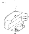
- Fig. 1 is a view illustrating an appearance of a charging device of a robot cleaner according to an embodiment
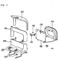
- Fig. 2 is an exploded perspective view illustrating the charging device of a robot cleaner according to the embodiment.
- a robot cleaner charging device 1 includes a main body 10.
- the main body 10 includes a base 300, a front cover 400, a return induction unit 100, and an upper cover 500, which are described hereinafter.
- the base 300 forms rear and bottom surfaces of the charging device 1, and provides a space where a terminal unit 200 described hereinafter and the return induction unit 100 are installed.
- the base 300 may include a coupling portion where at least the return induction unit 100 and the terminal unit 200 may be assembled or tentatively assembled. A portion of the return induction unit 100 or the terminal unit 200 may be coupled with the coupling portion via insertion or a coupling member.
- the terminal unit 200 supplies power to a robot cleaner by using a power source such as a commercial power source or a battery and, if necessary, through a conversion process to meet a working voltage of the robot cleaner.
- a power source such as a commercial power source or a battery
- the terminal unit 200 includes a converter (not illustrated) for voltage conversion, and power supplied from the converter is transmitted to a charging terminal 220 described hereinafter.
- the charging terminal 220 comes into contact with a power terminal of the robot cleaner to supply charging power to the robot cleaner, and is formed by bending a conductor with a low level of electric resistance, such as copper, several times.
- the charging terminal 220 formed through the bending process is installed such that at least a portion may be exposed outside the front cover 400 which is coupled with a front side of the base 300.
- a terminal supporting member 240 is disposed at the front cover 400 to support the charging terminal 220 between the base 300 and the front cover 400.
- Fig. 3 is a view illustrating the terminal unit of the robot cleaner charging device according to the embodiment.
- the terminal supporting member 240 is formed by plastic injection molding, through which a side of the terminal supporting member 400 coming into contact with the charging terminal 220 can have a shape corresponding to a bent portion of the charging terminal 220.
- the other side extends far backwards from the side coming into contact with the charging terminal 220, and then, is bent upwards to be coupled with a rear surface of the front cover 400.
- the charging terminal 220 When the exposed portion of the front cover 400 is applied with pressure by coming into contact with the power terminal of the robot cleaner, the charging terminal 220 is elastically supported by a material and shape of the terminal supporting member 240 and, therefore, the charging terminal 220 and the power terminal can remain in tight contact with each other.
- An upper portion of the front cover 400 has a shape corresponding to a shape of a side surface of the robot cleaner, and a lower portion of the front cover 400, which is disposed at a lower portion of the robot cleaner, extends far forward so that the power terminal and the charging terminal 220 can be connected to each other.
- a terminal exposure hole 420 is formed at the lower portion of the front cover 400 so that the bent portion of the charging terminal 220 can be exposed, and a side portion of the front cover 400 which extends backwards from the upper and lower portions provides a space where a return induction unit cover 120 described hereinafter and the upper cover 500 can be installed.
- the return induction unit cover 120 which covers the side portion of the front cover 400 in part, is inserted into the front cover 400. When the insertion is completed, a front surface of the return induction unit cover 120 is disposed at the upper portion of the front cover 400.
- the return induction unit cover 120 installed at the abovementioned position is formed of a transparent or semitransparent material so that a return induction signal, which is transmitted by an induction signal generating unit 160 described hereinafter, can penetrate the return induction unit cover 120.
- the induction signal generating unit 160 which is a group of infrared sensors, leads the robot cleaner to return to the charging device following a transmitted infrared signal.
- the induction signal generating unit 160 is inserted into a printed circuit board 180 between the base 300 and the front cover 400, and disposed at a rear side of the return induction unit cover 120.
- An induction signal guide member 140 is further disposed between the induction signal generating unit 160 and the return induction unit cover 120 to improve linearity of the return induction signal by limiting a transmission angle of the return induction signal transmitted by the induction signal generating unit 160.
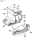
- Fig. 4 is a view illustrating a state in which the induction signal guide member that is a main component is installed according to the embodiment
- Fig. 5 is a bottom view illustrating a state in which the induction signal guide member of Fig. 4 is installed.
- the induction signal generating unit 160 includes access induction sensors 162 which transmit an infrared signal to lead the robot cleaner in a remote location to the charging device 1, and a docking induction sensor 164 leading the robot cleaner to a docking position when the robot cleaner is moved close to the charging device 1 by the access induction sensors 162.
- One or more access induction sensors 162 may be disposed at each of both sides, and one or more docking induction sensors 164 may be disposed between the access induction sensors 162.
- the induction signal guide member 140 which may have a T shape, limit the transmission angle of the signal transmitted by the docking induction sensor 164 and the access induction sensor 162.
- the induction signal guide member 140 protrudes forward, i.e., in a direction of a guiding signal transmitted by the induction signal generating unit 160 as illustrated in Fig. 5 .
- the length of the protrusion is equivalent to the distance between the printed circuit board 180 and the return induction unit cover 120 installed at the front cover 400.
- a guide 142 Disposed at a center of the induction signal guide member 140 is a guide 142, which surrounds the docking induction sensor 164 and has a front opening.
- a docking induction signal transmitted outside from the docking induction sensor 164 can be transmitted only through the front opening of the guide 142.
- the reflection unit 144 Disposed in the guide 142 are a plurality of reflection units 144 to further improve the linearity by limiting the transmission angle of the docking induction signal transmitted through the front opening.
- the reflection unit 144 may have a shape of an inwardly protruding plate or projection.
- the reflection unit 144 protrudes inwardly from an inner left side or an inner right side of the guide 142.
- the reflection units 144 form a series of layers including at least end and central portions of the guide 142 and the vicinity of the docking induction sensor 164.
- the reflection units 144 protrude inwardly from both inner sides of the guide 142, and ends of the reflection units 144 facing each other are disposed away from each other at a predetermined distance.
- a pair of the reflection units 144 facing each other form a layer, and the layer has a central opening to provide an optical path to the light transmitted by the docking induction sensor 164.
- the opening between the reflection units 144 formed in the abovementioned manner is formed on the same line as the docking induction sensor 164.
- the docking induction signal transmitted by the docking induction sensor 164 can pass through the opening between the reflection units 144 only when the transmission angle toward the opening is relatively narrow.
- the signal is blocked by the reflection units 144 and the transmission is blocked.
- the docking induction signal transmitted toward a side of the reflection unit 144 may be transmitted outside the guide 142 bumping into and reflected by the end of the reflection unit 144. To prevent the phenomenon, the end of the reflection unit 144 slopes.
- each of the reflection units 144 slopes toward the opened front side of the guide 142.
- a surface of the reflection unit 144 toward the opened front side of the guide 142 is longer than a surface of the reflection unit 144 toward the docking induction sensor 164 so that the side of the reflection unit 144 slopes.
- the docking induction signal which is transmitted toward the slope of the end is not transmitted outside but blocked inside the guide 142 because the reflection angle is toward the docking induction sensor 164.
- the signal which is transmitted outside the guide 142 has a relatively narrow transmission angle.
- the robot cleaner moves to an area where the return signals transmitted by the access induction sensors 162 interact and then receives the docking induction signal.
- Fig. 6 Illustrated in Fig. 6 for detailed description is the area of the induction signals generated by the charging device according to the embodiment.
- the signals transmitted by the return induction unit 100 toward the robot cleaner include the return induction signal to guide the robot cleaner toward the charging device 1 by using the access induction sensors 162 and the docking induction signal to lead the robot cleaner and the charging device 1 for docking by using the docking induction sensor 164.
- the return induction signal controls rotation of wheels of the robot cleaner in accordance with the direction of transmission, and reduces the distance of the robot cleaner moving sideways.
- the access induction sensor 162 is provided in plurality, with the docking induction sensor 164 disposed between the access induction sensors 162, and the access induction sensors 162 transmit the return induction signals at a relatively wide angle. Therefore, access induction areas 162' where the access induction sensors 162 guide the robot cleaner to return may overlap in part as illustrated in Fig. 5 .
- the docking induction signal guides the robot cleaner to allow the robot cleaner to dock with the charging device and the power terminal to come into contact with the charging terminal 220.
- the docking induction signal transmitted outside by the docking induction sensor 164 having the abovementioned purpose has a limited transmission angle because of the induction signal guide member 140.
- the guide 142 and the reflection plate 144 block the docking induction signal having a wide transmission angle while exposing the docking induction signal have a narrow transmission angle, and a docking induction area 164' thereby has a relatively very narrow width.
- the docking induction area 164' may be disposed toward the overlapped part of the access induction areas 162' with the docking induction sensor 164 and the guide 142 disposed between the access induction sensors 162.
- the robot cleaner approaches the docking induction area 164'. After approaching the docking induction area 164', the robot cleaner is guided by the docking induction signal and moved to the charging device.
- the narrow transmission angle of the docking induction signal reduces the lateral distance of the robot cleaner moving on the path to the charging device.
- the robot cleaner When the battery of the robot cleaner runs out while the robot cleaner moves in a pre-set cleaning area carrying out cleaning or when the cleaning is completed, the robot cleaner returns to the charging device 1 to recharge the battery.
- the robot cleaner transmits a signal to the charging device 1 when the battery runs out or the cleaning is completed, requesting return induction, and the signal is received by the return induction unit 100 of the charging device 1.
- the charging device 1 transmits the return induction signal through the access induction sensor 162 which constitutes a part of the induction signal generating unit 160.
- the robot cleaner detecting the return induction signal, moves toward the charging device 1 following the return induction signal.
- the rotation of the wheels of the robot cleaner is controlled, in accordance with the direction of the received return induction signal, i.e., the position of the access induction sensor 162 which forms the access induction area 162', so that the robot cleaner can move to the overlapped part of the access induction areas 162' generated by the access induction sensor 162.
- the robot cleaner moves to the charging device 1 following a docking guide signal transmitted by the docking induction sensor 164.
- the transmission angle of the docking guide signal transmitted by the docking induction sensor 164 is limited by the induction signal guide member 140, and the width of the docking induction area 164' is narrowed.
- the power terminal of the robot cleaner comes into stable contact with the charging terminal 220 of the charging device 1.
- the terminal supporting member 240 which is disposed at the lower side of the charging terminal 220, elastically supports the charging terminal 220 so that the power terminal and the charging terminal 220 can remain in tight contact with each other and the docked robot cleaner can be recharged stably.
- the charging device can reduce the transmission angle of the docking guide signal transmitted by the docking induction sensor, and increase the accuracy with which the robot cleaner is docked with the charging device.
- the power terminal of the docked robot cleaner and the charging terminal of the charging device can remain in tight contact with each other because the charging terminal is elastically supported.
- the charging device can charge the robot cleaner efficiently.
- a charging device of a robot cleaner comprising: a main body comprising a terminal unit configured to charge the robot cleaner, the main body defining an appearance; an induction signal generating unit disposed at a side of the main body to transmit a return induction signal to the robot cleaner; and an induction signal guide member disposed at a side of the induction signal generating unit to enhance docking performance of the robot cleaner by improving linearity of the induction signal.
- the induction signal generating unit may comprise at least a pair of access induction sensors transmitting a signal for guiding the robot cleaner to a return position, and at least one docking induction sensor guiding the robot cleaner to a docking position by transmitting a docking induction signal to an area where the signals transmitted by the access induction sensors intersect.
- the induction signal guide member may improve the linearity by restricting a transmission angle of the signal transmitted from the docking induction sensor.
- the induction signal guide member may comprise a guide which is opened at a front side and surrounds at least both sides of the docking induction sensor.
- a plurality of reflections units may be disposed in the guide to block the docking induction signal, the transmission angle of which is relatively large, from being transmitted outwards.
- the reflection units may be spaced a predetermined distance from each other.
- the reflection units may protrude from both inner sides of the guide to face each other, a space between the reflection units facing each other being disposed on the same line as the docking induction sensor.
- An end of the reflection unit may slope.
- a surface of each of the reflection units which is toward the docking induction sensor may have a shorter projection length than a surface of each of the reflection units which is toward the opened front side of the guide.
- each of the reflection units may slope toward the opened front side.
Landscapes
- Engineering & Computer Science (AREA)
- Mechanical Engineering (AREA)
- Physics & Mathematics (AREA)
- Aviation & Aerospace Engineering (AREA)
- Radar, Positioning & Navigation (AREA)
- Remote Sensing (AREA)
- General Physics & Mathematics (AREA)
- Automation & Control Theory (AREA)
- Robotics (AREA)
- Electromagnetism (AREA)
- Human Computer Interaction (AREA)
- Electric Vacuum Cleaner (AREA)
- Charge And Discharge Circuits For Batteries Or The Like (AREA)
- Control Of Position, Course, Altitude, Or Attitude Of Moving Bodies (AREA)
Description
- The present disclosure relates to a charging device of a robot cleaner.
- A general robot cleaner moves within a certain area on its own and without user control -to remove dust and foreign substances from the floor of the area. The robot cleaner uses a sensor or a camera to locate walls and obstacles, and cleans up the area avoiding the walls and obstacles by using the data obtained by the sensor or the camera.
-
- For the abovementioned purpose, the robot cleaner has to be equipped with a battery which supplies power to move the robot cleaner. Usually, when used up, the battery is recharged for reuse.
- Therefore, the robot cleaner has to be provided to its user along with a charging device, which has the function of return induction signal generation so that the robot cleaner with a dead battery can return to the charging device for recharging.
- When receiving the return induction signal generated by the charging device, the robot cleaner moves toward the charging device by following the return induction signal.
- After approaching the charging device, the robot cleaner docks with the charging device so that the power supply terminal is connected to the charging terminal of the charging device. Once the docking is completed, power is supplied through the charging terminal to charge the battery of the robot cleaner.
- In order for the robot cleaner to be charged effectively, the power supply terminal of the robot cleaner and the charging terminal of the charging device have to be connected accurately to each other. To that end, the docking path has to be guided without inaccuracy.
- Further, the contact force between the power supply and charging terminals needs to be increased because the charging can be carried out effectively only when the terminals remain in tight contact with each other.
- Embodiments provide a charging device of a robot cleaner which guides a return induction signal accurately to a robot cleaner.
- Embodiments also provide a charging device of a robot cleaner which allows a power terminal of a robot cleaner in docking with the charging device and a charging terminal of the charging device to remain in tight contact with each other.
- In one embodiment, a charging device of a robot cleaner includes: at least one cover defining an appearance of the charging device; a base which is coupled with the cover and includes a terminal unit for charging the robot cleaner; an induction signal generating unit disposed at a side of the cover or the base to transmit a return induction signal to the robot cleaner; and an induction signal guide member disposed at a side of the induction signal generating unit to enhance a docking performance of the robot cleaner by improving linearity of the induction signal.
- The details of one or more embodiments are set forth in the accompanying drawings and the description below. Other features will be apparent from the description and drawings, and from the claims.
-
-
Fig. 1 is a view illustrating an appearance of a charging device of a robot cleaner according to an embodiment. -
Fig. 2 is an exploded perspective view illustrating the charging device of a robot cleaner according to an embodiment. -
Fig. 3 is a view illustrating a terminal unit of the charging device of a robot cleaner according to an embodiment. -
Fig. 4 is a view illustrating a state in which an induction signal guide member that is a main component is installed according to an embodiment. -
Fig. 5 is a bottom view illustrating a state in which the induction signal guide member ofFig. 4 is installed. -
Fig. 6 is a view illustrating an area of an induction signal generated by the charging device of a robot cleaner according to an embodiment. - A charging device of a robot cleaner according to an embodiment will be described in detail with reference to the accompanying drawings. The invention may, however, be embodied in many different forms and should not be construed as being limited to the embodiments set forth herein; rather, that alternate embodiments included in other retrogressive inventions or falling within the spirit and scope of the present disclosure can easily be derived through adding, altering, and changing, and will fully convey the concept of the invention to those skilled in the art.
-
Fig. 1 is a view illustrating an appearance of a charging device of a robot cleaner according to an embodiment, andFig. 2 is an exploded perspective view illustrating the charging device of a robot cleaner according to the embodiment. - As illustrated in the drawings, a robot
cleaner charging device 1 according to an embodiment includes amain body 10. Themain body 10 includes abase 300, afront cover 400, areturn induction unit 100, and anupper cover 500, which are described hereinafter. - The
base 300 forms rear and bottom surfaces of thecharging device 1, and provides a space where aterminal unit 200 described hereinafter and thereturn induction unit 100 are installed. - Although not illustrated, the
base 300 may include a coupling portion where at least thereturn induction unit 100 and theterminal unit 200 may be assembled or tentatively assembled. A portion of thereturn induction unit 100 or theterminal unit 200 may be coupled with the coupling portion via insertion or a coupling member. - The
terminal unit 200 supplies power to a robot cleaner by using a power source such as a commercial power source or a battery and, if necessary, through a conversion process to meet a working voltage of the robot cleaner. - Therefore, the
terminal unit 200 includes a converter (not illustrated) for voltage conversion, and power supplied from the converter is transmitted to acharging terminal 220 described hereinafter. - The
charging terminal 220 comes into contact with a power terminal of the robot cleaner to supply charging power to the robot cleaner, and is formed by bending a conductor with a low level of electric resistance, such as copper, several times. - The
charging terminal 220 formed through the bending process is installed such that at least a portion may be exposed outside thefront cover 400 which is coupled with a front side of thebase 300. To that end, a terminal supportingmember 240 is disposed at thefront cover 400 to support thecharging terminal 220 between thebase 300 and thefront cover 400. -
Fig. 3 is a view illustrating the terminal unit of the robot cleaner charging device according to the embodiment. - As illustrated in the drawing, the terminal supporting
member 240 is formed by plastic injection molding, through which a side of theterminal supporting member 400 coming into contact with thecharging terminal 220 can have a shape corresponding to a bent portion of thecharging terminal 220. - The other side extends far backwards from the side coming into contact with the
charging terminal 220, and then, is bent upwards to be coupled with a rear surface of thefront cover 400. - When the exposed portion of the
front cover 400 is applied with pressure by coming into contact with the power terminal of the robot cleaner, thecharging terminal 220 is elastically supported by a material and shape of theterminal supporting member 240 and, therefore, thecharging terminal 220 and the power terminal can remain in tight contact with each other. - An upper portion of the
front cover 400 has a shape corresponding to a shape of a side surface of the robot cleaner, and a lower portion of thefront cover 400, which is disposed at a lower portion of the robot cleaner, extends far forward so that the power terminal and thecharging terminal 220 can be connected to each other. - A
terminal exposure hole 420 is formed at the lower portion of thefront cover 400 so that the bent portion of thecharging terminal 220 can be exposed, and a side portion of thefront cover 400 which extends backwards from the upper and lower portions provides a space where a returninduction unit cover 120 described hereinafter and theupper cover 500 can be installed. - The return
induction unit cover 120, which covers the side portion of thefront cover 400 in part, is inserted into thefront cover 400. When the insertion is completed, a front surface of the returninduction unit cover 120 is disposed at the upper portion of thefront cover 400. - The return
induction unit cover 120 installed at the abovementioned position is formed of a transparent or semitransparent material so that a return induction signal, which is transmitted by an inductionsignal generating unit 160 described hereinafter, can penetrate the returninduction unit cover 120. - The induction
signal generating unit 160, which is a group of infrared sensors, leads the robot cleaner to return to the charging device following a transmitted infrared signal. The inductionsignal generating unit 160 is inserted into a printedcircuit board 180 between thebase 300 and thefront cover 400, and disposed at a rear side of the returninduction unit cover 120. - An induction
signal guide member 140 is further disposed between the inductionsignal generating unit 160 and the returninduction unit cover 120 to improve linearity of the return induction signal by limiting a transmission angle of the return induction signal transmitted by the inductionsignal generating unit 160. -
Fig. 4 is a view illustrating a state in which the induction signal guide member that is a main component is installed according to the embodiment, andFig. 5 is a bottom view illustrating a state in which the induction signal guide member ofFig. 4 is installed. - As illustrated in the drawings, the induction
signal generating unit 160 includesaccess induction sensors 162 which transmit an infrared signal to lead the robot cleaner in a remote location to thecharging device 1, and adocking induction sensor 164 leading the robot cleaner to a docking position when the robot cleaner is moved close to thecharging device 1 by theaccess induction sensors 162. - One or more
access induction sensors 162 may be disposed at each of both sides, and one or moredocking induction sensors 164 may be disposed between theaccess induction sensors 162. - The induction
signal guide member 140, which may have a T shape, limit the transmission angle of the signal transmitted by thedocking induction sensor 164 and theaccess induction sensor 162. - In a state when the induction
signal guide member 140 is installed at the printedcircuit board 180, the inductionsignal guide member 140 protrudes forward, i.e., in a direction of a guiding signal transmitted by the inductionsignal generating unit 160 as illustrated inFig. 5 . The length of the protrusion is equivalent to the distance between the printedcircuit board 180 and the returninduction unit cover 120 installed at thefront cover 400. - Disposed at a center of the induction
signal guide member 140 is aguide 142, which surrounds thedocking induction sensor 164 and has a front opening. - Therefore, a docking induction signal transmitted outside from the
docking induction sensor 164 can be transmitted only through the front opening of theguide 142. - Disposed in the
guide 142 are a plurality of reflection units 144 to further improve the linearity by limiting the transmission angle of the docking induction signal transmitted through the front opening. The reflection unit 144 may have a shape of an inwardly protruding plate or projection. - The reflection unit 144 protrudes inwardly from an inner left side or an inner right side of the
guide 142. The reflection units 144 form a series of layers including at least end and central portions of theguide 142 and the vicinity of thedocking induction sensor 164. - In other words, the reflection units 144 protrude inwardly from both inner sides of the
guide 142, and ends of the reflection units 144 facing each other are disposed away from each other at a predetermined distance. - Therefore, a pair of the reflection units 144 facing each other form a layer, and the layer has a central opening to provide an optical path to the light transmitted by the
docking induction sensor 164. - The opening between the reflection units 144 formed in the abovementioned manner is formed on the same line as the
docking induction sensor 164. - Therefore, the docking induction signal transmitted by the
docking induction sensor 164 can pass through the opening between the reflection units 144 only when the transmission angle toward the opening is relatively narrow. When the transmission angle is relatively wide, the signal is blocked by the reflection units 144 and the transmission is blocked. - Since the reflection unit 144 has a predetermined thickness, the docking induction signal transmitted toward a side of the reflection unit 144 may be transmitted outside the
guide 142 bumping into and reflected by the end of the reflection unit 144. To prevent the phenomenon, the end of the reflection unit 144 slopes. - The end of each of the reflection units 144 slopes toward the opened front side of the
guide 142. - In other words, a surface of the reflection unit 144 toward the opened front side of the
guide 142 is longer than a surface of the reflection unit 144 toward thedocking induction sensor 164 so that the side of the reflection unit 144 slopes. - The docking induction signal which is transmitted toward the slope of the end is not transmitted outside but blocked inside the
guide 142 because the reflection angle is toward thedocking induction sensor 164. - Therefore, the signal which is transmitted outside the
guide 142 has a relatively narrow transmission angle. To receive the signal, the robot cleaner moves to an area where the return signals transmitted by theaccess induction sensors 162 interact and then receives the docking induction signal. - Illustrated in
Fig. 6 for detailed description is the area of the induction signals generated by the charging device according to the embodiment. - As illustrated in the drawing, the signals transmitted by the
return induction unit 100 toward the robot cleaner include the return induction signal to guide the robot cleaner toward the chargingdevice 1 by using theaccess induction sensors 162 and the docking induction signal to lead the robot cleaner and thecharging device 1 for docking by using thedocking induction sensor 164. - In guiding the robot cleaner to the charging device, the return induction signal controls rotation of wheels of the robot cleaner in accordance with the direction of transmission, and reduces the distance of the robot cleaner moving sideways.
- To this end, the
access induction sensor 162 is provided in plurality, with thedocking induction sensor 164 disposed between theaccess induction sensors 162, and theaccess induction sensors 162 transmit the return induction signals at a relatively wide angle. Therefore, access induction areas 162' where theaccess induction sensors 162 guide the robot cleaner to return may overlap in part as illustrated inFig. 5 . - Meanwhile, the docking induction signal guides the robot cleaner to allow the robot cleaner to dock with the charging device and the power terminal to come into contact with the charging
terminal 220. - The docking induction signal transmitted outside by the
docking induction sensor 164 having the abovementioned purpose has a limited transmission angle because of the inductionsignal guide member 140. - In other words, the
guide 142 and the reflection plate 144 block the docking induction signal having a wide transmission angle while exposing the docking induction signal have a narrow transmission angle, and a docking induction area 164' thereby has a relatively very narrow width. - The docking induction area 164' may be disposed toward the overlapped part of the access induction areas 162' with the
docking induction sensor 164 and theguide 142 disposed between theaccess induction sensors 162. - Returning to the charging device heading toward the overlapped part of the access induction areas 162', the robot cleaner approaches the docking induction area 164'. After approaching the docking induction area 164', the robot cleaner is guided by the docking induction signal and moved to the charging device.
- Here, the narrow transmission angle of the docking induction signal reduces the lateral distance of the robot cleaner moving on the path to the charging device.
- Since the lateral movement of the robot cleaner is reduced during the docking process, the docking accuracy can increase.
- Described hereinafter is the process in which the robot cleaner returns to the
charging device 1 having the abovementioned structure. - When the battery of the robot cleaner runs out while the robot cleaner moves in a pre-set cleaning area carrying out cleaning or when the cleaning is completed, the robot cleaner returns to the
charging device 1 to recharge the battery. - For the purpose, the robot cleaner transmits a signal to the
charging device 1 when the battery runs out or the cleaning is completed, requesting return induction, and the signal is received by thereturn induction unit 100 of thecharging device 1. - When the signal from the robot cleaner is received, the charging
device 1 transmits the return induction signal through theaccess induction sensor 162 which constitutes a part of the inductionsignal generating unit 160. The robot cleaner, detecting the return induction signal, moves toward the chargingdevice 1 following the return induction signal. - During the abovementioned process, the rotation of the wheels of the robot cleaner is controlled, in accordance with the direction of the received return induction signal, i.e., the position of the
access induction sensor 162 which forms the access induction area 162', so that the robot cleaner can move to the overlapped part of the access induction areas 162' generated by theaccess induction sensor 162. - When the robot cleaner reaches the overlapped part of the access induction areas 162', the robot cleaner moves to the
charging device 1 following a docking guide signal transmitted by thedocking induction sensor 164. - Here, the transmission angle of the docking guide signal transmitted by the
docking induction sensor 164 is limited by the inductionsignal guide member 140, and the width of the docking induction area 164' is narrowed. - Therefore, the lateral movement of the robot cleaner depending on the direction in which the docking induction signal is received is reduced, and the robot cleaner docks with the charging
device 1 showing an increasingly linear movement as the robot cleaner approaches thecharging device 1. - Via the abovementioned docking induction, the power terminal of the robot cleaner comes into stable contact with the charging
terminal 220 of thecharging device 1. - The
terminal supporting member 240, which is disposed at the lower side of the chargingterminal 220, elastically supports the chargingterminal 220 so that the power terminal and the chargingterminal 220 can remain in tight contact with each other and the docked robot cleaner can be recharged stably. - When the recharging of the robot cleaner is completed and the robot cleaner is removed from the charging
device 1 for such reasons as cleaning or storage, the strength of stability of theterminal supporting member 240 comes into play and the chargingterminal 220 returns to the position of initial exposure. - The charging device according to the embodiment can reduce the transmission angle of the docking guide signal transmitted by the docking induction sensor, and increase the accuracy with which the robot cleaner is docked with the charging device.
- Also, at the terminal unit, the power terminal of the docked robot cleaner and the charging terminal of the charging device can remain in tight contact with each other because the charging terminal is elastically supported.
- Therefore, the charging device according to the embodiment can charge the robot cleaner efficiently.
- Although embodiments have been described with reference to a number of illustrative embodiments thereof, it should be understood that numerous other modifications and embodiments can be devised by those skilled in the art that will fall within the scope of the principles of this disclosure. More particularly, various variations and modifications are possible in the component parts and/or arrangements of the subject combination arrangement within the scope of the disclosure, the drawings and the appended claims. In addition to variations and modifications in the component parts and/or arrangements, alternative uses will also be apparent to those skilled in the art.
- There is disclosed a charging device of a robot cleaner, the charging device comprising: a main body comprising a terminal unit configured to charge the robot cleaner, the main body defining an appearance; an induction signal generating unit disposed at a side of the main body to transmit a return induction signal to the robot cleaner; and an induction signal guide member disposed at a side of the induction signal generating unit to enhance docking performance of the robot cleaner by improving linearity of the induction signal.
- The induction signal generating unit may comprise at least a pair of access induction sensors transmitting a signal for guiding the robot cleaner to a return position, and at least one docking induction sensor guiding the robot cleaner to a docking position by transmitting a docking induction signal to an area where the signals transmitted by the access induction sensors intersect.
- The induction signal guide member may improve the linearity by restricting a transmission angle of the signal transmitted from the docking induction sensor.
- The induction signal guide member may comprise a guide which is opened at a front side and surrounds at least both sides of the docking induction sensor.
- A plurality of reflections units may be disposed in the guide to block the docking induction signal, the transmission angle of which is relatively large, from being transmitted outwards.
- The reflection units may be spaced a predetermined distance from each other.
- The reflection units may protrude from both inner sides of the guide to face each other, a space between the reflection units facing each other being disposed on the same line as the docking induction sensor.
- An end of the reflection unit may slope.
- A surface of each of the reflection units which is toward the docking induction sensor may have a shorter projection length than a surface of each of the reflection units which is toward the opened front side of the guide.
- The end of each of the reflection units may slope toward the opened front side.
Claims (9)
- A charging device of a robot cleaner, the charging device comprising:a main body (10) comprising a terminal unit (200) configured to charge the robot cleaner, the main body defining an appearance;an induction signal generating unit (160) disposed at a side of the main body (10) and arranged to transmit a return induction signal to the robot cleaner; andan induction signal guide member (140) disposed at a side of the induction signal generating unit (160) and arranged to enhance docking performance of the robot cleaner by improving linearity of the induction signal,wherein the induction signal generating unit (160) comprises at least a pair of access induction sensors (162) arranged to transmit a signal for guiding the robot cleaner to a return position, and at least one docking induction sensor (164) arranged to guide the robot cleaner to a docking position by transmitting a docking induction signal, wherein the docking induction sensor is disposed between the access induction sensors,wherein the induction signal guide member (140) comprises a guide (142) which surrounds the docking induction sensor (164),characterizied in that the induction signal guide member (140) further comprises a pair of reflection units (144) facing each other to form a layer which has a central opening providing an optical path to the docking induction signal transmitted by the docking induction sensor (164), the pair of reflection units being arranged to narrow the transmission angle of the docking induction signal.
- The charging device according to claim 1, wherein the pair of reflection units (144) are spaced a predetermined distance from each other.
- The charging device according to claim 1, wherein the central opening is disposed on the same line as the docking induction sensor (164).
- The charging device according to claim 1, wherein the one docking induction sensor (164) is configured for transmitting the docking induction signal to an area where the signals transmitted by the access induction sensors (162) overlap.
- The charging device according to claim 1, wherein a surface of each of the pair of reflection units (144) which is toward the docking induction sensor (164) has a shorter projection length than a surface of each of the pair of reflection units (144) which is toward an opened front side of the guide (142).
- A robot cleaner arranged to receive an induction signal from the charging device of any preceding claim and dock with the charging device.
- A system comprising a charging device as claimed in any of claims 1 to 5 and a robot cleaner as claimed in claim 6.
- A method of docking a robot cleaner with a charging device, the method comprising:the charging device transmitting a return induction signal using a plurality of access induction sensors (162) of an induction signal generating unit (160);the charging device transmitting a docking induction signal, using a docking induction sensor (164) of the induction signal generating unit (160);improving the linearity of the docking induction signal using an induction signal guide member (140) of the charging device;the robot cleaner receiving the return induction signal; andguiding the path of the robot cleaner to a return position using the return induction signal,wherein the induction signal guide member (140) comprises: a guide (142) which surrounds the docking induction sensor (164); and a pair of reflection units (144) facing each other to form a layer which has a central opening providing an optical path to the docking induction signal transmitted by the docking induction sensor (164), the pair of reflection units being arranged to narrow the transmission angle of the docking induction signal.
- The method of claim 8, further comprising:the robot cleaner receiving the docking induction signal; andguiding the robot cleaner to a docking position using the docking induction signal.
Priority Applications (2)
| Application Number | Priority Date | Filing Date | Title |
|---|---|---|---|
| EP19202567.4A EP3632283B1 (en) | 2009-06-30 | 2009-06-30 | Charging device of robot cleaner |
| ES19202567T ES2872015T3 (en) | 2009-06-30 | 2009-06-30 | Cleaning robot charging device |
Applications Claiming Priority (4)
| Application Number | Priority Date | Filing Date | Title |
|---|---|---|---|
| EP15184935.3A EP2982286B1 (en) | 2009-06-30 | 2009-06-30 | Charging device of robot cleaner and method for docking a robot cleaner to the charging device |
| EP19202567.4A EP3632283B1 (en) | 2009-06-30 | 2009-06-30 | Charging device of robot cleaner |
| EP09846851.5A EP2449938B1 (en) | 2009-06-30 | 2009-06-30 | Charging device of robot cleaner |
| PCT/KR2009/003560 WO2011002112A1 (en) | 2009-06-30 | 2009-06-30 | Charging device of robot cleaner |
Related Parent Applications (3)
| Application Number | Title | Priority Date | Filing Date |
|---|---|---|---|
| EP09846851.5A Division EP2449938B1 (en) | 2009-06-30 | 2009-06-30 | Charging device of robot cleaner |
| EP15184935.3A Division EP2982286B1 (en) | 2009-06-30 | 2009-06-30 | Charging device of robot cleaner and method for docking a robot cleaner to the charging device |
| EP15184935.3A Division-Into EP2982286B1 (en) | 2009-06-30 | 2009-06-30 | Charging device of robot cleaner and method for docking a robot cleaner to the charging device |
Publications (2)
| Publication Number | Publication Date |
|---|---|
| EP3632283A1 EP3632283A1 (en) | 2020-04-08 |
| EP3632283B1 true EP3632283B1 (en) | 2021-02-24 |
Family
ID=43411177
Family Applications (4)
| Application Number | Title | Priority Date | Filing Date |
|---|---|---|---|
| EP19202567.4A Active EP3632283B1 (en) | 2009-06-30 | 2009-06-30 | Charging device of robot cleaner |
| EP15184935.3A Active EP2982286B1 (en) | 2009-06-30 | 2009-06-30 | Charging device of robot cleaner and method for docking a robot cleaner to the charging device |
| EP09846851.5A Active EP2449938B1 (en) | 2009-06-30 | 2009-06-30 | Charging device of robot cleaner |
| EP15179575.4A Active EP2992802B1 (en) | 2009-06-30 | 2009-06-30 | Charging device of robot cleaner |
Family Applications After (3)
| Application Number | Title | Priority Date | Filing Date |
|---|---|---|---|
| EP15184935.3A Active EP2982286B1 (en) | 2009-06-30 | 2009-06-30 | Charging device of robot cleaner and method for docking a robot cleaner to the charging device |
| EP09846851.5A Active EP2449938B1 (en) | 2009-06-30 | 2009-06-30 | Charging device of robot cleaner |
| EP15179575.4A Active EP2992802B1 (en) | 2009-06-30 | 2009-06-30 | Charging device of robot cleaner |
Country Status (5)
| Country | Link |
|---|---|
| US (3) | US8825256B2 (en) |
| EP (4) | EP3632283B1 (en) |
| KR (1) | KR101428846B1 (en) |
| ES (3) | ES2563087T3 (en) |
| WO (1) | WO2011002112A1 (en) |
Families Citing this family (46)
| Publication number | Priority date | Publication date | Assignee | Title |
|---|---|---|---|---|
| US8825256B2 (en) * | 2009-06-30 | 2014-09-02 | Lg Electronics Inc. | Charging device of robot cleaner |
| KR101192540B1 (en) * | 2010-12-20 | 2012-10-17 | (주)마미로봇 | Multifunction charger for wireless cleaner |
| US9280158B2 (en) | 2012-06-07 | 2016-03-08 | Koninklijke Philips N.V. | System and method for guiding a robot cleaner along a path |
| KR101437778B1 (en) * | 2013-05-06 | 2014-09-11 | (주)마미로봇 | Guide signal transmitter of docking station |
| WO2015002827A1 (en) * | 2013-07-01 | 2015-01-08 | BUDDIES, Step | System, apparatus, and method for measuring number of user steps |
| EP3211503B1 (en) * | 2014-10-23 | 2019-09-04 | Jiangsu Midea Cleaning Appliances Co., Ltd. | Charging base of cleaning robot, and cleaning robot |
| CN105581736B (en) * | 2014-10-23 | 2018-06-08 | 江苏美的清洁电器股份有限公司 | Sweeping robot and its cradle |
| USD818950S1 (en) * | 2015-06-30 | 2018-05-29 | Bobsweep Inc. | Charging station for a robotic vacuum |
| KR102174382B1 (en) * | 2016-05-26 | 2020-11-05 | 한국전자기술연구원 | Charging device for distribution transport robot and charging system using the same |
| KR101897730B1 (en) * | 2016-12-30 | 2018-09-12 | 엘지전자 주식회사 | Charging stating for robot cleaner |
| CN110113978B (en) * | 2016-12-30 | 2021-08-31 | Lg电子株式会社 | Robotic cleaner system including charging station |
| US10383499B2 (en) * | 2017-08-31 | 2019-08-20 | Irobot Corporation | Wet robot docking station |
| JP2020533056A (en) | 2017-09-07 | 2020-11-19 | シャークニンジャ オペレーティング エルエルシー | Robot cleaner |
| USD867987S1 (en) * | 2017-09-15 | 2019-11-26 | Beijing Rockrobo Technology Co., Ltd. | Base station |
| US12416917B1 (en) * | 2017-10-27 | 2025-09-16 | AI Incorporated | Autonomous shopping device |
| KR102476898B1 (en) | 2018-01-02 | 2022-12-13 | 엘지전자 주식회사 | Charging station |
| US11121567B2 (en) | 2018-03-09 | 2021-09-14 | AI Incorporated | Mobile robot charging station |
| CN108453748A (en) * | 2018-03-23 | 2018-08-28 | 国网上海市电力公司 | A kind of high pressure transformer and distribution power station cleaning auxiliary robot |
| KR102515485B1 (en) * | 2018-06-14 | 2023-03-29 | 삼성전자주식회사 | Charging station of robot cleaner |
| KR102137164B1 (en) | 2018-06-15 | 2020-07-24 | 엘지전자 주식회사 | Guidance robot |
| CN109066836B (en) * | 2018-07-16 | 2021-09-21 | 深圳市无限动力发展有限公司 | Charging device |
| US11583158B2 (en) | 2018-08-01 | 2023-02-21 | Sharkninja Operating Llc | Robotic vacuum cleaner |
| USD906236S1 (en) * | 2018-08-03 | 2020-12-29 | Techtronic Cordless Gp | Docking station for mowers |
| CN208621772U (en) * | 2018-08-24 | 2019-03-19 | 北京猎户星空科技有限公司 | Infrared transmitter and charging pile |
| CA3117300C (en) | 2018-10-22 | 2024-04-02 | Sharkninja Operating Llc | Docking station for robotic cleaner |
| UA41384S (en) * | 2019-03-18 | 2020-04-27 | Бейцзін Сяомі Мо | CHARGER FOR CLEANING DEVICE |
| USD951859S1 (en) * | 2019-08-15 | 2022-05-17 | Beijing Xiaomi Mobile Software Co., Ltd. | Charging base for robot vacuum cleaner |
| AU2020418666B2 (en) | 2019-12-30 | 2024-11-14 | Lg Electronics Inc. | Charging station for robot cleaner |
| EP4085809B1 (en) | 2019-12-30 | 2025-02-05 | LG Electronics Inc. | Robot vacuum charging station |
| KR102829278B1 (en) | 2019-12-30 | 2025-07-03 | 엘지전자 주식회사 | Charging apparatus for robot cleaner |
| CN112168081A (en) * | 2020-01-02 | 2021-01-05 | 尚科宁家(中国)科技有限公司 | Sweeper, sweeper replenishment system and replenishment station for sweeper |
| TWI716321B (en) * | 2020-05-27 | 2021-01-11 | 和碩聯合科技股份有限公司 | Charging device |
| US11553824B2 (en) * | 2020-06-25 | 2023-01-17 | Power Logic Tech, Inc. | Automatic guiding method for self-propelled apparatus |
| CN111920354A (en) * | 2020-09-08 | 2020-11-13 | 广州科语机器人有限公司 | A charging station and sweeping robot |
| USD965517S1 (en) * | 2020-10-19 | 2022-10-04 | Amazon Technologies, Inc. | Docking station |
| EP4070704B1 (en) * | 2021-04-08 | 2026-01-07 | Vorwerk & Co. Interholding GmbH | Base station for a floor treating device and system comprising a base station and floor treating device |
| CN115191866B (en) * | 2021-04-09 | 2024-07-05 | 美智纵横科技有限责任公司 | A recharging method, device, cleaning robot and storage medium |
| CN216221344U (en) * | 2021-07-16 | 2022-04-08 | 北京石头世纪科技股份有限公司 | Base station and cleaning robot system |
| KR102727384B1 (en) | 2021-10-29 | 2024-11-07 | 주식회사 제타뱅크 | Mobile robot charging system using a retroreflective plate when docking |
| US12589669B2 (en) * | 2021-12-15 | 2026-03-31 | Adata Technology Co., Ltd. | Charging station |
| KR102727342B1 (en) | 2021-12-24 | 2024-11-07 | 주식회사 제타뱅크 | Mobile robot charging system using lidar when docking |
| USD976826S1 (en) * | 2022-03-24 | 2023-01-31 | Guangyu Hua | Charger for robotic vacuum cleaner |
| USD980162S1 (en) * | 2022-03-24 | 2023-03-07 | Guangyu Hua | Charger for robotic vacuum cleaner |
| US20230369872A1 (en) * | 2022-05-12 | 2023-11-16 | Techtronic Cordless Gp | Robotic tool and charging station |
| CA224123S (en) * | 2023-03-02 | 2024-07-19 | Willand Beijing Tech Co Ltd | Charging station |
| KR102620640B1 (en) * | 2023-06-15 | 2024-01-03 | 주식회사 도구공간 | Robot docking station |
Family Cites Families (20)
| Publication number | Priority date | Publication date | Assignee | Title |
|---|---|---|---|---|
| US3784836A (en) * | 1972-10-06 | 1974-01-08 | Sybron Corp | Ir generator having ellipsoidal and paraboloidal reflectors |
| US4327972A (en) | 1979-10-22 | 1982-05-04 | Coulter Electronics, Inc. | Redirecting surface for desired intensity profile |
| US4679152A (en) * | 1985-02-20 | 1987-07-07 | Heath Company | Navigation system and method for a mobile robot |
| GB2248141A (en) * | 1990-09-18 | 1992-03-25 | Servomex | Infra-red source |
| AU1327899A (en) * | 1997-11-27 | 1999-06-16 | Solar & Robotics | Improvements to mobile robots and their control system |
| DE10231391A1 (en) | 2002-07-08 | 2004-02-12 | Alfred Kärcher Gmbh & Co. Kg | Tillage system |
| DE10261788B3 (en) * | 2002-12-23 | 2004-01-22 | Alfred Kärcher Gmbh & Co. Kg | Mobile tillage device |
| KR100656701B1 (en) | 2004-10-27 | 2006-12-13 | 삼성광주전자 주식회사 | Robot vacuum cleaner system and external charging device return method |
| KR100645381B1 (en) * | 2005-08-31 | 2006-11-14 | 삼성광주전자 주식회사 | External charge return device and return method for robot cleaner |
| KR100766435B1 (en) * | 2005-10-27 | 2007-10-15 | 엘지전자 주식회사 | Mobile robot charging station return system |
| KR100692897B1 (en) * | 2005-10-28 | 2007-03-12 | 엘지전자 주식회사 | Mobile robot |
| ES2706729T3 (en) * | 2005-12-02 | 2019-04-01 | Irobot Corp | Robot system |
| KR100766439B1 (en) * | 2006-03-29 | 2007-10-12 | 엘지전자 주식회사 | Mobile robot charging station return system |
| KR100769910B1 (en) * | 2006-09-11 | 2007-10-24 | 엘지전자 주식회사 | Mobile robot and its operation method |
| KR100820585B1 (en) * | 2006-10-25 | 2008-04-11 | 엘지전자 주식회사 | Mobile robot system and control method |
| KR20080051936A (en) * | 2006-12-07 | 2008-06-11 | 삼성광주전자 주식회사 | Robotic docking guidance device |
| KR20080060535A (en) * | 2006-12-27 | 2008-07-02 | 주식회사 유진로봇 | Automatic charging device of autonomous mobile robot and automatic charging method using the same |
| KR101473870B1 (en) * | 2009-06-19 | 2014-12-18 | 삼성전자 주식회사 | Cleaning device |
| KR101672787B1 (en) * | 2009-06-19 | 2016-11-17 | 삼성전자주식회사 | Robot cleaner and docking station and robot cleaner system having the same and control method thereof |
| US8825256B2 (en) * | 2009-06-30 | 2014-09-02 | Lg Electronics Inc. | Charging device of robot cleaner |
-
2009
- 2009-06-30 US US13/379,753 patent/US8825256B2/en not_active Ceased
- 2009-06-30 ES ES09846851.5T patent/ES2563087T3/en active Active
- 2009-06-30 EP EP19202567.4A patent/EP3632283B1/en active Active
- 2009-06-30 EP EP15184935.3A patent/EP2982286B1/en active Active
- 2009-06-30 US US14/864,563 patent/USRE47264E1/en active Active
- 2009-06-30 US US14/965,286 patent/USRE47265E1/en active Active
- 2009-06-30 EP EP09846851.5A patent/EP2449938B1/en active Active
- 2009-06-30 EP EP15179575.4A patent/EP2992802B1/en active Active
- 2009-06-30 WO PCT/KR2009/003560 patent/WO2011002112A1/en not_active Ceased
- 2009-06-30 KR KR1020117025679A patent/KR101428846B1/en active Active
- 2009-06-30 ES ES15184935T patent/ES2764108T3/en active Active
- 2009-06-30 ES ES19202567T patent/ES2872015T3/en active Active
Non-Patent Citations (1)
| Title |
|---|
| None * |
Also Published As
| Publication number | Publication date |
|---|---|
| KR20120019437A (en) | 2012-03-06 |
| EP2992802A3 (en) | 2016-03-23 |
| USRE47265E1 (en) | 2019-03-05 |
| ES2872015T3 (en) | 2021-11-02 |
| EP2449938A4 (en) | 2015-06-03 |
| USRE47264E1 (en) | 2019-03-05 |
| EP2982286A1 (en) | 2016-02-10 |
| EP2992802A2 (en) | 2016-03-09 |
| EP3632283A1 (en) | 2020-04-08 |
| WO2011002112A1 (en) | 2011-01-06 |
| ES2764108T3 (en) | 2020-06-02 |
| KR101428846B1 (en) | 2014-08-14 |
| ES2563087T3 (en) | 2016-03-10 |
| EP2449938B1 (en) | 2015-12-02 |
| EP2449938A1 (en) | 2012-05-09 |
| US20120143428A1 (en) | 2012-06-07 |
| EP2982286B1 (en) | 2019-11-20 |
| EP2992802B1 (en) | 2018-12-19 |
| US8825256B2 (en) | 2014-09-02 |
Similar Documents
| Publication | Publication Date | Title |
|---|---|---|
| EP3632283B1 (en) | Charging device of robot cleaner | |
| KR101672787B1 (en) | Robot cleaner and docking station and robot cleaner system having the same and control method thereof | |
| CN215348699U (en) | Docking station for autonomous floor cleaner | |
| US10613543B2 (en) | Robot cleaner system having charging station | |
| JP5860998B2 (en) | System and method for guiding a robot cleaner along a path | |
| US8253372B2 (en) | Charging system and charging apparatus thereof | |
| CN212574788U (en) | Sweeping robot and automatic cleaning system | |
| US20040130290A1 (en) | Automatic charging device and method of automatically travelling cleaner | |
| CN103948358B (en) | Docking station for robot cleaner | |
| US20110295447A1 (en) | Direction device and operation system utilizing the same | |
| JP2018007908A (en) | Autonomous traveling vacuum cleaner system and charging stand | |
| JP2018029054A (en) | Cleaner charging station | |
| KR101349208B1 (en) | Robot Cleaner having Function of Contact Sensing | |
| KR101851587B1 (en) | Sensor assembly for robot cleaner | |
| KR102422390B1 (en) | Measuring device for monitoring vehicle battery | |
| KR200366079Y1 (en) | Charging device for Robot vacuum cleaner | |
| KR102358758B1 (en) | Recharging apparatus for Robot Cleaner | |
| CN103595080A (en) | Charger of robot dust collector | |
| KR100531813B1 (en) | Docking system and method for mobile robot | |
| JP2018112799A (en) | Autonomously moving vacuum cleaner | |
| KR20250058254A (en) | Agv charging system | |
| CN212635721U (en) | Butt-joint structure of mobile robot and skip | |
| JP2025083890A (en) | Transport System | |
| CN114073451A (en) | Robot vacuums and automatic cleaning systems | |
| JP2024069587A (en) | Contact Structure |
Legal Events
| Date | Code | Title | Description |
|---|---|---|---|
| PUAI | Public reference made under article 153(3) epc to a published international application that has entered the european phase |
Free format text: ORIGINAL CODE: 0009012 |
|
| STAA | Information on the status of an ep patent application or granted ep patent |
Free format text: STATUS: REQUEST FOR EXAMINATION WAS MADE |
|
| 17P | Request for examination filed |
Effective date: 20191010 |
|
| AC | Divisional application: reference to earlier application |
Ref document number: 2982286 Country of ref document: EP Kind code of ref document: P Ref document number: 2449938 Country of ref document: EP Kind code of ref document: P |
|
| AK | Designated contracting states |
Kind code of ref document: A1 Designated state(s): AT BE BG CH CY CZ DE DK EE ES FI FR GB GR HR HU IE IS IT LI LT LU LV MC MK MT NL NO PL PT RO SE SI SK TR |
|
| RBV | Designated contracting states (corrected) |
Designated state(s): AT BE BG CH CY CZ DE DK EE ES FI FR GB GR HR HU IE IS IT LI LT LU LV MC MK MT NL NO PL PT RO SE SI SK TR |
|
| GRAP | Despatch of communication of intention to grant a patent |
Free format text: ORIGINAL CODE: EPIDOSNIGR1 |
|
| STAA | Information on the status of an ep patent application or granted ep patent |
Free format text: STATUS: GRANT OF PATENT IS INTENDED |
|
| RIC1 | Information provided on ipc code assigned before grant |
Ipc: G05D 1/12 20060101ALI20200831BHEP Ipc: A47L 9/28 20060101AFI20200831BHEP Ipc: A47L 11/24 20060101ALI20200831BHEP Ipc: B25J 13/08 20060101ALI20200831BHEP |
|
| INTG | Intention to grant announced |
Effective date: 20200918 |
|
| GRAS | Grant fee paid |
Free format text: ORIGINAL CODE: EPIDOSNIGR3 |
|
| GRAA | (expected) grant |
Free format text: ORIGINAL CODE: 0009210 |
|
| STAA | Information on the status of an ep patent application or granted ep patent |
Free format text: STATUS: THE PATENT HAS BEEN GRANTED |
|
| AC | Divisional application: reference to earlier application |
Ref document number: 2982286 Country of ref document: EP Kind code of ref document: P Ref document number: 2449938 Country of ref document: EP Kind code of ref document: P |
|
| AK | Designated contracting states |
Kind code of ref document: B1 Designated state(s): AT BE BG CH CY CZ DE DK EE ES FI FR GB GR HR HU IE IS IT LI LT LU LV MC MK MT NL NO PL PT RO SE SI SK TR |
|
| REG | Reference to a national code |
Ref country code: CH Ref legal event code: EP |
|
| REG | Reference to a national code |
Ref country code: DE Ref legal event code: R096 Ref document number: 602009063393 Country of ref document: DE |
|
| REG | Reference to a national code |
Ref country code: AT Ref legal event code: REF Ref document number: 1363434 Country of ref document: AT Kind code of ref document: T Effective date: 20210315 |
|
| REG | Reference to a national code |
Ref country code: IE Ref legal event code: FG4D |
|
| REG | Reference to a national code |
Ref country code: LT Ref legal event code: MG9D |
|
| REG | Reference to a national code |
Ref country code: NL Ref legal event code: MP Effective date: 20210224 |
|
| PG25 | Lapsed in a contracting state [announced via postgrant information from national office to epo] |
Ref country code: GR Free format text: LAPSE BECAUSE OF FAILURE TO SUBMIT A TRANSLATION OF THE DESCRIPTION OR TO PAY THE FEE WITHIN THE PRESCRIBED TIME-LIMIT Effective date: 20210525 Ref country code: FI Free format text: LAPSE BECAUSE OF FAILURE TO SUBMIT A TRANSLATION OF THE DESCRIPTION OR TO PAY THE FEE WITHIN THE PRESCRIBED TIME-LIMIT Effective date: 20210224 Ref country code: HR Free format text: LAPSE BECAUSE OF FAILURE TO SUBMIT A TRANSLATION OF THE DESCRIPTION OR TO PAY THE FEE WITHIN THE PRESCRIBED TIME-LIMIT Effective date: 20210224 Ref country code: BG Free format text: LAPSE BECAUSE OF FAILURE TO SUBMIT A TRANSLATION OF THE DESCRIPTION OR TO PAY THE FEE WITHIN THE PRESCRIBED TIME-LIMIT Effective date: 20210524 Ref country code: PT Free format text: LAPSE BECAUSE OF FAILURE TO SUBMIT A TRANSLATION OF THE DESCRIPTION OR TO PAY THE FEE WITHIN THE PRESCRIBED TIME-LIMIT Effective date: 20210624 Ref country code: NO Free format text: LAPSE BECAUSE OF FAILURE TO SUBMIT A TRANSLATION OF THE DESCRIPTION OR TO PAY THE FEE WITHIN THE PRESCRIBED TIME-LIMIT Effective date: 20210524 Ref country code: LT Free format text: LAPSE BECAUSE OF FAILURE TO SUBMIT A TRANSLATION OF THE DESCRIPTION OR TO PAY THE FEE WITHIN THE PRESCRIBED TIME-LIMIT Effective date: 20210224 |
|
| REG | Reference to a national code |
Ref country code: AT Ref legal event code: MK05 Ref document number: 1363434 Country of ref document: AT Kind code of ref document: T Effective date: 20210224 |
|
| PG25 | Lapsed in a contracting state [announced via postgrant information from national office to epo] |
Ref country code: LV Free format text: LAPSE BECAUSE OF FAILURE TO SUBMIT A TRANSLATION OF THE DESCRIPTION OR TO PAY THE FEE WITHIN THE PRESCRIBED TIME-LIMIT Effective date: 20210224 Ref country code: PL Free format text: LAPSE BECAUSE OF FAILURE TO SUBMIT A TRANSLATION OF THE DESCRIPTION OR TO PAY THE FEE WITHIN THE PRESCRIBED TIME-LIMIT Effective date: 20210224 Ref country code: NL Free format text: LAPSE BECAUSE OF FAILURE TO SUBMIT A TRANSLATION OF THE DESCRIPTION OR TO PAY THE FEE WITHIN THE PRESCRIBED TIME-LIMIT Effective date: 20210224 Ref country code: SE Free format text: LAPSE BECAUSE OF FAILURE TO SUBMIT A TRANSLATION OF THE DESCRIPTION OR TO PAY THE FEE WITHIN THE PRESCRIBED TIME-LIMIT Effective date: 20210224 |
|
| PG25 | Lapsed in a contracting state [announced via postgrant information from national office to epo] |
Ref country code: IS Free format text: LAPSE BECAUSE OF FAILURE TO SUBMIT A TRANSLATION OF THE DESCRIPTION OR TO PAY THE FEE WITHIN THE PRESCRIBED TIME-LIMIT Effective date: 20210624 |
|
| PG25 | Lapsed in a contracting state [announced via postgrant information from national office to epo] |
Ref country code: EE Free format text: LAPSE BECAUSE OF FAILURE TO SUBMIT A TRANSLATION OF THE DESCRIPTION OR TO PAY THE FEE WITHIN THE PRESCRIBED TIME-LIMIT Effective date: 20210224 Ref country code: CZ Free format text: LAPSE BECAUSE OF FAILURE TO SUBMIT A TRANSLATION OF THE DESCRIPTION OR TO PAY THE FEE WITHIN THE PRESCRIBED TIME-LIMIT Effective date: 20210224 Ref country code: AT Free format text: LAPSE BECAUSE OF FAILURE TO SUBMIT A TRANSLATION OF THE DESCRIPTION OR TO PAY THE FEE WITHIN THE PRESCRIBED TIME-LIMIT Effective date: 20210224 |
|
| REG | Reference to a national code |
Ref country code: ES Ref legal event code: FG2A Ref document number: 2872015 Country of ref document: ES Kind code of ref document: T3 Effective date: 20211102 |
|
| REG | Reference to a national code |
Ref country code: DE Ref legal event code: R097 Ref document number: 602009063393 Country of ref document: DE |
|
| PG25 | Lapsed in a contracting state [announced via postgrant information from national office to epo] |
Ref country code: DK Free format text: LAPSE BECAUSE OF FAILURE TO SUBMIT A TRANSLATION OF THE DESCRIPTION OR TO PAY THE FEE WITHIN THE PRESCRIBED TIME-LIMIT Effective date: 20210224 Ref country code: SK Free format text: LAPSE BECAUSE OF FAILURE TO SUBMIT A TRANSLATION OF THE DESCRIPTION OR TO PAY THE FEE WITHIN THE PRESCRIBED TIME-LIMIT Effective date: 20210224 Ref country code: RO Free format text: LAPSE BECAUSE OF FAILURE TO SUBMIT A TRANSLATION OF THE DESCRIPTION OR TO PAY THE FEE WITHIN THE PRESCRIBED TIME-LIMIT Effective date: 20210224 |
|
| PLBE | No opposition filed within time limit |
Free format text: ORIGINAL CODE: 0009261 |
|
| STAA | Information on the status of an ep patent application or granted ep patent |
Free format text: STATUS: NO OPPOSITION FILED WITHIN TIME LIMIT |
|
| PG25 | Lapsed in a contracting state [announced via postgrant information from national office to epo] |
Ref country code: MC Free format text: LAPSE BECAUSE OF FAILURE TO SUBMIT A TRANSLATION OF THE DESCRIPTION OR TO PAY THE FEE WITHIN THE PRESCRIBED TIME-LIMIT Effective date: 20210224 |
|
| REG | Reference to a national code |
Ref country code: CH Ref legal event code: PL |
|
| 26N | No opposition filed |
Effective date: 20211125 |
|
| PG25 | Lapsed in a contracting state [announced via postgrant information from national office to epo] |
Ref country code: SI Free format text: LAPSE BECAUSE OF FAILURE TO SUBMIT A TRANSLATION OF THE DESCRIPTION OR TO PAY THE FEE WITHIN THE PRESCRIBED TIME-LIMIT Effective date: 20210224 |
|
| REG | Reference to a national code |
Ref country code: BE Ref legal event code: MM Effective date: 20210630 |
|
| PG25 | Lapsed in a contracting state [announced via postgrant information from national office to epo] |
Ref country code: LU Free format text: LAPSE BECAUSE OF NON-PAYMENT OF DUE FEES Effective date: 20210630 |
|
| PG25 | Lapsed in a contracting state [announced via postgrant information from national office to epo] |
Ref country code: CH Free format text: LAPSE BECAUSE OF NON-PAYMENT OF DUE FEES Effective date: 20210630 Ref country code: LI Free format text: LAPSE BECAUSE OF NON-PAYMENT OF DUE FEES Effective date: 20210630 Ref country code: IE Free format text: LAPSE BECAUSE OF NON-PAYMENT OF DUE FEES Effective date: 20210630 |
|
| PG25 | Lapsed in a contracting state [announced via postgrant information from national office to epo] |
Ref country code: IS Free format text: LAPSE BECAUSE OF FAILURE TO SUBMIT A TRANSLATION OF THE DESCRIPTION OR TO PAY THE FEE WITHIN THE PRESCRIBED TIME-LIMIT Effective date: 20210624 |
|
| PG25 | Lapsed in a contracting state [announced via postgrant information from national office to epo] |
Ref country code: BE Free format text: LAPSE BECAUSE OF NON-PAYMENT OF DUE FEES Effective date: 20210630 |
|
| PG25 | Lapsed in a contracting state [announced via postgrant information from national office to epo] |
Ref country code: CY Free format text: LAPSE BECAUSE OF FAILURE TO SUBMIT A TRANSLATION OF THE DESCRIPTION OR TO PAY THE FEE WITHIN THE PRESCRIBED TIME-LIMIT Effective date: 20210224 |
|
| P01 | Opt-out of the competence of the unified patent court (upc) registered |
Effective date: 20230527 |
|
| PG25 | Lapsed in a contracting state [announced via postgrant information from national office to epo] |
Ref country code: HU Free format text: LAPSE BECAUSE OF FAILURE TO SUBMIT A TRANSLATION OF THE DESCRIPTION OR TO PAY THE FEE WITHIN THE PRESCRIBED TIME-LIMIT; INVALID AB INITIO Effective date: 20090630 |
|
| PG25 | Lapsed in a contracting state [announced via postgrant information from national office to epo] |
Ref country code: MK Free format text: LAPSE BECAUSE OF FAILURE TO SUBMIT A TRANSLATION OF THE DESCRIPTION OR TO PAY THE FEE WITHIN THE PRESCRIBED TIME-LIMIT Effective date: 20210224 |
|
| PG25 | Lapsed in a contracting state [announced via postgrant information from national office to epo] |
Ref country code: MT Free format text: LAPSE BECAUSE OF FAILURE TO SUBMIT A TRANSLATION OF THE DESCRIPTION OR TO PAY THE FEE WITHIN THE PRESCRIBED TIME-LIMIT Effective date: 20210224 |
|
| PGFP | Annual fee paid to national office [announced via postgrant information from national office to epo] |
Ref country code: DE Payment date: 20250508 Year of fee payment: 17 |
|
| PGFP | Annual fee paid to national office [announced via postgrant information from national office to epo] |
Ref country code: GB Payment date: 20250508 Year of fee payment: 17 |
|
| PGFP | Annual fee paid to national office [announced via postgrant information from national office to epo] |
Ref country code: IT Payment date: 20250512 Year of fee payment: 17 |
|
| PGFP | Annual fee paid to national office [announced via postgrant information from national office to epo] |
Ref country code: FR Payment date: 20250513 Year of fee payment: 17 |
|
| PGFP | Annual fee paid to national office [announced via postgrant information from national office to epo] |
Ref country code: ES Payment date: 20250714 Year of fee payment: 17 |
|
| PG25 | Lapsed in a contracting state [announced via postgrant information from national office to epo] |
Ref country code: TR Free format text: LAPSE BECAUSE OF FAILURE TO SUBMIT A TRANSLATION OF THE DESCRIPTION OR TO PAY THE FEE WITHIN THE PRESCRIBED TIME-LIMIT Effective date: 20210224 |