EP3632253A1 - Zip-fastener stringer - Google Patents
Zip-fastener stringer Download PDFInfo
- Publication number
- EP3632253A1 EP3632253A1 EP17911348.5A EP17911348A EP3632253A1 EP 3632253 A1 EP3632253 A1 EP 3632253A1 EP 17911348 A EP17911348 A EP 17911348A EP 3632253 A1 EP3632253 A1 EP 3632253A1
- Authority
- EP
- European Patent Office
- Prior art keywords
- fastener
- tape
- yarn
- warp
- main body
- Prior art date
- Legal status (The legal status is an assumption and is not a legal conclusion. Google has not performed a legal analysis and makes no representation as to the accuracy of the status listed.)
- Pending
Links
Images



Classifications
-
- A—HUMAN NECESSITIES
- A44—HABERDASHERY; JEWELLERY
- A44B—BUTTONS, PINS, BUCKLES, SLIDE FASTENERS, OR THE LIKE
- A44B19/00—Slide fasteners
- A44B19/24—Details
- A44B19/34—Stringer tapes; Flaps secured to stringers for covering the interlocking members
- A44B19/346—Woven stringer tapes
-
- A—HUMAN NECESSITIES
- A44—HABERDASHERY; JEWELLERY
- A44B—BUTTONS, PINS, BUCKLES, SLIDE FASTENERS, OR THE LIKE
- A44B19/00—Slide fasteners
- A44B19/42—Making by processes not fully provided for in one other class, e.g. B21D53/50, B21F45/18, B22D17/16, B29D5/00
- A44B19/52—Securing the interlocking members to stringer tapes while making the latter
- A44B19/54—Securing the interlocking members to stringer tapes while making the latter while weaving the stringer tapes
-
- D—TEXTILES; PAPER
- D03—WEAVING
- D03D—WOVEN FABRICS; METHODS OF WEAVING; LOOMS
- D03D1/00—Woven fabrics designed to make specified articles
-
- D—TEXTILES; PAPER
- D10—INDEXING SCHEME ASSOCIATED WITH SUBLASSES OF SECTION D, RELATING TO TEXTILES
- D10B—INDEXING SCHEME ASSOCIATED WITH SUBLASSES OF SECTION D, RELATING TO TEXTILES
- D10B2501/00—Wearing apparel
- D10B2501/06—Details of garments
- D10B2501/063—Fasteners
- D10B2501/0631—Slide fasteners
Definitions
- the present invention relates to a fastener stringer in which fastener elements are fixed by weaving to a fastener tape at the same time of weaving of the fastener tape.
- fastener stringer in which a plurality of coiled fastener elements molded continuously from a synthetic resin monofilament are woven and fixed along one side edge part of a fastener tape at the same time of weaving the fastener tape is known.
- This kind of fastener stringer is commonly called as a woven fastener stringer.
- the fastener tape is woven using a weft yarn and a plurality of warp yarns.
- the fastener tape has a tape main body portion attached to a fastener attached member in products such as clothing and an element attaching portion which extends in a tape width direction from one side edge part of the tape main body portion and to which the fastener elements are fixed.
- Patent Document 1 Japanese Patent Application Publication Nos. 2000-303298 A (Patent Document 1) and 2002-85113 A (Patent Document 2).
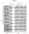
- Patent Document 1 for example, a fastener stringer 70 shown in Fig. 4 is described as one of Embodiments.
- the fastener stringer 70 shown in Fig. 4 has a fastener tape 71 woven with a weft yarn 81 and a plurality of warp yarns 82, and a plurality of coiled fastener elements 72 woven and fixed to the fastener tape 71.
- the fastener tape 71 has an element attaching portion 71a to which the fastener elements 72 are attached and a tape main body portion 71b attached to a fastener attached member.
- the weft yarn 81 and the warp yarn 82 forming the fastener tape 71 yarns having the same thickness are generally used.
- a plurality of warp yarns (warp yarns for fixing elements) 82 fixing the fastener elements 72, and a weft yarn 81 forming a woven texture by intersecting with these warp yarns 82 is disposed.
- a plurality of fastener elements 72 continuously molded in a coiled shape are inserted and fixed between the warp yarns 82 of the element attaching portion 71a at the time of weaving the element attaching portion 71a.
- Each of the fastener elements 72 has a coupling head portion disposed to be protruded from the fastener tape 71, an upper leg portion and a lower leg portion extending inward of the tape from the coupling head portion along a tape width direction, and a connecting portion connecting between an end part of the upper leg portion (or lower leg portion) and an end part of the lower leg portion (or upper leg portion) of another fastener element 72 adjacent in the tape length direction.
- the fastener stringer 70 shown in Fig. 4 particularly, it has a weaving structure that each time the weft yarn 81 is inserted, one fastener element 72 is inserted and fixed together with the weft yarn 81.
- Such a weaving structure is called as a weaving structure with one pitch per one-rotation, since the fastener element 72 is inserted and fixed in one pitch for each rotation of the weft yarn 81 forming the fastener tape 71.
- the tape main body portion 71b of the fastener tape 71 is formed using a weft yarn 81 continuously disposed from the element attaching portion 71a and a plurality of warp yarns 82. Further, a weft yarn returning end portion 74 is disposed at an outer side end part of the tape main body portion 71b opposite to the element attaching portion 71a. The weft yarn returning end portion 74 is formed such that a returning loop portion 73 formed of the weft yarn 81 is hooked to another returning loop portion 73 of the weft yarn 81 to be inserted at a next position and a plurality of the returning loop portions 73 are connected in a warp direction.
- two loops 75 are formed on the weft yarn 81 every time the weft yarn 81 is inserted, and these two loops 75 are respectively interlaced with two loops 75 formed on the weft yarn 81 at a next weft insertion position to form two loop rows 76 using a knitting needle appropriately disposed in a loom weaving the fastener tape 71. These two loop rows 76 are continuously formed along a warp direction, respectively.
- the fastener stringer 70 of Patent Document 1 as described above is woven with a weaving structure with one pitch per one-rotation, thereby the density of the weft yarn 81 is low.
- two loop rows 76 are formed in the tape main body portion 71b of the fastener tape 71, therefore, there is an advantage that positional displacement of the weave at the tape side edge portion (outer side tape end edge part) on the weft yarn returning end portion 74 side in the tape main body portion 71b is unlikely to occur.
- the positional displacement of the weave may be simply abbreviated as a misalignment.
- the fastener stringer 90 shown in Fig. 5 has a fastener tape 91 woven with a weft yarn 81 and a plurality of warp yarns 82, and a plurality of coiled fastener elements 92 woven and fixed to the fastener tape 91.
- the fastener tape 91 has an element attaching portion 91a and a tape main body portion 91b, and the plurality of coiled fastener elements 92 are fixed by weaving to the element attaching portion 91a.
- the fastener stringer 90 in Fig. 5 is formed with a weaving structure with one pitch per two-rotation in which one fastener element 92 is inserted and fixed each time the weft yarn 81 is inserted twice.
- the density of the weft yarn 81 can be made higher than in the case of the fastener stringer 70 shown in Fig. 4 , and the woven texture can be formed densely.
- a weft yarn returning end portion 94 is formed at an outer side tape end edge part of the fastener tape 91. Further, two loop rows 96 are continuously formed along a warp direction in the tape main body portion 91b of the fastener tape 91.
- Patent Document 2 a fastener stringer in which coiled fastener elements are woven and fixed to an element attaching portion of a fastener tape, and the fastener tape and the fastener elements are woven with a weaving structure with one pitch per one-rotation is described.
- a monofilament thicker than the other warp yarn for fixing elements is used as a part of a plurality of warp yarns for fixing elements forming the element attaching portion of the fastener tape.
- the warp yarn formed of the thick monofilament is used for at least one warp yarn for fixing elements disposed on a connecting portion side of the fastener element among the plurality of warp yarns for fixing elements which fixes the fastener elements.
- the force for tightening the upper leg portion and the lower leg portion of the fastener element is larger than the force for tightening the upper leg portion and the lower leg portion with the other warp yarns for fixing elements.
- the slide fastener can be smoothly opened and closed by the slider. Further, it is possible to slightly enlarge or reduce a distance between the coupling head portions of the fastener elements adjacent in the tape length direction, therefore, the coupling operation of the right and left fastener elements can be smoothly performed.
- the fastener tape 91 having a high density of weft yarn 81 is formed.
- the tape main body portion 91b of the fastener tape 91 can be formed with various woven textures, and the fastener tape 91 can have versatility.
- the fastener stringer 90 when forming the fastener stringer 90 with the weaving structure with one pitch per two-rotation, compared to the case of forming the fastener stringer 70 with the weaving structure with one pitch per one-rotation as shown in Fig. 4 , for example, the number of insertions (the number of weft insertions) of the weft yarn 81 in a weaving process of the fastener tape 91 is doubled. Therefore, the productivity of the fastener stringer 90 is reduced and the manufacturing cost is increased. Further, the increase in the density of the weft yarn 81 may interfere with the weight reduction of the fastener stringer 90, and it may also affect the flexibility of the fastener stringer 90.
- the fastener stringer formed with the weaving structure with one pitch per one-rotation since the woven texture of the fastener tape (particularly the woven texture of the tape main body portion) is coarser than that of the weaving structure with one pitch per two-rotation, there is a problem that misalignment of the fastener tape is likely to occur. That is, in a case that the weave of the tape main body portion in the fastener tape is coarse, and when the slide fastener is attached to the fastener attached member and used, the tape main body portion of the fastener tape is likely to be misaligned to a large extent due to a lateral pulling force generated on the fastener stringer at the time of opening or closing the slide fastener.
- the present invention has been made in view of the above conventional problems, and a specific object of the invention is to provide a woven fastener stringer which can be manufactured at a low cost by adopting the weaving structure with one pitch per one-rotation capable of ensuring high productivity and which can make the tape main body portion less likely to be misaligned, and further to provide the woven fastener stringer which is expected to reduce the weight and to improve the flexibility of the fastener stringer.
- a fastener stringer provided by the present invention has a fastener tape woven by a weft yarn and a plurality of warp yarns and a plurality of continuous fastener elements fixed by weaving to the fastener tape along a tape length direction at the same time of weaving the fastener tape, in which the fastener tape is provided with a tape main body portion and an element attaching portion which extends in a tape width direction from one side edge part of the tape main body portion and to which the fastener elements are fixed, and the fastener stringer having a weaving structure in which the weft yarn is inserted once for each pitch of the fastener elements characterized in that the weft yarn has a fineness larger than at least a part of the warp yarns disposed in the tape main body portion of the fastener tape.
- the warp yarn disposed in the tape main body portion has a first warp yarn having a predetermined fineness and a second warp yarn having a fineness larger than the first warp yarn, and the weft yarn has a fineness larger than the first warp yarn.
- the tape main body portion has a thick yarn-continuing area in which a plurality of the second warp yarns are disposed continuously along the tape width direction.
- the fastener tape has a weft yarn returning end portion which is disposed at the other side edge part of the tape main body portion and at which the weft yarn forms a loop and returns, the thick yarn-continuing area is disposed in the tape width direction from a position of the warp yarn adjacent to the weft yarn returning end portion, and a thin yarn-continuing area in which a plurality of the first warp yarns are continuously disposed is disposed between the thick yarn-continuing area and the element attaching portion.
- the weft yarn and the second warp yarn have a fineness twice as large as the fineness of the first warp yarn.
- the weft yarn and the second warp yarn have a configuration in which two yarns forming the first warp yarn are aligned.
- a fineness of the weft yarn is 500 dtex or larger and 1000 dtex or smaller
- a fineness of the first warp yarn is 166 dtex or larger and 500 dtex or smaller
- a fineness of the second warp yarn is 500 dtex or larger and 1000 dtex or smaller.
- the fastener stringer according to the present invention is a woven fastener stringer having a fastener tape provided with a woven texture and a plurality of continuous fastener elements fixed by weaving to the fastener tape along a tape length direction at the same time of weaving the fastener tape.
- the fastener tape of the present invention has a tape main body portion and an element attaching portion which are partitioned in a tape width direction, and the fastener elements are fixed to the element attaching portion of the fastener tape.
- the fastener stringer of the present invention has a weaving structure in which the weft yarn is inserted once for each pitch of continuously formed fastener elements, in other words, a weaving structure with one pitch per one-rotation in which one fastener element is inserted and fixed each time the weft yarn is inserted once. Therefore, in the fastener stringer of the present invention, as compared to the fastener stringer 90 of Fig. 5 formed with the conventional weaving structure with one pitch per two-rotation, for example, it is possible to manufacture with high productivity by reducing the number of insertion of the weft yarn, therefore, significant cost reduction can be achieved.
- the fastener stringer of the present invention at the same time as the fastener tape is formed with a weaving structure with one pitch per one-rotation, the thicker yarn than at least a part of warp yarns (specifically, a first warp yarn described later) disposed in the tape main body portion is used for the weft yarn of the fastener tape. Since the tape main body portion is formed using the weft yarn having such a large fineness, as compared with the fastener stringer 70 of Fig. 4 formed with the conventional weaving structure with one pitch per one-rotation, for example, the tape main body portion is formed to have higher density weft (in other words, the tape main body portion is formed with a dense structure).
- a plurality of first warp yarns having a predetermined fineness and a plurality of second warp yarns having a fineness larger than the first warp yarn are disposed in the tape main body portion of the fastener tape as the warp yarns disposed in a warp direction.
- the fineness of the weft yarn of the fastener tape is larger than that of the first warp yarn.
- the presence of the thick second warp yarn can further improve the tape strength and the abrasion resistance of the fastener tape, and at the same time, the presence of the thin second warp yarn can suppress the negative effect of using the thick second warp yarn.
- the tape main body portion is formed using only the thick second warp yarn, for example, large irregularities is likely to be formed on a tape top surface or a tape back surface of the tape main body portion. Therefore, it is considered that the appearance (appearance quality) of the fastener tape is lowered, or the touch of the fastener tape becomes worse. Moreover, it is also considered that the weight increase of the fastener tape or less flexibility of the fastener tape are caused.
- the tape main body portion of the fastener tape is formed using not only the second warp yarn but also the first warp yarn having a smaller fineness than the second warp yarn, lowering of the appearance (appearance quality) and of the touch as described above can be suppressed and the weight reduction and cost reduction of the fastener tape can be achieved.
- the first warp yarn is disposed in the tape main body portion, the fastener tape can be provided with appropriate flexibility.
- the two types of the warp yarns which are the first warp yarn having a smaller fineness than the weft yarn and the second warp yarn having a larger fineness than the first warp yarn are disposed in the tape main body portion of the fastener tape, so that advantages of using the first warp yarn such as good appearance and good touch and advantages of using the second warp yarn such as high tape strength and abrasion resistance can be provided in combination in a well-balanced manner.
- the tape main body portion of the fastener tape has the thick yarn-continuing area in which the plurality of second warp yarns are continuously disposed in the tape width direction.
- the fastener tape of the present invention has the weft yarn returning end portion which is disposed at the other side edge part of the tape main body portion and at which the weft yarn forms a loop and returns.
- the above-described thick yarn-continuing area in which the plurality of second warp yarns are continuously disposed is disposed so as to extend in the tape width direction from a position of the warp yarn adjacent to the weft yarn returning end portion of the fastener tape.
- the thin yarn-continuing area in which a plurality of thin first warp yarns are continuously disposed is disposed between the thick yarn-continuing area and the element attaching portion.
- the position of a sewn portion at which the fastener tape and the fastener attached member are sewn together can be set to the position within the thick yarn-continuing area or in the vicinity of the thick yarn-continuing area of the tape main body portion.
- the thin yarn-continuing area in which the plurality of first warp yarn are continuously disposed in the tape main body portion of the fastener tape good appearance and good touch of the fastener tape by use of the thin first warp yarn are obtained stably, and appropriate flexibility of the fastener tape can be provided.
- the weft yarn and the second warp yarn have a fineness twice as large as the fineness of the first warp yarn. This ensures good appearance and good touch of the fastener tape, and effectively suppresses the occurrence of misalignment in the woven texture to stably ensure the appropriate tape strength and abrasion resistance of the fastener tape that can endure the use of the slide fastener.
- the above-described weft yarn and the second warp yarn have a configuration in which two yarns forming the first warp yarn are aligned.
- the fineness of the weft yarn and the second warp yarn can be certainly made larger than the fineness of the first warp yarn.
- the fineness of the weft yarn is 500 dtex or larger and 1000 dtex or smaller.
- the fineness of the first warp yarn is 166 dtex or larger and 500 dtex or smaller.
- the fineness of the second warp yarn is 500 dtex or larger and 1000 dtex or smaller.
- a plurality of fastener elements fixed by weaving to the fastener tape are formed continuously by molding a monofilament in a coiled shape.
- the present invention is not limited thereto, however, a plurality of fastener elements may be formed continuously by molding a monofilament in a zig-zag shape.
- a material of the weft yarn and the respective warp yarns configuring the fastener tape is not particularly limited, and the same yarn as that generally used in the conventional fastener stringer can be adopted.
- Fig. 1 is a plan view schematically showing a slide fastener having a fastener stringer according to the present Embodiment.
- Fig. 2 is a schematic view schematically explaining the woven texture of the fastener stringer.
- Fig. 3 is a cross-sectional view schematically showing a state in which the slide fastener is attached to a fastener attached member of a product.
- the woven structure (woven texture) of the fastener stringer is roughly shown. Actually, however, yarns having a predetermined thickness are used for the weft yarn and each warp yarn forming the fastener tape, and the woven texture of the fastener tape is formed densely in consideration of the function as a fastener stringer.
- a front and rear direction means a tape length direction of the fastener tape, and means the same linear direction as the sliding direction in which the slider slides.
- a right and left direction means a tape width direction of the fastener tape, and is a direction parallel to a tape surface of the fastener tape and perpendicular to the tape length direction.
- An upper and lower direction means a tape top and back direction perpendicular to the tape top surface and the tape back surface of the fastener tape.
- a direction perpendicular to the front and rear direction and the right and left direction and on a side the tab of the slider is disposed with respect to the fastener tape is an upper side, and a direction on the opposite side is a lower side.
- a warp direction warp yarn direction
- a length direction of the warp yarn is a length direction of the warp yarn, and the same direction as the tape length direction of the fastener tape.
- a slide fastener 1 has a right and left pair of fastener stringers 10 in which element rows 12 are respectively formed by weaving a plurality of fastener elements 11 into facing tape side edge parts (element attaching portions, described later) 21 of the right and left fastener tapes 20, a slider 40 attached along the right and left element rows 12 in a slidable manner, and a first stop 51 (also referred to as an upper stop) disposed adjacent to front end parts of the right and left element rows 12, and a second stop 52 (also referred to as a lower stop) adjacent to rear end parts of the right and left element rows 12 and connecting between the right and left fastener stringers 10.
- a first stop 51 also referred to as an upper stop
- a second stop 52 also referred to as a lower stop
- the slide fastener 1 of the present Embodiment is characterized mainly in the fastener tape 20 of the fastener stringer 10, and the slider 40, the first stop 51, and the second stop 52 of the present Embodiment are formed in substantially the same manner as the slider, first stop, and second stop generally used in the conventional slide fastener.
- the slider 40 of the present Embodiment is, for example, provided with a slider body 41 and a tab 49 rotatably held by the slider body 41.
- the slider body 41 has an upper blade 42 and a lower blade 43 disposed parallel to each other, a connecting column (not shown) connecting a front end part of the upper blade 42 and a front end part of the lower blade 43, right and left upper flange portions 44 extending downward from right and left side edge parts of the upper blade 42, and a tab attaching portion 45 standing on an upper surface of the upper blade 42.
- the right and left upper flange portions 44 of the slider body 41 are contacted with the fastener elements 11 attached to the right and left fastener stringers 10, thereby, the position of the fastener elements 11 in the tape width direction in the slider body 41 is controlled.
- a front end part of the slider body 41 is provided with shoulder mouths disposed on both right and left sides of the connecting column, and a rear end part of the slider body 41 is provided with a rear mouth. Further, a substantially Y-shaped element guide pass is formed to connect the right and left shoulder mouths and the rear mouth so as to be surrounded by the upper blade 42, the lower blade 43, and the right and left upper flange portions 44. Furthermore, a tape insertion gap 46 for inserting the fastener tape 20 is formed between the right and left upper flange portions 44 and the lower blade 43 in the slider body 41.
- the first stop 51 and the second stop 52 are provided to be continuous with the front and rear of the element rows 12 respectively in the right and left fastener tapes 20. Since the first stop 51 and the second stop 52 are disposed, the slider 40 can be prevented from falling off from the right and left element rows 12.
- the structures, etc. of the slider 40, the first stop 51, and the second stop 52 can be arbitrarily changed, if necessary.
- a separable rear end stop having an insert pin formed on one fastener tape 20, a box pin formed on the other fastener tape 20, and a box body integrally formed at a rear end part of the box pin and having an insertion concave portion into which the insert pin can be inserted may be provided.
- the right and left fastener stringers 10 in the present Embodiment respectively have a fastener tape 20 woven using a weft yarn 31 and a plurality of warp yarns 32 and fastener elements 11 formed continuously in a coiled shape and woven into the fastener tape 20 at the same time of weaving the fastener tape 20.
- the fastener stringer 10 of the present Embodiment is formed with so-called a weaving structure with one pitch per one-rotation in which one fastener element 11 is inserted and fixed together with the weft yarn 31 each time the weft yarn 31 is inserted once.
- each of the right and left fastener tapes 20 has an element attaching portion 21 to which the fastener elements 11 are fixed by weaving, and a tape main body portion 22 extending in the tape width direction from the element attaching portion 21. That is, the tape main body portion 22 and the element attaching portion 21 are disposed to be divided in the tape width direction by a predetermined boundary part (not shown) along the tape length direction of the fastener tape 20.
- the tape main body portion 22 of the fastener tape 20 is a tape part which is overlapped and sewn to the fastener attached member 60 (for example, the fabric of the clothing) of the product when the slide fastener 1 is attached to the product such as the clothing.
- the tape main body portion 22 is, in a plan view of the fastener stringer 10 as viewed from above (see Fig. 2 , for example), regarding the tape width direction, an area from a position of an element side end edge on a tape inner side in the fastener element 11 to a tape end edge (tape outer end edge) disposed on the opposite side to the tape end edge (tape inner end edge) on the side to which the fastener element 11 is attached.
- the element attaching portion 21 of the fastener tape 20 is a tape side edge portion 21 extending in the tape width direction from one side edge (tape inner-side side edge) of the tape main body portion 22 toward the fastener stringer 10 on the coupling counterpart side.
- the element attaching portion (tape side edge portion) 21 is, regarding the tape width direction, an area from the position of the element side end edge on the tape inner side in the fastener element 11 to the above-mentioned tape inner end edge of the fastener tape 20.
- the plurality of fastener elements 11 in the present Embodiment are formed to connect continuously in the tape length direction by molding a synthetic resin monofilament into a coiled shape.
- Each fastener element 11 has a coupling head portion 11a, an upper leg portion 11b and a lower leg portion 11c extending in the tape width direction from the coupling head portion 11a, and a connecting portion 11d extending from the upper leg portion 11b or the lower leg portion 11c to be connected to the fastener element 11 adjacent in the tape length direction.
- the coupling head portion 11a of the fastener element 11 is formed in the upper and lower direction so as to connect the upper leg portion 11b and the lower leg portion 11c, and is provided with a bulged portion bulging in the front and rear direction at an intermediate part in the upper and lower direction.
- the upper leg portion 11b extends toward the tape width direction from an upper end part of the coupling head portion 11a.
- the lower leg portion 11c extends toward the fastener width direction substantially in parallel with the upper leg portion 11b from a lower end part of the coupling head portion 11a.
- the connecting portion 11d connects the upper leg portion 11b of each fastener element 11 and the lower leg portion 11c of the fastener element 11 adjacent to one of the fastener elements 11 in the front and rear direction (in other words, connects the lower leg portion 11c of each fastener element 11 and the upper leg portion 11b of the fastener element 11 adjacent to the other of the fastener elements 11 in the front and rear direction).
- Each fastener element 11 is fixed to the element attaching portion 21 such that the coupling head portion 11a is protruded to an outside of the tape width direction from the tape side edge of the fastener tape 20 on the element attaching portion 21 side and the upper leg portion 11b and the lower leg portion 11c are woven into the element attaching portion 21 at the time of weaving the fastener tape 20.
- the woven texture of the fastener tape 20 is, as shown in Fig. 2 , for example, formed by reciprocating a carrier bar (not shown) with respect to a plurality of warp yarns 32 held along the warp direction and inserting the weft 31 into openings between the warp yarns 32.
- polyester fibers are used for the weft yarn 31 and the plurality of warp yarns 32 forming the fastener tape 20.
- the weft yarn 31 of the fastener tape 20 is disposed to cross the warp yarns 32 in a form of a double yarn in which two weft yarns 31 are aligned.
- the weft yarn 31 of the present Embodiment is formed of a thick yarn having larger fineness than a first warp yarn 33, described later, disposed in the tape main body portion 22.
- the tape main body portion 22 of the fastener tape 20 is formed by weaving the weft yarn 31 and the plurality of warp yarns 32 disposed in the form of a double yarn as described above in a plain woven texture.
- a weft yarn returning end portion 23 is disposed at an end part of the tape main body portion 22 opposite to the side on which the element attaching portion 21 is formed.
- the weft yarn returning end portion 23 is formed by connecting a plurality of returning loop portions in the warp direction by hooking the returning loop portion formed of the weft yarn 31 to the returning loop portion of the weft yarn 31 to be inserted at the next position.
- first warp yarn 33 and second warp yarn 34 two types of warp yarns 32 (first warp yarn 33 and second warp yarn 34) having different fineness are used as the warp yarns 32 forming the tape main body portion 22.
- the same yarn having the same fineness is commonly used for the warp yarn forming the tape main body portion.
- the warp yarns 32 disposed in the tape main body portion 22 have a plurality of first warp yarns 33 having a predetermined fineness, described later, and a plurality of second warp yarns 34 having a larger fineness than the first warp yarn 33.
- the plurality of second warp yarns 34 having a larger fineness are continuously disposed from the position of the warp yarn 32 adjacent to the weft yarn returning end portion 23 toward a direction to approach the element attaching portion 21 in the tape width direction.
- a thick yarn-continuing area 24 formed of the plurality of second warp yarns 34 is formed in the tape main body portion 22.
- the thick yarn-continuing area 24 is formed to have a predetermined size (dimension) in the tape width direction.
- the thick yarn-continuing area 24 of the tape main body portion 22 is formed such that a dimension in the tape width direction of the thick yarn-continuing area 24 is 1/4 or larger, and particularly 1/3 or larger with respect to the dimension of the entire tape main body portion 22 in the tape width direction. Further, when defined in a specific size, it is preferable that the thick yarn-continuing area 24 is, for example, formed from the position of the warp yarn 32 adjacent to the weft yarn returning end portion 23 to the position that a dimension of the fastener tape 20 on the weft yarn returning end portion 23 side in the tape width direction from the tape side edge is 3.5 mm or larger, and particularly 5 mm or larger.
- the thick yarn-continuing area 24 is formed continuously in the region of the tape width direction as described above, the density of the weft yarn 31 and the warp yarn 32 in the region is increased, and the tape strength and the abrasion resistance of the fastener tape 20 can be improved effectively.
- the high density of the weft yarn 31 and the warp yarn 32 means that the weight of the weft yarn 31 and the warp yarn 32 per unit area is large (heavy).
- the thick yarn-continuing area 24 of the tape main body portion 22 is provided with an appropriate dimension in the tape width direction, when the fastener stringer 10 is sewn and fixed to a fastener attached member 60 of the product, described later, the position of a sewn portion (sewn line) 61 for sewing the fastener tape 20 and the fastener attached member 60 can be easily set within the thick yarn-continuing area 24 with high yarn density in the tape main body portion 22 or the area close to the thick yarn-continuing area 24.
- the sewn portion 61 of the fastener attached member 60 is formed at the above-described position of the tape main body portion 22 (in particular, the position within the thick yarn-continuing area 24), when the slide fastener 1 receives a lateral pulling force to be pulled toward the outer side in the tape width direction via the fastener attached member 60, for example, the position of the weave in the thick yarn-continuing area 24 can be less likely to be misaligned. As a result, tape strength and abrasion resistance of the fastener tape 20 can be maintained properly.
- the position and size of the thick yarn-continuing area 24 are not particularly limited, and can be changed arbitrarily depending on the dimension in the tape width direction of the fastener tape 20, and the size of the fastener element 11, the use of the slide fastener 1, etc.
- a thin yarn-continuing area 25 in which a plurality of first warp yarns 33 thinner than the second warp yarn 34 are continuously disposed is formed between the above-described thick yarn-continuing area 24 and the element attaching portion 21.
- the tape main body portion 22 of the fastener tape 20 has not only the thick yarn-continuing area 24 formed of the second warp yarn 34 as described above but also the thin yarn-continuing area 25 of the first warp yarn 33, thereby, the tape main body portion 22 can be less likely to be misaligned as mentioned above, and at the same time, good appearance and good touch of the fastener tape 20 can be obtained.
- the manufacturing cost can be reduced and the weight of the fastener stringer 10 can be reduced as compared with the case that the tape main body portion 22 is formed only with the thick yarn-continuing area 24, for example.
- the dimension in the tape width direction of the thin yarn-continuing area 25 is not particularly limited. Although at least one first warp yarn 33 is disposed in the tape main body portion 22, two or more first warp yarns 33 are preferably disposed continuously in the tape width direction. As a further preferable configuration, the thin yarn-continuing area 25 of the tape main body portion 22 is, as shown in Fig. 3 , for example, provided in such a size that a running region in which the upper flange portion 44 of the slider body 41 runs is disposed in the thin yarn-continuing area 25.
- the fastener tape 20 can be stably inserted into the tape insertion gap 46 without securing a size of the tape insertion gap 46 in the slider body 41 to a large extent.
- the dimension (height dimension) in the upper and lower direction of the upper flange portion 44 is appropriately secured.
- a step in the height direction can be stably formed between a position of the upper surface of the tape main body portion 22 in the fastener tape 20 and a position of an upper end of the connecting portion 11d in the fastener element 11.
- the fastener element 11 can be contacted with the upper flange portion 44, and the position of the element row 12 in the slider body 41 can be stably controlled. Therefore, the fastener element 11 can be stably held in the slider body 41 by preventing the fastener element 11 from popping out in the tape width direction (right and left direction) from inside the slider body 41 via the tape insertion gap 46. Thereby, the right and left element rows 12 can be smoothly coupled or disengaged by the sliding operation of the slider 40.
- the thin yarn-continuing area 25 of the tape main body portion 22 higher flexibility can be easily obtained as compared to the thick yarn-continuing area 24. Since the running region of the upper flange portion 44 is disposed in such a thin yarn-continuing area 25, when the slider 40 is slid in the closing direction (forward) of the slide fastener 1, for example, the right and left fastener elements 11 can be easily coupled. Therefore, the sliding property of the slider 40 can be expected to be improved.
- the thin yarn-continuing area 25 of the tape main body portion 22 is formed such that three or more, preferably five or more first warp yarns 33 are continuously disposed from a position of the warp yarn 32 adjacent to the element attaching portion 21 toward the weft yarn returning end portion 23.
- the yarn having the larger fineness than the first warp yarn 33 disposed in the tape main body portion 22 is used for the weft yarn 31 and the second warp yarn 34 disposed in the tape main body portion 22 as described above.
- yarns having the same fineness are used for the weft yarn 31 and the second warp yarn 34.
- a plain woven texture can be firmly and stably formed by the weft yarn 31 and the second warp yarn 34.
- the manufacturing cost can be reduced.
- the fineness of the weft yarn 31 and the fineness of the second warp yarn 34 are set to be twice as large as the fineness of the first warp yarn 33.
- the fineness of the first warp yarn 33 is 330 dtex (300 denier)
- the fineness of the weft yarn 31 and the fineness of the second warp yarn 34 are set at 660 dtex (600 denier).
- tape strength of the fastener tape 20 can be improved, and appearance of the woven fastener tape can be improved.
- the yarn used for the weft yarn 31 and the yarn used for the second warp yarn 34 are formed in a shape that two yarns (multifilament yarns) used for the first warp yarn 33 are aligned.
- the fineness of the weft yarn 31 and the second warp yarn 34 and the fineness of the first warp yarn 33 can be easily and reliably made different, and the fineness of each yarn can also be adjusted easily.
- the yarns of the weft yarn 31 and the yarns of the second warp yarn 34 can be respectively formed by using the yarns forming the first warp yarn 33, it is possible to further reduce the manufacturing cost.
- the weft yarn 31 and the second warp yarn 34 are respectively represented by a single yarn in order to make the arrangement of each yarn easy to be understood.
- each of the weft yarn 31 and the second warp yarn 34 of the present invention may be formed in a form of one multifilament yarn (twisted yarn).
- specific fineness of the weft yarn 31, the first warp yarn 33, and the second warp yarn 34 are set as follows according to, for example, the size of the fastener tape 20.
- the fineness of the weft yarn 31 is set at 500 dtex (450 denier) or larger and 1000 dtex (900 denier) or smaller, and preferably 660 dtex (600 denier).
- the fineness of the first warp yarn 33 is set at 166 dtex (150 denier) or larger and 500 dtex (450 denier) or smaller, and preferably 330 dtex (300 denier).
- the fineness of the second warp yarn 34 is set at 500 dtex (450 denier) or larger and 1000 dtex (900 denier) or smaller, and preferably 660 dtex (600 denier).
- the element attaching portion 21 of the fastener tape 20 is formed of the weft yarn 31 continuously inserted from the tape main body portion 22 and disposed along the lower leg portion 11c of each fastener element 11 and the plurality of warp yarns 32.
- the warp yarn 32 disposed in the element attaching portion 21 has two head portion-side lower warp yarn for fixing 35 disposed closer to the coupling head portion 11a of the fastener element 11 and running on a lower surface side of the lower leg portion 11c of each fastener element 11 in the warp direction, six warp yarns for tightening 36 running in the warp direction so as to cross over the lower surface side of the lower leg portion 11c and the upper surface side of the upper leg portion 11b of the fastener element 11, and two connecting portion-side lower warp yarns for fixing 37 disposed closer to the connecting portion 11d of the fastener element 11 and running on the lower surface side of the lower leg portion 11c of each fastener element 11 in the warp direction.
- each warp yarn 32 (coupling head portion-side lower warp yarn for fixing 35, warp yarn for tightening 36, and connecting portion-side lower warp yarn for fixing 37) disposed in the element attaching portion 21.
- the weft yarn 31 disposed in the element attaching portion 21 is inserted in a direction perpendicular to the warp direction so as to run in a direction as described below (or run in the opposite direction thereof). That is, at a position where the upper leg portion 11b and the lower leg portion 11c in the warp direction are disposed, the weft yarn 31 runs in a weft direction from the tape main body portion 22 on the lower surface side of the lower leg portion 11c along the lower leg portion 11c, interlaces with the two head portion-side lower warp yarns for fixing 35 disposed on the coupling head portion 11a side to be returned so as to turn around the circumference of the head portion-side lower warp yarn for fixing 35 disposed the closest to the coupling head portion 11a. Further, the returned weft yarn 31 at the head portion-side lower warp yarn for fixing 35 runs on the lower surface side of the lower leg portion 11c in the weft direction and is returned to the tape main body portion 22.
- the two head portion-side lower warp yarns for fixing 35 in the element attaching portion 21 are disposed adjacent to each other in an area on the coupling head portion 11a side of the six warp yarns for tightening 36, and the weft yarn 31 is returned (reversed) by the two head portion-side lower warp yarns for fixing 35 at a position on the coupling head portion 11a side.
- the six warp yarns for tightening 36 in the element attaching portion 21 are disposed in the warp direction while being alternately interlaced in a constant cycle respectively so as to interpose the upper leg portion 11b of the fastener element 11, the lower leg portion 11c of the fastener element 11 and the weft yarn 31 running along the lower leg portion 11c.
- the two adjacent warp yarns for tightening 36 having symmetrical running direction in the tape top and back direction as one set
- three sets of warp yarns for tightening 36 are disposed at a predetermined interval in the tape width direction.
- the two connecting portion-side warp yarns for fixing 37 in the element attaching portion 21 are disposed adjacent to each other in an area on the connecting portion 11d side of the six warp yarns for tightening 36.
- These two connecting portion-side lower yarns for fixing 37 are alternately interlaced with the weft yarns 31 to form a weave.
- the woven texture of the element attaching portion 21 in the fastener tape 20 is not particularly limited, and, the number of warp yarns for tightening 36 disposed in the element attaching portion 21, for example, can be arbitrarily changed.
- the element attaching portion 21 of the fastener tape 20 can also be formed with a woven texture other than the Embodiment described above.
- the fastener stringer 10 according to the present Embodiment as described above can be manufactured using a loom generally used for manufacturing the conventional ordinary woven fastener stringer, and can be easily manufactured as compared with manufacturing the fastener stringer 70 in which two loop rows 76 are formed in the tape main body portion 71b as shown in Fig. 4 , for example.
- the fastener stringer 10 of the present Embodiment is manufactured with a weaving structure with one pitch per one-rotation as described above. Therefore, the fastener stringer 10 of the present Embodiment can significantly improve the productivity and can reduce the manufacturing cost of the fastener stringer 10 as compared to the fastener stringer 90 adopting the weaving structure with one pitch per two-rotation as shown in Fig. 5 , for example.
- the density of the weft yarn 31 and the warp yarn 32 in the tape main body portion (in particular, the density of the weft yarn 31 and the warp yarn 32 in the thick yarn-continuing area 24) can be significantly increased, as compared to the conventional fastener stringer 70 shown in Fig. 4 , for example. As a result, positional deviation of weave can be less likely to occur on the fastener tape 20, as described later.
- the slide fastener 1 shown in Fig. 1 can be manufactured by using the two fastener stringers 10 of the present Embodiment as described above in a pair.
- a fastener attached member 60 of the product for example, fabric of the clothing
- the tape main body portion 22 of the fastener tape 20 are overlapped, and the overlapped part is sewing-processed using a sewing machine.
- the fastener tape 20 and the fastener attached member 60 of the product are sewn together with the sewn portion (sewn line) 61 formed by the sewing machine, so that the slide fastener 1 can be attached to the product stably.
- the thick yarn-continuing area 24 in the tape main body portion 22 of the fastener tape 20 is overlapped with the fastener attached member 60 of the product, and the thick yarn-continuing area 24 is sewn to the fastener attached member 60 with the sewn portion 61.
- the fastener tape 20 is formed such that the yarn density of the tape main body portion 22 (particularly the thick yarn-continuing area 24) is increased to prevent occurrence of misalignment.
- the tape main body portion 22 (particularly the thick yarn-continuing area 24) of the fastener tape 20 is sewn to the fastener attached member 60 of the product.
- the tape main body portion 22 of the fastener tape 20 has the thick yarn-continuing area 24 disposed adjacent to the weft yarn returning end portion 23 and the thin yarn-continuing area 25 disposed adjacent to the element attaching portion 21.
- a thin yarn-continuing area 25 formed of the first warp yarn 33 may be further provided between the weft yarn returning end portion 23 and the thick yarn-continuing area 24.
- a thick yarn-continuing area 24 formed of the second warp yarn 34 may also be further provided between the thin yarn-continuing area 25 and the element attaching portion 21.
- the weft yarn 31 of the fastener tape 20 is formed thicker than the first warp yarn 33 of the tape main body portion 22, it is possible to weave a fastener tape 20 having a tape main body portion 22 in which the first warp yarn 33 and the second warp yarn 34 thicker than the first warp yarn 33 are disposed alternately in the tape width direction and the thick yarn-continuing area 24 and the thin yarn-continuing area 25 are not provided. Further, it is also possible to weave a fastener tape 20 using only the first warp yarn 33 without using the second warp yarn 34 to the tape main body portion 22.
- Embodiments 1 and 2 will be more specifically described by showing Embodiments 1 and 2 and a Comparative Example.
- a yarn having a fineness of 330 dtex (300 denier) was used as the first warp yarn 33 of the tape main body portion 22 and each warp yarn 32 disposed in the element attaching portion 21, and a yarn having a fineness of 660 dtex (600 denier) was used as the weft yarn 31 and the second warp yarn 34 of the tape main body portion 22 to manufacture a fastener stringer 10 according to the above-described Embodiment.
- the fastener stringer 10 of Embodiment 1 is formed with the weaving structure with one pitch per one-rotation.
- the weft 31 and the second warp yarn 34 have a configuration in which two yarns used for the first warp yarn 33 are aligned.
- a thick yarn-continuing area 24 in which the second warp yarns 34 are continuously disposed in the tape width direction is formed.
- the thick yarn-continuing area 24 is, in the tape width direction of the tape main body portion 22, formed from a position of the warp yarn 32 adjacent to the weft yarn returning end portion 23 to a position of the warp yarn 32 separated by 4.5 mm in the tape width direction based on a position of the connecting portion 11d of the fastener element 11 (specifically, an end edge position of the connecting portion 11d on the tape main body portion 22 side).
- the manufactured fastener stringers 10 of Embodiment 1 were used in a set of two to manufacture a slide fastener 1 shown in Fig. 1 , and further, the right and left fastener tapes 20 in the obtained slide fastener 1 were sewn to the fastener attached member 60 of the product using a sewing machine.
- the position of the sewn portion 61 formed by the sewing machine was set at the position 5 mm away from the connecting portion 11d of the fastener element 11 in the tape width direction. Therefore, in Embodiment 1, the thick yarn-continuing area 24 in the tape main body portion 22 of the fastener tape 20 and the fastener attached member 60 of the product are sewn together with the sewn portion 61.
- a lateral pulling force was applied to the right and left fastener stringers 10 of the slide fastener 1 by pulling the right and left fastener attached members 60 of the product toward an outside in the right and left direction with a predetermined load. Furthermore, the state that the lateral pulling force was applied to the fastener stringers 10 was maintained for a predetermined time.
- the slide fastener 1 is removed from the fastener attached members 60 of the product while removing the lateral pulling force. Thereafter, the position of the weave at the point where the sewn portion 61 of the fastener tape 20 is formed was identified, and the length (i.e., the size of the misalignment) at which the position of the weave is shifted from the normal position (the position of the weave before the lateral pulling force was applied) was measured. The size of such a misalignment was measured at ten different positions on the straight line on which the sewn portion 61 was formed in the fastener tape 20 to determine the average value. As a result, the average value of the size of the misalignment in Embodiment 1 was 1.88 mm.
- the fineness of the thickest warp yarn disposed in the tape main body portion of the fastener tape is 330 dtex (300 denier).
- the fastener stringer of Embodiment 2 is formed in the same manner as in the case of the above-mentioned Embodiment 1 except having changed the fineness of the warp yarn disposed in the tape main body portion.
- the manufactured fastener stringer of Embodiment 2 was used to manufacture a slide fastener in the same manner as in Embodiment 1, and further, the slide fastener was sewn to the fastener attached member 60 of the product using a sewing machine. Thereafter, the size of misalignment was measured under the same conditions as in Embodiment 1 to determine the average value. As a result, the average value of the size of the misalignment in Embodiment 2 was 3.42 mm.
- the fineness of the thickest warp yarn disposed in the tape main body portion of the fastener tape is 330 dtex (300 denier).
- the fastener stringer of Comparative Example is formed in the same manner as in the case of the above-mentioned Embodiment 1 except having changed the fineness of the warp yarn disposed in the tape main body portion and the fineness of the weft yarn.
- the manufactured fastener stringer of Comparative Example was used to manufacture a slide fastener in the same manner as in Embodiment 1, and further, the slide fastener was sewn to the fastener attached member 60 of the product using a sewing machine. Thereafter, the size of misalignment was measured under the same conditions as in Embodiment 1 to determine the average value. As a result, the average value of the size of the misalignment in Comparative Example was 4.38 mm.
- the misalignment was able to be suppressed to a small extent by making the fineness of the weft yarn larger than the case of the fastener stringer of Comparative Example. As a result, it was confirmed that the misalignment of the fastener tape can be suppressed to a small extent by weaving the fastener tape using the thick weft yarn of 660 dtex as compared to the case that the thin weft yarn of 330 dtex is used.
- a plurality of warp yarns 32 (second warp yarns 34) having a larger fineness than those of the fastener stringer of Embodiment 2 are continuously disposed in the tape main body portion 22 of the fastener tape 20, thereby, misalignment was able to be further suppressed to a small extent. Accordingly, it was confirmed that the thick weft yarn 31 of 660 dtex is disposed in the fastener tape 20, and the thick second warp yarns 34 of 660 dtex are disposed in the tape main body portion 22 of the fastener tape 20, thereby, misalignment of the fastener tape 20 can be further suppressed effectively.
Landscapes
- Engineering & Computer Science (AREA)
- Textile Engineering (AREA)
- Slide Fasteners (AREA)
- Woven Fabrics (AREA)
Abstract
Description
- The present invention relates to a fastener stringer in which fastener elements are fixed by weaving to a fastener tape at the same time of weaving of the fastener tape.
- As one of the fastener stringers, a fastener stringer in which a plurality of coiled fastener elements molded continuously from a synthetic resin monofilament are woven and fixed along one side edge part of a fastener tape at the same time of weaving the fastener tape is known. This kind of fastener stringer is commonly called as a woven fastener stringer.
- In a case of such a woven fastener stringer, the fastener tape is woven using a weft yarn and a plurality of warp yarns. The fastener tape has a tape main body portion attached to a fastener attached member in products such as clothing and an element attaching portion which extends in a tape width direction from one side edge part of the tape main body portion and to which the fastener elements are fixed.
- Such a woven fastener stringer is described in, for example, Japanese Patent Application Publication Nos.
2000-303298 A 2002-85113 A Patent Document 1, for example, afastener stringer 70 shown inFig. 4 is described as one of Embodiments. - The
fastener stringer 70 shown inFig. 4 has afastener tape 71 woven with aweft yarn 81 and a plurality ofwarp yarns 82, and a plurality of coiledfastener elements 72 woven and fixed to thefastener tape 71. In this case, thefastener tape 71 has anelement attaching portion 71a to which thefastener elements 72 are attached and a tapemain body portion 71b attached to a fastener attached member. Further, as theweft yarn 81 and thewarp yarn 82 forming thefastener tape 71, yarns having the same thickness are generally used. - In the
element attaching portion 71a of thefastener tape 71 shown inFig. 4 , a plurality of warp yarns (warp yarns for fixing elements) 82 fixing thefastener elements 72, and aweft yarn 81 forming a woven texture by intersecting with thesewarp yarns 82 is disposed. In addition, in theelement attaching portion 71a, a plurality offastener elements 72 continuously molded in a coiled shape are inserted and fixed between thewarp yarns 82 of theelement attaching portion 71a at the time of weaving theelement attaching portion 71a. - Each of the
fastener elements 72 has a coupling head portion disposed to be protruded from thefastener tape 71, an upper leg portion and a lower leg portion extending inward of the tape from the coupling head portion along a tape width direction, and a connecting portion connecting between an end part of the upper leg portion (or lower leg portion) and an end part of the lower leg portion (or upper leg portion) of anotherfastener element 72 adjacent in the tape length direction. - In a case of the
fastener stringer 70 shown inFig. 4 , particularly, it has a weaving structure that each time theweft yarn 81 is inserted, onefastener element 72 is inserted and fixed together with theweft yarn 81. Such a weaving structure is called as a weaving structure with one pitch per one-rotation, since thefastener element 72 is inserted and fixed in one pitch for each rotation of theweft yarn 81 forming thefastener tape 71. - The tape
main body portion 71b of thefastener tape 71 is formed using aweft yarn 81 continuously disposed from theelement attaching portion 71a and a plurality ofwarp yarns 82. Further, a weft yarn returningend portion 74 is disposed at an outer side end part of the tapemain body portion 71b opposite to theelement attaching portion 71a. The weft yarn returningend portion 74 is formed such that a returningloop portion 73 formed of theweft yarn 81 is hooked to another returningloop portion 73 of theweft yarn 81 to be inserted at a next position and a plurality of the returningloop portions 73 are connected in a warp direction. - Furthermore, in the fastener stringer 70 of
Fig. 4 , twoloops 75 are formed on theweft yarn 81 every time theweft yarn 81 is inserted, and these twoloops 75 are respectively interlaced with twoloops 75 formed on theweft yarn 81 at a next weft insertion position to form twoloop rows 76 using a knitting needle appropriately disposed in a loom weaving thefastener tape 71. These twoloop rows 76 are continuously formed along a warp direction, respectively. - The fastener stringer 70 of
Patent Document 1 as described above is woven with a weaving structure with one pitch per one-rotation, thereby the density of theweft yarn 81 is low. However, twoloop rows 76 are formed in the tapemain body portion 71b of thefastener tape 71, therefore, there is an advantage that positional displacement of the weave at the tape side edge portion (outer side tape end edge part) on the weft yarn returningend portion 74 side in the tapemain body portion 71b is unlikely to occur. In the following description, the positional displacement of the weave may be simply abbreviated as a misalignment. - Further, a fastener stringer 90 as shown in
Fig. 5 is described inPatent Document 1 as another Embodiment. - The
fastener stringer 90 shown inFig. 5 has afastener tape 91 woven with aweft yarn 81 and a plurality ofwarp yarns 82, and a plurality of coiledfastener elements 92 woven and fixed to thefastener tape 91. Thefastener tape 91 has anelement attaching portion 91a and a tapemain body portion 91b, and the plurality of coiledfastener elements 92 are fixed by weaving to theelement attaching portion 91a. - Further, the fastener stringer 90 in
Fig. 5 is formed with a weaving structure with one pitch per two-rotation in which onefastener element 92 is inserted and fixed each time theweft yarn 81 is inserted twice. By thus increasing the number of insertions of theweft yarn 81 with respect to thefastener element 92, the density of theweft yarn 81 can be made higher than in the case of thefastener stringer 70 shown inFig. 4 , and the woven texture can be formed densely. - Also in the fastener stringer 90 of
Fig. 5 , a weft yarn returningend portion 94 is formed at an outer side tape end edge part of thefastener tape 91. Further, twoloop rows 96 are continuously formed along a warp direction in the tapemain body portion 91b of thefastener tape 91. - In such a
fastener stringer 90 shown inFig. 5 , the twoloop rows 96 are formed in the tapemain body portion 91b, and the density of theweft yarn 81 is increased due to a weaving structure with one pitch per two-rotation. Therefore, in the outer side tape end edge part of the tapemain body portion 91b shown inFig. 5 , misalignment can be to occur yet than in the case of thefastener stringer 70 shown inFig. 4 . - On the other hand, in Patent Document 2, a fastener stringer in which coiled fastener elements are woven and fixed to an element attaching portion of a fastener tape, and the fastener tape and the fastener elements are woven with a weaving structure with one pitch per one-rotation is described.
- In the fastener stringer of Patent Document 2, a monofilament thicker than the other warp yarn for fixing elements is used as a part of a plurality of warp yarns for fixing elements forming the element attaching portion of the fastener tape. Particularly in this case, the warp yarn formed of the thick monofilament is used for at least one warp yarn for fixing elements disposed on a connecting portion side of the fastener element among the plurality of warp yarns for fixing elements which fixes the fastener elements.
- According to the fastener stringer of Patent Document 2 as above, due to the warp yarn for fixing elements formed of the thick monofilament, the force for tightening the upper leg portion and the lower leg portion of the fastener element is larger than the force for tightening the upper leg portion and the lower leg portion with the other warp yarns for fixing elements.
- As a result, since the fastener elements are fixed along the side edge part of the fastener tape uniformly at constant pitches, the slide fastener can be smoothly opened and closed by the slider. Further, it is possible to slightly enlarge or reduce a distance between the coupling head portions of the fastener elements adjacent in the tape length direction, therefore, the coupling operation of the right and left fastener elements can be smoothly performed.
-
- Patent Document 1:
2000-303298 A - Patent Document 2:
2002-085113 A - In the case of the
fastener stringer 90 shown inFig. 5 , for example, since thefastener stringer 90 is woven with the weaving structure with one pitch per two-rotation as above, thefastener tape 91 having a high density ofweft yarn 81 is formed. In addition, by adopting the weaving structure with one pitch per two-rotation, the tapemain body portion 91b of thefastener tape 91 can be formed with various woven textures, and thefastener tape 91 can have versatility. - However, when forming the fastener stringer 90 with the weaving structure with one pitch per two-rotation, compared to the case of forming the
fastener stringer 70 with the weaving structure with one pitch per one-rotation as shown inFig. 4 , for example, the number of insertions (the number of weft insertions) of theweft yarn 81 in a weaving process of thefastener tape 91 is doubled. Therefore, the productivity of thefastener stringer 90 is reduced and the manufacturing cost is increased. Further, the increase in the density of theweft yarn 81 may interfere with the weight reduction of the fastener stringer 90, and it may also affect the flexibility of thefastener stringer 90. - On the contrary, in the case of the
fastener stringer 70 shown inFig. 4 and the fastener stringer described in Patent Document 2, since a weaving structure with one pitch per one-rotation is adopted, the productivity can be increased and the manufacturing cost can be reduced compared to the case of thefastener stringer 90 shown inFig. 5 . - However, in the fastener stringer formed with the weaving structure with one pitch per one-rotation, since the woven texture of the fastener tape (particularly the woven texture of the tape main body portion) is coarser than that of the weaving structure with one pitch per two-rotation, there is a problem that misalignment of the fastener tape is likely to occur. That is, in a case that the weave of the tape main body portion in the fastener tape is coarse, and when the slide fastener is attached to the fastener attached member and used, the tape main body portion of the fastener tape is likely to be misaligned to a large extent due to a lateral pulling force generated on the fastener stringer at the time of opening or closing the slide fastener.
- Such a misalignment occurred in the tape main body portion of the fastener tape leads to reduced tape strength and abrasion resistance of the fastener tape, and the fastener tape is likely to be damaged due to yarn breakage and the like. As a result, there is a possibility that the life (period of use) of the slide fastener may be shortened.
- The present invention has been made in view of the above conventional problems, and a specific object of the invention is to provide a woven fastener stringer which can be manufactured at a low cost by adopting the weaving structure with one pitch per one-rotation capable of ensuring high productivity and which can make the tape main body portion less likely to be misaligned, and further to provide the woven fastener stringer which is expected to reduce the weight and to improve the flexibility of the fastener stringer.
- In order to achieve the above object, a fastener stringer provided by the present invention has a fastener tape woven by a weft yarn and a plurality of warp yarns and a plurality of continuous fastener elements fixed by weaving to the fastener tape along a tape length direction at the same time of weaving the fastener tape, in which the fastener tape is provided with a tape main body portion and an element attaching portion which extends in a tape width direction from one side edge part of the tape main body portion and to which the fastener elements are fixed, and the fastener stringer having a weaving structure in which the weft yarn is inserted once for each pitch of the fastener elements characterized in that the weft yarn has a fineness larger than at least a part of the warp yarns disposed in the tape main body portion of the fastener tape.
- In the fastener stringer of the present invention as above, it is preferable that the warp yarn disposed in the tape main body portion has a first warp yarn having a predetermined fineness and a second warp yarn having a fineness larger than the first warp yarn, and the weft yarn has a fineness larger than the first warp yarn.
- In this case, it is further preferable that the tape main body portion has a thick yarn-continuing area in which a plurality of the second warp yarns are disposed continuously along the tape width direction.
- It is further preferable that the fastener tape has a weft yarn returning end portion which is disposed at the other side edge part of the tape main body portion and at which the weft yarn forms a loop and returns, the thick yarn-continuing area is disposed in the tape width direction from a position of the warp yarn adjacent to the weft yarn returning end portion, and a thin yarn-continuing area in which a plurality of the first warp yarns are continuously disposed is disposed between the thick yarn-continuing area and the element attaching portion.
- In the fastener stringer of the present invention, it is preferable that the weft yarn and the second warp yarn have a fineness twice as large as the fineness of the first warp yarn.
- In this case, it is further preferable that the weft yarn and the second warp yarn have a configuration in which two yarns forming the first warp yarn are aligned.
- In the fastener stringer of the present invention, it is preferable that a fineness of the weft yarn is 500 dtex or larger and 1000 dtex or smaller, a fineness of the first warp yarn is 166 dtex or larger and 500 dtex or smaller, and a fineness of the second warp yarn is 500 dtex or larger and 1000 dtex or smaller.
- The fastener stringer according to the present invention is a woven fastener stringer having a fastener tape provided with a woven texture and a plurality of continuous fastener elements fixed by weaving to the fastener tape along a tape length direction at the same time of weaving the fastener tape. The fastener tape of the present invention has a tape main body portion and an element attaching portion which are partitioned in a tape width direction, and the fastener elements are fixed to the element attaching portion of the fastener tape.
- The fastener stringer of the present invention has a weaving structure in which the weft yarn is inserted once for each pitch of continuously formed fastener elements, in other words, a weaving structure with one pitch per one-rotation in which one fastener element is inserted and fixed each time the weft yarn is inserted once. Therefore, in the fastener stringer of the present invention, as compared to the
fastener stringer 90 ofFig. 5 formed with the conventional weaving structure with one pitch per two-rotation, for example, it is possible to manufacture with high productivity by reducing the number of insertion of the weft yarn, therefore, significant cost reduction can be achieved. - Furthermore, in the fastener stringer of the present invention, at the same time as the fastener tape is formed with a weaving structure with one pitch per one-rotation, the thicker yarn than at least a part of warp yarns (specifically, a first warp yarn described later) disposed in the tape main body portion is used for the weft yarn of the fastener tape. Since the tape main body portion is formed using the weft yarn having such a large fineness, as compared with the
fastener stringer 70 ofFig. 4 formed with the conventional weaving structure with one pitch per one-rotation, for example, the tape main body portion is formed to have higher density weft (in other words, the tape main body portion is formed with a dense structure). Thereby, it is possible to make the fastener tape less likely to be misaligned, so the lowering of the tape strength and of the abrasion resistance of the fastener tape can be suppressed. As a result, it is possible to provide a slide fastener having a long life that can be stably used over a long period of time at a low cost. - In such a fastener stringer of the present invention, a plurality of first warp yarns having a predetermined fineness and a plurality of second warp yarns having a fineness larger than the first warp yarn are disposed in the tape main body portion of the fastener tape as the warp yarns disposed in a warp direction. In this case, the fineness of the weft yarn of the fastener tape is larger than that of the first warp yarn.
- Since the tape main body portion of the fastener tape is formed using two types of the first warp yarn and the second warp which are different in fineness (thickness) as above, the presence of the thick second warp yarn can further improve the tape strength and the abrasion resistance of the fastener tape, and at the same time, the presence of the thin second warp yarn can suppress the negative effect of using the thick second warp yarn.
- That is, in a case that the tape main body portion is formed using only the thick second warp yarn, for example, large irregularities is likely to be formed on a tape top surface or a tape back surface of the tape main body portion. Therefore, it is considered that the appearance (appearance quality) of the fastener tape is lowered, or the touch of the fastener tape becomes worse. Moreover, it is also considered that the weight increase of the fastener tape or less flexibility of the fastener tape are caused.
- On the contrary, since the tape main body portion of the fastener tape is formed using not only the second warp yarn but also the first warp yarn having a smaller fineness than the second warp yarn, lowering of the appearance (appearance quality) and of the touch as described above can be suppressed and the weight reduction and cost reduction of the fastener tape can be achieved. Further, the first warp yarn is disposed in the tape main body portion, the fastener tape can be provided with appropriate flexibility. That is, the two types of the warp yarns which are the first warp yarn having a smaller fineness than the weft yarn and the second warp yarn having a larger fineness than the first warp yarn are disposed in the tape main body portion of the fastener tape, so that advantages of using the first warp yarn such as good appearance and good touch and advantages of using the second warp yarn such as high tape strength and abrasion resistance can be provided in combination in a well-balanced manner.
- In this case, the tape main body portion of the fastener tape has the thick yarn-continuing area in which the plurality of second warp yarns are continuously disposed in the tape width direction. Thereby, not only the density of the weft yarn but also the density of the warp yarn can be effectively increased in the thick yarn-continuing area of the tape main body portion, so that the misalignment can be further prevented.
- Further, the fastener tape of the present invention has the weft yarn returning end portion which is disposed at the other side edge part of the tape main body portion and at which the weft yarn forms a loop and returns. In this case, the above-described thick yarn-continuing area in which the plurality of second warp yarns are continuously disposed is disposed so as to extend in the tape width direction from a position of the warp yarn adjacent to the weft yarn returning end portion of the fastener tape. In addition, the thin yarn-continuing area in which a plurality of thin first warp yarns are continuously disposed is disposed between the thick yarn-continuing area and the element attaching portion.
- Thereby, when the slide fastener manufactured using the fastener stringer of the present invention is used by being attached to the fastener attached member, the position of a sewn portion at which the fastener tape and the fastener attached member are sewn together can be set to the position within the thick yarn-continuing area or in the vicinity of the thick yarn-continuing area of the tape main body portion. As a result, even when a lateral pulling force is applied to the slide fastener, the misalignment of the fastener tape can be suppressed to a small extent more effectively. Furthermore, by providing the thin yarn-continuing area in which the plurality of first warp yarn are continuously disposed in the tape main body portion of the fastener tape, good appearance and good touch of the fastener tape by use of the thin first warp yarn are obtained stably, and appropriate flexibility of the fastener tape can be provided.
- Particularly in the fastener stringer of the present invention, the weft yarn and the second warp yarn have a fineness twice as large as the fineness of the first warp yarn. This ensures good appearance and good touch of the fastener tape, and effectively suppresses the occurrence of misalignment in the woven texture to stably ensure the appropriate tape strength and abrasion resistance of the fastener tape that can endure the use of the slide fastener.
- In this case, the above-described weft yarn and the second warp yarn have a configuration in which two yarns forming the first warp yarn are aligned. Thereby, the fineness of the weft yarn and the second warp yarn can be certainly made larger than the fineness of the first warp yarn. In addition, it is possible to form the weft yarn and the second warp yarn using the same yarn as the first warp yarn, therefore, the manufacturing cost of the fastener stringer can be more effectively reduced.
- In a preferred Embodiment of the fastener stringer of the present invention, the fineness of the weft yarn is 500 dtex or larger and 1000 dtex or smaller. The fineness of the first warp yarn is 166 dtex or larger and 500 dtex or smaller. The fineness of the second warp yarn is 500 dtex or larger and 1000 dtex or smaller. As long as the fastener stringer has the weft yarn, the first warp yarn, and the second warp yarn having the fineness in the above range, it is possible to effectively suppress the occurrence of misalignment in the woven texture of the fastener tape (particularly the tape main body portion), and to stably obtain good appearance and good touch of the fastener tape.
-
-
Fig. 1 is a plan view schematically showing a slide fastener having a fastener stringer according to Embodiment of the present invention. -
Fig. 2 is a schematic view schematically explaining a woven texture of the fastener stringer. -
Fig. 3 is a cross-sectional view schematically showing a cross section of a position taken along line III - III shown inFig. 1 in a state that the slide fastener is attached to the fastener attached member of a product. -
Fig. 4 is a schematic view schematically showing a conventional fastener stringer formed with a weaving structure with one pitch per one-rotation. -
Fig. 5 is a schematic view schematically showing a conventional fastener stringer formed with a structure with one pitch per two-rotation. - Hereinafter, a preferred Embodiment of the present invention will be described in detail with reference to the drawings. The present invention is not limited to the Embodiments described below, and various modifications can be made as long as they have substantially the same structure as the present invention and exhibit the same functional effects.
- In the fastener stringer described in the following Embodiment, for example, a plurality of fastener elements fixed by weaving to the fastener tape are formed continuously by molding a monofilament in a coiled shape. The present invention is not limited thereto, however, a plurality of fastener elements may be formed continuously by molding a monofilament in a zig-zag shape. Further, a material of the weft yarn and the respective warp yarns configuring the fastener tape is not particularly limited, and the same yarn as that generally used in the conventional fastener stringer can be adopted.
- Here,
Fig. 1 is a plan view schematically showing a slide fastener having a fastener stringer according to the present Embodiment.Fig. 2 is a schematic view schematically explaining the woven texture of the fastener stringer.Fig. 3 is a cross-sectional view schematically showing a state in which the slide fastener is attached to a fastener attached member of a product. - In these figures, in order to make it easy to understand the features of the present invention, the woven structure (woven texture) of the fastener stringer is roughly shown. Actually, however, yarns having a predetermined thickness are used for the weft yarn and each warp yarn forming the fastener tape, and the woven texture of the fastener tape is formed densely in consideration of the function as a fastener stringer.
- In the following explanation, a front and rear direction means a tape length direction of the fastener tape, and means the same linear direction as the sliding direction in which the slider slides. A right and left direction means a tape width direction of the fastener tape, and is a direction parallel to a tape surface of the fastener tape and perpendicular to the tape length direction. An upper and lower direction means a tape top and back direction perpendicular to the tape top surface and the tape back surface of the fastener tape. In the case of the present Embodiment, in particular, a direction perpendicular to the front and rear direction and the right and left direction and on a side the tab of the slider is disposed with respect to the fastener tape is an upper side, and a direction on the opposite side is a lower side. Further, a warp direction (warp yarn direction) is a length direction of the warp yarn, and the same direction as the tape length direction of the fastener tape.
- A
slide fastener 1 according to the present Embodiment has a right and left pair offastener stringers 10 in whichelement rows 12 are respectively formed by weaving a plurality offastener elements 11 into facing tape side edge parts (element attaching portions, described later) 21 of the right and leftfastener tapes 20, aslider 40 attached along the right and leftelement rows 12 in a slidable manner, and a first stop 51 (also referred to as an upper stop) disposed adjacent to front end parts of the right and leftelement rows 12, and a second stop 52 (also referred to as a lower stop) adjacent to rear end parts of the right and leftelement rows 12 and connecting between the right and leftfastener stringers 10. - The
slide fastener 1 of the present Embodiment is characterized mainly in thefastener tape 20 of thefastener stringer 10, and theslider 40, thefirst stop 51, and thesecond stop 52 of the present Embodiment are formed in substantially the same manner as the slider, first stop, and second stop generally used in the conventional slide fastener. - The
slider 40 of the present Embodiment is, for example, provided with aslider body 41 and atab 49 rotatably held by theslider body 41. Further, as shown inFig. 3 , for example, theslider body 41 has anupper blade 42 and alower blade 43 disposed parallel to each other, a connecting column (not shown) connecting a front end part of theupper blade 42 and a front end part of thelower blade 43, right and leftupper flange portions 44 extending downward from right and left side edge parts of theupper blade 42, and atab attaching portion 45 standing on an upper surface of theupper blade 42. - In this case, the right and left
upper flange portions 44 of theslider body 41 are contacted with thefastener elements 11 attached to the right and leftfastener stringers 10, thereby, the position of thefastener elements 11 in the tape width direction in theslider body 41 is controlled. - A front end part of the
slider body 41 is provided with shoulder mouths disposed on both right and left sides of the connecting column, and a rear end part of theslider body 41 is provided with a rear mouth. Further, a substantially Y-shaped element guide pass is formed to connect the right and left shoulder mouths and the rear mouth so as to be surrounded by theupper blade 42, thelower blade 43, and the right and leftupper flange portions 44. Furthermore, atape insertion gap 46 for inserting thefastener tape 20 is formed between the right and leftupper flange portions 44 and thelower blade 43 in theslider body 41. - The
first stop 51 and thesecond stop 52 are provided to be continuous with the front and rear of theelement rows 12 respectively in the right and leftfastener tapes 20. Since thefirst stop 51 and thesecond stop 52 are disposed, theslider 40 can be prevented from falling off from the right and leftelement rows 12. - In the present invention, the structures, etc. of the
slider 40, thefirst stop 51, and thesecond stop 52 can be arbitrarily changed, if necessary. Further, in the present invention, instead of providing thesecond stop 52 in theslide fastener 1, a separable rear end stop having an insert pin formed on onefastener tape 20, a box pin formed on theother fastener tape 20, and a box body integrally formed at a rear end part of the box pin and having an insertion concave portion into which the insert pin can be inserted may be provided. - The right and left
fastener stringers 10 in the present Embodiment respectively have afastener tape 20 woven using aweft yarn 31 and a plurality ofwarp yarns 32 andfastener elements 11 formed continuously in a coiled shape and woven into thefastener tape 20 at the same time of weaving thefastener tape 20. Further, thefastener stringer 10 of the present Embodiment is formed with so-called a weaving structure with one pitch per one-rotation in which onefastener element 11 is inserted and fixed together with theweft yarn 31 each time theweft yarn 31 is inserted once. - In the present Embodiment, each of the right and left
fastener tapes 20 has anelement attaching portion 21 to which thefastener elements 11 are fixed by weaving, and a tapemain body portion 22 extending in the tape width direction from theelement attaching portion 21. That is, the tapemain body portion 22 and theelement attaching portion 21 are disposed to be divided in the tape width direction by a predetermined boundary part (not shown) along the tape length direction of thefastener tape 20. - The tape
main body portion 22 of thefastener tape 20 is a tape part which is overlapped and sewn to the fastener attached member 60 (for example, the fabric of the clothing) of the product when theslide fastener 1 is attached to the product such as the clothing. The tapemain body portion 22 is, in a plan view of thefastener stringer 10 as viewed from above (seeFig. 2 , for example), regarding the tape width direction, an area from a position of an element side end edge on a tape inner side in thefastener element 11 to a tape end edge (tape outer end edge) disposed on the opposite side to the tape end edge (tape inner end edge) on the side to which thefastener element 11 is attached. - The
element attaching portion 21 of thefastener tape 20 is a tapeside edge portion 21 extending in the tape width direction from one side edge (tape inner-side side edge) of the tapemain body portion 22 toward thefastener stringer 10 on the coupling counterpart side. The element attaching portion (tape side edge portion) 21 is, regarding the tape width direction, an area from the position of the element side end edge on the tape inner side in thefastener element 11 to the above-mentioned tape inner end edge of thefastener tape 20. - The plurality of
fastener elements 11 in the present Embodiment are formed to connect continuously in the tape length direction by molding a synthetic resin monofilament into a coiled shape. Eachfastener element 11 has acoupling head portion 11a, anupper leg portion 11b and alower leg portion 11c extending in the tape width direction from thecoupling head portion 11a, and a connectingportion 11d extending from theupper leg portion 11b or thelower leg portion 11c to be connected to thefastener element 11 adjacent in the tape length direction. - The
coupling head portion 11a of thefastener element 11 is formed in the upper and lower direction so as to connect theupper leg portion 11b and thelower leg portion 11c, and is provided with a bulged portion bulging in the front and rear direction at an intermediate part in the upper and lower direction. Theupper leg portion 11b extends toward the tape width direction from an upper end part of thecoupling head portion 11a. Thelower leg portion 11c extends toward the fastener width direction substantially in parallel with theupper leg portion 11b from a lower end part of thecoupling head portion 11a. - The connecting
portion 11d connects theupper leg portion 11b of eachfastener element 11 and thelower leg portion 11c of thefastener element 11 adjacent to one of thefastener elements 11 in the front and rear direction (in other words, connects thelower leg portion 11c of eachfastener element 11 and theupper leg portion 11b of thefastener element 11 adjacent to the other of thefastener elements 11 in the front and rear direction). - Each
fastener element 11 is fixed to theelement attaching portion 21 such that thecoupling head portion 11a is protruded to an outside of the tape width direction from the tape side edge of thefastener tape 20 on theelement attaching portion 21 side and theupper leg portion 11b and thelower leg portion 11c are woven into theelement attaching portion 21 at the time of weaving thefastener tape 20. - In the
fastener stringer 10 according to the present Embodiment as above, the woven texture of thefastener tape 20 is, as shown inFig. 2 , for example, formed by reciprocating a carrier bar (not shown) with respect to a plurality ofwarp yarns 32 held along the warp direction and inserting theweft 31 into openings between thewarp yarns 32. In the present Embodiment, polyester fibers are used for theweft yarn 31 and the plurality ofwarp yarns 32 forming thefastener tape 20. - In this case, the
weft yarn 31 of thefastener tape 20 is disposed to cross thewarp yarns 32 in a form of a double yarn in which twoweft yarns 31 are aligned. Further, theweft yarn 31 of the present Embodiment is formed of a thick yarn having larger fineness than afirst warp yarn 33, described later, disposed in the tapemain body portion 22. By using the thick yarn as theweft yarn 31 in this manner, positional shift of the weave (the part where theweft yarn 31 and thewarp yarn 32 cross) is less likely to occur in thefastener tape 20, and the tape strength and abrasion resistance of thefastener tape 20 are effectively enhanced. - The tape
main body portion 22 of thefastener tape 20 is formed by weaving theweft yarn 31 and the plurality ofwarp yarns 32 disposed in the form of a double yarn as described above in a plain woven texture. In addition, a weft yarn returningend portion 23 is disposed at an end part of the tapemain body portion 22 opposite to the side on which theelement attaching portion 21 is formed. The weft yarn returningend portion 23 is formed by connecting a plurality of returning loop portions in the warp direction by hooking the returning loop portion formed of theweft yarn 31 to the returning loop portion of theweft yarn 31 to be inserted at the next position. - In this case, two types of warp yarns 32 (
first warp yarn 33 and second warp yarn 34) having different fineness are used as thewarp yarns 32 forming the tapemain body portion 22. In the conventional woven fastener stringer, for example, the same yarn having the same fineness is commonly used for the warp yarn forming the tape main body portion. On the contrary, in the case of thefastener stringer 10 of the present Embodiment, thewarp yarns 32 disposed in the tapemain body portion 22 have a plurality offirst warp yarns 33 having a predetermined fineness, described later, and a plurality ofsecond warp yarns 34 having a larger fineness than thefirst warp yarn 33. - Particularly in the present Embodiment, the plurality of
second warp yarns 34 having a larger fineness are continuously disposed from the position of thewarp yarn 32 adjacent to the weft yarn returningend portion 23 toward a direction to approach theelement attaching portion 21 in the tape width direction. Thereby, a thick yarn-continuingarea 24 formed of the plurality ofsecond warp yarns 34 is formed in the tapemain body portion 22. The thick yarn-continuingarea 24 is formed to have a predetermined size (dimension) in the tape width direction. - In this case, it is preferable that the thick yarn-continuing
area 24 of the tapemain body portion 22 is formed such that a dimension in the tape width direction of the thick yarn-continuingarea 24 is 1/4 or larger, and particularly 1/3 or larger with respect to the dimension of the entire tapemain body portion 22 in the tape width direction. Further, when defined in a specific size, it is preferable that the thick yarn-continuingarea 24 is, for example, formed from the position of thewarp yarn 32 adjacent to the weft yarn returningend portion 23 to the position that a dimension of thefastener tape 20 on the weft yarn returningend portion 23 side in the tape width direction from the tape side edge is 3.5 mm or larger, and particularly 5 mm or larger. - The thick yarn-continuing
area 24 is formed continuously in the region of the tape width direction as described above, the density of theweft yarn 31 and thewarp yarn 32 in the region is increased, and the tape strength and the abrasion resistance of thefastener tape 20 can be improved effectively. The high density of theweft yarn 31 and thewarp yarn 32 means that the weight of theweft yarn 31 and thewarp yarn 32 per unit area is large (heavy). - Since the thick yarn-continuing
area 24 of the tapemain body portion 22 is provided with an appropriate dimension in the tape width direction, when thefastener stringer 10 is sewn and fixed to a fastener attachedmember 60 of the product, described later, the position of a sewn portion (sewn line) 61 for sewing thefastener tape 20 and the fastener attachedmember 60 can be easily set within the thick yarn-continuingarea 24 with high yarn density in the tapemain body portion 22 or the area close to the thick yarn-continuingarea 24. - Then, since the sewn
portion 61 of the fastener attachedmember 60 is formed at the above-described position of the tape main body portion 22 (in particular, the position within the thick yarn-continuing area 24), when theslide fastener 1 receives a lateral pulling force to be pulled toward the outer side in the tape width direction via the fastener attachedmember 60, for example, the position of the weave in the thick yarn-continuingarea 24 can be less likely to be misaligned. As a result, tape strength and abrasion resistance of thefastener tape 20 can be maintained properly. In the present invention, the position and size of the thick yarn-continuingarea 24 are not particularly limited, and can be changed arbitrarily depending on the dimension in the tape width direction of thefastener tape 20, and the size of thefastener element 11, the use of theslide fastener 1, etc. - Furthermore, in the tape
main body portion 22 of the present Embodiment, a thin yarn-continuingarea 25 in which a plurality offirst warp yarns 33 thinner than thesecond warp yarn 34 are continuously disposed is formed between the above-described thick yarn-continuingarea 24 and theelement attaching portion 21. The tapemain body portion 22 of thefastener tape 20 has not only the thick yarn-continuingarea 24 formed of thesecond warp yarn 34 as described above but also the thin yarn-continuingarea 25 of thefirst warp yarn 33, thereby, the tapemain body portion 22 can be less likely to be misaligned as mentioned above, and at the same time, good appearance and good touch of thefastener tape 20 can be obtained. In addition, by providing the thin yarn-continuingarea 25 in the tapemain body portion 22, the manufacturing cost can be reduced and the weight of thefastener stringer 10 can be reduced as compared with the case that the tapemain body portion 22 is formed only with the thick yarn-continuingarea 24, for example. - In the present invention, the dimension in the tape width direction of the thin yarn-continuing
area 25 is not particularly limited. Although at least onefirst warp yarn 33 is disposed in the tapemain body portion 22, two or morefirst warp yarns 33 are preferably disposed continuously in the tape width direction. As a further preferable configuration, the thin yarn-continuingarea 25 of the tapemain body portion 22 is, as shown inFig. 3 , for example, provided in such a size that a running region in which theupper flange portion 44 of theslider body 41 runs is disposed in the thin yarn-continuingarea 25. - Since the running region of the
upper flange portion 44 is positioned on the thin yarn-continuingarea 25 of the tapemain body portion 22, thefastener tape 20 can be stably inserted into thetape insertion gap 46 without securing a size of thetape insertion gap 46 in theslider body 41 to a large extent. Moreover, the dimension (height dimension) in the upper and lower direction of theupper flange portion 44 is appropriately secured. Furthermore, a step in the height direction can be stably formed between a position of the upper surface of the tapemain body portion 22 in thefastener tape 20 and a position of an upper end of the connectingportion 11d in thefastener element 11. - As a result, the
fastener element 11 can be contacted with theupper flange portion 44, and the position of theelement row 12 in theslider body 41 can be stably controlled. Therefore, thefastener element 11 can be stably held in theslider body 41 by preventing thefastener element 11 from popping out in the tape width direction (right and left direction) from inside theslider body 41 via thetape insertion gap 46. Thereby, the right and leftelement rows 12 can be smoothly coupled or disengaged by the sliding operation of theslider 40. - Furthermore, in the thin yarn-continuing
area 25 of the tapemain body portion 22, higher flexibility can be easily obtained as compared to the thick yarn-continuingarea 24. Since the running region of theupper flange portion 44 is disposed in such a thin yarn-continuingarea 25, when theslider 40 is slid in the closing direction (forward) of theslide fastener 1, for example, the right and leftfastener elements 11 can be easily coupled. Therefore, the sliding property of theslider 40 can be expected to be improved. Considering the advantages of the thin yarn-continuingarea 25 of the tapemain body portion 22 as described above, it is preferable that the thin yarn-continuingarea 25 is formed such that three or more, preferably five or morefirst warp yarns 33 are continuously disposed from a position of thewarp yarn 32 adjacent to theelement attaching portion 21 toward the weft yarn returningend portion 23. - Further, in the
fastener stringer 10 of the present Embodiment, the yarn having the larger fineness than thefirst warp yarn 33 disposed in the tapemain body portion 22 is used for theweft yarn 31 and thesecond warp yarn 34 disposed in the tapemain body portion 22 as described above. Particularly in the case of the present Embodiment, yarns having the same fineness are used for theweft yarn 31 and thesecond warp yarn 34. Thereby, a plain woven texture can be firmly and stably formed by theweft yarn 31 and thesecond warp yarn 34. In addition, since the same yarns can be used for theweft yarn 31 and thesecond warp yarn 34, the manufacturing cost can be reduced. - In this case, the fineness of the
weft yarn 31 and the fineness of thesecond warp yarn 34 are set to be twice as large as the fineness of thefirst warp yarn 33. When the fineness of thefirst warp yarn 33 is 330 dtex (300 denier), for example, the fineness of theweft yarn 31 and the fineness of thesecond warp yarn 34 are set at 660 dtex (600 denier). By making the fineness of theweft yarn 31 and the fineness of thesecond warp yarn 34 twice the fineness of thefirst warp yarn 33, tape strength of thefastener tape 20 can be improved, and appearance of the woven fastener tape can be improved. Particularly in the present Embodiment, the yarn used for theweft yarn 31 and the yarn used for thesecond warp yarn 34 are formed in a shape that two yarns (multifilament yarns) used for thefirst warp yarn 33 are aligned. - Thereby, the fineness of the
weft yarn 31 and thesecond warp yarn 34 and the fineness of thefirst warp yarn 33 can be easily and reliably made different, and the fineness of each yarn can also be adjusted easily. Further, since the yarns of theweft yarn 31 and the yarns of thesecond warp yarn 34 can be respectively formed by using the yarns forming thefirst warp yarn 33, it is possible to further reduce the manufacturing cost. InFigs. 2 and3 , theweft yarn 31 and thesecond warp yarn 34 are respectively represented by a single yarn in order to make the arrangement of each yarn easy to be understood. Further, each of theweft yarn 31 and thesecond warp yarn 34 of the present invention may be formed in a form of one multifilament yarn (twisted yarn). - In the present Embodiment, specific fineness of the
weft yarn 31, thefirst warp yarn 33, and thesecond warp yarn 34 are set as follows according to, for example, the size of thefastener tape 20. - The fineness of the
weft yarn 31 is set at 500 dtex (450 denier) or larger and 1000 dtex (900 denier) or smaller, and preferably 660 dtex (600 denier). The fineness of thefirst warp yarn 33 is set at 166 dtex (150 denier) or larger and 500 dtex (450 denier) or smaller, and preferably 330 dtex (300 denier). The fineness of thesecond warp yarn 34 is set at 500 dtex (450 denier) or larger and 1000 dtex (900 denier) or smaller, and preferably 660 dtex (600 denier). - The
element attaching portion 21 of thefastener tape 20 is formed of theweft yarn 31 continuously inserted from the tapemain body portion 22 and disposed along thelower leg portion 11c of eachfastener element 11 and the plurality ofwarp yarns 32. In this case, thewarp yarn 32 disposed in theelement attaching portion 21 has two head portion-side lower warp yarn for fixing 35 disposed closer to thecoupling head portion 11a of thefastener element 11 and running on a lower surface side of thelower leg portion 11c of eachfastener element 11 in the warp direction, six warp yarns for tightening 36 running in the warp direction so as to cross over the lower surface side of thelower leg portion 11c and the upper surface side of theupper leg portion 11b of thefastener element 11, and two connecting portion-side lower warp yarns for fixing 37 disposed closer to the connectingportion 11d of thefastener element 11 and running on the lower surface side of thelower leg portion 11c of eachfastener element 11 in the warp direction. Further, in the case of the present Embodiment, the same yarn as thefirst warp yarn 33 of the tape main body portion is used for each warp yarn 32 (coupling head portion-side lower warp yarn for fixing 35, warp yarn for tightening 36, and connecting portion-side lower warp yarn for fixing 37) disposed in theelement attaching portion 21. - The
weft yarn 31 disposed in theelement attaching portion 21 is inserted in a direction perpendicular to the warp direction so as to run in a direction as described below (or run in the opposite direction thereof). That is, at a position where theupper leg portion 11b and thelower leg portion 11c in the warp direction are disposed, theweft yarn 31 runs in a weft direction from the tapemain body portion 22 on the lower surface side of thelower leg portion 11c along thelower leg portion 11c, interlaces with the two head portion-side lower warp yarns for fixing 35 disposed on thecoupling head portion 11a side to be returned so as to turn around the circumference of the head portion-side lower warp yarn for fixing 35 disposed the closest to thecoupling head portion 11a. Further, the returnedweft yarn 31 at the head portion-side lower warp yarn for fixing 35 runs on the lower surface side of thelower leg portion 11c in the weft direction and is returned to the tapemain body portion 22. - The two head portion-side lower warp yarns for fixing 35 in the
element attaching portion 21 are disposed adjacent to each other in an area on thecoupling head portion 11a side of the six warp yarns for tightening 36, and theweft yarn 31 is returned (reversed) by the two head portion-side lower warp yarns for fixing 35 at a position on thecoupling head portion 11a side. - As shown in
Figs. 2 and3 , the six warp yarns for tightening 36 in theelement attaching portion 21 are disposed in the warp direction while being alternately interlaced in a constant cycle respectively so as to interpose theupper leg portion 11b of thefastener element 11, thelower leg portion 11c of thefastener element 11 and theweft yarn 31 running along thelower leg portion 11c. In the present Embodiment, as the two adjacent warp yarns for tightening 36 having symmetrical running direction in the tape top and back direction as one set, three sets of warp yarns for tightening 36 are disposed at a predetermined interval in the tape width direction. Thereby, the plurality of fastener elements 11 (element row 12) can be firmly woven and fixed to theelement attaching portion 21 of thefastener tape 20, and the pitches between thewoven fastener elements 11 are stabilized at a constant size. - The two connecting portion-side warp yarns for fixing 37 in the
element attaching portion 21 are disposed adjacent to each other in an area on the connectingportion 11d side of the six warp yarns for tightening 36. These two connecting portion-side lower yarns for fixing 37 are alternately interlaced with theweft yarns 31 to form a weave. - In the present invention, the woven texture of the
element attaching portion 21 in thefastener tape 20 is not particularly limited, and, the number of warp yarns for tightening 36 disposed in theelement attaching portion 21, for example, can be arbitrarily changed. In addition, as long as the plurality offastener elements 11 can be firmly fixed, theelement attaching portion 21 of thefastener tape 20 can also be formed with a woven texture other than the Embodiment described above. - The
fastener stringer 10 according to the present Embodiment as described above can be manufactured using a loom generally used for manufacturing the conventional ordinary woven fastener stringer, and can be easily manufactured as compared with manufacturing thefastener stringer 70 in which twoloop rows 76 are formed in the tapemain body portion 71b as shown inFig. 4 , for example. - In addition, the
fastener stringer 10 of the present Embodiment is manufactured with a weaving structure with one pitch per one-rotation as described above. Therefore, thefastener stringer 10 of the present Embodiment can significantly improve the productivity and can reduce the manufacturing cost of thefastener stringer 10 as compared to thefastener stringer 90 adopting the weaving structure with one pitch per two-rotation as shown inFig. 5 , for example. - Furthermore, according to the
fastener stringer 10 of the present Embodiment, since theweft yarn 31 and thesecond warp yarn 34 in the tapemain body portion 22 have a fineness larger than thefirst warp yarn 33 in the tapemain body portion 22, the density of theweft yarn 31 and thewarp yarn 32 in the tape main body portion (in particular, the density of theweft yarn 31 and thewarp yarn 32 in the thick yarn-continuing area 24) can be significantly increased, as compared to theconventional fastener stringer 70 shown inFig. 4 , for example. As a result, positional deviation of weave can be less likely to occur on thefastener tape 20, as described later. - The
slide fastener 1 shown inFig. 1 can be manufactured by using the twofastener stringers 10 of the present Embodiment as described above in a pair. When theslide fastener 1 shown inFig. 1 is attached to products such as clothing, for example, a fastener attachedmember 60 of the product (for example, fabric of the clothing) and the tapemain body portion 22 of thefastener tape 20 are overlapped, and the overlapped part is sewing-processed using a sewing machine. - As a result, as shown in
Fig. 3 , thefastener tape 20 and the fastener attachedmember 60 of the product are sewn together with the sewn portion (sewn line) 61 formed by the sewing machine, so that theslide fastener 1 can be attached to the product stably. In this case, it is preferable that the thick yarn-continuingarea 24 in the tapemain body portion 22 of thefastener tape 20 is overlapped with the fastener attachedmember 60 of the product, and the thick yarn-continuingarea 24 is sewn to the fastener attachedmember 60 with the sewnportion 61. - Then, when using the product to which the
slide fastener 1 shown inFig. 1 is attached as described above (when wearing clothes, for example) and in a case that the product is pulled etc., thereby theslide fastener 1 receives a lateral pulling force to be pulled toward the outside in the tape width direction of thefastener tape 20, force is applied to the tapemain body portion 22 of thefastener tape 20 via the sewnportion 61 so as to shift the position of the weave outward in the tape width direction. - Even in such a case, in the
slide fastener 1 shown inFig. 1 , thefastener tape 20 is formed such that the yarn density of the tape main body portion 22 (particularly the thick yarn-continuing area 24) is increased to prevent occurrence of misalignment. At the same time, the tape main body portion 22 (particularly the thick yarn-continuing area 24) of thefastener tape 20 is sewn to the fastener attachedmember 60 of the product. Therefore, even when the above-described force is applied to the tapemain body portion 22 of thefastener tape 20 via the sewnportion 61, the tape main body portion 22 (particularly the thick yarn-continuing area 24) is less likely to be misaligned, thereby the misalignment of the weave can be suppressed (seeEmbodiment 1 described later). As a result, it is possible to effectively suppress lowering of the tape strength and lowering of the abrasion resistance of thefastener tape 20 due to the misalignment of thefastener tape 20. - In the
fastener stringer 10 of the Embodiment described above, the tapemain body portion 22 of thefastener tape 20 has the thick yarn-continuingarea 24 disposed adjacent to the weft yarn returningend portion 23 and the thin yarn-continuingarea 25 disposed adjacent to theelement attaching portion 21. In the tapemain body portion 22 of thefastener tape 20 in the present invention, however, a thin yarn-continuingarea 25 formed of thefirst warp yarn 33 may be further provided between the weft yarn returningend portion 23 and the thick yarn-continuingarea 24. A thick yarn-continuingarea 24 formed of thesecond warp yarn 34 may also be further provided between the thin yarn-continuingarea 25 and theelement attaching portion 21. - Further, in the present invention, as long as the
weft yarn 31 of thefastener tape 20 is formed thicker than thefirst warp yarn 33 of the tapemain body portion 22, it is possible to weave afastener tape 20 having a tapemain body portion 22 in which thefirst warp yarn 33 and thesecond warp yarn 34 thicker than thefirst warp yarn 33 are disposed alternately in the tape width direction and the thick yarn-continuingarea 24 and the thin yarn-continuingarea 25 are not provided. Further, it is also possible to weave afastener tape 20 using only thefirst warp yarn 33 without using thesecond warp yarn 34 to the tapemain body portion 22. - Hereinafter, the present invention will be more specifically described by showing Embodiments 1 and 2 and a Comparative Example.
- A yarn having a fineness of 330 dtex (300 denier) was used as the
first warp yarn 33 of the tapemain body portion 22 and eachwarp yarn 32 disposed in theelement attaching portion 21, and a yarn having a fineness of 660 dtex (600 denier) was used as theweft yarn 31 and thesecond warp yarn 34 of the tapemain body portion 22 to manufacture afastener stringer 10 according to the above-described Embodiment. In this case, thefastener stringer 10 ofEmbodiment 1 is formed with the weaving structure with one pitch per one-rotation. Further, theweft 31 and thesecond warp yarn 34 have a configuration in which two yarns used for thefirst warp yarn 33 are aligned. - In the tape
main body portion 22 of the manufacturedfastener stringer 10, a thick yarn-continuingarea 24 in which thesecond warp yarns 34 are continuously disposed in the tape width direction is formed. The thick yarn-continuingarea 24 is, in the tape width direction of the tapemain body portion 22, formed from a position of thewarp yarn 32 adjacent to the weft yarn returningend portion 23 to a position of thewarp yarn 32 separated by 4.5 mm in the tape width direction based on a position of the connectingportion 11d of the fastener element 11 (specifically, an end edge position of the connectingportion 11d on the tapemain body portion 22 side). - Then, the manufactured
fastener stringers 10 ofEmbodiment 1 were used in a set of two to manufacture aslide fastener 1 shown inFig. 1 , and further, the right and leftfastener tapes 20 in the obtainedslide fastener 1 were sewn to the fastener attachedmember 60 of the product using a sewing machine. At this time, the position of the sewnportion 61 formed by the sewing machine was set at the position 5 mm away from the connectingportion 11d of thefastener element 11 in the tape width direction. Therefore, inEmbodiment 1, the thick yarn-continuingarea 24 in the tapemain body portion 22 of thefastener tape 20 and the fastener attachedmember 60 of the product are sewn together with the sewnportion 61. - Thereafter, in a state that the
slide fastener 1 is closed (a state that the right and leftelement rows 12 are coupled), a lateral pulling force was applied to the right and leftfastener stringers 10 of theslide fastener 1 by pulling the right and left fastener attachedmembers 60 of the product toward an outside in the right and left direction with a predetermined load. Furthermore, the state that the lateral pulling force was applied to thefastener stringers 10 was maintained for a predetermined time. - After a predetermined time has passed, the
slide fastener 1 is removed from the fastener attachedmembers 60 of the product while removing the lateral pulling force. Thereafter, the position of the weave at the point where the sewnportion 61 of thefastener tape 20 is formed was identified, and the length (i.e., the size of the misalignment) at which the position of the weave is shifted from the normal position (the position of the weave before the lateral pulling force was applied) was measured. The size of such a misalignment was measured at ten different positions on the straight line on which the sewnportion 61 was formed in thefastener tape 20 to determine the average value. As a result, the average value of the size of the misalignment inEmbodiment 1 was 1.88 mm. - Only a warp yarn having a fineness of 330 dtex (300 denier) was used as the warp yarn disposed in the tape main body portion of the fastener tape without using the
second warp yarn 34 as in the above-describedEmbodiment 1 to manufacture a fastener stringer. Therefore, in the Embodiment 2, the fineness of the thickest warp yarn disposed in the tape main body portion of the fastener tape is 330 dtex (300 denier). The fastener stringer of Embodiment 2 is formed in the same manner as in the case of the above-mentionedEmbodiment 1 except having changed the fineness of the warp yarn disposed in the tape main body portion. - The manufactured fastener stringer of Embodiment 2 was used to manufacture a slide fastener in the same manner as in
Embodiment 1, and further, the slide fastener was sewn to the fastener attachedmember 60 of the product using a sewing machine. Thereafter, the size of misalignment was measured under the same conditions as inEmbodiment 1 to determine the average value. As a result, the average value of the size of the misalignment in Embodiment 2 was 3.42 mm. - Only a warp yarn having a fineness of 330 dtex (300 denier) is used as a warp yarn disposed in the tape main body portion of the fastener tape, and a yarn having a fineness of 330 dtex (300 denier) is used as a weft yarn of the fastener tape to manufacture a fastener stringer. Therefore, in the Comparative Example, the fineness of the thickest warp yarn disposed in the tape main body portion of the fastener tape is 330 dtex (300 denier). The fastener stringer of Comparative Example is formed in the same manner as in the case of the above-mentioned
Embodiment 1 except having changed the fineness of the warp yarn disposed in the tape main body portion and the fineness of the weft yarn. - The manufactured fastener stringer of Comparative Example was used to manufacture a slide fastener in the same manner as in
Embodiment 1, and further, the slide fastener was sewn to the fastener attachedmember 60 of the product using a sewing machine. Thereafter, the size of misalignment was measured under the same conditions as inEmbodiment 1 to determine the average value. As a result, the average value of the size of the misalignment in Comparative Example was 4.38 mm. - Regarding the fastener stringer of
Embodiment 1, Embodiment 2, and Comparative Example, the fineness of the weft yarn forming the fastener tape and the fineness of the thickest warp yarn disposed in the tape main body portion of the fastener tape are shown in Table 1 below, and the result of the average values of the size of the misalignment are also shown.[Table 1] Fineness of weft yarn (dtex) fineness of thickest warp arn disposed in tape main body portion (dtex) Size of misalignment (mm) Embodiment 1660 660 1.88 Embodiment 2 660 330 3.42 Comparative Example 330 330 4.38 - As shown in Table 1, in the fastener stringer of Embodiment 2, the misalignment was able to be suppressed to a small extent by making the fineness of the weft yarn larger than the case of the fastener stringer of Comparative Example. As a result, it was confirmed that the misalignment of the fastener tape can be suppressed to a small extent by weaving the fastener tape using the thick weft yarn of 660 dtex as compared to the case that the thin weft yarn of 330 dtex is used.
- Furthermore, in the
fastener stringer 10 ofEmbodiment 1, a plurality of warp yarns 32 (second warp yarns 34) having a larger fineness than those of the fastener stringer of Embodiment 2 are continuously disposed in the tapemain body portion 22 of thefastener tape 20, thereby, misalignment was able to be further suppressed to a small extent. Accordingly, it was confirmed that thethick weft yarn 31 of 660 dtex is disposed in thefastener tape 20, and the thicksecond warp yarns 34 of 660 dtex are disposed in the tapemain body portion 22 of thefastener tape 20, thereby, misalignment of thefastener tape 20 can be further suppressed effectively. -
- 1:
- Slide fastener
- 10:
- Fastener stringer
- 11:
- Fastener element
- 11a:
- Coupling head portion
- 11b:
- Upper leg portion
- 11c:
- Lower leg portion
- 11d:
- Connecting portion
- 12:
- Element row
- 20:
- Fastener tape
- 21:
- Element attaching portion (Tape side edge portion)
- 22:
- Tape main body portion
- 23:
- Weft yarn returning end portion
- 24:
- Thick yarn-continuing area
- 25:
- Thin yarn-continuing area
- 31:
- Weft yarn
- 32:
- Warp yarn
- 33:
- First warp yarn
- 34:
- Second warp yarn
- 35:
- Head portion-side lower warp yarn for fixing
- 36:
- Warp yarn for tightening
- 37:
- Connecting portion-side lower warp yarn for fixing
- 40:
- Slider
- 41:
- Slider body
- 42:
- Upper blade
- 43:
- Lower blade
- 44:
- Upper flange portion
- 45:
- Tab attaching portion
- 46:
- Tape insertion gap
- 49:
- Tab
- 51:
- First stop
- 52:
- Second stop
- 60:
- Fastener attached member
- 61:
- Sewn portion (Sewn line)
Claims (7)
- A fastener stringer (10) comprising a fastener tape (20) woven with a weft yarn (31) and a plurality of warp yarns (32) and a plurality of continuous fastener elements (11) fixed by weaving to the fastener tape (20) along a tape length direction at the same time of weaving of the fastener tape (20), in which the fastener tape (20) is provided with a tape main body portion (22) and an element attaching portion (21) which extends in a tape width direction from one side edge part of the tape main body portion (22) and to which the fastener elements (11) are fixed, and the fastener stringer having a weaving structure in which the weft yarn (31) is inserted once for each pitch of the fastener element (11) characterized in that:
the weft yarn (31) has a fineness larger than that of at least a part of the warp yarns (32) disposed in the tape main body portion (22) of the fastener tape (20). - The fastener stringer according to claim 1, characterized in that:the warp yarn (32) disposed in the tape main body portion (22) has a first warp yarn (33) having predetermined fineness and a second warp yarn (34) having a fineness larger than that of the first warp yarn (33), andthe weft yarn (31) has a fineness larger than that of the first warp yarn (33).
- The fastener stringer according to claim 2, characterized in that:
the tape main body portion (22) has a thick yarn-continuing area (24) in which a plurality of the second warp yarns (34) are continuously disposed along a tape width direction. - The fastener stringer according to claim 3, characterized in that:the fastener tape (20) has a weft yarn returning end portion (23) which is disposed at the other side edge part of the tape main body portion (22) and at which the weft yarn (31) forms a loop and returns,the thick yarn-continuing area (24) is disposed in a tape width direction from a position of the warp yarn (32) adjacent to the weft yarn returning end portion (23), anda thin yarn-continuing area (25) in which a plurality of the first warp yarns (33) are continuously disposed is disposed between the thick yarn-continuing area (24) and the element attaching portion (21).
- The fastener stringer according to any one of claims 2 to 4, characterized in that:
the weft yarn (31) and the second warp yarn (34) have a fineness twice as large as the fineness of the first warp yarn (33). - The fastener stringer according to claim 5, characterized in that:
the weft yarn (31) and the second warp yarn (34) have a configuration in which two yarns forming the first warp yarn (33) are aligned. - The fastener stringer according to any one of claims 2 to 6, characterized in that:the fineness of the weft yarn (31) is 500 dtex or larger and 1000 dtex or smaller,the fineness of the first warp yarn (33) is 166 dtex or larger and 500 dtex or smaller, andthe fineness of the second warp yarn (34) is 500 dtex or larger and 1000 dtex or smaller.
Applications Claiming Priority (1)
| Application Number | Priority Date | Filing Date | Title |
|---|---|---|---|
| PCT/JP2017/019788 WO2018216217A1 (en) | 2017-05-26 | 2017-05-26 | Zip-fastener stringer |
Publications (2)
| Publication Number | Publication Date |
|---|---|
| EP3632253A1 true EP3632253A1 (en) | 2020-04-08 |
| EP3632253A4 EP3632253A4 (en) | 2021-01-13 |
Family
ID=64396614
Family Applications (1)
| Application Number | Title | Priority Date | Filing Date |
|---|---|---|---|
| EP17911348.5A Pending EP3632253A4 (en) | 2017-05-26 | 2017-05-26 | HALF-CHAIN ZIPPER |
Country Status (8)
| Country | Link |
|---|---|
| US (1) | US11350708B2 (en) |
| EP (1) | EP3632253A4 (en) |
| JP (1) | JP6794083B2 (en) |
| CN (1) | CN110612040B (en) |
| BR (1) | BR112019020926B1 (en) |
| MX (1) | MX2019013694A (en) |
| TW (1) | TWI639397B (en) |
| WO (1) | WO2018216217A1 (en) |
Family Cites Families (16)
| Publication number | Priority date | Publication date | Assignee | Title |
|---|---|---|---|---|
| JPS6130493Y2 (en) | 1979-07-31 | 1986-09-06 | ||
| CA2118199C (en) * | 1993-10-29 | 1998-07-14 | Muchiji Shimono | Woven slide fastener stringer |
| JP2000303298A (en) | 1999-04-14 | 2000-10-31 | Ykk Corp | Obi |
| JP2002085113A (en) | 2000-09-14 | 2002-03-26 | Ykk Corp | Woven slide fastener stringer |
| TW508225B (en) | 2000-03-02 | 2002-11-01 | Ykk Corp | Woven slide fastener stringer |
| JP2001245709A (en) * | 2000-03-02 | 2001-09-11 | Ykk Corp | Woven slide fastener stringer |
| JP3857541B2 (en) | 2001-04-25 | 2006-12-13 | Ykk株式会社 | Belt |
| JP4064251B2 (en) * | 2003-01-28 | 2008-03-19 | Ykk株式会社 | Slide fastener tape |
| JP4387124B2 (en) * | 2003-05-30 | 2009-12-16 | Ykk株式会社 | Slide fastener stringer using the same slide fastener tape |
| JP4762113B2 (en) * | 2006-11-09 | 2011-08-31 | Ykk株式会社 | Fastener stringer for hidden slide fasteners |
| US9169583B2 (en) * | 2010-09-28 | 2015-10-27 | Ykk Corporation | Woven tape for slide fastener |
| US20130232737A1 (en) * | 2010-11-24 | 2013-09-12 | Ykk Corporation | Fastener Stringer and Slide Fastener |
| ES2593631T3 (en) * | 2010-12-28 | 2016-12-12 | Ykk Corporation | Built-in zip closure |
| US9668549B2 (en) | 2011-09-09 | 2017-06-06 | Ykk Corporation | Fastener tape for slide fastener, and slide fastener |
| CN106455768B (en) * | 2014-06-12 | 2019-06-18 | Ykk株式会社 | Zipper tape and zipper chain |
| JP3208550U (en) * | 2016-11-07 | 2017-01-26 | Ykk株式会社 | Fastener tape for slide fastener and slide fastener |
-
2017
- 2017-05-26 MX MX2019013694A patent/MX2019013694A/en unknown
- 2017-05-26 JP JP2019519939A patent/JP6794083B2/en active Active
- 2017-05-26 BR BR112019020926-3A patent/BR112019020926B1/en active IP Right Grant
- 2017-05-26 EP EP17911348.5A patent/EP3632253A4/en active Pending
- 2017-05-26 CN CN201780090408.4A patent/CN110612040B/en active Active
- 2017-05-26 WO PCT/JP2017/019788 patent/WO2018216217A1/en not_active Ceased
- 2017-05-26 US US16/616,386 patent/US11350708B2/en active Active
- 2017-09-01 TW TW106129938A patent/TWI639397B/en active
Also Published As
| Publication number | Publication date |
|---|---|
| MX2019013694A (en) | 2020-02-07 |
| US11350708B2 (en) | 2022-06-07 |
| JP6794083B2 (en) | 2020-12-02 |
| TW201900059A (en) | 2019-01-01 |
| CN110612040B (en) | 2022-03-29 |
| BR112019020926B1 (en) | 2023-11-28 |
| CN110612040A (en) | 2019-12-24 |
| WO2018216217A1 (en) | 2018-11-29 |
| JPWO2018216217A1 (en) | 2019-11-21 |
| TWI639397B (en) | 2018-11-01 |
| BR112019020926A2 (en) | 2020-04-28 |
| EP3632253A4 (en) | 2021-01-13 |
| US20200138151A1 (en) | 2020-05-07 |
Similar Documents
| Publication | Publication Date | Title |
|---|---|---|
| US9169583B2 (en) | Woven tape for slide fastener | |
| EP1920672B1 (en) | Fastener stringer of concealed type slide fastener | |
| EP1481602B1 (en) | Slide fastener tape and slide fastener stringer using the same tape | |
| US6330892B1 (en) | Woven slide fastener belt with differently constructed attaching and body regions | |
| CN100551291C (en) | Concealed zipper in knitted or woven | |
| US20130232737A1 (en) | Fastener Stringer and Slide Fastener | |
| CN103124506B (en) | There is the fastener stringer of the band of fabric | |
| TWI519250B (en) | Chain and zipper | |
| CN106535693A (en) | Fastener stringer, slide fastener, and article with slide fastener | |
| TWI739213B (en) | Sprocket member and product with zipper | |
| US11350708B2 (en) | Fastener stringer | |
| US12336602B2 (en) | Fastener stringer and method for manufacturing fastener stringer | |
| CN216853984U (en) | Cloth belt, zipper and article using zipper | |
| CN221980210U (en) | Zipper tapes, zipper chains, and zippers | |
| CN223845095U (en) | Zipper strip, invisible zipper and article with zipper | |
| JP7742818B2 (en) | Zipper tape and zipper stringer | |
| CN213370355U (en) | Crocheted zipper tape and anti-arching zipper | |
| HK1086458B (en) | Braiding/weaving concealed slide fastener |
Legal Events
| Date | Code | Title | Description |
|---|---|---|---|
| STAA | Information on the status of an ep patent application or granted ep patent |
Free format text: STATUS: THE INTERNATIONAL PUBLICATION HAS BEEN MADE |
|
| PUAI | Public reference made under article 153(3) epc to a published international application that has entered the european phase |
Free format text: ORIGINAL CODE: 0009012 |
|
| STAA | Information on the status of an ep patent application or granted ep patent |
Free format text: STATUS: REQUEST FOR EXAMINATION WAS MADE |
|
| 17P | Request for examination filed |
Effective date: 20191011 |
|
| AK | Designated contracting states |
Kind code of ref document: A1 Designated state(s): AL AT BE BG CH CY CZ DE DK EE ES FI FR GB GR HR HU IE IS IT LI LT LU LV MC MK MT NL NO PL PT RO RS SE SI SK SM TR |
|
| AX | Request for extension of the european patent |
Extension state: BA ME |
|
| DAV | Request for validation of the european patent (deleted) | ||
| DAX | Request for extension of the european patent (deleted) | ||
| A4 | Supplementary search report drawn up and despatched |
Effective date: 20201214 |
|
| RIC1 | Information provided on ipc code assigned before grant |
Ipc: A44B 19/34 20060101AFI20201208BHEP Ipc: A44B 19/54 20060101ALI20201208BHEP |
|
| STAA | Information on the status of an ep patent application or granted ep patent |
Free format text: STATUS: EXAMINATION IS IN PROGRESS |
|
| 17Q | First examination report despatched |
Effective date: 20230307 |
|
| GRAP | Despatch of communication of intention to grant a patent |
Free format text: ORIGINAL CODE: EPIDOSNIGR1 |
|
| STAA | Information on the status of an ep patent application or granted ep patent |
Free format text: STATUS: GRANT OF PATENT IS INTENDED |
|
| RIC1 | Information provided on ipc code assigned before grant |
Ipc: A44B 19/34 20060101AFI20260330BHEP Ipc: A44B 19/54 20060101ALI20260330BHEP Ipc: D03D 1/00 20060101ALI20260330BHEP |