EP3632196B1 - Field device of modular construction - Google Patents
Field device of modular construction Download PDFInfo
- Publication number
- EP3632196B1 EP3632196B1 EP18732642.6A EP18732642A EP3632196B1 EP 3632196 B1 EP3632196 B1 EP 3632196B1 EP 18732642 A EP18732642 A EP 18732642A EP 3632196 B1 EP3632196 B1 EP 3632196B1
- Authority
- EP
- European Patent Office
- Prior art keywords
- connection
- processing unit
- field device
- housing
- interface
- Prior art date
- Legal status (The legal status is an assumption and is not a legal conclusion. Google has not performed a legal analysis and makes no representation as to the accuracy of the status listed.)
- Active
Links
- 238000010276 construction Methods 0.000 title description 2
- 238000004891 communication Methods 0.000 claims description 20
- 238000012545 processing Methods 0.000 claims description 13
- 238000004886 process control Methods 0.000 claims description 3
- 238000005286 illumination Methods 0.000 claims 1
- 238000000034 method Methods 0.000 description 7
- 238000012546 transfer Methods 0.000 description 5
- 239000002918 waste heat Substances 0.000 description 4
- 239000004020 conductor Substances 0.000 description 3
- 238000001816 cooling Methods 0.000 description 2
- 238000010586 diagram Methods 0.000 description 2
- RYGMFSIKBFXOCR-UHFFFAOYSA-N Copper Chemical compound [Cu] RYGMFSIKBFXOCR-UHFFFAOYSA-N 0.000 description 1
- 229910052782 aluminium Inorganic materials 0.000 description 1
- XAGFODPZIPBFFR-UHFFFAOYSA-N aluminium Chemical compound [Al] XAGFODPZIPBFFR-UHFFFAOYSA-N 0.000 description 1
- 238000009529 body temperature measurement Methods 0.000 description 1
- 230000000295 complement effect Effects 0.000 description 1
- 229910052802 copper Inorganic materials 0.000 description 1
- 239000010949 copper Substances 0.000 description 1
- 238000013461 design Methods 0.000 description 1
- 238000011161 development Methods 0.000 description 1
- 230000010354 integration Effects 0.000 description 1
- 230000003993 interaction Effects 0.000 description 1
- 238000005259 measurement Methods 0.000 description 1
- 229910052751 metal Inorganic materials 0.000 description 1
- 239000002184 metal Substances 0.000 description 1
- 238000012544 monitoring process Methods 0.000 description 1
- 230000002093 peripheral effect Effects 0.000 description 1
Images


Classifications
-
- G—PHYSICS
- G06—COMPUTING; CALCULATING OR COUNTING
- G06F—ELECTRIC DIGITAL DATA PROCESSING
- G06F1/00—Details not covered by groups G06F3/00 - G06F13/00 and G06F21/00
- G06F1/16—Constructional details or arrangements
- G06F1/18—Packaging or power distribution
- G06F1/181—Enclosures
-
- G—PHYSICS
- G01—MEASURING; TESTING
- G01D—MEASURING NOT SPECIALLY ADAPTED FOR A SPECIFIC VARIABLE; ARRANGEMENTS FOR MEASURING TWO OR MORE VARIABLES NOT COVERED IN A SINGLE OTHER SUBCLASS; TARIFF METERING APPARATUS; MEASURING OR TESTING NOT OTHERWISE PROVIDED FOR
- G01D11/00—Component parts of measuring arrangements not specially adapted for a specific variable
- G01D11/24—Housings ; Casings for instruments
- G01D11/245—Housings for sensors
-
- G—PHYSICS
- G01—MEASURING; TESTING
- G01D—MEASURING NOT SPECIALLY ADAPTED FOR A SPECIFIC VARIABLE; ARRANGEMENTS FOR MEASURING TWO OR MORE VARIABLES NOT COVERED IN A SINGLE OTHER SUBCLASS; TARIFF METERING APPARATUS; MEASURING OR TESTING NOT OTHERWISE PROVIDED FOR
- G01D21/00—Measuring or testing not otherwise provided for
-
- G—PHYSICS
- G06—COMPUTING; CALCULATING OR COUNTING
- G06F—ELECTRIC DIGITAL DATA PROCESSING
- G06F1/00—Details not covered by groups G06F3/00 - G06F13/00 and G06F21/00
- G06F1/16—Constructional details or arrangements
- G06F1/20—Cooling means
-
- H—ELECTRICITY
- H04—ELECTRIC COMMUNICATION TECHNIQUE
- H04L—TRANSMISSION OF DIGITAL INFORMATION, e.g. TELEGRAPHIC COMMUNICATION
- H04L12/00—Data switching networks
- H04L12/02—Details
- H04L12/10—Current supply arrangements
-
- H—ELECTRICITY
- H05—ELECTRIC TECHNIQUES NOT OTHERWISE PROVIDED FOR
- H05K—PRINTED CIRCUITS; CASINGS OR CONSTRUCTIONAL DETAILS OF ELECTRIC APPARATUS; MANUFACTURE OF ASSEMBLAGES OF ELECTRICAL COMPONENTS
- H05K5/00—Casings, cabinets or drawers for electric apparatus
- H05K5/02—Details
- H05K5/03—Covers
-
- H—ELECTRICITY
- H05—ELECTRIC TECHNIQUES NOT OTHERWISE PROVIDED FOR
- H05K—PRINTED CIRCUITS; CASINGS OR CONSTRUCTIONAL DETAILS OF ELECTRIC APPARATUS; MANUFACTURE OF ASSEMBLAGES OF ELECTRICAL COMPONENTS
- H05K7/00—Constructional details common to different types of electric apparatus
- H05K7/14—Mounting supporting structure in casing or on frame or rack
- H05K7/1462—Mounting supporting structure in casing or on frame or rack for programmable logic controllers [PLC] for automation or industrial process control
- H05K7/1465—Modular PLC assemblies with separable functional units
Definitions
- the present invention relates to a modular field device for operation on a field bus, comprising a housing with a base module, which has a computing unit for process control, a data-connected communication interface to the computing unit for connection to a local communication network, and an electrical one that is electrically connected to a voltage supply of the computing unit Has interface for connection to a local voltage network.
- a field device for operation on a field bus is previously known from this document, comprising a housing with a base module, which has a computer unit for process control, a communication interface data-connected to the computer unit for connection to a local communication network, and an interface electrically connected to the voltage supply of the computer unit, namely has an Ethernet interface.
- the previously known basic module is upgraded in such a way that it can be combined with a large number of different functional modules.
- the field device known from this prior art is accommodated in its own, secure housing, namely in an explosion-proof manner.
- a field device with similar functionality is also from the US 2005/0288 799 A1 previously known.
- a housing from the US 2006/0 232 940 A1 previously known this housing being designed in the form of a polygonal profile enclosing an inner cavity.
- a base module fastened to a base plate protrudes into this inner cavity at the end in such a way that said inner cavity is closed with the base plate.
- a housing previously known that is designed as a polygonal profile enclosing an inner cavity.
- a base module fastened to a base plate also protrudes at the end into this inner cavity in such a way that the inner cavity is also closed with said base plate.
- Such field devices are already largely known and customary in the prior art. In field operation, they record data and states, regulate or control processes and forward measurement results to process computers or process them directly. As a rule, they are specifically designed and prepared according to their purpose in the field. For example, a camera is used for monitoring tasks, a measuring sensor for temperature measurement, and a control valve for hydraulic control tasks. Depending on the bus system used, these components often have to be specially prepared in order to be able to communicate via the bus.
- control units with microprocessors which communicate with the process computer and convert its complex instructions into control commands for the individual field devices and, in the opposite direction, prepare the measured values for the process computer or make them more complex Merge intermediate results.
- the present invention is based on the object of creating a modular field device which has a high degree of modularization and enables standardized components to be used to a large extent.
- spatial integration should also take place in order to reduce the effort of cabling and the logistical effort of storage and provision as much as possible.
- a field device has a common housing in which all necessary components of the field device can be accommodated.
- a field device has a base module to which a computing unit, a communication unit and a voltage supply are assigned.
- Each field device is equipped with such a base module, so that communication via the fieldbus as well as the power supply is ensured and the device is addressed and can transmit data.
- the invention provides that the construction principle of such a field device is based on a housing made of a polygonal profile which can be closed from two sides in an empty state.
- the base module is constructed in such a way that it is mounted on a base plate that is pushed into the polygonal profile from one side and closes it at the same time.
- connections, viewing and communication windows of any kind can penetrate the base plate for this purpose, but the structure of the base module is always the same and always takes place on the base plate adapted to the shape of the polygonal profile.
- the processing unit is already available for tasks from the automation environment. Due to this uniform equipping of such a polygonal profile with the basic modules, which create a uniform communication platform and guarantee a uniform voltage supply, it can be ensured that all field devices have the same basis and that only uniform components have to be replaced in the event of failures. There is no need for special devices.
- the basic field devices which were previously limited to pure computing tasks, can be specialized by adding function modules as required.
- These functional modules include functional units of the most varied of types, which are introduced into the polygonal profile on a cover plate, complementary to the base plate, on the still free side of the polygonal profile and thus completely close the polygonal profile.
- the functional unit is both connected to the voltage supply of the base module and a data connection is established with the processing unit, via which the processing unit can control the functional unit.
- the cover plate can also be penetrated by the at least one functional element, have windows or openings through which the functional element can work, or have suitable adapters, connections, flanges and more, depending on the type and functionality of the at least a functional element.
- such a functional element can be a motor, a sensor or a sensor arrangement, a lighting element, a camera, a work machine, an input element, a display or a loudspeaker.
- a type of head-end station is required which, in addition to the base module, also has a network interface that is data-connected to the computing unit for connection to this external communication network.
- the head station represents the gateway to the external network and can control and, if necessary, restrict communication between external devices and the individual field devices.
- It also connects a public energy network to the internal voltage network of the field devices via the network connection electrically connected to the voltage supply of the computing unit, so that a common network voltage is available to them.
- the specification of the voltage on the internal voltage network takes place via a voltage converter, which is connected between the network connection of the head station and the voltage supply of the computing unit.
- the housing is an elongated polygonal profile, preferably a triangular or square profile, which also has at least one undercut longitudinal groove on its peripheral wall.
- a slot nut can be inserted into this to attach the field device to a support device, into which a screw can be screwed and the housing can be fixed to the support device, for example in the form of a support profile, a cross member or a stand.
- the solution according to the invention also has some advantages with regard to cooling.
- low voltages preferably 48 volts, at least one voltage level in the range of the extra-low voltage, are used in the base module or the functional module, so that the heat development is comparatively small.
- microprocessors can also be used that work energy-efficiently and therefore only have a low power consumption and only require little space and thus produce little waste heat.
- the waste heat that is nevertheless produced can be achieved by contacting a hot side of the microprocessor on the base plate or the cover plate, preferably with a thermally conductive one in between Layer to be discharged into the housing.
- the cover plate and / or the base plate are made from a thermally conductive material, preferably from metal and most preferably from aluminum or copper.
- the base plate and / or the cover plate can additionally be connected in a thermally conductive manner to the polygonal profile, which is also thermally conductive, so that its outer surface is also available for cooling the processors. Screws with which the cover plate and / or the base plate are connected to the polygonal profile can in particular dissipate the heat from these plates into the polygonal profile.
- the process of dissipating the waste heat from the processor can also take place in the opposite direction. If a heat transfer, for example in the form of a thermally conductive material section, is arranged on the inner wall of the polygonal profile and the hot side of the processor contacts this heat transfer, the heat can initially flow into the polygonal profile and, if necessary, additionally via the screws into the base plate and / or the cover plate.
- a heat transfer for example in the form of a thermally conductive material section
- Ethernet POWERLINK protocol or another Ethernet-based real-time protocol is preferred for communication in the automation environment.
- a low-voltage network is preferably used.
- the associated interfaces of the base module can be combined to form a hybrid interface, whereby a known protocol such as Power-over-Ethernet (PoE) can also be used.
- PoE Power-over-Ethernet
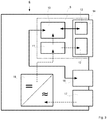
- Figure 1 shows a field device 6 which is arranged in a modular housing 1.
- the housing 1 consists essentially of an elongated square profile 4, which has two undercut longitudinal grooves 5 on each of its side faces for mounting on a carrier structure not shown here and of no further interest.
- the square profile 4 is closed at both ends with the aid of plates which carry the functional elements 8 implemented in the field device 6 and the elements of a base module 9.
- It is a base plate 2, which carries the base module 9, and a cover plate 3, on which a functional module 7 with at least one functional element 8 is arranged.
- FIG. 2 shows schematically the internal structure of the field device 6 from the left side, the functional module 7 with the functional elements 8 mounted on the cover plate 3, for example a lamp, is inserted into the square profile, while the base module 9 is inserted from the right side.
- the base module 9, which is present in every field device, comprises first and foremost a computing unit 10, which with the at least one Functional element 8 exchanges data via a wired or wireless connection.
- the computing unit 10 is supplied with a low voltage of 48 volts from a voltage supply 11, which is applied via an electrical interface 12 within a hybrid interface 14.
- the electrical interface 12 also supplies the at least one functional element 8 of the functional module 7.
- the hybrid interface 14 also includes a communication interface 13 with which data can be exchanged among the field devices within the local network of the automation environment.
- Figure 3 describes a variant of the field device described above, which represents a head station in relation to the automation environment.
- This does not include a functional module 8, but in addition a network interface 16 and a network connection 17.
- a network voltage of 220 volts is applied to a voltage converter 18 via the network connection 17, which converts the applied AC voltage of 220 volts, or 110 volts in the USA converts a direct voltage of 48 volts.
- This 48 volt DC voltage is applied to the voltage supply 11 of the computing unit 10 and is also fed into the electrical interface 12, which is also provided in the base module 9 which is already known and is also present here.
- processing unit 10 communicates here with the network interface 16 and receives requests from an external network, for example the Internet, and sends data packets out of the internal network.
- an external network for example the Internet
- FIG Figure 4 shows another aspect of the invention in a detailed section of a cross section through the housing 1.
- the base plate for its part, is connected to the square profile 4 of the housing 1 via heat transfers 21, here designed as screws, so that in addition the heat on the base plate 2 can be passed on to the square profile.
- the affected housing parts 2 and 4 are made of a thermally conductive material.
- Figure 5 shows an alternative to the previous one Figure 4 , in which the microprocessor 19 mounted on a printed circuit board 20 makes direct contact with the square profile 4, more precisely on the back of the longitudinal grooves 5, via a heat transfer 21 in the form of a thermally conductive plate.
- the heat is introduced directly into the square profile 4 and distributed there so that a large surface is available for dissipation.
- the heat can also be dissipated into the cover plate 3 and / or the base plate 2 via the mounting screws in the opposite direction.
- a modular field device is thus described above which, due to the design of its housing in a polygonal profile, has a high degree of modularization and enables largely standardized components in the form of a base module and variable function modules to be used.
Landscapes
- Engineering & Computer Science (AREA)
- General Physics & Mathematics (AREA)
- Physics & Mathematics (AREA)
- Microelectronics & Electronic Packaging (AREA)
- Theoretical Computer Science (AREA)
- Automation & Control Theory (AREA)
- Human Computer Interaction (AREA)
- General Engineering & Computer Science (AREA)
- Computer Networks & Wireless Communication (AREA)
- Signal Processing (AREA)
- Power Engineering (AREA)
- Computer Hardware Design (AREA)
- Cooling Or The Like Of Electrical Apparatus (AREA)
- Programmable Controllers (AREA)
- Casings For Electric Apparatus (AREA)
Description
Die vorliegende Erfindung betrifft ein modular aufgebautes Feldgerät zum Betrieb an einem Feldbus, umfassend ein Gehäuse mit einem Basismodul, welches eine Recheneinheit zur Prozesssteuerung, eine mit der Recheneinheit datenverbundene Kommunikationsschnittstelle zur Verbindung mit einem lokalen Kommunikationsnetz, sowie eine mit einer Spannungsversorgung der Recheneinheit elektrisch verbundene elektrische Schnittstelle zur Verbindung mit einem lokalen Spannungsnetz aufweist.The present invention relates to a modular field device for operation on a field bus, comprising a housing with a base module, which has a computing unit for process control, a data-connected communication interface to the computing unit for connection to a local communication network, and an electrical one that is electrically connected to a voltage supply of the computing unit Has interface for connection to a local voltage network.
Ein derartiges Feldgerät ist bereits aus der
Ein Feldgerät mit ähnlicher Funktionalität ist auch aus der
Außerdem ist in diesem Zusammenhang ein Gehäuse aus der
Ferner ist auch aus der
Derartige Feldgeräte sind im Stand der Technik bereits weitgehend bekannt und üblich. Im Feldbetrieb erfassen sie Daten und Zustände, regeln oder steuern Prozesse und leiten Messergebnisse an Prozessrechner weiter oder verarbeiten diese direkt weiter. Sie sind in aller Regel spezifisch ausgestaltet und ihrem Einsatzzweck im Feld entsprechend hergerichtet. So wird etwa für Überwachungsaufgaben eine Kamera, für eine Temperaturmessung ein Messfühler, für eine hydraulische Regelungsaufgabe ein Stellventil eingesetzt. Je nach verwendetem Bussystem müssen häufig diese Komponenten noch speziell hergerichtet werden, um über den Bus kommunizieren zu können.Such field devices are already largely known and customary in the prior art. In field operation, they record data and states, regulate or control processes and forward measurement results to process computers or process them directly. As a rule, they are specifically designed and prepared according to their purpose in the field. For example, a camera is used for monitoring tasks, a measuring sensor for temperature measurement, and a control valve for hydraulic control tasks. Depending on the bus system used, these components often have to be specially prepared in order to be able to communicate via the bus.
Auch ist es erforderlich, für die einzelnen Komponenten jeweils vor Ort eine Spannungsversorgung bereitzustellen, was bedeuten kann, dass eine Netzspannung bereitgehalten wird, an der für jedes einzelne Gerät ein für dessen Anforderungen passender Spannungswandler Einsatz findet. Die einzelnen Geräte sind in den seltensten Fällen gegeneinander austauschbar und im Falle eines Geräteausfalls muss das komplette Gerät durch ein anderes ersetzt werden. Dies möchte der Betreiber allerdings schon aus Kostengründen vermeiden, der ansonsten gezwungen ist, unterschiedlichste Geräte vorzuhalten, für den Fall, dass diese benötigt werden könnten.It is also necessary to provide a voltage supply for the individual components in each case on site, which can mean that a mains voltage is kept available at which a voltage converter suitable for its requirements is used for each individual device. The individual devices are rarely interchangeable and in the event of a device failure, the entire device must be replaced by another. However, the operator would like to avoid this for cost reasons, who would otherwise be forced to keep a wide variety of devices available in the event that they might be needed.
Um Prozesse innerhalb der Automatisierungsumgebung zu steuern, sind in der Regel zusätzlich Steuereinheiten mit Mikroprozessoren erforderlich, die mit dem Prozessrechner kommunizieren und dessen komplexen Anweisungen in Steuerbefehle für die einzelnen Feldgeräte umsetzen, sowie auf dem umgekehrten Weg die ermittelten Messwerte für den Prozessrechner aufbereiten oder zu komplexeren Zwischenergebnissen zusammenführen.In order to control processes within the automation environment, additional control units with microprocessors are usually required, which communicate with the process computer and convert its complex instructions into control commands for the individual field devices and, in the opposite direction, prepare the measured values for the process computer or make them more complex Merge intermediate results.
Vor diesem Hintergrund liegt der vorliegenden Erfindung die Aufgabe zu Grunde, ein modulares Feldgerät zu schaffen, welches einen hohen Grad an Modularisierung aufweist und es ermöglicht, weitgehend auf standardisierte Komponenten zurückzugreifen. Hierbei soll nicht nur ein technisches Zusammenspiel zwischen den Komponenten funktionieren, sondern auch eine räumliche Integration erfolgen, um den Aufwand der Verkabelung sowie den logistischen Aufwand der Lagerung und Bereitstellung möglichst weit zu senken.Against this background, the present invention is based on the object of creating a modular field device which has a high degree of modularization and enables standardized components to be used to a large extent. Here, not only should a technical interaction between the components work, but spatial integration should also take place in order to reduce the effort of cabling and the logistical effort of storage and provision as much as possible.
Dies gelingt durch ein Feldgerät gemäß den Merkmalen des Anspruchs 1. Weitere sinnvolle Ausgestaltungen eines solchen Feldgeräts können den Unteransprüchen entnommen werden.This is achieved by a field device according to the features of
Erfindungsgemäß ist vorgesehen, dass ein Feldgerät ein gemeinsames Gehäuse aufweist, in dem alle erforderlichen Komponenten des Feldgeräts aufgenommen werden können. Hierzu ist es vorgesehen, dass ein solches Feldgerät über ein Basismodul verfügt, welchem eine Recheneinheit, eine Kommunikationseinheit und eine Spannungsversorgung zugeordnet sind. Mit einem solchen Basismodul ist jedes Feldgerät ausgestattet, so dass sowohl die Kommunikation über den Feldbus, als auch die Spannungsversorgung sichergestellt ist und das Gerät angesprochen wird und Daten übermitteln kann. Hiervon ausgehend sieht die Erfindung vor, dass das Aufbauprinzip eines solchen Feldgeräts auf einem Gehäuse aus einem Mehrkantprofil aufbaut, welches in einem leeren Zustand von zwei Seiten her verschlossen werden kann. So ist das Basismodul derart aufgebaut, dass es auf einer Basisplatte montiert ist, die von einer Seite her in das Mehrkantprofil eingeschoben wird und diese gleichzeitig verschließt.According to the invention, it is provided that a field device has a common housing in which all necessary components of the field device can be accommodated. For this purpose, it is provided that such a field device has a base module to which a computing unit, a communication unit and a voltage supply are assigned. Each field device is equipped with such a base module, so that communication via the fieldbus as well as the power supply is ensured and the device is addressed and can transmit data. Based on this, the invention provides that the construction principle of such a field device is based on a housing made of a polygonal profile which can be closed from two sides in an empty state. The base module is constructed in such a way that it is mounted on a base plate that is pushed into the polygonal profile from one side and closes it at the same time.
Selbstverständlich kann die Basisplatte hierfür von Anschlüssen, Sicht- und Kommunikationsfenstern jedweder Art durchgriffen werden, jedoch findet der Aufbau des Basismoduls stets gleich und stets auf der an die Form des Mehrkantprofils angepasste Basisplatte statt. In dieser Konfiguration steht bereits die Recheneinheit für Aufgaben aus der Automatisierungsumgebung zur Verfügung. Aufgrund dieser einheitlichen Bestückung eines solchen Mehrkantprofils mit den Basismodulen, welche eine einheitliche Kommunikationsplattform schaffen und eine einheitliche Spannungsversorgung gewährleisten, kann sichergestellt werden, dass alle Feldgeräte die gleiche Basis haben und damit bei Ausfällen nur einheitliche Komponenten ausgetauscht werden müssen. Auf spezielle Geräte kann damit verzichtet werden. Eine Spezialisierung der bis dahin noch auf reine Rechenaufgaben beschränkten Basis-Feldgeräte kann nach Bedarf durch ein Hinzufügen von Funktionsmodulen erfolgen. Diese Funktionsmodule umfassen Funktionseinheiten unterschiedlichster Art, die auf einer Deckelplatte, komplementär zur Basisplatte, auf der noch freien Seite des Mehrkantprofils in dieses eingebracht werden und das Mehrkantprofil somit vollständig verschließen. Beim Einsetzen des Funktionsmoduls in das Mehrkantprofil wird die Funktionseinheit sowohl mit der Spannungsversorgung des Basismoduls verbunden, als auch eine Datenverbindung mit der Recheneinheit aufbauen, über die eine Steuerung der Funktionseinheit durch die Recheneinheit erfolgen kann. Analog zur Basisplatte kann auch die Deckelplatte von dem wenigstens einen Funktionselement durchgriffen sein, Fenster oder Öffnungen aufweisen, durch welche das Funktionselement hindurchwirken kann, oder geeignete Adapter, Anschlüsse, Flanschs und des Weiteren mehr aufweisen, ganz in Abhängigkeit von der Art und Funktionalität des wenigstens einen Funktionselements.Of course, connections, viewing and communication windows of any kind can penetrate the base plate for this purpose, but the structure of the base module is always the same and always takes place on the base plate adapted to the shape of the polygonal profile. In this configuration, the processing unit is already available for tasks from the automation environment. Due to this uniform equipping of such a polygonal profile with the basic modules, which create a uniform communication platform and guarantee a uniform voltage supply, it can be ensured that all field devices have the same basis and that only uniform components have to be replaced in the event of failures. There is no need for special devices. The basic field devices, which were previously limited to pure computing tasks, can be specialized by adding function modules as required. These functional modules include functional units of the most varied of types, which are introduced into the polygonal profile on a cover plate, complementary to the base plate, on the still free side of the polygonal profile and thus completely close the polygonal profile. When the functional module is inserted into the polygonal profile, the functional unit is both connected to the voltage supply of the base module and a data connection is established with the processing unit, via which the processing unit can control the functional unit. Analogous to the base plate, the cover plate can also be penetrated by the at least one functional element, have windows or openings through which the functional element can work, or have suitable adapters, connections, flanges and more, depending on the type and functionality of the at least a functional element.
Im Einzelnen kann ein solches Funktionselement etwa ein Motor, ein Sensor oder eine Sensoranordnung, ein Beleuchtungselement, eine Kamera, eine Arbeitsmaschine, ein Eingabeelement, ein Display oder ein Lautsprecher sein. , Um den Feldbus zu steuern und die Spannung einzuspeisen, sowie um eine Kommunikation mit Geräten außerhalb eines lokalen Kommunikationsnetzes, etwa über das Internet, zu ermöglichen, wird eine Art Kopfstation benötigt, welche neben dem Basismodul auch eine mit der Recheneinheit datenverbundene Netzwerkschnittstelle zur Verbindung mit diesem externen Kommunikationsnetz aufweist. Die Kopfstation stellt in diesem Zusammenhang das Tor zu dem externen Netzwerk dar und kann die Kommunikation zwischen externen Geräten und den einzelnen Feldgeräten steuern und bedarfsweise beschränken. Auch verbindet sie über den mit der Spannungsversorgung der Recheneinheit elektrisch verbundenen Netzanschluss ein öffentliches Energienetz mit dem internen Spannungsnetz der Feldgeräte, so dass diesen eine gemeinsame Netzspannung zur Verfügung steht. Die Vorgabe der Spannung auf dem internen Spannungsnetz erfolgt über einen Spannungswandler, welcher zwischen den Netzanschluss der Kopfstation und die Spannungsversorgung der Recheneinheit zwischengeschaltet ist.In detail, such a functional element can be a motor, a sensor or a sensor arrangement, a lighting element, a camera, a work machine, an input element, a display or a loudspeaker. To control the fieldbus and feed in the voltage, as well as to communicate with devices outside of a local communication network, For example, via the Internet, a type of head-end station is required which, in addition to the base module, also has a network interface that is data-connected to the computing unit for connection to this external communication network. In this context, the head station represents the gateway to the external network and can control and, if necessary, restrict communication between external devices and the individual field devices. It also connects a public energy network to the internal voltage network of the field devices via the network connection electrically connected to the voltage supply of the computing unit, so that a common network voltage is available to them. The specification of the voltage on the internal voltage network takes place via a voltage converter, which is connected between the network connection of the head station and the voltage supply of the computing unit.
Mit einigem Vorteil handelt es sich bei dem Gehäuse um ein langgestrecktes Mehrkantprofil, vorzugsweise ein Dreikant- oder Vierkantprofil, welches zudem auf seiner Umfangswandung wenigstens eine hinter-schnittene Längsnut aufweist. In diese kann zur Befestigung des Feldgeräts an einer Tragvorrichtung ein Nutenstein eingeführt werden, in welchen eine Schraube eingedreht werden und das Gehäuse an der Tragvorrichtung, etwa in Form eines Trägerprofils, einer Traverse oder eines Standgerüsts, fixiert werden kann.With some advantage, the housing is an elongated polygonal profile, preferably a triangular or square profile, which also has at least one undercut longitudinal groove on its peripheral wall. A slot nut can be inserted into this to attach the field device to a support device, into which a screw can be screwed and the housing can be fixed to the support device, for example in the form of a support profile, a cross member or a stand.
Die erfindungsgemäße Lösung hat jedoch auch im Hinblick auf die Kühlung einige Vorteile. Zunächst werden im Basismodul oder dem Funktionsmodul Niederspannungen von vorzugsweise 48 Volt, jedenfalls einer Spannungsebene im Bereich der Kleinstspannung eingesetzt, so dass die Wärmeentwicklung vergleichsweise klein ist. Dann können außerdem Mikroprozessoren eingesetzt werden, die energieeffizient arbeiten und damit lediglich eine geringe Leistungsaufnahme besitzen und nur geringen Platzbedarf haben und damit eine geringe Abwärme produzieren. Die dennoch produzierte Abwärme kann durch eine Kontaktierung einer Heißseite des Mikroprozessors an der Basisplatte oder der Deckelplatte, vorzugsweise unter Zwischenlage einer wärmeleitenden Schicht, in das Gehäuse abgeführt werden. Die Deckelplatte und/oder die Basisplatte sind hierfür aus einem wärmeleitenden Material, vorzugsweise aus Metall und höchst vorzugsweise aus Aluminium oder Kupfer hergestellt. Ferner können die Basisplatte und/oder die Deckelplatte zusätzlich wärmeleitend mit dem ebenfalls wärmeleitenden Mehrkantprofil verbunden sein, so dass auch dessen Außenfläche zur Kühlung der Prozessoren zur Verfügung steht. Schrauben, mit denen die Deckelplatte und/oder die Basisplatte mit dem Mehrkantprofil verbunden sind, können insbesondere die Wärme aus diesen Platten in das Mehrkantprofil ableiten.However, the solution according to the invention also has some advantages with regard to cooling. First, low voltages of preferably 48 volts, at least one voltage level in the range of the extra-low voltage, are used in the base module or the functional module, so that the heat development is comparatively small. Then microprocessors can also be used that work energy-efficiently and therefore only have a low power consumption and only require little space and thus produce little waste heat. The waste heat that is nevertheless produced can be achieved by contacting a hot side of the microprocessor on the base plate or the cover plate, preferably with a thermally conductive one in between Layer to be discharged into the housing. For this purpose, the cover plate and / or the base plate are made from a thermally conductive material, preferably from metal and most preferably from aluminum or copper. Furthermore, the base plate and / or the cover plate can additionally be connected in a thermally conductive manner to the polygonal profile, which is also thermally conductive, so that its outer surface is also available for cooling the processors. Screws with which the cover plate and / or the base plate are connected to the polygonal profile can in particular dissipate the heat from these plates into the polygonal profile.
Alternativ kann der Ableitprozess der Prozessorabwärme auch auf dem Umgekehrten Weg erfolgen. Wird ein Wärmeübergang, etwa in Form eines wärmeleitenden Materialabschnitts, an der Innenwand des Mehrkantprofils angeordnet und kontaktiert die Heißseite des Prozessors diesen Wärmeübergang, so kann die Wärme zunächst in das Mehrkantprofil abfließen und bedarfsweise zusätzlich über die Schrauben in die Basisplatte und/oder die Deckelplatte.Alternatively, the process of dissipating the waste heat from the processor can also take place in the opposite direction. If a heat transfer, for example in the form of a thermally conductive material section, is arranged on the inner wall of the polygonal profile and the hot side of the processor contacts this heat transfer, the heat can initially flow into the polygonal profile and, if necessary, additionally via the screws into the base plate and / or the cover plate.
Für die Kommunikation in der Automatisierungsumgebung wird das Protokoll Ethernet POWERLINK, bzw. ein anderes Ethernet-basiertes Echtzeitprotokoll, bevorzugt. Hinsichtlich des lokalen, internen Spannungsnetzes kommt vorzugsweise ein Niederspannungsnetz zum Einsatz. Bedarfsweise können die zugehörigen Schnittstellen des Basismoduls hierbei zu einer hybriden Schnittstelle zusammengezogen werden, wobei etwa auch ein bekanntes Protokoll wie Power-over-Ethernet (PoE) zum Einsatz kommen kann.The Ethernet POWERLINK protocol or another Ethernet-based real-time protocol is preferred for communication in the automation environment. With regard to the local, internal voltage network, a low-voltage network is preferably used. If necessary, the associated interfaces of the base module can be combined to form a hybrid interface, whereby a known protocol such as Power-over-Ethernet (PoE) can also be used.
Die vorstehend beschriebene Erfindung wird im Folgenden anhand eines Ausführungsbeispiels näher erläutert.The invention described above is explained in more detail below using an exemplary embodiment.
Es zeigen
Figur 1- ein erfindungsgemäßes Feldgerät in einer perspektivischen Darstellung von schräg oben,
Figur 2- einen seitlichen Querschnitt des Feldgeräts gemäß
Figur 1 Figur 3- eine Variante des Feldgeräts gemäß
Figur 5 Figur 4- ein Detail eines seitlichen Querschnitts des Feldgeräts gemäß
Figur 1 Figur 5- ein Detail einer Querschnitts-Draufsicht des Feldgeräts gemäß
Figur 1
- Figure 1
- a field device according to the invention in a perspective view obliquely from above,
- Figure 2
- a lateral cross section of the field device according to
Figure 1 in a schematic block diagram, - Figure 3
- a variant of the field device according to
Figure 5 in a schematic block diagram, - Figure 4
- a detail of a lateral cross section of the field device according to FIG
Figure 1 , as - Figure 5
- a detail of a cross-sectional top view of the field device according to FIG
Figure 1 .
In
Zusätzlich kommuniziert hier die Recheneinheit 10 mit der Netzwerkschnittstelle 16 und nimmt Anfragen von einem externen Netz, etwa dem Internet, entgegen und sendet Datenpakete aus dem internen Netz heraus.In addition, the
Vorstehend beschrieben ist somit ein modulares Feldgerät, welches durch die Bauform seines Gehäuses in einem Mehrkantprofil einen hohen Grad an Modularisierung aufweist und es ermöglicht, weitgehend auf standardisierte Komponenten in Form eines Basismoduls und variabler Funktionsmodule zurückzugreifen.A modular field device is thus described above which, due to the design of its housing in a polygonal profile, has a high degree of modularization and enables largely standardized components in the form of a base module and variable function modules to be used.
- 11
- Gehäusecasing
- 22
- BasisplatteBase plate
- 33
- DeckelplatteCover plate
- 44th
- VierkantprofilSquare profile
- 55
- LängsnutLongitudinal groove
- 66th
- FeldgerätField device
- 77th
- FunktionsmodulFunction module
- 88th
- FunktionseinheitFunctional unit
- 99
- BasismodulBasic module
- 1010
- RecheneinheitArithmetic unit
- 1111
- SpannungsversorgungPower supply
- 1212th
- elektrische Schnittstelleelectrical interface
- 1313th
- KommunikationsschnittstelleCommunication interface
- 1414th
- hybride Schnittstellehybrid interface
- 1515th
- KopfstationHead station
- 1616
- NetzwerkschnittstelleNetwork interface
- 1717th
- NetzanschlussMains connection
- 1818th
- SpannungswandlerVoltage converter
- 1919th
- Mikroprozessormicroprocessor
- 2020th
- LeiterplatteCircuit board
- 2121
- WärmeübergangHeat transfer
Claims (4)
- A modularly constructed field device for operation on a field bus, comprising a housing (1) having a base module (9), which includes a processing unit (10) for process control, a communication interface (13), having a data connection to the processing unit (10), for connection to a local communication network of the automation environment of the field device, and an electrical interface (12), electrically connected to a power supply (11) of the processing unit (10), for connection to a local power grid, wherein a functional module (7) is associated with the housing (1), which includes at least one functional element (8), which has a data connection to the processing unit (10) and an electrical connection to the electrical interface (12), so that both the communication via the field bus and also the power supply of the functional module (7) are ensured, wherein the at least one functional element (8) is a motor, a sensor or a sensor arrangement, an illumination element, a camera, a work machine, an input element, a display, or a loudspeaker, and wherein the communication interface (13), having a data connection to the processing unit (10), for connection to a local communication network, and also the electrical interface (12), having an electrical connection to a power supply (11) of the processing unit (10), for connection to a local power grid are combined into a shared hybrid interface (14), preferably a Power-over-Ethernet (PoE) interface,
characterized in that the housing (1) is designed as an elongated polygonal profile (4) enclosing an inner cavity, into the inner cavity of which the base module (9) fastened on a base plate (2) protrudes at the end and closes it by means of the base plate (2), wherein the at least one functional element (8) is fastened on a cover plate (3), wherein the functional module (7) protrudes at the end into the inner cavity of the polygonal profile (4) and closes it by means of the cover plate (3) and wherein the polygonal profile (4) includes at least one undercut longitudinal groove (5) on its circumferential wall, in which a groove block is insertable for fastening of the field device (6) on a support device, into which groove block a screw can be screwed and the housing can be fixed on the support device. - The field device according to any one of the preceding claims, characterized in that the housing (1) includes a network interface (16), having a data connection to the processing unit (10), for connection to an external communication network, and a grid connection (17), electrically connected to the power supply (11) of the processing unit (10), for connection to an external power grid, wherein a voltage converter (18) is connected between the grid connection (17) and the power supply (11) of the processing unit (10).
- The field device according to any one of the preceding claims, characterized in that microprocessors (19) of the base module (9) and/or the functional module (7) are connected in a heat-conducting manner to the base plate (2) and/or the cover plate (3) and the base plate (2) and/or the cover plate (3) is in turn connected in a heat-conducting manner to the polygonal profile (4).
- The field device according to any one of the preceding claims, characterized in that microprocessors (19) are associated with the housing (1), which are connected to the polygonal profile (4) with a heat-conductive layer interposed.
Priority Applications (1)
| Application Number | Priority Date | Filing Date | Title |
|---|---|---|---|
| PL18732642T PL3632196T3 (en) | 2017-05-31 | 2018-05-17 | Field device of modular construction |
Applications Claiming Priority (2)
| Application Number | Priority Date | Filing Date | Title |
|---|---|---|---|
| DE102017111998.1A DE102017111998A1 (en) | 2017-05-31 | 2017-05-31 | MODULAR BUILT FIELD DEVICE |
| PCT/DE2018/100478 WO2018219400A1 (en) | 2017-05-31 | 2018-05-17 | Field device of modular construction |
Publications (2)
| Publication Number | Publication Date |
|---|---|
| EP3632196A1 EP3632196A1 (en) | 2020-04-08 |
| EP3632196B1 true EP3632196B1 (en) | 2021-04-21 |
Family
ID=62684559
Family Applications (1)
| Application Number | Title | Priority Date | Filing Date |
|---|---|---|---|
| EP18732642.6A Active EP3632196B1 (en) | 2017-05-31 | 2018-05-17 | Field device of modular construction |
Country Status (8)
| Country | Link |
|---|---|
| US (1) | US10921867B2 (en) |
| EP (1) | EP3632196B1 (en) |
| CN (1) | CN110651536A (en) |
| DE (2) | DE102017111998A1 (en) |
| ES (1) | ES2881181T3 (en) |
| PL (1) | PL3632196T3 (en) |
| PT (1) | PT3632196T (en) |
| WO (1) | WO2018219400A1 (en) |
Families Citing this family (2)
| Publication number | Priority date | Publication date | Assignee | Title |
|---|---|---|---|---|
| DE102018133647A1 (en) * | 2018-12-28 | 2020-07-02 | Beckhoff Automation Gmbh | Control cabinet system consisting of basic module and function modules as well as function module |
| US11202378B1 (en) * | 2020-07-30 | 2021-12-14 | Baidu Usa Llc | Modular infrastructure for compute and storage clusters |
Family Cites Families (26)
| Publication number | Priority date | Publication date | Assignee | Title |
|---|---|---|---|---|
| US4656559A (en) * | 1984-05-10 | 1987-04-07 | Ultima Electronics Ltd. | Holder and heat sink for electronic components |
| DE29716575U1 (en) * | 1997-09-15 | 1997-11-13 | Siemens AG, 80333 München | Fieldbus controlled automation device |
| DE29906804U1 (en) * | 1999-04-19 | 1999-07-08 | Stegmann Max Antriebstech | Positioning and actuator |
| DE20003279U1 (en) * | 2000-02-23 | 2000-04-20 | Berthold Sichert GmbH, 12277 Berlin | Distribution cabinet |
| US7844365B2 (en) | 2000-05-12 | 2010-11-30 | Rosemount Inc. | Field-mounted process device |
| AU2003214698A1 (en) * | 2002-04-06 | 2003-10-27 | Zalman Tech Co., Ltd | Chipset cooling device of video graphic adapter card |
| JP4085089B2 (en) * | 2002-10-14 | 2008-04-30 | シーメンス アクチエンゲゼルシヤフト | Method for assembling circuit modules, circuit modules and crimp strips |
| JP2009503952A (en) * | 2005-07-20 | 2009-01-29 | ローズマウント インコーポレイテッド | Field device with power supply via Ethernet |
| US8036231B2 (en) * | 2005-08-09 | 2011-10-11 | Adc Telecommunications, Inc. | Wall-mountable connector |
| DE102006019555B3 (en) * | 2006-04-27 | 2007-11-22 | Abb Patent Gmbh | Measuring transducer for use in process plant, has two containers having respective threaded connections with transformer that is made of two parts, where one part is arranged in one of containers in elastic manner by pressure spring |
| WO2007140467A2 (en) * | 2006-05-31 | 2007-12-06 | Akros Silicon, Inc. | Ethernet module |
| DE202009005875U1 (en) * | 2009-04-17 | 2009-10-08 | Heliocentris Energiesysteme Gmbh | Modular fuel cell system |
| US8674823B1 (en) * | 2009-05-12 | 2014-03-18 | Plug ID, LLC. | Power management system |
| US20120224337A1 (en) * | 2011-03-04 | 2012-09-06 | Bodine Joel Cristopher | Compact communication system |
| CN202111966U (en) * | 2011-06-23 | 2012-01-11 | 西安市伟创科技有限责任公司 | Upper frame type magnesium-aluminum profile case |
| US9727511B2 (en) * | 2011-12-30 | 2017-08-08 | Bedrock Automation Platforms Inc. | Input/output module with multi-channel switching capability |
| DE202012101067U1 (en) * | 2012-03-26 | 2012-07-10 | Ferrofacta Gmbh | Compensation device for thermal expansion |
| DE102012006787A1 (en) * | 2012-04-04 | 2013-10-10 | Inter Control Hermann Köhler Elektrik GmbH & Co. KG | Expandable housing for electrical components, intermediate housing part for the expandable housing, and method for manufacturing and mounting the housing |
| US9860071B2 (en) * | 2013-03-01 | 2018-01-02 | Computer Performance, Inc. | Power over ethernet injector |
| US9408335B2 (en) * | 2013-06-28 | 2016-08-02 | Cisco Technology, Inc. | ICM optimization and standardization for automation |
| DE102014109783A1 (en) * | 2014-07-11 | 2016-01-14 | Pilz Gmbh & Co. Kg | Automation device with mounting aid |
| KR101575268B1 (en) * | 2014-09-30 | 2015-12-07 | 현대오트론 주식회사 | Electronic control apparatus for vehicle using coupling member and method thereof |
| WO2016149549A1 (en) * | 2015-03-18 | 2016-09-22 | Iota Engineering Llc | Power over ethernet emergency lighting system |
| DE102015107306A1 (en) * | 2015-05-11 | 2016-11-17 | Endress + Hauser Gmbh + Co. Kg | Field device for use in process automation |
| US11706895B2 (en) * | 2016-07-19 | 2023-07-18 | Pure Storage, Inc. | Independent scaling of compute resources and storage resources in a storage system |
| US10289572B2 (en) * | 2016-10-14 | 2019-05-14 | General Electric Company | Industrial control adjacent input-output modules and methods thereof |
-
2017
- 2017-05-31 DE DE102017111998.1A patent/DE102017111998A1/en not_active Withdrawn
-
2018
- 2018-05-17 EP EP18732642.6A patent/EP3632196B1/en active Active
- 2018-05-17 WO PCT/DE2018/100478 patent/WO2018219400A1/en active Application Filing
- 2018-05-17 US US16/605,532 patent/US10921867B2/en active Active
- 2018-05-17 DE DE112018002818.6T patent/DE112018002818A5/en not_active Withdrawn
- 2018-05-17 PL PL18732642T patent/PL3632196T3/en unknown
- 2018-05-17 CN CN201880032055.7A patent/CN110651536A/en active Pending
- 2018-05-17 PT PT187326426T patent/PT3632196T/en unknown
- 2018-05-17 ES ES18732642T patent/ES2881181T3/en active Active
Non-Patent Citations (1)
| Title |
|---|
| None * |
Also Published As
| Publication number | Publication date |
|---|---|
| US10921867B2 (en) | 2021-02-16 |
| DE102017111998A1 (en) | 2018-12-06 |
| PT3632196T (en) | 2021-07-12 |
| PL3632196T3 (en) | 2021-11-15 |
| CN110651536A (en) | 2020-01-03 |
| EP3632196A1 (en) | 2020-04-08 |
| WO2018219400A1 (en) | 2018-12-06 |
| DE112018002818A5 (en) | 2020-03-05 |
| ES2881181T3 (en) | 2021-11-29 |
| US20200125147A1 (en) | 2020-04-23 |
Similar Documents
| Publication | Publication Date | Title |
|---|---|---|
| EP1175133B1 (en) | Combination of devices with at least two robots and a control cabinet | |
| EP3632196B1 (en) | Field device of modular construction | |
| DE102017201410B3 (en) | Cooling device and robot control device with such a cooling device | |
| DE10204866A1 (en) | Wärmeableitmodul | |
| DE112015004024T5 (en) | Circuit board and electrical distributor | |
| EP3884741B1 (en) | Switching cabinet system consisting of a base module and functional modules, and functional module | |
| DE102004008461A1 (en) | housing arrangement | |
| AT399075B (en) | REAR PANEL FOR A HOUSING TO RECEIVE ELECTRICAL ASSEMBLIES | |
| EP3214670B1 (en) | Battery module for battery devices comprising a number of such battery modules | |
| EP1649736B1 (en) | Cooling device for an electronic component, especially for a microprocessor | |
| DE112014005950T5 (en) | Electronic device with cooling function | |
| DE10057556A1 (en) | Tripod head for medical surveillance and treatment systems with carrier profile and apparatus carriage | |
| EP2699066B1 (en) | Locking element for locking a cover plate to a module rail | |
| EP4031412B1 (en) | Lighting device for a motor vehicle headlight | |
| EP3418629B1 (en) | Luminaire for tunnels | |
| WO2008083878A1 (en) | Fixing element for printed circuit boards | |
| EP3096593B1 (en) | Device holder panel of a satellite | |
| DE102014010682A1 (en) | Temperature measuring arrangement for a switchgear | |
| EP2670003B1 (en) | Connection device assembly with bearing rail | |
| DE102020132650B4 (en) | ELECTRONIC HOUSING FOR ONE HUB TO CONTROL SEVERAL ACTUATORS | |
| DE102008055718B4 (en) | Camera Housings | |
| EP3406387A1 (en) | Welding current source and system for fixing a component on the top of their housings | |
| DE102005034439B3 (en) | Cooling arrangement for computer system, has cooling device fasted at threaded holes of base plate by screws, where plate has stampings in which spacers are introduced by sliding/rotary motion such that spacers are retained in area of holes | |
| DE10156359C1 (en) | Mounting of casing with panel in nineteen inch rack system, employs screw-in pegs to support panel whilst first fastening screws are tightened | |
| DE2608125B2 (en) | Use for frames for electrical transmission technology |
Legal Events
| Date | Code | Title | Description |
|---|---|---|---|
| STAA | Information on the status of an ep patent application or granted ep patent |
Free format text: STATUS: UNKNOWN |
|
| STAA | Information on the status of an ep patent application or granted ep patent |
Free format text: STATUS: THE INTERNATIONAL PUBLICATION HAS BEEN MADE |
|
| PUAI | Public reference made under article 153(3) epc to a published international application that has entered the european phase |
Free format text: ORIGINAL CODE: 0009012 |
|
| STAA | Information on the status of an ep patent application or granted ep patent |
Free format text: STATUS: REQUEST FOR EXAMINATION WAS MADE |
|
| 17P | Request for examination filed |
Effective date: 20191009 |
|
| AK | Designated contracting states |
Kind code of ref document: A1 Designated state(s): AL AT BE BG CH CY CZ DE DK EE ES FI FR GB GR HR HU IE IS IT LI LT LU LV MC MK MT NL NO PL PT RO RS SE SI SK SM TR |
|
| AX | Request for extension of the european patent |
Extension state: BA ME |
|
| DAV | Request for validation of the european patent (deleted) | ||
| DAX | Request for extension of the european patent (deleted) | ||
| GRAP | Despatch of communication of intention to grant a patent |
Free format text: ORIGINAL CODE: EPIDOSNIGR1 |
|
| STAA | Information on the status of an ep patent application or granted ep patent |
Free format text: STATUS: GRANT OF PATENT IS INTENDED |
|
| INTG | Intention to grant announced |
Effective date: 20201119 |
|
| RIN1 | Information on inventor provided before grant (corrected) |
Inventor name: BIHLMAIER, ANDREAS Inventor name: LIEDKE, JENS Inventor name: MINTENBECK, JULIEN |
|
| GRAJ | Information related to disapproval of communication of intention to grant by the applicant or resumption of examination proceedings by the epo deleted |
Free format text: ORIGINAL CODE: EPIDOSDIGR1 |
|
| STAA | Information on the status of an ep patent application or granted ep patent |
Free format text: STATUS: REQUEST FOR EXAMINATION WAS MADE |
|
| GRAP | Despatch of communication of intention to grant a patent |
Free format text: ORIGINAL CODE: EPIDOSNIGR1 |
|
| STAA | Information on the status of an ep patent application or granted ep patent |
Free format text: STATUS: GRANT OF PATENT IS INTENDED |
|
| INTC | Intention to grant announced (deleted) | ||
| RIC1 | Information provided on ipc code assigned before grant |
Ipc: G01D 21/00 20060101ALI20210203BHEP Ipc: H05K 7/14 20060101AFI20210203BHEP Ipc: G01D 11/24 20060101ALI20210203BHEP |
|
| GRAS | Grant fee paid |
Free format text: ORIGINAL CODE: EPIDOSNIGR3 |
|
| GRAA | (expected) grant |
Free format text: ORIGINAL CODE: 0009210 |
|
| STAA | Information on the status of an ep patent application or granted ep patent |
Free format text: STATUS: THE PATENT HAS BEEN GRANTED |
|
| INTG | Intention to grant announced |
Effective date: 20210301 |
|
| AK | Designated contracting states |
Kind code of ref document: B1 Designated state(s): AL AT BE BG CH CY CZ DE DK EE ES FI FR GB GR HR HU IE IS IT LI LT LU LV MC MK MT NL NO PL PT RO RS SE SI SK SM TR |
|
| REG | Reference to a national code |
Ref country code: GB Ref legal event code: FG4D Free format text: NOT ENGLISH |
|
| REG | Reference to a national code |
Ref country code: CH Ref legal event code: EP |
|
| REG | Reference to a national code |
Ref country code: DE Ref legal event code: R096 Ref document number: 502018004928 Country of ref document: DE Ref country code: IE Ref legal event code: FG4D Free format text: LANGUAGE OF EP DOCUMENT: GERMAN |
|
| REG | Reference to a national code |
Ref country code: AT Ref legal event code: REF Ref document number: 1386026 Country of ref document: AT Kind code of ref document: T Effective date: 20210515 |
|
| REG | Reference to a national code |
Ref country code: PT Ref legal event code: SC4A Ref document number: 3632196 Country of ref document: PT Date of ref document: 20210712 Kind code of ref document: T Free format text: AVAILABILITY OF NATIONAL TRANSLATION Effective date: 20210705 |
|
| REG | Reference to a national code |
Ref country code: LT Ref legal event code: MG9D |
|
| PGFP | Annual fee paid to national office [announced via postgrant information from national office to epo] |
Ref country code: ES Payment date: 20210622 Year of fee payment: 4 |
|
| REG | Reference to a national code |
Ref country code: NL Ref legal event code: MP Effective date: 20210421 |
|
| PG25 | Lapsed in a contracting state [announced via postgrant information from national office to epo] |
Ref country code: NL Free format text: LAPSE BECAUSE OF FAILURE TO SUBMIT A TRANSLATION OF THE DESCRIPTION OR TO PAY THE FEE WITHIN THE PRESCRIBED TIME-LIMIT Effective date: 20210421 Ref country code: BG Free format text: LAPSE BECAUSE OF FAILURE TO SUBMIT A TRANSLATION OF THE DESCRIPTION OR TO PAY THE FEE WITHIN THE PRESCRIBED TIME-LIMIT Effective date: 20210721 Ref country code: FI Free format text: LAPSE BECAUSE OF FAILURE TO SUBMIT A TRANSLATION OF THE DESCRIPTION OR TO PAY THE FEE WITHIN THE PRESCRIBED TIME-LIMIT Effective date: 20210421 Ref country code: LT Free format text: LAPSE BECAUSE OF FAILURE TO SUBMIT A TRANSLATION OF THE DESCRIPTION OR TO PAY THE FEE WITHIN THE PRESCRIBED TIME-LIMIT Effective date: 20210421 Ref country code: HR Free format text: LAPSE BECAUSE OF FAILURE TO SUBMIT A TRANSLATION OF THE DESCRIPTION OR TO PAY THE FEE WITHIN THE PRESCRIBED TIME-LIMIT Effective date: 20210421 |
|
| PGFP | Annual fee paid to national office [announced via postgrant information from national office to epo] |
Ref country code: FR Payment date: 20210719 Year of fee payment: 4 Ref country code: CZ Payment date: 20210622 Year of fee payment: 4 |
|
| REG | Reference to a national code |
Ref country code: ES Ref legal event code: FG2A Ref document number: 2881181 Country of ref document: ES Kind code of ref document: T3 Effective date: 20211129 |
|
| PG25 | Lapsed in a contracting state [announced via postgrant information from national office to epo] |
Ref country code: GR Free format text: LAPSE BECAUSE OF FAILURE TO SUBMIT A TRANSLATION OF THE DESCRIPTION OR TO PAY THE FEE WITHIN THE PRESCRIBED TIME-LIMIT Effective date: 20210722 Ref country code: IS Free format text: LAPSE BECAUSE OF FAILURE TO SUBMIT A TRANSLATION OF THE DESCRIPTION OR TO PAY THE FEE WITHIN THE PRESCRIBED TIME-LIMIT Effective date: 20210821 Ref country code: LV Free format text: LAPSE BECAUSE OF FAILURE TO SUBMIT A TRANSLATION OF THE DESCRIPTION OR TO PAY THE FEE WITHIN THE PRESCRIBED TIME-LIMIT Effective date: 20210421 Ref country code: NO Free format text: LAPSE BECAUSE OF FAILURE TO SUBMIT A TRANSLATION OF THE DESCRIPTION OR TO PAY THE FEE WITHIN THE PRESCRIBED TIME-LIMIT Effective date: 20210721 Ref country code: SE Free format text: LAPSE BECAUSE OF FAILURE TO SUBMIT A TRANSLATION OF THE DESCRIPTION OR TO PAY THE FEE WITHIN THE PRESCRIBED TIME-LIMIT Effective date: 20210421 Ref country code: RS Free format text: LAPSE BECAUSE OF FAILURE TO SUBMIT A TRANSLATION OF THE DESCRIPTION OR TO PAY THE FEE WITHIN THE PRESCRIBED TIME-LIMIT Effective date: 20210421 |
|
| PGFP | Annual fee paid to national office [announced via postgrant information from national office to epo] |
Ref country code: DE Payment date: 20210713 Year of fee payment: 4 Ref country code: CH Payment date: 20210719 Year of fee payment: 4 |
|
| PGFP | Annual fee paid to national office [announced via postgrant information from national office to epo] |
Ref country code: PT Payment date: 20210708 Year of fee payment: 4 |
|
| REG | Reference to a national code |
Ref country code: DE Ref legal event code: R097 Ref document number: 502018004928 Country of ref document: DE |
|
| PG25 | Lapsed in a contracting state [announced via postgrant information from national office to epo] |
Ref country code: EE Free format text: LAPSE BECAUSE OF FAILURE TO SUBMIT A TRANSLATION OF THE DESCRIPTION OR TO PAY THE FEE WITHIN THE PRESCRIBED TIME-LIMIT Effective date: 20210421 Ref country code: SK Free format text: LAPSE BECAUSE OF FAILURE TO SUBMIT A TRANSLATION OF THE DESCRIPTION OR TO PAY THE FEE WITHIN THE PRESCRIBED TIME-LIMIT Effective date: 20210421 Ref country code: DK Free format text: LAPSE BECAUSE OF FAILURE TO SUBMIT A TRANSLATION OF THE DESCRIPTION OR TO PAY THE FEE WITHIN THE PRESCRIBED TIME-LIMIT Effective date: 20210421 Ref country code: LU Free format text: LAPSE BECAUSE OF NON-PAYMENT OF DUE FEES Effective date: 20210517 Ref country code: MC Free format text: LAPSE BECAUSE OF FAILURE TO SUBMIT A TRANSLATION OF THE DESCRIPTION OR TO PAY THE FEE WITHIN THE PRESCRIBED TIME-LIMIT Effective date: 20210421 Ref country code: SM Free format text: LAPSE BECAUSE OF FAILURE TO SUBMIT A TRANSLATION OF THE DESCRIPTION OR TO PAY THE FEE WITHIN THE PRESCRIBED TIME-LIMIT Effective date: 20210421 Ref country code: RO Free format text: LAPSE BECAUSE OF FAILURE TO SUBMIT A TRANSLATION OF THE DESCRIPTION OR TO PAY THE FEE WITHIN THE PRESCRIBED TIME-LIMIT Effective date: 20210421 |
|
| REG | Reference to a national code |
Ref country code: BE Ref legal event code: MM Effective date: 20210531 |
|
| PLBE | No opposition filed within time limit |
Free format text: ORIGINAL CODE: 0009261 |
|
| STAA | Information on the status of an ep patent application or granted ep patent |
Free format text: STATUS: NO OPPOSITION FILED WITHIN TIME LIMIT |
|
| 26N | No opposition filed |
Effective date: 20220124 |
|
| PG25 | Lapsed in a contracting state [announced via postgrant information from national office to epo] |
Ref country code: IE Free format text: LAPSE BECAUSE OF NON-PAYMENT OF DUE FEES Effective date: 20210517 |
|
| PG25 | Lapsed in a contracting state [announced via postgrant information from national office to epo] |
Ref country code: IS Free format text: LAPSE BECAUSE OF FAILURE TO SUBMIT A TRANSLATION OF THE DESCRIPTION OR TO PAY THE FEE WITHIN THE PRESCRIBED TIME-LIMIT Effective date: 20210821 Ref country code: AL Free format text: LAPSE BECAUSE OF FAILURE TO SUBMIT A TRANSLATION OF THE DESCRIPTION OR TO PAY THE FEE WITHIN THE PRESCRIBED TIME-LIMIT Effective date: 20210421 |
|
| PGFP | Annual fee paid to national office [announced via postgrant information from national office to epo] |
Ref country code: IT Payment date: 20210531 Year of fee payment: 4 |
|
| PG25 | Lapsed in a contracting state [announced via postgrant information from national office to epo] |
Ref country code: BE Free format text: LAPSE BECAUSE OF NON-PAYMENT OF DUE FEES Effective date: 20210531 |
|
| PGFP | Annual fee paid to national office [announced via postgrant information from national office to epo] |
Ref country code: PL Payment date: 20210622 Year of fee payment: 4 |
|
| REG | Reference to a national code |
Ref country code: DE Ref legal event code: R119 Ref document number: 502018004928 Country of ref document: DE |
|
| REG | Reference to a national code |
Ref country code: CH Ref legal event code: PL |
|
| GBPC | Gb: european patent ceased through non-payment of renewal fee |
Effective date: 20220517 |
|
| PG25 | Lapsed in a contracting state [announced via postgrant information from national office to epo] |
Ref country code: LI Free format text: LAPSE BECAUSE OF NON-PAYMENT OF DUE FEES Effective date: 20220531 Ref country code: CZ Free format text: LAPSE BECAUSE OF NON-PAYMENT OF DUE FEES Effective date: 20220517 Ref country code: CH Free format text: LAPSE BECAUSE OF NON-PAYMENT OF DUE FEES Effective date: 20220531 |
|
| PG25 | Lapsed in a contracting state [announced via postgrant information from national office to epo] |
Ref country code: PT Free format text: LAPSE BECAUSE OF NON-PAYMENT OF DUE FEES Effective date: 20230217 Ref country code: FR Free format text: LAPSE BECAUSE OF NON-PAYMENT OF DUE FEES Effective date: 20220531 |
|
| PG25 | Lapsed in a contracting state [announced via postgrant information from national office to epo] |
Ref country code: GB Free format text: LAPSE BECAUSE OF NON-PAYMENT OF DUE FEES Effective date: 20220517 Ref country code: DE Free format text: LAPSE BECAUSE OF NON-PAYMENT OF DUE FEES Effective date: 20221201 |
|
| REG | Reference to a national code |
Ref country code: ES Ref legal event code: FD2A Effective date: 20230626 |
|
| PG25 | Lapsed in a contracting state [announced via postgrant information from national office to epo] |
Ref country code: CY Free format text: LAPSE BECAUSE OF FAILURE TO SUBMIT A TRANSLATION OF THE DESCRIPTION OR TO PAY THE FEE WITHIN THE PRESCRIBED TIME-LIMIT Effective date: 20210421 |
|
| PG25 | Lapsed in a contracting state [announced via postgrant information from national office to epo] |
Ref country code: IT Free format text: LAPSE BECAUSE OF NON-PAYMENT OF DUE FEES Effective date: 20220517 Ref country code: HU Free format text: LAPSE BECAUSE OF FAILURE TO SUBMIT A TRANSLATION OF THE DESCRIPTION OR TO PAY THE FEE WITHIN THE PRESCRIBED TIME-LIMIT; INVALID AB INITIO Effective date: 20180517 Ref country code: ES Free format text: LAPSE BECAUSE OF NON-PAYMENT OF DUE FEES Effective date: 20220518 |
|
| PG25 | Lapsed in a contracting state [announced via postgrant information from national office to epo] |
Ref country code: MK Free format text: LAPSE BECAUSE OF FAILURE TO SUBMIT A TRANSLATION OF THE DESCRIPTION OR TO PAY THE FEE WITHIN THE PRESCRIBED TIME-LIMIT Effective date: 20210421 |
|
| PG25 | Lapsed in a contracting state [announced via postgrant information from national office to epo] |
Ref country code: PL Free format text: LAPSE BECAUSE OF NON-PAYMENT OF DUE FEES Effective date: 20220517 |
|
| PG25 | Lapsed in a contracting state [announced via postgrant information from national office to epo] |
Ref country code: TR Free format text: LAPSE BECAUSE OF FAILURE TO SUBMIT A TRANSLATION OF THE DESCRIPTION OR TO PAY THE FEE WITHIN THE PRESCRIBED TIME-LIMIT Effective date: 20210421 |
|
| REG | Reference to a national code |
Ref country code: AT Ref legal event code: MM01 Ref document number: 1386026 Country of ref document: AT Kind code of ref document: T Effective date: 20230517 |
|
| PG25 | Lapsed in a contracting state [announced via postgrant information from national office to epo] |
Ref country code: AT Free format text: LAPSE BECAUSE OF NON-PAYMENT OF DUE FEES Effective date: 20230517 |
|
| PG25 | Lapsed in a contracting state [announced via postgrant information from national office to epo] |
Ref country code: AT Free format text: LAPSE BECAUSE OF NON-PAYMENT OF DUE FEES Effective date: 20230517 |