EP3631908B1 - Dry mate rotatable connector - Google Patents
Dry mate rotatable connector Download PDFInfo
- Publication number
- EP3631908B1 EP3631908B1 EP18806795.3A EP18806795A EP3631908B1 EP 3631908 B1 EP3631908 B1 EP 3631908B1 EP 18806795 A EP18806795 A EP 18806795A EP 3631908 B1 EP3631908 B1 EP 3631908B1
- Authority
- EP
- European Patent Office
- Prior art keywords
- connection interface
- electrical connector
- coupler
- conductive
- linear contact
- Prior art date
- Legal status (The legal status is an assumption and is not a legal conclusion. Google has not performed a legal analysis and makes no representation as to the accuracy of the status listed.)
- Active
Links
Images



Classifications
-
- H—ELECTRICITY
- H01—ELECTRIC ELEMENTS
- H01R—ELECTRICALLY-CONDUCTIVE CONNECTIONS; STRUCTURAL ASSOCIATIONS OF A PLURALITY OF MUTUALLY-INSULATED ELECTRICAL CONNECTING ELEMENTS; COUPLING DEVICES; CURRENT COLLECTORS
- H01R13/00—Details of coupling devices of the kinds covered by groups H01R12/70 or H01R24/00 - H01R33/00
- H01R13/46—Bases; Cases
- H01R13/52—Dustproof, splashproof, drip-proof, waterproof, or flameproof cases
- H01R13/5219—Sealing means between coupling parts, e.g. interfacial seal
-
- H—ELECTRICITY
- H01—ELECTRIC ELEMENTS
- H01R—ELECTRICALLY-CONDUCTIVE CONNECTIONS; STRUCTURAL ASSOCIATIONS OF A PLURALITY OF MUTUALLY-INSULATED ELECTRICAL CONNECTING ELEMENTS; COUPLING DEVICES; CURRENT COLLECTORS
- H01R35/00—Flexible or turnable line connectors, i.e. the rotation angle being limited
-
- H—ELECTRICITY
- H01—ELECTRIC ELEMENTS
- H01R—ELECTRICALLY-CONDUCTIVE CONNECTIONS; STRUCTURAL ASSOCIATIONS OF A PLURALITY OF MUTUALLY-INSULATED ELECTRICAL CONNECTING ELEMENTS; COUPLING DEVICES; CURRENT COLLECTORS
- H01R13/00—Details of coupling devices of the kinds covered by groups H01R12/70 or H01R24/00 - H01R33/00
- H01R13/02—Contact members
- H01R13/15—Pins, blades or sockets having separate spring member for producing or increasing contact pressure
- H01R13/17—Pins, blades or sockets having separate spring member for producing or increasing contact pressure with spring member on the pin
-
- H—ELECTRICITY
- H01—ELECTRIC ELEMENTS
- H01R—ELECTRICALLY-CONDUCTIVE CONNECTIONS; STRUCTURAL ASSOCIATIONS OF A PLURALITY OF MUTUALLY-INSULATED ELECTRICAL CONNECTING ELEMENTS; COUPLING DEVICES; CURRENT COLLECTORS
- H01R31/00—Coupling parts supported only by co-operation with counterpart
- H01R31/06—Intermediate parts for linking two coupling parts, e.g. adapter
-
- H—ELECTRICITY
- H01—ELECTRIC ELEMENTS
- H01R—ELECTRICALLY-CONDUCTIVE CONNECTIONS; STRUCTURAL ASSOCIATIONS OF A PLURALITY OF MUTUALLY-INSULATED ELECTRICAL CONNECTING ELEMENTS; COUPLING DEVICES; CURRENT COLLECTORS
- H01R11/00—Individual connecting elements providing two or more spaced connecting locations for conductive members which are, or may be, thereby interconnected, e.g. end pieces for wires or cables supported by the wire or cable and having means for facilitating electrical connection to some other wire, terminal, or conductive member, blocks of binding posts
- H01R11/03—Individual connecting elements providing two or more spaced connecting locations for conductive members which are, or may be, thereby interconnected, e.g. end pieces for wires or cables supported by the wire or cable and having means for facilitating electrical connection to some other wire, terminal, or conductive member, blocks of binding posts characterised by the relationship between the connecting locations
- H01R11/09—Individual connecting elements providing two or more spaced connecting locations for conductive members which are, or may be, thereby interconnected, e.g. end pieces for wires or cables supported by the wire or cable and having means for facilitating electrical connection to some other wire, terminal, or conductive member, blocks of binding posts characterised by the relationship between the connecting locations the connecting locations being identical
-
- H—ELECTRICITY
- H01—ELECTRIC ELEMENTS
- H01R—ELECTRICALLY-CONDUCTIVE CONNECTIONS; STRUCTURAL ASSOCIATIONS OF A PLURALITY OF MUTUALLY-INSULATED ELECTRICAL CONNECTING ELEMENTS; COUPLING DEVICES; CURRENT COLLECTORS
- H01R24/00—Two-part coupling devices, or either of their cooperating parts, characterised by their overall structure
- H01R24/38—Two-part coupling devices, or either of their cooperating parts, characterised by their overall structure having concentrically or coaxially arranged contacts
Definitions
- This specification relates to an electrical connector assembly.
- Electrical connector assemblies are used in high temperature and high pressure environments.
- Current electrical connector assemblies that are used in such environments usually require the use of O-rings and a central cartridge to provide high temperature and pressure resistance.
- This configuration presents a drawback as O-rings require frequent inspection and maintenance in order to reduce the potential for breakdown and failure of the electrical connector.
- the central cartridge includes other components that also require additional inspection and maintenance to ensure continued reliability.
- US3,060,417 discloses a condition responsive network insensitive to electrical leakage.
- a coupler for electrical connectors includes a body having a first end and a second end opposite the first end.
- the coupler further includes a first connection interface positioned at the first end of the body, the first connection interface having a first set of conductive rings.
- the coupler further includes a second connection interface positioned at the second end of the body, the second connection interface having a second set of conductive rings electrically connected to the first set of conductive rings, wherein the first connection interface and the second connection interface are formed in at least one of a stepped conic shape or an inverted stepped conic shape, wherein the rings of the first set of conductive rings and of the second set of conductive rings are configured to interface with linear contact members of a connection interface of connectors.
- the electrical connector includes a connection interface being formed in at least one of an inverted stepped conic shape or a stepped conic shape, the connection interface being configured to interface with a coupler for an electrical connector.
- the electrical connector further includes one or more linear contact members positioned on the connection interface, each linear contact member being configured to contact a conductive ring on the coupler.
- An electrical connector system comprising both the coupler and the electrical connector.
- FIG. 1 is an exploded perspective view of an electrical connector system 100 having a coupler for electrical connectors (coupler) 101, a first electrical connector 111, and a second electrical connector 121 according to various aspects of the invention.
- the coupler 101 has a first end 103, a second end 105 opposite the first end 103, a first connection interface 107 positioned at the first end 103, and a second connection interface 109 positioned at the second end 105.
- the first connection interface 107 includes a first conductive ring set 116 disposed on the first connection interface 107.
- the second connection interface 109 includes a second conductive ring set 118 disposed on the second connection interface 109.
- the first conductive ring set 116 and the second conductive ring set 118 may each include one or more conductive rings within their respective set.
- the first conductive ring set 116 on the first connection interface 107 may be electrically connected to the second conductive ring set 118 on the second connection interface 109.
- Each ring within the first conductive ring set 116 may be individually connected to a corresponding ring within the second conductive ring set 118 such that the first conductive ring set 116 has an equal number of conductive rings as the second conductive ring set 118.
- the first electrical connector 111 has a connection interface 113 with one or more linear contact members 115 positioned on the connection interface 113.
- the first electrical connector 111 may also have one or more conductive elements 117 in electrical communication with the one or more linear contact members 115.
- the second electrical connector 121 may similarly have a connection interface 123 with one or more linear contact members 125 positioned on the connection interface 123.
- the second electrical connector 121 may also have one or more conductive elements 127 in electrical communication with the one or more linear contact members 125.
- the linear contact members 115 and 125 may include one or more spring probes. In other embodiments, the linear contact members 115 and 125 may include one or more fixed pins.
- the first electrical connector 111 and the second electrical connector 121 may be removably coupled to the coupler 101 via a mating surface.
- the mating surface may be in the form of screw threading, however, other forms of coupling may be used interchangeably.
- the mating surface may further comprise one or more O-rings to facilitate improved sealing. In other embodiments, a mating surface may not be utilized within the electrical connector system 100.
- the linear contact members 115 are in electrical contact with the first conductive ring set 116 on the first connection interface 107.
- the linear contact members 125 are in electrical contact with the second conductive ring set 118 on the second connection interface 109.
- an electrical signal may travel through the conductive elements 117 on the first electrical connector 111 and be received by the linear contact members 115. From the linear contact members 115, the electrical signal travels through the first conductive ring set 116 at the first connection interface 107, through the second conductive ring set 118 at the second connection interface 109, through the linear contact members 125 positioned on the connection interface 123, and finally received by conductive elements 127 on the second electrical connector 121.
- the first electrical connector 111 and the second electrical connector 121 may be able to freely rotate relative to the coupler 101. In some embodiments, only the first electrical connector 111 may be able to freely rotate relative to the coupler 101 when the system 100 is coupled together. In other embodiments, neither the first nor the second electrical connectors 111 and 121 may be able to freely rotate relative to the coupler 101 when the system 100 is coupled together.
- first electrical connector 111 and the second electrical connector 121 may be connected to an apparatus such as a tool and contained within a hermetic enclosure.
- the coupler 101 may form a bulkhead seal cap by being connected to a bulkhead.
- the coupler 101 may be connected to a mating surface of the bulkhead through brazing or any other attachment process used to create a hermetic seal.
- the electrical connector system 100 may have various cross sectional geometries, for example, cylindrical, rectangular, square, or otherwise rotationally symmetric.
- the linear contact members 115 and 125 do not need to be in rotational alignment with the first and second conductive ring sets 116 and 118, at their respective interfaces 107 and 109, in order to be in electrical contact or engaged.
- the linear contact members 115 and 125 only need to be in axial alignment with the first and second conductive rings sets 116 and 118 in order to be in electrical contact or engaged.
- a user may connect the first electrical connector 111 to the coupler 101, without rotational alignment, by first moving the first electrical connector 111 into axial alignment with the coupler 101, and then moving the first electrical connector 111 axially towards the coupler 101 until the linear contact members 115 engage with the first conductive ring set 116.
- a user may similarly connect the second electrical connector 121 to the coupler 101, without rotational alignment, by first moving the second electrical connector 121 into axial alignment with the coupler 101, and then moving the second electrical connector 121 axially towards the coupler 101 until the linear contact members 125 engage with the second conductive ring set 118.
- the linear contact members 115 may be in physical contact with the first conductive ring set 116 on the coupler 101 when they are engaged.
- the linear contact members 125 may be in physical contact with the second conductive ring set 118 on the coupler 101 when they are engaged.
- the linear contact members 115 and 125 may only be in electrical communication with the first and second conductive ring sets 116 and 118 on the coupler 101 when they are engaged despite not being in physical contact.
- the coupler 101 and the second electrical connector 121 may be integrated into a single combined component.
- the combined component may have the first end 103, the second end 105 opposite the first end 103, the first connection interface 107 positioned at the first end 103, and the one or more conductive elements 127 positioned at the second end 105.
- the first connection interface 107 may include the first conductive ring set 116 in electrical communication with the one or more conductive elements 127.
- an electrical signal may travel through the conductive elements 117 on the first electrical connector 111 and be received by the linear contact members 115. From the linear contact members 115, the electrical signal travels through the first conductive ring set 116 at the first connection interface 107, and finally received by the one or more conductive elements 127 positioned at the second end 103.
- the first and second connection interface 107 and 109 are formed in an inverted stepped conic shape.
- connection interface 113 for the first electrical connector 111 and the connection interface 123 for the second electrical connectors 121 are formed to complement the shape or size of the first and second connection interfaces 107 and 109 as described above. For example, if the first and second connection interfaces 107 and 109 are formed in an inverted conic shape, then the connection interfaces 113 and 123 are formed in a conic shape. As depicted in FIG. 1 , the connection interfaces 113 and 123 for the first and the second electrical connectors 111 and 121 are formed in a stepped conic shape. In some embodiments, the connection interfaces 107 and 109 may be the same. In other embodiments, the connection interfaces 107 and 109 may be different.
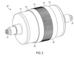
- FIG. 2 is a perspective view of the electrical connector system of FIG. 1 according to various aspects of the invention.
- FIG. 2 illustrates the first electrical connector 111 and the second electrical connector 121 coupled to the coupler 101.
- the coupler 101 may include a first lip 131 and a second lip 141.
- the first lip 131 may extend to cover a first junction between the coupler 101 and the first electrical connector 111.
- the first junction is where the connection interface 113 on the first electrical connector 111 and the first connection interface 107 on the coupler 101 meet.
- the first lip 131 may be used to facilitate improved sealing between the first electrical connector 111 and the coupler 101.
- the second lip 141 may extend to cover a second junction between the coupler 101 and the second electrical connector 121.
- the second junction is where the connection interface 123 on the second electrical connector 121 and the second connection interface 109 on the coupler 101 meet.
- the second lip 141 may similarly be used to facilitate improved sealing between the second electrical connector 121 and the coupler 101.
- FIG. 3 is a perspective view of an electrical connector 311 according to various aspects of the invention.
- the electrical connector 311 is similar to the first electrical connector 111 and like parts are numbered similarly.
- the electrical connector 311 may have a body 320 and a connection interface 313 with one or more linear contact members 315 positioned on the connection interface 313.
- the electrical connector 311 may have one or more conductive elements 317 in electrical communication with the linear contact members 315.
- the one or more conductive elements 317 are depicted as wires, however, other forms of conductive elements may be used interchangeably.
- the linear contact members 315 may be configured to engage with one or more conductive rings on a coupler similar to the coupler 101 depicted in FIG. 1 .
- the linear contact members 315 may be spring probes.
- the one or more linear contact members 315 may be fixed pins.
- connection interface 313 may be formed in any shape or size.
- the connection interface 313 may have a substantially planar shape, a conic shape, an inverted conic shape, a stepped conic shape, an inverted stepped conic shape, a convex shape (outwardly-curving), or a concave shape (inwardly-curving). As depicted in FIG. 3 , the connection interface 313 is formed in a stepped conic shape.
- the electrical connector 311 may have various cross sectional geometries, for example, cylindrical, rectangular, square, or otherwise rotational symmetric. By being rotationally symmetric, the linear contact members 315 do not need to be in rotational alignment with the conductive rings on a coupler, similar to the coupler 101 in FIG. 1 , in order to be in electrical contact or engaged. As depicted in FIG. 3 , the electrical connector 311 has a cylindrical cross sectional geometry.
- the body 320 may include a housing that defines a cavity between the housing and the linear contact members 315.
- the housing may be made out of a high temperature resistant material and/or electrical resistant material.
- the cavity may be an empty space such as a vacuum or may include an insulator disposed within the space.
- the insulator may be a co-fired ceramic insulator such as one formed from alumina-ceramic or other equivalent material.
- An insulator may be disposed between the linear contact members 315 and form the connection interface 313.
- the insulator may form the rings of the stepped conic shape formed in the connection interface 313.
- the insulator may form the connection interface 313 and be disposed within the cavity.
- the insulator may form the body 320 of the electrical connector 311. That is, the insulator may be disposed between the linear contact members 315, form the connection interface 313, be disposed within the cavity, and form the housing of the electrical connector 311.
- the insulator may be a co-fired ceramic insulator such as one formed from alumina-ceramic or other equivalent material.
- the linear contact members 315 are spaced out along the rings formed in the connection interface 313.
- the linear contact members 315 may be similarly spaced out along the circumference of the connection interface 313 formed in a different shape.
- the spacing of the linear contact members 315 may be optimized to reduce noise in the electrical signal or to reduce the chances of a short from occurring.
- the linear contact members 315 may be radially aligned along a central axis of the electrical connector 311.
- FIG. 4 is a perspective view of a coupler for an electrical connector (coupler) 401 according to various aspects of the invention.
- the coupler 401 is similar to the coupler 101 and like parts are numbered similarly.
- the coupler 401 has a first end 403, a second end 405 opposite the first end 403, a first connection interface 407 positioned at the first end 403, a second connection interface 409 positioned at the second end 405, and a body 422.
- the first connection interface 407 and the second connection interface 409 each include a conductive ring set (conductive rings) 416 and 418 are disposed on the respective connection interfaces 407 and 409.
- the conductive ring set 416 on the first connection interface 407 may be electrically connected to the conductive ring set 418 on the second connection interface 409.
- Each ring within the conductive ring set 416 may be individually connected to a corresponding ring within the conductive ring set 418 such that there are an equal number of conductive rings between conductive ring sets 416 and 418.
- Each ring within the conductive ring set 416 is electrically connected to a corresponding companion ring within the conductive ring set 418.
- the conductive ring set 416 may be electrically connected to the conductive ring set 418 by one or more vertical interconnect accesses (VIAs).
- VOAs vertical interconnect accesses
- the conductive ring set 416 may be electrically connected to the conductive ring set 418 by any other form of electrical connection.
- Each ring within the conductive ring sets 416 and 418 may have its own discrete diameter.
- a ring from conductive ring set 416 and its corresponding ring from conductive ring set 418 may have the same diameter.
- a ring from conductive ring set 416 and its corresponding ring from the conductive ring set 418 may have different diameters. The different diameters may correspond to electrical connectors having connection interfaces of unequal size or shape.
- the conductive rings 416 and 418 comprise concentric circles about a common center. In some embodiments, one or more of the conductive rings 416 and 418 may not share a common center with the other rings. In other embodiments, one or more of the conductive rings 416 and 418 may form only partial circles or ellipses.
- connection interfaces 407 and 409 in a a stepped conic shape or an inverted stepped conic shape. As depicted in FIG. 4 , the connection interface 407 is formed in an inverted stepped conic shape. In some embodiments, the connection interfaces 407 and 409 may be the same. In other embodiments, the connection interfaces 407 and 409 may be different.
- the body 422 may include a housing that defines a cavity between the housing and the conductive rings 416 and 418.
- the housing may be made out of a high temperature resistant material and/or electrical resistant material.
- the cavity may be an empty space such as a vacuum or may include an insulator disposed within the space.
- the insulator may be a co-fired ceramic insulator such as one formed from alumina-ceramic or other equivalent material.
- An insulator may be disposed between each ring within the conductive ring sets 416 and 418.
- the insulator may additionally be disposed between the one or more VIAs connecting the conductive ring set 416 to the conductive ring set 418.
- the insulator may form the body 422 of the coupler 401. That is, the insulator may be disposed between each ring within the conductive rings sets 416 and 418, be disposed between the one or more VIAs, be disposed within the cavity, and form the housing of the coupler 401.
- the insulator may be a co-fired ceramic insulator such as one formed from alumina-ceramic or other equivalent material.
- the coupler 401 may include a first lip 431 and a second lip 441.
- the first lip 431 may extend to cover a first junction between the coupler 401 and a first electrical connecter such as the first electrical connector 111 from FIG. 1 .
- the first junction is where a connection interface on the first electrical connector 111 and the first connection interface 407 on the coupler 401 meet.
- the first lip 431 may be used to facilitate improved sealing between the first electrical connector 111 and the coupler 401.
- the second lip 441 extends to cover a second junction between the coupler 401 and a second electrical connector such as the second electrical connector 121 from FIG. 1 .
- the second junction is where a connection interface on the second electrical connector 121 and the second connection interface 409 on the coupler meet.
- the second lip 441 may similarly be used to facilitate improved sealing between the second electrical connector 121 and the coupler 401.
- the first lip 431 and the second lip 441 may further include mating surfaces to removably couple the coupler 401 to a first and second electrical connector. As shown in FIG. 4 , the mating surface is disposed along an interior surface of the first lip 431. In other embodiments, the mating surface may be disposed along an exterior surface of the first lip 431 and the second lip 441. The mating surface may be in the form of screw threading, however, other forms of coupling may be used interchangeably. In some embodiments, the mating surface may further include one or more O-rings to facilitate improved sealing. In other embodiments, a mating surface may not be utilized with the coupler 401.
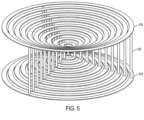
- FIG. 5 is a perspective view of conductive ring sets 516 and 518 according to various aspects of the invention.
- the conductive ring sets 516 and 518 are similar to the conductive ring sets 116 and 118, and like parts are numbered similarly.
- the rings within the conductive ring set 516 are electrically connected to the rings within the conductive ring set 518 by one or more vertical interconnect accesses (VIAs) 519. As shown in FIG. 5 , each ring is connected to a corresponding ring by three (3) VIAs 519. In other embodiments, any number of VIAs 519 may be used to connect corresponding rings between conductive ring sets 516 and 518.
- VIAs vertical interconnect accesses
- the conductive rings within the conductive ring sets 516 and 518 include concentric circles about a common center. In some embodiments, one or more of the conductive rings may not share a common center with the other rings. In other embodiments, one or more of the conductive rings may form only partial circles or ellipses.
- the conductive rings within the conductive rings sets 516 and 518 are arranged to be disposed within a corresponding interface on a coupler similar to the coupler 101 in FIG. 1 .
- the arrangement of the conductive rings, within the conductive ring sets 516 and 518 may be formed to any shape or size.
- the arrangement of the conductive rings, within the conductive ring sets 516 and 518 may be formed to fit within a stepped conic shape or an inverted stepped conic shape. As depicted in FIG. 5 , the rings within the conductive ring sets 516 and 518 are arranged to fit within an inverted stepped conic shape.
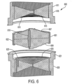
- FIG. 6 is an exploded perspective view of an electrical connector system 600 having a coupler for electrical connectors (coupler) 601, a first electrical connector 611, and a second electrical connector 621 according to various aspects of the invention.
- the coupler 601 has a body 622, a first connection interface 607, and a second connection interface 609.
- One or more linear contact members (linear contact member) 616 are positioned both on the first connection interface 607 and the second connection interface 609.
- the linear contact member 616 provides electrical communication between the first connection interface 607 and the second connection interface 609.
- the one or more linear contact members 616 may be spring probes. In other embodiments, the one or more linear contact members 616 may be fixed pins.
- the first connection interface 607 and the second connection interface 609 may be formed in any shape or size.
- the first connection interface 607 and the second connection interface 609 may have a stepped conic shape or an inverted stepped conic shape. As depicted in FIG. 6 , the first connection interface 607 and the second connection interface 609 is formed in a stepped conic shape.
- the body 622 may include a housing that defines a cavity between the housing and the linear contact member 616.
- the housing may be made out of a high temperature resistant material and/or electrical resistant material.
- the cavity may be an empty space such as a vacuum or may include an insulator disposed within the space.
- the insulator may be a co-fired ceramic insulator such as one formed from alumina-ceramic or other equivalent material.
- An insulator may be disposed between the linear contact member 616 and form the first connection interface 607 and the second connection interface 609.
- the insulator may form the rings of the stepped conic shape formed on the first connection interface 607 and the second connection interface 609.
- the insulator may form the first connection interface 607, the second connection interface 609, and be disposed within the cavity.
- the insulator may form the body 622 of the coupler 601.
- the insulator may be a co-fired ceramic insulator such as one formed from alumina-ceramic or other equivalent material.
- the first electrical connector 611 has a body 618 and connection interface 613 that includes a conductive ring set 615 disposed on the connection interface 613.
- the conductive ring set 615 may include one or more conductive rings within the set.
- the conductive ring set 615 is configured to be engaged by the one or more linear contact members 616.
- Each ring within the conductive ring set 615 is electrically connected to one or more conductive elements.
- the conductive ring set 615 may be electrically connected to the one or more conductive elements by one or more vertical interconnect accesses (VIAs).
- VOAs vertical interconnect accesses
- the conductive ring set 615 may be electrically connected to the one or more conductive elements by any other form of electrical connection.
- the body 618 may include a housing that defines a cavity between the housing 618 and the conductive ring set 615.
- the housing may be made out of a high temperature resistant material and/or electrical resistant material.
- the cavity may be an empty space such as a vacuum or may include an insulator disposed within the space.
- the insulator may be a co-fired ceramic insulator such as one formed from alumina-ceramic or other equivalent material.
- An insulator may be disposed between each ring within the conductive ring set 615.
- the insulator may additionally be disposed between the one or more VIAs connecting the conductive ring set 615 to the one or more conductive elements.
- the insulator may form the body 618 of the first electrical connector 611. That is, the insulator may be disposed between each ring within the conductive rings set 615, be disposed between the one or more VIAs, be disposed within the cavity, and form the housing of the first electrical connector 611.
- the insulator may be a co-fired ceramic insulator such as one formed from alumina-ceramic or other equivalent material.
- the second electrical connector 621 has a body 628 and connection interface 623 that includes a conductive ring set 625 disposed on the connection interface 623.
- the conductive ring set 625 may include one or more conductive rings within the set.
- the conductive ring set 625 is configured to be engaged by the one or more linear contact members 616.
- Each ring within the conductive ring set 625 is electrically connected to one or more conductive elements.
- the conductive ring set 625 may be electrically connected to the one or more conductive elements by one or more vertical interconnect accesses (VIAs).
- VOAs vertical interconnect accesses
- the conductive ring set 625 may be electrically connected to the one or more conductive elements by any other form of electrical connection.
- the body 628 may include a housing that defines a cavity between the housing 628 and the conductive ring set 625.
- the housing may be made out of a high temperature resistant material and/or electrical resistant material.
- the cavity may be an empty space such as a vacuum or may include an insulator disposed within the space.
- the insulator may be a co-fired ceramic insulator such as one formed from alumina-ceramic or other equivalent material.
- An insulator may be disposed between each ring within the conductive ring set 625.
- the insulator may additionally be disposed between the one or more VIAs connecting the conductive ring set 625 to the one or more conductive elements.
- the insulator may form the body 628 of the first electrical connector 621. That is, the insulator may be disposed between each ring within the conductive rings set 625, be disposed between the one or more VIAs, be disposed within the cavity, and form the housing of the first electrical connector 621.
- the insulator may be a co-fired ceramic insulator such as one formed from alumina-ceramic or other equivalent material.
- the first electrical connector 611 and the second electrical connector 621 may be removably coupled to the coupler 601 via a mating surface.
- the mating surface may be in the form of screw threading, however, other forms of coupling may be used interchangeably.
- the mating surface may further comprise one or more O-rings to facilitate improved sealing. In other embodiments, a mating surface may not be utilized within the electrical connector system 600.
- an electrical signal may travel through the conductive elements on the first electrical connector 611 and be received by the conductive ring set 615. From the conductive ring set 615, the electrical signal travels through the linear contact members 616, through the conductive ring set 625, and finally received by conductive elements on the second electrical connector 621.
- the first electrical connector 611 and the second electrical connector 621 may be able to freely rotate relative to the coupler 601. In some embodiments, only the first electrical connector 611 may be able to freely rotate relative to the coupler 601 when the system 600 is coupled together. In other embodiments, neither the first nor the second electrical connectors 611 and 621 may be able to freely rotate relative to the coupler 601 when the system 600 is coupled together.
- first electrical connector 611 and the second electrical connector 621 may be hermetically sealed and connected to an apparatus such as a tool.
- One or both of the first electrical connector 611 and the second electrical connector 621 may be connected to the apparatus through brazing or any other attachment process used to create a hermetic seal.
- both the first electrical connector 611 and the coupler 601 may be similarly connected to the apparatus through brazing or any other attachment process used to create a hermetic seal.
- the electrical connector system 600 may have various cross sectional geometries, for example, cylindrical, rectangular, square, or otherwise rotationally symmetric.
- the linear contact members 616 do not need to be in rotational alignment with the conductive ring sets 615 and 625, at their respective interfaces 613 and 623, in order to be in electrical contact or engaged.
- the linear contact members 616 only need to be in axial alignment with the conductive rings sets 615 and 625 in order to in electrical contact or engaged.
- a user may connect the first electrical connector 611 to the coupler 601, without rotational alignment, by first moving the first electrical connector 611 into axial alignment with the coupler 601, and then moving the first electrical connector 611 axially towards the coupler 601 until the linear contact members 616 engage with the conductive ring set 615.
- a user may similarly connect the second electrical connector 621 to the coupler 601, without rotational alignment, by first moving the second electrical connector 621 into axial alignment with the coupler 601, and then moving the second electrical connector 621 axially towards the coupler 601 until the linear contact member 616 engage with the conductive ring set 625.
- the linear contact members 616 may be in physical contact with the conductive ring set 615. Similarly, the linear contact members 616 may be in physical contact with the conductive ring set 625 when they are engaged. In other embodiments, the linear contact members 616 may only be in electrical communication with the conductive ring sets 615 and 625 when they are engaged despite not being in physical contact.
- the first and second connection interface 607/609 is formed in a stepped conic shape.
- the first connection interface 607 and the second connection interface 609, in system 600 may be formed in any shape or size.
- the first and second connection interface 607 and 609 may have a substantially planar shape, a conic shape, an inverted conic shape, a stepped conic shape, an inverted stepped conic shape, a convex shape (outwardly-curving), or a concave shape (inwardly-curving).
- connection interfaces 613 for the first electrical connector 611 and the connection interface 623 for the second electrical connectors 621 may be formed to complement the shape or size of the first and second connection interface 607 and 609 as described above. For example, if the first and second connection interface 607 and 609 are formed in a conic shape, then the connection interfaces 613 and 623 are formed in an inverted conic shape. As depicted in FIG. 6 , the connection interfaces 613 and 623 for the first and the second electrical connectors 611 and 621 are formed in an inverted stepped conic shape. In some embodiments, the connection interfaces 607 and 609 may be the same. In other embodiments, the connection interfaces 607 and 609 may be different.
Landscapes
- Details Of Connecting Devices For Male And Female Coupling (AREA)
- Connector Housings Or Holding Contact Members (AREA)
Description
- This specification relates to an electrical connector assembly.
- Electrical connector assemblies are used in high temperature and high pressure environments. Current electrical connector assemblies that are used in such environments usually require the use of O-rings and a central cartridge to provide high temperature and pressure resistance. This configuration presents a drawback as O-rings require frequent inspection and maintenance in order to reduce the potential for breakdown and failure of the electrical connector. The central cartridge includes other components that also require additional inspection and maintenance to ensure continued reliability.
- Accordingly, there is a need for a rotatable electrical connector assembly made up of fewer components that provides greater reliability and a high temperature and pressure interface.
-
US3,060,417 discloses a condition responsive network insensitive to electrical leakage. -
US2006/134933 discloses an electrical connector assembly. - Aspects of the invention are recited in the independent claims and preferred features are recited in the dependent claims.
- A coupler for electrical connectors is disclosed. The coupler includes a body having a first end and a second end opposite the first end. The coupler further includes a first connection interface positioned at the first end of the body, the first connection interface having a first set of conductive rings. The coupler further includes a second connection interface positioned at the second end of the body, the second connection interface having a second set of conductive rings electrically connected to the first set of conductive rings, wherein the first connection interface and the second connection interface are formed in at least one of a stepped conic shape or an inverted stepped conic shape, wherein the rings of the first set of conductive rings and of the second set of conductive rings are configured to interface with linear contact members of a connection interface of connectors.
- An electrical connector is disclosed. The electrical connector includes a connection interface being formed in at least one of an inverted stepped conic shape or a stepped conic shape, the connection interface being configured to interface with a coupler for an electrical connector. The electrical connector further includes one or more linear contact members positioned on the connection interface, each linear contact member being configured to contact a conductive ring on the coupler.
- An electrical connector system is disclosed, comprising both the coupler and the electrical connector.
- The features and advantages of the embodiments of the present disclosure will become more apparent from the detailed description set forth below when taken in conjunction with the drawings. Naturally, the drawings and their associated descriptions illustrate example arrangements within the scope of the claims and do not limit the scope of the claims. Reference numbers are reused throughout the drawings to indicate correspondence between referenced elements.
-
FIG. 1 is an exploded perspective view of an electrical connector system according to various aspects of the invention. -
FIG. 2 is a perspective view of the electrical connector system ofFIG. 1 according to various aspects of the invention. -
FIG. 3 is a perspective view of an electrical connector according to various aspects of the invention. -
FIG. 4 is a perspective view of a coupler for electrical connectors according to various aspects of the invention. -
FIG. 5 is a perspective view of conductive rings according to various aspects of the invention. -
FIG. 6 is an exploded perspective view of an electrical connector system according to various aspects of the invention. - In the following detailed description, numerous specific details are set forth to provide an understanding of the present disclosure. It will be apparent, however, to one of ordinary skill in the art that elements of the present disclosure may be practiced without some of these specific details. In other instances, well-known structures and techniques have not been shown in detail to avoid unnecessarily obscuring the present disclosure.
-
FIG. 1 is an exploded perspective view of anelectrical connector system 100 having a coupler for electrical connectors (coupler) 101, a firstelectrical connector 111, and a secondelectrical connector 121 according to various aspects of the invention. - The
coupler 101 has afirst end 103, asecond end 105 opposite thefirst end 103, afirst connection interface 107 positioned at thefirst end 103, and asecond connection interface 109 positioned at thesecond end 105. Thefirst connection interface 107 includes a firstconductive ring set 116 disposed on thefirst connection interface 107. Thesecond connection interface 109 includes a secondconductive ring set 118 disposed on thesecond connection interface 109. The first conductive ring set 116 and the secondconductive ring set 118 may each include one or more conductive rings within their respective set. - The first conductive ring set 116 on the
first connection interface 107 may be electrically connected to the secondconductive ring set 118 on thesecond connection interface 109. Each ring within the firstconductive ring set 116 may be individually connected to a corresponding ring within the second conductive ring set 118 such that the firstconductive ring set 116 has an equal number of conductive rings as the second conductive ring set 118. - The first
electrical connector 111 has aconnection interface 113 with one or morelinear contact members 115 positioned on theconnection interface 113. The firstelectrical connector 111 may also have one or moreconductive elements 117 in electrical communication with the one or morelinear contact members 115. - The second
electrical connector 121 may similarly have aconnection interface 123 with one or morelinear contact members 125 positioned on theconnection interface 123. The secondelectrical connector 121 may also have one or moreconductive elements 127 in electrical communication with the one or morelinear contact members 125. In some embodiments, thelinear contact members linear contact members - The first
electrical connector 111 and the secondelectrical connector 121 may be removably coupled to thecoupler 101 via a mating surface. The mating surface may be in the form of screw threading, however, other forms of coupling may be used interchangeably. In some embodiments, the mating surface may further comprise one or more O-rings to facilitate improved sealing. In other embodiments, a mating surface may not be utilized within theelectrical connector system 100. - When the first
electrical connector 111 is coupled to thecoupler 101, as depicted inFIG. 2 , thelinear contact members 115 are in electrical contact with the firstconductive ring set 116 on thefirst connection interface 107. Similarly, when the secondelectrical connector 121 is coupled to thecoupler 101, also depicted inFIG. 2 , thelinear contact members 125 are in electrical contact with the second conductive ring set 118 on thesecond connection interface 109. - When the first
electrical connector 111, thecoupler 101, and the secondelectrical connector 121 of thesystem 100 are coupled together, an electrical signal may travel through theconductive elements 117 on the firstelectrical connector 111 and be received by thelinear contact members 115. From thelinear contact members 115, the electrical signal travels through the firstconductive ring set 116 at thefirst connection interface 107, through the secondconductive ring set 118 at thesecond connection interface 109, through thelinear contact members 125 positioned on theconnection interface 123, and finally received byconductive elements 127 on the secondelectrical connector 121. - When the
system 100 is coupled together, the firstelectrical connector 111 and the secondelectrical connector 121 may be able to freely rotate relative to thecoupler 101. In some embodiments, only the firstelectrical connector 111 may be able to freely rotate relative to thecoupler 101 when thesystem 100 is coupled together. In other embodiments, neither the first nor the secondelectrical connectors coupler 101 when thesystem 100 is coupled together. - In some embodiments, one or both of the first
electrical connector 111 and the secondelectrical connector 121 may be connected to an apparatus such as a tool and contained within a hermetic enclosure. In some embodiments, thecoupler 101 may form a bulkhead seal cap by being connected to a bulkhead. Thecoupler 101 may be connected to a mating surface of the bulkhead through brazing or any other attachment process used to create a hermetic seal. - The
electrical connector system 100 may have various cross sectional geometries, for example, cylindrical, rectangular, square, or otherwise rotationally symmetric. By being rotationally symmetric, thelinear contact members conductive ring sets respective interfaces linear contact members - A user may connect the first
electrical connector 111 to thecoupler 101, without rotational alignment, by first moving the firstelectrical connector 111 into axial alignment with thecoupler 101, and then moving the firstelectrical connector 111 axially towards thecoupler 101 until thelinear contact members 115 engage with the first conductive ring set 116. A user may similarly connect the secondelectrical connector 121 to thecoupler 101, without rotational alignment, by first moving the secondelectrical connector 121 into axial alignment with thecoupler 101, and then moving the secondelectrical connector 121 axially towards thecoupler 101 until thelinear contact members 125 engage with the second conductive ring set 118. - The
linear contact members 115 may be in physical contact with the first conductive ring set 116 on thecoupler 101 when they are engaged. Similarly, thelinear contact members 125 may be in physical contact with the second conductive ring set 118 on thecoupler 101 when they are engaged. In other embodiments, thelinear contact members coupler 101 when they are engaged despite not being in physical contact. - In some embodiments, the
coupler 101 and the secondelectrical connector 121 may be integrated into a single combined component. The combined component may have thefirst end 103, thesecond end 105 opposite thefirst end 103, thefirst connection interface 107 positioned at thefirst end 103, and the one or moreconductive elements 127 positioned at thesecond end 105. Thefirst connection interface 107 may include the first conductive ring set 116 in electrical communication with the one or moreconductive elements 127. - When the first
electrical connector 111 and the combined component, as described above, are coupled together, an electrical signal may travel through theconductive elements 117 on the firstelectrical connector 111 and be received by thelinear contact members 115. From thelinear contact members 115, the electrical signal travels through the first conductive ring set 116 at thefirst connection interface 107, and finally received by the one or moreconductive elements 127 positioned at thesecond end 103. - As depicted in
FIG. 1 , the first andsecond connection interface - Both the
connection interface 113 for the firstelectrical connector 111 and theconnection interface 123 for the secondelectrical connectors 121 are formed to complement the shape or size of the first and second connection interfaces 107 and 109 as described above. For example, if the first and second connection interfaces 107 and 109 are formed in an inverted conic shape, then the connection interfaces 113 and 123 are formed in a conic shape. As depicted inFIG. 1 , the connection interfaces 113 and 123 for the first and the secondelectrical connectors -
FIG. 2 is a perspective view of the electrical connector system ofFIG. 1 according to various aspects of the invention.FIG. 2 illustrates the firstelectrical connector 111 and the secondelectrical connector 121 coupled to thecoupler 101. - The
coupler 101 may include afirst lip 131 and asecond lip 141. Thefirst lip 131 may extend to cover a first junction between thecoupler 101 and the firstelectrical connector 111. The first junction is where theconnection interface 113 on the firstelectrical connector 111 and thefirst connection interface 107 on thecoupler 101 meet. Thefirst lip 131 may be used to facilitate improved sealing between the firstelectrical connector 111 and thecoupler 101. Similarly, thesecond lip 141 may extend to cover a second junction between thecoupler 101 and the secondelectrical connector 121. The second junction is where theconnection interface 123 on the secondelectrical connector 121 and thesecond connection interface 109 on thecoupler 101 meet. Thesecond lip 141 may similarly be used to facilitate improved sealing between the secondelectrical connector 121 and thecoupler 101. -
FIG. 3 is a perspective view of anelectrical connector 311 according to various aspects of the invention. Theelectrical connector 311 is similar to the firstelectrical connector 111 and like parts are numbered similarly. - The
electrical connector 311 may have abody 320 and aconnection interface 313 with one or morelinear contact members 315 positioned on theconnection interface 313. Theelectrical connector 311 may have one or moreconductive elements 317 in electrical communication with thelinear contact members 315. InFIG. 3 , the one or moreconductive elements 317 are depicted as wires, however, other forms of conductive elements may be used interchangeably. - The
linear contact members 315 may be configured to engage with one or more conductive rings on a coupler similar to thecoupler 101 depicted inFIG. 1 . In some embodiments, thelinear contact members 315 may be spring probes. In other embodiments, the one or morelinear contact members 315 may be fixed pins. - The
connection interface 313 may be formed in any shape or size. Theconnection interface 313 may have a substantially planar shape, a conic shape, an inverted conic shape, a stepped conic shape, an inverted stepped conic shape, a convex shape (outwardly-curving), or a concave shape (inwardly-curving). As depicted inFIG. 3 , theconnection interface 313 is formed in a stepped conic shape. - The
electrical connector 311 may have various cross sectional geometries, for example, cylindrical, rectangular, square, or otherwise rotational symmetric. By being rotationally symmetric, thelinear contact members 315 do not need to be in rotational alignment with the conductive rings on a coupler, similar to thecoupler 101 inFIG. 1 , in order to be in electrical contact or engaged. As depicted inFIG. 3 , theelectrical connector 311 has a cylindrical cross sectional geometry. - In some embodiments, the
body 320 may include a housing that defines a cavity between the housing and thelinear contact members 315. The housing may be made out of a high temperature resistant material and/or electrical resistant material. The cavity may be an empty space such as a vacuum or may include an insulator disposed within the space. The insulator may be a co-fired ceramic insulator such as one formed from alumina-ceramic or other equivalent material. - An insulator may be disposed between the
linear contact members 315 and form theconnection interface 313. InFIG. 3 , the insulator may form the rings of the stepped conic shape formed in theconnection interface 313. In some embodiments, the insulator may form theconnection interface 313 and be disposed within the cavity. In other embodiments, the insulator may form thebody 320 of theelectrical connector 311. That is, the insulator may be disposed between thelinear contact members 315, form theconnection interface 313, be disposed within the cavity, and form the housing of theelectrical connector 311. The insulator may be a co-fired ceramic insulator such as one formed from alumina-ceramic or other equivalent material. - As depicted in
FIG. 3 , thelinear contact members 315 are spaced out along the rings formed in theconnection interface 313. In some embodiments, thelinear contact members 315 may be similarly spaced out along the circumference of theconnection interface 313 formed in a different shape. The spacing of thelinear contact members 315 may be optimized to reduce noise in the electrical signal or to reduce the chances of a short from occurring. In other embodiments, thelinear contact members 315 may be radially aligned along a central axis of theelectrical connector 311. -
FIG. 4 is a perspective view of a coupler for an electrical connector (coupler) 401 according to various aspects of the invention. Thecoupler 401 is similar to thecoupler 101 and like parts are numbered similarly. - The
coupler 401 has afirst end 403, asecond end 405 opposite thefirst end 403, afirst connection interface 407 positioned at thefirst end 403, asecond connection interface 409 positioned at thesecond end 405, and abody 422. Thefirst connection interface 407 and thesecond connection interface 409 each include a conductive ring set (conductive rings) 416 and 418 are disposed on therespective connection interfaces - The conductive ring set 416 on the
first connection interface 407 may be electrically connected to the conductive ring set 418 on thesecond connection interface 409. Each ring within the conductive ring set 416 may be individually connected to a corresponding ring within the conductive ring set 418 such that there are an equal number of conductive rings between conductive ring sets 416 and 418. - Each ring within the conductive ring set 416 is electrically connected to a corresponding companion ring within the conductive ring set 418. In some embodiments, the conductive ring set 416 may be electrically connected to the conductive ring set 418 by one or more vertical interconnect accesses (VIAs). In other embodiments, the conductive ring set 416 may be electrically connected to the conductive ring set 418 by any other form of electrical connection.
- Each ring within the conductive ring sets 416 and 418 may have its own discrete diameter. In some embodiments, a ring from conductive ring set 416 and its corresponding ring from conductive ring set 418 may have the same diameter. In other embodiments, a ring from conductive ring set 416 and its corresponding ring from the conductive ring set 418 may have different diameters. The different diameters may correspond to electrical connectors having connection interfaces of unequal size or shape.
- As shown in
FIG. 4 , theconductive rings conductive rings conductive rings - The connection interfaces 407 and 409 in a a stepped conic shape or an inverted stepped conic shape. As depicted in
FIG. 4 , theconnection interface 407 is formed in an inverted stepped conic shape. In some embodiments, the connection interfaces 407 and 409 may be the same. In other embodiments, the connection interfaces 407 and 409 may be different. - In some embodiments, the
body 422 may include a housing that defines a cavity between the housing and theconductive rings - An insulator may be disposed between each ring within the conductive ring sets 416 and 418. In some embodiments, the insulator may additionally be disposed between the one or more VIAs connecting the conductive ring set 416 to the conductive ring set 418. In other embodiments, the insulator may form the
body 422 of thecoupler 401. That is, the insulator may be disposed between each ring within the conductive rings sets 416 and 418, be disposed between the one or more VIAs, be disposed within the cavity, and form the housing of thecoupler 401. The insulator may be a co-fired ceramic insulator such as one formed from alumina-ceramic or other equivalent material. - The
coupler 401 may include afirst lip 431 and asecond lip 441. Thefirst lip 431 may extend to cover a first junction between thecoupler 401 and a first electrical connecter such as the firstelectrical connector 111 fromFIG. 1 . The first junction is where a connection interface on the firstelectrical connector 111 and thefirst connection interface 407 on thecoupler 401 meet. Thefirst lip 431 may be used to facilitate improved sealing between the firstelectrical connector 111 and thecoupler 401. Similarly, thesecond lip 441 extends to cover a second junction between thecoupler 401 and a second electrical connector such as the secondelectrical connector 121 fromFIG. 1 . The second junction is where a connection interface on the secondelectrical connector 121 and thesecond connection interface 409 on the coupler meet. Thesecond lip 441 may similarly be used to facilitate improved sealing between the secondelectrical connector 121 and thecoupler 401. - The
first lip 431 and thesecond lip 441 may further include mating surfaces to removably couple thecoupler 401 to a first and second electrical connector. As shown inFIG. 4 , the mating surface is disposed along an interior surface of thefirst lip 431. In other embodiments, the mating surface may be disposed along an exterior surface of thefirst lip 431 and thesecond lip 441. The mating surface may be in the form of screw threading, however, other forms of coupling may be used interchangeably. In some embodiments, the mating surface may further include one or more O-rings to facilitate improved sealing. In other embodiments, a mating surface may not be utilized with thecoupler 401. -
FIG. 5 is a perspective view of conductive ring sets 516 and 518 according to various aspects of the invention. The conductive ring sets 516 and 518 are similar to the conductive ring sets 116 and 118, and like parts are numbered similarly. - The rings within the conductive ring set 516 are electrically connected to the rings within the conductive ring set 518 by one or more vertical interconnect accesses (VIAs) 519. As shown in
FIG. 5 , each ring is connected to a corresponding ring by three (3) VIAs 519. In other embodiments, any number of VIAs 519 may be used to connect corresponding rings between conductive ring sets 516 and 518. - The conductive rings within the conductive ring sets 516 and 518 include concentric circles about a common center. In some embodiments, one or more of the conductive rings may not share a common center with the other rings. In other embodiments, one or more of the conductive rings may form only partial circles or ellipses.
- The conductive rings within the conductive rings sets 516 and 518 are arranged to be disposed within a corresponding interface on a coupler similar to the
coupler 101 inFIG. 1 . The arrangement of the conductive rings, within the conductive ring sets 516 and 518, may be formed to any shape or size. The arrangement of the conductive rings, within the conductive ring sets 516 and 518, may be formed to fit within a stepped conic shape or an inverted stepped conic shape. As depicted inFIG. 5 , the rings within the conductive ring sets 516 and 518 are arranged to fit within an inverted stepped conic shape. -
FIG. 6 is an exploded perspective view of anelectrical connector system 600 having a coupler for electrical connectors (coupler) 601, a firstelectrical connector 611, and a secondelectrical connector 621 according to various aspects of the invention. - The
coupler 601 has abody 622, afirst connection interface 607, and asecond connection interface 609. One or more linear contact members (linear contact member) 616 are positioned both on thefirst connection interface 607 and thesecond connection interface 609. Thelinear contact member 616 provides electrical communication between thefirst connection interface 607 and thesecond connection interface 609. In some embodiments, the one or morelinear contact members 616 may be spring probes. In other embodiments, the one or morelinear contact members 616 may be fixed pins. - The
first connection interface 607 and thesecond connection interface 609 may be formed in any shape or size. Thefirst connection interface 607 and thesecond connection interface 609 may have a stepped conic shape or an inverted stepped conic shape. As depicted inFIG. 6 , thefirst connection interface 607 and thesecond connection interface 609 is formed in a stepped conic shape. - In some embodiments, the
body 622 may include a housing that defines a cavity between the housing and thelinear contact member 616. The housing may be made out of a high temperature resistant material and/or electrical resistant material. The cavity may be an empty space such as a vacuum or may include an insulator disposed within the space. The insulator may be a co-fired ceramic insulator such as one formed from alumina-ceramic or other equivalent material. - An insulator may be disposed between the
linear contact member 616 and form thefirst connection interface 607 and thesecond connection interface 609. InFIG. 6 , the insulator may form the rings of the stepped conic shape formed on thefirst connection interface 607 and thesecond connection interface 609. In some embodiments, the insulator may form thefirst connection interface 607, thesecond connection interface 609, and be disposed within the cavity. In other embodiments, the insulator may form thebody 622 of thecoupler 601. The insulator may be a co-fired ceramic insulator such as one formed from alumina-ceramic or other equivalent material. - The first
electrical connector 611 has abody 618 andconnection interface 613 that includes a conductive ring set 615 disposed on theconnection interface 613. The conductive ring set 615 may include one or more conductive rings within the set. In some embodiments, the conductive ring set 615 is configured to be engaged by the one or morelinear contact members 616. Each ring within the conductive ring set 615 is electrically connected to one or more conductive elements. In some embodiments, the conductive ring set 615 may be electrically connected to the one or more conductive elements by one or more vertical interconnect accesses (VIAs). In other embodiments, the conductive ring set 615 may be electrically connected to the one or more conductive elements by any other form of electrical connection. - In some embodiments, the
body 618 may include a housing that defines a cavity between thehousing 618 and the conductive ring set 615. The housing may be made out of a high temperature resistant material and/or electrical resistant material. The cavity may be an empty space such as a vacuum or may include an insulator disposed within the space. The insulator may be a co-fired ceramic insulator such as one formed from alumina-ceramic or other equivalent material. - An insulator may be disposed between each ring within the conductive ring set 615. In some embodiments, the insulator may additionally be disposed between the one or more VIAs connecting the conductive ring set 615 to the one or more conductive elements. In other embodiments, the insulator may form the
body 618 of the firstelectrical connector 611. That is, the insulator may be disposed between each ring within the conductive rings set 615, be disposed between the one or more VIAs, be disposed within the cavity, and form the housing of the firstelectrical connector 611. The insulator may be a co-fired ceramic insulator such as one formed from alumina-ceramic or other equivalent material. - Similarly, the second
electrical connector 621 has abody 628 andconnection interface 623 that includes a conductive ring set 625 disposed on theconnection interface 623. The conductive ring set 625 may include one or more conductive rings within the set. In some embodiments, the conductive ring set 625 is configured to be engaged by the one or morelinear contact members 616. Each ring within the conductive ring set 625 is electrically connected to one or more conductive elements. In some embodiments, the conductive ring set 625 may be electrically connected to the one or more conductive elements by one or more vertical interconnect accesses (VIAs). In other embodiments, the conductive ring set 625 may be electrically connected to the one or more conductive elements by any other form of electrical connection. - In some embodiments, the
body 628 may include a housing that defines a cavity between thehousing 628 and the conductive ring set 625. The housing may be made out of a high temperature resistant material and/or electrical resistant material. The cavity may be an empty space such as a vacuum or may include an insulator disposed within the space. The insulator may be a co-fired ceramic insulator such as one formed from alumina-ceramic or other equivalent material. - An insulator may be disposed between each ring within the conductive ring set 625. In some embodiments, the insulator may additionally be disposed between the one or more VIAs connecting the conductive ring set 625 to the one or more conductive elements. In other embodiments, the insulator may form the
body 628 of the firstelectrical connector 621. That is, the insulator may be disposed between each ring within the conductive rings set 625, be disposed between the one or more VIAs, be disposed within the cavity, and form the housing of the firstelectrical connector 621. The insulator may be a co-fired ceramic insulator such as one formed from alumina-ceramic or other equivalent material. - The first
electrical connector 611 and the secondelectrical connector 621 may be removably coupled to thecoupler 601 via a mating surface. The mating surface may be in the form of screw threading, however, other forms of coupling may be used interchangeably. In some embodiments, the mating surface may further comprise one or more O-rings to facilitate improved sealing. In other embodiments, a mating surface may not be utilized within theelectrical connector system 600. - When the first
electrical connector 611 is coupled to thecoupler 601 thelinear contact members 616 are in electrical contact with the conductive ring set 615. Similarly, when the secondelectrical connector 621 is coupled to thecoupler 601 thelinear contact members 616 are in electrical contact with the conductive ring set 625. - When the first
electrical connector 611, thecoupler 601, and the secondelectrical connector 621 of thesystem 600 are coupled together, an electrical signal may travel through the conductive elements on the firstelectrical connector 611 and be received by the conductive ring set 615. From the conductive ring set 615, the electrical signal travels through thelinear contact members 616, through the conductive ring set 625, and finally received by conductive elements on the secondelectrical connector 621. - When the
system 600 is coupled together, the firstelectrical connector 611 and the secondelectrical connector 621 may be able to freely rotate relative to thecoupler 601. In some embodiments, only the firstelectrical connector 611 may be able to freely rotate relative to thecoupler 601 when thesystem 600 is coupled together. In other embodiments, neither the first nor the secondelectrical connectors coupler 601 when thesystem 600 is coupled together. - In some embodiments, one or both of the first
electrical connector 611 and the secondelectrical connector 621 may be hermetically sealed and connected to an apparatus such as a tool. One or both of the firstelectrical connector 611 and the secondelectrical connector 621 may be connected to the apparatus through brazing or any other attachment process used to create a hermetic seal. In other embodiments, both the firstelectrical connector 611 and thecoupler 601 may be similarly connected to the apparatus through brazing or any other attachment process used to create a hermetic seal. - The
electrical connector system 600 may have various cross sectional geometries, for example, cylindrical, rectangular, square, or otherwise rotationally symmetric. By being rotationally symmetric, thelinear contact members 616 do not need to be in rotational alignment with the conductive ring sets 615 and 625, at theirrespective interfaces linear contact members 616 only need to be in axial alignment with the conductive rings sets 615 and 625 in order to in electrical contact or engaged. - A user may connect the first
electrical connector 611 to thecoupler 601, without rotational alignment, by first moving the firstelectrical connector 611 into axial alignment with thecoupler 601, and then moving the firstelectrical connector 611 axially towards thecoupler 601 until thelinear contact members 616 engage with the conductive ring set 615. A user may similarly connect the secondelectrical connector 621 to thecoupler 601, without rotational alignment, by first moving the secondelectrical connector 621 into axial alignment with thecoupler 601, and then moving the secondelectrical connector 621 axially towards thecoupler 601 until thelinear contact member 616 engage with the conductive ring set 625. - The
linear contact members 616 may be in physical contact with the conductive ring set 615. Similarly, thelinear contact members 616 may be in physical contact with the conductive ring set 625 when they are engaged. In other embodiments, thelinear contact members 616 may only be in electrical communication with the conductive ring sets 615 and 625 when they are engaged despite not being in physical contact. - As depicted in
FIG. 6 , the first andsecond connection interface 607/609 is formed in a stepped conic shape. However, thefirst connection interface 607 and thesecond connection interface 609, insystem 600, may be formed in any shape or size. The first andsecond connection interface - The connection interfaces 613 for the first
electrical connector 611 and theconnection interface 623 for the secondelectrical connectors 621 may be formed to complement the shape or size of the first andsecond connection interface second connection interface FIG. 6 , the connection interfaces 613 and 623 for the first and the secondelectrical connectors - The foregoing description of the disclosed example embodiments is provided to enable any person of ordinary skill in the art to make or use the present invention.
Claims (11)
- A coupler (101, 401, 611, 621) for an electrical connector (111, 121, 311, 601), comprising:a body (422) having a first end (103, 403) and a second end (105, 405) opposite the first end;a first connection interface (107, 407, 613, 623) positioned at the first end of the body, the first connection interface (107, 407, 613, 623) having a first set of conductive rings (116, 118, 416, 418, 615, 625); anda second connection interface (109, 409) positioned at the second end (105, 405) of the body, the second connection interface (109, 409) having a second set of conductive rings (118, 418) electrically connected to the first set of conductive rings (116, 416), wherein the rings of the first set of conductive rings and of the second set of conductive rings are configured to interface with linear contact members of a connection interface (113, 123, 313, 607, 609) of connectors (111, 121, 311, 601), the coupler being characterized in thatthe first connection interface (107, 407, 613, 623) and the second connection interface (109, 409) are formed in at least one of a stepped conic shape or an inverted stepped conic shape.
- The coupler of claim 1, wherein the first set of conductive rings (116, 416) and the second set of conductive rings (118, 418) are connected by one or more vertical interconnect accesses (519), VIAs, optionally further comprising an insulator between a portion of the one or more VIAs, the first set of conductive rings (116, 416) or the second set of conductive rings (118, 418).
- The coupler of claim 1, wherein the body (422) is configured to be connected to a mating surface by a hermetic sealing process.
- The coupler of claim 1, wherein a diameter of an outer ring of the first set of conductive rings (116, 416) and a diameter of an outer ring of the second set of conductive rings is greater than a diameter of an inner ring of the first set of conductive rings (116, 416) and a diameter of an inner ring of the second set of conductive rings (118, 418).
- An electrical connector (111, 121, 311, 601), comprising:a connection interface (113, 123, 313, 607, 609), the connection interface (113, 123, 313, 607, 609) being formed in at least one of an inverted stepped conic shape or a stepped conic shape, the connection interface being configured to interface with a first connection interface (107, 407, 613, 623) of a coupler (101, 401, 611, 621) for an electrical connector, the first connection interface (107, 407, 613, 623) being formed in at least one of a stepped conic shape or an inverted stepped conic shape; andone or more linear contact members (115, 125, 315, 616) positioned on the connection interface (113, 123, 313, 607, 609), each linear contact member being configured to contact a conductive ring (116, 118, 416, 418, 615, 625) on the coupler (101, 401, 611, 621).
- The electrical connector of claim 5, wherein the one or more linear contact members (115, 125, 315, 616) include a spring probe or a fixed pin, or further comprising an insulator between the one or more linear contact members (115, 125, 315, 616).
- An electrical connector system, comprising:a coupler (101, 401, 611, 621) according to claim 1; andan electrical connector (111, 121, 311, 601) according to claim 5.
- The electrical connector system of claim 7, further comprising:
a second electrical connector (121, 311), the second electrical connector having:a connection interface (123, 313) configured to interface with the second connection interface (109, 409) of the coupler (101, 401), andat least one linear contact member (125, 315) positioned on the connection interface, the at least one linear contact member (125, 315) being configured to contact a conductive ring (118, 418) of the second connection interface (109, 409). - The electrical connector system of claim 8, wherein the connection interface (107, 407) at the first end (103, 403) and the second connection interface (109, 409) at the second end (105, 405) are connected by one or more vertical interconnect accesses, VIAs.
- The electrical connector system of claim 7, wherein the at least one linear contact members (115, 125, 315, 616) include a spring probe or a fixed pin.
- The electrical connector system of claim 9, further comprising an insulator between a portion of the one or more VIAs, the one or more conductive rings (116, 118, 416, 418, 615, 625) on the first end (103, 403) of the connection interface, or the at least one linear contact member (115, 125, 315, 616).
Applications Claiming Priority (2)
| Application Number | Priority Date | Filing Date | Title |
|---|---|---|---|
| US201762509658P | 2017-05-22 | 2017-05-22 | |
| PCT/US2018/032442 WO2018217480A1 (en) | 2017-05-22 | 2018-05-11 | Dry mate rotatable connector |
Publications (3)
| Publication Number | Publication Date |
|---|---|
| EP3631908A1 EP3631908A1 (en) | 2020-04-08 |
| EP3631908A4 EP3631908A4 (en) | 2021-02-24 |
| EP3631908B1 true EP3631908B1 (en) | 2024-05-29 |
Family
ID=64395815
Family Applications (1)
| Application Number | Title | Priority Date | Filing Date |
|---|---|---|---|
| EP18806795.3A Active EP3631908B1 (en) | 2017-05-22 | 2018-05-11 | Dry mate rotatable connector |
Country Status (5)
| Country | Link |
|---|---|
| US (1) | US11101598B2 (en) |
| EP (1) | EP3631908B1 (en) |
| JP (1) | JP7101764B2 (en) |
| CN (1) | CN110945723B (en) |
| WO (1) | WO2018217480A1 (en) |
Families Citing this family (1)
| Publication number | Priority date | Publication date | Assignee | Title |
|---|---|---|---|---|
| IT202100005204A1 (en) * | 2021-03-05 | 2022-09-05 | Prysmian Spa | CABLE CONNECTION SYSTEM FOR ELECTRIC POWER SUPPLY |
Family Cites Families (16)
| Publication number | Priority date | Publication date | Assignee | Title |
|---|---|---|---|---|
| US3060417A (en) | 1959-01-20 | 1962-10-23 | Specialties Dev Corp | Condition responsive network insensitive to electrical leakage |
| US4421371A (en) * | 1980-07-15 | 1983-12-20 | The United States Of America As Represented By The Administrator Of The National Aeronautics And Space Administration | Electrical self-aligning connector |
| SE442468B (en) * | 1983-04-14 | 1985-12-23 | Stratos Ab | COUPLING |
| US4773866A (en) * | 1986-09-26 | 1988-09-27 | Basques Eric O | Rotatable electrical connector |
| CA2176047C (en) * | 1995-05-22 | 2000-04-11 | Mohi Sobhani | Spring loaded rotary connector |
| US6190616B1 (en) | 1997-09-11 | 2001-02-20 | Molecular Dynamics, Inc. | Capillary valve, connector, and router |
| AU2001210309A1 (en) | 2000-10-24 | 2002-05-06 | Ormazabal Y Cia., S.A. | Cell union assembly for electric switchgear |
| JP2005267943A (en) * | 2004-03-17 | 2005-09-29 | Jamco Corp | Audio plug |
| JP2006004802A (en) * | 2004-06-18 | 2006-01-05 | Yaskawa Electric Corp | Small rotating connector |
| TWI240467B (en) * | 2004-12-21 | 2005-09-21 | Yue-Yun Huang | Infinite rotary electric connector and electric facility with said electric connector |
| KR101312429B1 (en) * | 2010-11-12 | 2013-09-27 | 주식회사 엘지화학 | Coupling socket and assembly for cable-type secandary battery |
| US20130059474A1 (en) * | 2011-09-07 | 2013-03-07 | David R. Hall | Conical Inductive Coupler |
| CN103066442B (en) * | 2012-11-30 | 2015-10-21 | 重庆富士特电控有限公司 | The plugs and sockets of employing face contact |
| EP2853680A1 (en) * | 2013-09-30 | 2015-04-01 | Siemens Aktiengesellschaft | Flushing arrangement |
| CN204333352U (en) * | 2014-09-11 | 2015-05-13 | 得意精密电子(苏州)有限公司 | Socket connector |
| US9650848B2 (en) * | 2015-05-01 | 2017-05-16 | Sabritec | Flexible contacts for use in oil and gas applications |
-
2018
- 2018-05-11 CN CN201880049307.7A patent/CN110945723B/en active Active
- 2018-05-11 US US16/613,515 patent/US11101598B2/en active Active
- 2018-05-11 EP EP18806795.3A patent/EP3631908B1/en active Active
- 2018-05-11 WO PCT/US2018/032442 patent/WO2018217480A1/en not_active Ceased
- 2018-05-11 JP JP2020516377A patent/JP7101764B2/en active Active
Also Published As
| Publication number | Publication date |
|---|---|
| CN110945723B (en) | 2023-06-20 |
| JP7101764B2 (en) | 2022-07-15 |
| WO2018217480A1 (en) | 2018-11-29 |
| CN110945723A (en) | 2020-03-31 |
| EP3631908A1 (en) | 2020-04-08 |
| EP3631908A4 (en) | 2021-02-24 |
| JP2020521311A (en) | 2020-07-16 |
| US11101598B2 (en) | 2021-08-24 |
| US20200076119A1 (en) | 2020-03-05 |
Similar Documents
| Publication | Publication Date | Title |
|---|---|---|
| JP3683864B2 (en) | Electrical connector with mixed grounded and ungrounded contacts | |
| US3681739A (en) | Sealed coaxial cable connector | |
| CN104040804B (en) | Rf connector | |
| KR101754140B1 (en) | Airtight coaxial connector | |
| US20110130048A1 (en) | Plug connector and plug connector set | |
| KR101842580B1 (en) | Low passive intermodulation coaxial connector test interface | |
| US9810568B2 (en) | Use of resilient seals for high temperature and/or high pressure sealing in a guided wave radar level measurement device | |
| EP2942844A1 (en) | Connector structure | |
| US10153600B2 (en) | Angled coaxial connectors for receiving electrical conductor pins having different sizes | |
| EP2880718A1 (en) | Electrical connector system with replaceable sealing element | |
| CN218887732U (en) | Coaxial adapter housing, coaxial adapter and coaxial connector assembly | |
| US11101598B2 (en) | Dry mate rotatable connector | |
| CN214957487U (en) | Electrical connector | |
| JP2016518686A (en) | Plug connector | |
| KR20170061046A (en) | Wrong mating prevention structure of the connector | |
| CN114450859B (en) | Low passive intermodulation connector system | |
| JPH0156507B2 (en) | ||
| US7114956B2 (en) | Isolated BNC connector with replaceable bayonet shell | |
| CN109449699A (en) | A kind of RF coaxial adapters | |
| TWI807268B (en) | Check connector | |
| US20140059854A1 (en) | Crushable Connector Interface | |
| CN105428855B (en) | A kind of high speed data connector and its conductor assembly | |
| JPH04229578A (en) | Three-axis connector adapter, and connection of monitor device to detector | |
| SU1201936A1 (en) | Electric connector | |
| US10535910B2 (en) | High frequency connection including first and second high frequency connectors connected by a two section dielectric coupling sleeve |
Legal Events
| Date | Code | Title | Description |
|---|---|---|---|
| STAA | Information on the status of an ep patent application or granted ep patent |
Free format text: STATUS: THE INTERNATIONAL PUBLICATION HAS BEEN MADE |
|
| PUAI | Public reference made under article 153(3) epc to a published international application that has entered the european phase |
Free format text: ORIGINAL CODE: 0009012 |
|
| STAA | Information on the status of an ep patent application or granted ep patent |
Free format text: STATUS: REQUEST FOR EXAMINATION WAS MADE |
|
| 17P | Request for examination filed |
Effective date: 20191129 |
|
| AK | Designated contracting states |
Kind code of ref document: A1 Designated state(s): AL AT BE BG CH CY CZ DE DK EE ES FI FR GB GR HR HU IE IS IT LI LT LU LV MC MK MT NL NO PL PT RO RS SE SI SK SM TR |
|
| AX | Request for extension of the european patent |
Extension state: BA ME |
|
| DAV | Request for validation of the european patent (deleted) | ||
| DAX | Request for extension of the european patent (deleted) | ||
| A4 | Supplementary search report drawn up and despatched |
Effective date: 20210125 |
|
| RIC1 | Information provided on ipc code assigned before grant |
Ipc: H01R 13/52 20060101AFI20210119BHEP Ipc: H01R 11/09 20060101ALN20210119BHEP Ipc: H01R 31/06 20060101ALN20210119BHEP Ipc: H01R 35/00 20060101ALI20210119BHEP |
|
| STAA | Information on the status of an ep patent application or granted ep patent |
Free format text: STATUS: EXAMINATION IS IN PROGRESS |
|
| 17Q | First examination report despatched |
Effective date: 20220401 |
|
| GRAP | Despatch of communication of intention to grant a patent |
Free format text: ORIGINAL CODE: EPIDOSNIGR1 |
|
| STAA | Information on the status of an ep patent application or granted ep patent |
Free format text: STATUS: GRANT OF PATENT IS INTENDED |
|
| RIC1 | Information provided on ipc code assigned before grant |
Ipc: H01R 11/09 20060101ALN20231122BHEP Ipc: H01R 31/06 20060101ALN20231122BHEP Ipc: H01R 35/00 20060101ALI20231122BHEP Ipc: H01R 13/52 20060101AFI20231122BHEP |
|
| INTG | Intention to grant announced |
Effective date: 20231208 |
|
| GRAS | Grant fee paid |
Free format text: ORIGINAL CODE: EPIDOSNIGR3 |
|
| GRAA | (expected) grant |
Free format text: ORIGINAL CODE: 0009210 |
|
| STAA | Information on the status of an ep patent application or granted ep patent |
Free format text: STATUS: THE PATENT HAS BEEN GRANTED |
|
| AK | Designated contracting states |
Kind code of ref document: B1 Designated state(s): AL AT BE BG CH CY CZ DE DK EE ES FI FR GB GR HR HU IE IS IT LI LT LU LV MC MK MT NL NO PL PT RO RS SE SI SK SM TR |
|
| REG | Reference to a national code |
Ref country code: CH Ref legal event code: EP |
|
| REG | Reference to a national code |
Ref country code: IE Ref legal event code: FG4D |
|
| REG | Reference to a national code |
Ref country code: DE Ref legal event code: R096 Ref document number: 602018070112 Country of ref document: DE |
|
| REG | Reference to a national code |
Ref country code: LT Ref legal event code: MG9D |
|
| REG | Reference to a national code |
Ref country code: NL Ref legal event code: MP Effective date: 20240529 |
|
| PG25 | Lapsed in a contracting state [announced via postgrant information from national office to epo] |
Ref country code: IS Free format text: LAPSE BECAUSE OF FAILURE TO SUBMIT A TRANSLATION OF THE DESCRIPTION OR TO PAY THE FEE WITHIN THE PRESCRIBED TIME-LIMIT Effective date: 20240929 |
|
| PG25 | Lapsed in a contracting state [announced via postgrant information from national office to epo] |
Ref country code: BG Free format text: LAPSE BECAUSE OF FAILURE TO SUBMIT A TRANSLATION OF THE DESCRIPTION OR TO PAY THE FEE WITHIN THE PRESCRIBED TIME-LIMIT Effective date: 20240529 |
|
| PG25 | Lapsed in a contracting state [announced via postgrant information from national office to epo] |
Ref country code: HR Free format text: LAPSE BECAUSE OF FAILURE TO SUBMIT A TRANSLATION OF THE DESCRIPTION OR TO PAY THE FEE WITHIN THE PRESCRIBED TIME-LIMIT Effective date: 20240529 Ref country code: FI Free format text: LAPSE BECAUSE OF FAILURE TO SUBMIT A TRANSLATION OF THE DESCRIPTION OR TO PAY THE FEE WITHIN THE PRESCRIBED TIME-LIMIT Effective date: 20240529 |
|
| PG25 | Lapsed in a contracting state [announced via postgrant information from national office to epo] |
Ref country code: GR Free format text: LAPSE BECAUSE OF FAILURE TO SUBMIT A TRANSLATION OF THE DESCRIPTION OR TO PAY THE FEE WITHIN THE PRESCRIBED TIME-LIMIT Effective date: 20240830 |
|
| REG | Reference to a national code |
Ref country code: AT Ref legal event code: MK05 Ref document number: 1691437 Country of ref document: AT Kind code of ref document: T Effective date: 20240529 |
|
| P01 | Opt-out of the competence of the unified patent court (upc) registered |
Free format text: CASE NUMBER: APP_51342/2024 Effective date: 20240911 |
|
| PG25 | Lapsed in a contracting state [announced via postgrant information from national office to epo] |
Ref country code: ES Free format text: LAPSE BECAUSE OF FAILURE TO SUBMIT A TRANSLATION OF THE DESCRIPTION OR TO PAY THE FEE WITHIN THE PRESCRIBED TIME-LIMIT Effective date: 20240529 |
|
| PG25 | Lapsed in a contracting state [announced via postgrant information from national office to epo] |
Ref country code: AT Free format text: LAPSE BECAUSE OF FAILURE TO SUBMIT A TRANSLATION OF THE DESCRIPTION OR TO PAY THE FEE WITHIN THE PRESCRIBED TIME-LIMIT Effective date: 20240529 |
|
| PG25 | Lapsed in a contracting state [announced via postgrant information from national office to epo] |
Ref country code: PL Free format text: LAPSE BECAUSE OF FAILURE TO SUBMIT A TRANSLATION OF THE DESCRIPTION OR TO PAY THE FEE WITHIN THE PRESCRIBED TIME-LIMIT Effective date: 20240529 |
|
| PG25 | Lapsed in a contracting state [announced via postgrant information from national office to epo] |
Ref country code: LV Free format text: LAPSE BECAUSE OF FAILURE TO SUBMIT A TRANSLATION OF THE DESCRIPTION OR TO PAY THE FEE WITHIN THE PRESCRIBED TIME-LIMIT Effective date: 20240529 |
|
| PG25 | Lapsed in a contracting state [announced via postgrant information from national office to epo] |
Ref country code: PL Free format text: LAPSE BECAUSE OF FAILURE TO SUBMIT A TRANSLATION OF THE DESCRIPTION OR TO PAY THE FEE WITHIN THE PRESCRIBED TIME-LIMIT Effective date: 20240529 Ref country code: NO Free format text: LAPSE BECAUSE OF FAILURE TO SUBMIT A TRANSLATION OF THE DESCRIPTION OR TO PAY THE FEE WITHIN THE PRESCRIBED TIME-LIMIT Effective date: 20240829 Ref country code: LV Free format text: LAPSE BECAUSE OF FAILURE TO SUBMIT A TRANSLATION OF THE DESCRIPTION OR TO PAY THE FEE WITHIN THE PRESCRIBED TIME-LIMIT Effective date: 20240529 Ref country code: IS Free format text: LAPSE BECAUSE OF FAILURE TO SUBMIT A TRANSLATION OF THE DESCRIPTION OR TO PAY THE FEE WITHIN THE PRESCRIBED TIME-LIMIT Effective date: 20240929 Ref country code: HR Free format text: LAPSE BECAUSE OF FAILURE TO SUBMIT A TRANSLATION OF THE DESCRIPTION OR TO PAY THE FEE WITHIN THE PRESCRIBED TIME-LIMIT Effective date: 20240529 Ref country code: GR Free format text: LAPSE BECAUSE OF FAILURE TO SUBMIT A TRANSLATION OF THE DESCRIPTION OR TO PAY THE FEE WITHIN THE PRESCRIBED TIME-LIMIT Effective date: 20240830 Ref country code: FI Free format text: LAPSE BECAUSE OF FAILURE TO SUBMIT A TRANSLATION OF THE DESCRIPTION OR TO PAY THE FEE WITHIN THE PRESCRIBED TIME-LIMIT Effective date: 20240529 Ref country code: ES Free format text: LAPSE BECAUSE OF FAILURE TO SUBMIT A TRANSLATION OF THE DESCRIPTION OR TO PAY THE FEE WITHIN THE PRESCRIBED TIME-LIMIT Effective date: 20240529 Ref country code: BG Free format text: LAPSE BECAUSE OF FAILURE TO SUBMIT A TRANSLATION OF THE DESCRIPTION OR TO PAY THE FEE WITHIN THE PRESCRIBED TIME-LIMIT Effective date: 20240529 Ref country code: AT Free format text: LAPSE BECAUSE OF FAILURE TO SUBMIT A TRANSLATION OF THE DESCRIPTION OR TO PAY THE FEE WITHIN THE PRESCRIBED TIME-LIMIT Effective date: 20240529 Ref country code: RS Free format text: LAPSE BECAUSE OF FAILURE TO SUBMIT A TRANSLATION OF THE DESCRIPTION OR TO PAY THE FEE WITHIN THE PRESCRIBED TIME-LIMIT Effective date: 20240829 |
|
| PG25 | Lapsed in a contracting state [announced via postgrant information from national office to epo] |
Ref country code: NL Free format text: LAPSE BECAUSE OF FAILURE TO SUBMIT A TRANSLATION OF THE DESCRIPTION OR TO PAY THE FEE WITHIN THE PRESCRIBED TIME-LIMIT Effective date: 20240529 |
|
| PG25 | Lapsed in a contracting state [announced via postgrant information from national office to epo] |
Ref country code: NL Free format text: LAPSE BECAUSE OF FAILURE TO SUBMIT A TRANSLATION OF THE DESCRIPTION OR TO PAY THE FEE WITHIN THE PRESCRIBED TIME-LIMIT Effective date: 20240529 |
|
| PG25 | Lapsed in a contracting state [announced via postgrant information from national office to epo] |
Ref country code: DK Free format text: LAPSE BECAUSE OF FAILURE TO SUBMIT A TRANSLATION OF THE DESCRIPTION OR TO PAY THE FEE WITHIN THE PRESCRIBED TIME-LIMIT Effective date: 20240529 |
|
| PG25 | Lapsed in a contracting state [announced via postgrant information from national office to epo] |
Ref country code: EE Free format text: LAPSE BECAUSE OF FAILURE TO SUBMIT A TRANSLATION OF THE DESCRIPTION OR TO PAY THE FEE WITHIN THE PRESCRIBED TIME-LIMIT Effective date: 20240529 |
|
| PG25 | Lapsed in a contracting state [announced via postgrant information from national office to epo] |
Ref country code: CZ Free format text: LAPSE BECAUSE OF FAILURE TO SUBMIT A TRANSLATION OF THE DESCRIPTION OR TO PAY THE FEE WITHIN THE PRESCRIBED TIME-LIMIT Effective date: 20240529 |
|
| PG25 | Lapsed in a contracting state [announced via postgrant information from national office to epo] |
Ref country code: RO Free format text: LAPSE BECAUSE OF FAILURE TO SUBMIT A TRANSLATION OF THE DESCRIPTION OR TO PAY THE FEE WITHIN THE PRESCRIBED TIME-LIMIT Effective date: 20240529 Ref country code: SK Free format text: LAPSE BECAUSE OF FAILURE TO SUBMIT A TRANSLATION OF THE DESCRIPTION OR TO PAY THE FEE WITHIN THE PRESCRIBED TIME-LIMIT Effective date: 20240529 |
|
| PG25 | Lapsed in a contracting state [announced via postgrant information from national office to epo] |
Ref country code: SM Free format text: LAPSE BECAUSE OF FAILURE TO SUBMIT A TRANSLATION OF THE DESCRIPTION OR TO PAY THE FEE WITHIN THE PRESCRIBED TIME-LIMIT Effective date: 20240529 |
|
| PG25 | Lapsed in a contracting state [announced via postgrant information from national office to epo] |
Ref country code: SM Free format text: LAPSE BECAUSE OF FAILURE TO SUBMIT A TRANSLATION OF THE DESCRIPTION OR TO PAY THE FEE WITHIN THE PRESCRIBED TIME-LIMIT Effective date: 20240529 Ref country code: SK Free format text: LAPSE BECAUSE OF FAILURE TO SUBMIT A TRANSLATION OF THE DESCRIPTION OR TO PAY THE FEE WITHIN THE PRESCRIBED TIME-LIMIT Effective date: 20240529 Ref country code: RO Free format text: LAPSE BECAUSE OF FAILURE TO SUBMIT A TRANSLATION OF THE DESCRIPTION OR TO PAY THE FEE WITHIN THE PRESCRIBED TIME-LIMIT Effective date: 20240529 Ref country code: EE Free format text: LAPSE BECAUSE OF FAILURE TO SUBMIT A TRANSLATION OF THE DESCRIPTION OR TO PAY THE FEE WITHIN THE PRESCRIBED TIME-LIMIT Effective date: 20240529 Ref country code: DK Free format text: LAPSE BECAUSE OF FAILURE TO SUBMIT A TRANSLATION OF THE DESCRIPTION OR TO PAY THE FEE WITHIN THE PRESCRIBED TIME-LIMIT Effective date: 20240529 Ref country code: CZ Free format text: LAPSE BECAUSE OF FAILURE TO SUBMIT A TRANSLATION OF THE DESCRIPTION OR TO PAY THE FEE WITHIN THE PRESCRIBED TIME-LIMIT Effective date: 20240529 |
|
| PG25 | Lapsed in a contracting state [announced via postgrant information from national office to epo] |
Ref country code: IT Free format text: LAPSE BECAUSE OF FAILURE TO SUBMIT A TRANSLATION OF THE DESCRIPTION OR TO PAY THE FEE WITHIN THE PRESCRIBED TIME-LIMIT Effective date: 20240529 |
|
| REG | Reference to a national code |
Ref country code: DE Ref legal event code: R097 Ref document number: 602018070112 Country of ref document: DE |
|
| PLBE | No opposition filed within time limit |
Free format text: ORIGINAL CODE: 0009261 |
|
| STAA | Information on the status of an ep patent application or granted ep patent |
Free format text: STATUS: NO OPPOSITION FILED WITHIN TIME LIMIT |
|
| PG25 | Lapsed in a contracting state [announced via postgrant information from national office to epo] |
Ref country code: SI Free format text: LAPSE BECAUSE OF FAILURE TO SUBMIT A TRANSLATION OF THE DESCRIPTION OR TO PAY THE FEE WITHIN THE PRESCRIBED TIME-LIMIT Effective date: 20240529 |
|
| 26N | No opposition filed |
Effective date: 20250303 |
|
| PGFP | Annual fee paid to national office [announced via postgrant information from national office to epo] |
Ref country code: DE Payment date: 20250319 Year of fee payment: 8 |
|
| PG25 | Lapsed in a contracting state [announced via postgrant information from national office to epo] |
Ref country code: SE Free format text: LAPSE BECAUSE OF FAILURE TO SUBMIT A TRANSLATION OF THE DESCRIPTION OR TO PAY THE FEE WITHIN THE PRESCRIBED TIME-LIMIT Effective date: 20240529 |
|
| REG | Reference to a national code |
Ref country code: CH Ref legal event code: H13 Free format text: ST27 STATUS EVENT CODE: U-0-0-H10-H13 (AS PROVIDED BY THE NATIONAL OFFICE) Effective date: 20251223 |
|
| PG25 | Lapsed in a contracting state [announced via postgrant information from national office to epo] |
Ref country code: LU Free format text: LAPSE BECAUSE OF NON-PAYMENT OF DUE FEES Effective date: 20250511 |
|
| PG25 | Lapsed in a contracting state [announced via postgrant information from national office to epo] |
Ref country code: CH Free format text: LAPSE BECAUSE OF NON-PAYMENT OF DUE FEES Effective date: 20250531 |
|
| REG | Reference to a national code |
Ref country code: BE Ref legal event code: MM Effective date: 20250531 |
|
| PG25 | Lapsed in a contracting state [announced via postgrant information from national office to epo] |
Ref country code: MC Free format text: LAPSE BECAUSE OF FAILURE TO SUBMIT A TRANSLATION OF THE DESCRIPTION OR TO PAY THE FEE WITHIN THE PRESCRIBED TIME-LIMIT Effective date: 20240529 |
|
| PGFP | Annual fee paid to national office [announced via postgrant information from national office to epo] |
Ref country code: GB Payment date: 20260312 Year of fee payment: 9 |
|
| PG25 | Lapsed in a contracting state [announced via postgrant information from national office to epo] |
Ref country code: IE Free format text: LAPSE BECAUSE OF NON-PAYMENT OF DUE FEES Effective date: 20250511 |
|
| PG25 | Lapsed in a contracting state [announced via postgrant information from national office to epo] |
Ref country code: BE Free format text: LAPSE BECAUSE OF NON-PAYMENT OF DUE FEES Effective date: 20250531 |
|
| PGFP | Annual fee paid to national office [announced via postgrant information from national office to epo] |
Ref country code: FR Payment date: 20260309 Year of fee payment: 9 |