EP3631887B1 - Electric vehicle hybrid battery system - Google Patents
Electric vehicle hybrid battery system Download PDFInfo
- Publication number
- EP3631887B1 EP3631887B1 EP17910620.8A EP17910620A EP3631887B1 EP 3631887 B1 EP3631887 B1 EP 3631887B1 EP 17910620 A EP17910620 A EP 17910620A EP 3631887 B1 EP3631887 B1 EP 3631887B1
- Authority
- EP
- European Patent Office
- Prior art keywords
- battery
- power
- electrically
- vehicle
- powered vehicle
- Prior art date
- Legal status (The legal status is an assumption and is not a legal conclusion. Google has not performed a legal analysis and makes no representation as to the accuracy of the status listed.)
- Active
Links
Images





Classifications
-
- H—ELECTRICITY
- H02—GENERATION; CONVERSION OR DISTRIBUTION OF ELECTRIC POWER
- H02J—ELECTRIC POWER NETWORKS; CIRCUIT ARRANGEMENTS OR SYSTEMS FOR SUPPLYING OR DISTRIBUTING ELECTRIC POWER; SYSTEMS FOR STORING ELECTRIC ENERGY
- H02J7/00—Circuit arrangements for charging or discharging batteries or for supplying loads from batteries
- H02J7/485—Circuit arrangements for charging or discharging batteries or for supplying loads from batteries with provisions for charging different types of batteries
-
- B—PERFORMING OPERATIONS; TRANSPORTING
- B60—VEHICLES IN GENERAL
- B60L—PROPULSION OF ELECTRICALLY-PROPELLED VEHICLES; SUPPLYING ELECTRIC POWER FOR AUXILIARY EQUIPMENT OF ELECTRICALLY-PROPELLED VEHICLES; ELECTRODYNAMIC BRAKE SYSTEMS FOR VEHICLES IN GENERAL; MAGNETIC SUSPENSION OR LEVITATION FOR VEHICLES; MONITORING OPERATING VARIABLES OF ELECTRICALLY-PROPELLED VEHICLES; ELECTRIC SAFETY DEVICES FOR ELECTRICALLY-PROPELLED VEHICLES
- B60L50/00—Electric propulsion with power supplied within the vehicle
- B60L50/50—Electric propulsion with power supplied within the vehicle using propulsion power supplied by batteries or fuel cells
- B60L50/60—Electric propulsion with power supplied within the vehicle using propulsion power supplied by batteries or fuel cells using power supplied by batteries
- B60L50/64—Constructional details of batteries specially adapted for electric vehicles
-
- B—PERFORMING OPERATIONS; TRANSPORTING
- B64—AIRCRAFT; AVIATION; COSMONAUTICS
- B64C—AEROPLANES; HELICOPTERS
- B64C29/00—Aircraft capable of landing or taking-off vertically, e.g. vertical take-off and landing [VTOL] aircraft
-
- H—ELECTRICITY
- H01—ELECTRIC ELEMENTS
- H01M—PROCESSES OR MEANS, e.g. BATTERIES, FOR THE DIRECT CONVERSION OF CHEMICAL ENERGY INTO ELECTRICAL ENERGY
- H01M10/00—Secondary cells; Manufacture thereof
- H01M10/42—Methods or arrangements for servicing or maintenance of secondary cells or secondary half-cells
- H01M10/44—Methods for charging or discharging
- H01M10/441—Methods for charging or discharging for several batteries or cells simultaneously or sequentially
-
- H—ELECTRICITY
- H01—ELECTRIC ELEMENTS
- H01M—PROCESSES OR MEANS, e.g. BATTERIES, FOR THE DIRECT CONVERSION OF CHEMICAL ENERGY INTO ELECTRICAL ENERGY
- H01M16/00—Structural combinations of different types of electrochemical generators
-
- H—ELECTRICITY
- H01—ELECTRIC ELEMENTS
- H01M—PROCESSES OR MEANS, e.g. BATTERIES, FOR THE DIRECT CONVERSION OF CHEMICAL ENERGY INTO ELECTRICAL ENERGY
- H01M50/00—Constructional details or processes of manufacture of the non-active parts of electrochemical cells other than fuel cells, e.g. hybrid cells
- H01M50/20—Mountings; Secondary casings or frames; Racks, modules or packs; Suspension devices; Shock absorbers; Transport or carrying devices; Holders
- H01M50/204—Racks, modules or packs for multiple batteries or multiple cells
- H01M50/207—Racks, modules or packs for multiple batteries or multiple cells characterised by their shape
- H01M50/211—Racks, modules or packs for multiple batteries or multiple cells characterised by their shape adapted for pouch cells
-
- H—ELECTRICITY
- H01—ELECTRIC ELEMENTS
- H01M—PROCESSES OR MEANS, e.g. BATTERIES, FOR THE DIRECT CONVERSION OF CHEMICAL ENERGY INTO ELECTRICAL ENERGY
- H01M50/00—Constructional details or processes of manufacture of the non-active parts of electrochemical cells other than fuel cells, e.g. hybrid cells
- H01M50/20—Mountings; Secondary casings or frames; Racks, modules or packs; Suspension devices; Shock absorbers; Transport or carrying devices; Holders
- H01M50/204—Racks, modules or packs for multiple batteries or multiple cells
- H01M50/207—Racks, modules or packs for multiple batteries or multiple cells characterised by their shape
- H01M50/213—Racks, modules or packs for multiple batteries or multiple cells characterised by their shape adapted for cells having curved cross-section, e.g. round or elliptic
-
- H—ELECTRICITY
- H01—ELECTRIC ELEMENTS
- H01M—PROCESSES OR MEANS, e.g. BATTERIES, FOR THE DIRECT CONVERSION OF CHEMICAL ENERGY INTO ELECTRICAL ENERGY
- H01M50/00—Constructional details or processes of manufacture of the non-active parts of electrochemical cells other than fuel cells, e.g. hybrid cells
- H01M50/20—Mountings; Secondary casings or frames; Racks, modules or packs; Suspension devices; Shock absorbers; Transport or carrying devices; Holders
- H01M50/249—Mountings; Secondary casings or frames; Racks, modules or packs; Suspension devices; Shock absorbers; Transport or carrying devices; Holders specially adapted for aircraft or vehicles, e.g. cars or trains
-
- H—ELECTRICITY
- H01—ELECTRIC ELEMENTS
- H01M—PROCESSES OR MEANS, e.g. BATTERIES, FOR THE DIRECT CONVERSION OF CHEMICAL ENERGY INTO ELECTRICAL ENERGY
- H01M50/00—Constructional details or processes of manufacture of the non-active parts of electrochemical cells other than fuel cells, e.g. hybrid cells
- H01M50/50—Current conducting connections for cells or batteries
- H01M50/502—Interconnectors for connecting terminals of adjacent batteries; Interconnectors for connecting cells outside a battery casing
- H01M50/509—Interconnectors for connecting terminals of adjacent batteries; Interconnectors for connecting cells outside a battery casing characterised by the type of connection, e.g. mixed connections
- H01M50/512—Connection only in parallel
-
- H—ELECTRICITY
- H02—GENERATION; CONVERSION OR DISTRIBUTION OF ELECTRIC POWER
- H02J—ELECTRIC POWER NETWORKS; CIRCUIT ARRANGEMENTS OR SYSTEMS FOR SUPPLYING OR DISTRIBUTING ELECTRIC POWER; SYSTEMS FOR STORING ELECTRIC ENERGY
- H02J1/00—Circuit arrangements for DC mains or DC distribution networks
- H02J1/10—Parallel operation of DC sources
-
- H—ELECTRICITY
- H02—GENERATION; CONVERSION OR DISTRIBUTION OF ELECTRIC POWER
- H02J—ELECTRIC POWER NETWORKS; CIRCUIT ARRANGEMENTS OR SYSTEMS FOR SUPPLYING OR DISTRIBUTING ELECTRIC POWER; SYSTEMS FOR STORING ELECTRIC ENERGY
- H02J7/00—Circuit arrangements for charging or discharging batteries or for supplying loads from batteries
- H02J7/14—Circuit arrangements for charging or discharging batteries or for supplying loads from batteries for charging batteries from dynamo-electric generators driven at varying speed, e.g. on vehicle
- H02J7/1423—Circuit arrangements for charging or discharging batteries or for supplying loads from batteries for charging batteries from dynamo-electric generators driven at varying speed, e.g. on vehicle with multiple batteries
-
- H—ELECTRICITY
- H02—GENERATION; CONVERSION OR DISTRIBUTION OF ELECTRIC POWER
- H02J—ELECTRIC POWER NETWORKS; CIRCUIT ARRANGEMENTS OR SYSTEMS FOR SUPPLYING OR DISTRIBUTING ELECTRIC POWER; SYSTEMS FOR STORING ELECTRIC ENERGY
- H02J7/00—Circuit arrangements for charging or discharging batteries or for supplying loads from batteries
- H02J7/34—Parallel operation in networks using both storage and other DC sources, e.g. providing buffering
-
- H—ELECTRICITY
- H02—GENERATION; CONVERSION OR DISTRIBUTION OF ELECTRIC POWER
- H02J—ELECTRIC POWER NETWORKS; CIRCUIT ARRANGEMENTS OR SYSTEMS FOR SUPPLYING OR DISTRIBUTING ELECTRIC POWER; SYSTEMS FOR STORING ELECTRIC ENERGY
- H02J7/00—Circuit arrangements for charging or discharging batteries or for supplying loads from batteries
- H02J7/50—Circuit arrangements for charging or discharging batteries or for supplying loads from batteries acting upon multiple batteries simultaneously or sequentially
-
- H—ELECTRICITY
- H02—GENERATION; CONVERSION OR DISTRIBUTION OF ELECTRIC POWER
- H02J—ELECTRIC POWER NETWORKS; CIRCUIT ARRANGEMENTS OR SYSTEMS FOR SUPPLYING OR DISTRIBUTING ELECTRIC POWER; SYSTEMS FOR STORING ELECTRIC ENERGY
- H02J7/00—Circuit arrangements for charging or discharging batteries or for supplying loads from batteries
- H02J7/80—Circuit arrangements for charging or discharging batteries or for supplying loads from batteries including monitoring or indicating arrangements
- H02J7/82—Control of state of charge [SOC]
- H02J7/825—Detection of fully charged condition
-
- H—ELECTRICITY
- H02—GENERATION; CONVERSION OR DISTRIBUTION OF ELECTRIC POWER
- H02J—ELECTRIC POWER NETWORKS; CIRCUIT ARRANGEMENTS OR SYSTEMS FOR SUPPLYING OR DISTRIBUTING ELECTRIC POWER; SYSTEMS FOR STORING ELECTRIC ENERGY
- H02J7/00—Circuit arrangements for charging or discharging batteries or for supplying loads from batteries
- H02J7/855—Circuit arrangements for charging or discharging batteries or for supplying loads from batteries with circuits adapted for supplying loads from the battery
-
- H—ELECTRICITY
- H02—GENERATION; CONVERSION OR DISTRIBUTION OF ELECTRIC POWER
- H02J—ELECTRIC POWER NETWORKS; CIRCUIT ARRANGEMENTS OR SYSTEMS FOR SUPPLYING OR DISTRIBUTING ELECTRIC POWER; SYSTEMS FOR STORING ELECTRIC ENERGY
- H02J7/00—Circuit arrangements for charging or discharging batteries or for supplying loads from batteries
- H02J7/865—Battery or charger load switching, e.g. concurrent charging and load supply
-
- H—ELECTRICITY
- H02—GENERATION; CONVERSION OR DISTRIBUTION OF ELECTRIC POWER
- H02J—ELECTRIC POWER NETWORKS; CIRCUIT ARRANGEMENTS OR SYSTEMS FOR SUPPLYING OR DISTRIBUTING ELECTRIC POWER; SYSTEMS FOR STORING ELECTRIC ENERGY
- H02J7/00—Circuit arrangements for charging or discharging batteries or for supplying loads from batteries
- H02J7/90—Regulation of charging or discharging current or voltage
- H02J7/96—Regulation of charging or discharging current or voltage in response to battery voltage
-
- B—PERFORMING OPERATIONS; TRANSPORTING
- B64—AIRCRAFT; AVIATION; COSMONAUTICS
- B64D—EQUIPMENT FOR FITTING IN OR TO AIRCRAFT; FLIGHT SUITS; PARACHUTES; ARRANGEMENT OR MOUNTING OF POWER PLANTS OR PROPULSION TRANSMISSIONS IN AIRCRAFT
- B64D2221/00—Electric power distribution systems onboard aircraft
-
- B—PERFORMING OPERATIONS; TRANSPORTING
- B64—AIRCRAFT; AVIATION; COSMONAUTICS
- B64D—EQUIPMENT FOR FITTING IN OR TO AIRCRAFT; FLIGHT SUITS; PARACHUTES; ARRANGEMENT OR MOUNTING OF POWER PLANTS OR PROPULSION TRANSMISSIONS IN AIRCRAFT
- B64D27/00—Arrangement or mounting of power plants in aircraft; Aircraft characterised by the type or position of power plants
- B64D27/02—Aircraft characterised by the type or position of power plants
- B64D27/30—Aircraft characterised by electric power plants
- B64D27/35—Arrangements for on-board electric energy production, distribution, recovery or storage
- B64D27/357—Arrangements for on-board electric energy production, distribution, recovery or storage using batteries
-
- H—ELECTRICITY
- H01—ELECTRIC ELEMENTS
- H01M—PROCESSES OR MEANS, e.g. BATTERIES, FOR THE DIRECT CONVERSION OF CHEMICAL ENERGY INTO ELECTRICAL ENERGY
- H01M2220/00—Batteries for particular applications
- H01M2220/20—Batteries in motive systems, e.g. vehicle, ship, plane
-
- H—ELECTRICITY
- H02—GENERATION; CONVERSION OR DISTRIBUTION OF ELECTRIC POWER
- H02J—ELECTRIC POWER NETWORKS; CIRCUIT ARRANGEMENTS OR SYSTEMS FOR SUPPLYING OR DISTRIBUTING ELECTRIC POWER; SYSTEMS FOR STORING ELECTRIC ENERGY
- H02J2105/00—Networks for supplying or distributing electric power characterised by their spatial reach or by the load
- H02J2105/30—Networks for supplying or distributing electric power characterised by their spatial reach or by the load the load networks being external to vehicles, i.e. exchanging power with vehicles
- H02J2105/32—Networks for supplying or distributing electric power characterised by their spatial reach or by the load the load networks being external to vehicles, i.e. exchanging power with vehicles for aircrafts
-
- Y—GENERAL TAGGING OF NEW TECHNOLOGICAL DEVELOPMENTS; GENERAL TAGGING OF CROSS-SECTIONAL TECHNOLOGIES SPANNING OVER SEVERAL SECTIONS OF THE IPC; TECHNICAL SUBJECTS COVERED BY FORMER USPC CROSS-REFERENCE ART COLLECTIONS [XRACs] AND DIGESTS
- Y02—TECHNOLOGIES OR APPLICATIONS FOR MITIGATION OR ADAPTATION AGAINST CLIMATE CHANGE
- Y02E—REDUCTION OF GREENHOUSE GAS [GHG] EMISSIONS, RELATED TO ENERGY GENERATION, TRANSMISSION OR DISTRIBUTION
- Y02E60/00—Enabling technologies; Technologies with a potential or indirect contribution to GHG emissions mitigation
- Y02E60/10—Energy storage using batteries
-
- Y—GENERAL TAGGING OF NEW TECHNOLOGICAL DEVELOPMENTS; GENERAL TAGGING OF CROSS-SECTIONAL TECHNOLOGIES SPANNING OVER SEVERAL SECTIONS OF THE IPC; TECHNICAL SUBJECTS COVERED BY FORMER USPC CROSS-REFERENCE ART COLLECTIONS [XRACs] AND DIGESTS
- Y02—TECHNOLOGIES OR APPLICATIONS FOR MITIGATION OR ADAPTATION AGAINST CLIMATE CHANGE
- Y02T—CLIMATE CHANGE MITIGATION TECHNOLOGIES RELATED TO TRANSPORTATION
- Y02T10/00—Road transport of goods or passengers
- Y02T10/60—Other road transportation technologies with climate change mitigation effect
- Y02T10/70—Energy storage systems for electromobility, e.g. batteries
-
- Y—GENERAL TAGGING OF NEW TECHNOLOGICAL DEVELOPMENTS; GENERAL TAGGING OF CROSS-SECTIONAL TECHNOLOGIES SPANNING OVER SEVERAL SECTIONS OF THE IPC; TECHNICAL SUBJECTS COVERED BY FORMER USPC CROSS-REFERENCE ART COLLECTIONS [XRACs] AND DIGESTS
- Y02—TECHNOLOGIES OR APPLICATIONS FOR MITIGATION OR ADAPTATION AGAINST CLIMATE CHANGE
- Y02T—CLIMATE CHANGE MITIGATION TECHNOLOGIES RELATED TO TRANSPORTATION
- Y02T50/00—Aeronautics or air transport
- Y02T50/60—Efficient propulsion technologies, e.g. for aircraft
Definitions
- VTOL vertical take-off and landing
- a high energy density battery may be used to provide a cost-effective and weight-effective solution to powering an aircraft.
- a high energy density battery may not be capable of supplying the power needed for vertical take-off or landing without sustaining damage to the battery.
- a typical high energy density battery may output too low of a voltage for a vertical landing.
- US 2014/111121 describes a power delivery system for an electric vehicle, which provides power management for either continuous or intermittent high-performance operation, using a boost stage and an on-board charging circuit.
- a main battery configured as a high-capacity power source, supplies power to the electric motor under normal load conditions.
- An auxiliary boost battery assists the main battery in supplying a high-level current at a higher discharge rate thereby causing the motor to operate in a high-performance drive mode.
- a charging circuit recharges the boost battery from the main battery during operation of the motor. The charging circuit also maintains a charge balance between the boost battery and the main battery when the two batteries have different chemistries.
- US 2015/202984 describes a 12 volt automotive battery system, which includes a first battery coupled to an electrical system, in which the first battery include a first battery chemistry, and a second battery coupled in parallel with the first battery and selectively coupled to the electrical system via a first switch, in which the second battery includes a second battery chemistry that has a higher coulombic efficiency than the first battery chemistry.
- the first switch couples the second battery to the electrical system during regenerative braking to enable the second battery to capture a majority of the power generated during regenerative braking.
- the 12 volt automotive battery system further includes a variable voltage alternator that outputs a first voltage during regenerative braking to charge the second battery and a second voltage otherwise, in which the first voltage is higher than the second voltage.
- US 4,025,860 describes an electric auto power supply, which has an energy battery which is capable of discharging a current for a comparatively long period of time and high in energy density, and a power battery which is capable of discharging a current of a comparatively high amperage and high in power density.
- the energy battery and the power battery are connected respectively by way of switching means in parallel relation to each other, so as to be used as a power source of an electromobile.
- the current discharged from these batteries is controlled, such that a current required for the travelling of the electromobile, which is dependent upon the travelling conditions thereof, is supplied simultaneously from both batteries, or separately from individual batteries, or otherwise only from one battery, while a current is being charged to the other battery, thus extending the possible mileage range of the electromobile.
- US 2016/221683 describes methods and systems for supplying auxiliary power to an unmanned aerial vehicle (UAV) with different flight modes.
- UAV unmanned aerial vehicle
- the system may determine that a UAV is operating in a first flight mode. Responsively, the system may cause the UAV to draw power from a first power source at a first power level while operating in the first flight mode. Subsequently, the system may determine that the UAV switched from operating in the first flight mode to operating in a second flight mode. Responsively, the system may cause the UAV, while operating in the second flight mode, to continue drawing power from the first power source at the first power level and draw power from a second power source at a second power level, where the UAV consumes power at a higher rate during the second flight mode than during the first flight mode.
- the invention can be implemented in numerous ways, including as a process; an apparatus; a system; a composition of matter; a computer program product embodied on a computer readable storage medium; and/or a processor, such as a processor configured to execute instructions stored on and/or provided by a memory coupled to the processor.
- these implementations, or any other form that the invention may take, may be referred to as techniques.
- the order of the steps of disclosed processes may be altered within the scope of the invention.
- a component such as a processor or a memory described as being configured to perform a task may be implemented as a general component that is temporarily configured to perform the task at a given time or a specific component that is manufactured to perform the task.
- the term 'processor' refers to one or more devices, circuits, and/or processing cores configured to process data, such as computer program instructions.
- An electrically-powered vehicle comprising a hybrid battery system
- the vehicle comprises a motor and a hybrid battery system coupled to the motor.
- the hybrid battery system comprises a first battery of a first energy density and a first power density and a second battery in parallel with the first battery.
- the second battery has a second energy density lower than the first energy density and a second power density greater than the first power density.
- the vehicle is configured to draw power disproportionally from the first battery in a first mode and is configured to draw power disproportionally from the second battery in a second mode.
- a high energy density battery may be used.
- a high energy density battery may efficiently provide the low amounts of power needed to sustain cruise in the aircraft.
- the high energy density battery may be drained and output a voltage too low to sustain a vertical or power-intensive landing.
- the aircraft's main source of power changes to a second type of battery.
- the second type of battery may comprise a power dense battery with a high discharge rate, wherein the battery is capable of sustaining a large current.
- Common cost-effective high energy density batteries may have low discharge rates. They are able to sustain low currents for long periods of time but cannot sustain high currents without incurring damage.
- energy dense battery, high energy density battery and low discharge rate battery are used interchangeably to refer to a high energy density, low power density battery.
- Common cost-effective power dense batteries may have low energy densities.
- Power dense battery and high discharge rate battery refer to a low energy density, high power density battery (e.g. relative to an energy dense battery).
- an energy dense battery or a power dense battery used in a hybrid battery system is rechargeable.
- FIG. 1 is a diagram illustrating an embodiment of a hybrid battery system.
- the hybrid battery system comprises an energy dense battery that is placed centrally in an aircraft and one or more power dense batteries that are placed near motors of the aircraft.
- central battery 116, outboard battery 104, and outboard battery 112 are wired together.
- the batteries may power motors 102 and 110, which are wired to propellers 100 and 108 respectively.
- Outboard battery 104 is positioned along with motor 102 within pod 106, on which propeller 100 is installed.
- Outboard battery 112 is positioned along with motor 110 within pod 114, on which propeller 108 is installed.
- Central battery 116 as shown is positioned outside of the pods and away from the motors.
- FIG. 2 is a diagram illustrating an embodiment of an aircraft that utilizes a hybrid battery system.
- central battery 217 is positioned in the fuselage of aircraft 216.
- Front wing 208 comprises propellers extending from pods 200, 202, 204, and 206.
- Outboard batteries 208, 210, 212, and 214 are stored in pods 200, 202, 204 and 206 respectively.
- Back wing 234 also comprises four propellers.
- Each of pods 216, 220, 222, and 224 comprise a propeller, a motor, and an outboard battery (batteries 226, 228, 230, and 232 respectively).
- the central and outboard batteries are wired together.
- the batteries are connected to a shared bus.
- Central battery 217 may comprise an energy dense battery whereas the outboard batteries comprise power dense batteries.
- the outboard batteries may be capable of providing enough power to land the aircraft in the absence of the central battery.
- Each individual outboard battery may be capable of supplying enough power to sustain its corresponding motor through a landing, allowing each pod to operate independently.
- the distributed positioning of the outboard batteries may decrease chances of a single trauma affecting the aircraft's ability to land.
- the aircraft is over-actuated (e.g. the aircraft is able to maintain controlled flight with fewer rotors than it possesses) and distributing the batteries takes advantage of the over-actuated design.
- Retaining a central battery may enable the hybrid battery system to stay within weight constraints as opposed to distributing all batteries.
- the outboard batteries may provide a form of redundancy by providing boosts of power during launch and landing, when the central battery may need to be supplemented.
- the hybrid battery system is used to power the flight control assets of the aircraft, which may include one or more of control surfaces, such as rudders, ailerons, elevators, etc.; sources of forward thrust, such as propellers or jet engines; powered sources of lift such as rotors or lift fans; and forces capable of being directed or otherwise controlled or concentrated through use of nozzles, diverters, physical structures onto which engine or fan thrust may be directed, such as vanes, etc. and/or rotation of thrust generating devices.
- control surfaces such as rudders, ailerons, elevators, etc.
- sources of forward thrust such as propellers or jet engines
- powered sources of lift such as rotors or lift fans
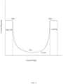
- Figure 3 is a diagram illustrating an embodiment of aircraft current requirements during flight.
- the diagram shown graphs current required by the aircraft against time of flight. During period 300, take-off, the current required is at a peak level. The current required dips and is low during cruise until peaking again during landing period 304. As shown, the aircraft is in cruise for the majority of flight.
- FIG. 4 is a flow diagram illustrating an embodiment of a hybrid battery process.
- it is determined whether high power levels are required.
- the power dense battery takes the majority of the load.
- the power dense battery supplies a higher current than the energy dense battery does to a shared bus.
- the power dense batteries may be capable of putting out high currents without sustaining damage, unlike energy dense batteries.
- the energy dense battery takes the majority of the load. Using an energy dense battery in the event high power levels are not required may be efficient or cost-effective.
- flight is complete e.g. whether the aircraft has landed. In the event flight is not complete, subsequent iterations of the process are repeated.
- the main load is shifted between the two types of batteries using various methods.
- the shifting of the load between the types of batteries may be achieved by utilizing or manipulating electrical switches, battery cell geometry, battery cell quantities, battery positioning in the system, or battery cell chemistry.
- the power dense battery takes the majority of the load only in the event that high power levels are required and the energy dense battery is unable to supply the required power.
- the power dense battery and energy dense battery share the load during take-off, when high power levels are required and both types of batteries are fully charged. As the batteries are drained and reach a lower percentage of charge later in flight, such as during landing, the energy dense battery may experience a voltage drop under high loads, causing the power dense battery to take the majority of the load when high power levels are required.
- FIG. 5 is a diagram illustrating an embodiment of a hybrid battery system with switches.
- Energy dense battery 500, power dense battery 502, and motor 504 are in parallel.
- multiple power dense batteries and multiple motors are in parallel with an energy dense battery.
- Energy dense battery 500 and power dense battery 502 may sit at the same voltage in steady state because they are in parallel.
- the batteries may supply current relative to their impedances.
- Motor 504 or any appropriate load is powered by the supplied current.
- the batteries are wired to a shared bus, wherein the motor and any additional motors or actuators draw current from the shared bus.
- throttling a motor up causes it to draw current from all batteries whereas throttling it down causes its respective outboard battery to put some current on the bus.
- each battery has a switch. The energy dense battery and power dense battery may be switched into or out of the circuit depending on which is needed or desired to be used.
- Figure 6 is a flow diagram illustrating an embodiment of a process to switch batteries in a hybrid battery system.
- the energy dense battery is switched out and the power dense battery switched in during take-off and landing while the energy dense battery is switched in and the power dense battery switched out during steady-state flight (e.g. cruise). Switching may be done to ensure the power dense battery powers the aircraft during take-off and landing and the energy dense battery powers the aircraft during steady state flight.
- fewer switches are performed and the two types of batteries are simultaneously online during specific periods of flight. In some embodiments, switching is not required to shift the load between the two batteries due to the energy dense battery's voltage drop under high load. Switching may be performed as a safeguard to protect a battery from damage.
- the energy dense battery and the power dense battery are charged.
- the aircraft at this point in the process is grounded and may be attached to an external power source.
- the power dense battery may have a lower energy density than the energy dense battery, causing the power dense battery to become fully charged in a shorter time.
- the power dense battery may be removed to prevent it from being overcharged, which can cause damage.
- the process returns to 602.
- the energy dense battery and the power dense battery are put online. In this example, both batteries are used simultaneously.
- the majority of the load may be taken by the energy dense battery.
- the aircraft may enter a cruise state. During cruise, the energy dense battery may take the majority of the load.
- the energy dense battery may take the majority of the load while it is at a highly charged state (e.g. 100 to 50 percent charged).
- the energy dense battery may be taken offline to prevent it from being damaged and ensure that the load is taken by the power dense battery. In the event that the energy dense battery is at a low charged state and high power is required (as is expected during landing of a VTOL aircraft), the energy dense battery may fail to provide the required power, requiring the presence of a power dense battery.
- switching is not required because the load is passively shifted between the two types of batteries due to their characteristics.
- An energy dense battery may experience a larger voltage drop than a power dense battery under a high load, causing the power dense battery to take on the majority of the load.
- FIG. 7A is a diagram illustrating an embodiment of a cylindrical battery.
- a cylindrical battery may be used in a hybrid battery system as an energy dense battery or central battery.
- a common example of a cylindrical battery is an 18650 cell.
- Cylindrical batteries have extremely high energy content. However, it is difficult to achieve a high discharge rate or high power level with a cylindrical battery. Cylindrical batteries tend to cheap to manufacture and acquire.
- FIG. 7B is a diagram illustrating an embodiment of a cylindrical battery in unrolled form.
- battery 704 comprises a layer of cathode and a layer of anode with an electrolyte in between. Current transfers through tab 702.
- FIG. 7C is a diagram illustrating an embodiment of a pouch battery.
- a pouch battery may be used in a hybrid battery system as a power dense battery.
- Pouch battery 710 as shown is a relatively flat shape.
- a pouch battery have a high discharge rate but is less efficient at storing energy as compared to a cylindrical battery. The majority of flight may be powered using a cheap, easily replaceable 18650 battery while pouch cells provide needed punches of power.
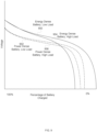
- Figure 8 is a diagram illustrating an embodiment of cylindrical (energy dense) battery and pouch (power dense) battery voltage curves.
- the graph displays voltage against battery percentage of the two batteries.
- the voltage refers to the voltage of the shared bus and of the batteries, wherein the batteries are in parallel.
- the voltage curves of the batteries differ due to the different geometries of the batteries.
- the voltage curves shown may exemplify battery performance in the event that only one battery is present (e.g. curve 800 shows how an energy dense battery would perform alone).
- a cylindrical battery and a pouch battery may have similar voltage curves or the same voltage curve at a high charge percentage and under low load (e.g. supplying 1 Amp).
- a high load e.g. supplying 10 Amps
- the voltage of the energy dense battery droops far more than the voltage of the power dense battery. Due to the voltage drop of the energy dense battery, the power dense battery may take more of the load or supply a higher current than the energy dense battery under a high load.
- voltage curve 800 is the voltage curve of an energy dense battery under a low load.
- Voltage curve 806 shows an energy dense battery under a high load. Under a high load, the voltage droops considerably.
- FIG. 9 is a diagram illustrating an embodiment of cylindrical (energy dense) battery and pouch (power dense) battery voltage curves with varying cell counts.
- An energy dense battery used in a hybrid battery system may have a higher battery cell count than a power dense battery used in the system in order to prevent the power dense battery from being used up before landing.
- the voltage curve of an energy dense battery under a low load (curve 900) is situated above the voltage curve of a power dense battery under a low load (curve 902).
- the energy dense battery pack may comprise more battery cells than the power dense battery pack, causing the energy dense battery voltage curve to be at a higher voltage when both battery packs are 100% charged. In steady state, the voltages of the energy dense battery pack and the power dense battery pack are equal.
- the energy dense battery may provide more power (e.g. supply a higher current) than the power dense battery due to the offset between the voltage curves (e.g. 900 and 902).
- the energy dense battery will discharge faster and supply more current than the power dense battery pack.
- the power dense battery pack is at a lower stage of discharge as compared to the energy dense battery pack when the voltages of the packs are equal, due to the uneven number of cells.
- a high discharge rate is applied to the battery packs (e.g. a high load)
- both voltage curves droop as shown with curves 904 (energy dense battery under a high load) and 906 (power dense battery under a high load).
- the pouch battery is at a lower state of discharge and it droops less. Curves 904 and 906 cross as shown, with the power dense battery curve above the energy dense battery curve.
- the power dense battery will provide the majority of the power under a high load when the energy dense battery is reaching a low charged percentage.
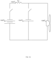
- FIG 10 is a diagram illustrating an embodiment of hybrid battery system with wire resistance.
- the two types of batteries may be located on the aircraft in positions that take advantage of wire resistance.
- energy dense battery 1000, power dense battery 1004, and motor 1006 are in parallel.
- Wire resistance 1002 is represented as Rw.
- Energy dense battery 1000 may be positioned far from power dense battery 1004, with many lengths of wire between.
- the wire or wire harness may cause a voltage drop (e.g. up to 2%) under high loads when current is drawn from the energy dense battery. Due to the voltage drop, more power may be naturally drawn from an outboard/power dense battery when high power is needed. Under low loads, the voltage drop may be negligible, allowing the energy dense battery to take on a disproportionate amount of load.
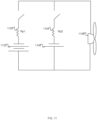
- FIG 11 is a diagram illustrating an embodiment of hybrid battery system with battery pack resistance.
- the energy dense battery may be designed to have more resistance in the pack as compared to the power dense battery to cause the energy dense battery to supply less power than the power dense battery under high loads.
- energy dense battery 1102, power dense battery 1106, and motor 1108 are in parallel.
- Battery pack resistance is represented as Rpl for the energy dense battery and Rp2 for the power dense battery. Rpl may be greater than Rp2.
- the two types of batteries comprise different cell chemistries. Electrolyte type, anode type, cathode type, electrolyte thickness, or component concentrations may be changed in order to produce desired battery packs. Cell chemistries may be adjusted to cause the voltage curves of battery packs to appear as in Figure 11 .
- Figure 12 is a flow diagram illustrating an embodiment of a process to shift load between batteries in a hybrid battery system.
- the load may be shifted due to the characteristics of the two types of battery packs under a high discharge rate.
- the characteristics of the two types of batteries may be carefully chosen or designed based on cell geometry, cell chemistry, cell counts, positioning, designed resistance, or any other appropriate factor.
- the energy dense battery's voltage droops and the power dense battery powers the aircraft.
- the determination at 1204 is whether the aircraft is in a high power stage of flight and the energy dense battery is at a low charge percentage.
Landscapes
- Engineering & Computer Science (AREA)
- Power Engineering (AREA)
- General Chemical & Material Sciences (AREA)
- Electrochemistry (AREA)
- Chemical Kinetics & Catalysis (AREA)
- Chemical & Material Sciences (AREA)
- Aviation & Aerospace Engineering (AREA)
- Manufacturing & Machinery (AREA)
- Mechanical Engineering (AREA)
- Transportation (AREA)
- Sustainable Energy (AREA)
- Sustainable Development (AREA)
- Life Sciences & Earth Sciences (AREA)
- Charge And Discharge Circuits For Batteries Or The Like (AREA)
- Battery Mounting, Suspending (AREA)
- Secondary Cells (AREA)
Description
- In vertical take-off and landing (VTOL) aircraft, large amounts of power are applied at the start and end of flight to enable the aircraft to take off and land in a short distance. In an electric VTOL aircraft, a battery or battery system must sustain the aircraft for the entirety of flight as well as supply surges of power during take-off and landing. A high energy density battery may be used to provide a cost-effective and weight-effective solution to powering an aircraft. A high energy density battery may not be capable of supplying the power needed for vertical take-off or landing without sustaining damage to the battery. Towards the end of flight, a typical high energy density battery may output too low of a voltage for a vertical landing.
-
US 2014/111121 describes a power delivery system for an electric vehicle, which provides power management for either continuous or intermittent high-performance operation, using a boost stage and an on-board charging circuit. A main battery, configured as a high-capacity power source, supplies power to the electric motor under normal load conditions. An auxiliary boost battery assists the main battery in supplying a high-level current at a higher discharge rate thereby causing the motor to operate in a high-performance drive mode. A charging circuit recharges the boost battery from the main battery during operation of the motor. The charging circuit also maintains a charge balance between the boost battery and the main battery when the two batteries have different chemistries. -
US 2015/202984 describes a 12 volt automotive battery system, which includes a first battery coupled to an electrical system, in which the first battery include a first battery chemistry, and a second battery coupled in parallel with the first battery and selectively coupled to the electrical system via a first switch, in which the second battery includes a second battery chemistry that has a higher coulombic efficiency than the first battery chemistry. The first switch couples the second battery to the electrical system during regenerative braking to enable the second battery to capture a majority of the power generated during regenerative braking. The 12 volt automotive battery system further includes a variable voltage alternator that outputs a first voltage during regenerative braking to charge the second battery and a second voltage otherwise, in which the first voltage is higher than the second voltage. -
US 4,025,860 describes an electric auto power supply, which has an energy battery which is capable of discharging a current for a comparatively long period of time and high in energy density, and a power battery which is capable of discharging a current of a comparatively high amperage and high in power density. The energy battery and the power battery are connected respectively by way of switching means in parallel relation to each other, so as to be used as a power source of an electromobile. The current discharged from these batteries is controlled, such that a current required for the travelling of the electromobile, which is dependent upon the travelling conditions thereof, is supplied simultaneously from both batteries, or separately from individual batteries, or otherwise only from one battery, while a current is being charged to the other battery, thus extending the possible mileage range of the electromobile. -
US 2016/221683 describes methods and systems for supplying auxiliary power to an unmanned aerial vehicle (UAV) with different flight modes. The system may determine that a UAV is operating in a first flight mode. Responsively, the system may cause the UAV to draw power from a first power source at a first power level while operating in the first flight mode. Subsequently, the system may determine that the UAV switched from operating in the first flight mode to operating in a second flight mode. Responsively, the system may cause the UAV, while operating in the second flight mode, to continue drawing power from the first power source at the first power level and draw power from a second power source at a second power level, where the UAV consumes power at a higher rate during the second flight mode than during the first flight mode. - Various embodiments of the invention are disclosed in the following detailed description and the accompanying drawings.
-
Figure 1 is a diagram illustrating an embodiment of a hybrid battery system. -
Figure 2 is a diagram illustrating an embodiment of an aircraft that utilizes a hybrid battery system. -
Figure 3 is a diagram illustrating an embodiment of aircraft current requirements during flight. -
Figure 4 is a flow diagram illustrating an embodiment of a hybrid battery process. -
Figure 5 is a diagram illustrating an embodiment of a hybrid battery system with switches. -
Figure 6 is a flow diagram illustrating an embodiment of a process to switch batteries in a hybrid battery system. -
Figure 7A is a diagram illustrating an embodiment of a cylindrical battery. -
Figure 7B is a diagram illustrating an embodiment of a cylindrical battery in unrolled form. -
Figure 7C is a diagram illustrating an embodiment of a pouch battery. -
Figure 8 is a diagram illustrating an embodiment of cylindrical battery and pouch battery voltage curves. -
Figure 9 is a diagram illustrating an embodiment of cylindrical battery and pouch battery voltage curves under varying cell counts. -
Figure 10 is a diagram illustrating an embodiment of hybrid battery system with wire resistance. -
Figure 11 is a diagram illustrating an embodiment of hybrid battery system with battery pack resistance. -
Figure 12 is a flow diagram illustrating an embodiment of a process to shift load between batteries in a hybrid battery system. - The invention can be implemented in numerous ways, including as a process; an apparatus; a system; a composition of matter; a computer program product embodied on a computer readable storage medium; and/or a processor, such as a processor configured to execute instructions stored on and/or provided by a memory coupled to the processor. In this specification, these implementations, or any other form that the invention may take, may be referred to as techniques. In general, the order of the steps of disclosed processes may be altered within the scope of the invention. Unless stated otherwise, a component such as a processor or a memory described as being configured to perform a task may be implemented as a general component that is temporarily configured to perform the task at a given time or a specific component that is manufactured to perform the task. As used herein, the term 'processor' refers to one or more devices, circuits, and/or processing cores configured to process data, such as computer program instructions.
- A detailed description of one or more embodiments of the invention is provided below along with accompanying figures that illustrate the principles of the invention. The invention is described in connection with such embodiments, but the invention is not limited to any embodiment. The scope of the invention is limited only by the claims and the invention encompasses numerous alternatives, modifications and equivalents. Numerous specific details are set forth in the following description in order to provide a thorough understanding of the invention. These details are provided for the purpose of example and the invention may be practiced according to the claims without some or all of these specific details. For the purpose of clarity, technical material that is known in the technical fields related to the invention has not been described in detail so that the invention is not unnecessarily obscured.
- An electrically-powered vehicle comprising a hybrid battery system is disclosed. The vehicle comprises a motor and a hybrid battery system coupled to the motor. The hybrid battery system comprises a first battery of a first energy density and a first power density and a second battery in parallel with the first battery. The second battery has a second energy density lower than the first energy density and a second power density greater than the first power density. The vehicle is configured to draw power disproportionally from the first battery in a first mode and is configured to draw power disproportionally from the second battery in a second mode.
- In a hybrid battery system, two different types of batteries are used to power an electric aircraft in combination or separately. During steady state flight, a high energy density battery may be used. A high energy density battery may efficiently provide the low amounts of power needed to sustain cruise in the aircraft. Towards the end of flight, the high energy density battery may be drained and output a voltage too low to sustain a vertical or power-intensive landing. At or close to landing, the aircraft's main source of power changes to a second type of battery. The second type of battery may comprise a power dense battery with a high discharge rate, wherein the battery is capable of sustaining a large current.
- Common cost-effective high energy density batteries may have low discharge rates. They are able to sustain low currents for long periods of time but cannot sustain high currents without incurring damage. For the purposes of the application, energy dense battery, high energy density battery and low discharge rate battery are used interchangeably to refer to a high energy density, low power density battery. Common cost-effective power dense batteries may have low energy densities. Power dense battery and high discharge rate battery refer to a low energy density, high power density battery (e.g. relative to an energy dense battery). In some embodiments, an energy dense battery or a power dense battery used in a hybrid battery system is rechargeable.
-
Figure 1 is a diagram illustrating an embodiment of a hybrid battery system. The hybrid battery system comprises an energy dense battery that is placed centrally in an aircraft and one or more power dense batteries that are placed near motors of the aircraft. In the example shown,central battery 116,outboard battery 104, andoutboard battery 112 are wired together. The batteries may powermotors propellers Outboard battery 104 is positioned along withmotor 102 withinpod 106, on whichpropeller 100 is installed.Outboard battery 112 is positioned along withmotor 110 withinpod 114, on whichpropeller 108 is installed.Central battery 116 as shown is positioned outside of the pods and away from the motors. -
Figure 2 is a diagram illustrating an embodiment of an aircraft that utilizes a hybrid battery system. As shown,central battery 217 is positioned in the fuselage of aircraft 216.Front wing 208 comprises propellers extending frompods Outboard batteries pods pods batteries -
Central battery 217 may comprise an energy dense battery whereas the outboard batteries comprise power dense batteries. The outboard batteries may be capable of providing enough power to land the aircraft in the absence of the central battery. Each individual outboard battery may be capable of supplying enough power to sustain its corresponding motor through a landing, allowing each pod to operate independently. The distributed positioning of the outboard batteries may decrease chances of a single trauma affecting the aircraft's ability to land. In some embodiments, the aircraft is over-actuated (e.g. the aircraft is able to maintain controlled flight with fewer rotors than it possesses) and distributing the batteries takes advantage of the over-actuated design. - Retaining a central battery may enable the hybrid battery system to stay within weight constraints as opposed to distributing all batteries. The outboard batteries may provide a form of redundancy by providing boosts of power during launch and landing, when the central battery may need to be supplemented.
- In some embodiments, the hybrid battery system is used to power the flight control assets of the aircraft, which may include one or more of control surfaces, such as rudders, ailerons, elevators, etc.; sources of forward thrust, such as propellers or jet engines; powered sources of lift such as rotors or lift fans; and forces capable of being directed or otherwise controlled or concentrated through use of nozzles, diverters, physical structures onto which engine or fan thrust may be directed, such as vanes, etc. and/or rotation of thrust generating devices.
-
Figure 3 is a diagram illustrating an embodiment of aircraft current requirements during flight. The diagram shown graphs current required by the aircraft against time of flight. Duringperiod 300, take-off, the current required is at a peak level. The current required dips and is low during cruise until peaking again duringlanding period 304. As shown, the aircraft is in cruise for the majority of flight. -
Figure 4 is a flow diagram illustrating an embodiment of a hybrid battery process. At 400, it is determined whether high power levels are required. In the event high power levels are required, at 402 the power dense battery takes the majority of the load. For example, the power dense battery supplies a higher current than the energy dense battery does to a shared bus. The power dense batteries may be capable of putting out high currents without sustaining damage, unlike energy dense batteries. In the event high power levels are not required, at 404 the energy dense battery takes the majority of the load. Using an energy dense battery in the event high power levels are not required may be efficient or cost-effective. Following 402 or 404, it is determined at 406 whether flight is complete (e.g. whether the aircraft has landed). In the event flight is not complete, subsequent iterations of the process are repeated. - In various embodiments, the main load is shifted between the two types of batteries using various methods. The shifting of the load between the types of batteries may be achieved by utilizing or manipulating electrical switches, battery cell geometry, battery cell quantities, battery positioning in the system, or battery cell chemistry.
- In some embodiments, the power dense battery takes the majority of the load only in the event that high power levels are required and the energy dense battery is unable to supply the required power. In some embodiments, the power dense battery and energy dense battery share the load during take-off, when high power levels are required and both types of batteries are fully charged. As the batteries are drained and reach a lower percentage of charge later in flight, such as during landing, the energy dense battery may experience a voltage drop under high loads, causing the power dense battery to take the majority of the load when high power levels are required.
-
Figure 5 is a diagram illustrating an embodiment of a hybrid battery system with switches. Energydense battery 500, power dense battery 502, andmotor 504 are in parallel. In some embodiments, multiple power dense batteries and multiple motors are in parallel with an energy dense battery. Energydense battery 500 and power dense battery 502 may sit at the same voltage in steady state because they are in parallel. The batteries may supply current relative to their impedances.Motor 504 or any appropriate load is powered by the supplied current. The batteries are wired to a shared bus, wherein the motor and any additional motors or actuators draw current from the shared bus. - Current may tend to flow from local outboard batteries to their respective local motors due to wire resistance. In some embodiments, throttling a motor up causes it to draw current from all batteries whereas throttling it down causes its respective outboard battery to put some current on the bus. As shown, each battery has a switch. The energy dense battery and power dense battery may be switched into or out of the circuit depending on which is needed or desired to be used.
-
Figure 6 is a flow diagram illustrating an embodiment of a process to switch batteries in a hybrid battery system. In some embodiments, the energy dense battery is switched out and the power dense battery switched in during take-off and landing while the energy dense battery is switched in and the power dense battery switched out during steady-state flight (e.g. cruise). Switching may be done to ensure the power dense battery powers the aircraft during take-off and landing and the energy dense battery powers the aircraft during steady state flight. - In some embodiments, fewer switches are performed and the two types of batteries are simultaneously online during specific periods of flight. In some embodiments, switching is not required to shift the load between the two batteries due to the energy dense battery's voltage drop under high load. Switching may be performed as a safeguard to protect a battery from damage.
- At 600, the energy dense battery and the power dense battery are charged. The aircraft at this point in the process is grounded and may be attached to an external power source. At 602, it is determined whether the power dense battery is fully charged. In the event the power dense battery is fully charged, at 604 the power dense battery is taken offline. The power dense battery may have a lower energy density than the energy dense battery, causing the power dense battery to become fully charged in a shorter time. The power dense battery may be removed to prevent it from being overcharged, which can cause damage.
- In the event the power dense battery is taken offline or is not fully charged, at 606 it is determined whether the aircraft is taking off. In the event the aircraft is not taking off, the process returns to 602. In the event the aircraft is taking off, at 608 the energy dense battery and the power dense battery are put online. In this example, both batteries are used simultaneously. The majority of the load may be taken by the energy dense battery. Following take-off, the aircraft may enter a cruise state. During cruise, the energy dense battery may take the majority of the load. The energy dense battery may take the majority of the load while it is at a highly charged state (e.g. 100 to 50 percent charged). At 610, it is determined whether the aircraft is landing. When it is determined that the aircraft is landing, at 612 the energy dense battery is taken offline. The energy dense battery may be taken offline to prevent it from being damaged and ensure that the load is taken by the power dense battery. In the event that the energy dense battery is at a low charged state and high power is required (as is expected during landing of a VTOL aircraft), the energy dense battery may fail to provide the required power, requiring the presence of a power dense battery.
- In some embodiments, switching is not required because the load is passively shifted between the two types of batteries due to their characteristics. An energy dense battery may experience a larger voltage drop than a power dense battery under a high load, causing the power dense battery to take on the majority of the load.
-
Figure 7A is a diagram illustrating an embodiment of a cylindrical battery. A cylindrical battery may be used in a hybrid battery system as an energy dense battery or central battery. A common example of a cylindrical battery is an 18650 cell. Cylindrical batteries have extremely high energy content. However, it is difficult to achieve a high discharge rate or high power level with a cylindrical battery. Cylindrical batteries tend to cheap to manufacture and acquire. -
Figure 7B is a diagram illustrating an embodiment of a cylindrical battery in unrolled form. In the example shown,battery 704 comprises a layer of cathode and a layer of anode with an electrolyte in between. Current transfers throughtab 702. -
Figure 7C is a diagram illustrating an embodiment of a pouch battery. A pouch battery may be used in a hybrid battery system as a power dense battery.Pouch battery 710 as shown is a relatively flat shape. A pouch battery have a high discharge rate but is less efficient at storing energy as compared to a cylindrical battery. The majority of flight may be powered using a cheap, easily replaceable 18650 battery while pouch cells provide needed punches of power. -
Figure 8 is a diagram illustrating an embodiment of cylindrical (energy dense) battery and pouch (power dense) battery voltage curves. The graph displays voltage against battery percentage of the two batteries. The voltage refers to the voltage of the shared bus and of the batteries, wherein the batteries are in parallel. The voltage curves of the batteries differ due to the different geometries of the batteries. The voltage curves shown may exemplify battery performance in the event that only one battery is present (e.g. curve 800 shows how an energy dense battery would perform alone). - Assuming similar chemistry, a cylindrical battery and a pouch battery may have similar voltage curves or the same voltage curve at a high charge percentage and under low load (e.g. supplying 1 Amp). However, under a high load (e.g. supplying 10 Amps), the voltage of the energy dense battery droops far more than the voltage of the power dense battery. Due to the voltage drop of the energy dense battery, the power dense battery may take more of the load or supply a higher current than the energy dense battery under a high load.
- As shown,
voltage curve 800 is the voltage curve of an energy dense battery under a low load.Voltage curve 806 shows an energy dense battery under a high load. Under a high load, the voltage droops considerably.Voltage curve 802, which shows a power dense battery under a low load, also droops under a high load as shown by voltage curve 804 (power dense battery under a high load). However, it does not droop as much due to the geometry of the battery. -
Figure 9 is a diagram illustrating an embodiment of cylindrical (energy dense) battery and pouch (power dense) battery voltage curves with varying cell counts. An energy dense battery used in a hybrid battery system may have a higher battery cell count than a power dense battery used in the system in order to prevent the power dense battery from being used up before landing. In the example shown, the voltage curve of an energy dense battery under a low load (curve 900) is situated above the voltage curve of a power dense battery under a low load (curve 902). The energy dense battery pack may comprise more battery cells than the power dense battery pack, causing the energy dense battery voltage curve to be at a higher voltage when both battery packs are 100% charged. In steady state, the voltages of the energy dense battery pack and the power dense battery pack are equal. Under steady state (e.g. low load), the energy dense battery may provide more power (e.g. supply a higher current) than the power dense battery due to the offset between the voltage curves (e.g. 900 and 902). The energy dense battery will discharge faster and supply more current than the power dense battery pack. - The power dense battery pack is at a lower stage of discharge as compared to the energy dense battery pack when the voltages of the packs are equal, due to the uneven number of cells. When a high discharge rate is applied to the battery packs (e.g. a high load), both voltage curves droop as shown with curves 904 (energy dense battery under a high load) and 906 (power dense battery under a high load). The pouch battery is at a lower state of discharge and it droops less.
Curves -
Figure 10 is a diagram illustrating an embodiment of hybrid battery system with wire resistance. The two types of batteries may be located on the aircraft in positions that take advantage of wire resistance. In the example shown, energydense battery 1000, power dense battery 1004, andmotor 1006 are in parallel.Wire resistance 1002 is represented as Rw. Energydense battery 1000 may be positioned far from power dense battery 1004, with many lengths of wire between. The wire or wire harness may cause a voltage drop (e.g. up to 2%) under high loads when current is drawn from the energy dense battery. Due to the voltage drop, more power may be naturally drawn from an outboard/power dense battery when high power is needed. Under low loads, the voltage drop may be negligible, allowing the energy dense battery to take on a disproportionate amount of load. -
Figure 11 is a diagram illustrating an embodiment of hybrid battery system with battery pack resistance. The energy dense battery may be designed to have more resistance in the pack as compared to the power dense battery to cause the energy dense battery to supply less power than the power dense battery under high loads. In the example shown, energydense battery 1102, power dense battery 1106, andmotor 1108 are in parallel. Battery pack resistance is represented as Rpl for the energy dense battery and Rp2 for the power dense battery. Rpl may be greater than Rp2. - In some embodiments, the two types of batteries comprise different cell chemistries. Electrolyte type, anode type, cathode type, electrolyte thickness, or component concentrations may be changed in order to produce desired battery packs. Cell chemistries may be adjusted to cause the voltage curves of battery packs to appear as in
Figure 11 . -
Figure 12 is a flow diagram illustrating an embodiment of a process to shift load between batteries in a hybrid battery system. The load may be shifted due to the characteristics of the two types of battery packs under a high discharge rate. The characteristics of the two types of batteries may be carefully chosen or designed based on cell geometry, cell chemistry, cell counts, positioning, designed resistance, or any other appropriate factor. At 1200, it is determined whether the aircraft is in steady state. In the event the aircraft is in steady state, at 1202 the energy dense battery powers the aircraft. Following 1202 or in the event the aircraft is not in steady state, at 1204 it is determined whether the aircraft is in a high power stage of flight. In the event the aircraft is in a high power stage of flight, at 1206 the energy dense battery's voltage droops and the power dense battery powers the aircraft. In some embodiments, the determination at 1204 is whether the aircraft is in a high power stage of flight and the energy dense battery is at a low charge percentage. At 1208, it is determined whether flight is complete. In the event flight is not complete, the process repeats. - Although the foregoing embodiments have been described in some detail for purposes of clarity of understanding, the invention is not limited to the details provided. There are many alternative ways of implementing the invention. The disclosed embodiments are illustrative and not restrictive.
Claims (14)
- An electrically-powered vehicle (216), comprising:a motor; anda hybrid battery system coupled to the motor (102, 110) of an electrically powered vehicle (216), comprising:a first battery (116; 217) of a first energy density and a first power density; anda second battery (104, 112; 208, 210, 212, 214, 226, 228, 230, 232) in parallel with the first battery, wherein the second battery has a second energy density lower than the first energy density and a second power density greater than the first power density,wherein the first battery is operative to supply a higher current to a shared bus than the second battery in a first mode and the second battery is operative to supply a higher current to the shared bus than the first battery in a second mode, characterized in that the secondary battery is stored outboard in the vehicle.
- The electrically-powered vehicle (216) of claim 1, wherein the first battery (116; 217) and the second battery (104, 112; 208, 210, 212, 214, 226, 228, 230, 232) are in parallel with a component of the vehicle (216) to which the batteries provide power.
- The electrically-powered vehicle (216) of claim 1, wherein the first battery (116; 217) is stored centrally in the vehicle (216).
- The electrically-powered vehicle (216) of claim 1, wherein the second battery (104, 112; 208, 210, 212, 214, 226, 228, 230, 232) is stored adjacent to a component of the vehicle (216) to which it provides power.
- The electrically-powered vehicle (216) of claim 1, wherein the first mode comprises a low power mode in which a low discharge rate is applied to the first and second batteries.
- The electrically-powered vehicle (216) of claim 1, wherein the second mode comprises a high power mode in which a high discharge rate is applied to the first and second batteries.
- The electrically-powered vehicle (216) of claim 1, wherein the first battery (116; 217) and the second battery (104, 112; 208, 210, 212, 214, 226, 228, 230, 232) are switched in to or out of a shared bus.
- The electrically-powered vehicle (216) of claim 1, wherein the first battery (116; 217) drops in voltage more significantly under load than the second battery (104, 112; 208, 210, 212, 214, 226, 228, 230, 232) such that greater current is drawn from the second battery under high load.
- The electrically-powered vehicle (216) of claim 1, wherein the first battery (116; 217) has a larger battery cell count than the second battery (104, 112; 208, 210, 212, 214, 226, 228, 230, 232).
- The electrically-powered vehicle (216) of claim 1, wherein:(i) the first battery (116; 217) comprises a cylindrical battery; or(ii) the second battery (104, 112; 208, 210, 212, 214, 226, 228, 230, 232) comprises a pouch battery.
- The electrically-powered vehicle (216) of claim 1, wherein the vehicle comprises an aircraft (216).
- The electrically-powered vehicle (216) of claim 1, wherein the vehicle comprises a vertical take-off and landing aircraft; optionally,wherein the second battery (208, 210, 212, 214, 226, 228, 230, 232) and one or more additional batteries of high power densities that are in parallel with the second battery provide enough power to vertically land the aircraft in the absence of the first battery (217);
further optionally,wherein the second battery and one or more additional batteries of high power densities are each individually capable of powering a single motor that is located near each battery, respectively. - The electrically-powered vehicle (216) of claim 1, wherein the first mode comprises a cruise or steady-state flight mode and the second mode comprises take-off or landing.
- A method of powering a vehicle (216), comprising:drawing a higher current from a first battery (116; 217) than a second battery (104, 112; 208, 210, 212, 214, 226, 228, 230, 232) in a first mode, wherein the second battery is connected in parallel with the first battery via a shared bus; anddrawing a higher current from the second battery than the first battery in a second mode,wherein the first battery is of a first energy density and a first power density and the second battery is of a second energy density lower than the first energy density and a second power density greater than the first power density, characterised in that the second battery is stored outboard in the vehicle.
Applications Claiming Priority (2)
| Application Number | Priority Date | Filing Date | Title |
|---|---|---|---|
| US15/607,250 US10153636B1 (en) | 2017-05-26 | 2017-05-26 | Electric vehicle hybrid battery system |
| PCT/US2017/034950 WO2018217218A1 (en) | 2017-05-26 | 2017-05-30 | Electric vehicle hybrid battery system |
Publications (3)
| Publication Number | Publication Date |
|---|---|
| EP3631887A1 EP3631887A1 (en) | 2020-04-08 |
| EP3631887A4 EP3631887A4 (en) | 2021-03-03 |
| EP3631887B1 true EP3631887B1 (en) | 2024-09-04 |
Family
ID=64395779
Family Applications (1)
| Application Number | Title | Priority Date | Filing Date |
|---|---|---|---|
| EP17910620.8A Active EP3631887B1 (en) | 2017-05-26 | 2017-05-30 | Electric vehicle hybrid battery system |
Country Status (6)
| Country | Link |
|---|---|
| US (1) | US10153636B1 (en) |
| EP (1) | EP3631887B1 (en) |
| JP (1) | JP7084676B2 (en) |
| CN (1) | CN110678393B (en) |
| AU (1) | AU2017415649B2 (en) |
| WO (1) | WO2018217218A1 (en) |
Families Citing this family (35)
| Publication number | Priority date | Publication date | Assignee | Title |
|---|---|---|---|---|
| WO2019241581A1 (en) * | 2018-06-16 | 2019-12-19 | Marinus Bernard Bosma | Electrically-powered aircraft with pod-mounted batteries |
| DE102018116167B4 (en) * | 2018-07-04 | 2024-03-21 | Dr. Ing. H.C. F. Porsche Aktiengesellschaft | aircraft |
| DE102018116148A1 (en) * | 2018-07-04 | 2020-01-09 | Dr. Ing. H.C. F. Porsche Aktiengesellschaft | aircraft |
| WO2020180368A2 (en) | 2019-03-01 | 2020-09-10 | United Technologies Advanced Projects, Inc. | Aircraft having hybrid-electric propulsion system with electric storage located in fuselage |
| EP3798130B1 (en) | 2019-09-30 | 2023-03-01 | Hamilton Sundstrand Corporation | Systems and methods for battery ventilation |
| CN114375276B (en) * | 2019-10-09 | 2024-12-24 | 小鹰公司 | Short take-off and landing vehicle with forward-swept wings |
| CN114867658B (en) * | 2019-12-25 | 2025-06-10 | 松下知识产权经营株式会社 | Flying body |
| CN113594637A (en) | 2020-04-30 | 2021-11-02 | 宁德时代新能源科技股份有限公司 | Battery module, device, battery pack, and method and apparatus for manufacturing battery module |
| EP4020691B1 (en) * | 2020-07-29 | 2023-10-18 | Contemporary Amperex Technology Co., Limited | Battery module, battery pack, apparatus, and method and device for manufacturing battery module |
| US11495982B2 (en) * | 2020-08-31 | 2022-11-08 | The Boeing Company | System and method for allocating propulsion load power drawn from high-energy and high-power batteries |
| KR102773790B1 (en) | 2020-09-30 | 2025-02-27 | 컨템포러리 엠퍼렉스 테크놀로지 (홍콩) 리미티드 | Battery, device, battery manufacturing method and battery manufacturing device |
| JP7674361B2 (en) | 2020-09-30 | 2025-05-09 | 香港時代新能源科技有限公司 | Battery, device, battery manufacturing method and manufacturing device |
| JP7569481B2 (en) | 2020-09-30 | 2024-10-18 | 香港時代新能源科技有限公司 | Battery, device, battery manufacturing method and manufacturing device |
| CN115699406B (en) | 2020-11-17 | 2024-10-01 | 宁德时代新能源科技股份有限公司 | Battery, device using battery, method for preparing battery, and preparation equipment |
| CN114982011B (en) | 2020-12-24 | 2024-04-05 | 宁德时代新能源科技股份有限公司 | Battery module, manufacturing method and equipment thereof, battery pack and electricity utilization device |
| US11772805B2 (en) | 2021-02-11 | 2023-10-03 | Textron Innovations Inc. | Configurable electrical architectures for eVTOL aircraft |
| GB2605357B (en) | 2021-02-24 | 2024-05-01 | Mclaren Automotive Ltd | Battery system |
| JP2022137750A (en) * | 2021-03-09 | 2022-09-22 | 本田技研工業株式会社 | Aircraft propulsion system and method of manufacturing aircraft |
| DE102021110774A1 (en) | 2021-04-27 | 2022-10-27 | Rolls-Royce Deutschland Ltd & Co Kg | Electric propulsion system |
| US11447035B1 (en) * | 2021-05-04 | 2022-09-20 | Textron Innovations Inc. | Battery system optimization for eVTOL aircraft |
| US12489132B2 (en) * | 2021-05-09 | 2025-12-02 | Textron Innovations Inc. | Lightweight fuel cell stack end plate |
| US11999509B2 (en) | 2021-05-17 | 2024-06-04 | Pratt & Whitney Canada Corp. | Hybrid-electric and all-electric aircraft power systems |
| US11594779B2 (en) | 2021-06-16 | 2023-02-28 | Beta Air, Llc | Battery pack for electric vertical take-off and landing aircraft |
| WO2023004774A1 (en) | 2021-07-30 | 2023-02-02 | 宁德时代新能源科技股份有限公司 | Battery group, battery pack and electric apparatus |
| JP2023025980A (en) * | 2021-08-11 | 2023-02-24 | Ysec株式会社 | battery charging system |
| CN115891684B (en) * | 2021-09-30 | 2025-03-21 | 比亚迪股份有限公司 | Battery pack and automobile |
| US11993368B2 (en) * | 2022-04-29 | 2024-05-28 | Beta Air, Llc | Hybrid electric vertical takeoff and landing aircraft |
| US11655024B1 (en) | 2022-05-25 | 2023-05-23 | Kitty Hawk Corporation | Battery systems with power optimized energy source and energy storage optimized source |
| US11848458B1 (en) * | 2022-10-19 | 2023-12-19 | Cuberg, Inc. | Battery module configured for use in an electric aircraft |
| JP2024076834A (en) * | 2022-11-25 | 2024-06-06 | 株式会社デンソー | Battery System |
| JP2024076833A (en) * | 2022-11-25 | 2024-06-06 | 株式会社デンソー | Monitoring device, control device, traffic control system, and program |
| JP2024128780A (en) * | 2023-03-10 | 2024-09-24 | 株式会社デンソー | Control device, control method, and program |
| WO2025052121A2 (en) * | 2023-09-08 | 2025-03-13 | Vertical Aerospace Group Ltd | An electric vertical take-off and landing aircraft |
| WO2025116490A1 (en) * | 2023-11-28 | 2025-06-05 | Hyundai Motor Company | An air mobility apparatus with multiple power sources |
| CN118405034B (en) * | 2024-04-29 | 2025-02-11 | 清华大学 | Parameter determination method, device, computer equipment, storage medium and program product |
Citations (2)
| Publication number | Priority date | Publication date | Assignee | Title |
|---|---|---|---|---|
| US9300018B2 (en) * | 2011-03-16 | 2016-03-29 | Johnson Controls Technology Company | Energy source system having multiple energy storage devices |
| US20160221683A1 (en) * | 2014-05-19 | 2016-08-04 | Google Inc. | Hybrid Power Systems for Vehicle with Hybrid Flight Modes |
Family Cites Families (32)
| Publication number | Priority date | Publication date | Assignee | Title |
|---|---|---|---|---|
| JPS5132926A (en) * | 1974-09-14 | 1976-03-19 | Kogyo Gijutsuin | Fukusudenchi no haiburitsudoseigyohoshiki |
| JPH11332023A (en) * | 1998-05-14 | 1999-11-30 | Nissan Motor Co Ltd | Battery for electric vehicle |
| US6331365B1 (en) * | 1998-11-12 | 2001-12-18 | General Electric Company | Traction motor drive system |
| US20040201365A1 (en) * | 2001-04-05 | 2004-10-14 | Electrovaya Inc. | Energy storage device for loads having variable power rates |
| JP4082147B2 (en) | 2002-09-19 | 2008-04-30 | 日産自動車株式会社 | Assembled battery |
| JP4400414B2 (en) | 2004-10-25 | 2010-01-20 | 日産自動車株式会社 | Power supply device and vehicle equipped with the same |
| US8852791B2 (en) | 2005-03-28 | 2014-10-07 | Samsung Sdi Co., Ltd. | Pouch type lithium secondary battery with sleeve and method of fabricating |
| JP5003257B2 (en) | 2007-04-10 | 2012-08-15 | 日産自動車株式会社 | Power supply system for hybrid electric vehicle and control device thereof |
| US8966877B2 (en) * | 2010-01-29 | 2015-03-03 | United Technologies Corporation | Gas turbine combustor with variable airflow |
| JP5234052B2 (en) | 2010-04-27 | 2013-07-10 | 株式会社デンソー | Power supply |
| WO2012133233A1 (en) | 2011-03-25 | 2012-10-04 | 株式会社Gsユアサ | Cylindrical battery and electrode structure for battery |
| US9979053B2 (en) * | 2011-12-15 | 2018-05-22 | A123 Systems, LLC | Hybrid battery system |
| US20140186659A1 (en) * | 2012-03-14 | 2014-07-03 | Energy Power Systems, LLC | Hybrid battery system for electric and hybrid electric vehicles |
| US9381826B2 (en) * | 2012-10-19 | 2016-07-05 | Gogoro Inc. | Battery configuration for an electric vehicle |
| US10106038B2 (en) * | 2012-12-28 | 2018-10-23 | Johnson Controls Technology Company | Dual function battery system and method |
| US20140265554A1 (en) | 2013-03-14 | 2014-09-18 | Ford Global Technologies, Llc | Dual Lithium-Ion Battery System for Electric Vehicles |
| US20150014475A1 (en) * | 2013-05-03 | 2015-01-15 | Aerovironment, Inc. | Vertical Takeoff and Landing (VTOL) Air Vehicle |
| JP2014241224A (en) * | 2013-06-11 | 2014-12-25 | イーメックス株式会社 | Hybrid battery system |
| US9527402B2 (en) * | 2014-01-23 | 2016-12-27 | Johnson Controls Technology Company | Switched passive architectures for batteries having two different chemistries |
| JP6119516B2 (en) * | 2013-09-02 | 2017-04-26 | ソニー株式会社 | Battery pack and electric vehicle |
| WO2015103700A1 (en) | 2014-01-07 | 2015-07-16 | 4525612 Canada Inc. Dba Maginaire | Personal flight vehicle |
| JP6211171B2 (en) | 2014-03-12 | 2017-10-11 | 三菱電機株式会社 | Power system |
| US9869250B2 (en) * | 2014-05-20 | 2018-01-16 | United Technologies Corporation | Particle tolerant turboshaft engine |
| US9643729B2 (en) * | 2014-06-20 | 2017-05-09 | Electronair Llc | Energy cell regenerative system for electrically powered aircraft |
| JP6395835B2 (en) * | 2014-08-08 | 2018-09-26 | エスゼット ディージェイアイ テクノロジー カンパニー リミテッドSz Dji Technology Co.,Ltd | UAV battery power backup system and method |
| US10497909B2 (en) * | 2014-09-05 | 2019-12-03 | Ford Global Technologies, Llc | Battery assembly with snap-in arrays |
| US9960458B2 (en) * | 2015-06-23 | 2018-05-01 | Quantumscape Corporation | Battery systems having multiple independently controlled sets of battery cells |
| US20170008627A1 (en) | 2015-07-09 | 2017-01-12 | Joaquin de Soto | Hybrid Power Supply For Electric Multirotor Rotorcraft |
| US20170072812A1 (en) | 2015-09-16 | 2017-03-16 | Qualcomm Incorporated | Battery Management Systems for Autonomous Vehicles |
| WO2017113338A1 (en) | 2015-12-31 | 2017-07-06 | SZ DJI Technology Co., Ltd. | Uav hybrid power systems and methods |
| US20170197700A1 (en) * | 2016-01-11 | 2017-07-13 | Northrop Grumman Systems Corporation | Electric distributed propulsion and high lift system |
| KR101757442B1 (en) * | 2016-02-22 | 2017-07-12 | 하이리움산업(주) | Fuel Cell Power-pack for Multi-copter |
-
2017
- 2017-05-26 US US15/607,250 patent/US10153636B1/en active Active
- 2017-05-30 EP EP17910620.8A patent/EP3631887B1/en active Active
- 2017-05-30 JP JP2019564919A patent/JP7084676B2/en active Active
- 2017-05-30 CN CN201780091125.1A patent/CN110678393B/en active Active
- 2017-05-30 WO PCT/US2017/034950 patent/WO2018217218A1/en not_active Ceased
- 2017-05-30 AU AU2017415649A patent/AU2017415649B2/en active Active
Patent Citations (2)
| Publication number | Priority date | Publication date | Assignee | Title |
|---|---|---|---|---|
| US9300018B2 (en) * | 2011-03-16 | 2016-03-29 | Johnson Controls Technology Company | Energy source system having multiple energy storage devices |
| US20160221683A1 (en) * | 2014-05-19 | 2016-08-04 | Google Inc. | Hybrid Power Systems for Vehicle with Hybrid Flight Modes |
Also Published As
| Publication number | Publication date |
|---|---|
| JP7084676B2 (en) | 2022-06-15 |
| CN110678393A (en) | 2020-01-10 |
| WO2018217218A1 (en) | 2018-11-29 |
| US10153636B1 (en) | 2018-12-11 |
| JP2020522841A (en) | 2020-07-30 |
| AU2017415649A1 (en) | 2019-12-12 |
| NZ759465A (en) | 2021-08-27 |
| EP3631887A4 (en) | 2021-03-03 |
| AU2017415649B2 (en) | 2021-09-09 |
| US20180339781A1 (en) | 2018-11-29 |
| EP3631887A1 (en) | 2020-04-08 |
| CN110678393B (en) | 2023-08-18 |
Similar Documents
| Publication | Publication Date | Title |
|---|---|---|
| EP3631887B1 (en) | Electric vehicle hybrid battery system | |
| EP3521172B1 (en) | Drive system for an aircraft and method for supplying drive power for an aircraft | |
| KR102881053B1 (en) | Electric power system architecture and fault tolerant vtol aircraft using same | |
| EP3085625A1 (en) | Emergency power sources for propulsion systems | |
| US10723235B1 (en) | Flexible battery system for a vehicle | |
| US11001388B1 (en) | Systems and methods for power distribution in a drone aircraft | |
| CN110683059A (en) | aircraft | |
| US11613368B2 (en) | Aircraft with electrical energy storage in nacelles | |
| US11962147B2 (en) | Circuit and system for coupling battery packs to motor controller in electric or hybrid aircraft | |
| US12071233B2 (en) | Battery systems with power optimized energy source and energy storage optimized source | |
| EP4091868B1 (en) | Hybrid-electric and all-electric aircraft power systems | |
| CN110683050A (en) | aircraft | |
| JP2023147339A (en) | Aircraft control device | |
| US11851198B2 (en) | Electrically propelled aircraft with partially rated converter | |
| WO2024190365A1 (en) | Control device, control method, and program | |
| NZ759465B2 (en) | Electric vehicle hybrid battery system | |
| US12617299B2 (en) | Flexible battery system for a vehicle | |
| CN115675888B (en) | Aircraft with a plurality of aircraft body | |
| WO2025106110A1 (en) | Systems and methods for controlling aircraft subsystems in different modes and states |
Legal Events
| Date | Code | Title | Description |
|---|---|---|---|
| STAA | Information on the status of an ep patent application or granted ep patent |
Free format text: STATUS: THE INTERNATIONAL PUBLICATION HAS BEEN MADE |
|
| PUAI | Public reference made under article 153(3) epc to a published international application that has entered the european phase |
Free format text: ORIGINAL CODE: 0009012 |
|
| STAA | Information on the status of an ep patent application or granted ep patent |
Free format text: STATUS: REQUEST FOR EXAMINATION WAS MADE |
|
| 17P | Request for examination filed |
Effective date: 20191119 |
|
| AK | Designated contracting states |
Kind code of ref document: A1 Designated state(s): AL AT BE BG CH CY CZ DE DK EE ES FI FR GB GR HR HU IE IS IT LI LT LU LV MC MK MT NL NO PL PT RO RS SE SI SK SM TR |
|
| AX | Request for extension of the european patent |
Extension state: BA ME |
|
| DAV | Request for validation of the european patent (deleted) | ||
| DAX | Request for extension of the european patent (deleted) | ||
| A4 | Supplementary search report drawn up and despatched |
Effective date: 20210202 |
|
| RIC1 | Information provided on ipc code assigned before grant |
Ipc: H01M 16/00 20060101ALI20210127BHEP Ipc: H01M 10/44 20060101ALI20210127BHEP Ipc: B64C 29/00 20060101ALI20210127BHEP Ipc: H02J 7/34 20060101ALI20210127BHEP Ipc: H02J 7/14 20060101ALI20210127BHEP Ipc: H01M 10/46 20060101AFI20210127BHEP Ipc: H01M 10/42 20060101ALI20210127BHEP Ipc: B60W 20/00 20160101ALI20210127BHEP Ipc: B64D 27/24 20060101ALI20210127BHEP Ipc: H02J 7/00 20060101ALI20210127BHEP |
|
| P01 | Opt-out of the competence of the unified patent court (upc) registered |
Effective date: 20230605 |
|
| RIC1 | Information provided on ipc code assigned before grant |
Ipc: H01M 50/512 20210101ALI20240313BHEP Ipc: H01M 50/249 20210101ALI20240313BHEP Ipc: H01M 50/213 20210101ALI20240313BHEP Ipc: H01M 50/211 20210101ALI20240313BHEP Ipc: B60L 50/64 20190101ALI20240313BHEP Ipc: H02J 7/34 20060101ALI20240313BHEP Ipc: H02J 7/14 20060101ALI20240313BHEP Ipc: H02J 7/00 20060101ALI20240313BHEP Ipc: H01M 16/00 20060101ALI20240313BHEP Ipc: B64D 27/24 20060101ALI20240313BHEP Ipc: B64C 29/00 20060101ALI20240313BHEP Ipc: B60W 20/00 20160101ALI20240313BHEP Ipc: H01M 10/44 20060101ALI20240313BHEP Ipc: H01M 10/42 20060101ALI20240313BHEP Ipc: H01M 10/46 20060101AFI20240313BHEP |
|
| GRAP | Despatch of communication of intention to grant a patent |
Free format text: ORIGINAL CODE: EPIDOSNIGR1 |
|
| STAA | Information on the status of an ep patent application or granted ep patent |
Free format text: STATUS: GRANT OF PATENT IS INTENDED |
|
| INTG | Intention to grant announced |
Effective date: 20240425 |
|
| GRAS | Grant fee paid |
Free format text: ORIGINAL CODE: EPIDOSNIGR3 |
|
| GRAA | (expected) grant |
Free format text: ORIGINAL CODE: 0009210 |
|
| STAA | Information on the status of an ep patent application or granted ep patent |
Free format text: STATUS: THE PATENT HAS BEEN GRANTED |
|
| AK | Designated contracting states |
Kind code of ref document: B1 Designated state(s): AL AT BE BG CH CY CZ DE DK EE ES FI FR GB GR HR HU IE IS IT LI LT LU LV MC MK MT NL NO PL PT RO RS SE SI SK SM TR |
|
| REG | Reference to a national code |
Ref country code: GB Ref legal event code: FG4D |
|
| REG | Reference to a national code |
Ref country code: CH Ref legal event code: EP |
|
| REG | Reference to a national code |
Ref country code: IE Ref legal event code: FG4D |
|
| REG | Reference to a national code |
Ref country code: DE Ref legal event code: R096 Ref document number: 602017084726 Country of ref document: DE |
|
| REG | Reference to a national code |
Ref country code: LT Ref legal event code: MG9D |
|
| REG | Reference to a national code |
Ref country code: NL Ref legal event code: MP Effective date: 20240904 |
|
| PG25 | Lapsed in a contracting state [announced via postgrant information from national office to epo] |
Ref country code: NO Free format text: LAPSE BECAUSE OF FAILURE TO SUBMIT A TRANSLATION OF THE DESCRIPTION OR TO PAY THE FEE WITHIN THE PRESCRIBED TIME-LIMIT Effective date: 20241204 |
|
| PG25 | Lapsed in a contracting state [announced via postgrant information from national office to epo] |
Ref country code: PL Free format text: LAPSE BECAUSE OF FAILURE TO SUBMIT A TRANSLATION OF THE DESCRIPTION OR TO PAY THE FEE WITHIN THE PRESCRIBED TIME-LIMIT Effective date: 20240904 Ref country code: FI Free format text: LAPSE BECAUSE OF FAILURE TO SUBMIT A TRANSLATION OF THE DESCRIPTION OR TO PAY THE FEE WITHIN THE PRESCRIBED TIME-LIMIT Effective date: 20240904 Ref country code: GR Free format text: LAPSE BECAUSE OF FAILURE TO SUBMIT A TRANSLATION OF THE DESCRIPTION OR TO PAY THE FEE WITHIN THE PRESCRIBED TIME-LIMIT Effective date: 20241205 |
|
| PG25 | Lapsed in a contracting state [announced via postgrant information from national office to epo] |
Ref country code: BG Free format text: LAPSE BECAUSE OF FAILURE TO SUBMIT A TRANSLATION OF THE DESCRIPTION OR TO PAY THE FEE WITHIN THE PRESCRIBED TIME-LIMIT Effective date: 20240904 |
|
| PG25 | Lapsed in a contracting state [announced via postgrant information from national office to epo] |
Ref country code: LV Free format text: LAPSE BECAUSE OF FAILURE TO SUBMIT A TRANSLATION OF THE DESCRIPTION OR TO PAY THE FEE WITHIN THE PRESCRIBED TIME-LIMIT Effective date: 20240904 |
|
| PG25 | Lapsed in a contracting state [announced via postgrant information from national office to epo] |
Ref country code: HR Free format text: LAPSE BECAUSE OF FAILURE TO SUBMIT A TRANSLATION OF THE DESCRIPTION OR TO PAY THE FEE WITHIN THE PRESCRIBED TIME-LIMIT Effective date: 20240904 |
|
| PG25 | Lapsed in a contracting state [announced via postgrant information from national office to epo] |
Ref country code: ES Free format text: LAPSE BECAUSE OF FAILURE TO SUBMIT A TRANSLATION OF THE DESCRIPTION OR TO PAY THE FEE WITHIN THE PRESCRIBED TIME-LIMIT Effective date: 20240904 Ref country code: RS Free format text: LAPSE BECAUSE OF FAILURE TO SUBMIT A TRANSLATION OF THE DESCRIPTION OR TO PAY THE FEE WITHIN THE PRESCRIBED TIME-LIMIT Effective date: 20241204 |
|
| PG25 | Lapsed in a contracting state [announced via postgrant information from national office to epo] |
Ref country code: RS Free format text: LAPSE BECAUSE OF FAILURE TO SUBMIT A TRANSLATION OF THE DESCRIPTION OR TO PAY THE FEE WITHIN THE PRESCRIBED TIME-LIMIT Effective date: 20241204 Ref country code: PL Free format text: LAPSE BECAUSE OF FAILURE TO SUBMIT A TRANSLATION OF THE DESCRIPTION OR TO PAY THE FEE WITHIN THE PRESCRIBED TIME-LIMIT Effective date: 20240904 Ref country code: NO Free format text: LAPSE BECAUSE OF FAILURE TO SUBMIT A TRANSLATION OF THE DESCRIPTION OR TO PAY THE FEE WITHIN THE PRESCRIBED TIME-LIMIT Effective date: 20241204 Ref country code: LV Free format text: LAPSE BECAUSE OF FAILURE TO SUBMIT A TRANSLATION OF THE DESCRIPTION OR TO PAY THE FEE WITHIN THE PRESCRIBED TIME-LIMIT Effective date: 20240904 Ref country code: HR Free format text: LAPSE BECAUSE OF FAILURE TO SUBMIT A TRANSLATION OF THE DESCRIPTION OR TO PAY THE FEE WITHIN THE PRESCRIBED TIME-LIMIT Effective date: 20240904 Ref country code: GR Free format text: LAPSE BECAUSE OF FAILURE TO SUBMIT A TRANSLATION OF THE DESCRIPTION OR TO PAY THE FEE WITHIN THE PRESCRIBED TIME-LIMIT Effective date: 20241205 Ref country code: FI Free format text: LAPSE BECAUSE OF FAILURE TO SUBMIT A TRANSLATION OF THE DESCRIPTION OR TO PAY THE FEE WITHIN THE PRESCRIBED TIME-LIMIT Effective date: 20240904 Ref country code: ES Free format text: LAPSE BECAUSE OF FAILURE TO SUBMIT A TRANSLATION OF THE DESCRIPTION OR TO PAY THE FEE WITHIN THE PRESCRIBED TIME-LIMIT Effective date: 20240904 Ref country code: BG Free format text: LAPSE BECAUSE OF FAILURE TO SUBMIT A TRANSLATION OF THE DESCRIPTION OR TO PAY THE FEE WITHIN THE PRESCRIBED TIME-LIMIT Effective date: 20240904 |
|
| REG | Reference to a national code |
Ref country code: AT Ref legal event code: MK05 Ref document number: 1721382 Country of ref document: AT Kind code of ref document: T Effective date: 20240904 |
|
| PG25 | Lapsed in a contracting state [announced via postgrant information from national office to epo] |
Ref country code: NL Free format text: LAPSE BECAUSE OF FAILURE TO SUBMIT A TRANSLATION OF THE DESCRIPTION OR TO PAY THE FEE WITHIN THE PRESCRIBED TIME-LIMIT Effective date: 20240904 |
|
| PG25 | Lapsed in a contracting state [announced via postgrant information from national office to epo] |
Ref country code: IS Free format text: LAPSE BECAUSE OF FAILURE TO SUBMIT A TRANSLATION OF THE DESCRIPTION OR TO PAY THE FEE WITHIN THE PRESCRIBED TIME-LIMIT Effective date: 20250104 Ref country code: PT Free format text: LAPSE BECAUSE OF FAILURE TO SUBMIT A TRANSLATION OF THE DESCRIPTION OR TO PAY THE FEE WITHIN THE PRESCRIBED TIME-LIMIT Effective date: 20250106 |
|
| PG25 | Lapsed in a contracting state [announced via postgrant information from national office to epo] |
Ref country code: SM Free format text: LAPSE BECAUSE OF FAILURE TO SUBMIT A TRANSLATION OF THE DESCRIPTION OR TO PAY THE FEE WITHIN THE PRESCRIBED TIME-LIMIT Effective date: 20240904 Ref country code: RO Free format text: LAPSE BECAUSE OF FAILURE TO SUBMIT A TRANSLATION OF THE DESCRIPTION OR TO PAY THE FEE WITHIN THE PRESCRIBED TIME-LIMIT Effective date: 20240904 |
|
| PG25 | Lapsed in a contracting state [announced via postgrant information from national office to epo] |
Ref country code: EE Free format text: LAPSE BECAUSE OF FAILURE TO SUBMIT A TRANSLATION OF THE DESCRIPTION OR TO PAY THE FEE WITHIN THE PRESCRIBED TIME-LIMIT Effective date: 20240904 Ref country code: AT Free format text: LAPSE BECAUSE OF FAILURE TO SUBMIT A TRANSLATION OF THE DESCRIPTION OR TO PAY THE FEE WITHIN THE PRESCRIBED TIME-LIMIT Effective date: 20240904 |
|
| PG25 | Lapsed in a contracting state [announced via postgrant information from national office to epo] |
Ref country code: CZ Free format text: LAPSE BECAUSE OF FAILURE TO SUBMIT A TRANSLATION OF THE DESCRIPTION OR TO PAY THE FEE WITHIN THE PRESCRIBED TIME-LIMIT Effective date: 20240904 |
|
| PG25 | Lapsed in a contracting state [announced via postgrant information from national office to epo] |
Ref country code: IT Free format text: LAPSE BECAUSE OF FAILURE TO SUBMIT A TRANSLATION OF THE DESCRIPTION OR TO PAY THE FEE WITHIN THE PRESCRIBED TIME-LIMIT Effective date: 20240904 Ref country code: SK Free format text: LAPSE BECAUSE OF FAILURE TO SUBMIT A TRANSLATION OF THE DESCRIPTION OR TO PAY THE FEE WITHIN THE PRESCRIBED TIME-LIMIT Effective date: 20240904 |
|
| REG | Reference to a national code |
Ref country code: DE Ref legal event code: R097 Ref document number: 602017084726 Country of ref document: DE |
|
| PGFP | Annual fee paid to national office [announced via postgrant information from national office to epo] |
Ref country code: DE Payment date: 20250423 Year of fee payment: 9 |
|
| PG25 | Lapsed in a contracting state [announced via postgrant information from national office to epo] |
Ref country code: DK Free format text: LAPSE BECAUSE OF FAILURE TO SUBMIT A TRANSLATION OF THE DESCRIPTION OR TO PAY THE FEE WITHIN THE PRESCRIBED TIME-LIMIT Effective date: 20240904 |
|
| PGFP | Annual fee paid to national office [announced via postgrant information from national office to epo] |
Ref country code: GB Payment date: 20250423 Year of fee payment: 9 |
|
| PLBE | No opposition filed within time limit |
Free format text: ORIGINAL CODE: 0009261 |
|
| STAA | Information on the status of an ep patent application or granted ep patent |
Free format text: STATUS: NO OPPOSITION FILED WITHIN TIME LIMIT |
|
| PGFP | Annual fee paid to national office [announced via postgrant information from national office to epo] |
Ref country code: FR Payment date: 20250423 Year of fee payment: 9 |
|
| 26N | No opposition filed |
Effective date: 20250605 |
|
| PG25 | Lapsed in a contracting state [announced via postgrant information from national office to epo] |
Ref country code: SE Free format text: LAPSE BECAUSE OF FAILURE TO SUBMIT A TRANSLATION OF THE DESCRIPTION OR TO PAY THE FEE WITHIN THE PRESCRIBED TIME-LIMIT Effective date: 20240904 |
|
| REG | Reference to a national code |
Ref country code: CH Ref legal event code: H13 Free format text: ST27 STATUS EVENT CODE: U-0-0-H10-H13 (AS PROVIDED BY THE NATIONAL OFFICE) Effective date: 20251223 |
|
| PG25 | Lapsed in a contracting state [announced via postgrant information from national office to epo] |
Ref country code: LU Free format text: LAPSE BECAUSE OF NON-PAYMENT OF DUE FEES Effective date: 20250530 |
|
| PG25 | Lapsed in a contracting state [announced via postgrant information from national office to epo] |
Ref country code: CH Free format text: LAPSE BECAUSE OF NON-PAYMENT OF DUE FEES Effective date: 20250531 |
|
| REG | Reference to a national code |
Ref country code: BE Ref legal event code: MM Effective date: 20250531 |
|
| PG25 | Lapsed in a contracting state [announced via postgrant information from national office to epo] |
Ref country code: MC Free format text: LAPSE BECAUSE OF FAILURE TO SUBMIT A TRANSLATION OF THE DESCRIPTION OR TO PAY THE FEE WITHIN THE PRESCRIBED TIME-LIMIT Effective date: 20240904 |
|
| PG25 | Lapsed in a contracting state [announced via postgrant information from national office to epo] |
Ref country code: IE Free format text: LAPSE BECAUSE OF NON-PAYMENT OF DUE FEES Effective date: 20250530 |
|
| PG25 | Lapsed in a contracting state [announced via postgrant information from national office to epo] |
Ref country code: BE Free format text: LAPSE BECAUSE OF NON-PAYMENT OF DUE FEES Effective date: 20250531 |