EP3631876B1 - Battery pack assembly - Google Patents
Battery pack assembly Download PDFInfo
- Publication number
- EP3631876B1 EP3631876B1 EP17725762.3A EP17725762A EP3631876B1 EP 3631876 B1 EP3631876 B1 EP 3631876B1 EP 17725762 A EP17725762 A EP 17725762A EP 3631876 B1 EP3631876 B1 EP 3631876B1
- Authority
- EP
- European Patent Office
- Prior art keywords
- cells
- battery pack
- pack assembly
- cell
- conductive
- Prior art date
- Legal status (The legal status is an assumption and is not a legal conclusion. Google has not performed a legal analysis and makes no representation as to the accuracy of the status listed.)
- Active
Links
Images




Classifications
-
- H—ELECTRICITY
- H01—ELECTRIC ELEMENTS
- H01M—PROCESSES OR MEANS, e.g. BATTERIES, FOR THE DIRECT CONVERSION OF CHEMICAL ENERGY INTO ELECTRICAL ENERGY
- H01M50/00—Constructional details or processes of manufacture of the non-active parts of electrochemical cells other than fuel cells, e.g. hybrid cells
- H01M50/20—Mountings; Secondary casings or frames; Racks, modules or packs; Suspension devices; Shock absorbers; Transport or carrying devices; Holders
- H01M50/233—Mountings; Secondary casings or frames; Racks, modules or packs; Suspension devices; Shock absorbers; Transport or carrying devices; Holders characterised by physical properties of casings or racks, e.g. dimensions
- H01M50/24—Mountings; Secondary casings or frames; Racks, modules or packs; Suspension devices; Shock absorbers; Transport or carrying devices; Holders characterised by physical properties of casings or racks, e.g. dimensions adapted for protecting batteries from their environment, e.g. from corrosion
-
- H—ELECTRICITY
- H01—ELECTRIC ELEMENTS
- H01M—PROCESSES OR MEANS, e.g. BATTERIES, FOR THE DIRECT CONVERSION OF CHEMICAL ENERGY INTO ELECTRICAL ENERGY
- H01M50/00—Constructional details or processes of manufacture of the non-active parts of electrochemical cells other than fuel cells, e.g. hybrid cells
- H01M50/20—Mountings; Secondary casings or frames; Racks, modules or packs; Suspension devices; Shock absorbers; Transport or carrying devices; Holders
-
- H—ELECTRICITY
- H01—ELECTRIC ELEMENTS
- H01M—PROCESSES OR MEANS, e.g. BATTERIES, FOR THE DIRECT CONVERSION OF CHEMICAL ENERGY INTO ELECTRICAL ENERGY
- H01M10/00—Secondary cells; Manufacture thereof
- H01M10/42—Methods or arrangements for servicing or maintenance of secondary cells or secondary half-cells
- H01M10/48—Accumulators combined with arrangements for measuring, testing or indicating the condition of cells, e.g. the level or density of the electrolyte
- H01M10/482—Accumulators combined with arrangements for measuring, testing or indicating the condition of cells, e.g. the level or density of the electrolyte for several batteries or cells simultaneously or sequentially
-
- H—ELECTRICITY
- H01—ELECTRIC ELEMENTS
- H01M—PROCESSES OR MEANS, e.g. BATTERIES, FOR THE DIRECT CONVERSION OF CHEMICAL ENERGY INTO ELECTRICAL ENERGY
- H01M50/00—Constructional details or processes of manufacture of the non-active parts of electrochemical cells other than fuel cells, e.g. hybrid cells
- H01M50/20—Mountings; Secondary casings or frames; Racks, modules or packs; Suspension devices; Shock absorbers; Transport or carrying devices; Holders
- H01M50/204—Racks, modules or packs for multiple batteries or multiple cells
- H01M50/207—Racks, modules or packs for multiple batteries or multiple cells characterised by their shape
- H01M50/213—Racks, modules or packs for multiple batteries or multiple cells characterised by their shape adapted for cells having curved cross-section, e.g. round or elliptic
-
- H—ELECTRICITY
- H01—ELECTRIC ELEMENTS
- H01M—PROCESSES OR MEANS, e.g. BATTERIES, FOR THE DIRECT CONVERSION OF CHEMICAL ENERGY INTO ELECTRICAL ENERGY
- H01M50/00—Constructional details or processes of manufacture of the non-active parts of electrochemical cells other than fuel cells, e.g. hybrid cells
- H01M50/20—Mountings; Secondary casings or frames; Racks, modules or packs; Suspension devices; Shock absorbers; Transport or carrying devices; Holders
- H01M50/271—Lids or covers for the racks or secondary casings
-
- H—ELECTRICITY
- H01—ELECTRIC ELEMENTS
- H01M—PROCESSES OR MEANS, e.g. BATTERIES, FOR THE DIRECT CONVERSION OF CHEMICAL ENERGY INTO ELECTRICAL ENERGY
- H01M50/00—Constructional details or processes of manufacture of the non-active parts of electrochemical cells other than fuel cells, e.g. hybrid cells
- H01M50/50—Current conducting connections for cells or batteries
- H01M50/502—Interconnectors for connecting terminals of adjacent batteries; Interconnectors for connecting cells outside a battery casing
-
- H—ELECTRICITY
- H01—ELECTRIC ELEMENTS
- H01M—PROCESSES OR MEANS, e.g. BATTERIES, FOR THE DIRECT CONVERSION OF CHEMICAL ENERGY INTO ELECTRICAL ENERGY
- H01M50/00—Constructional details or processes of manufacture of the non-active parts of electrochemical cells other than fuel cells, e.g. hybrid cells
- H01M50/50—Current conducting connections for cells or batteries
- H01M50/502—Interconnectors for connecting terminals of adjacent batteries; Interconnectors for connecting cells outside a battery casing
- H01M50/503—Interconnectors for connecting terminals of adjacent batteries; Interconnectors for connecting cells outside a battery casing characterised by the shape of the interconnectors
-
- H—ELECTRICITY
- H01—ELECTRIC ELEMENTS
- H01M—PROCESSES OR MEANS, e.g. BATTERIES, FOR THE DIRECT CONVERSION OF CHEMICAL ENERGY INTO ELECTRICAL ENERGY
- H01M50/00—Constructional details or processes of manufacture of the non-active parts of electrochemical cells other than fuel cells, e.g. hybrid cells
- H01M50/50—Current conducting connections for cells or batteries
- H01M50/502—Interconnectors for connecting terminals of adjacent batteries; Interconnectors for connecting cells outside a battery casing
- H01M50/509—Interconnectors for connecting terminals of adjacent batteries; Interconnectors for connecting cells outside a battery casing characterised by the type of connection, e.g. mixed connections
- H01M50/51—Connection only in series
-
- H—ELECTRICITY
- H01—ELECTRIC ELEMENTS
- H01M—PROCESSES OR MEANS, e.g. BATTERIES, FOR THE DIRECT CONVERSION OF CHEMICAL ENERGY INTO ELECTRICAL ENERGY
- H01M2220/00—Batteries for particular applications
- H01M2220/20—Batteries in motive systems, e.g. vehicle, ship, plane
-
- Y—GENERAL TAGGING OF NEW TECHNOLOGICAL DEVELOPMENTS; GENERAL TAGGING OF CROSS-SECTIONAL TECHNOLOGIES SPANNING OVER SEVERAL SECTIONS OF THE IPC; TECHNICAL SUBJECTS COVERED BY FORMER USPC CROSS-REFERENCE ART COLLECTIONS [XRACs] AND DIGESTS
- Y02—TECHNOLOGIES OR APPLICATIONS FOR MITIGATION OR ADAPTATION AGAINST CLIMATE CHANGE
- Y02E—REDUCTION OF GREENHOUSE GAS [GHG] EMISSIONS, RELATED TO ENERGY GENERATION, TRANSMISSION OR DISTRIBUTION
- Y02E60/00—Enabling technologies; Technologies with a potential or indirect contribution to GHG emissions mitigation
- Y02E60/10—Energy storage using batteries
Definitions
- the present invention relates to a battery pack assembly. Particularly, but not exclusively, the present invention relates to a lithium-ion battery pack assembly, and particularly to a large format battery pack assembly for example, for use with an electric vehicle such as an electric bike.
- Lithium-ion batteries are known in a variety of cell formats, cylindrical, prismatic and pouch cells are the most common varieties.
- a cylindrical cell the electrode is tightly wound about itself and the terminals are typically found at either end of the cylinder, the electrode being contained within a casing, typically made from aluminium. Due to the shape of the cell packing efficiency may be low but the provision of spaces between adjacent cells is useful for thermal management purposes.
- the electrodes of prismatic cells can be wound, stacked or folded and are usually located within an aluminium or plastics housing.
- the terminals are often on one end of the cell which, coupled with the shape of the cell improves packing efficiency.
- Pouch cells typically have stacked or folded electrodes encased in a flexible plastics casing.
- the terminals of pouch cells may extend from different sides of the pouch but conveniently they may both extend from one side, for example the top, of the pouch.
- a 'large format battery pack' A number of cells connected in series may be termed a 'large format battery pack'.
- the UN for example (e.g. in relation to the UN38.3 Procedure), states that a 'large battery' is one that has a mass in excess of 12 kg whereas some manufacturers specify that large batteries or large format battery packs have a power in excess of 1kWh.
- a large format battery pack is one with more than three cells (be they cylindrical, prismatic or pouch) connected in series.
- JP2008204986 discloses a battery assembly comprising plural columnar cells each having an end terminal and a side terminal. A bus bar is laser welded to the side terminal and end terminal.
- EP3053205 discloses an electrical battery module comprising a casing comprising a longitudinal body suitable for longitudinally receiving a plurality of electrical batteries, one next to the other, and an end cover coupled to one of the ends of said longitudinal body.
- WO2012082691 discloses a battery integration module which includes a first positioning plate for positioning multiple single batteries in formation for integration at one end of the battery formation, a second positioning plate for positioning the multiple single batteries in formation for integration at the opposite end of the battery formation, the first and second plates aligned together over the formation of batteries to form a battery holder frame.
- a battery pack assembly comprising two holding frames, wherein the two holding frames hold a plurality of cells between them, wherein at least two cells of the plurality of cells are connected by a conductor, and wherein the two holding frames are reversibly held with respect to one another in a closed condition by a fastening means or fastener, wherein the fastening means or fastener cause terminals of the two cells to be urged against the conductor and removal or loosening of the fastener or fastening means enables the cells to be freed from the assembly, at least one holding frame comprising one or more elastomeric protrusions and wherein the conductor is positioned such that at least a part of the conductor lies between one or more of the elastomeric protrusions and one or more cell terminals, such that with the frames in the closed condition the conductor is urged into contact by the elastomeric protrusions with said one or more terminals.
- the battery pack assembly comprises one or more conduction breaking means or conduction breaker.
- a conduction breaking means or conduction breaker may be positioned between each cell terminal, and the conductor or conductive means, which may be a conductive plate.
- a conduction breaking means or conduction breaker is provided between every cell terminal and the associated conductor or conductive means.
- the purpose of the one or more conduction breaking means of conduction breaker is to break the electrical circuit between a cell and the conductor or conductive means, when said cell exceeds a prescribed electrical and/or thermal limit.
- the conduction breaking means of conduction breaker severs the connection of the failed cell, i.e. a cell that has exceeded a prescribed electrical and/or thermal limit, isolating said failed cell from the rest of the battery pack assembly.
- the conduction breaking means or conduction breaker may comprise a first conductive portion for making contact with the cell terminal, a second conductive portion for making contact with the conductor or conductive means, an insulating portion, and a conduction breaker portion.
- the conduction breaking means or conduction breaker may comprise a metallic alloy, or a multi-metallic element and may comprise a bimetal fuse.
- the conduction breaker portion may comprise a low melting material, for example, a metal such as silver, or silver plated copper, tin, or zinc, or alloys of the same, which melts upon exceeding the electrical and/or thermal limit determined by the melting point of the material.
- the contact between the conduction breaking means or conduction breaker with both the conductive means one on major surface, and the cell terminal on the opposite major surface is increased upon 'tightening' of the fastening means when the battery pack assembly is under compression.
- the one or more conduction breaking means or conduction breaker allow the battery pack assembly to continue to function upon failure of an individual cell, by isolating the one or more failed cells from the other functioning cells in the battery pack assembly.
- the battery pack assembly comprises a monitoring means or monitor for monitoring the status of each cell.
- the monitoring means may comprise an integrated electrical circuit, which monitors the status of each cell by detecting the number of triggered conduction breaking means or conduction breakers resulting from failed cells, i.e. a cell that has exceeded a prescribed electrical and/or thermal limit, within the battery pack assembly.
- the monitoring means may comprise a method of determining the condition of the battery pack assembly. For example, the monitoring means may transmit data, which has been collected about the status of each cell within the assembly, to be fed through an algorithm to compare with the optimal function of the assembly, to determine the number of fully functioning cells and the number of failed cells.
- this provides information on the overall condition and remaining useful life of the battery pack assembly. More advantageously, this information may be used to inform the user of maintenance requirements, and of potential safety hazards from using an under-performing battery pack assembly.
- the battery pack assembly may be any format including laminates, pouch, cylindrical, and/or prismatic.
- the design of the assembly also allows for the integration of liquid cooling for high power applications.
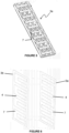
- the battery pack assembly 1 comprises a plurality of lithium-ion cells 2, each cell being held longitudinally between two holding frames 3.
- the generally rectangular holding frames 3 (which may be made of a plastic material for example) each comprise a generally flat base 4, side walls 5 extending generally perpendicularly from the base 4, elastomeric members 6, conductive plates 7, screw slots 8 and battery terminals 9.
- the holding frames 3 are reversibly held together by fastening screws 10, with the plurality of cells 2 held in place between the holding frames 3 by the compressive force of the fastening screws 10, which each thread through a screw slot 8 in each of the two holding frames 3.
- the side walls 5 of the holding frame 3 each comprise a plurality of concave arcuate side wall sections 11.
- a plurality of base protrusions 12 also extend perpendicularly from the base 4.
- the side walls of the base protrusions 12 may comprise a plurality of concave arcuate protrusion wall sections 13.
- Each concave arcuate side wall section 11 in combination with at least one concave arcuate protrusion wall section 13 thereby defines part of a generally cylindrical region 14 to seat a cylindrical cell 2.
- the screw slots 8 for the receiving of the fastening screws 10 are positioned in some of the base protrusions 12.
- the base 4 further comprises a plurality of recesses 15, in each of which may sit an elastomeric member 6 forming an elastomeric protrusion. This may be of rubber, a rubber compound, a plastics material and so on.
- the protrusions may be otherwise shaped to accommodate other cell shapes, eg generally planar intersections or square to accommodate rectangular or square cells. In the past the cells may be of any desired shape.
- Figure 3 shows the holding frame of Figure 3 , wherein each of the recesses 15 is fitted with an elastomeric member 6.
- Figure 4 shows one possible arrangement of the conductive plates 7 to be inserted into a holding frame 3a.
- three cells would be electrically connected by each of the two linear conductive plates 7a, and six cells would be electrically connected by each of the four U-shaped conductive plates 7b.
- An opposing holding frame 3b (not shown) will be associated with an arrangement of conductive plates 7 complementary to the arrangement of conductive plates 7 inserted into the holding frame 3a, such that all of the plurality of cells 2 are electrically connected in a desired arrangement, for example in series, in parallel, or in series-parallel (i.e. wherein one set of cells in parallel are connected in series with one or more further sets of cells also in parallel).
- the end plates 7a each have projections 16 which connect with the battery terminals 9 on one of the holding frames 3, to enable the plurality of cells 2 to be connected to an external circuit.
- Figure 5 shows the holding frame 3a in combination with conductive plates 7 of Figure 4 .
- the conductive plates 7 are positioned across the base 4 of the holding frame 3a and are positioned to extend across a plurality of generally cylindrical regions 14, so as to electrically connect a plurality of cells 2 when the plurality of cells 2 are each positioned within a respective generally cylindrical region 14 and held between the holding frames 3.
- the compression caused by the tightening of the fastening screws 10 encourages contact between the plurality of cells 2 and the conductive plates 7, wherein the conductive plates 7 are further urged towards the plurality of cells 2 by the elastomeric members 6 urging the conductive plates 7 upwardly, ensuring robust electrical contacts.
- Figure 6 shows one example of how the conductive plates 7 may be positioned across the bases 4 of each of the two holding frames 3a and 3b to form a complete circuit (once the plurality of cells 2 are inserted and compressed by the fastening means).
- Each of the plurality of cells 2 must be orientated such that the polarity of each cell 2 opposes the polarity of the adjacent cell in the series (for example, the first cell in the series is positioned with the positive terminal positioned towards holding frame 3a, the second cell in the series is positioned with the positive terminal positioned towards holding frame 3b, and so on).
- terminals 9 on the holding frame 3 connecting to tabs 16 of the conductive plates 7
- other connecting means may be provided to connect the arrangement of batteries to an external circuit.
- Conductive means and/or elastomeric protrusions may be necessary just on one side of a cell array in some embodiments.
- one of the holding frames may be an access lid. This can be removed or perhaps opened to enable access to cells within, for replacement or maintenance of the cells.
- the access lid may have conductive means and perhaps also elastomeric portions or may in other embodiments not be provided with these, in which case the electrical connections are all made at the side of the cells distal from the access lid.
- FIG. 7 shows an embodiment of a section of a battery pack assembly 71 according to the invention.
- the battery pack assembly 71 comprises a plurality of cells 72 (only one shown), a pair of holding frames 73 (only one shown), a conductive plate 74, and a conduction breaking means or conduction breaker 75.
- the conduction breaker 75 comprises a first conductive portion 76a, a second conductive portion 76b, an insulating portion or body 77, and a conduction breaker 78.
- the first conductive portion 76a makes contact with a terminal of the cell 72.
- the second conductive portion 76b makes contact with the conductive plate 74.
- the conduction breaker 78 is positioned between the first conductive portion 76a and the second conductive portion 76b, within the insulating portion 77.
- the first conductive portion 76a, the conduction breaker 78, and the second conductive portion 78b are electrically connected. In use, electrical current flows from the cell 72, through the first conductive portion 76a, the conduction breaker 78, and the second conductive portion 78b, to the conductive plate 74. If the electrical or thermal limit of the conduction breaker 78 is exceeded, then the conduction breaker 78 will break the electrical circuit between a cell 72 and the conductive plate 74.
- FIG 8 shows an exploded view of an embodiment of a prismatic cell battery pack assembly 81.
- the prismatic cell battery pack assembly 81 comprises a number of cells 82a, 82b, 82c...82z (where the total number of cells is chosen by design requirements), a top holding frame 83a, a base holding frame 83b, a first conductive plate 84a, a second conductive plate 84b, and a set of elastomeric protrusions 85a.
- the cells 82a-82z each comprise a respective cell terminal 86a-86z.
- the set of elastomeric protrusions 85a are positioned between the holding frame 83a and the conductive plate 84a.
- FIG 12 shows an embodiment of the battery pack assembly 120.
- the battery pack 120 comprises a first holding frame 121, a second holding frame 122, a third holding frame 123, a first set of cells 124A, and a second set of cells 124B.
- the second holding frame 122 has a first side 122A and a second side 122B.
- the holding frames 100 or 110 of Figures 10 and 11 may be used in this embodiment as the first, second, or third holding frames 121, 122, 123.
- the first set of cells 124A are accommodated in recesses (not shown) provided in the first holding frame 121 and recesses (not shown) provided in the first side 122A of the second holding frame 122.
- the number of cells used in the first set of cells 124A or the second set of cells 124B is not limited to that shown in Figure 12 , and may be selected as appropriate for the application.
Landscapes
- Chemical & Material Sciences (AREA)
- Chemical Kinetics & Catalysis (AREA)
- Electrochemistry (AREA)
- General Chemical & Material Sciences (AREA)
- Engineering & Computer Science (AREA)
- Manufacturing & Machinery (AREA)
- Battery Mounting, Suspending (AREA)
Description
- The present invention relates to a battery pack assembly. Particularly, but not exclusively, the present invention relates to a lithium-ion battery pack assembly, and particularly to a large format battery pack assembly for example, for use with an electric vehicle such as an electric bike.
- Lithium-ion batteries are known in a variety of cell formats, cylindrical, prismatic and pouch cells are the most common varieties. In a cylindrical cell the electrode is tightly wound about itself and the terminals are typically found at either end of the cylinder, the electrode being contained within a casing, typically made from aluminium. Due to the shape of the cell packing efficiency may be low but the provision of spaces between adjacent cells is useful for thermal management purposes. The electrodes of prismatic cells can be wound, stacked or folded and are usually located within an aluminium or plastics housing. The terminals are often on one end of the cell which, coupled with the shape of the cell improves packing efficiency. Pouch cells typically have stacked or folded electrodes encased in a flexible plastics casing. The terminals of pouch cells may extend from different sides of the pouch but conveniently they may both extend from one side, for example the top, of the pouch.
- In order to increase the power delivery from cells it is known to connect them in series. A number of cells connected in series may be termed a 'large format battery pack'. There appears to be no set definition of what constitutes a 'large format'. The UN, for example (e.g. in relation to the UN38.3 Procedure), states that a 'large battery' is one that has a mass in excess of 12 kg whereas some manufacturers specify that large batteries or large format battery packs have a power in excess of 1kWh. For the purposes of this invention we consider that a large format battery pack is one with more than three cells (be they cylindrical, prismatic or pouch) connected in series.
- Large format battery packs using cylindrical cells often have a plurality of cells, typically 15 or more cells, electrically connected and presented as a single unit called a battery module. In industry, these modules are typically assembled using permanent assembly techniques (structural adhesives, soldering etc.). Such permanent assembly techniques present challenges for repairing or reusing the modules (or the cells or other parts thereof), as the individual components of the assembly cannot easily be accessed or removed. This also makes it difficult to recycle the modules, as the various materials cannot easily be separated.
- Accordingly, such production techniques can lead to energy storage products which are not aligned with EU waste management legislations and prohibits greater revenue opportunities in the repair and repurposing of batteries and battery modules.
-
JP2008204986 EP3053205 discloses an electrical battery module comprising a casing comprising a longitudinal body suitable for longitudinally receiving a plurality of electrical batteries, one next to the other, and an end cover coupled to one of the ends of said longitudinal body.WO2012082691 discloses a battery integration module which includes a first positioning plate for positioning multiple single batteries in formation for integration at one end of the battery formation, a second positioning plate for positioning the multiple single batteries in formation for integration at the opposite end of the battery formation, the first and second plates aligned together over the formation of batteries to form a battery holder frame. - The present invention arose in an attempt to provide a more readily recyclable battery pack assembly.
- According to the present invention there is provided a battery pack assembly comprising two holding frames, wherein the two holding frames hold a plurality of cells between them, wherein at least two cells of the plurality of cells are connected by a conductor, and wherein the two holding frames are reversibly held with respect to one another in a closed condition by a fastening means or fastener, wherein the fastening means or fastener cause terminals of the two cells to be urged against the conductor and removal or loosening of the fastener or fastening means enables the cells to be freed from the assembly, at least one holding frame comprising one or more elastomeric protrusions and wherein the conductor is positioned such that at least a part of the conductor lies between one or more of the elastomeric protrusions and one or more cell terminals, such that with the frames in the closed condition the conductor is urged into contact by the elastomeric protrusions with said one or more terminals.
- The present invention allows for the complete disassembly of a large format battery pack assembly into its individual components. The ability to completely disassemble the assembly permits the module to be repaired via the replacement of individual cells or other components, allows individual components of the module to be reused for further applications at the end of the useful life of the complete assembly, and allows for improved recycling as each of the individual components of the module can be separated and sorted for recycling accordingly.
- As well as assisting manufacturers to meet EU waste management legislation, the ability to reuse, repair and recycle individual components of battery modules would also save money and resources for the manufacturers. Individual or multiple cells may be replaced with ease, meaning the assemblies could be repeatedly rebuilt at end of life instead of being disposed. It also presents the opportunity for the reuse of cells from a module in other energy storage applications when they no longer perform in the original module application or when the module is no longer required.
- Preferably the two holding frames are reversibly held together by the fastener or fastening means.
- The conductor preferably connects the two cells in series.
- In a further or more specific aspect of the invention there is provided a battery pack assembly comprising two holding frames, wherein the two holding frames hold a plurality of cells between them, each cell being held longitudinally between the two holding frames, wherein two or more of the plurality of cells are connected by a conductive means, and wherein the two holding frames are reversibly held together by a fastening means, wherein the fastening means cause terminals of the cells to be urged against the conductive means and removal or loosening of the fastening means enables the cells to be freed from the assembly, at least one holding frame comprising one or more elastomeric protrusions and wherein the conductive means are positioned such that parts of them lie between one or more elastomeric protrusions and one or more cell terminals, such that the urging of the frames together by the fastening means causes the conductive means to be urged into contact by the elastomeric protrusions with said one or more terminals.
- In one embodiment of the present invention, the assembly consists of a set of cells positioned between two parallel holding frames, each cell being held longitudinally or laterally between the two holding frames by virtue of the fastening means being secured or 'tightened' to clamp the cells between the holding frames.
- One of the frames may be or may provide an access lid, which can be opened or removed to gain access to the cells.
- Each holding frame may comprise a generally flat base and side walls. If the holding frame is to be used with cylindrical cells at least one side wall, and preferably facing side walls, may further comprise a one or more concave arcuate sections complementary to the side wall of the cells to be inserted into the assembly. The holding frames may further comprise a plurality of protrusions extending perpendicularly from the base, for example to delimit or space the adjacent portions of the cells from one another. For example, the walls of the base protrusions may comprise a plurality of concave arcuate sections complementary to the facing portions of the cells to be inserted into the assembly.
- The holding frame/access lid may be shaped to accommodate cells of different shapes than cylindrical ones, e.g. rectangular or other shapes.
- Where cylindrical cells are deployed, each holding frame may therefore define a plurality of whole or part generally cylindrical regions, each defined by a concave arcuate side wall section and at least one concave arcuate base protrusion wall section, wherein each generally cylindrical region may seat a cylindrical cell.
- For cylindrical cells, the conductor(s) or conductive means (e.g. one or more conductive plates) may be positioned laterally across the base of each holding frame and may lie across the multiple whole or part generally cylindrical regions (i.e. to bridge them) so as to electrically connect multiple cells seated therein. The conductive plates may be any shape which would cover more than one generally cylindrical region, such as linear, U-shaped, S-shaped, L-shaped, T-shaped, H-shaped, etc. The gaps in the walls of the generally cylindrical regions allow for the insertion of conductive plates in various arrangements; changing the arrangement of the conductive plates adapts the battery module for various applications using the same holding frame. Conductive plates may be provided on both holding frames, the arrangement of the conductive plates in each of the two holding frames preferably being complementary, such that they form a complete circuit when the plurality of cells are held within the two holding frames, electrically connecting all of the cells in the assembly in series. For example, the cells may be arranged with neighbouring cells alternatively positioned with the positive terminal upwards and the positive terminal downwards respectively, and the positive and negative terminals on each side being connected together, so that a complete circuit is formed. Means are provided to connect the appropriate conductive plates to external means for driving a vehicle or other equipment, control/processing means and so on. There may be electrical terminals connected to some of the conductive plates.
- The two holding frames are held together by a fastener or fastening means, which may consist of a plurality of fastening screws. Each fastening screw may each thread through a hole in each of the two holding frame and act to compress the assembly, encouraging contact between the cells and the conductive means. The threaded holes in each of the holding frames may be positioned in the holding frame base protrusions.
- In embodiments, the frame - cell - frame (FCF) architecture can be repeated plural times to form an FCFCF architecture, or FCFCF....CF architecture. In such a case the 'end' frames, being those at the terminal edges of the battery pack, may have portions to receive the facing cell or cells whereas the 'intermediate' frames, being those between the end frames, may have a first side having portions to receive the facing cell or cells and a second side having portions to receive the facing cell or cells.
- In embodiments, the battery pack assembly comprises one or more conduction breaking means or conduction breaker. A conduction breaking means or conduction breaker may be positioned between each cell terminal, and the conductor or conductive means, which may be a conductive plate. Preferably, a conduction breaking means or conduction breaker is provided between every cell terminal and the associated conductor or conductive means. The purpose of the one or more conduction breaking means of conduction breaker is to break the electrical circuit between a cell and the conductor or conductive means, when said cell exceeds a prescribed electrical and/or thermal limit. Upon exceeding a prescribed electrical and/or thermal limit, the conduction breaking means of conduction breaker severs the connection of the failed cell, i.e. a cell that has exceeded a prescribed electrical and/or thermal limit, isolating said failed cell from the rest of the battery pack assembly.
- The conduction breaking means or conduction breaker may comprise a first conductive portion for making contact with the cell terminal, a second conductive portion for making contact with the conductor or conductive means, an insulating portion, and a conduction breaker portion. The conduction breaking means or conduction breaker may comprise a metallic alloy, or a multi-metallic element and may comprise a bimetal fuse. The conduction breaker portion may comprise a low melting material, for example, a metal such as silver, or silver plated copper, tin, or zinc, or alloys of the same, which melts upon exceeding the electrical and/or thermal limit determined by the melting point of the material.
- Advantageously, the contact between the conduction breaking means or conduction breaker with both the conductive means one on major surface, and the cell terminal on the opposite major surface, is increased upon 'tightening' of the fastening means when the battery pack assembly is under compression. More advantageously, the one or more conduction breaking means or conduction breaker allow the battery pack assembly to continue to function upon failure of an individual cell, by isolating the one or more failed cells from the other functioning cells in the battery pack assembly.
- The elastomeric protrusions are preferably positioned generally where the terminals of one or more cells lie when the cells are seated within the holding frames. The conductive means may be positioned such that parts of them lie between the elastomeric protrusions and one or more cell terminals, such that the elastomeric protrusions act to further encourage contact between the one or more cell terminals and the conductive means when the assembly is under compression from the 'tightening' of the fastening means. This ensures quality electrical contacts are maintained even when the assembly undergoes vibration.
- In embodiments, the battery pack assembly comprises a monitoring means or monitor for monitoring the status of each cell. The monitoring means may comprise an integrated electrical circuit, which monitors the status of each cell by detecting the number of triggered conduction breaking means or conduction breakers resulting from failed cells, i.e. a cell that has exceeded a prescribed electrical and/or thermal limit, within the battery pack assembly. The monitoring means may comprise a method of determining the condition of the battery pack assembly. For example, the monitoring means may transmit data, which has been collected about the status of each cell within the assembly, to be fed through an algorithm to compare with the optimal function of the assembly, to determine the number of fully functioning cells and the number of failed cells. Advantageously, this provides information on the overall condition and remaining useful life of the battery pack assembly. More advantageously, this information may be used to inform the user of maintenance requirements, and of potential safety hazards from using an under-performing battery pack assembly.
- The battery pack assembly may be any format including laminates, pouch, cylindrical, and/or prismatic.
- The design of the assembly also allows for the integration of liquid cooling for high power applications.
- Embodiments of the present invention will now be described, by way of example only, with reference to the accompanying figures, in which:
-
Figure 1 shows a partially exploded view of a battery pack assembly according to the invention; -
Figure 2 shows a holding frame according to the invention; -
Figure 3 shows the holding frame ofFigure 2 with the elastomeric members inserted; -
Figure 4 shows an arrangement of conductive plates; -
Figure 5 shows the conductive plates ofFigure 4 inserted into the holding frame ofFigure 2 or3 ; -
Figure 6 shows two holding frames, each with conductive plates inserted, to form a complete circuit once the plurality of cells are inserted; -
Figure 7 shows an embodiment of a section of a battery pack assembly comprising a conduction breaking means; -
Figure 8 shows an embodiment of a second battery pack assembly according to the invention; -
Figure 9 shows an embodiment of a third battery pack assembly according to the invention; -
Figure 10 shows an example of a holding frame according to the invention; -
Figure 11 shows a second example of a holding frame according to the invention; and -
Figure 12 shows an embodiment of a fourth battery pack assembly according to the invention. - Referring to
Figure 1 , a first embodiment of abattery pack assembly 1 is shown. Thebattery pack assembly 1 comprises a plurality of lithium-ion cells 2, each cell being held longitudinally between two holdingframes 3. The generally rectangular holding frames 3 (which may be made of a plastic material for example) each comprise a generallyflat base 4,side walls 5 extending generally perpendicularly from thebase 4,elastomeric members 6,conductive plates 7,screw slots 8 and battery terminals 9. The holding frames 3 are reversibly held together by fasteningscrews 10, with the plurality ofcells 2 held in place between the holdingframes 3 by the compressive force of the fastening screws 10, which each thread through ascrew slot 8 in each of the two holding frames 3. - Referring to
Figure 2 , one embodiment of a holdingframe 3 is shown. Theside walls 5 of the holdingframe 3 each comprise a plurality of concave arcuateside wall sections 11. A plurality ofbase protrusions 12 also extend perpendicularly from thebase 4. The side walls of thebase protrusions 12 may comprise a plurality of concave arcuateprotrusion wall sections 13. Each concave arcuateside wall section 11 in combination with at least one concave arcuateprotrusion wall section 13 thereby defines part of a generallycylindrical region 14 to seat acylindrical cell 2. Thescrew slots 8 for the receiving of the fastening screws 10 are positioned in some of the base protrusions 12. Thebase 4 further comprises a plurality ofrecesses 15, in each of which may sit anelastomeric member 6 forming an elastomeric protrusion. This may be of rubber, a rubber compound, a plastics material and so on. - Instead of actuate sections, for accommodating generally cylindrical cells, the protrusions may be otherwise shaped to accommodate other cell shapes, eg generally planar intersections or square to accommodate rectangular or square cells. In the past the cells may be of any desired shape.
-
Figure 3 shows the holding frame ofFigure 3 , wherein each of therecesses 15 is fitted with anelastomeric member 6. -
Figure 4 shows one possible arrangement of theconductive plates 7 to be inserted into a holdingframe 3a. In this example, three cells would be electrically connected by each of the two linearconductive plates 7a, and six cells would be electrically connected by each of the four U-shapedconductive plates 7b. An opposing holdingframe 3b (not shown) will be associated with an arrangement ofconductive plates 7 complementary to the arrangement ofconductive plates 7 inserted into the holdingframe 3a, such that all of the plurality ofcells 2 are electrically connected in a desired arrangement, for example in series, in parallel, or in series-parallel (i.e. wherein one set of cells in parallel are connected in series with one or more further sets of cells also in parallel). Theend plates 7a each haveprojections 16 which connect with the battery terminals 9 on one of the holding frames 3, to enable the plurality ofcells 2 to be connected to an external circuit. -
Figure 5 shows the holdingframe 3a in combination withconductive plates 7 ofFigure 4 . Theconductive plates 7 are positioned across thebase 4 of the holdingframe 3a and are positioned to extend across a plurality of generallycylindrical regions 14, so as to electrically connect a plurality ofcells 2 when the plurality ofcells 2 are each positioned within a respective generallycylindrical region 14 and held between the holding frames 3. The compression caused by the tightening of the fastening screws 10 encourages contact between the plurality ofcells 2 and theconductive plates 7, wherein theconductive plates 7 are further urged towards the plurality ofcells 2 by theelastomeric members 6 urging theconductive plates 7 upwardly, ensuring robust electrical contacts. -
Figure 6 shows one example of how theconductive plates 7 may be positioned across thebases 4 of each of the two holdingframes cells 2 are inserted and compressed by the fastening means). Each of the plurality ofcells 2 must be orientated such that the polarity of eachcell 2 opposes the polarity of the adjacent cell in the series (for example, the first cell in the series is positioned with the positive terminal positioned towards holdingframe 3a, the second cell in the series is positioned with the positive terminal positioned towards holdingframe 3b, and so on). - Instead of screws (and threaded holes into which the screws are located), other fastening means which can be tightened to clamp or urge the plates towards each other may be provided.
- Instead of terminals 9 on the holding
frame 3 connecting totabs 16 of theconductive plates 7, other connecting means may be provided to connect the arrangement of batteries to an external circuit. This includes, but is not limited to, an arrangement wherein the external circuit connects directly to the conductive means, an arrangement wherein the two terminals 9 are not positioned on thesame holding frame 3, or an arrangement wherein there are more than two terminals 9 to allow more than one circuit to be independently connected to the module, wherein the conductive means arrangement can be varied to select howmany cells 2 are connected to each of the connected circuits respectively. - Conductive means and/or elastomeric protrusions may be necessary just on one side of a cell array in some embodiments.
- In embodiments one of the holding frames (generally an upper most one) may be an access lid. This can be removed or perhaps opened to enable access to cells within, for replacement or maintenance of the cells. The access lid may have conductive means and perhaps also elastomeric portions or may in other embodiments not be provided with these, in which case the electrical connections are all made at the side of the cells distal from the access lid.
-
Figure 7 shows an embodiment of a section of abattery pack assembly 71 according to the invention. Thebattery pack assembly 71 comprises a plurality of cells 72 (only one shown), a pair of holding frames 73 (only one shown), aconductive plate 74, and a conduction breaking means orconduction breaker 75. Theconduction breaker 75 comprises a firstconductive portion 76a, a secondconductive portion 76b, an insulating portion orbody 77, and aconduction breaker 78. The firstconductive portion 76a makes contact with a terminal of thecell 72. The secondconductive portion 76b makes contact with theconductive plate 74. Theconduction breaker 78 is positioned between the firstconductive portion 76a and the secondconductive portion 76b, within the insulatingportion 77. The firstconductive portion 76a, theconduction breaker 78, and the second conductive portion 78b are electrically connected. In use, electrical current flows from thecell 72, through the firstconductive portion 76a, theconduction breaker 78, and the second conductive portion 78b, to theconductive plate 74. If the electrical or thermal limit of theconduction breaker 78 is exceeded, then theconduction breaker 78 will break the electrical circuit between acell 72 and theconductive plate 74. Theconduction breaker 75 severs the conduction of the failedcell 72 from thebattery pack assembly 71 so that it may continue to function with the remaining functional cells (not shown). In prior art cell designs the conduction breakers are spot-welded to the cells and/or the conductive plates to make a robust and effective electrical connection. Advantageously, because of the plurality of elastomeric projections theconductive portions conduction breaker 75 are urged into intimate contact with the respective connection of the battery pack assembly, thereby providing additional safety performance without compromising the ease of assembly/disassembly of the battery pack. -
Figure 8 shows an exploded view of an embodiment of a prismatic cellbattery pack assembly 81. The prismatic cellbattery pack assembly 81 comprises a number ofcells top holding frame 83a, abase holding frame 83b, a firstconductive plate 84a, a secondconductive plate 84b, and a set ofelastomeric protrusions 85a. Thecells 82a-82z each comprise arespective cell terminal 86a-86z. The set ofelastomeric protrusions 85a are positioned between the holdingframe 83a and theconductive plate 84a. In use, the set ofelastomeric protrusions 85a are in contact with the holdingframe 83a and theconductive plate 84a. The firstconductive plate 84a provides an electrical connection between thecell terminals conductive plate 84b provides an electrical connection between thecell terminals 86c and a successive cell, and so on. Thebattery pack assembly 81 may be fastened together with fastening means (not shown), which urges together the holdingframe 83a, the set ofelastomeric protrusions 85a, theconducive plate 84a, and thecell terminal 86a to provide solid contact between thecell terminal 86a and theconductive plate 84a. Advantageously, the prismaticcell battery pack 81 may be disassembled into its constituent parts when not in use, or for repair or reuse. -
Figure 9 shows an exploded view of an embodiment of a pouch cellbattery pack assembly 91. The pouch cellbattery pack assembly 91 comprises a number ofcells conductive plates elastomeric protrusions anode cell terminals elastomeric protrusions 95a-95z are positioned between the respectiveconductive plates 94a-94z and the respectiveanode cell terminals 96a-96z. Another set of elastomeric protrusions (not shown) are positioned between theconductive plates 94a-94z and the respective cathode cell terminals 97a-97c (not shown) and 97z. Theconductive plates 94a-94z are in electrical contact with the respectiveanode cell terminals 96a-96z, and the cathode cell terminals (97a, 97b, 97c are not shown) and 97z. For example, theelastomeric protrusion 95a is positioned between one face ofconductive plate 94a and one face of thecell terminal 96a ofcell 92a. In use, one or more elastomeric protrusions, for example, elastomeric protrusion 95d may be provided on a holdingframe battery pack assembly 91 may be fastened together with fastening means (not shown), which urges together the holdingframe elastomeric protrusions 95a-95z, theconducive plates 94a-94z, and thecell terminals 96a-96z to provide solid contact between thecell terminal 96a-96z and the respectiveconductive plates 94a-94z. Advantageously, the prismaticcell battery pack 91 may be disassembled into its constituent parts when not in use. -
Figure 10 shows a second example of a holdingframe 100 according to the invention. The holdingframe 100 comprises a plurality of recesses orrebates 101. The recesses orrebates 101 are linearly arranged in asquare configuration 102. -
Figure 11 shows a third example of a holdingframe 110 according to the invention. The holdingframe 110 comprises a plurality of recesses orrebates 111. Therecesses 111 are linearly arranged in ahexagonal configuration 112. - The
recesses Figure 10 and Figure 11 may be any shape that will accommodate a cell (not shown) when the battery pack of the present invention is assembled. In use, elastomeric protrusions (not shown) are provided within therecesses frame -
Figure 12 shows an embodiment of thebattery pack assembly 120. Thebattery pack 120 comprises afirst holding frame 121, asecond holding frame 122, athird holding frame 123, a first set ofcells 124A, and a second set ofcells 124B. Thesecond holding frame 122 has afirst side 122A and asecond side 122B. The holding frames 100 or 110 ofFigures 10 and 11 may be used in this embodiment as the first, second, or third holding frames 121, 122, 123. The first set ofcells 124A are accommodated in recesses (not shown) provided in thefirst holding frame 121 and recesses (not shown) provided in thefirst side 122A of thesecond holding frame 122. The second set ofcells 124B are accommodated in recesses (not shown) provided in thesecond side 122B of thesecond holding frame 122, and recesses (not shown) provided in thethird holding frame 123. The recesses (not shown) may be of theconfigurations Figures 10 and 11 . Thesecond holding frame 122 may possess recesses on both thefirst side 122A and thesecond side 122B of thesecond holding frame 122. Alternatively, thesecond holding frame 122 may comprise two separate holding frames that are secured together, which possess recesses (not shown) on opposing sides (i.e. thefirst side 122A and thesecond side 122B) to accommodate the first set ofcells 124A and the second set ofcells 124B. - The recess configuration (not shown) of the holding frames 121, 122, 123 is selected to accommodate the shape of the first set of
cells 124A and the second set ofcells 124B and be complementary to the opposing holding frame. For example, the recess configuration (not shown) of thefirst holding frame 121 is selected to be complementary to the recess configuration (not shown) of thefirst side 122A of thesecond holding frame 122, to accommodate the first set ofcells 124A. - The number of cells used in the first set of
cells 124A or the second set ofcells 124B is not limited to that shown inFigure 12 , and may be selected as appropriate for the application. - In each of the above embodiments the battery pack assembly of the invention may comprise a monitoring means or monitor for monitoring the status of each cell. The monitoring means may comprise an integrated electrical circuit, which monitors the status of each cell by detecting the number of triggered conduction breaking means or conduction breakers resulting from failed cells, i.e. a cell that has exceeded a prescribed electrical and/or thermal limit, within the battery pack assembly. The monitoring means may transmit data, which has been collected about the status of each cell within the assembly, to be fed through an algorithm to compare with the optimal function of the assembly, to determine the number of fully functioning cells and the number of failed cells. Advantageously, this provides information on the overall condition and remaining useful life of the battery pack assembly. More advantageously, this information may be used to inform the user of maintenance requirements, and of potential safety hazards from using an under-performing battery pack assembly.
- The above embodiments of the present invention have been described by way of example only and it will be apparent to those skilled in the art that modifications may be made without departing from the scope of the appended claims.
- The drawings then show, in a broad aspect, a battery back assembly comprising two holding frames, wherein the two holding frames hold a plurality of cells between them, each cell being held longitudinally between the two holding frames, wherein two or more of the plurality of cells are connected by a conductive means, and wherein the two holding frames are reversibly held together by a fastening means, wherein the fastening means cause terminals of the cells to be urged against the conductive means and removal or loosening of the fastening means enables the cells to be freed from the assembly.
Claims (15)
- A battery pack assembly (1) comprising two holding frames (3), wherein the two holding frames (3) hold a plurality of cells (2) between them, wherein at least two cells of the plurality of cells (2) are connected by a conductor (7), and wherein the two holding frames (3) are reversibly held with respect to one another in a closed condition by a fastening means or fastener (10), wherein the fastening means or fastener (10) cause terminals of the two cells (2) to be urged against the conductor (7) and removal or loosening of the fastener or fastening means (10) enables the cells (2) to be freed from the assembly (1), at least one holding frame (3) comprising one or more elastomeric protrusions (6) and characterized in that the conductor (7) is positioned such that at least a part of the conductor (7) lies between one or more of the elastomeric protrusions (6) and one or more cell terminals (9), such that with the frames (3) in the closed condition the conductor (7) is urged into contact by the elastomeric protrusions (6) with said one or more terminals (9).
- A battery pack assembly (1) according to Claim 1, wherein the conductor (7) connects the two cells (2) in series.
- A battery pack assembly (1) according to Claim 1 or 2, wherein the plurality set of cells (2) are positioned between two parallel holding frames (3), each cell (2) being held longitudinally or laterally between the two holding frames (3) by virtue of the fastener or fastening means (10).
- A battery pack assembly (1) according to any preceding Claim, wherein one of the frames (3) is or provides an access lid, which can be opened or removed to gain access to the cells (2).
- A battery pack assembly (1) as claimed in any preceding claim, wherein at least one holding frame (3) comprises one or more terminals (9) for connection to an external electrical circuit.
- A battery pack assembly (1) as claimed in any preceding claim, wherein the conductor or conductive means (7) comprises one or more conductive plates.
- A battery pack assembly as claimed in Claim 6, wherein one or more of the conductive plates (7) comprise means to provide a means for connecting the conductive plates (7) to an external circuit, said means for connecting the conductive plates (7) to the external circuit may comprise at least one conductive plate projection.
- A battery pack assembly (1) as claimed in any preceding claim, wherein at least one holding frame (3) comprises a base (4) and side walls (5), wherein base protrusions (12) extend perpendicularly from the base (4).
- A battery pack assembly (1) as claimed in Claim 8, wherein the walls of the one or more base protrusions (12) comprise a plurality of concave arcuate sections (13), and wherein each concave arcuate protrusion wall section (13) may have a radius of curvature generally equal to the radius of one of the plurality of cells (2), so that a cell (2) is at least partially received by the concave arcuate section (13).
- A battery pack assembly (1) as claimed in Claim 8 or 9, wherein at least one of the holding frame side walls (5) each comprise a plurality of concave arcuate sections (11).
- A battery pack assembly (1) as claimed in Claim 10, wherein the cells (2) are generally cylindrical, and the plurality of concave arcuate sections (11) each have a radius of curvature substantially equal to the radius of one of the plurality of cells (2), so that a cell (2) is at least partially received by the concave arcuate section (11).
- A battery pack assembly (1) as claimed in Claim 11 when dependent on any of Claim 8, 9 or 10, wherein the one or more base protrusions (12) are positioned such that the concave arcuate side wall sections (11) and the concave arcuate protrusion wall sections (13) define at least part of a plurality of generally cylindrical regions (14) to each seat a cylindrical cell (2), each elastomeric protrusion (6) may be positioned centrally in a generally cylindrical region (14).
- A battery pack assembly (1) as claimed in any preceding claim, wherein the fastening means (10) comprises a plurality of fastening screws, each holding frame (3) may comprise a plurality of threaded holes through which each fastening screw may be threaded and each of the threaded holes may be positioned in a base protrusion.
- A battery pack assembly (1, 71) according to any preceding Claim, further comprising one or more frictionally retained conduction breakers (75), wherein the or each conduction breaker (75) may be positioned between a cell terminal (72), and the conductor or conductive means (74).
- A battery pack assembly (1, 71) according to Claim 14, wherein the or each conduction breaker (75) comprises a first conductive portion (76a) for making contact with the cell terminal (72), a second conductive portion (76b) for making contact with the conductor or conductive means (74), an insulating portion (77), and a conduction breaker portion (78), the conduction breaker portion (78) may comprise a low melting material, for example, a metal such as silver, or silver plated copper, tin, or zinc, or alloys of the same, which melts upon exceeding the electrical and/or thermal limit determined by the melting point of the material or a bi metal fuse.
Applications Claiming Priority (1)
| Application Number | Priority Date | Filing Date | Title |
|---|---|---|---|
| PCT/GB2017/051433 WO2018215725A1 (en) | 2017-05-23 | 2017-05-23 | Battery pack assembly |
Publications (3)
| Publication Number | Publication Date |
|---|---|
| EP3631876A1 EP3631876A1 (en) | 2020-04-08 |
| EP3631876B1 true EP3631876B1 (en) | 2025-04-16 |
| EP3631876C0 EP3631876C0 (en) | 2025-04-16 |
Family
ID=58772597
Family Applications (1)
| Application Number | Title | Priority Date | Filing Date |
|---|---|---|---|
| EP17725762.3A Active EP3631876B1 (en) | 2017-05-23 | 2017-05-23 | Battery pack assembly |
Country Status (4)
| Country | Link |
|---|---|
| US (3) | US11469466B2 (en) |
| EP (1) | EP3631876B1 (en) |
| CN (1) | CN110663122A (en) |
| WO (1) | WO2018215725A1 (en) |
Families Citing this family (8)
| Publication number | Priority date | Publication date | Assignee | Title |
|---|---|---|---|---|
| US11469466B2 (en) | 2017-05-23 | 2022-10-11 | Aceleron Limited | Battery pack assembly |
| GB201821086D0 (en) * | 2018-12-21 | 2019-02-06 | Aceleron Ltd | Battery pack assembly |
| DE102019131200A1 (en) * | 2019-11-19 | 2021-05-20 | Bayerische Motoren Werke Aktiengesellschaft | Power-free battery module for a traction battery, method for producing a battery module, traction battery and electrically drivable motor vehicle |
| AT523340B1 (en) * | 2020-01-09 | 2022-12-15 | Miba Battery Systems Gmbh | clamping device |
| EP4100277B1 (en) * | 2020-02-04 | 2024-05-29 | Volvo Penta Corporation | Vehicular energy storage module, battery pack and vehicle |
| KR102882948B1 (en) * | 2020-08-07 | 2025-11-07 | 주식회사 엘지에너지솔루션 | Battery pack having current interrupt apparatus using bi-metal, and operation method thereof |
| GB2605787B (en) | 2021-04-12 | 2024-10-16 | Upgrade Tech Engineering Ltd | A battery cell holder |
| KR102853689B1 (en) * | 2025-01-22 | 2025-09-02 | 주식회사 오빌 | Battery module with enhanced electric connection stability of battery cells |
Citations (1)
| Publication number | Priority date | Publication date | Assignee | Title |
|---|---|---|---|---|
| US20100304201A1 (en) * | 2007-05-15 | 2010-12-02 | Olivier Caumont | Module for electric energy storage assemblies for ageing detection of said assemblies |
Family Cites Families (24)
| Publication number | Priority date | Publication date | Assignee | Title |
|---|---|---|---|---|
| JP4610362B2 (en) | 2005-02-04 | 2011-01-12 | 三洋電機株式会社 | Pack battery |
| JP5162919B2 (en) * | 2007-02-16 | 2013-03-13 | パナソニック株式会社 | Power storage unit |
| FR2920913B1 (en) | 2007-09-06 | 2009-11-13 | Pellenc Sa | BATTERY CONSISTING OF A PLURALITY OF CELLS POSITIONED AND CONNECTED BETWEEN THEM, WITHOUT WELDING. |
| JP4960839B2 (en) * | 2007-11-12 | 2012-06-27 | 本田技研工業株式会社 | Battery cooling device for vehicle |
| KR101016596B1 (en) | 2009-01-29 | 2011-02-22 | 강정욱 | Cell cartridge consisting of intercell interconnection |
| AT508742B1 (en) * | 2009-09-10 | 2011-07-15 | Norman Neuhold | INSERT FOR AN ACCUMULATOR PART |
| KR101097258B1 (en) | 2009-12-04 | 2011-12-21 | 삼성에스디아이 주식회사 | Battery pack |
| US9184430B2 (en) * | 2010-12-13 | 2015-11-10 | Andrew E. Kalman | Battery pack for integrating multiple single batteries |
| AU2012373356B2 (en) | 2012-03-12 | 2016-02-25 | Chung Peng Liew | Non-welded battery module |
| CN202503048U (en) | 2012-04-01 | 2012-10-24 | 山东精工电子科技有限公司 | Column lithium battery support |
| CN103682191B (en) | 2012-09-06 | 2016-08-24 | 阿提瓦公司 | Frame battery pack with glue stop |
| FR3011390B1 (en) | 2013-09-30 | 2017-02-17 | Thierry Claudel | ELECTRIC BATTERY MODULE |
| CN105917495A (en) * | 2014-01-13 | 2016-08-31 | 株式会社Lg化学 | Battery module assembly including unit modules |
| CN104393211B (en) | 2014-12-05 | 2016-08-24 | 江苏天鹏电源有限公司 | A kind of separating stent-graft is attached and the 36V battery bag of good damping effect |
| US20160172653A1 (en) | 2014-12-15 | 2016-06-16 | Nec Energy Solutions, Inc. | Battery containment |
| JP6245159B2 (en) * | 2014-12-17 | 2017-12-13 | 株式会社オートネットワーク技術研究所 | Battery wiring module |
| US10559791B2 (en) | 2015-04-16 | 2020-02-11 | Wilhelm Neuss | Battery module |
| US20160344072A1 (en) | 2015-05-19 | 2016-11-24 | Go-Tech Energy Co., Ltd. | Rechargeable battery module |
| GB2545267A (en) * | 2015-12-11 | 2017-06-14 | Cummins Carlton | Battery pack assembly |
| US9620763B1 (en) * | 2016-03-07 | 2017-04-11 | GS Yuasa Lithium Power Inc. | Connector assembly with integrated sense and balance line protection for multi-cell batteries |
| KR101985387B1 (en) | 2016-03-14 | 2019-06-03 | 신흥에스이씨주식회사 | Battery package with improved durability |
| US20180123096A1 (en) | 2016-10-27 | 2018-05-03 | Shawn Allan McCarty | Means for Assembling Cylindrical Batteries into a Modular and Rebuildable Battery Pack |
| TWI613856B (en) | 2016-11-08 | 2018-02-01 | Solderless cylindrical battery pack device | |
| US11469466B2 (en) | 2017-05-23 | 2022-10-11 | Aceleron Limited | Battery pack assembly |
-
2017
- 2017-05-23 US US16/615,194 patent/US11469466B2/en active Active
- 2017-05-23 WO PCT/GB2017/051433 patent/WO2018215725A1/en not_active Ceased
- 2017-05-23 EP EP17725762.3A patent/EP3631876B1/en active Active
- 2017-05-23 CN CN201780091207.6A patent/CN110663122A/en active Pending
-
2022
- 2022-09-01 US US17/901,301 patent/US11677113B2/en active Active
-
2023
- 2023-05-03 US US18/142,895 patent/US12087954B2/en active Active
Patent Citations (1)
| Publication number | Priority date | Publication date | Assignee | Title |
|---|---|---|---|---|
| US20100304201A1 (en) * | 2007-05-15 | 2010-12-02 | Olivier Caumont | Module for electric energy storage assemblies for ageing detection of said assemblies |
Also Published As
| Publication number | Publication date |
|---|---|
| US20220416342A1 (en) | 2022-12-29 |
| US12087954B2 (en) | 2024-09-10 |
| EP3631876A1 (en) | 2020-04-08 |
| US20200227697A1 (en) | 2020-07-16 |
| CN110663122A (en) | 2020-01-07 |
| WO2018215725A1 (en) | 2018-11-29 |
| EP3631876C0 (en) | 2025-04-16 |
| US11677113B2 (en) | 2023-06-13 |
| US11469466B2 (en) | 2022-10-11 |
| US20230275294A1 (en) | 2023-08-31 |
Similar Documents
| Publication | Publication Date | Title |
|---|---|---|
| US11677113B2 (en) | Battery pack assembly | |
| US20220059898A1 (en) | Battery pack assembly | |
| US7951483B2 (en) | Assembled battery with inner and outer frames | |
| JP5220588B2 (en) | Medium or large improved battery pack with improved safety | |
| KR101106544B1 (en) | Unit pack combination cell cartridge | |
| KR100850866B1 (en) | Frame member for battery pack manufacturing | |
| US20140205874A1 (en) | Flexible fusible link, systems, and methods | |
| US20220077534A1 (en) | Battery pack assembly | |
| JP2012515421A (en) | Electrochemical energy storage device | |
| GB2545567A (en) | Battery pack assembly | |
| KR20130129838A (en) | Method for producing electric storage device, and spacer and electric storage device | |
| KR20190045611A (en) | PCB busbars used in assembling Lithium battery pack | |
| US20240356165A1 (en) | Battery pack assembly | |
| KR101047991B1 (en) | Lithium secondary battery case having an end frame with an accommodating part and a lithium secondary battery set with an end frame with an accommodating part | |
| US20250141022A1 (en) | Battery | |
| US20250158191A1 (en) | Battery pack assembly | |
| US20240421441A1 (en) | Battery Pack and Jig for Battery Pack Manufacture | |
| WO2022195605A1 (en) | Swappable modular battery pack and assembly thereof |
Legal Events
| Date | Code | Title | Description |
|---|---|---|---|
| STAA | Information on the status of an ep patent application or granted ep patent |
Free format text: STATUS: UNKNOWN |
|
| STAA | Information on the status of an ep patent application or granted ep patent |
Free format text: STATUS: THE INTERNATIONAL PUBLICATION HAS BEEN MADE |
|
| PUAI | Public reference made under article 153(3) epc to a published international application that has entered the european phase |
Free format text: ORIGINAL CODE: 0009012 |
|
| STAA | Information on the status of an ep patent application or granted ep patent |
Free format text: STATUS: REQUEST FOR EXAMINATION WAS MADE |
|
| 17P | Request for examination filed |
Effective date: 20191217 |
|
| AK | Designated contracting states |
Kind code of ref document: A1 Designated state(s): AL AT BE BG CH CY CZ DE DK EE ES FI FR GB GR HR HU IE IS IT LI LT LU LV MC MK MT NL NO PL PT RO RS SE SI SK SM TR |
|
| AX | Request for extension of the european patent |
Extension state: BA ME |
|
| RAP1 | Party data changed (applicant data changed or rights of an application transferred) |
Owner name: ACELERON LIMITED |
|
| RIN1 | Information on inventor provided before grant (corrected) |
Inventor name: CHANDAN, AMRIT Inventor name: CUMMINS, CARLTON |
|
| DAV | Request for validation of the european patent (deleted) | ||
| DAX | Request for extension of the european patent (deleted) | ||
| REG | Reference to a national code |
Ref country code: DE Ref legal event code: R079 Free format text: PREVIOUS MAIN CLASS: H01M0002100000 Ipc: H01M0010480000 Ref country code: DE Ref legal event code: R079 Ref document number: 602017088931 Country of ref document: DE Free format text: PREVIOUS MAIN CLASS: H01M0002100000 Ipc: H01M0010480000 |
|
| GRAP | Despatch of communication of intention to grant a patent |
Free format text: ORIGINAL CODE: EPIDOSNIGR1 |
|
| STAA | Information on the status of an ep patent application or granted ep patent |
Free format text: STATUS: GRANT OF PATENT IS INTENDED |
|
| RIC1 | Information provided on ipc code assigned before grant |
Ipc: H01M 50/271 20210101ALI20241022BHEP Ipc: H01M 10/48 20060101AFI20241022BHEP |
|
| INTG | Intention to grant announced |
Effective date: 20241112 |
|
| GRAS | Grant fee paid |
Free format text: ORIGINAL CODE: EPIDOSNIGR3 |
|
| GRAA | (expected) grant |
Free format text: ORIGINAL CODE: 0009210 |
|
| STAA | Information on the status of an ep patent application or granted ep patent |
Free format text: STATUS: THE PATENT HAS BEEN GRANTED |
|
| AK | Designated contracting states |
Kind code of ref document: B1 Designated state(s): AL AT BE BG CH CY CZ DE DK EE ES FI FR GB GR HR HU IE IS IT LI LT LU LV MC MK MT NL NO PL PT RO RS SE SI SK SM TR |
|
| REG | Reference to a national code |
Ref country code: GB Ref legal event code: FG4D |
|
| REG | Reference to a national code |
Ref country code: CH Ref legal event code: EP |
|
| REG | Reference to a national code |
Ref country code: IE Ref legal event code: FG4D |
|
| REG | Reference to a national code |
Ref country code: DE Ref legal event code: R096 Ref document number: 602017088931 Country of ref document: DE |
|
| U01 | Request for unitary effect filed |
Effective date: 20250516 |
|
| U07 | Unitary effect registered |
Designated state(s): AT BE BG DE DK EE FI FR IT LT LU LV MT NL PT RO SE SI Effective date: 20250530 |
|
| U20 | Renewal fee for the european patent with unitary effect paid |
Year of fee payment: 9 Effective date: 20250530 |
|
| PG25 | Lapsed in a contracting state [announced via postgrant information from national office to epo] |
Ref country code: ES Free format text: LAPSE BECAUSE OF FAILURE TO SUBMIT A TRANSLATION OF THE DESCRIPTION OR TO PAY THE FEE WITHIN THE PRESCRIBED TIME-LIMIT Effective date: 20250416 |
|
| PG25 | Lapsed in a contracting state [announced via postgrant information from national office to epo] |
Ref country code: NO Free format text: LAPSE BECAUSE OF FAILURE TO SUBMIT A TRANSLATION OF THE DESCRIPTION OR TO PAY THE FEE WITHIN THE PRESCRIBED TIME-LIMIT Effective date: 20250716 Ref country code: GR Free format text: LAPSE BECAUSE OF FAILURE TO SUBMIT A TRANSLATION OF THE DESCRIPTION OR TO PAY THE FEE WITHIN THE PRESCRIBED TIME-LIMIT Effective date: 20250717 |
|
| PG25 | Lapsed in a contracting state [announced via postgrant information from national office to epo] |
Ref country code: PL Free format text: LAPSE BECAUSE OF FAILURE TO SUBMIT A TRANSLATION OF THE DESCRIPTION OR TO PAY THE FEE WITHIN THE PRESCRIBED TIME-LIMIT Effective date: 20250416 |
|
| PG25 | Lapsed in a contracting state [announced via postgrant information from national office to epo] |
Ref country code: HR Free format text: LAPSE BECAUSE OF FAILURE TO SUBMIT A TRANSLATION OF THE DESCRIPTION OR TO PAY THE FEE WITHIN THE PRESCRIBED TIME-LIMIT Effective date: 20250416 |
|
| PG25 | Lapsed in a contracting state [announced via postgrant information from national office to epo] |
Ref country code: RS Free format text: LAPSE BECAUSE OF FAILURE TO SUBMIT A TRANSLATION OF THE DESCRIPTION OR TO PAY THE FEE WITHIN THE PRESCRIBED TIME-LIMIT Effective date: 20250716 |
|
| PG25 | Lapsed in a contracting state [announced via postgrant information from national office to epo] |
Ref country code: IS Free format text: LAPSE BECAUSE OF FAILURE TO SUBMIT A TRANSLATION OF THE DESCRIPTION OR TO PAY THE FEE WITHIN THE PRESCRIBED TIME-LIMIT Effective date: 20250816 |
|
| REG | Reference to a national code |
Ref country code: CH Ref legal event code: H13 Free format text: ST27 STATUS EVENT CODE: U-0-0-H10-H13 (AS PROVIDED BY THE NATIONAL OFFICE) Effective date: 20251223 |
|
| PG25 | Lapsed in a contracting state [announced via postgrant information from national office to epo] |
Ref country code: SM Free format text: LAPSE BECAUSE OF FAILURE TO SUBMIT A TRANSLATION OF THE DESCRIPTION OR TO PAY THE FEE WITHIN THE PRESCRIBED TIME-LIMIT Effective date: 20250416 |
|
| PG25 | Lapsed in a contracting state [announced via postgrant information from national office to epo] |
Ref country code: CH Free format text: LAPSE BECAUSE OF NON-PAYMENT OF DUE FEES Effective date: 20250531 |
|
| PG25 | Lapsed in a contracting state [announced via postgrant information from national office to epo] |
Ref country code: CZ Free format text: LAPSE BECAUSE OF FAILURE TO SUBMIT A TRANSLATION OF THE DESCRIPTION OR TO PAY THE FEE WITHIN THE PRESCRIBED TIME-LIMIT Effective date: 20250416 |
|
| PG25 | Lapsed in a contracting state [announced via postgrant information from national office to epo] |
Ref country code: SK Free format text: LAPSE BECAUSE OF FAILURE TO SUBMIT A TRANSLATION OF THE DESCRIPTION OR TO PAY THE FEE WITHIN THE PRESCRIBED TIME-LIMIT Effective date: 20250416 |
|
| PG25 | Lapsed in a contracting state [announced via postgrant information from national office to epo] |
Ref country code: MC Free format text: LAPSE BECAUSE OF FAILURE TO SUBMIT A TRANSLATION OF THE DESCRIPTION OR TO PAY THE FEE WITHIN THE PRESCRIBED TIME-LIMIT Effective date: 20250416 |
|
| PLBE | No opposition filed within time limit |
Free format text: ORIGINAL CODE: 0009261 |
|
| STAA | Information on the status of an ep patent application or granted ep patent |
Free format text: STATUS: NO OPPOSITION FILED WITHIN TIME LIMIT |
|
| REG | Reference to a national code |
Ref country code: CH Ref legal event code: L10 Free format text: ST27 STATUS EVENT CODE: U-0-0-L10-L00 (AS PROVIDED BY THE NATIONAL OFFICE) Effective date: 20260225 |
|
| 26N | No opposition filed |
Effective date: 20260119 |
|
| GBPC | Gb: european patent ceased through non-payment of renewal fee |
Effective date: 20250716 |
|
| PG25 | Lapsed in a contracting state [announced via postgrant information from national office to epo] |
Ref country code: GB Free format text: LAPSE BECAUSE OF NON-PAYMENT OF DUE FEES Effective date: 20250716 |
|
| PG25 | Lapsed in a contracting state [announced via postgrant information from national office to epo] |
Ref country code: IE Free format text: LAPSE BECAUSE OF NON-PAYMENT OF DUE FEES Effective date: 20250523 |