EP3631550B1 - Driving device for head-up display - Google Patents
Driving device for head-up display Download PDFInfo
- Publication number
- EP3631550B1 EP3631550B1 EP18729049.9A EP18729049A EP3631550B1 EP 3631550 B1 EP3631550 B1 EP 3631550B1 EP 18729049 A EP18729049 A EP 18729049A EP 3631550 B1 EP3631550 B1 EP 3631550B1
- Authority
- EP
- European Patent Office
- Prior art keywords
- prevention
- worm gear
- gear
- driving
- driving device
- Prior art date
- Legal status (The legal status is an assumption and is not a legal conclusion. Google has not performed a legal analysis and makes no representation as to the accuracy of the status listed.)
- Active
Links
Images


Classifications
-
- G—PHYSICS
- G02—OPTICS
- G02B—OPTICAL ELEMENTS, SYSTEMS OR APPARATUS
- G02B7/00—Mountings, adjusting means, or light-tight connections, for optical elements
- G02B7/18—Mountings, adjusting means, or light-tight connections, for optical elements for prisms; for mirrors
- G02B7/182—Mountings, adjusting means, or light-tight connections, for optical elements for prisms; for mirrors for mirrors
- G02B7/1822—Mountings, adjusting means, or light-tight connections, for optical elements for prisms; for mirrors for mirrors comprising means for aligning the optical axis
- G02B7/1827—Motorised alignment
-
- B—PERFORMING OPERATIONS; TRANSPORTING
- B60—VEHICLES IN GENERAL
- B60K—ARRANGEMENT OR MOUNTING OF PROPULSION UNITS OR OF TRANSMISSIONS IN VEHICLES; ARRANGEMENT OR MOUNTING OF PLURAL DIVERSE PRIME-MOVERS IN VEHICLES; AUXILIARY DRIVES FOR VEHICLES; INSTRUMENTATION OR DASHBOARDS FOR VEHICLES; ARRANGEMENTS IN CONNECTION WITH COOLING, AIR INTAKE, GAS EXHAUST OR FUEL SUPPLY OF PROPULSION UNITS IN VEHICLES
- B60K35/00—Instruments specially adapted for vehicles; Arrangement of instruments in or on vehicles
- B60K35/20—Output arrangements, i.e. from vehicle to user, associated with vehicle functions or specially adapted therefor
- B60K35/21—Output arrangements, i.e. from vehicle to user, associated with vehicle functions or specially adapted therefor using visual output, e.g. blinking lights or matrix displays
- B60K35/22—Display screens
-
- B—PERFORMING OPERATIONS; TRANSPORTING
- B60—VEHICLES IN GENERAL
- B60K—ARRANGEMENT OR MOUNTING OF PROPULSION UNITS OR OF TRANSMISSIONS IN VEHICLES; ARRANGEMENT OR MOUNTING OF PLURAL DIVERSE PRIME-MOVERS IN VEHICLES; AUXILIARY DRIVES FOR VEHICLES; INSTRUMENTATION OR DASHBOARDS FOR VEHICLES; ARRANGEMENTS IN CONNECTION WITH COOLING, AIR INTAKE, GAS EXHAUST OR FUEL SUPPLY OF PROPULSION UNITS IN VEHICLES
- B60K35/00—Instruments specially adapted for vehicles; Arrangement of instruments in or on vehicles
- B60K35/20—Output arrangements, i.e. from vehicle to user, associated with vehicle functions or specially adapted therefor
- B60K35/21—Output arrangements, i.e. from vehicle to user, associated with vehicle functions or specially adapted therefor using visual output, e.g. blinking lights or matrix displays
- B60K35/23—Head-up displays [HUD]
- B60K35/231—Head-up displays [HUD] characterised by their arrangement or structure for integration into vehicles
-
- B—PERFORMING OPERATIONS; TRANSPORTING
- B60—VEHICLES IN GENERAL
- B60K—ARRANGEMENT OR MOUNTING OF PROPULSION UNITS OR OF TRANSMISSIONS IN VEHICLES; ARRANGEMENT OR MOUNTING OF PLURAL DIVERSE PRIME-MOVERS IN VEHICLES; AUXILIARY DRIVES FOR VEHICLES; INSTRUMENTATION OR DASHBOARDS FOR VEHICLES; ARRANGEMENTS IN CONNECTION WITH COOLING, AIR INTAKE, GAS EXHAUST OR FUEL SUPPLY OF PROPULSION UNITS IN VEHICLES
- B60K35/00—Instruments specially adapted for vehicles; Arrangement of instruments in or on vehicles
- B60K35/50—Instruments characterised by their means of attachment to or integration in the vehicle
-
- B—PERFORMING OPERATIONS; TRANSPORTING
- B60—VEHICLES IN GENERAL
- B60K—ARRANGEMENT OR MOUNTING OF PROPULSION UNITS OR OF TRANSMISSIONS IN VEHICLES; ARRANGEMENT OR MOUNTING OF PLURAL DIVERSE PRIME-MOVERS IN VEHICLES; AUXILIARY DRIVES FOR VEHICLES; INSTRUMENTATION OR DASHBOARDS FOR VEHICLES; ARRANGEMENTS IN CONNECTION WITH COOLING, AIR INTAKE, GAS EXHAUST OR FUEL SUPPLY OF PROPULSION UNITS IN VEHICLES
- B60K35/00—Instruments specially adapted for vehicles; Arrangement of instruments in or on vehicles
- B60K35/50—Instruments characterised by their means of attachment to or integration in the vehicle
- B60K35/53—Movable instruments, e.g. slidable
-
- B—PERFORMING OPERATIONS; TRANSPORTING
- B60—VEHICLES IN GENERAL
- B60K—ARRANGEMENT OR MOUNTING OF PROPULSION UNITS OR OF TRANSMISSIONS IN VEHICLES; ARRANGEMENT OR MOUNTING OF PLURAL DIVERSE PRIME-MOVERS IN VEHICLES; AUXILIARY DRIVES FOR VEHICLES; INSTRUMENTATION OR DASHBOARDS FOR VEHICLES; ARRANGEMENTS IN CONNECTION WITH COOLING, AIR INTAKE, GAS EXHAUST OR FUEL SUPPLY OF PROPULSION UNITS IN VEHICLES
- B60K35/00—Instruments specially adapted for vehicles; Arrangement of instruments in or on vehicles
- B60K35/60—Instruments characterised by their location or relative disposition in or on vehicles
-
- F—MECHANICAL ENGINEERING; LIGHTING; HEATING; WEAPONS; BLASTING
- F16—ENGINEERING ELEMENTS AND UNITS; GENERAL MEASURES FOR PRODUCING AND MAINTAINING EFFECTIVE FUNCTIONING OF MACHINES OR INSTALLATIONS; THERMAL INSULATION IN GENERAL
- F16H—GEARING
- F16H1/00—Toothed gearings for conveying rotary motion
- F16H1/02—Toothed gearings for conveying rotary motion without gears having orbital motion
- F16H1/04—Toothed gearings for conveying rotary motion without gears having orbital motion involving only two intermeshing members
- F16H1/12—Toothed gearings for conveying rotary motion without gears having orbital motion involving only two intermeshing members with non-parallel axes
- F16H1/16—Toothed gearings for conveying rotary motion without gears having orbital motion involving only two intermeshing members with non-parallel axes comprising worm and worm-wheel
- F16H1/166—Toothed gearings for conveying rotary motion without gears having orbital motion involving only two intermeshing members with non-parallel axes comprising worm and worm-wheel with members rotating around axes on the worm or worm-wheel
-
- G—PHYSICS
- G02—OPTICS
- G02B—OPTICAL ELEMENTS, SYSTEMS OR APPARATUS
- G02B27/00—Optical systems or apparatus not provided for by any of the groups G02B1/00 - G02B26/00, G02B30/00
- G02B27/01—Head-up displays
- G02B27/0101—Head-up displays characterised by optical features
-
- G—PHYSICS
- G02—OPTICS
- G02B—OPTICAL ELEMENTS, SYSTEMS OR APPARATUS
- G02B27/00—Optical systems or apparatus not provided for by any of the groups G02B1/00 - G02B26/00, G02B30/00
- G02B27/01—Head-up displays
- G02B27/0149—Head-up displays characterised by mechanical features
-
- G—PHYSICS
- G02—OPTICS
- G02B—OPTICAL ELEMENTS, SYSTEMS OR APPARATUS
- G02B7/00—Mountings, adjusting means, or light-tight connections, for optical elements
- G02B7/003—Alignment of optical elements
- G02B7/005—Motorised alignment
-
- B—PERFORMING OPERATIONS; TRANSPORTING
- B60—VEHICLES IN GENERAL
- B60K—ARRANGEMENT OR MOUNTING OF PROPULSION UNITS OR OF TRANSMISSIONS IN VEHICLES; ARRANGEMENT OR MOUNTING OF PLURAL DIVERSE PRIME-MOVERS IN VEHICLES; AUXILIARY DRIVES FOR VEHICLES; INSTRUMENTATION OR DASHBOARDS FOR VEHICLES; ARRANGEMENTS IN CONNECTION WITH COOLING, AIR INTAKE, GAS EXHAUST OR FUEL SUPPLY OF PROPULSION UNITS IN VEHICLES
- B60K2360/00—Indexing scheme associated with groups B60K35/00 or B60K37/00 relating to details of instruments or dashboards
- B60K2360/20—Optical features of instruments
- B60K2360/33—Illumination features
- B60K2360/334—Projection means
-
- B—PERFORMING OPERATIONS; TRANSPORTING
- B60—VEHICLES IN GENERAL
- B60K—ARRANGEMENT OR MOUNTING OF PROPULSION UNITS OR OF TRANSMISSIONS IN VEHICLES; ARRANGEMENT OR MOUNTING OF PLURAL DIVERSE PRIME-MOVERS IN VEHICLES; AUXILIARY DRIVES FOR VEHICLES; INSTRUMENTATION OR DASHBOARDS FOR VEHICLES; ARRANGEMENTS IN CONNECTION WITH COOLING, AIR INTAKE, GAS EXHAUST OR FUEL SUPPLY OF PROPULSION UNITS IN VEHICLES
- B60K2360/00—Indexing scheme associated with groups B60K35/00 or B60K37/00 relating to details of instruments or dashboards
- B60K2360/60—Structural details of dashboards or instruments
- B60K2360/66—Projection screens or combiners
-
- G—PHYSICS
- G02—OPTICS
- G02B—OPTICAL ELEMENTS, SYSTEMS OR APPARATUS
- G02B27/00—Optical systems or apparatus not provided for by any of the groups G02B1/00 - G02B26/00, G02B30/00
- G02B27/01—Head-up displays
- G02B27/0149—Head-up displays characterised by mechanical features
- G02B2027/0154—Head-up displays characterised by mechanical features with movable elements
Definitions
- the present invention relates to a driving device for a head-up display, and more particularly, to a driving device for a head-up display capable of preventing noise generation caused by friction or deviation among teeth caused by driving of a motor.
- a vehicle head-up display displays various pieces of vehicle information such as arrow information that is interlinked with a navigation system to guide a route change in a driver's field of view and text information indicating speed or the like in the form of augmented reality on a windshield or over the windshield, thereby preventing the scattering of the driver's line of sight.
- the vehicle head-up display generates an image using a micro-display element, magnifies the generated image and forms the generated image into a virtual image through an optical projection system, and provides a vehicle information image to the driver.
- a conventional vehicle head-up display device reflects information projected from a display element through an aspherical mirror to display the information on a windshield and rotates a motor connected to the aspherical mirror to adjust an angle of reflection or a position of the aspherical mirror so that, as a result, a height of the display of the information displayed on the windshield is adjusted.
- a worm gear is used to move the aspherical mirror, and a motor and a spur gear are used for rotation of the worm gear.
- the spur gear may be engaged with an inside of a hub of the worm gear, and the aspherical mirror may be engaged with the worm gear and be moved horizontally.
- the present invention is directed to providing a driving device for a head-up display capable of preventing noise generation due to friction or deviation among teeth caused by driving of a motor.
- a driving device for a head-up display including a motor, a driving gear mounted at the motor and rotated when the motor is driven, a worm gear engaged with the driving gear via an inside thereof and rotated by interlocking with the driving gear, a movable mirror configured to reflect an image signal and linearly moved by being engaged with the worm gear, a stopper configured to restrict movement of the movable mirror, and a bending prevention part connected to the driving gear and configured to be inserted into the worm gear.
- the worm gear includes a worm gear hub in which a hub gear part engaged with the driving gear is formed, and a worm gear shaft connected to the worm gear hub and configured to move the movable mirror by being engaged with the movable mirror.
- the bending prevention part includes a prevention protrusion part protruding from the driving gear, and a prevention guide part formed in the worm gear and into which the prevention protrusion part is inserted.
- the bending prevention part may further include a prevention bearing mounted at the prevention protrusion part and rotated by coming into contact with the prevention guide part.
- the bending prevention part may further include a prevention plate mounted at the worm gear and configured to prevent deviation of the prevention bearing.
- a bending prevention part suppresses an occurrence of the bending of a motor so that noise generation due to backlash can be prevented.
- a prevention protrusion part formed in a driving gear is inserted into a prevention guide part formed in a worm gear so that an occurrence of bending can be suppressed.
- a prevention bearing is mounted at a prevention protrusion part so that friction caused by driving of a motor can be reduced.
- a prevention plate is mounted at a worm gear so that deviation of a prevention bearing can be prevented.
- FIG. 1 is a view schematically illustrating a driving device for a head-up display according to an embodiment of the present invention.
- a head-up display driving device 1 according to an embodiment of the present invention includes a motor 10, a driving gear 20, a worm gear 30, a movable mirror 40, a stopper 50, and a bending prevention part 60.
- the driving gear 20 is mounted at the motor 10, and when power is applied to the motor 10, the driving gear 20 is rotated.
- the driving gear 20 may be connected to a motor shaft 11 of the motor 10 and have the shape of a spur gear.
- the worm gear 30 is rotated by being engaged with the driving gear 20.
- ring-shaped teeth arrangement may be formed inside the worm gear 30 and engaged with the driving gear 20.
- the worm gear 30 may be interlocked with the driving gear 20.
- the movable mirror 40 is linearly moved by being engaged with the worm gear 30, and reflects an image signal.
- the movable mirror 40 has a lower portion engaged with the worm gear 30 and an upper portion configured to reflect an image signal so that a position of an image shown on a windshield may be adjusted.
- the stopper 50 restricts movement of the movable mirror 40.
- the stopper 50 may be formed to include an elastic material and fixed to a vehicle body.
- the stopper 50 may be disposed at each of both sides of a movement path of the linearly-moved movable mirror 40 and restrict movement of the movable mirror 40.
- the bending prevention part 60 is connected to the driving gear 20 and is inserted into the worm gear 30.
- the bending prevention part 60 may prevent noise generation caused by bending of the driving gear 20 in a state in which an excessive torque area is formed due to the movable mirror 40 reaching the stopper 50.
- FIG. 2 is a view schematically illustrating a worm gear in a driving device for a head-up display according to an embodiment of the present invention.
- the worm gear 30 according to an embodiment of the present invention includes a worm gear hub 31 and a worm gear shaft 32.
- the worm gear hub 31 has a hub gear part 311, which is engaged with the driving gear 20, formed therein.
- the worm gear hub 31 may have a disc shape, and a portion of one side surface of the worm gear hub 31 except for an edge thereof may be concave so that a worm gear groove part 312, which is a space into which the driving gear 20 may be inserted, is formed in the concave portion.
- the hub gear part 311 engaged with the driving gear 20 may be formed in a circumferential direction in a wall surface corresponding to an edge of the worm gear groove part 312.
- the worm gear shaft 32 is connected to the worm gear hub 31, and moves the movable mirror 40 by being engaged with the movable mirror 40.
- the worm gear shaft 32 may extend from a central portion of the other side surface of the worm gear hub 31, and reciprocate the movable mirror 40 in accordance with a change in a rotating direction.
- FIG. 3 is a view schematically illustrating a bending prevention part in a driving device for a head-up display according to an embodiment of the present invention.
- the bending prevention part 60 according to an embodiment of the present invention includes a prevention protrusion part 61 and a prevention guide part 62.
- the prevention protrusion part 61 protrudes from the driving gear 20.
- the prevention protrusion part 61 may protrude from a central portion of the driving gear 20.
- the prevention protrusion part 61 is assembled to the driving gear 20 for replacement of the prevention protrusion part 61 when damage occurs.
- the prevention guide part 62 is formed in the worm gear 30, and forms a space into which the prevention protrusion part 61 is inserted.
- the prevention guide part 62 may form a groove in the worm gear groove part 312 in the circumferential direction.
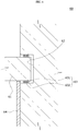
- FIG. 4 is a view schematically illustrating a state in which a prevention bearing and a prevention plate have been added to FIG. 3 .
- the bending prevention part 60 may further include a prevention bearing 63.
- the prevention bearing 63 is mounted at the prevention protrusion part 61 and is rotated by coming into contact with the prevention guide part 62.
- the prevention bearing 63 may include a bearing main body part 631 and a bearing ball part 632.
- the bearing main body part 631 may have a ring shape and surround the prevention protrusion part 61.
- the bearing main body part 631 may be disposed between the prevention protrusion part 61 and the prevention guide part 62.
- the bearing ball part 632 may be rotatably mounted at the bearing main body part 631 and protrude toward the outside of the bearing main body part 631.
- the bearing ball part 632 may come into contact with the prevention protrusion part 61 and the prevention guide part 62 and reduce frictional resistance in an operation process.
- the bending prevention part 60 may further include a prevention plate 64.
- the prevention plate 64 is mounted at the worm gear 30 and prevents deviation of the prevention bearing 63.
- the prevention plate 64 may have a disc shape and be assembled to a central portion of the worm gear groove part 312.
- An outer diameter of the prevention plate 64 may correspond to a distance from the central portion of the worm gear groove part 312 to the prevention bearing 63 so that an edge portion of the prevention plate 64 may prevent the prevention bearing 63 from being withdrawn from the prevention guide part 62.
- the driving gear 20 is mounted at the motor shaft 11 formed in the motor 10, and the driving gear 20 is inserted into the worm gear groove part 312 formed in the worm gear hub 31. In this case, the driving gear 20 is engaged with the hub gear part 311, and the prevention protrusion part 61 is inserted into the prevention guide part 62 formed in the worm gear groove part 312.
- prevention protrusion part 61 being inserted into the prevention guide part 62, bending of the motor shaft 11 may be prevented even when the state of excessive torque occurs between the driving gear 20 and the worm gear hub 31.
- an engaged state between the driving gear 20 and the worm gear hub 31 may be maintained, backlash may be prevented, and noise generation may be prevented.
- prevention bearing 63 being mounted at the prevention protrusion part 61, friction caused by direct contact between the prevention protrusion part 61 and the prevention guide part 62 may be prevented when the worm gear hub 31 is rotated due to driving of the motor 10.
- prevention plate 64 being mounted on the worm gear hub 31, deviation of the prevention bearing 63 may be prevented.
- the bending prevention part 60 suppresses an occurrence of bending of the motor 10 so that noise generation caused by backlash can be prevented.
- the prevention protrusion part 61 formed in the driving gear 20 is inserted into the prevention guide part 62 formed in the worm gear 30 so that an occurrence of bending can be suppressed.
- the prevention bearing 63 is mounted at the prevention protrusion part 61 so that friction caused by driving of the motor 10 can be reduced.
- the prevention plate 64 is mounted at the worm gear 30 so that deviation of the prevention bearing 63 can be prevented.
- motor 20 driving gear 30: worm gear 31: worm gear hub 32: worm gear shaft 40: movable mirror 50: stopper 60: bending prevention part 61: prevention protrusion part 62: prevention guide part 63: prevention bearing 64: prevention plate
Landscapes
- Engineering & Computer Science (AREA)
- Mechanical Engineering (AREA)
- Chemical & Material Sciences (AREA)
- Combustion & Propulsion (AREA)
- Transportation (AREA)
- Physics & Mathematics (AREA)
- General Physics & Mathematics (AREA)
- Optics & Photonics (AREA)
- General Engineering & Computer Science (AREA)
- Instrument Panels (AREA)
- Mounting And Adjusting Of Optical Elements (AREA)
- Mechanical Light Control Or Optical Switches (AREA)
Description
- The present invention relates to a driving device for a head-up display, and more particularly, to a driving device for a head-up display capable of preventing noise generation caused by friction or deviation among teeth caused by driving of a motor.
- Generally, a vehicle head-up display displays various pieces of vehicle information such as arrow information that is interlinked with a navigation system to guide a route change in a driver's field of view and text information indicating speed or the like in the form of augmented reality on a windshield or over the windshield, thereby preventing the scattering of the driver's line of sight.
- Since, to check the above-described pieces of vehicle information, there is no need for the driver to move his or her line of sight toward a terminal providing corresponding information, and the driver can travel while viewing a frontward area at which a head-up display image is output, the driver's safety is enhanced.
- The vehicle head-up display generates an image using a micro-display element, magnifies the generated image and forms the generated image into a virtual image through an optical projection system, and provides a vehicle information image to the driver.
- A conventional vehicle head-up display device reflects information projected from a display element through an aspherical mirror to display the information on a windshield and rotates a motor connected to the aspherical mirror to adjust an angle of reflection or a position of the aspherical mirror so that, as a result, a height of the display of the information displayed on the windshield is adjusted.
- A worm gear is used to move the aspherical mirror, and a motor and a spur gear are used for rotation of the worm gear. The spur gear may be engaged with an inside of a hub of the worm gear, and the aspherical mirror may be engaged with the worm gear and be moved horizontally.
- However, conventionally, when the aspherical mirror reaches a stopper due to rotation of the worm gear, there are problems in that an excessive torque load acts on an engaging portion between the worm gear and the spur gear, backlash occurs, and noise occurs due to friction or deviation among teeth. When the spur gear is rotated in the opposite direction in a state of excessive backlash, there is a problem in that, in a process in which teeth find their way back to their normal positions, noise occurs due to friction or deviation among the teeth. Therefore, there is a demand for improvement.
- The background art of the present invention is disclosed in
Korean Patent Publication No. 2016-0116139 - The present invention is directed to providing a driving device for a head-up display capable of preventing noise generation due to friction or deviation among teeth caused by driving of a motor.
- One aspect of the present invention provides a driving device for a head-up display including a motor, a driving gear mounted at the motor and rotated when the motor is driven, a worm gear engaged with the driving gear via an inside thereof and rotated by interlocking with the driving gear, a movable mirror configured to reflect an image signal and linearly moved by being engaged with the worm gear, a stopper configured to restrict movement of the movable mirror, and a bending prevention part connected to the driving gear and configured to be inserted into the worm gear. The worm gear includes a worm gear hub in which a hub gear part engaged with the driving gear is formed, and a worm gear shaft connected to the worm gear hub and configured to move the movable mirror by being engaged with the movable mirror.
- The bending prevention part includes a prevention protrusion part protruding from the driving gear, and a prevention guide part formed in the worm gear and into which the prevention protrusion part is inserted.
- The bending prevention part may further include a prevention bearing mounted at the prevention protrusion part and rotated by coming into contact with the prevention guide part.
- The bending prevention part may further include a prevention plate mounted at the worm gear and configured to prevent deviation of the prevention bearing.
- In a driving device for a head-up display according to the present invention, a bending prevention part suppresses an occurrence of the bending of a motor so that noise generation due to backlash can be prevented.
- In a driving device for a head-up display according to the present invention, a prevention protrusion part formed in a driving gear is inserted into a prevention guide part formed in a worm gear so that an occurrence of bending can be suppressed.
- In a driving device for a head-up display according to the present invention, a prevention bearing is mounted at a prevention protrusion part so that friction caused by driving of a motor can be reduced.
- In a driving device for a head-up display according to the present invention, a prevention plate is mounted at a worm gear so that deviation of a prevention bearing can be prevented.
-
-
FIG. 1 is a view schematically illustrating a driving device for a head-up display according to an embodiment of the present invention. -
FIG. 2 is a view schematically illustrating a worm gear in a driving device for a head-up display according to an embodiment of the present invention. -
FIG. 3 is a view schematically illustrating a bending prevention part in a driving device for a head-up display according to an embodiment of the present invention. -
FIG. 4 is a view schematically illustrating a state in which a prevention bearing and a prevention plate have been added toFIG. 3 . - Hereinafter, exemplary embodiments of a driving device for a head-up display according to the present invention will be described with reference to the accompanying drawings. In this process, thicknesses of lines, sizes of elements, or the like illustrated in the drawings may be exaggerated for clarity and convenience of description. The terms used below are terms defined in consideration of functions in the present invention, and thus may vary in accordance with an intention or practice of a user or an operator. Thus, such terms should be defined on the basis of content throughout the present specification.
-
FIG. 1 is a view schematically illustrating a driving device for a head-up display according to an embodiment of the present invention. Referring toFIG. 1 , a head-updisplay driving device 1 according to an embodiment of the present invention includes amotor 10, adriving gear 20, aworm gear 30, amovable mirror 40, astopper 50, and abending prevention part 60. - The
driving gear 20 is mounted at themotor 10, and when power is applied to themotor 10, thedriving gear 20 is rotated. For example, thedriving gear 20 may be connected to amotor shaft 11 of themotor 10 and have the shape of a spur gear. - The
worm gear 30 is rotated by being engaged with thedriving gear 20. For example, ring-shaped teeth arrangement may be formed inside theworm gear 30 and engaged with thedriving gear 20. Thus, theworm gear 30 may be interlocked with thedriving gear 20. - The
movable mirror 40 is linearly moved by being engaged with theworm gear 30, and reflects an image signal. For example, themovable mirror 40 has a lower portion engaged with theworm gear 30 and an upper portion configured to reflect an image signal so that a position of an image shown on a windshield may be adjusted. - The stopper 50 restricts movement of the
movable mirror 40. For example, thestopper 50 may be formed to include an elastic material and fixed to a vehicle body. Thestopper 50 may be disposed at each of both sides of a movement path of the linearly-movedmovable mirror 40 and restrict movement of themovable mirror 40. - The
bending prevention part 60 is connected to thedriving gear 20 and is inserted into theworm gear 30. Thebending prevention part 60 may prevent noise generation caused by bending of thedriving gear 20 in a state in which an excessive torque area is formed due to themovable mirror 40 reaching thestopper 50. -
FIG. 2 is a view schematically illustrating a worm gear in a driving device for a head-up display according to an embodiment of the present invention. Referring toFIGS. 1 and2 , theworm gear 30 according to an embodiment of the present invention includes aworm gear hub 31 and aworm gear shaft 32. - The
worm gear hub 31 has ahub gear part 311, which is engaged with thedriving gear 20, formed therein. For example, theworm gear hub 31 may have a disc shape, and a portion of one side surface of theworm gear hub 31 except for an edge thereof may be concave so that a wormgear groove part 312, which is a space into which thedriving gear 20 may be inserted, is formed in the concave portion. Also, thehub gear part 311 engaged with thedriving gear 20 may be formed in a circumferential direction in a wall surface corresponding to an edge of the wormgear groove part 312. Theworm gear shaft 32 is connected to theworm gear hub 31, and moves themovable mirror 40 by being engaged with themovable mirror 40. For example, theworm gear shaft 32 may extend from a central portion of the other side surface of theworm gear hub 31, and reciprocate themovable mirror 40 in accordance with a change in a rotating direction. -
FIG. 3 is a view schematically illustrating a bending prevention part in a driving device for a head-up display according to an embodiment of the present invention. Referring toFIGS. 1 to 3 , thebending prevention part 60 according to an embodiment of the present invention includes aprevention protrusion part 61 and aprevention guide part 62. - The
prevention protrusion part 61 protrudes from thedriving gear 20. For example, theprevention protrusion part 61 may protrude from a central portion of thedriving gear 20. Theprevention protrusion part 61 is assembled to thedriving gear 20 for replacement of theprevention protrusion part 61 when damage occurs. - The
prevention guide part 62 is formed in theworm gear 30, and forms a space into which theprevention protrusion part 61 is inserted. For example, theprevention guide part 62 may form a groove in the wormgear groove part 312 in the circumferential direction. -
FIG. 4 is a view schematically illustrating a state in which a prevention bearing and a prevention plate have been added toFIG. 3 . Referring toFIGS. 3 and4 , the bendingprevention part 60 according to an embodiment of the present invention may further include aprevention bearing 63. - The
prevention bearing 63 is mounted at theprevention protrusion part 61 and is rotated by coming into contact with theprevention guide part 62. For example, the prevention bearing 63 may include a bearingmain body part 631 and abearing ball part 632. The bearingmain body part 631 may have a ring shape and surround theprevention protrusion part 61. The bearingmain body part 631 may be disposed between theprevention protrusion part 61 and theprevention guide part 62. The bearingball part 632 may be rotatably mounted at the bearingmain body part 631 and protrude toward the outside of the bearingmain body part 631. The bearingball part 632 may come into contact with theprevention protrusion part 61 and theprevention guide part 62 and reduce frictional resistance in an operation process. - The bending
prevention part 60 according to an embodiment of the present invention may further include aprevention plate 64. Theprevention plate 64 is mounted at theworm gear 30 and prevents deviation of theprevention bearing 63. For example, theprevention plate 64 may have a disc shape and be assembled to a central portion of the wormgear groove part 312. An outer diameter of theprevention plate 64 may correspond to a distance from the central portion of the wormgear groove part 312 to the prevention bearing 63 so that an edge portion of theprevention plate 64 may prevent the prevention bearing 63 from being withdrawn from theprevention guide part 62. - The operation of the driving device for a head-up display according to an embodiment of the present invention having the above-described structure will be described below.
- The
driving gear 20 is mounted at themotor shaft 11 formed in themotor 10, and thedriving gear 20 is inserted into the wormgear groove part 312 formed in theworm gear hub 31. In this case, thedriving gear 20 is engaged with thehub gear part 311, and theprevention protrusion part 61 is inserted into theprevention guide part 62 formed in the wormgear groove part 312. - In the above-described state, when the
motor 10 is driven, thedriving gear 20 is rotated in one direction, and theworm gear hub 31 becomes interlocked therewith. Then, themovable mirror 40 engaged with theworm gear shaft 32 formed in theworm gear hub 31 is moved in one direction and reflects an image signal. - When the
movable mirror 40 reaches thestopper 50 due to driving of themotor 10, movement of themovable mirror 40 is restricted even when themotor 10 is driven. Thus, a state of excessive torque may occur between the drivinggear 20 and theworm gear hub 31 and cause themotor shaft 11 to be bent. - However, by the
prevention protrusion part 61 being inserted into theprevention guide part 62, bending of themotor shaft 11 may be prevented even when the state of excessive torque occurs between the drivinggear 20 and theworm gear hub 31. Thus, an engaged state between the drivinggear 20 and theworm gear hub 31 may be maintained, backlash may be prevented, and noise generation may be prevented. - In this case, by the prevention bearing 63 being mounted at the
prevention protrusion part 61, friction caused by direct contact between theprevention protrusion part 61 and theprevention guide part 62 may be prevented when theworm gear hub 31 is rotated due to driving of themotor 10. By theprevention plate 64 being mounted on theworm gear hub 31, deviation of the prevention bearing 63 may be prevented. - In the head-up
display driving device 1 according to an embodiment of the present invention, the bendingprevention part 60 suppresses an occurrence of bending of themotor 10 so that noise generation caused by backlash can be prevented. - In the head-up
display driving device 1 according to an embodiment of the present invention, theprevention protrusion part 61 formed in thedriving gear 20 is inserted into theprevention guide part 62 formed in theworm gear 30 so that an occurrence of bending can be suppressed. - In the head-up
display driving device 1 according to an embodiment of the present invention, the prevention bearing 63 is mounted at theprevention protrusion part 61 so that friction caused by driving of themotor 10 can be reduced. - In the head-up
display driving device 1 according to an embodiment of the present invention, theprevention plate 64 is mounted at theworm gear 30 so that deviation of the prevention bearing 63 can be prevented. - Although the present invention has been described with reference to the embodiments illustrated in the drawings, the embodiments are merely illustrative, and one of ordinary skill in the art to which the present invention pertains should understand that various modifications and other equivalent embodiments are possible from the above-described embodiments. Therefore, the actual technical scope of the present invention should be defined by the claims below.
-
10: motor 20: driving gear 30: worm gear 31: worm gear hub 32: worm gear shaft 40: movable mirror 50: stopper 60: bending prevention part 61: prevention protrusion part 62: prevention guide part 63: prevention bearing 64: prevention plate
Claims (3)
- A driving device for a head-up display, the driving device (1) comprising:a motor (10);a driving gear (20) mounted at the motor (10) and rotated when the motor (10) is driven;a worm gear (30) engaged with the driving gear (20) via an inside thereof and rotated by interlocking with the driving gear (20);a movable mirror (40) configured to reflect an image signal and linearly moved by being engaged with the worm gear (30);a stopper (50) configured to restrict movement of the movable mirror (40); anda bending prevention part (60) connected to the driving gear (20) and configured to be inserted into the worm gear (30), wherein the worm gear (30) includes:a worm gear hub (31) in which a hub gear part engaged with the driving gear (20) is formed; anda worm gear shaft (32) connected to the worm gear hub (31) and configured to move the movable mirror (40) by being engaged with the movable mirror (40), and wherein the bending prevention part (60) includes:a prevention protrusion part (61)n protruding from the driving gear (20); anda prevention guide part (62) formed in the worm gear (30) and into which the prevention protrusion part (61) is inserted.
- The driving device of claim 1, wherein the bending prevention part (60) further includes a prevention bearing (62) mounted at the prevention protrusion part (61) and rotated by coming into contact with the prevention guide part (62).
- The driving device of claim 2, wherein the bending prevention part (60) further includes a prevention plate (64) mounted at the worm gear (30) and configured to prevent deviation of the prevention bearing (63) from the prevention guide part (62).
Applications Claiming Priority (2)
| Application Number | Priority Date | Filing Date | Title |
|---|---|---|---|
| KR1020170069119A KR101912648B1 (en) | 2017-06-02 | 2017-06-02 | Operating device foe head up display |
| PCT/EP2018/062936 WO2018219672A1 (en) | 2017-06-02 | 2018-05-17 | Driving device for head-up display |
Publications (2)
| Publication Number | Publication Date |
|---|---|
| EP3631550A1 EP3631550A1 (en) | 2020-04-08 |
| EP3631550B1 true EP3631550B1 (en) | 2021-07-28 |
Family
ID=62528404
Family Applications (1)
| Application Number | Title | Priority Date | Filing Date |
|---|---|---|---|
| EP18729049.9A Active EP3631550B1 (en) | 2017-06-02 | 2018-05-17 | Driving device for head-up display |
Country Status (6)
| Country | Link |
|---|---|
| US (1) | US11125995B2 (en) |
| EP (1) | EP3631550B1 (en) |
| JP (1) | JP6877591B2 (en) |
| KR (1) | KR101912648B1 (en) |
| CN (1) | CN110622052B (en) |
| WO (1) | WO2018219672A1 (en) |
Families Citing this family (1)
| Publication number | Priority date | Publication date | Assignee | Title |
|---|---|---|---|---|
| KR102648818B1 (en) * | 2019-01-29 | 2024-03-19 | 현대자동차주식회사 | Infortainment apparatus for vehicle and method for controlling the same and vehicle including the same |
Citations (1)
| Publication number | Priority date | Publication date | Assignee | Title |
|---|---|---|---|---|
| JP2010203550A (en) * | 2009-03-04 | 2010-09-16 | Kenwood Corp | Gear idling mechanism and disc player |
Family Cites Families (43)
| Publication number | Priority date | Publication date | Assignee | Title |
|---|---|---|---|---|
| US5905477A (en) * | 1996-08-12 | 1999-05-18 | Shimadzu Corporation | Head-up display having installation mechanism |
| JP3891646B2 (en) * | 1997-07-18 | 2007-03-14 | 株式会社ショーワ | Gear mounting structure of torque limiter interposition part in electric power steering device |
| DE102006014394A1 (en) | 2006-03-29 | 2007-10-11 | GM Global Technology Operations, Inc., Detroit | Head-up display, motor vehicle and method for operating a head-up display |
| JP4675824B2 (en) * | 2006-05-15 | 2011-04-27 | カルソニックカンセイ株式会社 | Vehicle display device |
| JP2009150947A (en) | 2007-12-19 | 2009-07-09 | Hitachi Ltd | Head-up display device for vehicle |
| JP5348459B2 (en) | 2008-05-26 | 2013-11-20 | 日本精機株式会社 | Power transmission device used for vehicle head-up display device |
| JP5446837B2 (en) | 2009-12-22 | 2014-03-19 | 株式会社デンソー | Head-up display device |
| JP5240222B2 (en) * | 2010-03-26 | 2013-07-17 | 株式会社デンソー | Head-up display device |
| JP2012053326A (en) | 2010-09-02 | 2012-03-15 | Seiko Epson Corp | Optical element |
| JP5883873B2 (en) | 2010-09-18 | 2016-03-15 | ジョンソン・コントロールズ・ゲー・エム・ベー・ハー | Display unit consisting of projection screen for head-up display |
| DE102011014145A1 (en) | 2010-12-23 | 2012-06-28 | Continental Automotive Gmbh | Head-up display for a motor vehicle |
| US8953247B2 (en) * | 2011-01-20 | 2015-02-10 | Lite-On Technology Corporation | Positioning system for head-up display |
| WO2013041212A2 (en) | 2011-09-19 | 2013-03-28 | Kappel, Andreas | Rotary actuator |
| JP5890164B2 (en) | 2011-12-15 | 2016-03-22 | 矢崎総業株式会社 | Head-up display device |
| JP6002901B2 (en) | 2012-10-04 | 2016-10-05 | 株式会社 神崎高級工機製作所 | Hydraulic continuously variable transmission |
| JP6130641B2 (en) | 2012-10-04 | 2017-05-17 | プレサイスゲージ株式会社 | Rotating mechanism |
| KR101396450B1 (en) | 2013-01-07 | 2014-05-20 | 주식회사 대동 | Display module for vehicle |
| JP6116932B2 (en) * | 2013-02-21 | 2017-04-19 | 矢崎総業株式会社 | Vehicle display device |
| US9164281B2 (en) | 2013-03-15 | 2015-10-20 | Honda Motor Co., Ltd. | Volumetric heads-up display with dynamic focal plane |
| JP6044838B2 (en) | 2013-04-04 | 2016-12-14 | 日本精機株式会社 | Head-up display device |
| DE102013215816B3 (en) * | 2013-04-22 | 2014-10-16 | Magna Powertrain Ag & Co. Kg | Phaser |
| CN103345042A (en) | 2013-07-29 | 2013-10-09 | 江苏睿维申电子科技有限公司 | Reflector adjusting system for head-up display |
| KR101558658B1 (en) | 2013-09-06 | 2015-10-07 | 현대자동차주식회사 | Head up display device for vehicle |
| EP2857239A1 (en) * | 2013-10-03 | 2015-04-08 | Volvo Car Corporation | Digital sunshade for automotive glass |
| US9368867B2 (en) | 2013-10-07 | 2016-06-14 | Harris Corporation | Near-linear drive systems for positioning reflectors |
| CN203811900U (en) | 2013-12-13 | 2014-09-03 | 惠州市华阳多媒体电子有限公司 | Head up display and vehicle |
| JP6326936B2 (en) | 2014-04-23 | 2018-05-23 | 日本精機株式会社 | Display device |
| JP6267583B2 (en) | 2014-05-16 | 2018-01-24 | ミネベアミツミ株式会社 | Tilt mechanism and display device having the same |
| DE102014211485A1 (en) | 2014-06-16 | 2015-12-17 | Continental Automotive Gmbh | Positioning device for a Combinerscheibe a head-up display of a vehicle |
| JP2016008674A (en) | 2014-06-25 | 2016-01-18 | 日本精機株式会社 | Drive unit |
| JP6435159B2 (en) * | 2014-10-17 | 2018-12-05 | ミネベアミツミ株式会社 | Angle adjustment mechanism and display device |
| DE102014118380A1 (en) | 2014-12-11 | 2016-06-16 | Valeo Schalter Und Sensoren Gmbh | Display device for a motor vehicle with force sensor, motor vehicle and method |
| CN204439935U (en) | 2014-12-25 | 2015-07-01 | 高智投资有限公司 | Automobile and head-up display device thereof |
| KR102321095B1 (en) | 2015-03-26 | 2021-11-04 | 현대모비스 주식회사 | Head up display device of a vehicle and the control method thereof |
| CN105022168B (en) | 2015-07-15 | 2018-08-03 | 惠州市华阳多媒体电子有限公司 | A kind of HUD picture altitudes regulating device |
| DE102015111618B4 (en) | 2015-07-17 | 2020-11-26 | Valeo Schalter Und Sensoren Gmbh | Display device for a motor vehicle with overload protection and a motor vehicle |
| CN105083148B (en) * | 2015-08-04 | 2018-08-03 | 惠州市华阳多媒体电子有限公司 | A kind of turnover device of head up display |
| JP2017068190A (en) * | 2015-10-02 | 2017-04-06 | 日本精機株式会社 | Headup display |
| KR101640579B1 (en) | 2015-11-06 | 2016-07-19 | 콘티넨탈 오토모티브 일렉트로닉스 유한회사 | Head-up display |
| CN106154558A (en) | 2016-08-31 | 2016-11-23 | 上海伟世通汽车电子系统有限公司 | The reflective viewing screen draw off gear of HUD |
| US20190107717A1 (en) * | 2017-10-05 | 2019-04-11 | Visteon Global Technologies, Inc. | Head-up display system |
| WO2019102731A1 (en) * | 2017-11-24 | 2019-05-31 | マクセル株式会社 | Head-up display device |
| US10684473B2 (en) * | 2017-12-22 | 2020-06-16 | Lite-On Electronics (Guangzhou) Limited | Angle-adjusting mechanism of head-up display |
-
2017
- 2017-06-02 KR KR1020170069119A patent/KR101912648B1/en active Active
-
2018
- 2018-05-17 US US16/617,353 patent/US11125995B2/en active Active
- 2018-05-17 CN CN201880029750.8A patent/CN110622052B/en active Active
- 2018-05-17 WO PCT/EP2018/062936 patent/WO2018219672A1/en not_active Ceased
- 2018-05-17 EP EP18729049.9A patent/EP3631550B1/en active Active
- 2018-05-17 JP JP2019565472A patent/JP6877591B2/en active Active
Patent Citations (1)
| Publication number | Priority date | Publication date | Assignee | Title |
|---|---|---|---|---|
| JP2010203550A (en) * | 2009-03-04 | 2010-09-16 | Kenwood Corp | Gear idling mechanism and disc player |
Also Published As
| Publication number | Publication date |
|---|---|
| WO2018219672A1 (en) | 2018-12-06 |
| JP2020522015A (en) | 2020-07-27 |
| EP3631550A1 (en) | 2020-04-08 |
| US11125995B2 (en) | 2021-09-21 |
| KR101912648B1 (en) | 2018-10-29 |
| CN110622052A (en) | 2019-12-27 |
| US20210132381A1 (en) | 2021-05-06 |
| CN110622052B (en) | 2021-11-16 |
| JP6877591B2 (en) | 2021-05-26 |
Similar Documents
| Publication | Publication Date | Title |
|---|---|---|
| US11281004B2 (en) | Rotating device for rotating rotation object and head-up display device | |
| EP3128357B1 (en) | Display device | |
| KR102253005B1 (en) | Driving Module for Head-UP Display Device | |
| US7659868B2 (en) | Head-up display apparatus and cover-mirror unit used for the same | |
| US8102601B2 (en) | Head up display device for vehicle | |
| JP6435159B2 (en) | Angle adjustment mechanism and display device | |
| US20170307885A1 (en) | Head-up display for a motor vehicle | |
| WO2017077035A1 (en) | Head up display | |
| EP3631550B1 (en) | Driving device for head-up display | |
| JP2006062501A (en) | Head-up display | |
| US10684473B2 (en) | Angle-adjusting mechanism of head-up display | |
| WO2020161954A1 (en) | Display device and method for installing display device | |
| JP6808291B2 (en) | Head-up display device | |
| US20170276939A1 (en) | Display, in particular for a motor vehicle | |
| US12181669B2 (en) | Head-up display apparatus in which reflecting mirror is rotated | |
| KR102038999B1 (en) | Head up display | |
| JP2017203881A (en) | Display position adjustment unit and head-up display device | |
| EP3307590B1 (en) | Kinematic mechanism for a head-up display | |
| JP2006065091A (en) | Head-up display | |
| US8963697B2 (en) | Display device, in particular for a motor vehicle | |
| EP3696596A1 (en) | Vehicle display device | |
| US20210193086A1 (en) | Head up display configuration | |
| EP4516557A1 (en) | Display device for vehicle | |
| JP7623330B2 (en) | Vehicle display device | |
| KR101960416B1 (en) | Head up display |
Legal Events
| Date | Code | Title | Description |
|---|---|---|---|
| STAA | Information on the status of an ep patent application or granted ep patent |
Free format text: STATUS: UNKNOWN |
|
| STAA | Information on the status of an ep patent application or granted ep patent |
Free format text: STATUS: THE INTERNATIONAL PUBLICATION HAS BEEN MADE |
|
| PUAI | Public reference made under article 153(3) epc to a published international application that has entered the european phase |
Free format text: ORIGINAL CODE: 0009012 |
|
| STAA | Information on the status of an ep patent application or granted ep patent |
Free format text: STATUS: REQUEST FOR EXAMINATION WAS MADE |
|
| 17P | Request for examination filed |
Effective date: 20200102 |
|
| AK | Designated contracting states |
Kind code of ref document: A1 Designated state(s): AL AT BE BG CH CY CZ DE DK EE ES FI FR GB GR HR HU IE IS IT LI LT LU LV MC MK MT NL NO PL PT RO RS SE SI SK SM TR |
|
| AX | Request for extension of the european patent |
Extension state: BA ME |
|
| DAV | Request for validation of the european patent (deleted) | ||
| DAX | Request for extension of the european patent (deleted) | ||
| STAA | Information on the status of an ep patent application or granted ep patent |
Free format text: STATUS: EXAMINATION IS IN PROGRESS |
|
| 17Q | First examination report despatched |
Effective date: 20201120 |
|
| GRAP | Despatch of communication of intention to grant a patent |
Free format text: ORIGINAL CODE: EPIDOSNIGR1 |
|
| STAA | Information on the status of an ep patent application or granted ep patent |
Free format text: STATUS: GRANT OF PATENT IS INTENDED |
|
| INTG | Intention to grant announced |
Effective date: 20210330 |
|
| GRAS | Grant fee paid |
Free format text: ORIGINAL CODE: EPIDOSNIGR3 |
|
| GRAA | (expected) grant |
Free format text: ORIGINAL CODE: 0009210 |
|
| STAA | Information on the status of an ep patent application or granted ep patent |
Free format text: STATUS: THE PATENT HAS BEEN GRANTED |
|
| AK | Designated contracting states |
Kind code of ref document: B1 Designated state(s): AL AT BE BG CH CY CZ DE DK EE ES FI FR GB GR HR HU IE IS IT LI LT LU LV MC MK MT NL NO PL PT RO RS SE SI SK SM TR |
|
| REG | Reference to a national code |
Ref country code: GB Ref legal event code: FG4D |
|
| REG | Reference to a national code |
Ref country code: CH Ref legal event code: EP |
|
| REG | Reference to a national code |
Ref country code: AT Ref legal event code: REF Ref document number: 1415213 Country of ref document: AT Kind code of ref document: T Effective date: 20210815 |
|
| REG | Reference to a national code |
Ref country code: IE Ref legal event code: FG4D |
|
| REG | Reference to a national code |
Ref country code: DE Ref legal event code: R096 Ref document number: 602018020814 Country of ref document: DE |
|
| REG | Reference to a national code |
Ref country code: LT Ref legal event code: MG9D |
|
| REG | Reference to a national code |
Ref country code: NL Ref legal event code: MP Effective date: 20210728 |
|
| REG | Reference to a national code |
Ref country code: AT Ref legal event code: MK05 Ref document number: 1415213 Country of ref document: AT Kind code of ref document: T Effective date: 20210728 |
|
| PG25 | Lapsed in a contracting state [announced via postgrant information from national office to epo] |
Ref country code: SE Free format text: LAPSE BECAUSE OF FAILURE TO SUBMIT A TRANSLATION OF THE DESCRIPTION OR TO PAY THE FEE WITHIN THE PRESCRIBED TIME-LIMIT Effective date: 20210728 Ref country code: RS Free format text: LAPSE BECAUSE OF FAILURE TO SUBMIT A TRANSLATION OF THE DESCRIPTION OR TO PAY THE FEE WITHIN THE PRESCRIBED TIME-LIMIT Effective date: 20210728 Ref country code: HR Free format text: LAPSE BECAUSE OF FAILURE TO SUBMIT A TRANSLATION OF THE DESCRIPTION OR TO PAY THE FEE WITHIN THE PRESCRIBED TIME-LIMIT Effective date: 20210728 Ref country code: ES Free format text: LAPSE BECAUSE OF FAILURE TO SUBMIT A TRANSLATION OF THE DESCRIPTION OR TO PAY THE FEE WITHIN THE PRESCRIBED TIME-LIMIT Effective date: 20210728 Ref country code: FI Free format text: LAPSE BECAUSE OF FAILURE TO SUBMIT A TRANSLATION OF THE DESCRIPTION OR TO PAY THE FEE WITHIN THE PRESCRIBED TIME-LIMIT Effective date: 20210728 Ref country code: AT Free format text: LAPSE BECAUSE OF FAILURE TO SUBMIT A TRANSLATION OF THE DESCRIPTION OR TO PAY THE FEE WITHIN THE PRESCRIBED TIME-LIMIT Effective date: 20210728 Ref country code: BG Free format text: LAPSE BECAUSE OF FAILURE TO SUBMIT A TRANSLATION OF THE DESCRIPTION OR TO PAY THE FEE WITHIN THE PRESCRIBED TIME-LIMIT Effective date: 20211028 Ref country code: LT Free format text: LAPSE BECAUSE OF FAILURE TO SUBMIT A TRANSLATION OF THE DESCRIPTION OR TO PAY THE FEE WITHIN THE PRESCRIBED TIME-LIMIT Effective date: 20210728 Ref country code: PT Free format text: LAPSE BECAUSE OF FAILURE TO SUBMIT A TRANSLATION OF THE DESCRIPTION OR TO PAY THE FEE WITHIN THE PRESCRIBED TIME-LIMIT Effective date: 20211129 Ref country code: NL Free format text: LAPSE BECAUSE OF FAILURE TO SUBMIT A TRANSLATION OF THE DESCRIPTION OR TO PAY THE FEE WITHIN THE PRESCRIBED TIME-LIMIT Effective date: 20210728 Ref country code: NO Free format text: LAPSE BECAUSE OF FAILURE TO SUBMIT A TRANSLATION OF THE DESCRIPTION OR TO PAY THE FEE WITHIN THE PRESCRIBED TIME-LIMIT Effective date: 20211028 |
|
| PG25 | Lapsed in a contracting state [announced via postgrant information from national office to epo] |
Ref country code: PL Free format text: LAPSE BECAUSE OF FAILURE TO SUBMIT A TRANSLATION OF THE DESCRIPTION OR TO PAY THE FEE WITHIN THE PRESCRIBED TIME-LIMIT Effective date: 20210728 Ref country code: LV Free format text: LAPSE BECAUSE OF FAILURE TO SUBMIT A TRANSLATION OF THE DESCRIPTION OR TO PAY THE FEE WITHIN THE PRESCRIBED TIME-LIMIT Effective date: 20210728 Ref country code: GR Free format text: LAPSE BECAUSE OF FAILURE TO SUBMIT A TRANSLATION OF THE DESCRIPTION OR TO PAY THE FEE WITHIN THE PRESCRIBED TIME-LIMIT Effective date: 20211029 |
|
| PG25 | Lapsed in a contracting state [announced via postgrant information from national office to epo] |
Ref country code: DK Free format text: LAPSE BECAUSE OF FAILURE TO SUBMIT A TRANSLATION OF THE DESCRIPTION OR TO PAY THE FEE WITHIN THE PRESCRIBED TIME-LIMIT Effective date: 20210728 |
|
| REG | Reference to a national code |
Ref country code: DE Ref legal event code: R097 Ref document number: 602018020814 Country of ref document: DE |
|
| PG25 | Lapsed in a contracting state [announced via postgrant information from national office to epo] |
Ref country code: SM Free format text: LAPSE BECAUSE OF FAILURE TO SUBMIT A TRANSLATION OF THE DESCRIPTION OR TO PAY THE FEE WITHIN THE PRESCRIBED TIME-LIMIT Effective date: 20210728 Ref country code: SK Free format text: LAPSE BECAUSE OF FAILURE TO SUBMIT A TRANSLATION OF THE DESCRIPTION OR TO PAY THE FEE WITHIN THE PRESCRIBED TIME-LIMIT Effective date: 20210728 Ref country code: RO Free format text: LAPSE BECAUSE OF FAILURE TO SUBMIT A TRANSLATION OF THE DESCRIPTION OR TO PAY THE FEE WITHIN THE PRESCRIBED TIME-LIMIT Effective date: 20210728 Ref country code: EE Free format text: LAPSE BECAUSE OF FAILURE TO SUBMIT A TRANSLATION OF THE DESCRIPTION OR TO PAY THE FEE WITHIN THE PRESCRIBED TIME-LIMIT Effective date: 20210728 Ref country code: CZ Free format text: LAPSE BECAUSE OF FAILURE TO SUBMIT A TRANSLATION OF THE DESCRIPTION OR TO PAY THE FEE WITHIN THE PRESCRIBED TIME-LIMIT Effective date: 20210728 Ref country code: AL Free format text: LAPSE BECAUSE OF FAILURE TO SUBMIT A TRANSLATION OF THE DESCRIPTION OR TO PAY THE FEE WITHIN THE PRESCRIBED TIME-LIMIT Effective date: 20210728 |
|
| PLBE | No opposition filed within time limit |
Free format text: ORIGINAL CODE: 0009261 |
|
| STAA | Information on the status of an ep patent application or granted ep patent |
Free format text: STATUS: NO OPPOSITION FILED WITHIN TIME LIMIT |
|
| 26N | No opposition filed |
Effective date: 20220429 |
|
| REG | Reference to a national code |
Ref country code: DE Ref legal event code: R081 Ref document number: 602018020814 Country of ref document: DE Owner name: CONTINENTAL AUTOMOTIVE TECHNOLOGIES GMBH, DE Free format text: FORMER OWNER: CONTINENTAL AUTOMOTIVE GMBH, 30165 HANNOVER, DE Ref country code: DE Ref legal event code: R081 Ref document number: 602018020814 Country of ref document: DE Owner name: AUMOVIO GERMANY GMBH, DE Free format text: FORMER OWNER: CONTINENTAL AUTOMOTIVE GMBH, 30165 HANNOVER, DE |
|
| PG25 | Lapsed in a contracting state [announced via postgrant information from national office to epo] |
Ref country code: IT Free format text: LAPSE BECAUSE OF FAILURE TO SUBMIT A TRANSLATION OF THE DESCRIPTION OR TO PAY THE FEE WITHIN THE PRESCRIBED TIME-LIMIT Effective date: 20210728 |
|
| REG | Reference to a national code |
Ref country code: CH Ref legal event code: PL |
|
| REG | Reference to a national code |
Ref country code: BE Ref legal event code: MM Effective date: 20220531 |
|
| PG25 | Lapsed in a contracting state [announced via postgrant information from national office to epo] |
Ref country code: MC Free format text: LAPSE BECAUSE OF FAILURE TO SUBMIT A TRANSLATION OF THE DESCRIPTION OR TO PAY THE FEE WITHIN THE PRESCRIBED TIME-LIMIT Effective date: 20210728 Ref country code: LU Free format text: LAPSE BECAUSE OF NON-PAYMENT OF DUE FEES Effective date: 20220517 Ref country code: LI Free format text: LAPSE BECAUSE OF NON-PAYMENT OF DUE FEES Effective date: 20220531 Ref country code: CH Free format text: LAPSE BECAUSE OF NON-PAYMENT OF DUE FEES Effective date: 20220531 |
|
| REG | Reference to a national code |
Ref country code: GB Ref legal event code: 732E Free format text: REGISTERED BETWEEN 20230223 AND 20230301 |
|
| PG25 | Lapsed in a contracting state [announced via postgrant information from national office to epo] |
Ref country code: IE Free format text: LAPSE BECAUSE OF NON-PAYMENT OF DUE FEES Effective date: 20220517 |
|
| PG25 | Lapsed in a contracting state [announced via postgrant information from national office to epo] |
Ref country code: BE Free format text: LAPSE BECAUSE OF NON-PAYMENT OF DUE FEES Effective date: 20220531 |
|
| P01 | Opt-out of the competence of the unified patent court (upc) registered |
Effective date: 20230522 |
|
| REG | Reference to a national code |
Ref country code: DE Ref legal event code: R081 Ref document number: 602018020814 Country of ref document: DE Owner name: CONTINENTAL AUTOMOTIVE TECHNOLOGIES GMBH, DE Free format text: FORMER OWNER: CONTINENTAL AUTOMOTIVE TECHNOLOGIES GMBH, 30165 HANNOVER, DE Ref country code: DE Ref legal event code: R081 Ref document number: 602018020814 Country of ref document: DE Owner name: AUMOVIO GERMANY GMBH, DE Free format text: FORMER OWNER: CONTINENTAL AUTOMOTIVE TECHNOLOGIES GMBH, 30165 HANNOVER, DE |
|
| PG25 | Lapsed in a contracting state [announced via postgrant information from national office to epo] |
Ref country code: MK Free format text: LAPSE BECAUSE OF FAILURE TO SUBMIT A TRANSLATION OF THE DESCRIPTION OR TO PAY THE FEE WITHIN THE PRESCRIBED TIME-LIMIT Effective date: 20210728 Ref country code: CY Free format text: LAPSE BECAUSE OF FAILURE TO SUBMIT A TRANSLATION OF THE DESCRIPTION OR TO PAY THE FEE WITHIN THE PRESCRIBED TIME-LIMIT Effective date: 20210728 |
|
| PG25 | Lapsed in a contracting state [announced via postgrant information from national office to epo] |
Ref country code: HU Free format text: LAPSE BECAUSE OF FAILURE TO SUBMIT A TRANSLATION OF THE DESCRIPTION OR TO PAY THE FEE WITHIN THE PRESCRIBED TIME-LIMIT; INVALID AB INITIO Effective date: 20180517 |
|
| PG25 | Lapsed in a contracting state [announced via postgrant information from national office to epo] |
Ref country code: TR Free format text: LAPSE BECAUSE OF FAILURE TO SUBMIT A TRANSLATION OF THE DESCRIPTION OR TO PAY THE FEE WITHIN THE PRESCRIBED TIME-LIMIT Effective date: 20210728 |
|
| PG25 | Lapsed in a contracting state [announced via postgrant information from national office to epo] |
Ref country code: MT Free format text: LAPSE BECAUSE OF FAILURE TO SUBMIT A TRANSLATION OF THE DESCRIPTION OR TO PAY THE FEE WITHIN THE PRESCRIBED TIME-LIMIT Effective date: 20210728 |
|
| PGFP | Annual fee paid to national office [announced via postgrant information from national office to epo] |
Ref country code: DE Payment date: 20250531 Year of fee payment: 8 |
|
| PGFP | Annual fee paid to national office [announced via postgrant information from national office to epo] |
Ref country code: FR Payment date: 20250528 Year of fee payment: 8 |
|
| REG | Reference to a national code |
Ref country code: DE Ref legal event code: R081 Ref document number: 602018020814 Country of ref document: DE Owner name: AUMOVIO GERMANY GMBH, DE Free format text: FORMER OWNER: CONTINENTAL AUTOMOTIVE TECHNOLOGIES GMBH, 30175 HANNOVER, DE |
|
| PGFP | Annual fee paid to national office [announced via postgrant information from national office to epo] |
Ref country code: GB Payment date: 20260313 Year of fee payment: 9 |