EP3631435B1 - Eddy current sensor comprising triangular coils for non-destructive testing of a substrate - Google Patents
Eddy current sensor comprising triangular coils for non-destructive testing of a substrate Download PDFInfo
- Publication number
- EP3631435B1 EP3631435B1 EP18729054.9A EP18729054A EP3631435B1 EP 3631435 B1 EP3631435 B1 EP 3631435B1 EP 18729054 A EP18729054 A EP 18729054A EP 3631435 B1 EP3631435 B1 EP 3631435B1
- Authority
- EP
- European Patent Office
- Prior art keywords
- eddy current
- current sensor
- coil
- coils
- sub
- Prior art date
- Legal status (The legal status is an assumption and is not a legal conclusion. Google has not performed a legal analysis and makes no representation as to the accuracy of the status listed.)
- Active
Links
Images




Classifications
-
- G—PHYSICS
- G01—MEASURING; TESTING
- G01N—INVESTIGATING OR ANALYSING MATERIALS BY DETERMINING THEIR CHEMICAL OR PHYSICAL PROPERTIES
- G01N27/00—Investigating or analysing materials by the use of electric, electrochemical, or magnetic means
- G01N27/72—Investigating or analysing materials by the use of electric, electrochemical, or magnetic means by investigating magnetic variables
- G01N27/82—Investigating or analysing materials by the use of electric, electrochemical, or magnetic means by investigating magnetic variables for investigating the presence of flaws
- G01N27/90—Investigating or analysing materials by the use of electric, electrochemical, or magnetic means by investigating magnetic variables for investigating the presence of flaws using eddy currents
- G01N27/9006—Details, e.g. in the structure or functioning of sensors
-
- G—PHYSICS
- G01—MEASURING; TESTING
- G01D—MEASURING NOT SPECIALLY ADAPTED FOR A SPECIFIC VARIABLE; ARRANGEMENTS FOR MEASURING TWO OR MORE VARIABLES NOT COVERED IN A SINGLE OTHER SUBCLASS; TARIFF METERING APPARATUS; MEASURING OR TESTING NOT OTHERWISE PROVIDED FOR
- G01D5/00—Mechanical means for transferring the output of a sensing member; Means for converting the output of a sensing member to another variable where the form or nature of the sensing member does not constrain the means for converting; Transducers not specially adapted for a specific variable
- G01D5/12—Mechanical means for transferring the output of a sensing member; Means for converting the output of a sensing member to another variable where the form or nature of the sensing member does not constrain the means for converting; Transducers not specially adapted for a specific variable using electric or magnetic means
- G01D5/14—Mechanical means for transferring the output of a sensing member; Means for converting the output of a sensing member to another variable where the form or nature of the sensing member does not constrain the means for converting; Transducers not specially adapted for a specific variable using electric or magnetic means influencing the magnitude of a current or voltage
- G01D5/20—Mechanical means for transferring the output of a sensing member; Means for converting the output of a sensing member to another variable where the form or nature of the sensing member does not constrain the means for converting; Transducers not specially adapted for a specific variable using electric or magnetic means influencing the magnitude of a current or voltage by varying inductance, e.g. by a movable armature
- G01D5/204—Mechanical means for transferring the output of a sensing member; Means for converting the output of a sensing member to another variable where the form or nature of the sensing member does not constrain the means for converting; Transducers not specially adapted for a specific variable using electric or magnetic means influencing the magnitude of a current or voltage by varying inductance, e.g. by a movable armature by influencing the mutual induction between two or more coils
- G01D5/2053—Mechanical means for transferring the output of a sensing member; Means for converting the output of a sensing member to another variable where the form or nature of the sensing member does not constrain the means for converting; Transducers not specially adapted for a specific variable using electric or magnetic means influencing the magnitude of a current or voltage by varying inductance, e.g. by a movable armature by influencing the mutual induction between two or more coils by a movable non-ferromagnetic conductive element
-
- G—PHYSICS
- G01—MEASURING; TESTING
- G01N—INVESTIGATING OR ANALYSING MATERIALS BY DETERMINING THEIR CHEMICAL OR PHYSICAL PROPERTIES
- G01N27/00—Investigating or analysing materials by the use of electric, electrochemical, or magnetic means
- G01N27/72—Investigating or analysing materials by the use of electric, electrochemical, or magnetic means by investigating magnetic variables
- G01N27/82—Investigating or analysing materials by the use of electric, electrochemical, or magnetic means by investigating magnetic variables for investigating the presence of flaws
- G01N27/90—Investigating or analysing materials by the use of electric, electrochemical, or magnetic means by investigating magnetic variables for investigating the presence of flaws using eddy currents
- G01N27/9013—Arrangements for scanning
- G01N27/902—Arrangements for scanning by moving the sensors
-
- G—PHYSICS
- G01—MEASURING; TESTING
- G01N—INVESTIGATING OR ANALYSING MATERIALS BY DETERMINING THEIR CHEMICAL OR PHYSICAL PROPERTIES
- G01N27/00—Investigating or analysing materials by the use of electric, electrochemical, or magnetic means
- G01N27/72—Investigating or analysing materials by the use of electric, electrochemical, or magnetic means by investigating magnetic variables
- G01N27/82—Investigating or analysing materials by the use of electric, electrochemical, or magnetic means by investigating magnetic variables for investigating the presence of flaws
- G01N27/90—Investigating or analysing materials by the use of electric, electrochemical, or magnetic means by investigating magnetic variables for investigating the presence of flaws using eddy currents
- G01N27/9046—Investigating or analysing materials by the use of electric, electrochemical, or magnetic means by investigating magnetic variables for investigating the presence of flaws using eddy currents by analysing electrical signals
Definitions
- the invention relates to an eddy current sensor for the non-destructive testing of a substrate as defined in claim 1, in particular for the testing of a layered substrate made up of plies reinforced by fibers having a preferential direction. Furthermore, the invention relates to a method of operating an eddy current sensor wherein the eddy current sensor comprises a plurality of eddy current sensor elements as defined in claim 10. Moreover, the invention relates to a use of an eddy current sensor for a non-destructive testing of a substrate as defined in claim 12.
- an eddy current sensor comprises a flat coil which is arranged in close proximity to the surface of the material to be tested.
- a signal e. g. an alternating voltage
- the sensor coil is excited and an alternating electromagnetic field is generated which penetrates into the material to be probed.
- the alternating electromagnetic field induces in the material eddy currents which themselves are sensed by the coil as a change in the impedance.
- the surface area which is tested is given by the contour of the coil to which the signal is applied.
- an eddy current sensor is particularly known for the testing of layered materials, such as laminates, in particular for the testing of plies made up of carbon fiber reinforced polymer (CFRP) layers.
- CFRP carbon fiber reinforced polymer
- an eddy current sensor which has usually a rectangular shape, is used to study the number as well as the orientation of plies. The relative orientation of the plies is deduced from the orientation of the carbon fibers which reinforce each ply.
- JP S60 141549 U discloses an eddy current sensor, wherein the coils are formed as equilateral triangles and wherein the triangular coils do not have a 90° angle. JP S60 141549 U discloses that two coils are rotated to make a differential coupling so that a relative movement of the coils is required in order to measure a response.
- US 2003/151402 A1 discloses a device for contactless measurement of a displacement path, especially for the detection of position and movement.
- the flat coils used have a triangular shape so that two opposed triangular coils form a rectangular shape.
- a target In order to measure an eddy current in the coils a target has to move in the direction of arrow D.
- JP 2011 013181 A discloses a non-destructive inspection device having a plurality of equilateral triangular coils T1 to T6 forming a shape of a parallel hexagon or of a parallelogram. For sensing an eddy current the target moves parallel with the coil surface of the detection coil.
- JP H08 29396 A discloses an eddy current examination probe, wherein a plurality of rectangular planar coils connected in series is arranged in a ring on the circumference of a cylinder.
- the coils used are parallelogram type planar coils.
- the coils arranged in a ring state are supplied with high frequency power, wherein a high-frequency power is applied to the entire coil-structure.
- US 2008/189968 A1 discloses an arrangement for determining thicknesses and thickness variations.
- the arrangement comprises an electrically conductive element and guide elements in the form of conveyor rollers. A deflection of the guide elements from one another produces a displacement of the electrically conductive element along a plane defined by a flat coil which results in an eddy current.
- this object is accomplished by an eddy current sensor for non-destructive testing of a substrate according to claim 1.
- the eddy current sensor comprises a control unit; and a plurality of eddy current sensor elements, with each eddy current sensor elements comprising an assembly of at least a first and a second flat coil, wherein the first flat coil and the second flat coil each have a triangular shape with a first to third coil edge, wherein one of the edges of the first flat coil and one of the edges of the second flat coil are arranged adjacent and parallel to each other, and wherein the assembly has a square shape.
- the eddy current sensor elements are arranged in a quadrangular order, adjacent and parallel to each other, such that any two adjacent eddy current sensor elements have two parallel edges.
- the control unit is configured to simultaneously and jointly apply a first signal to the coils of a first sub-group, wherein the first sub group comprises at least two adjacent elements of the plurality of eddy current sensor elements.
- the control unit is further configured to shift the sub-group in at least two directions by applying a second signal to a second sub-group of the coils, wherein the second sub-group comprises at least two adjacent elements of the plurality of eddy current sensor elements with at least one of the eddy current sensor elements of the second sub-group also forming part of the first sub-group.
- the first and the second signals being such that adjacent inner edges of the flat coils of each sub-group are provided with currents in anti-parallel directions and such that the collective outer edge of the flat coils of each sub group is provided with a current in a collective circumferential direction.
- the control unit being further configured to sense the response of the substrate by detecting a change in impedance of the coils to which the signal has been applied
- the invention further envisages a method according to claim 10 for operating the eddy current sensor element, the method comprising the step of exciting the eddy current sensor element by simultaneously applying a signal to each of the first and the second coil, such that the edge of the first flat coil and the edge of the second flat coil being arranged adjacent and parallel to each other are traversed by currents in antiparallel directions.
- the invention is based on the observation that, providing two parallel electrically conductive wires, when the first wire is traversed with an electrical current of a first direction and the second wire is traversed with an appropriately chosen electrical current in a direction anti-parallel to the first direction, the resulting electromagnetic fields of the two oppositely traversed wires will superpose so that they may cancel each other, to the effect that the resultant electromagnetic field vanishes to a large extent around the two parallel wires.
- this single eddy current element when according to the method for operating this single eddy current element this single eddy current element is excited by simultaneously applying a signal (e. g. an alternating voltage) to the first coil and to the second coil, respectively, such that the edge of the first flat coil and the edge of the second flat coil are arranged adjacent and parallel, these two edges can be traversed by currents in antiparallel directions.
- a signal e. g. an alternating voltage
- the electromagnetic fields of the two currents may superpose such that the resultant electromagnetic field nearly vanishes.
- the electromagnetic field of the excited single eddy current element is that of the remaining sides of the at least two triangular shaped coils, i. e. that of an effective coil having the square shape of the eddy current sensor element.
- each of the at least two flat coils of the eddy current sensor element has the shape of an isosceles triangle.
- each of the coils has the shape of a right-angled triangle.
- the assembly comprises two flat coils.
- an eddy current sensor element comprising exactly two flat coils each of which having the shape of a right-angled triangle, the two flat coils are arranged such that the hypothenuse-edges of the first coil and of the second coil are parallel.
- the assembly comprises four flat coils such that for any one of the coils, a first edge of this coil is parallel to an edge of a first adjacent coil, and a second edge of this coil is parallel to an edge of a second adjacent coil.
- all flat coils of the assembly are formed by an electrically conductive wire material deposited on a substrate layer, wherein the wire material forms the flat coil, wherein an external length of two sceles is approx. 1mm, a line width is approx. 6 ⁇ m, an interline space is approx.. 3mm and a number of turns is 33, wherein the triangular shaped flat coils are dimensioned for an operating frequency of 0,8 to 2 MHz, in particular of approximately 1 MHz.
- the eddy current sensor elements form an array of columns and rows. By selectively addressing adjacent eddy current sensor elements a preferred directional information along the columns, along the rows and along a diagonal between the columns and the rows can be obtained.
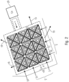
- Fig. 2 shows an exemplary embodiment of an eddy current sensor 1 for a non-destructive testing (NDT) of a substrate, in particular for the NDT of a laminated substrate comprising four plies of carbon fiber reinforced plastic (CFRP).
- NDT non-destructive testing
- CFRP carbon fiber reinforced plastic
- the eddy current sensor comprises an assembly of flat coils, in particular an rectangular assembly of thirty-six flat coils which are arranged in a fixed manner on a rigid substrate layer 21.
- the eddy current sensor 1 comprises a plurality of at least three, in particular nine, eddy current sensor elements.
- one of the eddy current elements is designated by the reference numeral '2' and is depicted in more detail in fig. 1a .
- Fig. 1a shows the eddy current sensor element 2 in a schematic fashion.
- the eddy current sensor element 2 comprises an assembly 3 of at least a first flat coil 4 and a second flat coil 5.
- the assembly 3 further comprises a third flat coil 6 and a fourth flat coil 7.
- the first and the second flat coil 4, 5 have each a triangular shape.
- the assembly 3 has an overall quadrangular, in particular a rectangular, and specifically a square shape.
- All of the four flat coils 4, 5, 6, 7 of the assembly 3 are congruent to each other which means that the dimensional sizes as well as the electric characteristics of the four coils 4, 5, 6, 7 are equal. In the following, only the first flat coil 4 is described in more detail.
- Fig. 3 shows the first flat coil 4 with the triangular shape.
- the flat coil 4 has the shape of an isosceles triangle, with a length 'D' for both of the sceles of the tringle.
- the flat coil 4 has the shape of a right-angled triangle, with an angle of 90° where the two sceles meet.
- the third edge opposite the right angle is termed the 'hypotenuse-edge' of the triangle.
- the flat coil 4 is formed by an electrically conductive wire material deposited on a substrate layer.
- the wire material forms the flat coil 4 with an external length D of the two sceles of approx. 1 mm, a line width I p of approx. 6 ⁇ m, an inter-line space of approx. 3 mm and a number of turns n of 33.
- the depicted triangular-shaped flat coil 4 is designed for an operating frequency of 0.8 MHz to 2.0 MHz, in particular of approximately 1 MHz.
- the first flat coil 4 has two contact points 8, 9 such that a signal, in particular an alternating voltage, can be applied to the flat coil 4.
- a signal in particular an alternating voltage
- the flat coil 4 is excited and an alternating current traverses the wire material of the flat coil 4 causing an alternating electromagnetic field to surround the edges of the flat coil 4.
- the alternating electromagnetic field induces in the substrate under study eddy currents which in turn change the impedance of the flat coil 4. This change in impedance can be sensed in order to gain an information on the substrate under study.
- the flat coil 4 can act as an eddy current sensor unit.
- the application of an operating frequency of approximately 1 MHz has the effect that non-excited adjacent coils, which are ⁇ at rest' with respect to the excited coils, do not influence the measuring result to a significant extent (below, with reference to fig. 7 ).
- the outer contour of the conductor forming the coil 4 renders the coil 4 a triangular shape.
- the coil 4 has the shape of an isosceles triangle, with two edges 10, 11 (the 'sceles') of the triangle having the same length D.
- the flat coil 4 has the shape of a right-angled triangle, since the angle between the sceles 10, 11 is approx. 90°.
- the third edge of the triangle opposite the right angle is called hypotenuse-edge or base 12.
- the eddy current sensor element 2 comprises four coils 4, 5, 6, 7 each of which having the triangular shape described in more detail in fig. 3 with reference to the first flat coil 4.
- the four flat coils 4 to 7 are arranged so that the vertices of each triangle, where the respective right angle is formed, meet at the center of the square, such that the contour of the square is formed by the hypotenuse-edges 4c, 5c, 6c, 7c or bases of each of the triangular coils 4, 5, 6 and 7.
- the assembly 3 comprises the four flat coils 4, 5, 6, 7 such that for any one of the coils, a first edge of this coil is parallel to an edge of a first adjacent coil, and a second edge of this coil is parallel to an edge of a second adjacent coil.
- a first edge 4a of the first flat coil 4 is parallel to an edge 7b of the fourth coil 7 adjacent to the first coil 4
- a second edge 4b is parallel to an edge 5a of the second coil 5 which is adjacent to the first coil 4.
- a first edge 6a of the third coil 6 is parallel to an edge 5b of the second coil 5 adjacent to the third coil 6, and a second edge 6b is parallel to an edge 7a of the fourth coil 7 adjacent to the third coil 6.
- the second edge 4b of the first flat coil 4 is arranged adjacent and parallel to the first edge 5a of the second flat coil 5.
- the assembly 3 of the four coils 4, 5, 6, 7 of the eddy current sensor element 2 can be viewed to be so arranged such that four pairs of mutually parallel edges are formed, namely the edges 4a, 7b between the fourth and the first coil 7, 4, the edges 4b, 5a between the first and the second coil 4, 5, the edges 5b, 6a between the second and the third coil 5, 6, and the edges 6b, 7a between the third and the fourth coil 6, 7.
- the edges 4a, 4b, 5a, 5b, 6a, 6b, 7a, 7b can be viewed as 'inner' edges since they do not contribute to the overall quadrangular, in particular rectangular, more precisely square shape of the assembly 3.
- the square shape of the assembly 3 is due to the hypotenuse-edges 4c, 5c, 6c and 7c of the respective triangular-shaped flat coils 4, 5, 6, 7.
- the eddy current sensor element 2 as depicted in fig. 1a enables to perform a method for operating this eddy current sensor element 2, wherein the method comprises the step of exciting this eddy current element 2 by simultaneously applying a signal, in particular an alternating voltage, to the first coil 4 and to the second coil 5, such that the edge 4b of the first flat coil 4 and the edge 5a of the second flat coil 5, which are arranged adjacent and parallel to each other, are traversed by currents in antiparallel directions.
- a signal in particular an alternating voltage
- the coils 4 and 5 are congruent to each other, it is enabled to apply a voltage of equal polarity and roughly the same absolute value to each of the coils 4 and 5 simultaneously with the effect that the electromagnetic fields along the adjacent and parallel edges 4b, 5a tend to superpose such that the resultant electromagnetic field vanishes to a significant, in particular a maximum extend.
- the surface area which is probed would be that of a coil the contour of which would be delimited by the sceles 5b and 4a of the coils 4 and 5 as well as the outer edges 4c, 5c.
- the eddy current sensor element 2 is enabled to perform the method for operating this eddy current sensor element 2 so as to excite the entire eddy current sensor element 2 by applying simultaneously a signal to each of the coils 4, 5, 6 and 7 such that the resultant electromagnetic fields along the four pairs of mutually parallel adjacent inner edges 7b, 4a and 4b, 5a and 5b, 6a as well as 6b, 7a vanishes to a maximum extent having the effect that the resultant electromagnetic field of the eddy current sensor element 2 is given by the outer edges of the contour of the eddy current sensor element 2, i. e. by the four hypotenuse-edges 4c, 5c, 6c and 7c.
- the excited eddy current sensor element 2 has the effect of a square-shaped coil.
- a signal in particular an alternating voltage of equal polarity and roughly the same absolute value has to be applied simultaneously to each of the coils 4, 5, 6 and 7, which causes the currents in adjacent coils to traverse the coil in the same (in fig. 1a : counter-clockwise) direction.
- the measuring process is completed by sensing the response of the excited substrate by detecting a change in impedance in the flat coils 4, 5, 6, 7 of the eddy current sensor element 2.
- Fig. 1a shows the as-described eddy current sensor element 2 comprises four coils 4, 5, 6, 7 and which can be referred to as a 'four coil eddy current sensor element'.
- fig. 1b shows a second kind of a sensor element 102 which comprises two flat coils and which can be referred to as a 'two coil eddy current sensor element'.
- the first coil 4 is adjacent to a second coil 14.
- Fig. 1b shows an eddy current sensor element 102 for the non-destructive testing of a substrate, comprising an assembly 103 of two flat coils 4, 14, wherein the first flat coil 4 and the second flat coil 14 each have a triangular shape with a first to third coil edge 4a, 4b, 4c, 14a, 14b, 14c.
- the second coil 14 is congruent to the first coil 4 which was described in detail with respect to fig. 3 above, in particular, the second coil 14 has the shape of a right-angled isosceles triangle.
- the hypotenuse edge 4c of the first coil 4 is arranged adjacent and parallel to the hypotenuse edge 14c of the second coil 14 such that the assembly 103 has a quadrangular, in particular a rectangular, more precisely a square shape.
- the two flat coils 4, 14 are such arranged that the hypotenuse edges 4c, 14c of the first coil 4 and of the second coil 14 are parallel.
- the hypotenuse edges 4c, 14c are to be regarded as inner edges since they do not contribute to the shape. Rather, the square shape of the eddy current sensor element 102 is delimited by the outer edges 14a, 14b and 4a, 4b of the triangle-shaped flat coils 4, 14.
- a signal in particular an alternating voltage, is applied to each of the first flat coil 4 and to the second flat coil 14 such that the edge 4c of the first flat coil 4 and the edge 14c of the second flat coil 14 which are arranged adjacent and parallel to each other are traversed by currents in antiparallel directions.
- a signal in particular an alternating voltage
- the resulting electromagnetic field at the parallel and adjacent edges 4c, 14c vanishes to a maximum extent.
- the signal in particular the alternating voltage of equal polarity and about the same absolute value has to be applied simultaneously to each of the coils 4, 14, which causes the currents in the two adjacent coils to traverse the coil in the same (in fig. 1b :clockwise) direction.
- the measuring process is completed by performing the step 'sensing the response of the excited substrate by detecting a change in impedance in the flat coils 4, 14 of the eddy current sensor element 102'.
- Fig. 2 shows two different types of square-shaped eddy current sensor elements, namely a first type comprising four coils, as described above with reference to fig. 1a , and referred to above as 'four coil eddy current sensor element', and a second type, comprising two coils, as described above with reference to fig. 1b , and referred to above as 'two coil eddy current sensor element'.
- the term 'four coil ECSE' refers to the first type of the eddy current sensor element, and the term 'two coil ECSE' to the second type of the eddy current sensor.
- Fig. 2 shows that the eddy current sensor 1 for the non-destructive testing of a substrate comprises a plurality, i. e. more than three, eddy current sensor elements 2, 102, wherein the eddy current sensor elements 2, 102 are arranged in a quadrangular, in particular a rectangular, order adjacent and parallel to each other.
- a second four coil ECSE 2a can be seen as well as a third four coil ECSE 2b.
- the four coil ECSE 2a is adjacent to both, the four coil ECSE 2 and the four coil ECSE 2b.
- a four coil ECSE 2c is adjacent to the four coil ECSE 2 and to the four coil ECSE 2d.
- any two adjacent sensor elements 2, 2a, 2b, 2c, 2d have two parallel edges.
- the edge 5a ( fig. 1a ) is adjacent and parallel to an edge 17 of a triangular shaped coil being part of the four coil ECSE 2a.
- the two coil ECSE 102 is adjacent to another two coil ECSE at the upper right and to still another two coil ECSE at the lower right.
- this element has a parallel edge to the adjacent eddy current sensor element of the same type.
- any two adjacent sensor elements of the same type have two parallel edges.
- the eddy current sensor elements 2, 102 form an array of columns and rows.
- the columns and rows extend along the horizontal and the vertical direction given by the arrows 15, 16.
- the columns and rows extend along a direction at an angle of +45° with respect to the arrow 15 and along a direction at an angle of -45° with respect to the arrow 15, respectively (arrows 18, 19).
- a preferred way of performing the method of operating the eddy current sensor 1 may be exemplified as follows: Starting with the eddy current sensor 1 as depicted in fig. 2 having the two four coil ECSE 2, 2a adjacent to each other extending along the horizontal direction along the arrow 15, as a first step (b) the left ECSE 2 is excited by simultaneously applying a signal to each of the four coils such that current traversing the inner edge of the first coil is antiparallel the current traversing the inner edge of the second coil.
- the electromagnetic fields at the inner edges 4a, 7b, 4b, 5a, 5b, 6y, 6b, 7a superpose such that the respective resultant electromagnetic field is that of a square-shaped coil having the contour delimited by the edges 4c, 5c, 6c and 7c.
- the response of the excited substrate by detecting a change in impedance of the coils 4, 5, 6, 7 of the excited eddy current sensor element 2 is sensed.
- the right ECSE 2a is excited as described above with the step (b), and finally the response of the four coils of the right ECSE 2a is sensed, as described above.
- the surface area under the ECSE 2, 2a has been subsequently sensed, i. e. two adjacent portions of the surface area have been scanned in the direction of the arrow 15 without a relative movement of the eddy current sensor 1 with respect to the surface under study.
- a preferred way of operating the eddy current sensor 1 according a second operating mode may be exemplified as follows: Starting with the eddy current sensor 1 as depicted in fig. 2 having two four coil ECSE 2, 2a adjacent to each other extending along the horizontal direction as indicated by the arrow 15, by simultaneously and jointly exciting each of the two eddy current sensor elements 2, 2a by simultaneously applying a signal to each of the first and the second coil of each of the eddy current sensor elements causing the current traversing an outer edge 5a ( fig.
- the simultaneously and jointly excited adjacent eddy current elements 2, 2a have the effect of a single rectangular eddy current sensor 2' extending in direction of the arrow 15 twice as long as in the perpendicular direction (arrow 16).
- Such an effective rectangular sensor is specifically designed for signals having a preferential orientation along or parallel to the horizontal direction of the arrow 15.
- the first four coil ECSE 2 could be simultaneously and jointly excited with the adjacent four coil ECSE 2c to have the effect of a single rectangular eddy current sensor 2" extending along the vertical direction, as given by the arrow 16.
- this eddy current sensor element together with at least one adjacent two coil ECSE can be simultaneously and jointly be excited to sense the surface under study for defects with a preferential orientation along one of the arrows 18 and 19, respectively.
- the eddy current sensor 1 comprises a control unit 20 which is configured to simultaneously apply a signal, in particular an alternating voltage, to the coils of a sub-group of the coils, wherein the sub-group comprises at least one of the eddy current sensor elements 2, 102.
- the control unit 20 is depicted in fig. 2 and in fig. 3 and has a conductive wire contacting each of the two contacts 8, 9 of each of the coils, as illustrated for the coil 4 in fig. 3 .
- control unit 20 can addresses each of the 36 coils of the eddy current sensor 1 individually or may address a specific sub-group of the coils collectively, in order to apply a signal, in particular an alternating voltage, to the selected sub-groups of the coils or the selected coil, respectively.
- control unit 20 may be configured to scan the eddy current sensor element 2, 102 along the surface under study by subsequently exciting adjacent eddy current sensor elements along one of the directions according to the arrows 18, 19 15 and 16, i. e. according to an angle of 0°, 90°, +45° and -45°.
- an effective sensor 2', 2" can be emulated having a preferred sensitivity to defects in one of the directions 18, 19, 15 and 16.
- the control unit 20 provides adjacent inner edges of the flat coils of the sub-group with currents in antiparallel directions. This was explained in more detail with respect to the fig. 1a, 1b for the eddy current sensor elements 2, 102. Furthermore, with reference to fig. 2 , the effective sensor 2' is constituted by the adjacent eddy current sensor elements 2, 2a. The control unit 20 applies a signal to the coils of the eddy current sensor elements 2, 2a such that for each of the current sensor elements 2, 2a, a current in an antiparallel direction is provided. Furthermore, since the parallel edges 5a, 17 define an inner edge with respect to the effective sensor 2', at these parallel edges 5, 17 currents in an antiparallel or opposite direction are provided.
- the collective outer edge of the flat coils of the sub-group 2' in particular the outer contour which tightly envelopes both the eddy current sensor elements 2, 2a of the sub-group 2', is provided with an effective current which can be envisaged to traverse in a collective circumferential direction along the outer contour of the sub-group 2'.
- the control unit 20 is further configured to subsequently apply a signal to a first sub-group and to a second sub-group, wherein the two sub-groups extend along different direction.
- the first sub-group may be the sub-group 2' ( fig. 2 ) and the second sub-group may be the sub-group 2", with each of the sub-groups 2', 2" comprising two four coil eddy current sensor elements but extending in perpendicular directions.
- the control unit may enable to switch the eddy current sensor 1 with respect to a direction-dependent sensitivity.
- the control unit 20 is further configured to shift the at least one sub-group in at least two direction. If the sub-group is constituted by one single eddy current sensor element 2, 102, this corresponds to the scanning mode operation described above. If the sub-group is constituted by at least two different eddy current sensor elements, e. g. the effective sensor 2' ( fig. 2 ), this shifting may be accomplished by first simultaneously and jointly exciting the eddy current elements 2, 2a (to gain the effective sensor 2') and then to simultaneously and jointly exciting the eddy current elements 2a, 2b in order to provide a shift to the right, along the horizontal direction of the arrow 15. In a similar fashion, the effective sensor 2' may be shifted along the vertical direction, along the direction of the arrow 16.
- the effective sensor 2' may be shifted along the vertical direction, along the direction of the arrow 16.
- control unit 20 is further configured to sense the response of the substrate by detecting a change in impedance of the coils to which the signal has been applied.
- the non-destructive testing of a substrate using eddy currents is based on the distribution and circulation of induced currents in an electrically conductive component of the substrate which is studied.
- the distribution of the induced eddy currents is closely dependent on the profile of the electromagnetic field of excitement.
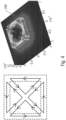
- Fig. 4 shows in the left part a block of four right-angled isosceles triangle shaped coils which form a square shaped block. This block corresponds to the eddy current sensor element 2 that was described above with reference to fig. 1a .
- the four triangular coils of the left part of fig. 4 can be excited in such a way that the resulting electromagnetic field is similar to that of a square coil.
- the fields generated by currents flowing in the diagonal conductor portions are of the same amplitude, but opposite in sign, and hence superpose such as to cancel each other.
- the remaining field is that due to the currents flowing in the external conductor portions. This is shown in fig. 4 , left part, and was explained in more detail above, with reference to fig. 1a . Consequently, as fig.
- the as-described block corresponds to the four coil eddy current sensor element 2 as described above with reference to fig. 1a .
- a four coil eddy current sensor element 2 as described above with reference to fig. 1a is meant.
- a sub-group 202 comprising three square-shaped eddy current sensor elements 202a, 202b, 202c (each comprising a group of four triangular coils, as in fig. 1a explained with respect to the eddy current sensor element 2) can be simultaneously and jointly excited by the application of a signal to each of the eddy current sensor elements 202a, 202b, 202c of the sub-group 202, to have the effective electromagnetic field of a rectangular coil having the same contour as that of the sub-group 202.
- each two adjacent eddy current sensor elements e. g.
- the adjacent eddy current sensor element 202a, 202b) by simultaneously applying a signal, in particular an alternating voltage, to each of four coils of each of the eddy current sensor elements 202a, 202b causes the current traversing an outer (e. g. right) edge of the first eddy current sensor element 202a to be opposite in direction and antiparallel to a current traversing an outer (for this example: left) edge of the second eddy current sensor element 202b adjacent to the first eddy current sensor element 202a.
- the alternating voltages have the same magnitude, the generated electromagnetic fields along the opposing, parallel edges where the two eddy current sensor elements 202a, 202b adjoin will superpose such as to cancel to a large extent.
- the electromagnetic fields may be caused to cancel each other.
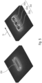
- the magnetic potential vector calculated for a single rectangular coil 250 ( fig. 5 , left) is comparable to the magnetic vector potential for the sub-group 202 comprising the three eddy current sensor elements 202a, 202b 202c arranged adjacent to each other in a row along the horizontal direction (arrow 15, fig. 2 ) when the sensor elements 202a, 202b, 202c are simultaneously and jointly excited by the application of a signal, in particular by the application of an alternating voltage ( fig. 5 , right).
- the overall electromagnetic field behavior for the two systems (left and right part of fig. 5 ) is equivalent.
- the electromagnetic field shows some irregularities which may be due to discontinuities in the geometry of the inductor and to current singularities in the bends of the triangle-shaped coils of which the square-shaped single-element sensor is composed.
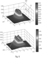
- Fig. 6 shows the calculated electric field magnitudes for a single rectangular coil 250' ( fig. 6 , upper part) in comparison to a sub-group 202' comprising three eddy current sensor elements ( fig. 6 lower part).
- the coil 250' as well as the sub-group 202' extends along a direction perpendicular to the direction of the arrow 15 indicated in fig. 5 .
- the coil 250' as well as the subgroup 202' extends a column, i. e. along the arrow 16 ( fig. 2 ).
- Fig. 7 shows the influence of coils adjacent to the sub-group 202 ( fig. 5 ) comprising the three square-shaped eddy current sensors elements 202a, 202b, 202c.
- the calculation of the distribution of the electric field magnitude surrounding the sub-group 202 was done by numerically neglecting the contribution of the adjacent, non-excited coils (left part) and by taking into account the effect of the adjacent, non-excited coils (right part).
- the adjacent, non-excited coils and non-excited eddy current sensor elements which are to be viewed ⁇ at rest' with respect to the excited eddy current sensor element 202, do not have any significant effect on the spatial configuration of the resulting electromagnetic field or on its amplitude, in particular, when the eddy current sensor is operated at an operating frequency of approximately 1 MHz.
- Fig. 8 shows four different sub-groups obtained by exciting four different sets of eddy current sensor elements of the eddy current multi-element sensor.
- the most fundamental unit is the coil 4 having the shape of a right-angles isosceles triangle which was described above with respect to fig. 3 .
- An arrangement 3 of four such coils 4, 5, 6, 7 forms a square-shaped eddy current sensor element 2 ( fig. 1a )
- three eddy current sensor elements 202a, 202b, 202c arranged adjacent along a row when excited simultaneously and jointly, result in a the sub-group 202 to be excited wherein the sub-group 202 has the effect of a single rectangular multi-element sensor which extends in a horizontal direction (at an angle of 0°, i. e. parallel to the direction of the arrow 15).
- a different set of three eddy current sensor elements 202d, 202b, 202e can be excited by jointly and simultaneously applying a signal to each of them, in order to excite a sub-group 202' which is oriented in a vertical direction, i. e. in a direction along the arrow 16, wherein the sub-group 202' has the effect of a rectangular multi-element sensor which extends in the vertical direction (at an angle of 90° with respect to the arrow 15, fig. 8 , left lower part).
- two adjacent triangle-shaped coils 4, 14 can be simultaneously excited to give a square-shaped eddy current sensor element 102; such an eddy current sensor element 102 has an area which is smaller than the area of the eddy current sensor elements 2, 202a, b, c, d, e.
- the square-shaped sensor element 302 comprising two triangular-shaped coils meeting at the respective parallel hypotenuse-edges is inclined at an angle of +/-45° with respect to the eddy current sensor elements 2, as can be seen in fig. 8 , right column. It can be seen that adjacent two coil eddy current sensor elements 302a, 302b, 302c, 302d are oriented along a first diagonal direction with respect to the vertical and horizontal direction. In particular, the four eddy current sensor elements 302a, 302b, 302c, 302d are arranged at an angle of 45° with respect to the horizontal direction. Furthermore, the two coil eddy current sensor elements 302e, 302f, 302g, 302h are arranged along another diagonal, at an angle of 90° with respect to the first diagonal and at an angle of -45° with respect to the horizontal direction.
- a sub-group 302 by to simultaneously and jointly exciting the four two coil eddy current sensor elements 302a,b,c,d which are arranged in a line along the direction of the arrow 18.
- the excited sub-group 302 is inclined at an angle of 45° with respect to the horizontal direction (arrow 15).
- Each of the sub-groups 302,302' corresponds to a rectangular effective sensor inclined at an angle of +-45° with respect to the horizontal direction.
- the triangular shape of the coils 4 ( fig. 3 ) allows for a great flexibility on desired shapes of an electromagnetic field.
- the eddy current sensor elements comprising two or four coils may be so arranged that they can give a large number of possible electromagnetic field configurations such that a mechanical swiveling, rotation or shifting of the sensor can be avoided.
- the assembly can cover a relative wide inspection area which may reduce the number of scanning operations.
- the eddy current sensor 1 made up of triangle-shaped coils ( fig. 2 ) can be operated such that sub-groups of the coils, wherein a sub-group comprises at least to adjacent eddy current sensor units, can have the electromagnetic field configuration of a single rectangular coil oriented at 0°, 45°, 90° and -45° without recurring to mechanical rotation. This property can be exploited and applied to the measurement of a laminate made of plies of CFRP.
- the modeled system of the laminate made of the plies of CRFP is a stack of four plies oriented at (0°, 45°, 90°, -45°).
- the physical and geometrical characteristics of the modeled system are given by the following table: Parameter Numerical values Unit Laminate Number of plies 4 Fibres orientation 0°, 45°, 90° et -45° [deg] Conductivity ( ⁇ 0 , ⁇ ⁇ , ⁇ ⁇ ) (1.104, 2.102, 10) [S/m] Ply thickness 125 [ ⁇ m] Sensor Number of coils 36 Gap inter-coils 0.08 [min] Lift-off 0.125 [mm] Current intensity 20 [mA] Frequency 1 [MHz]
- Fig. 9 illustrates the calculated distribution of eddy currents induced on a laminate substrate with the above characteristics, by a single rectangular sensor (serving as an inductor) oriented at 0° and its equivalent sub-group 202 comprising the three adjoining eddy current sensor elements 202a, b, c ( fig. 8 , right upper part).
- the sensor (serving as an inductor) has essentially the same outer contour as the sub-group 202.
- Such a sensor is depicted in the left part of fig. 5 and indicated there with the reference numeral '250'.
- the polar diagram of fig. 10 gives the intensity of the measured signal in terms of the rotation angle of the sub-group 202 serving as sensor sensing the response of the induced eddy currents as a change in impedance.
- the four angles of the obtained lobes 300a, b, c, d determine the different fibers orientations whereas their amplitude indicates the position of the ply in the sample under study.
- the comparison between the amplitudes of the peaks of the lobes 300a,b,c,d shows that they are decreasing according to the stacking order of the plies. However, some mismatch as concerns the number of turns and the dimensions of the coils has to be taken into account when comparing the as-obtained results of fig.
- the described embodiment of an eddy current sensor can be envisaged to be a rectangular, in particular square shaped array of identical coils.
- the described embodiment of the eddy current sensor can be envisaged as a single assembly comprising 36 congruent coils, each of which having the shape of a right-angled isosceles triangle such that an angle between one of the sides (sceles) and the hypotenuse (the base) of the triangle is 45°. Since the coils are to be regarded as identical as regards the geometrical as well as to the electrical parameters, in order to determine the best configuration for the optimal functioning of the eddy current sensor, a typical, randomly selected, triangle-shaped coil 4 ( fig. 3 ) is characterized and modelled with respect to its geometrical, electrical and physical characteristics.
- h p is the height of the line
- ⁇ is its electrical resistivity
- ⁇ is the electric permittivity
- ⁇ is the angular frequency
- ⁇ is the study domain
- ⁇ is the magnetic permeability
- B is the magnetic flux density.
- the electromagnetic behavior needs to be qualified.
- the emissive ability has to be calculated. If the coil is used as a receiver, it is necessary to determine its sensitivity and its electrical noise signal.
- the proposed triangular-shaped coil has the versatility to work in emission and reception simultaneously or separately.
- the eddy current sensor element comprising two or four coils as well as a sub-group formed by exciting at least two adjacent eddy current sensor elements has also the versatility to work in emission and reception simultaneously or separately.
- the emissive ability P e is the ratio between the emitted field 'B' and the current 'I' necessary for its emission, according to equation 8:
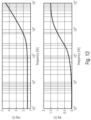
- fig. 12 shows the frequency response of a triangular shaped coil with the parameters of the table given above. It can be seen that the triangular shaped coil can be used as an electromagnetic field sensor up 800 kHz where it shows a strong inductive behavior with a phase upper to 60°. The cut off frequency is much greater than 100 MHz.
- a and V are respectively the magnetic vector potential and electric scalar potential
- ⁇ is the magnetic permeability
- ⁇ II is the electrical conductivity in the fibres direction
- ⁇ J is the conductivity in the transverse direction of the fibres
- ⁇ zz is the conductivity in the direction of the plies stacking.
- the tensor according to equ. (10) represents the anisotropy character of the laminate CFRP model system.
Landscapes
- Chemical & Material Sciences (AREA)
- General Physics & Mathematics (AREA)
- Physics & Mathematics (AREA)
- Electrochemistry (AREA)
- Health & Medical Sciences (AREA)
- Life Sciences & Earth Sciences (AREA)
- Analytical Chemistry (AREA)
- Biochemistry (AREA)
- General Health & Medical Sciences (AREA)
- Chemical Kinetics & Catalysis (AREA)
- Immunology (AREA)
- Pathology (AREA)
- Investigating Or Analyzing Materials By The Use Of Magnetic Means (AREA)
Description
- The invention relates to an eddy current sensor for the non-destructive testing of a substrate as defined in
claim 1, in particular for the testing of a layered substrate made up of plies reinforced by fibers having a preferential direction. Furthermore, the invention relates to a method of operating an eddy current sensor wherein the eddy current sensor comprises a plurality of eddy current sensor elements as defined inclaim 10. Moreover, the invention relates to a use of an eddy current sensor for a non-destructive testing of a substrate as defined inclaim 12. - For the non-destructive testing of materials the use of eddy current sensors is well established. In general terms, an eddy current sensor comprises a flat coil which is arranged in close proximity to the surface of the material to be tested. When a signal, e. g. an alternating voltage, is applied to the contacts at the end of the wire forming the coil, the sensor coil is excited and an alternating electromagnetic field is generated which penetrates into the material to be probed. The alternating electromagnetic field induces in the material eddy currents which themselves are sensed by the coil as a change in the impedance. The surface area which is tested is given by the contour of the coil to which the signal is applied.
- The use of an eddy current sensor is particularly known for the testing of layered materials, such as laminates, in particular for the testing of plies made up of carbon fiber reinforced polymer (CFRP) layers. In this context, an eddy current sensor, which has usually a rectangular shape, is used to study the number as well as the orientation of plies. The relative orientation of the plies is deduced from the orientation of the carbon fibers which reinforce each ply.
- Using an eddy current sensor with a coil of a rectangular shape, the study of a larger portion of the surface of the CRFP requires to shift the coil with respect to the surface under inspection. Furthermore, in order to gain an information on the orientation of the carbon fibers within each ply, the coil has to be rotated parallel to the surface under study. The mechanical rotation involves the intervention of an operator, which reduces the precision of the measurement. Providing an automatic system for moving, in particular for rotating, the eddy current sensor relative to the surface under study, renders the system expensive. In addition to the inaccuracy of a human operator and the costs of an automatic system for shifting the eddy current sensor relative to the surface, both alternatives are disadvantageous in terms of an execution time for the non-destructive testing (NDT).
-
JP S60 141549 U JP S60 141549 U -
US 2003/151402 A1 discloses a device for contactless measurement of a displacement path, especially for the detection of position and movement. The flat coils used have a triangular shape so that two opposed triangular coils form a rectangular shape. In order to measure an eddy current in the coils a target has to move in the direction of arrow D. -
JP 2011 013181 A -
JP H08 29396 A -
US 2008/189968 A1 discloses an arrangement for determining thicknesses and thickness variations. The arrangement comprises an electrically conductive element and guide elements in the form of conveyor rollers. A deflection of the guide elements from one another produces a displacement of the electrically conductive element along a plane defined by a flat coil which results in an eddy current. - To date, the mechanical rotation of the eddy current sensors has been seemed to be without an alternative when probing a material for a direction information, in particular when testing a material like a laminate made up of plies of CFRP.
- It is an object of the invention to provide an eddy current sensor which does not need to be rotated relative to the surface under study in order to gain a directional information.
- According to the invention, this object is accomplished by an eddy current sensor for non-destructive testing of a substrate according to
claim 1. - The eddy current sensor according to the invention comprises a control unit; and a plurality of eddy current sensor elements, with each eddy current sensor elements comprising an assembly of at least a first and a second flat coil, wherein the first flat coil and the second flat coil each have a triangular shape with a first to third coil edge, wherein one of the edges of the first flat coil and one of the edges of the second flat coil are arranged adjacent and parallel to each other, and wherein the assembly has a square shape. The eddy current sensor elements are arranged in a quadrangular order, adjacent and parallel to each other, such that any two adjacent eddy current sensor elements have two parallel edges. The control unit is configured to simultaneously and jointly apply a first signal to the coils of a first sub-group, wherein the first sub group comprises at least two adjacent elements of the plurality of eddy current sensor elements. The control unit is further configured to shift the sub-group in at least two directions by applying a second signal to a second sub-group of the coils, wherein the second sub-group comprises at least two adjacent elements of the plurality of eddy current sensor elements with at least one of the eddy current sensor elements of the second sub-group also forming part of the first sub-group. The first and the second signals being such that adjacent inner edges of the flat coils of each sub-group are provided with currents in anti-parallel directions and such that the collective outer edge of the flat coils of each sub group is provided with a current in a collective circumferential direction. The control unit being further configured to sense the response of the substrate by detecting a change in impedance of the coils to which the signal has been applied
- As still regards the eddy current sensor element according to
claim 1, the invention further envisages a method according toclaim 10 for operating the eddy current sensor element,
the method comprising the step of exciting the eddy current sensor element by simultaneously applying a signal to each of the first and the second coil, such that the edge of the first flat coil and the edge of the second flat coil being arranged adjacent and parallel to each other are traversed by currents in antiparallel directions. - The invention is based on the observation that, providing two parallel electrically conductive wires, when the first wire is traversed with an electrical current of a first direction and the second wire is traversed with an appropriately chosen electrical current in a direction anti-parallel to the first direction, the resulting electromagnetic fields of the two oppositely traversed wires will superpose so that they may cancel each other, to the effect that the resultant electromagnetic field vanishes to a large extent around the two parallel wires.
- As for a single eddy current sensor element, when according to the method for operating this single eddy current element this single eddy current element is excited by simultaneously applying a signal (e. g. an alternating voltage) to the first coil and to the second coil, respectively, such that the edge of the first flat coil and the edge of the second flat coil are arranged adjacent and parallel, these two edges can be traversed by currents in antiparallel directions. In particular, it may be enabled that at the two parallel edges the electromagnetic fields of the two currents may superpose such that the resultant electromagnetic field nearly vanishes. In effect, the electromagnetic field of the excited single eddy current element is that of the remaining sides of the at least two triangular shaped coils, i. e. that of an effective coil having the square shape of the eddy current sensor element.
- In a preferred embodiment each of the at least two flat coils of the eddy current sensor element has the shape of an isosceles triangle.
- For the eddy current sensor element, in a preferred embodiment each of the coils has the shape of a right-angled triangle.
- For the eddy current sensor element, in a preferred embodiment it is envisaged that the assembly comprises two flat coils.
- In particular, it is envisaged for an eddy current sensor element comprising exactly two flat coils each of which having the shape of a right-angled triangle, the two flat coils are arranged such that the hypothenuse-edges of the first coil and of the second coil are parallel.
- In an alternative preferred embodiment, it is envisaged that the assembly comprises four flat coils such that for any one of the coils, a first edge of this coil is parallel to an edge of a first adjacent coil, and a second edge of this coil is parallel to an edge of a second adjacent coil.
- For the eddy current sensor element it is envisaged in a preferred embodiment that all flat coils of the assembly are formed by an electrically conductive wire material deposited on a substrate layer, wherein the wire material forms the flat coil, wherein an external length of two sceles is approx. 1mm, a line width is approx. 6 µm, an interline space is approx.. 3mm and a number of turns is 33, wherein the triangular shaped flat coils are dimensioned for an operating frequency of 0,8 to 2 MHz, in particular of approximately 1 MHz.
- For the eddy current sensor element it an advantage if all of the flat coils of the assembly are congruent to each other. As a consequence, the dimensional characteristics as well as the electrical characteristics of all the flat coils are roughly the same.
- In a preferred embodiment it is envisaged that the eddy current sensor elements form an array of columns and rows. By selectively addressing adjacent eddy current sensor elements a preferred directional information along the columns, along the rows and along a diagonal between the columns and the rows can be obtained.
- As regards the method for operating the eddy current sensor element, in a preferred way to perform the method it is envisaged to perform the step of
- simultaneously and jointly applying a first signal to the coils of a first sub-group, wherein the first sub group comprises at least two adjacent elements of the plurality of eddy current sensor elements,
- shifting the sub-group in at least two directions by applying a second signal to a second sub-group of the coils, wherein the second sub-group comprises at least two adjacent elements of the plurality of eddy current sensor elements with at least one of the eddy current sensor elements of the second sub-group also forming part of the first sub-group;
- the first and the second signals being such that adjacent inner edges of the flat coils of each sub-group are provided with currents in anti-parallel directions and such that the collective outer edge of the flat coils of each sub group is provided with a current in a collective circumferential direction,
- sensing the response of the substrate by detecting a change in impedance of the coils to which the signal has been applied.
- Further features and advantages of the invention will become apparent from the description of at least one preferred embodiment as well as from the appended set of claims.
- In the following, the invention will be described with reference being made to the appended figures.
- Fig. 1a
- is a schematic plan view of an example of an eddy current sensor element which may be used in the eddy current sensor according to the present invention,
- Fig. 1b
- is a schematic plan view of another example of an eddy current sensor element which may be used in the eddy current sensor according to the present invention,
- Fig. 2
- is a perspective schematic view of an embodiment of an eddy current sensor according to the invention, incorporating the eddy current sensor elements of
fig. 1a and fig. 1b , - Fig. 3
- is a schematic plan view of a detail of
fig. 1a and 1b , - Fig. 4
- shows a reproduction of
fig. 1a to demonstrate the current flow upon jointly exciting the four coils of the eddycurrent sensor element 2 offig. 1a (left) and shows a perspective view of the two-dimensional distribution of the magnetic potential vector upon jointly exciting the four coils of the eddy current sensor element 2 (right), - Fig. 5
- shows a perspective view of the two-dimensional distribution of a magnetic field vector calculated for a system of a rectangular coil (a, left) and of a sub-group of the proposed multi-element sensor the sub-group comprising three adjacent eddy current sensor elements as depicted in
fig. 1a arranged in a row (b, right), - Fig. 6
- shows a perspective view of the two-dimensional calculated distribution of the electric field magnitude at the front surface of the load (z = 0), (a) for the rectangular coil of
fig. 5 (left), and, at the right, for the subgroup of the multi-element sensor, the sub-group being comprised of three adjacent eddy current sensor elements offig. 5 (right), - Fig. 7
- shows a plan view of the distribution of the electric field magnitude for a sub-group comprising three eddy current sensor elements arranged in a row, at the front surface of the load (z = 0), (left): without regard to non-exited elements (sigma = 0), and (right): with non-excited elements being physically represented (sigma = 30.6 106 S/m),
- Fig. 8
- shows a plan view of the eddy current sensor with four different field configurations generated by operating the multi-element eddy current sensor, the excited four different sub-groups of the multi-element eddy current sensor being a sensor equivalent to a rectangular coil oriented at 0°, 45°, 90° and -45°,
- Fig. 9
- shows a plan view of the eddy current distribution in different plies of a laminate (0°, 45°, 90°, -45°), at the right column caused by sub-groups of a multi-element sensor, and at the left column caused by a single rectangular coil (3.2 mm x 1 mm),
- Fig. 10
- shows a diagram showing the normalized resistance of the coil as a function of its rotation angle above a laminate of four plies (0°/45°/90°/-45°),
- Fig. 11
- shows an equivalent circuit diagram as a schematic electrical model of a coil in general, and
- Fig. 12
- shows two diagrams with the calculated frequency response of a coil (
fig. 3 ) from which the eddy current sensor is made up. -
Fig. 2 shows an exemplary embodiment of aneddy current sensor 1 for a non-destructive testing (NDT) of a substrate, in particular for the NDT of a laminated substrate comprising four plies of carbon fiber reinforced plastic (CFRP). - The eddy current sensor comprises an assembly of flat coils, in particular an rectangular assembly of thirty-six flat coils which are arranged in a fixed manner on a rigid substrate layer 21. As can be seen, the
eddy current sensor 1 comprises a plurality of at least three, in particular nine, eddy current sensor elements. - In
fig. 2 , one of the eddy current elements is designated by the reference numeral '2' and is depicted in more detail infig. 1a . -
Fig. 1a shows the eddycurrent sensor element 2 in a schematic fashion. As can be seen, the eddycurrent sensor element 2 comprises anassembly 3 of at least a firstflat coil 4 and a secondflat coil 5. In fact, theassembly 3 further comprises a thirdflat coil 6 and a fourthflat coil 7. As can be seen, the first and the secondflat coil assembly 3 has an overall quadrangular, in particular a rectangular, and specifically a square shape. - All of the four
flat coils assembly 3 are congruent to each other which means that the dimensional sizes as well as the electric characteristics of the fourcoils flat coil 4 is described in more detail. -
Fig. 3 shows the firstflat coil 4 with the triangular shape. As can be seen, theflat coil 4 has the shape of an isosceles triangle, with a length 'D' for both of the sceles of the tringle. Furthermore, theflat coil 4 has the shape of a right-angled triangle, with an angle of 90° where the two sceles meet. The third edge opposite the right angle is termed the 'hypotenuse-edge' of the triangle. - The
flat coil 4 is formed by an electrically conductive wire material deposited on a substrate layer. The wire material forms theflat coil 4 with an external length D of the two sceles of approx. 1 mm, a line width Ip of approx. 6 µm, an inter-line space of approx. 3 mm and a number of turns n of 33. The depicted triangular-shapedflat coil 4 is designed for an operating frequency of 0.8 MHz to 2.0 MHz, in particular of approximately 1 MHz. - The first
flat coil 4 has twocontact points flat coil 4. Once an signal, in particular the alternating voltage, is applied to the contact points 8, 9, theflat coil 4 is excited and an alternating current traverses the wire material of theflat coil 4 causing an alternating electromagnetic field to surround the edges of theflat coil 4. The alternating electromagnetic field induces in the substrate under study eddy currents which in turn change the impedance of theflat coil 4. This change in impedance can be sensed in order to gain an information on the substrate under study. - As a consequence, the
flat coil 4 can act as an eddy current sensor unit. The application of an operating frequency of approximately 1 MHz has the effect that non-excited adjacent coils, which are `at rest' with respect to the excited coils, do not influence the measuring result to a significant extent (below, with reference tofig. 7 ). - The outer contour of the conductor forming the
coil 4 renders thecoil 4 a triangular shape. In particular, thecoil 4 has the shape of an isosceles triangle, with twoedges 10, 11 (the 'sceles') of the triangle having the same length D. As can further be seen, theflat coil 4 has the shape of a right-angled triangle, since the angle between thesceles base 12. - As can be seen in
fig. 1a , the eddycurrent sensor element 2 comprises fourcoils fig. 3 with reference to the firstflat coil 4. The fourflat coils 4 to 7 are arranged so that the vertices of each triangle, where the respective right angle is formed, meet at the center of the square, such that the contour of the square is formed by the hypotenuse-edges triangular coils assembly 3 comprises the fourflat coils flat coil 4, afirst edge 4a of the firstflat coil 4 is parallel to anedge 7b of thefourth coil 7 adjacent to thefirst coil 4, and asecond edge 4b is parallel to anedge 5a of thesecond coil 5 which is adjacent to thefirst coil 4. - In a similar fashion, starting with the third
flat coil 6, a first edge 6a of thethird coil 6 is parallel to anedge 5b of thesecond coil 5 adjacent to thethird coil 6, and asecond edge 6b is parallel to anedge 7a of thefourth coil 7 adjacent to thethird coil 6. In particular, thesecond edge 4b of the firstflat coil 4 is arranged adjacent and parallel to thefirst edge 5a of the secondflat coil 5. - The
assembly 3 of the fourcoils current sensor element 2 can be viewed to be so arranged such that four pairs of mutually parallel edges are formed, namely theedges first coil edges second coil edges 5b, 6a between the second and thethird coil edges fourth coil edges assembly 3. In fact, the square shape of theassembly 3 is due to the hypotenuse-edges flat coils - The eddy
current sensor element 2 as depicted infig. 1a enables to perform a method for operating this eddycurrent sensor element 2, wherein the method comprises the step of exciting thiseddy current element 2 by simultaneously applying a signal, in particular an alternating voltage, to thefirst coil 4 and to thesecond coil 5, such that theedge 4b of the firstflat coil 4 and theedge 5a of the secondflat coil 5, which are arranged adjacent and parallel to each other, are traversed by currents in antiparallel directions. In particular, since thecoils coils parallel edges sceles coils outer edges - In particular, starting from the eddy
current sensor element 2 as depicted infig. 1a , it is enabled to perform the method for operating this eddycurrent sensor element 2 so as to excite the entire eddycurrent sensor element 2 by applying simultaneously a signal to each of thecoils inner edges current sensor element 2 is given by the outer edges of the contour of the eddycurrent sensor element 2, i. e. by the four hypotenuse-edges current sensor element 2 has the effect of a square-shaped coil. To achieve this result, a signal, in particular an alternating voltage of equal polarity and roughly the same absolute value has to be applied simultaneously to each of thecoils fig. 1a : counter-clockwise) direction. - Once having excited the eddy
current sensor element 2 as described above, the measuring process is completed by sensing the response of the excited substrate by detecting a change in impedance in theflat coils current sensor element 2. -
Fig. 1a shows the as-described eddycurrent sensor element 2 comprises fourcoils fig. 1b shows a second kind of asensor element 102 which comprises two flat coils and which can be referred to as a 'two coil eddy current sensor element'. As can be seen infig. 1 , thefirst coil 4 is adjacent to asecond coil 14. -
Fig. 1b shows an eddycurrent sensor element 102 for the non-destructive testing of a substrate, comprising anassembly 103 of twoflat coils flat coil 4 and the secondflat coil 14 each have a triangular shape with a first tothird coil edge second coil 14 is congruent to thefirst coil 4 which was described in detail with respect tofig. 3 above, in particular, thesecond coil 14 has the shape of a right-angled isosceles triangle. - As can be seen in
fig. 1b , thehypotenuse edge 4c of thefirst coil 4 is arranged adjacent and parallel to thehypotenuse edge 14c of thesecond coil 14 such that theassembly 103 has a quadrangular, in particular a rectangular, more precisely a square shape. In particular, the twoflat coils first coil 4 and of thesecond coil 14 are parallel. With respect to the square-shaped contour of the eddycurrent sensor element 102, the hypotenuse edges 4c, 14c are to be regarded as inner edges since they do not contribute to the shape. Rather, the square shape of the eddycurrent sensor element 102 is delimited by theouter edges flat coils - Regarding the method for operating the eddy
current sensor element 102, in a preferred way for performing the method, for exciting the eddy current sensor element 102 a signal, in particular an alternating voltage, is applied to each of the firstflat coil 4 and to the secondflat coil 14 such that theedge 4c of the firstflat coil 4 and theedge 14c of the secondflat coil 14 which are arranged adjacent and parallel to each other are traversed by currents in antiparallel directions. In particular, when applying a first voltage to the firstflat coil 4 and a second voltage to the secondflat coil 14, when the voltages have the same absolute value and the same polarities, the resulting electromagnetic field at the parallel andadjacent edges coils fig. 1b :clockwise) direction. - The measuring process is completed by performing the step 'sensing the response of the excited substrate by detecting a change in impedance in the
flat coils -
Fig. 2 shows two different types of square-shaped eddy current sensor elements, namely a first type comprising four coils, as described above with reference tofig. 1a , and referred to above as 'four coil eddy current sensor element', and a second type, comprising two coils, as described above with reference tofig. 1b , and referred to above as 'two coil eddy current sensor element'. - In the following, the term 'four coil ECSE' refers to the first type of the eddy current sensor element, and the term 'two coil ECSE' to the second type of the eddy current sensor.
-
Fig. 2 shows that theeddy current sensor 1 for the non-destructive testing of a substrate comprises a plurality, i. e. more than three, eddycurrent sensor elements current sensor elements - In particular, referring to the four coil ECSE indicated with the
reference numeral 2, to the right a second four coil ECSE 2a can be seen as well as a third four coil ECSE 2b. In particular, along a horizontal direction (arrow 15), the four coil ECSE 2a is adjacent to both, the fourcoil ECSE 2 and the four coil ECSE 2b. - Likewise, in a vertical direction (arrow 16), a four
coil ECSE 2c is adjacent to the fourcoil ECSE 2 and to the fourcoil ECSE 2d. - As can be seen, any two
adjacent sensor elements coil ECSE 2, 2a, theedge 5a (fig. 1a ) is adjacent and parallel to an edge 17 of a triangular shaped coil being part of the four coil ECSE 2a. - Likewise, as can be seen in
fig. 2 , the twocoil ECSE 102 is adjacent to another two coil ECSE at the upper right and to still another two coil ECSE at the lower right. - For the case of both types of eddy
current sensor elements - As can be further seen in
fig. 2 , the eddycurrent sensor elements coil ECSE arrows arrow 15 and along a direction at an angle of -45° with respect to thearrow 15, respectively (arrows 18, 19). - With further reference to
fig. 2 , a preferred way of performing the method of operating theeddy current sensor 1 may be exemplified as follows:
Starting with theeddy current sensor 1 as depicted infig. 2 having the two fourcoil ECSE 2, 2a adjacent to each other extending along the horizontal direction along thearrow 15, as a first step (b) theleft ECSE 2 is excited by simultaneously applying a signal to each of the four coils such that current traversing the inner edge of the first coil is antiparallel the current traversing the inner edge of the second coil. As explained above, with reference tofig. 1a , the electromagnetic fields at theinner edges edges coils current sensor element 2 is sensed. Next, the right ECSE 2a is excited as described above with the step (b), and finally the response of the four coils of the right ECSE 2a is sensed, as described above. In effect, the surface area under theECSE 2, 2a has been subsequently sensed, i. e. two adjacent portions of the surface area have been scanned in the direction of thearrow 15 without a relative movement of theeddy current sensor 1 with respect to the surface under study. - Likewise, by subsequently exciting and sensing the
ECSE arrow 16 can be accomplished. - In a similar fashion, starting from the two-
coil ECSE 102, a scanning in the direction of thearrows - In effect, without moving the
eddy current sensor 1 relative to the surface it is possible to scan the surface in more than three directions independently. This scanning was referred to above as the first mode of operation of theeddy current sensor 1. - Still referring to
fig. 2 , a preferred way of operating theeddy current sensor 1 according a second operating mode may be exemplified as follows:
Starting with theeddy current sensor 1 as depicted infig. 2 having two fourcoil ECSE 2, 2a adjacent to each other extending along the horizontal direction as indicated by thearrow 15, by simultaneously and jointly exciting each of the two eddycurrent sensor elements 2, 2a by simultaneously applying a signal to each of the first and the second coil of each of the eddy current sensor elements causing the current traversing anouter edge 5a (fig. 2 ) of the first eddycurrent sensor element 2 to be antiparallel to a current traversing an outer edge 17 of a second eddy current sensor element 2a adjacent to the first eddycurrent sensor element 2. As a result, the simultaneously and jointly excited adjacent eddycurrent elements 2, 2a have the effect of a single rectangular eddy current sensor 2' extending in direction of thearrow 15 twice as long as in the perpendicular direction (arrow 16). Such an effective rectangular sensor is specifically designed for signals having a preferential orientation along or parallel to the horizontal direction of thearrow 15. - Likewise, the first four
coil ECSE 2 could be simultaneously and jointly excited with the adjacent fourcoil ECSE 2c to have the effect of a single rectangulareddy current sensor 2" extending along the vertical direction, as given by thearrow 16. - In a similar fashion, more than two eddy current sensor elements extending in one direction could be simultaneously and jointly excited.
- Furthermore, starting from the two
coil ECSE 102, this eddy current sensor element together with at least one adjacent two coil ECSE can be simultaneously and jointly be excited to sense the surface under study for defects with a preferential orientation along one of thearrows - In order to perform the operating modes described above, the
eddy current sensor 1 comprises acontrol unit 20 which is configured to simultaneously apply a signal, in particular an alternating voltage, to the coils of a sub-group of the coils, wherein the sub-group comprises at least one of the eddycurrent sensor elements control unit 20 is depicted infig. 2 and infig. 3 and has a conductive wire contacting each of the twocontacts coil 4 infig. 3 . As a consequence, thecontrol unit 20 can addresses each of the 36 coils of theeddy current sensor 1 individually or may address a specific sub-group of the coils collectively, in order to apply a signal, in particular an alternating voltage, to the selected sub-groups of the coils or the selected coil, respectively. - If the sub-group of the coils corresponds to exactly one of the eddy
current sensor elements control unit 20 may be configured to scan the eddycurrent sensor element arrows - If the sub-group of the coils corresponds to two or more of the eddy
current sensor elements effective sensor 2', 2" can be emulated having a preferred sensitivity to defects in one of thedirections - In any instance, the
control unit 20 provides adjacent inner edges of the flat coils of the sub-group with currents in antiparallel directions. This was explained in more detail with respect to thefig. 1a, 1b for the eddycurrent sensor elements fig. 2 , the effective sensor 2' is constituted by the adjacent eddycurrent sensor elements 2, 2a. Thecontrol unit 20 applies a signal to the coils of the eddycurrent sensor elements 2, 2a such that for each of thecurrent sensor elements 2, 2a, a current in an antiparallel direction is provided. Furthermore, since theparallel edges 5a, 17 define an inner edge with respect to the effective sensor 2', at theseparallel edges 5, 17 currents in an antiparallel or opposite direction are provided. As a consequence, the collective outer edge of the flat coils of the sub-group 2', in particular the outer contour which tightly envelopes both the eddycurrent sensor elements 2, 2a of the sub-group 2', is provided with an effective current which can be envisaged to traverse in a collective circumferential direction along the outer contour of the sub-group 2'. - The
control unit 20 is further configured to subsequently apply a signal to a first sub-group and to a second sub-group, wherein the two sub-groups extend along different direction. In particular, the first sub-group may be the sub-group 2' (fig. 2 ) and the second sub-group may be thesub-group 2", with each of thesub-groups 2', 2" comprising two four coil eddy current sensor elements but extending in perpendicular directions. In particular, the control unit may enable to switch theeddy current sensor 1 with respect to a direction-dependent sensitivity. - The
control unit 20 is further configured to shift the at least one sub-group in at least two direction. If the sub-group is constituted by one single eddycurrent sensor element fig. 2 ), this shifting may be accomplished by first simultaneously and jointly exciting the eddycurrent elements 2, 2a (to gain the effective sensor 2') and then to simultaneously and jointly exciting the eddy current elements 2a, 2b in order to provide a shift to the right, along the horizontal direction of thearrow 15. In a similar fashion, the effective sensor 2' may be shifted along the vertical direction, along the direction of thearrow 16. - Furthermore, the
control unit 20 is further configured to sense the response of the substrate by detecting a change in impedance of the coils to which the signal has been applied. - The non-destructive testing of a substrate using eddy currents is based on the distribution and circulation of induced currents in an electrically conductive component of the substrate which is studied. The distribution of the induced eddy currents is closely dependent on the profile of the electromagnetic field of excitement.
-
Fig. 4 shows in the left part a block of four right-angled isosceles triangle shaped coils which form a square shaped block. This block corresponds to the eddycurrent sensor element 2 that was described above with reference tofig. 1a . - Based on the idea that the electromagnetic fields generated by two parallel wires traversed by currents of the same amplitude, but in opposite or antiparallel directions, cancel each other, the four triangular coils of the left part of
fig. 4 can be excited in such a way that the resulting electromagnetic field is similar to that of a square coil. The fields generated by currents flowing in the diagonal conductor portions are of the same amplitude, but opposite in sign, and hence superpose such as to cancel each other. As a result, the remaining field is that due to the currents flowing in the external conductor portions. This is shown infig. 4 , left part, and was explained in more detail above, with reference tofig. 1a . Consequently, asfig. 4 , right part shows, the calculateddistribution 200 of the magnetic potential vector of the eddycurrent sensor element 2 comprising the four triangular-shapedcoils current sensor element 2 as described above with reference tofig. 1a . In the following, when referring to a block, a four coil eddycurrent sensor element 2 as described above with reference tofig. 1a is meant. - Starting with the right part of
fig. 5 , asub-group 202 comprising three square-shaped eddycurrent sensor elements fig. 1a explained with respect to the eddy current sensor element 2) can be simultaneously and jointly excited by the application of a signal to each of the eddycurrent sensor elements sub-group 202, to have the effective electromagnetic field of a rectangular coil having the same contour as that of thesub-group 202. As can be seen, by simultaneously and jointly exciting each two adjacent eddy current sensor elements (e. g. the adjacent eddycurrent sensor element current sensor elements current sensor element 202a to be opposite in direction and antiparallel to a current traversing an outer (for this example: left) edge of the second eddycurrent sensor element 202b adjacent to the first eddycurrent sensor element 202a. If the alternating voltages have the same magnitude, the generated electromagnetic fields along the opposing, parallel edges where the two eddycurrent sensor elements current sensor element - As
fig. 5 shows, the magnetic potential vector calculated for a single rectangular coil 250 (fig. 5 , left) is comparable to the magnetic vector potential for thesub-group 202 comprising the three eddycurrent sensor elements arrow 15,fig. 2 ) when thesensor elements fig. 5 , right). As can be seen, the overall electromagnetic field behavior for the two systems (left and right part offig. 5 ) is equivalent. As for the case of the multi-element sensor comprising three square-shaped blocks offig. 4 (right), the electromagnetic field shows some irregularities which may be due to discontinuities in the geometry of the inductor and to current singularities in the bends of the triangle-shaped coils of which the square-shaped single-element sensor is composed. -
Fig. 6 shows the calculated electric field magnitudes for a single rectangular coil 250' (fig. 6 , upper part) in comparison to a sub-group 202' comprising three eddy current sensor elements (fig. 6 lower part). In comparison tofig. 5 , the coil 250' as well as the sub-group 202' extends along a direction perpendicular to the direction of thearrow 15 indicated infig. 5 . In particular, the coil 250' as well as the subgroup 202' extends a column, i. e. along the arrow 16 (fig. 2 ). -
Fig. 7 shows the influence of coils adjacent to the sub-group 202 (fig. 5 ) comprising the three square-shaped eddycurrent sensors elements sub-group 202 was done by numerically neglecting the contribution of the adjacent, non-excited coils (left part) and by taking into account the effect of the adjacent, non-excited coils (right part). As can be seen, the adjacent, non-excited coils and non-excited eddy current sensor elements, which are to be viewed `at rest' with respect to the excited eddycurrent sensor element 202, do not have any significant effect on the spatial configuration of the resulting electromagnetic field or on its amplitude, in particular, when the eddy current sensor is operated at an operating frequency of approximately 1 MHz. -
Fig. 8 shows four different sub-groups obtained by exciting four different sets of eddy current sensor elements of the eddy current multi-element sensor. The most fundamental unit is thecoil 4 having the shape of a right-angles isosceles triangle which was described above with respect tofig. 3 . Anarrangement 3 of foursuch coils fig. 1a ) - As can be seen in
fig. 8 , left upper part, three eddycurrent sensor elements sub-group 202 to be excited wherein thesub-group 202 has the effect of a single rectangular multi-element sensor which extends in a horizontal direction (at an angle of 0°, i. e. parallel to the direction of the arrow 15). Further, a different set of three eddycurrent sensor elements 202d, 202b, 202e can be excited by jointly and simultaneously applying a signal to each of them, in order to excite a sub-group 202' which is oriented in a vertical direction, i. e. in a direction along thearrow 16, wherein the sub-group 202' has the effect of a rectangular multi-element sensor which extends in the vertical direction (at an angle of 90° with respect to thearrow 15,fig. 8 , left lower part). - Furthermore, as was explained above with respect to
fig. 1b , two adjacent triangle-shapedcoils current sensor element 102; such an eddycurrent sensor element 102 has an area which is smaller than the area of the eddycurrent sensor elements - The square-shaped
sensor element 302 comprising two triangular-shaped coils meeting at the respective parallel hypotenuse-edges is inclined at an angle of +/-45° with respect to the eddycurrent sensor elements 2, as can be seen infig. 8 , right column. It can be seen that adjacent two coil eddycurrent sensor elements current sensor elements current sensor elements - Furthermore, it is envisaged excite a
sub-group 302 by to simultaneously and jointly exciting the four two coil eddycurrent sensor elements 302a,b,c,d which are arranged in a line along the direction of thearrow 18. Theexcited sub-group 302 is inclined at an angle of 45° with respect to the horizontal direction (arrow 15). Additionally, it is envisaged to simultaneously and jointly a sub-group 302' by simultaneously and jointly exciting the four two coil eddycurrent sensor elements 302e,f,g,h such that the sub-group 302' is inclined at an angle of -45° with respect to the horizontal direction. Each of the sub-groups 302,302' corresponds to a rectangular effective sensor inclined at an angle of +-45° with respect to the horizontal direction. - As is apparent from
fig. 8 , the triangular shape of the coils 4 (fig. 3 ) allows for a great flexibility on desired shapes of an electromagnetic field. The eddy current sensor elements comprising two or four coils may be so arranged that they can give a large number of possible electromagnetic field configurations such that a mechanical swiveling, rotation or shifting of the sensor can be avoided. Furthermore, the assembly can cover a relative wide inspection area which may reduce the number of scanning operations. - For different modes of excitation, the
eddy current sensor 1 made up of triangle-shaped coils (fig. 2 ) can be operated such that sub-groups of the coils, wherein a sub-group comprises at least to adjacent eddy current sensor units, can have the electromagnetic field configuration of a single rectangular coil oriented at 0°, 45°, 90° and -45° without recurring to mechanical rotation. This property can be exploited and applied to the measurement of a laminate made of plies of CFRP. - The modeled system of the laminate made of the plies of CRFP is a stack of four plies oriented at (0°, 45°, 90°, -45°). The physical and geometrical characteristics of the modeled system are given by the following table:
Parameter Numerical values Unit Laminate Number of plies 4 Fibres orientation 0°, 45°, 90° et -45° [deg] Conductivity ( σ 0, σ ⊥, σ α) (1.104, 2.102, 10) [S/m] Ply thickness 125 [µm] Sensor Number of coils 36 Gap inter-coils 0.08 [min] Lift-off 0.125 [mm] Current intensity 20 [mA] Frequency 1 [MHz] -
Fig. 9 illustrates the calculated distribution of eddy currents induced on a laminate substrate with the above characteristics, by a single rectangular sensor (serving as an inductor) oriented at 0° and itsequivalent sub-group 202 comprising the three adjoining eddycurrent sensor elements 202a, b, c (fig. 8 , right upper part). The sensor (serving as an inductor) has essentially the same outer contour as thesub-group 202. Such a sensor is depicted in the left part offig. 5 and indicated there with the reference numeral '250'. - It can be noted that the distribution of the induced eddy currents by the two types of sensor in each ply of the laminate is quite identical. This leads to expect an identical response in terms of impedance. Furthermore, the results presented in
fig. 10 prove that the proposed multi-element sensor given by the sub-group 202 (as depicted infig. 8 , left upper part) may detect the orientation of the plies as well as their order of stacking. - The polar diagram of
fig. 10 gives the intensity of the measured signal in terms of the rotation angle of thesub-group 202 serving as sensor sensing the response of the induced eddy currents as a change in impedance. The four angles of the obtained lobes 300a, b, c, d determine the different fibers orientations whereas their amplitude indicates the position of the ply in the sample under study. The comparison between the amplitudes of the peaks of the lobes 300a,b,c,d shows that they are decreasing according to the stacking order of the plies. However, some mismatch as concerns the number of turns and the dimensions of the coils has to be taken into account when comparing the as-obtained results offig. 10 with similar results taken from the literature (e. g. Menana H. (2009): Non-destructive evaluation of the conductivity tensor of a CFRP plate using a rotating eddy current sensor, XIV International Symposium on Electromagnetic Fields. ISEF 2009, Arras - France). It is further noted that there is no significant difference between the peaks at 45° and at 90°; this observation could be explained by the change of sizes of the equivalent rectangular-shaped sub-groups of coils, oriented at 45° and at 90° (seefig. 8 ): In particular, the sub-group 302 (fig. 8 , right upper part) has a slightly higher effective measuring area as compared to the sub-group 202' (fig. 8 , left lower part). - Referring to
fig. 2 , the described embodiment of an eddy current sensor can be envisaged to be a rectangular, in particular square shaped array of identical coils. In particular, the described embodiment of the eddy current sensor can be envisaged as a single assembly comprising 36 congruent coils, each of which having the shape of a right-angled isosceles triangle such that an angle between one of the sides (sceles) and the hypotenuse (the base) of the triangle is 45°. Since the coils are to be regarded as identical as regards the geometrical as well as to the electrical parameters, in order to determine the best configuration for the optimal functioning of the eddy current sensor, a typical, randomly selected, triangle-shaped coil 4 (fig. 3 ) is characterized and modelled with respect to its geometrical, electrical and physical characteristics. - For a geometrical characterization of the triangular shaped coils, the developed or the total length of the wire Itotal and the total effective surface Stotal are given by the
equations 

fig. 3 ). - For an electrical characterization of the triangular-shaped coil, reference is made to
fig. 11 as an electrical model of the coil, in particular as an equivalent circuit diagram of the coil, such that the resistance R, the capacitance C and the inductivity L are given by theequations 3 to 5 as below:


- Where hp is the height of the line, ρ is its electrical resistivity, ε is the electric permittivity, ω is the angular frequency, Ω is the study domain, µ is the magnetic permeability and B is the magnetic flux density. For a determination of the coil inductance L, a census of the stored magnetic energy (equ. 5) was provided via the FE (finite elements) model developed and described below, with reference to equ. (9), (10), below.
- For a physical characterization of the coil, the electromagnetic behavior needs to be qualified. As an electromagnetic sensor, acting as an emitter, the emissive ability has to be calculated. If the coil is used as a receiver, it is necessary to determine its sensitivity and its electrical noise signal. The proposed triangular-shaped coil has the versatility to work in emission and reception simultaneously or separately. As a consequence, the eddy current sensor element comprising two or four coils as well as a sub-group formed by exciting at least two adjacent eddy current sensor elements has also the versatility to work in emission and reception simultaneously or separately.
- The sensitivity S of a coil at a frequency f is according to Faraday-Lenz's law given by equation 6:

- The noise vb of a coil when it is not carrying current is only a thermal agitation noise. This effective voltage at a temperature T and in a measuring frequency range Δf is given by equation 7:

- The emissive ability Pe is the ratio between the emitted field 'B' and the current 'I' necessary for its emission, according to equation 8:

- The relationship between the geometrical, electrical and physical characteristics given above allows to study the influence of each parameter and thus to determine the optimum dimensions of a coil appropriate for a specific application.
- The following table provides the characteristics of the selected triangular-shaped coil that was used to non-destructively evaluate the CFRP:

- Based on the theoretical model as depicted in the equivalent circuit diagram of
fig. 11 for a coil in general,fig. 12 shows the frequency response of a triangular shaped coil with the parameters of the table given above. It can be seen that the triangular shaped coil can be used as an electromagnetic field sensor up 800 kHz where it shows a strong inductive behavior with a phase upper to 60°. The cut off frequency is much greater than 100 MHz. - After the construction of the geometry of the triangular shaped coil and a mesh generation for model the sensor array using the open-source software GMSH, the data were sent to a 3D finite element solver in which were implemented the magneto-dynamics formulation AV-A (equ. 9, below, retained as a governing equation), this mathematical model was retained to describe the electromagnetic behavior of the array of the triangular shaped sensor coils. The calculations were carried out in the harmonic regime. A penalty term was introduced to ensure the uniqueness of the solution (Helifa et al. (2012), Contribution à la simulation du CND par courants de Foucault en vue de la caractérisation des fissures débouchantes. Thèse en sciences et technologies de l'information et de mathématiques, Université de Nantes).

-
A and V are respectively the magnetic vector potential and electric scalar potential, µ is the magnetic permeability and σ is the electrical conductivity tensor given according to the ply orientation by Menana (2009), equation 10:
- Using the characteristics of the selected coil according to the table above and using the model outlined above, in particular with the
equations 9und 10, the results depicted infigures 5 ,6 7 and8 were calculated. Furthermore, using the characteristics of the modeled system (stack of four plies, see table above), the results depicted infigures 9 and10 were numerically obtained. The sensor response, calculated using 3D finite element (FE) modeling, shows the ability of the sensor in particular to evaluate the orientations of plies in CFRP and the order of their stacking. The as-described eddy current sensor, dedicated to non-destructive testing using eddy currents, is an alternative to conventional eddy current sensors which require a mechanical rotation of the sensor in order to evaluate the orientation of plies in CFRP. -
- Grimberg, R. (2005): Eddy current examination of carbon fibres in carbon epoxy composites and Kevlar, The 8th International Conference of the Slovenian Society for Non-Destructive Testing, September 1 - 3, Portoroz, Slovenia,
- Helifa B. (2012): Contribution à la simulation du CND par courants de Foucault en vue de la caractérisation des fissures débouchantes. Thèse en sciences et technologies de l'information et de mathématiques, Université de Nantes.
- Menana H. (2009): Non destructive evaluation of the conductivity tensor of CFRP plate using a rotating eddy current sensor, XIV International Symposium on Electromagnetic Fields. ISEF 2009, Arras - France
- Mook G. (2001): Non-destructive characterization of carbon-fiber reinforced plastics by means of eddy currents. Composites Science and Technology no. 61, p. 865-873
- Ravat C. (2008): Conception de multicapteurs à courants de Foucault et inversion des signaux associés pour le contrôle non destructive. Thèse en sciences et technologies de I'information des télécommunications et des systèmes. Université Paris-Sud II.
- Savin A. (2000): Evaluation of delamination in Carbon Fiber Composites Using the Eddy Current Method. 15th WCNDT, Roma 2000.
Claims (12)
- Eddy current sensor for non-destructive testing of a substrate, comprisinga control unit (20); anda plurality of eddy current sensor elements (2, 2a, 2b, 2c, 2d),
with each eddy current sensor elements (2, 2a, 2b, 2c, 2d) comprising an assembly of at least a first (4) and a second flat coil (14), wherein the first flat coil (4) and the second flat coil (14) each have a triangular shape with a first to third coil edge (4a, 4b, 4c, 14a, 14b, 14c), wherein one of the edges (4b; 4c) of the first flat coil (4) and one of the edges ( 14c) of the second flat coil (14) are arranged adjacent and parallel to each other, and wherein the assembly has a square shape, whereinthe eddy current sensor elements (2, 2a, 2b, 2c, 2d) are arranged in a quadrangular order, adjacent and parallel to each other, such that any two adjacent eddy current sensor elements (2, 2a, 2b, 2c, 2d) have two parallel edges,characterized in that the control unit (20)is configured to simultaneously and jointly apply a first signal to the coils of a first sub-group, wherein the first sub group comprises at least two adjacent elements of the plurality of eddy current sensor elements (2, 2a, 2b, 2c, 2d),wherein the control unit (20) is further configured to shift the sub-group in at least two directions (15, 16) by applying a second signal to a second sub-group of the coils, wherein the second sub-group comprises at least two adjacent elements of the plurality of eddy current sensor elements (2, 2a, 2b, 2c, 2d) with at least one of the eddy current sensor elements (2a, 2c) of the second sub-group (2a,2b; 2c, 2d) also forming part of the first sub-group (2, 2a; 2, 2c);the first and the second signals being such that adjacent inner edges of the flat coils of each sub-group are provided with currents in anti-parallel directions and such that the collective outer edge of the flat coils of each sub group is provided with a current in a collective circumferential direction,the control unit (20) being further configured to sense the response of the substrate (21) by detecting a change in impedance of the coils to which the signal has been applied. - The eddy current sensor according to claim 1, wherein each of the coils (4, 5, 6, 7; 4, 14) has the shape of an isosceles triangle.
- The eddy current sensor according to any one of the claims 1 to 2, wherein each of the coils (4, 5, 6, 7; 4, 14) has the shape of a right-angled triangle.
- The eddy current sensor according to any one of the claims 1 to 3, wherein the assembly (103) comprises two flat coils (4, 14).
- The eddy current sensor according to the claims 3 and 4, wherein the two flat coils (4, 14) are arranged such that the hypotenuse-edges (4c, 14c) of the first coil (4) and of the second coil (14) are parallel.
- The eddy current sensor according to any one of the claims 1 to 3, wherein the assembly (3) comprises four flat coils (4, 5, 6,7) such that for any one of the coils, a first edge of this coil (4) is parallel to an edge of a first adjacent coil, and a second edge of this coil (4) is parallel to an edge of a second adjacent coil.
- The eddy current sensor according to any one of the claims 1 to 6, wherein all flat coils (4, 5, 6, 7; 4, 14) of the assembly (3; 103) are formed by an electrically conductive wire material deposited on a substrate layer, wherein the wire material forms the flat coil , wherein an external length (D) of two sceles is approx. 1mm, a line width (IP) is approx. 6 µm, an interline space is approx. 3mm and a number of turns (N) is 33, wherein the triangular shaped flat coils are dimensioned for an operating frequency of 0,8 to 2 MHz, in particular of approximately 1 MHz.
- The eddy current sensor according to any one of the claims 1 to 7, wherein all of the flat coils (4, 5, 6, 7; 4, 14) of the assembly (3; 103) are congruent to each other, wherein dimensional sizes as well as electric characteristics of the coils are equal.
- The eddy current sensor according to one of the claims 1 to 8, wherein the eddy current sensor elements (2, 2a; 102) form an array of columns and rows.
- Method for operating an eddy current sensor element according to any one of the claims 1 to 8, comprising the step of:simultaneously and jointly applying a first signal to the coils of a first sub-group, wherein the first sub group comprises at least two adjacent elements of the plurality of eddy current sensor elements (2, 2a, 2b, 2c, 2d),shifting the sub-group in at least two directions (15, 16) by applying a second signal to a second sub-group of the coils, wherein the second sub-group comprises at least two adjacent elements of the plurality of eddy current sensor elements (2, 2a, 2b, 2c, 2d) with at least one of the eddy current sensor elements (2a, 2c) of the second sub-group (2a,2b; 2c, 2d) also forming part of the first sub-group (2, 2a; 2, 2c);the first and the second signals being such that adjacent inner edges of the flat coils of each sub-group are provided with currents in anti-parallel directions and such that the collective outer edge of the flat coils of each sub group is provided with a current in a collective circumferential direction,sensing the response of the substrate (21) by detecting a change in impedance of the coils to which the signal has been applied.
- Method for operating an eddy current sensor according to claim 10, wherein two adjacent portions of a surface are scanned without a relative movement of the eddy current sensor (1) with respect to the surface under study.
- Use of an eddy current sensor for non-destructive testing of a substrate according to claims 1 to 9 as an eddy current sensor for a non-destructive testing of a substrate.
Applications Claiming Priority (2)
| Application Number | Priority Date | Filing Date | Title |
|---|---|---|---|
| DE102017208874.5A DE102017208874A1 (en) | 2017-05-24 | 2017-05-24 | Eddy current sensor for non-destructive testing of a substrate |
| PCT/EP2018/063214 WO2018215373A1 (en) | 2017-05-24 | 2018-05-18 | Eddy current sensor comprising triangular coils for non-destructive testing of a substrate |
Publications (2)
| Publication Number | Publication Date |
|---|---|
| EP3631435A1 EP3631435A1 (en) | 2020-04-08 |
| EP3631435B1 true EP3631435B1 (en) | 2025-01-15 |
Family
ID=62528407
Family Applications (1)
| Application Number | Title | Priority Date | Filing Date |
|---|---|---|---|
| EP18729054.9A Active EP3631435B1 (en) | 2017-05-24 | 2018-05-18 | Eddy current sensor comprising triangular coils for non-destructive testing of a substrate |
Country Status (4)
| Country | Link |
|---|---|
| US (1) | US11287398B2 (en) |
| EP (1) | EP3631435B1 (en) |
| DE (1) | DE102017208874A1 (en) |
| WO (1) | WO2018215373A1 (en) |
Families Citing this family (12)
| Publication number | Priority date | Publication date | Assignee | Title |
|---|---|---|---|---|
| CN110988111A (en) * | 2019-11-20 | 2020-04-10 | 厦门大学 | Eddy current array sensor, monitoring device and method for bolt hole edge crack |
| JP7501839B2 (en) * | 2020-08-07 | 2024-06-18 | 株式会社Ihiエアロスペース | Delamination size evaluation system and method |
| CN112525986B (en) * | 2020-12-07 | 2024-04-09 | 兰州理工大学 | Groined plane vortex sensor |
| JP7383196B2 (en) * | 2021-02-18 | 2023-11-17 | 三菱電機株式会社 | Rope inspection device and rope inspection method |
| CN113406193B (en) * | 2021-06-23 | 2024-06-14 | 厦门大学 | Flexible eddy current sensing film based on trapezoidal coil array, detection device and detection method |
| DE112021008267T5 (en) * | 2021-09-24 | 2024-07-18 | Mitsubishi Electric Corporation | ALIGNMENT DIRECTION DETECTION DEVICE |
| US12313592B2 (en) * | 2022-02-28 | 2025-05-27 | Baylor University | Eddy current probe and method for determining ply orientation using eddy current and ultrasonic probes |
| CN115201325B (en) * | 2022-07-22 | 2023-07-21 | 四川德源管道科技股份有限公司 | A multi-layer PCB single excitation multi-reception eddy current detection sensor, system and method |
| US20250123241A1 (en) * | 2023-10-13 | 2025-04-17 | Rtx Corporation | Eddy current probe assembly |
| DE102023136523A1 (en) * | 2023-12-22 | 2025-06-26 | Endress+Hauser Flowtec Ag | Metal detector for classifying conductive objects, method for classifying conductive objects with a metal detector, measuring device for detecting conductive objects in a medium |
| CN118425287B (en) * | 2024-04-29 | 2025-04-15 | 无锡学院 | A defect contour recognition method based on uniform parallel induced current flow characteristics |
| CN119826673B (en) * | 2024-12-25 | 2026-03-20 | 北京理工大学 | An unconventional eddy current detection coil and its optimization method |
Citations (1)
| Publication number | Priority date | Publication date | Assignee | Title |
|---|---|---|---|---|
| US20080189968A1 (en) * | 2005-05-06 | 2008-08-14 | Reto Schletti | Arrangement for Determining Thicknesses and Thickness Variations |
Family Cites Families (7)
| Publication number | Priority date | Publication date | Assignee | Title |
|---|---|---|---|---|
| JPS60141549U (en) * | 1984-02-29 | 1985-09-19 | 株式会社島津製作所 | Eddy current flaw detection equipment |
| JP3051024B2 (en) * | 1994-07-19 | 2000-06-12 | 日本原子力研究所 | Eddy current flaw detection probe |
| DE20011223U1 (en) * | 2000-06-26 | 2000-10-05 | Kindler, Ulrich, Prof. Dr.-Ing., 22143 Hamburg | Device for non-contact displacement measurement, in particular for position and movement detection |
| DE102006031139A1 (en) | 2006-07-03 | 2008-01-10 | Rudolf Schubach | Connecting device for contactless measurement of linear position of rotor, has pair of triangular coils of same surface with form depicts square in former level and another pair of coils of same surface with form arranged in later level |
| US20090091318A1 (en) * | 2007-09-11 | 2009-04-09 | Benoit Lepage | Phased scan eddy current array probe and a phased scanning method which provide complete and continuous coverage of a test surface without mechanical scanning |
| JP5008697B2 (en) * | 2009-07-06 | 2012-08-22 | 中国電力株式会社 | Nondestructive inspection equipment |
| JP2014153325A (en) | 2013-02-13 | 2014-08-25 | Tokai Rika Co Ltd | Eddy current sensor |
-
2017
- 2017-05-24 DE DE102017208874.5A patent/DE102017208874A1/en active Pending
-
2018
- 2018-05-18 WO PCT/EP2018/063214 patent/WO2018215373A1/en not_active Ceased
- 2018-05-18 EP EP18729054.9A patent/EP3631435B1/en active Active
-
2019
- 2019-11-18 US US16/686,470 patent/US11287398B2/en active Active
Patent Citations (1)
| Publication number | Priority date | Publication date | Assignee | Title |
|---|---|---|---|---|
| US20080189968A1 (en) * | 2005-05-06 | 2008-08-14 | Reto Schletti | Arrangement for Determining Thicknesses and Thickness Variations |
Also Published As
| Publication number | Publication date |
|---|---|
| EP3631435A1 (en) | 2020-04-08 |
| US20200088685A1 (en) | 2020-03-19 |
| WO2018215373A1 (en) | 2018-11-29 |
| WO2018215373A8 (en) | 2020-01-02 |
| US11287398B2 (en) | 2022-03-29 |
| DE102017208874A1 (en) | 2018-11-29 |
Similar Documents
| Publication | Publication Date | Title |
|---|---|---|
| US11287398B2 (en) | Eddy current sensor for non-destructive testing of a substrate | |
| US6822443B1 (en) | Sensors and probes for mapping electromagnetic fields | |
| US6504363B1 (en) | Sensor for eddy current testing and method of use thereof | |
| US5554933A (en) | Polar coordinates sensor probe for testing material surrounding fastener holes | |
| JP4662539B2 (en) | Multi-directional distance non-contact measuring instrument | |
| Mook et al. | Non-destructive characterisation of carbon-fibre-reinforced plastics by means of eddy-currents | |
| US8274276B2 (en) | System and method for the non-destructive testing of elongate bodies and their weldbond joints | |
| KR102134492B1 (en) | Differential sensor, inspection system and method for the detection of anomalies in electrically conductive materials | |
| US7518360B2 (en) | Hybrid wound/etched winding constructs for scanning and monitoring | |
| US6911826B2 (en) | Pulsed eddy current sensor probes and inspection methods | |
| US6992482B2 (en) | Magnetic field sensor having a switchable drive current spatial distribution | |
| US20050007108A1 (en) | Probes and methods for detecting defects in metallic structures | |
| US6975108B2 (en) | Methods and devices for eddy current PCB inspection | |
| EP2812685B1 (en) | Apparatus and method for measuring properties of a ferromagnetic material | |
| WO1998012554A1 (en) | Gmr-based detection of defects in conducting materials | |
| US20190369055A1 (en) | Eddy Current Probe with 3-D Excitation Coils | |
| Hughes | High-sensitivity eddy-current testing technology for defect detection in aerospace superalloys | |
| US8358125B2 (en) | Method for determining geometric characteristics of an anomaly in a test object and measuring apparatus for carrying out the method | |
| EP4487127A1 (en) | Eddy current probe and method for determining ply orientation using eddy current and ultrasonic probes | |
| US7304474B2 (en) | Eddy current inspection device with arrays of magnetoresistive sensors | |
| US20060038558A1 (en) | Eddy current inspection device | |
| US20070029997A1 (en) | Test circuit with drive windings and sense elements | |
| EP0198867A1 (en) | Electromagnetic inspection | |
| Megali et al. | EC modelling and enhancement signals in CFRP inspection | |
| Avila et al. | A novel dual modality sensor with sensitivities to permittivity and conductivity |
Legal Events
| Date | Code | Title | Description |
|---|---|---|---|
| STAA | Information on the status of an ep patent application or granted ep patent |
Free format text: STATUS: UNKNOWN |
|
| STAA | Information on the status of an ep patent application or granted ep patent |
Free format text: STATUS: THE INTERNATIONAL PUBLICATION HAS BEEN MADE |
|
| PUAI | Public reference made under article 153(3) epc to a published international application that has entered the european phase |
Free format text: ORIGINAL CODE: 0009012 |
|
| STAA | Information on the status of an ep patent application or granted ep patent |
Free format text: STATUS: REQUEST FOR EXAMINATION WAS MADE |
|
| 17P | Request for examination filed |
Effective date: 20191118 |
|
| AK | Designated contracting states |
Kind code of ref document: A1 Designated state(s): AL AT BE BG CH CY CZ DE DK EE ES FI FR GB GR HR HU IE IS IT LI LT LU LV MC MK MT NL NO PL PT RO RS SE SI SK SM TR |
|
| AX | Request for extension of the european patent |
Extension state: BA ME |
|
| DAV | Request for validation of the european patent (deleted) | ||
| DAX | Request for extension of the european patent (deleted) | ||
| RAP3 | Party data changed (applicant data changed or rights of an application transferred) |
Owner name: FRAUNHOFER-GESELLSCHAFT ZUR FOERDERUNG DER ANGEWANDTEN FORSCHUNG E.V. |
|
| STAA | Information on the status of an ep patent application or granted ep patent |
Free format text: STATUS: EXAMINATION IS IN PROGRESS |
|
| 17Q | First examination report despatched |
Effective date: 20220630 |
|
| GRAP | Despatch of communication of intention to grant a patent |
Free format text: ORIGINAL CODE: EPIDOSNIGR1 |
|
| STAA | Information on the status of an ep patent application or granted ep patent |
Free format text: STATUS: GRANT OF PATENT IS INTENDED |
|
| INTG | Intention to grant announced |
Effective date: 20240812 |
|
| GRAS | Grant fee paid |
Free format text: ORIGINAL CODE: EPIDOSNIGR3 |
|
| GRAA | (expected) grant |
Free format text: ORIGINAL CODE: 0009210 |
|
| STAA | Information on the status of an ep patent application or granted ep patent |
Free format text: STATUS: THE PATENT HAS BEEN GRANTED |
|
| AK | Designated contracting states |
Kind code of ref document: B1 Designated state(s): AL AT BE BG CH CY CZ DE DK EE ES FI FR GB GR HR HU IE IS IT LI LT LU LV MC MK MT NL NO PL PT RO RS SE SI SK SM TR |
|
| REG | Reference to a national code |
Ref country code: CH Ref legal event code: EP Ref country code: GB Ref legal event code: FG4D |
|
| P01 | Opt-out of the competence of the unified patent court (upc) registered |
Free format text: CASE NUMBER: APP_65949/2024 Effective date: 20241213 |
|
| REG | Reference to a national code |
Ref country code: DE Ref legal event code: R096 Ref document number: 602018078498 Country of ref document: DE |
|
| REG | Reference to a national code |
Ref country code: IE Ref legal event code: FG4D |
|
| REG | Reference to a national code |
Ref country code: NL Ref legal event code: MP Effective date: 20250115 |
|
| PG25 | Lapsed in a contracting state [announced via postgrant information from national office to epo] |
Ref country code: NL Free format text: LAPSE BECAUSE OF FAILURE TO SUBMIT A TRANSLATION OF THE DESCRIPTION OR TO PAY THE FEE WITHIN THE PRESCRIBED TIME-LIMIT Effective date: 20250115 |
|
| PG25 | Lapsed in a contracting state [announced via postgrant information from national office to epo] |
Ref country code: RS Free format text: LAPSE BECAUSE OF FAILURE TO SUBMIT A TRANSLATION OF THE DESCRIPTION OR TO PAY THE FEE WITHIN THE PRESCRIBED TIME-LIMIT Effective date: 20250415 |
|
| PG25 | Lapsed in a contracting state [announced via postgrant information from national office to epo] |
Ref country code: FI Free format text: LAPSE BECAUSE OF FAILURE TO SUBMIT A TRANSLATION OF THE DESCRIPTION OR TO PAY THE FEE WITHIN THE PRESCRIBED TIME-LIMIT Effective date: 20250115 |
|
| PG25 | Lapsed in a contracting state [announced via postgrant information from national office to epo] |
Ref country code: PL Free format text: LAPSE BECAUSE OF FAILURE TO SUBMIT A TRANSLATION OF THE DESCRIPTION OR TO PAY THE FEE WITHIN THE PRESCRIBED TIME-LIMIT Effective date: 20250115 |
|
| PGFP | Annual fee paid to national office [announced via postgrant information from national office to epo] |
Ref country code: DE Payment date: 20250519 Year of fee payment: 8 |
|
| PG25 | Lapsed in a contracting state [announced via postgrant information from national office to epo] |
Ref country code: ES Free format text: LAPSE BECAUSE OF FAILURE TO SUBMIT A TRANSLATION OF THE DESCRIPTION OR TO PAY THE FEE WITHIN THE PRESCRIBED TIME-LIMIT Effective date: 20250115 |
|
| PGFP | Annual fee paid to national office [announced via postgrant information from national office to epo] |
Ref country code: GB Payment date: 20250522 Year of fee payment: 8 |
|
| REG | Reference to a national code |
Ref country code: LT Ref legal event code: MG9D |
|
| PG25 | Lapsed in a contracting state [announced via postgrant information from national office to epo] |
Ref country code: IS Free format text: LAPSE BECAUSE OF FAILURE TO SUBMIT A TRANSLATION OF THE DESCRIPTION OR TO PAY THE FEE WITHIN THE PRESCRIBED TIME-LIMIT Effective date: 20250515 Ref country code: NO Free format text: LAPSE BECAUSE OF FAILURE TO SUBMIT A TRANSLATION OF THE DESCRIPTION OR TO PAY THE FEE WITHIN THE PRESCRIBED TIME-LIMIT Effective date: 20250415 |
|
| REG | Reference to a national code |
Ref country code: AT Ref legal event code: MK05 Ref document number: 1760138 Country of ref document: AT Kind code of ref document: T Effective date: 20250115 |
|
| PG25 | Lapsed in a contracting state [announced via postgrant information from national office to epo] |
Ref country code: HR Free format text: LAPSE BECAUSE OF FAILURE TO SUBMIT A TRANSLATION OF THE DESCRIPTION OR TO PAY THE FEE WITHIN THE PRESCRIBED TIME-LIMIT Effective date: 20250115 |
|
| PG25 | Lapsed in a contracting state [announced via postgrant information from national office to epo] |
Ref country code: PT Free format text: LAPSE BECAUSE OF FAILURE TO SUBMIT A TRANSLATION OF THE DESCRIPTION OR TO PAY THE FEE WITHIN THE PRESCRIBED TIME-LIMIT Effective date: 20250515 Ref country code: LV Free format text: LAPSE BECAUSE OF FAILURE TO SUBMIT A TRANSLATION OF THE DESCRIPTION OR TO PAY THE FEE WITHIN THE PRESCRIBED TIME-LIMIT Effective date: 20250115 |
|
| PGFP | Annual fee paid to national office [announced via postgrant information from national office to epo] |
Ref country code: FR Payment date: 20250523 Year of fee payment: 8 |
|
| PG25 | Lapsed in a contracting state [announced via postgrant information from national office to epo] |
Ref country code: GR Free format text: LAPSE BECAUSE OF FAILURE TO SUBMIT A TRANSLATION OF THE DESCRIPTION OR TO PAY THE FEE WITHIN THE PRESCRIBED TIME-LIMIT Effective date: 20250416 Ref country code: BG Free format text: LAPSE BECAUSE OF FAILURE TO SUBMIT A TRANSLATION OF THE DESCRIPTION OR TO PAY THE FEE WITHIN THE PRESCRIBED TIME-LIMIT Effective date: 20250115 |
|
| PG25 | Lapsed in a contracting state [announced via postgrant information from national office to epo] |
Ref country code: AT Free format text: LAPSE BECAUSE OF FAILURE TO SUBMIT A TRANSLATION OF THE DESCRIPTION OR TO PAY THE FEE WITHIN THE PRESCRIBED TIME-LIMIT Effective date: 20250115 |
|
| PG25 | Lapsed in a contracting state [announced via postgrant information from national office to epo] |
Ref country code: SE Free format text: LAPSE BECAUSE OF FAILURE TO SUBMIT A TRANSLATION OF THE DESCRIPTION OR TO PAY THE FEE WITHIN THE PRESCRIBED TIME-LIMIT Effective date: 20250115 |
|
| PG25 | Lapsed in a contracting state [announced via postgrant information from national office to epo] |
Ref country code: SM Free format text: LAPSE BECAUSE OF FAILURE TO SUBMIT A TRANSLATION OF THE DESCRIPTION OR TO PAY THE FEE WITHIN THE PRESCRIBED TIME-LIMIT Effective date: 20250115 |
|
| PG25 | Lapsed in a contracting state [announced via postgrant information from national office to epo] |
Ref country code: DK Free format text: LAPSE BECAUSE OF FAILURE TO SUBMIT A TRANSLATION OF THE DESCRIPTION OR TO PAY THE FEE WITHIN THE PRESCRIBED TIME-LIMIT Effective date: 20250115 |
|
| PG25 | Lapsed in a contracting state [announced via postgrant information from national office to epo] |
Ref country code: IT Free format text: LAPSE BECAUSE OF FAILURE TO SUBMIT A TRANSLATION OF THE DESCRIPTION OR TO PAY THE FEE WITHIN THE PRESCRIBED TIME-LIMIT Effective date: 20250115 |
|
| REG | Reference to a national code |
Ref country code: DE Ref legal event code: R097 Ref document number: 602018078498 Country of ref document: DE |
|
| PG25 | Lapsed in a contracting state [announced via postgrant information from national office to epo] |
Ref country code: CZ Free format text: LAPSE BECAUSE OF FAILURE TO SUBMIT A TRANSLATION OF THE DESCRIPTION OR TO PAY THE FEE WITHIN THE PRESCRIBED TIME-LIMIT Effective date: 20250115 Ref country code: EE Free format text: LAPSE BECAUSE OF FAILURE TO SUBMIT A TRANSLATION OF THE DESCRIPTION OR TO PAY THE FEE WITHIN THE PRESCRIBED TIME-LIMIT Effective date: 20250115 |
|
| PG25 | Lapsed in a contracting state [announced via postgrant information from national office to epo] |
Ref country code: RO Free format text: LAPSE BECAUSE OF FAILURE TO SUBMIT A TRANSLATION OF THE DESCRIPTION OR TO PAY THE FEE WITHIN THE PRESCRIBED TIME-LIMIT Effective date: 20250115 |
|
| PG25 | Lapsed in a contracting state [announced via postgrant information from national office to epo] |
Ref country code: SK Free format text: LAPSE BECAUSE OF FAILURE TO SUBMIT A TRANSLATION OF THE DESCRIPTION OR TO PAY THE FEE WITHIN THE PRESCRIBED TIME-LIMIT Effective date: 20250115 |
|
| PLBE | No opposition filed within time limit |
Free format text: ORIGINAL CODE: 0009261 |
|
| STAA | Information on the status of an ep patent application or granted ep patent |
Free format text: STATUS: NO OPPOSITION FILED WITHIN TIME LIMIT |
|
| REG | Reference to a national code |
Ref country code: CH Ref legal event code: L10 Free format text: ST27 STATUS EVENT CODE: U-0-0-L10-L00 (AS PROVIDED BY THE NATIONAL OFFICE) Effective date: 20251126 |
|
| REG | Reference to a national code |
Ref country code: CH Ref legal event code: H13 Free format text: ST27 STATUS EVENT CODE: U-0-0-H10-H13 (AS PROVIDED BY THE NATIONAL OFFICE) Effective date: 20251223 |
|
| 26N | No opposition filed |
Effective date: 20251016 |
|
| PG25 | Lapsed in a contracting state [announced via postgrant information from national office to epo] |
Ref country code: LU Free format text: LAPSE BECAUSE OF NON-PAYMENT OF DUE FEES Effective date: 20250518 |
|
| PG25 | Lapsed in a contracting state [announced via postgrant information from national office to epo] |
Ref country code: CH Free format text: LAPSE BECAUSE OF NON-PAYMENT OF DUE FEES Effective date: 20250531 |
|
| REG | Reference to a national code |
Ref country code: BE Ref legal event code: MM Effective date: 20250531 |
|
| PG25 | Lapsed in a contracting state [announced via postgrant information from national office to epo] |
Ref country code: MC Free format text: LAPSE BECAUSE OF FAILURE TO SUBMIT A TRANSLATION OF THE DESCRIPTION OR TO PAY THE FEE WITHIN THE PRESCRIBED TIME-LIMIT Effective date: 20250115 |
|
| PG25 | Lapsed in a contracting state [announced via postgrant information from national office to epo] |
Ref country code: IE Free format text: LAPSE BECAUSE OF NON-PAYMENT OF DUE FEES Effective date: 20250518 |
|
| PG25 | Lapsed in a contracting state [announced via postgrant information from national office to epo] |
Ref country code: BE Free format text: LAPSE BECAUSE OF NON-PAYMENT OF DUE FEES Effective date: 20250531 |