EP3631205B1 - Wind turbine fault detection using acoustic, vibration, and electrical signals - Google Patents
Wind turbine fault detection using acoustic, vibration, and electrical signals Download PDFInfo
- Publication number
- EP3631205B1 EP3631205B1 EP18810438.4A EP18810438A EP3631205B1 EP 3631205 B1 EP3631205 B1 EP 3631205B1 EP 18810438 A EP18810438 A EP 18810438A EP 3631205 B1 EP3631205 B1 EP 3631205B1
- Authority
- EP
- European Patent Office
- Prior art keywords
- signal
- fault
- vibration
- acoustic
- data
- Prior art date
- Legal status (The legal status is an assumption and is not a legal conclusion. Google has not performed a legal analysis and makes no representation as to the accuracy of the status listed.)
- Active
Links
- 238000001514 detection method Methods 0.000 title description 9
- 238000000034 method Methods 0.000 claims description 76
- 238000005259 measurement Methods 0.000 claims description 25
- 230000003595 spectral effect Effects 0.000 claims description 7
- 230000009471 action Effects 0.000 claims description 6
- 230000008569 process Effects 0.000 claims description 6
- 238000010586 diagram Methods 0.000 description 9
- 238000004458 analytical method Methods 0.000 description 8
- 238000012423 maintenance Methods 0.000 description 8
- 238000001228 spectrum Methods 0.000 description 8
- 238000004891 communication Methods 0.000 description 5
- 238000012544 monitoring process Methods 0.000 description 5
- 238000005516 engineering process Methods 0.000 description 4
- 238000000605 extraction Methods 0.000 description 4
- 230000002950 deficient Effects 0.000 description 3
- 238000012545 processing Methods 0.000 description 3
- 206010062544 Tooth fracture Diseases 0.000 description 2
- 230000000694 effects Effects 0.000 description 2
- 238000001914 filtration Methods 0.000 description 2
- 230000006870 function Effects 0.000 description 2
- 238000012986 modification Methods 0.000 description 2
- 230000004048 modification Effects 0.000 description 2
- 230000003449 preventive effect Effects 0.000 description 2
- 238000005070 sampling Methods 0.000 description 2
- 238000004088 simulation Methods 0.000 description 2
- 101100129500 Caenorhabditis elegans max-2 gene Proteins 0.000 description 1
- 238000000692 Student's t-test Methods 0.000 description 1
- 230000005856 abnormality Effects 0.000 description 1
- 238000004364 calculation method Methods 0.000 description 1
- 230000015556 catabolic process Effects 0.000 description 1
- 230000007547 defect Effects 0.000 description 1
- 238000006731 degradation reaction Methods 0.000 description 1
- 238000013461 design Methods 0.000 description 1
- 238000006073 displacement reaction Methods 0.000 description 1
- 230000036541 health Effects 0.000 description 1
- 230000000750 progressive effect Effects 0.000 description 1
- 230000009467 reduction Effects 0.000 description 1
- 230000008439 repair process Effects 0.000 description 1
- 238000010183 spectrum analysis Methods 0.000 description 1
- 238000012353 t test Methods 0.000 description 1
- 238000012360 testing method Methods 0.000 description 1
Images


Classifications
-
- G—PHYSICS
- G01—MEASURING; TESTING
- G01R—MEASURING ELECTRIC VARIABLES; MEASURING MAGNETIC VARIABLES
- G01R31/00—Arrangements for testing electric properties; Arrangements for locating electric faults; Arrangements for electrical testing characterised by what is being tested not provided for elsewhere
- G01R31/34—Testing dynamo-electric machines
- G01R31/343—Testing dynamo-electric machines in operation
-
- F—MECHANICAL ENGINEERING; LIGHTING; HEATING; WEAPONS; BLASTING
- F03—MACHINES OR ENGINES FOR LIQUIDS; WIND, SPRING, OR WEIGHT MOTORS; PRODUCING MECHANICAL POWER OR A REACTIVE PROPULSIVE THRUST, NOT OTHERWISE PROVIDED FOR
- F03D—WIND MOTORS
- F03D7/00—Controlling wind motors
- F03D7/02—Controlling wind motors the wind motors having rotation axis substantially parallel to the air flow entering the rotor
- F03D7/0296—Controlling wind motors the wind motors having rotation axis substantially parallel to the air flow entering the rotor to prevent, counteract or reduce noise emissions
-
- F—MECHANICAL ENGINEERING; LIGHTING; HEATING; WEAPONS; BLASTING
- F03—MACHINES OR ENGINES FOR LIQUIDS; WIND, SPRING, OR WEIGHT MOTORS; PRODUCING MECHANICAL POWER OR A REACTIVE PROPULSIVE THRUST, NOT OTHERWISE PROVIDED FOR
- F03D—WIND MOTORS
- F03D17/00—Monitoring or testing of wind motors, e.g. diagnostics
-
- G—PHYSICS
- G01—MEASURING; TESTING
- G01H—MEASUREMENT OF MECHANICAL VIBRATIONS OR ULTRASONIC, SONIC OR INFRASONIC WAVES
- G01H1/00—Measuring characteristics of vibrations in solids by using direct conduction to the detector
- G01H1/003—Measuring characteristics of vibrations in solids by using direct conduction to the detector of rotating machines
-
- G—PHYSICS
- G01—MEASURING; TESTING
- G01H—MEASUREMENT OF MECHANICAL VIBRATIONS OR ULTRASONIC, SONIC OR INFRASONIC WAVES
- G01H3/00—Measuring characteristics of vibrations by using a detector in a fluid
- G01H3/10—Amplitude; Power
- G01H3/12—Amplitude; Power by electric means
-
- F—MECHANICAL ENGINEERING; LIGHTING; HEATING; WEAPONS; BLASTING
- F05—INDEXING SCHEMES RELATING TO ENGINES OR PUMPS IN VARIOUS SUBCLASSES OF CLASSES F01-F04
- F05B—INDEXING SCHEME RELATING TO WIND, SPRING, WEIGHT, INERTIA OR LIKE MOTORS, TO MACHINES OR ENGINES FOR LIQUIDS COVERED BY SUBCLASSES F03B, F03D AND F03G
- F05B2270/00—Control
- F05B2270/30—Control parameters, e.g. input parameters
- F05B2270/333—Noise or sound levels
-
- F—MECHANICAL ENGINEERING; LIGHTING; HEATING; WEAPONS; BLASTING
- F05—INDEXING SCHEMES RELATING TO ENGINES OR PUMPS IN VARIOUS SUBCLASSES OF CLASSES F01-F04
- F05B—INDEXING SCHEME RELATING TO WIND, SPRING, WEIGHT, INERTIA OR LIKE MOTORS, TO MACHINES OR ENGINES FOR LIQUIDS COVERED BY SUBCLASSES F03B, F03D AND F03G
- F05B2270/00—Control
- F05B2270/30—Control parameters, e.g. input parameters
- F05B2270/334—Vibration measurements
-
- G—PHYSICS
- G01—MEASURING; TESTING
- G01R—MEASURING ELECTRIC VARIABLES; MEASURING MAGNETIC VARIABLES
- G01R31/00—Arrangements for testing electric properties; Arrangements for locating electric faults; Arrangements for electrical testing characterised by what is being tested not provided for elsewhere
- G01R31/34—Testing dynamo-electric machines
-
- Y—GENERAL TAGGING OF NEW TECHNOLOGICAL DEVELOPMENTS; GENERAL TAGGING OF CROSS-SECTIONAL TECHNOLOGIES SPANNING OVER SEVERAL SECTIONS OF THE IPC; TECHNICAL SUBJECTS COVERED BY FORMER USPC CROSS-REFERENCE ART COLLECTIONS [XRACs] AND DIGESTS
- Y02—TECHNOLOGIES OR APPLICATIONS FOR MITIGATION OR ADAPTATION AGAINST CLIMATE CHANGE
- Y02E—REDUCTION OF GREENHOUSE GAS [GHG] EMISSIONS, RELATED TO ENERGY GENERATION, TRANSMISSION OR DISTRIBUTION
- Y02E10/00—Energy generation through renewable energy sources
- Y02E10/70—Wind energy
- Y02E10/72—Wind turbines with rotation axis in wind direction
Definitions
- the present disclosure relates generally to wind turbines, and more particularly to methods and systems for improved detection of faults in various components of drivetrains in wind turbines.
- a wind turbine includes a rotor that includes a rotatable hub assembly having multiple blades.
- the blades transform wind energy into a mechanical rotational torque that in turn drives a drivetrain coupled to an electrical generator.
- electrical generators, motors and the drive train in a wind turbine may generate torsional and radial vibrations due to presence of defective components such as bearings, gears, or the like.
- vibration analysis of components in a wind turbine can be performed to monitor operating conditions. For example, mechanical faults in wind turbines having a drive train may generate vibrations at the rotor rotating frequency. However, it has been found that vibration signals may not detect all types of faults associated with the various components of the drive train.
- Documents US 2015/116131 A1 and US 2015/292484 A1 relate to monitoring systems that diagnoses an abnormality of an apparatus provided in a wind turbine or a drive train health metric.
- Document US 9576445 B2 relates to systems for outputting haptic effects.
- Other examples of prior art solutions are available in document XP093020224.
- the present invention is directed to a method for determining a fault condition for a component of a drivetrain in a wind turbine according to claim 1 and a control system according to claim 10.
- One example aspect of the present disclosure is directed to a method for determining a fault condition for a component of a drivetrain in a wind turbine.
- the method can include receiving an acoustic signal from an acoustic signal measuring device.
- the method can further include receiving a vibration signal from a vibration signal measuring device.
- the method can further include analyzing the acoustic signal to determine an analyzed acoustic signal.
- the method can further include analyzing the vibration signal to determine an analyzed vibration signal.
- the method can further include determining a fault condition for the component based at least in part on the analyzed acoustic signal and analyzed vibration signal.
- the control system can include an acoustic signal measurement device, an electrical signal measurement device, a vibration signal measurement device, and one or more processors and one or more memory devices configured to store instructions that when executed by the one or more processors cause the one or more processors to perform operations.
- the operations can include receiving first data indicative of an acoustic signal from the acoustic signal measurement device.
- the operations can further include receiving second data indicative of a vibration signal from the vibration signal measurement device.
- the operations can further include receiving third data indicative of an electrical signal from the electrical signal measurement device.
- the operations can further include processing the first data, second data, and third data to determine a first processed data, a second processed data, and a third processed data.
- the operations can further include determining a fault condition based at least in part on the first processed data, the second processed data, and the third processed data.
- the wind turbine system can include a wind turbine, which can include a drivetrain.
- the drivetrain can include a plurality of components.
- the plurality of components can include a plurality of bearings, races, and gears.
- the wind turbine system can also include an acoustic signal measurement device, an electric signal measurement device, a vibration signal measurement device, and one or more processors and one or more memory devices configured to store instructions that when executed by the one or more processors cause the one or more processors to perform operations.
- the operations can include receiving first data indicative of an acoustic signal from the acoustic signal measurement device.
- the operations can further include receiving second data indicative of a vibration signal from the vibration signal measurement device.
- the operations can further include receiving third data indicative of an electrical signal from the electrical signal measurement device.
- the operations can further include processing the first data, second data, and third data to determine a first processed data, a second processed data, and a third processed data.
- the operations can further include determining a fault condition based at least in part on the first processed data, the second processed data, and the third processed data.
- a wind turbine system can include a drivetrain, which can include a plurality of components, such as gears, bearings, races, or other components.
- the wind turbine system can include a control system, such as a control system with one or more processors and one or more memory devices.
- the one or more processors can be configured to receive signals from one or more acoustic signal measuring devices, vibration signal measuring devices, and electrical signal measuring devices.
- a method for determining a fault condition can include receiving an acoustic signal from an acoustic signal measuring device and receiving a vibration signal from a vibration signal device.
- a processor can be configured to receive data indicative of an acoustic signal and data indicative of a vibration signal.
- An acoustic signal measuring device can be, for example, a microphone or an array of microphones positioned proximate to a an examined mechanical device, such as a drivetrain in a wind turbine.
- a vibration signal measuring device can be, for example, an accelerometer or other vibration signal measuring device positioned on a gearbox of the wind turbine.
- the method can also include analyzing the acoustic signal to determine an analyzed acoustic signal, and analyzing the vibration signal to determine an analyzed vibration signal.
- the processor can be configured to perform the signal analysis.
- the method can also include determining a fault condition based at least in part on the analyzed acoustic signal and the analyzed vibration signal.
- analyzing the acoustic signal to determine an analyzed acoustic signal can include extracting an envelope of the signal and estimating a power spectral density ("PSD") for the acoustic signal.
- PSD power spectral density
- an envelope can be extracted from the vibration signal, and a PSD for the envelope of the vibration signal can be estimated.
- a fault condition can be determined based on the analyzed signals. For example, the PSD of the envelope of the the analyzed the envelope of acoustic signal can be compared to a first threshold at a signature fault frequency, and the PSD of the envelope of the analyzed vibration signal can be compared to a second threshold at the signature fault frequency.
- the signature fault frequency can be, for example, a frequency associated with a specific type of fault, such as a chipped tooth on a gear, a defective ball bearing, or a worn component.
- the signature fault frequencies can be one or more predicted fault frequencies, wherein the predicted fault frequency is a frequency where an analyzed signal is expected to exhibit a particular characteristic, such as an elevated energy level due to the nature of the fault.
- a predicted fault frequency can be calculated based on a shaft rotation frequency or a mesh frequency for a gear.
- a fault condition can be determined to exist when the analyzed acoustic signal exceeds the first threshold, and the analyzed vibration signal exceeds the second threshold.
- the method can further include receiving an electrical signal from an electrical signal measuring device.
- a voltage sensor or a current sensor can be configured to measure an electrical signal, such as an electrical signal from a generator coupled to a drivetrain in a wind turbine.
- the method can further include analyzing the electrical signal to determine an analyzed electrical signal.
- a fault condition can additionally be based at least in part on the analyzed electrical signal.
- an acoustic signal, a vibration signal, and an electrical signal can all be analyzed to determine respective analyzed signals.
- analyzing each of the acoustic signal, the vibration signal, and the electrical signal can include estimating a PSD for each signal. For example, an envelope can be extracted and/or a PSD estimation can be performed, such as a Welch PSD estimation.
- the method can further include extracting one or more fault signature amplitudes for each of the acoustic signal, the vibration signal, and the electrical signal.
- the one or more fault signature amplitudes can be extracted based at least in part on each respective signal and a respective baseline signal.
- a baseline signal can be obtained from a device in which no fault condition exists.
- an acoustic signal can be obtained for a drivetrain of a healthy wind turbine, or an electrical signal can be obtained from a generator coupled to a drivetrain of a wind turbine.
- the baseline signal can similarly be analyzed, such as by extracting an envelope and estimating a PSD of the signal at one or more signature fault frequencies.
- the signature fault frequencies can be, for example, frequencies associated with a particular fault, such as one or more predicted fault frequencies.
- significant fault signature amplitudes can be extracted at the signature fault frequencies, while insignificant fault signature amplitudes can be discarded. In this way, fault signature amplitudes in which a significant difference between a signal and a respective baseline signal can be used for further analysis.
- analyzing each of the acoustic signal, the vibration signal, and the electrical signal can include determining a weighting parameter for each respective signal.
- a weighting parameter can be determined for each respective signal, and can be based on a mean value and a variance value of a difference between the respective signal and a respective baseline signal at one or more signature fault frequencies.
- a fault condition can be determined based at least in part on the weighting parameter for each respective signal.
- each respective signal can be combined with a respective weighting parameter for each signature fault frequency extracted from the signal.
- a fused signal can be created by combining the weighted signature fault frequency amplitudes for each signal at the signature fault frequencies.
- a fault condition can be determined to exist when the fused signal exceeds a threshold.
- a threshold can be set based at least in part on a particular type of fault condition, such as a gear with a chipped tooth, or a defective ball bearing.
- the fused signal can be compared to the threshold, and when the fused signal exceeds the threshold, a fault condition can be determined to exist.
- a plurality of thresholds can be used, such as thresholds associated with various wear levels for specific components.
- the systems and methods according to example aspects of the present disclosure can have a technical effect of allowing for the detection of fault conditions, such as fault conditions in a component of a drivetrain in a wind turbine based on acoustic, vibration, and/or electrical signals. Further, the systems and methods according to example aspects of the present disclosure can allow for fusing of a plurality of signals, which can allow for an increased efficiency for the processing of acoustic, vibration, and electrical signals. Moreover, the systems and methods according to example aspects of the present disclosure can allow for diagnosing and predicting component failures, which can enable preventive maintenance to be performed before a fault condition occurs, thereby allowing for a reduction in the necessary downtime for unscheduled maintenance.
- FIG. 1 is a diagrammatic illustration of a system 100 in accordance with example aspects of the present disclosure.
- the system 100 includes a wind turbine 160 having at least one electrical device 150 and a mechanical device 140.
- the system 100 further includes at least one electrical signal measuring device170, 171 to measure electrical signals, at least one vibration signal measuring device 180 to measure vibrations from the wind turbine 160, and at least one acoustic signal measuring device 185 to measure acoustic signals from the wind turbine 160.
- the number of electrical signal, vibration signal, and acoustic signal measuring devices may vary depending on the application.
- only one electrical signal, one vibration signal, and one acoustic signal measuring device may be included in a system 100. Additionally and/or alternatively, a plurality of each type of signal measuring device can be included in a system 100.
- an array of acoustic signal measuring devices 185 such as an array of microphones, can be positioned along the axis of a drivetrain 140 in a wind turbine 160.
- the system 100 can further include a control device 190 for receiving electrical signals, vibration signals, and acoustic signals measured by the electrical signal measuring device(s) 170, 171, the vibration signal measuring device(s) 180, and the acoustic signal measuring device(s) 185.
- the wind turbine 160 also includes a rotor assembly 110, a main bearing 120, and a main shaft 130.
- the electrical device 150 is a generator for generating output power 208
- the mechanical device 140 is a drivetrain. It should be noted herein that the electrical device 150 may be referred to as a motor and the mechanical device 140 may be referred to as a gearbox/drivetrain interchangeably. In other embodiments, other types of electrical and mechanical devices are envisioned.
- the electrical signal measuring device 170 is a current sensor for sensing current and the other electrical signal measuring device 171 is a voltage sensor for sensing voltage of the generator 150.
- the electrical signal measuring devices 170, 171 may be referred to as current sensor and voltage sensor interchangeably.
- the current sensor 170 measures current flowing through one or more phases of the generator 150.
- the voltage sensor 171 may measure voltage across one or more phases of the generator 150. While certain embodiments of the present technology may be discussed with respect to a multi-phase generator, it should be noted herein that in other embodiments of the present technology, other types of wind turbines may be envisioned.
- the vibration signal measuring device 180 can be used to detect vibrations of at least one of the generator 150, the drivetrain 140, and other devices of the wind turbine 160.
- the vibrations may include at least one of stator vibrations, rotor vibrations, and bearing vibrations.
- the vibration signal measuring device 180 may be an accelerometer, a displacement transducer or a velocity transducer.
- the acoustic signal measuring device(s) 185 can be used to sense acoustic signals associated with operation of the wind turbine 160.
- the acoustic signal measuring device(s) 185 may also be referred to as acoustic sensors or microphones.
- the acoustic signal measuring device(s) can be microphones configured to sense acoustic signals from the wind turbine 160, such as acoustic signals generated by operation of the drivetrain 140.
- Other types of vibration signal, electrical signal, and acoustic signal measuring devices may also be envisioned within the scope of the present technology.
- the control device 190 can receive signals from the vibration signal measuring device 180, the electrical signal measuring devices 170, 171, and the acoustic signal measuring device(s) 185.
- the control device 190 may be a general purpose computer, a Digital Signal Processor (DSP), or a control device/system 810 as discussed with reference to FIG. 8 .
- the control device 190 may include an input device (not shown) such as a keyboard, a mouse, and a controller for receiving additional information from a user to configure the control device 190 to perform various computational operations associated with the present invention.
- the control device 190 may include a memory 200 which may be a random access memory (RAM), read only memory (ROM), or any other form of computer readable memory accessible by the control device 190.
- the memory 200 may be encoded with a program to instruct the control device 190 to enable a sequence of steps to determine a fault of the drivetrain 140.
- the control device 190 may also be suitably configured to monitor and detect fault conditions of various components, for example, the bearing faults of the drivetrain 140, within the wind turbine 160.
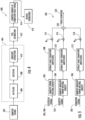
- FIG. 2 is a block diagram system 100 in accordance with an exemplary embodiment.
- the rotor assembly 110 is coupled to the generator 150 via the drivetrain 140.
- Electrical signals 204, 206 measured by the electrical sensors 170, 171, vibration signals 202 measured by the vibration signal measuring devices 180, and acoustic signals 210 measured by acoustic signal measuring device(s) 185 can be received by the control device 190 to generate analyzed electrical signal 212, analyzed vibration signal 214, and analyzed acoustic signal 216, respectively.
- the analyzed electrical signal 212, analyzed vibration signal 214, and analyzed acoustic signal 216 can be used to determine a fault condition 218.
- the fault condition 218 may be representative of one or more diagnostic parameters. It should be noted herein that the terms “fault condition” and “diagnostic parameter” may be used interchangeably.
- the fault condition 218 may be representative of various faults associated with the drivetrain 140, including but not limited to bearing faults, and gear faults of the drivetrain 140. For example, one or more gears 142, races 144, and bearings 146 or housings 148 associated with the drivetrain 140 can experience a fault.
- the faults of the drivetrain 140 may include but are not limited to high speed (HS) shaft gear fault, HS intermediate gear fault, planet gear fault, ring gear fault, sun gear fault, or the like.
- the fault condition 218 may be indicative of bearing fault of the drivetrain 140 such as HS shaft bearing fault, high speed intermediate shaft (HSIS) fault, low speed intermediate shaft (LSIS) fault, planet bearing fault, or the like.
- the faults of the drivetrain 140 can generate two types of vibrations, namely torsional and radial vibrations. These faults can further generate acoustic signals.
- Vibration signal measuring devices 180 effectively sense radial vibrations compared to sensing torsional vibrations.
- Acoustic signal measuring devices 185 sense acoustic signals, such as audible acoustic signals.
- Acoustic and vibration analysis are non-intrusive techniques for monitoring the condition of mechanical components within rotating machines. For example, the condition of a particular component may be determined by considering the frequency and magnitude of vibration signals 202 and acoustic signals 210 generated by the particular component.
- vibration and acoustic signal analysis involves analyzing frequency components of the vibration signal 202 and acoustic signal 210 measured from the drivetrain 140 and measuring the amplitude of the harmonic frequency components of the sideband of the vibration signal 202 and acoustic signal 210, and comparing with the amplitudes of adjacent harmonic frequencies.
- Electrical signal measuring devices 170, 171 are effective in monitoring electrical signals of the electrical machine having drivetrain faults due to torsional vibrations. Electrical signals 204, 206 are measured by the electrical signal measuring devices 170, 171 and are transmitted to the control device 190. As discussed herein, the electrical signal 204 is voltage signal and the electrical signal 206 is a current signal. Electrical signal analysis of the electrical signals 204, 206 can be performed by the control device 190 to generate one or more analyzed electrical signals 212. Based on the analyzed electrical signals 212, corresponding drivetrain faults can be determined. In an embodiment of the present invention, a voltage signature analysis can be performed by the control device 190 to determine the drivetrain faults.
- Vibration signal measuring device(s) 180 are effective in monitoring vibration signals generated by the drivetrain 140, generator 150, or other components of wind turbine 160.
- a plurality of vibration signal measuring devices 180 may be located at predetermined locations on a gearbox casing.
- the control device 190 can receives vibration signals 202 representative of the detected vibrations from the vibration signal measuring device 180.
- the control device 190 can analyze the vibration signals 202 to generate analyzed vibration signals 214.
- the control device 190 can analyze the vibration signals 202 by filtering, rectifying, extracting an envelope, and estimating a PSD for the vibration signals 202.
- Acoustic signal measuring device(s) 185 are effective in monitoring acoustic signals generated by the drivetrain 140.
- one or more acoustic signals can be positioned at predetermined locations within the wind turbine 160 to obtain acoustic signals associated with various components of the drivetrain 140.
- Acoustic signals 210 are measured by the acoustic signal measuring devices 185, and are transmitted to the control device 190.
- acoustic signal analysis of the acoustic signals 210 can be performed by the control device 190 to generate analyzed acoustic signals 216.
- the control device 190 can analyze the acoustic signals 210 by filtering, rectifying, extracting an envelope, and estimating a PSD for the acoustic signals 210.
- FIG. 3 a flow diagram of an example method (300) for determining a fault condition according to an example embodiment of the present disclosure is depicted.
- the method 300 can be implemented by a control device or control system, such as control device 190 depicted in FIGS. 1 and 2 , or a control device/system 810 depicted in FIG. 8 .
- FIG. 3 depicts steps performed in a particular order for purposes of illustration and discussion. Those of ordinary skill in the art, using the disclosures provided herein, will understand that various steps of any of the methods disclosed herein can be adapted, omitted, rearranged, or expanded in various ways without deviating from the scope of the present disclosure.
- the method (300) can include receiving an acoustic signal.
- one or more acoustic signal measuring devices 185 can be positioned proximate to a drivetrain 140 in a wind turbine 160.
- a plurality of acoustic signal measuring devices 185 such as an array of microphones, can be positioned proximate to the drivetrain 140.
- the one or more acoustic signal measuring devices 185 can be configured to measure an acoustic signal 210 during operation of the drivetrain 140, and can be configured to provide an acoustic signal 210 to a control device, such as a control device 190 and/or control device/system 810.
- the method (300) can include receiving a vibration signal.
- one or more vibration signal measuring devices 180 can be positioned proximate to a drivetrain 140, a generator 150, or other devices of the wind turbine 160.
- the one or more vibration signal measuring devices 180 can be configured to receive one or more vibration signals 202, such as stator vibrations, rotor vibrations, bearing vibrations, or other vibrations, and can be configured to provide a vibration signal 202 to a control device, such as a control device 190 and/or control device/system 810.
- the method (300) can include receiving an electrical signal.
- one or more electrical signal measuring devices 170, 171 can be coupled to a generator 150 and can be configured to measure a voltage, current, or other electrical signal from a generator 150.
- the one or more electrical signal measuring devices 170, 171 can be configured to receive one or more electrical signals 204, 206, and can be configured to provide an electrical signal 204, 206 to a control device, such as a control device 190 and/or control device/system 810.
- the method (300) can include analyzing the acoustic signal to determine an analyzed acoustic signal.
- a control device 190 and/or control device/system 810 can analyze the acoustic signal 210 to determine an analyzed acoustic signal 216.
- the method (300) can include analyzing the vibration signal to determine an analyzed vibration signal 214, and analyzing the electrical signal to determine an analyzed electrical signal 212, respectively.
- a control device 190 and/or control device/system 810 can analyze a vibration signal 202 to determine an analyzed vibration signal 214, and the control device 190 and/or control device/system 810 can analyze electrical signals 204, 206 to determine an analyzed electrical signal 212.
- the method (300) can include various methods of analyzing acoustic, vibration, and electrical signals. For example, at (314), the method (300) can include determining one or more signal signatures. Referring now to FIG. 4 , a flow diagram of a method (400) for determining a signal signature according to example aspects of the present disclosure is shown.
- the method (400) can be used to analyze one or more signals.
- acoustic signals 210 and vibration signals 202 can be analyzed for indications of fault via spectral analysis applied to the envelope of the signals.
- a signal can be sampled.
- a signal such as an acoustic signal 210 or a vibration signal 202 can be sampled at a sampling rate of 50 kHz.
- a sampled signal can be a 20 second signal sample.
- the spectrum of the envelope of each sampled signal can then be analyzed.
- the signal can first be provided to a high pass filter at (406).
- the signal can be high pass filtered to 1.2 kHz using an order-9 Butterworth high pass filter.
- the filtered signal can then be provided to a rectifier at (408).
- Other suitable high pass filters can similarly be used to filter the signal.
- the envelope of the signal can be extracted.
- the envelope can be extracted by applying the Hilbert transform to the absolute value of the signal.
- the envelope extraction can be performed by signal processing software. Other suitable envelope extraction methods can be used.
- the spectrum of the envelope can be extracted.
- a Welch PSD estimate using an FFT size of 131072 yielding a frequency resolution of 0.1953 Hz can be used.
- Other suitable spectral density estimation methods can be used.
- the spectra of the signal(s) can then be analyzed at or around one or more predicted fault frequencies to check whether or not there is a significant deviation between the signal(s) received from the signal measuring device(s) obtained from the wind turbine 160 and a baseline signal obtained from the wind turbine 160 during operation in which the wind turbine 160 was healthy.
- a baseline signal can be obtained in which the wind turbine is healthy (i.e., the component is not faulty), and the baseline signal can be analyzed in order to determine an analyzed baseline healthy signal.
- acoustic, vibration, and electrical signals measured in a healthy wind turbine 160 can all be used to determine respective baseline signals.
- the predicted fault frequencies can be determined based on different types of fault conditions. For example, for a faulty gear with two worn teeth, the main vibration frequencies are expected to be at multiples of the shaft rotation frequency. In addition these vibrations may be modulated by vibrations at multiples of the mesh frequency, defined as the shaft frequency multiplied by the number of teeth in the gear. For a faulty gear with all worn teeth, the main vibration frequencies are expected to be at multiples of the mesh frequency. In addition these vibrations may be modulated by vibrations at multiples of the shaft rotation frequency.
- f pred the predicted fault frequency
- N b the number of balls in the bearing
- f shaft the rotation frequency of the shaft
- Dp the pitch diameter
- Db the ball diameter
- ⁇ the contact angle.
- vibrations may also occur at multiples of the calculated frequency.
- other predicted fault frequencies can be determined for other components in wind turbine 160.
- integer values of -2, -1, 1, and 2 can be used to determine prominent predicted electrical signature frequencies.
- a maximum reading of the spectrum within an interval centered at the calculated frequency can be used for each analyzed signal.
- the interval width can be determined using the following formula: min max 2 % of ⁇ pred , 0.4 Hz , 4 Hz where f pred is the predicted frequency. Equation 4 can allow for a maximum offset of 1% of the calculated frequency or 2 Hz, whichever is smaller. Additionally, the maximum reading of the spectrum within an interval of width at least 0.4 Hz centered at the predicted fault frequency can be selected.
- the maximum reading of the spectra for each predicted fault frequency can be output as the signal signature(s) to be used for determining whether a fault condition exists in a component.
- the method (300) can include additional methods of analyzing acoustic, vibration, and electrical signals.
- the method (300) can include determining a fused signature.
- FIG. 5 a flow diagram of a method (500) for determining a fused signature according to example aspects of the present disclosure is shown.
- the method (500) can include analyzing the electrical signal, such as, for example, by computing the PSD of the electrical signal.
- an electrical signal 204, 206 can be provided to a control device 190 and/or control device/system 810.
- a PSD estimate can be performed on the electrical signal 204, 206, such as a Welch PSD estimation or other PSD estimation of a line-line voltage signal at the signature frequencies corresponding to a fault of interest.
- the method (500) can include analyzing the acoustic signal, such as, for example, by extracting the envelope of the acoustic signal and estimating a PSD of the acoustic signal.
- an acoustic signal 210 can be provided to a control device 190 and/or control device/system 810.
- an envelope for the signal can be extracted using a Hilbert transform, and a PSD can be estimated using the Welch PSD estimation technique as described herein. Additionally and/or alternatively, any other suitable envelope extraction or PSD estimation methods can be used.
- the PSD of the acoustic signal envelope at the acoustic signature frequencies corresponding to a fault of interest can be performed.
- the method (500) can include analyzing the vibration signal, such as, for example, by extracting the envelope of the vibration signal and estimating a PSD of the vibration signal.
- a vibration signal 202 can be provided to a control device 190 and/or control device/system 810.
- an envelope for the signal can be extracted using a Hilbert transform, and a PSD can be estimated using the Welch PSD estimation technique as described herein. Additionally and/or alternatively, any other suitable envelope extraction or PSD estimation methods can be used.
- the PSD of the vibration signal envelope at the acoustic signature frequencies corresponding to a fault of interest can be performed.
- the fault signature amplitudes for the electrical signal, acoustic signal, and vibration signal, respectively, can be extracted.
- different fault conditions may have different signature fault frequencies associated with each specific fault condition.
- the square root of the power spectrum can be computed, and can be referred to as the measurement at the signature frequency for the respective signal.
- the fault signature amplitude for the analyzed electrical signal 204, 206 can be combined with a corresponding weighting parameter w 1 .
- the fault signature amplitudes for an analyzed acoustic signal 210 and analyzed vibration signal 202 can similarly be combined with a respective corresponding weighting parameters w 2 and w 3 .
- the weighting parameters w 1 , w 2 , and w 3 can be calculated for each signature fault frequency for each of the respective signals.
- the weighted, analyzed electrical signal 204, 206, the weighted, analyzed acoustic signal 210, and the weighted, analyzed vibration signal 202 can be combined to create a fused signature 522.
- an example method (600) for identifying signature fault frequencies with a significant difference and determining corresponding significant signature fault frequency weighting parameters is depicted.
- the method (600) can be used to identify signature fault frequencies for which the fault signature amplitudes are extracted for creating a fused signature 522.
- a PSD at a signature fault frequency can be computed for an operational signal, such as an operational signal from a wind turbine 602 and a respective baseline signal, such as a baseline signal from a healthy wind turbine 604, respectively.
- the signature fault frequency can be a frequency associated with a particular fault condition, such as a predicted fault frequency as discussed herein.
- the operational signal from the wind turbine 602 can be, for example, an acoustic signal, a vibration signal, or an electrical signal, such as a signal from a wind turbine which is being examined for a fault, such as a vibration signal 202, an electrical signal 204, 206, or an acoustic signal 210.
- the respective baseline signal such as a baseline signal from a healthy turbine 604
- the PSD can be, for example, computed using a Welch PSD estimation or other PSD estimation as described herein.
- a one-tailed two-sample T-test between the measurements obtained under the operational and baseline conditions can be performed to determine whether there is a statistically significant increase in the measurements under the operational condition over those under baseline conditions.
- the method (600) can include determining whether the difference between the two signals is significant. For example, after computing the 1-sided two sample t-test statistic to evaluate the p-value for the null hypothesis that the PSD measurements from the two conditions have the same mean, the null hypothesis can be rejected if the p-value is below a threshold and it can be concluded that the increase in mean is significant.
- the method (600) can include discarding the signature fault frequencies which do not show a statistically significant increase in the measurements in the operational signal 602 relative to the baseline signal 604.
- the p-value cutoff required to indicate statistical significance can be user-specified.
- a p-value threshold of 0.01 and/or 0.05 can be used.
- the method (600) can include computing a weighting parameter corresponding to the significant signature fault frequency.
- the weighting parameter for each signal can be determined based at least in part on a mean value in a variance value of a difference between the operational signal 602 and the baseline signal 604 at one or more signature fault frequencies.
- the weighting parameter corresponding to the signature frequency can given by the ratio of the difference in means to the variance.
- the method (300) can include determining a fault condition for the component based at least in part on the analyzed signals.
- the analyzed signals can be, for example, one or more of an analyzed acoustic signal 216, an analyzed vibration signal 214, and an analyzed electrical signal 212.
- the method (300) can include comparing an analyzed signal to one or more thresholds.
- the one or more thresholds can be one or more thresholds at one or more signature fault frequencies.
- a signature fault frequency can be determined based at least in part on a baseline signal from a healthy wind turbine 160 and an operational signal from a wind turbine.
- the component such as a gear, bearing, race, or other component
- the component can be a component without a defect, and a signal measuring device can measure the signal.
- the component in the wind turbine being examined, can be a faulty, worn, or other component, such as a gear with a broken tooth.
- Both the baseline signal and the operational signal can be analyzed as described herein.
- the one or more thresholds can be determined based on a difference between the analyzed baseline signal and the analyzed operational signal at the one or more signature fault frequencies.
- the thresholds can be set at approximately the difference between the analyzed baseline signal and analyzed operational signal at the signature fault frequencies. Additionally and/or alternatively, the threshold can be another threshold.
- the one or more thresholds can correspond to various faulty components. For example, a first threshold at a first signature fault frequency can be used to determine whether a fault exists in a bearing, while a second threshold at a second signature fault frequency can be used to determine whether a fault exists in a gear. Additionally, in one or more embodiments, a plurality of thresholds can be used for diagnostic purposes, such as for measuring wear of components in order to provide maintenance on a wind turbine 160.
- the analyzed signal(s) can be compared to the one or more thresholds by, for example, comparing the magnitude of the envelope spectrum of the analyzed signal(s) at the one or more signature fault frequencies to the one or more thresholds. If, at (324), the analyzed signal exceeds the threshold, then at (326), a fault can be determined to exist. If, however, at (324) the analyzed signal does not exceed the threshold, then at (328), no fault exists.
- the one or more analyzed signals can include an analyzed acoustic signal and an analyzed vibration signal.
- the analyzed acoustic signal can be compared to a first threshold, and the analyzed vibration signal can be compared to a second threshold.
- a fault condition in a component can be determined to exist.
- the method (300) can include comparing the fused weighted signal to a threshold.
- a fused weighted signal can be determined by combining the weighted linear combination of all the measurements at all significant signature frequencies. If at (330), the fused weighted signal exceeds a threshold, then at (332), a fault can be determined to exist. If, however, (at 330), the fused weighted signal does not exceed the threshold, then at (328) no fault exists.
- a plurality of thresholds can be used to detect fault conditions based on a fused weighted signal or a plurality of analyzed signals.
- a detection system can be adapted to raise alarms at different severity levels of damage by setting appropriate thresholds. Further, a detection system can monitor progressive degradation of faults to predict failures and schedule maintenance in advance of a failure.
- the method can include performing a corrective action for the wind turbine based at least in part on the fault condition. For example, if a fault condition is determined to exist, a corrective action can include performing maintenance on the wind turbine to repair or replace the component of the wind turbine that is determined to be the cause of the fault. For example, a bearing, gear, or race can be repaired and/or replaced in order to correct the fault condition. Additionally and/or alternatively, the wind turbine can be scheduled for preventive maintenance at a future time period. For example, using one or more thresholds, a fault condition can indicate that a particular component will need to be repaired and/or replaced at a future time period. In some implementations, the corrective action can include scheduling maintenance at the future time period, such as during a routine maintenance period. In this way, the systems and methods according to example aspects of the present disclosure can allow for performing a corrective action on a wind turbine based at least in part on a fault condition.
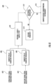
- FIG. 7 depicts an example graph of a simulation showing the probability of detecting a fault using example aspects of the present disclosure.
- FIG. 7 depicts a plot of receiver operating characteristics (ROCs) for a generator bearing at 800 RPM under a load of 5 kW and a p-value of 0.01.
- ROCs receiver operating characteristics
- a probability of detection is shown from 0.0 to 1.0, with a similar 0-100% probability.
- a vibration only signal (not shown due to overlapping signals), an acoustic only signal 702, an electrical signal 704, a fused signal of vibration, acoustic, and electrical signals 706, and a fused signal of electric and acoustic signals 708.
- the fused signals can provide an improved probability of detection at a reduced probability of false alarm over the individual signals 702 and 704.
- control device/system 810 can be used, for example, as a control device 190 as shown in FIGS. 1 and 2 .
- the control device/system 810 can include one or more processor(s) 812 and one or more memory device(s) 814.
- the processor(s) 812 and memory device(s) 814 can be distributed so that they are located at one more locales or with different devices.
- the processor(s) 812 and memory device(s) 814 can be configured to perform a variety of computer-implemented functions and/or instructions (e.g., performing the methods, steps, calculations and the like and storing relevant data as disclosed herein).
- the instructions when executed by the processor(s) 812 can cause the processor(s) 812 to perform operations according to example aspects of the present disclosure.
- the instructions when executed by the processor(s) 812 can cause the processor(s) 812 to implement the method of FIGS. 3-6 (300, 400, 500, 600) discussed herein.
- control device 810 can include a communication interface 816 to facilitate communications between the control device 810 and various components of a wind turbine, wind turbine system, wind farm, or power system, including power parameters, current parameters, voltage parameters, vibration parameters, acoustic parameters, or other parameters described herein.
- the communication interface 818 can include a sensor interface 818 (e.g., one or more analog-to-digital converters) to permit signals transmitted from one or more sensors 820, 822 to be converted into signals that can be understood and processed by the processor(s) 812.
- the sensors e.g. sensors 820, 822
- the communications interface 818 can be communicatively coupled to the communications interface 818 using any suitable means, such as a wired or wireless connection.
- the signals can be communicated using any suitable communications protocol.
- the sensors (820, 822) can be, for example, electrical signal measuring devices, such as voltage sensors, current sensors, or power sensors, vibration signal measuring devices, acoustic signal measuring devices, or any other sensor device or signal measuring device described herein.
- the processor(s) 812 can be configured to receive one or more signals from the sensors 820 and 822. For instance, in some embodiments, the processor(s) 812 can receive signals indicative of an acoustic signal from the sensor 820. In some embodiments, the processor(s) 812 can receive signals indicative of vibration from sensor 822.
- the term "processor” refers not only to integrated circuits referred to in the art as being included in a computer, but also refers to a control device, a microcontrol device, a microcomputer, a programmable logic control device (PLC), an application specific integrated circuit, and other programmable circuits.
- the memory device(s) 814 can generally include memory element(s) including, but not limited to, computer readable medium (e.g., random access memory (RAM)), computer readable non-volatile medium (e.g., a flash memory), a compact disc-read only memory (CD-ROM), a magneto-optical disk (MOD), a digital versatile disc (DVD) and/or other suitable memory elements.
- RAM random access memory
- CD-ROM compact disc-read only memory
- MOD magneto-optical disk
- DVD digital versatile disc
- Such memory device(s) 814 can generally be configured to store suitable computer-readable instructions that, when implemented by the processor(s) 812, configure the control device 810 to perform
Description
- The present disclosure relates generally to wind turbines, and more particularly to methods and systems for improved detection of faults in various components of drivetrains in wind turbines.
- Generally, a wind turbine includes a rotor that includes a rotatable hub assembly having multiple blades. The blades transform wind energy into a mechanical rotational torque that in turn drives a drivetrain coupled to an electrical generator. However, electrical generators, motors and the drive train in a wind turbine may generate torsional and radial vibrations due to presence of defective components such as bearings, gears, or the like. Conventionally, vibration analysis of components in a wind turbine can be performed to monitor operating conditions. For example, mechanical faults in wind turbines having a drive train may generate vibrations at the rotor rotating frequency. However, it has been found that vibration signals may not detect all types of faults associated with the various components of the drive train. Documents
US 2015/116131 A1 andUS 2015/292484 A1 relate to monitoring systems that diagnoses an abnormality of an apparatus provided in a wind turbine or a drive train health metric. DocumentUS 9576445 B2 - Aspects and advantages of the invention will be set forth in part in the following description.
- The present invention is directed to a method for determining a fault condition for a component of a drivetrain in a wind turbine according to
claim 1 and a control system according to claim 10. - One example aspect of the present disclosure is directed to a method for determining a fault condition for a component of a drivetrain in a wind turbine. The method can include receiving an acoustic signal from an acoustic signal measuring device. The method can further include receiving a vibration signal from a vibration signal measuring device. The method can further include analyzing the acoustic signal to determine an analyzed acoustic signal. The method can further include analyzing the vibration signal to determine an analyzed vibration signal. The method can further include determining a fault condition for the component based at least in part on the analyzed acoustic signal and analyzed vibration signal.
- Another example aspect of the present disclosure is directed to a control system. The control system can include an acoustic signal measurement device, an electrical signal measurement device, a vibration signal measurement device, and one or more processors and one or more memory devices configured to store instructions that when executed by the one or more processors cause the one or more processors to perform operations. The operations can include receiving first data indicative of an acoustic signal from the acoustic signal measurement device. The operations can further include receiving second data indicative of a vibration signal from the vibration signal measurement device. The operations can further include receiving third data indicative of an electrical signal from the electrical signal measurement device. The operations can further include processing the first data, second data, and third data to determine a first processed data, a second processed data, and a third processed data. The operations can further include determining a fault condition based at least in part on the first processed data, the second processed data, and the third processed data.
- Yet another example aspect of the present disclosure is directed to a wind turbine system. The wind turbine system can include a wind turbine, which can include a drivetrain. The drivetrain can include a plurality of components. The plurality of components can include a plurality of bearings, races, and gears. The wind turbine system can also include an acoustic signal measurement device, an electric signal measurement device, a vibration signal measurement device, and one or more processors and one or more memory devices configured to store instructions that when executed by the one or more processors cause the one or more processors to perform operations. The operations can include receiving first data indicative of an acoustic signal from the acoustic signal measurement device. The operations can further include receiving second data indicative of a vibration signal from the vibration signal measurement device. The operations can further include receiving third data indicative of an electrical signal from the electrical signal measurement device. The operations can further include processing the first data, second data, and third data to determine a first processed data, a second processed data, and a third processed data. The operations can further include determining a fault condition based at least in part on the first processed data, the second processed data, and the third processed data.
- Variations and modifications can be made to these example embodiments of the present disclosure.
- These and other features, aspects and advantages of the present invention will become better understood with reference to the following description and appended claims. The accompanying drawings, which are incorporated in and constitute a part of this specification, illustrate embodiments of the invention and, together with the description, serve to explain the principles of the invention.
- A full and enabling disclosure of the present invention, including the best mode thereof, directed to one of ordinary skill in the art, is set forth in the specification, which makes reference to the appended figures, in which:
-
FIG. 1 depicts a diagrammatic illustration of a system having a fault detection system according to example aspects of the present disclosure; -
FIG. 2 depicts a block diagram of a fault detection system according to example aspects of the present disclosure; -
FIG. 3 depicts a flow diagram of a method according to example aspects of the present disclosure; -
FIG. 4 depicts a flow diagram of a method according to example aspects of the present disclosure; -
FIG. 5 depicts a flow diagram of a method according to example aspects of the present disclosure; -
FIG. 6 depicts a flow diagram of a method according to example aspects of the present disclosure; -
FIG. 7 depicts an example graph of a simulation showing the probability of detecting a fault using example aspects of the present disclosure; -
FIG. 8 depicts an example control device according to example aspects of the present disclosure. - Reference now will be made in detail to embodiments of the invention, one or more examples of which are illustrated in the drawings. Each example is provided by way of explanation of the invention, not limitation of the invention. In fact, it will be apparent to those skilled in the art that various modifications and variations can be made in the present invention without departing from the scope of the invention which is defined by the appended claims.
- Generally, example aspects of the present disclosure are directed to systems and methods for detecting fault conditions. More particularly, a wind turbine system can include a drivetrain, which can include a plurality of components, such as gears, bearings, races, or other components. The wind turbine system can include a control system, such as a control system with one or more processors and one or more memory devices. The one or more processors can be configured to receive signals from one or more acoustic signal measuring devices, vibration signal measuring devices, and electrical signal measuring devices.
- A method for determining a fault condition can include receiving an acoustic signal from an acoustic signal measuring device and receiving a vibration signal from a vibration signal device. For example, a processor can be configured to receive data indicative of an acoustic signal and data indicative of a vibration signal. An acoustic signal measuring device can be, for example, a microphone or an array of microphones positioned proximate to a an examined mechanical device, such as a drivetrain in a wind turbine. Similarly, a vibration signal measuring device can be, for example, an accelerometer or other vibration signal measuring device positioned on a gearbox of the wind turbine.
- The method can also include analyzing the acoustic signal to determine an analyzed acoustic signal, and analyzing the vibration signal to determine an analyzed vibration signal. For example, the processor can be configured to perform the signal analysis. The method can also include determining a fault condition based at least in part on the analyzed acoustic signal and the analyzed vibration signal.
- For example, in an embodiment, analyzing the acoustic signal to determine an analyzed acoustic signal can include extracting an envelope of the signal and estimating a power spectral density ("PSD") for the acoustic signal. Similarly, an envelope can be extracted from the vibration signal, and a PSD for the envelope of the vibration signal can be estimated. Additionally, a fault condition can be determined based on the analyzed signals. For example, the PSD of the envelope of the the analyzed the envelope of acoustic signal can be compared to a first threshold at a signature fault frequency, and the PSD of the envelope of the analyzed vibration signal can be compared to a second threshold at the signature fault frequency. The signature fault frequency can be, for example, a frequency associated with a specific type of fault, such as a chipped tooth on a gear, a defective ball bearing, or a worn component. In one or more embodiments, the signature fault frequencies can be one or more predicted fault frequencies, wherein the predicted fault frequency is a frequency where an analyzed signal is expected to exhibit a particular characteristic, such as an elevated energy level due to the nature of the fault. For example, a predicted fault frequency can be calculated based on a shaft rotation frequency or a mesh frequency for a gear. In an embodiment, a fault condition can be determined to exist when the analyzed acoustic signal exceeds the first threshold, and the analyzed vibration signal exceeds the second threshold.
- The method can further include receiving an electrical signal from an electrical signal measuring device. For example, a voltage sensor or a current sensor can be configured to measure an electrical signal, such as an electrical signal from a generator coupled to a drivetrain in a wind turbine. The method can further include analyzing the electrical signal to determine an analyzed electrical signal. In an embodiment, a fault condition can additionally be based at least in part on the analyzed electrical signal. For example, an acoustic signal, a vibration signal, and an electrical signal can all be analyzed to determine respective analyzed signals. In an embodiment, analyzing each of the acoustic signal, the vibration signal, and the electrical signal can include estimating a PSD for each signal. For example, an envelope can be extracted and/or a PSD estimation can be performed, such as a Welch PSD estimation.
- The method can further include extracting one or more fault signature amplitudes for each of the acoustic signal, the vibration signal, and the electrical signal. For example, the one or more fault signature amplitudes can be extracted based at least in part on each respective signal and a respective baseline signal. For example, a baseline signal can be obtained from a device in which no fault condition exists. For example, an acoustic signal can be obtained for a drivetrain of a healthy wind turbine, or an electrical signal can be obtained from a generator coupled to a drivetrain of a wind turbine. The baseline signal can similarly be analyzed, such as by extracting an envelope and estimating a PSD of the signal at one or more signature fault frequencies. The signature fault frequencies can be, for example, frequencies associated with a particular fault, such as one or more predicted fault frequencies. In an embodiment, significant fault signature amplitudes can be extracted at the signature fault frequencies, while insignificant fault signature amplitudes can be discarded. In this way, fault signature amplitudes in which a significant difference between a signal and a respective baseline signal can be used for further analysis.
- In an embodiment, analyzing each of the acoustic signal, the vibration signal, and the electrical signal can include determining a weighting parameter for each respective signal. For example, a weighting parameter can be determined for each respective signal, and can be based on a mean value and a variance value of a difference between the respective signal and a respective baseline signal at one or more signature fault frequencies. Further, a fault condition can be determined based at least in part on the weighting parameter for each respective signal. For example, each respective signal can be combined with a respective weighting parameter for each signature fault frequency extracted from the signal. A fused signal can be created by combining the weighted signature fault frequency amplitudes for each signal at the signature fault frequencies. In an embodiment, a fault condition can be determined to exist when the fused signal exceeds a threshold. For example, a threshold can be set based at least in part on a particular type of fault condition, such as a gear with a chipped tooth, or a defective ball bearing. The fused signal can be compared to the threshold, and when the fused signal exceeds the threshold, a fault condition can be determined to exist. In an embodiment, a plurality of thresholds can be used, such as thresholds associated with various wear levels for specific components.
- In this way, the systems and methods according to example aspects of the present disclosure can have a technical effect of allowing for the detection of fault conditions, such as fault conditions in a component of a drivetrain in a wind turbine based on acoustic, vibration, and/or electrical signals. Further, the systems and methods according to example aspects of the present disclosure can allow for fusing of a plurality of signals, which can allow for an increased efficiency for the processing of acoustic, vibration, and electrical signals. Moreover, the systems and methods according to example aspects of the present disclosure can allow for diagnosing and predicting component failures, which can enable preventive maintenance to be performed before a fault condition occurs, thereby allowing for a reduction in the necessary downtime for unscheduled maintenance.
- With reference now to the FIGS., example aspects of the present disclosure will now be discussed in detail.
FIG. 1 is a diagrammatic illustration of asystem 100 in accordance with example aspects of the present disclosure. Thesystem 100 includes awind turbine 160 having at least oneelectrical device 150 and amechanical device 140. Thesystem 100 further includes at least one electrical signal measuring device170, 171 to measure electrical signals, at least one vibrationsignal measuring device 180 to measure vibrations from thewind turbine 160, and at least one acousticsignal measuring device 185 to measure acoustic signals from thewind turbine 160. The number of electrical signal, vibration signal, and acoustic signal measuring devices may vary depending on the application. In one embodiment, only one electrical signal, one vibration signal, and one acoustic signal measuring device may be included in asystem 100. Additionally and/or alternatively, a plurality of each type of signal measuring device can be included in asystem 100. For example, an array of acousticsignal measuring devices 185, such as an array of microphones, can be positioned along the axis of adrivetrain 140 in awind turbine 160. - The
system 100 can further include acontrol device 190 for receiving electrical signals, vibration signals, and acoustic signals measured by the electrical signal measuring device(s) 170, 171, the vibration signal measuring device(s) 180, and the acoustic signal measuring device(s) 185. Thewind turbine 160 also includes arotor assembly 110, amain bearing 120, and amain shaft 130. In the illustrated embodiment, theelectrical device 150 is a generator for generatingoutput power 208, and themechanical device 140 is a drivetrain. It should be noted herein that theelectrical device 150 may be referred to as a motor and themechanical device 140 may be referred to as a gearbox/drivetrain interchangeably. In other embodiments, other types of electrical and mechanical devices are envisioned. - In the illustrated embodiment, the electrical
signal measuring device 170 is a current sensor for sensing current and the other electricalsignal measuring device 171 is a voltage sensor for sensing voltage of thegenerator 150. The electricalsignal measuring devices current sensor 170 measures current flowing through one or more phases of thegenerator 150. Similarly, thevoltage sensor 171 may measure voltage across one or more phases of thegenerator 150. While certain embodiments of the present technology may be discussed with respect to a multi-phase generator, it should be noted herein that in other embodiments of the present technology, other types of wind turbines may be envisioned. The vibrationsignal measuring device 180 can be used to detect vibrations of at least one of thegenerator 150, thedrivetrain 140, and other devices of thewind turbine 160. The vibrations may include at least one of stator vibrations, rotor vibrations, and bearing vibrations. The vibrationsignal measuring device 180 may be an accelerometer, a displacement transducer or a velocity transducer. The acoustic signal measuring device(s) 185 can be used to sense acoustic signals associated with operation of thewind turbine 160. The acoustic signal measuring device(s) 185 may also be referred to as acoustic sensors or microphones. For example, the acoustic signal measuring device(s) can be microphones configured to sense acoustic signals from thewind turbine 160, such as acoustic signals generated by operation of thedrivetrain 140. Other types of vibration signal, electrical signal, and acoustic signal measuring devices may also be envisioned within the scope of the present technology. - The
control device 190 can receive signals from the vibrationsignal measuring device 180, the electricalsignal measuring devices control device 190 may be a general purpose computer, a Digital Signal Processor (DSP), or a control device/system 810 as discussed with reference toFIG. 8 . Thecontrol device 190 may include an input device (not shown) such as a keyboard, a mouse, and a controller for receiving additional information from a user to configure thecontrol device 190 to perform various computational operations associated with the present invention. Thecontrol device 190 may include amemory 200 which may be a random access memory (RAM), read only memory (ROM), or any other form of computer readable memory accessible by thecontrol device 190. Thememory 200 may be encoded with a program to instruct thecontrol device 190 to enable a sequence of steps to determine a fault of thedrivetrain 140. Thecontrol device 190 may also be suitably configured to monitor and detect fault conditions of various components, for example, the bearing faults of thedrivetrain 140, within thewind turbine 160. -
FIG. 2 is ablock diagram system 100 in accordance with an exemplary embodiment. As discussed with reference toFIG. 1 , therotor assembly 110 is coupled to thegenerator 150 via thedrivetrain 140.Electrical signals electrical sensors signal measuring devices 180, andacoustic signals 210 measured by acoustic signal measuring device(s) 185 can be received by thecontrol device 190 to generate analyzedelectrical signal 212, analyzedvibration signal 214, and analyzedacoustic signal 216, respectively. The analyzedelectrical signal 212, analyzedvibration signal 214, and analyzedacoustic signal 216 can be used to determine afault condition 218. Thefault condition 218 may be representative of one or more diagnostic parameters. It should be noted herein that the terms "fault condition" and "diagnostic parameter" may be used interchangeably. In the illustrated embodiment, thefault condition 218 may be representative of various faults associated with thedrivetrain 140, including but not limited to bearing faults, and gear faults of thedrivetrain 140. For example, one or more gears 142, races 144, and bearings 146 orhousings 148 associated with thedrivetrain 140 can experience a fault. In certain embodiments, the faults of thedrivetrain 140 may include but are not limited to high speed (HS) shaft gear fault, HS intermediate gear fault, planet gear fault, ring gear fault, sun gear fault, or the like. In some embodiments, additionally, thefault condition 218 may be indicative of bearing fault of thedrivetrain 140 such as HS shaft bearing fault, high speed intermediate shaft (HSIS) fault, low speed intermediate shaft (LSIS) fault, planet bearing fault, or the like. - The faults of the
drivetrain 140 can generate two types of vibrations, namely torsional and radial vibrations. These faults can further generate acoustic signals. Vibrationsignal measuring devices 180 effectively sense radial vibrations compared to sensing torsional vibrations. Acousticsignal measuring devices 185 sense acoustic signals, such as audible acoustic signals. Acoustic and vibration analysis are non-intrusive techniques for monitoring the condition of mechanical components within rotating machines. For example, the condition of a particular component may be determined by considering the frequency and magnitude ofvibration signals 202 andacoustic signals 210 generated by the particular component. Generally, components in good condition, for example, gears with complete sets of teeth, generate smaller amplitude vibrations and acoustic signals than components in poor condition, for example, gears with chipped or missing teeth. The frequencies of vibrations and acoustic signals generated by the gears are unique to the gear design and shaft rotation speed. One technique of vibration and acoustic signal analysis involves analyzing frequency components of thevibration signal 202 andacoustic signal 210 measured from thedrivetrain 140 and measuring the amplitude of the harmonic frequency components of the sideband of thevibration signal 202 andacoustic signal 210, and comparing with the amplitudes of adjacent harmonic frequencies. - Electrical
signal measuring devices Electrical signals signal measuring devices control device 190. As discussed herein, theelectrical signal 204 is voltage signal and theelectrical signal 206 is a current signal. Electrical signal analysis of theelectrical signals control device 190 to generate one or more analyzedelectrical signals 212. Based on the analyzedelectrical signals 212, corresponding drivetrain faults can be determined. In an embodiment of the present invention, a voltage signature analysis can be performed by thecontrol device 190 to determine the drivetrain faults. - Vibration signal measuring device(s) 180 are effective in monitoring vibration signals generated by the
drivetrain 140,generator 150, or other components ofwind turbine 160. For example, a plurality of vibrationsignal measuring devices 180 may be located at predetermined locations on a gearbox casing. Thecontrol device 190 can receives vibration signals 202 representative of the detected vibrations from the vibrationsignal measuring device 180. Thecontrol device 190 can analyze the vibration signals 202 to generate analyzed vibration signals 214. In one embodiment, thecontrol device 190 can analyze the vibration signals 202 by filtering, rectifying, extracting an envelope, and estimating a PSD for the vibration signals 202. - Acoustic signal measuring device(s) 185 are effective in monitoring acoustic signals generated by the
drivetrain 140. For example, one or more acoustic signals can be positioned at predetermined locations within thewind turbine 160 to obtain acoustic signals associated with various components of thedrivetrain 140.Acoustic signals 210 are measured by the acousticsignal measuring devices 185, and are transmitted to thecontrol device 190. As discussed herein acoustic signal analysis of theacoustic signals 210 can be performed by thecontrol device 190 to generate analyzedacoustic signals 216. In one embodiment, thecontrol device 190 can analyze theacoustic signals 210 by filtering, rectifying, extracting an envelope, and estimating a PSD for the acoustic signals 210. - Referring now to
FIG. 3 , a flow diagram of an example method (300) for determining a fault condition according to an example embodiment of the present disclosure is depicted. Themethod 300 can be implemented by a control device or control system, such ascontrol device 190 depicted inFIGS. 1 and2 , or a control device/system 810 depicted inFIG. 8 . In addition,FIG. 3 depicts steps performed in a particular order for purposes of illustration and discussion. Those of ordinary skill in the art, using the disclosures provided herein, will understand that various steps of any of the methods disclosed herein can be adapted, omitted, rearranged, or expanded in various ways without deviating from the scope of the present disclosure. - At (302), the method (300) can include receiving an acoustic signal. For example, one or more acoustic
signal measuring devices 185 can be positioned proximate to adrivetrain 140 in awind turbine 160. In an embodiment, a plurality of acousticsignal measuring devices 185, such as an array of microphones, can be positioned proximate to thedrivetrain 140. The one or more acousticsignal measuring devices 185 can be configured to measure anacoustic signal 210 during operation of thedrivetrain 140, and can be configured to provide anacoustic signal 210 to a control device, such as acontrol device 190 and/or control device/system 810. - At (304), the method (300) can include receiving a vibration signal. For example, one or more vibration
signal measuring devices 180 can be positioned proximate to adrivetrain 140, agenerator 150, or other devices of thewind turbine 160. The one or more vibrationsignal measuring devices 180 can be configured to receive one or more vibration signals 202, such as stator vibrations, rotor vibrations, bearing vibrations, or other vibrations, and can be configured to provide avibration signal 202 to a control device, such as acontrol device 190 and/or control device/system 810. - At (306), the method (300) can include receiving an electrical signal. For example, one or more electrical
signal measuring devices generator 150 and can be configured to measure a voltage, current, or other electrical signal from agenerator 150. The one or more electricalsignal measuring devices electrical signals electrical signal control device 190 and/or control device/system 810. - At (308), the method (300) can include analyzing the acoustic signal to determine an analyzed acoustic signal. For example, a
control device 190 and/or control device/system 810 can analyze theacoustic signal 210 to determine an analyzedacoustic signal 216. Similarly, at (310) and (312), the method (300) can include analyzing the vibration signal to determine an analyzedvibration signal 214, and analyzing the electrical signal to determine an analyzedelectrical signal 212, respectively. For example, acontrol device 190 and/or control device/system 810 can analyze avibration signal 202 to determine an analyzedvibration signal 214, and thecontrol device 190 and/or control device/system 810 can analyzeelectrical signals electrical signal 212. - The method (300) can include various methods of analyzing acoustic, vibration, and electrical signals. For example, at (314), the method (300) can include determining one or more signal signatures. Referring now to
FIG. 4 , a flow diagram of a method (400) for determining a signal signature according to example aspects of the present disclosure is shown. The method (400) can be used to analyze one or more signals. In an embodiment,acoustic signals 210 andvibration signals 202 can be analyzed for indications of fault via spectral analysis applied to the envelope of the signals. - At (402), a signal can be sampled. For example, in an embodiment, a signal, such as an
acoustic signal 210 or avibration signal 202 can be sampled at a sampling rate of 50 kHz. For example, a sampled signal can be a 20 second signal sample. At (404), the spectrum of the envelope of each sampled signal can then be analyzed. - For example, the signal can first be provided to a high pass filter at (406). In an embodiment, the signal can be high pass filtered to 1.2 kHz using an order-9 Butterworth high pass filter. The filtered signal can then be provided to a rectifier at (408). Other suitable high pass filters can similarly be used to filter the signal.
- At (410) the envelope of the signal can be extracted. For example, in an embodiment, the envelope can be extracted by applying the Hilbert transform to the absolute value of the signal. The envelope can be extracted using the following formula:

where senv (t) is the envelope, s(t) is the absolute value of the filtered signal, and ŝ(t) is the Hilbert transform of s(t). The envelope extraction can be performed by signal processing software. Other suitable envelope extraction methods can be used. - At (412), the spectrum of the envelope can be extracted. In an embodiment, a Welch PSD estimate using an FFT size of 131072 yielding a frequency resolution of 0.1953 Hz can be used. Other suitable spectral density estimation methods can be used.
- At (414), the spectra of the signal(s) can then be analyzed at or around one or more predicted fault frequencies to check whether or not there is a significant deviation between the signal(s) received from the signal measuring device(s) obtained from the
wind turbine 160 and a baseline signal obtained from thewind turbine 160 during operation in which thewind turbine 160 was healthy. - For example, a baseline signal can be obtained in which the wind turbine is healthy (i.e., the component is not faulty), and the baseline signal can be analyzed in order to determine an analyzed baseline healthy signal. For example, acoustic, vibration, and electrical signals measured in a
healthy wind turbine 160 can all be used to determine respective baseline signals. - The predicted fault frequencies can be determined based on different types of fault conditions. For example, for a faulty gear with two worn teeth, the main vibration frequencies are expected to be at multiples of the shaft rotation frequency. In addition these vibrations may be modulated by vibrations at multiples of the mesh frequency, defined as the shaft frequency multiplied by the number of teeth in the gear. For a faulty gear with all worn teeth, the main vibration frequencies are expected to be at multiples of the mesh frequency. In addition these vibrations may be modulated by vibrations at multiples of the shaft rotation frequency. For a fault on the generator bearing's inner race, the vibration frequency in this case is given by the following equation:

wind turbine 160. - For electrical signals, these vibrations can be further modulated by the fundamental electrical frequency, and hence the signature frequencies can be further shifted from the predicted mechanical frequencies by integer multiples of the fundamental electrical frequency. Thus, the predicted electrical signature frequencies can be given by the following equation:

- Due to inaccuracies in the part dimensions and the speed and sampling rate measurements, however, the predicted fault frequencies may not precisely correspond to the observed frequencies. In an embodiment, in order to account for such discrepancies, a maximum reading of the spectrum within an interval centered at the calculated frequency can be used for each analyzed signal. For example, in an embodiment, the interval width can be determined using the following formula:

- At (416), in an embodiment, the maximum reading of the spectra for each predicted fault frequency can be output as the signal signature(s) to be used for determining whether a fault condition exists in a component.
- Referring back to
FIG. 3 , the method (300) can include additional methods of analyzing acoustic, vibration, and electrical signals. For example, at (316), the method (300) can include determining a fused signature. Referring now toFIG. 5 , a flow diagram of a method (500) for determining a fused signature according to example aspects of the present disclosure is shown. - At (502), the method (500) can include analyzing the electrical signal, such as, for example, by computing the PSD of the electrical signal. For example, an
electrical signal control device 190 and/or control device/system 810. A PSD estimate can be performed on theelectrical signal - At (504), the method (500) can include analyzing the acoustic signal, such as, for example, by extracting the envelope of the acoustic signal and estimating a PSD of the acoustic signal. For example, an
acoustic signal 210 can be provided to acontrol device 190 and/or control device/system 810. In an embodiment, an envelope for the signal can be extracted using a Hilbert transform, and a PSD can be estimated using the Welch PSD estimation technique as described herein. Additionally and/or alternatively, any other suitable envelope extraction or PSD estimation methods can be used. The PSD of the acoustic signal envelope at the acoustic signature frequencies corresponding to a fault of interest can be performed. - At (506), the method (500) can include analyzing the vibration signal, such as, for example, by extracting the envelope of the vibration signal and estimating a PSD of the vibration signal. For example, a
vibration signal 202 can be provided to acontrol device 190 and/or control device/system 810. In an embodiment, an envelope for the signal can be extracted using a Hilbert transform, and a PSD can be estimated using the Welch PSD estimation technique as described herein. Additionally and/or alternatively, any other suitable envelope extraction or PSD estimation methods can be used. The PSD of the vibration signal envelope at the acoustic signature frequencies corresponding to a fault of interest can be performed. - At (508), (510), and (512), the fault signature amplitudes for the electrical signal, acoustic signal, and vibration signal, respectively, can be extracted. For example, different fault conditions may have different signature fault frequencies associated with each specific fault condition. For each signature fault frequency and each respective signal, the square root of the power spectrum can be computed, and can be referred to as the measurement at the signature frequency for the respective signal.
- At (514) the fault signature amplitude for the analyzed
electrical signal acoustic signal 210 and analyzedvibration signal 202 can similarly be combined with a respective corresponding weighting parameters w2 and w 3. The weighting parameters w 1, w 2, and w 3 can be calculated for each signature fault frequency for each of the respective signals. At (520), the weighted, analyzedelectrical signal acoustic signal 210, and the weighted, analyzedvibration signal 202 can be combined to create a fusedsignature 522. - Referring now to
FIG. 6 , an example method (600) for identifying signature fault frequencies with a significant difference and determining corresponding significant signature fault frequency weighting parameters is depicted. The method (600) can be used to identify signature fault frequencies for which the fault signature amplitudes are extracted for creating a fusedsignature 522. - As there are multiple candidate frequencies at which vibration signatures can appear, such as predicted fault frequencies as described herein, it may be important to select the significant fault frequencies which show a significant increase in readings under the faulty condition relative to that under the healthy conditions.
- As shown, at (606) and (608) a PSD at a signature fault frequency can be computed for an operational signal, such as an operational signal from a
wind turbine 602 and a respective baseline signal, such as a baseline signal from ahealthy wind turbine 604, respectively. The signature fault frequency can be a frequency associated with a particular fault condition, such as a predicted fault frequency as discussed herein. The operational signal from thewind turbine 602 can be, for example, an acoustic signal, a vibration signal, or an electrical signal, such as a signal from a wind turbine which is being examined for a fault, such as avibration signal 202, anelectrical signal acoustic signal 210. The respective baseline signal, such as a baseline signal from ahealthy turbine 604, can be, for example, a corresponding acoustic, vibration, or electrical signal previously obtained from a wind turbine known to not be experiencing a fault condition, such as an acoustic, vibration, or electrical signal obtained from ahealthy wind turbine 160 during operation of thewind turbine 160. The PSD can be, for example, computed using a Welch PSD estimation or other PSD estimation as described herein. - At (610), at each signature frequency and for each signal, a one-tailed two-sample T-test between the measurements obtained under the operational and baseline conditions can be performed to determine whether there is a statistically significant increase in the measurements under the operational condition over those under baseline conditions.
- At (612), the method (600) can include determining whether the difference between the two signals is significant. For example, after computing the 1-sided two sample t-test statistic to evaluate the p-value for the null hypothesis that the PSD measurements from the two conditions have the same mean, the null hypothesis can be rejected if the p-value is below a threshold and it can be concluded that the increase in mean is significant.
- At (614), the method (600) can include discarding the signature fault frequencies which do not show a statistically significant increase in the measurements in the
operational signal 602 relative to thebaseline signal 604. In an embodiment, the p-value cutoff required to indicate statistical significance can be user-specified. In an embodiment, a p-value threshold of 0.01 and/or 0.05 can be used. - At (616), the method (600) can include computing a weighting parameter corresponding to the significant signature fault frequency. In an embodiment, the weighting parameter for each signal can be determined based at least in part on a mean value in a variance value of a difference between the
operational signal 602 and thebaseline signal 604 at one or more signature fault frequencies. - For example, in order to determine a weighting parameter, the difference in means between the operational and baseline signals can be computed and the common variance of the signals can be computed, and a weighting parameter can be computed using the following equation:

- Referring back to
FIG. 3 , at (318), the method (300) can include determining a fault condition for the component based at least in part on the analyzed signals. The analyzed signals can be, for example, one or more of an analyzedacoustic signal 216, an analyzedvibration signal 214, and an analyzedelectrical signal 212. For example, at (320), the method (300) can include comparing an analyzed signal to one or more thresholds. The one or more thresholds can be one or more thresholds at one or more signature fault frequencies. For example, a signature fault frequency can be determined based at least in part on a baseline signal from ahealthy wind turbine 160 and an operational signal from a wind turbine. For example, in the healthy turbine, the component, such as a gear, bearing, race, or other component, can be a component without a defect, and a signal measuring device can measure the signal. Similarly, in the wind turbine being examined, the component can be a faulty, worn, or other component, such as a gear with a broken tooth. Both the baseline signal and the operational signal can be analyzed as described herein. In some embodiments, the one or more thresholds can be determined based on a difference between the analyzed baseline signal and the analyzed operational signal at the one or more signature fault frequencies. For example, the thresholds can be set at approximately the difference between the analyzed baseline signal and analyzed operational signal at the signature fault frequencies. Additionally and/or alternatively, the threshold can be another threshold. The one or more thresholds can correspond to various faulty components. For example, a first threshold at a first signature fault frequency can be used to determine whether a fault exists in a bearing, while a second threshold at a second signature fault frequency can be used to determine whether a fault exists in a gear. Additionally, in one or more embodiments, a plurality of thresholds can be used for diagnostic purposes, such as for measuring wear of components in order to provide maintenance on awind turbine 160. - The analyzed signal(s) can be compared to the one or more thresholds by, for example, comparing the magnitude of the envelope spectrum of the analyzed signal(s) at the one or more signature fault frequencies to the one or more thresholds. If, at (324), the analyzed signal exceeds the threshold, then at (326), a fault can be determined to exist. If, however, at (324) the analyzed signal does not exceed the threshold, then at (328), no fault exists.
- In an embodiment, the one or more analyzed signals can include an analyzed acoustic signal and an analyzed vibration signal. The analyzed acoustic signal can be compared to a first threshold, and the analyzed vibration signal can be compared to a second threshold. When the analyzed acoustic signal exceeds the first threshold and the analyzed vibration signal exceeds the second threshold, a fault condition in a component can be determined to exist.
- Similarly, at (322), the method (300) can include comparing the fused weighted signal to a threshold. For example, a fused weighted signal can be determined by combining the weighted linear combination of all the measurements at all significant signature frequencies. If at (330), the fused weighted signal exceeds a threshold, then at (332), a fault can be determined to exist. If, however, (at 330), the fused weighted signal does not exceed the threshold, then at (328) no fault exists.
- A plurality of thresholds can be used to detect fault conditions based on a fused weighted signal or a plurality of analyzed signals. For example, a detection system can be adapted to raise alarms at different severity levels of damage by setting appropriate thresholds. Further, a detection system can monitor progressive degradation of faults to predict failures and schedule maintenance in advance of a failure.
- At (334), the method can include performing a corrective action for the wind turbine based at least in part on the fault condition. For example, if a fault condition is determined to exist, a corrective action can include performing maintenance on the wind turbine to repair or replace the component of the wind turbine that is determined to be the cause of the fault. For example, a bearing, gear, or race can be repaired and/or replaced in order to correct the fault condition. Additionally and/or alternatively, the wind turbine can be scheduled for preventive maintenance at a future time period. For example, using one or more thresholds, a fault condition can indicate that a particular component will need to be repaired and/or replaced at a future time period. In some implementations, the corrective action can include scheduling maintenance at the future time period, such as during a routine maintenance period. In this way, the systems and methods according to example aspects of the present disclosure can allow for performing a corrective action on a wind turbine based at least in part on a fault condition.
-
FIG. 7 depicts an example graph of a simulation showing the probability of detecting a fault using example aspects of the present disclosure.FIG. 7 depicts a plot of receiver operating characteristics (ROCs) for a generator bearing at 800 RPM under a load of 5 kW and a p-value of 0.01. On the x-axis, a probability of a false alarm is shown from 0.0 to 1.0, with 0.0 corresponding to a 0% probability and 1.0 corresponding to a 100% probability. On the y-axis, a probability of detection is shown from 0.0 to 1.0, with a similar 0-100% probability. - As shown, five signals and signal combinations are graphed a vibration only signal (not shown due to overlapping signals), an acoustic only signal 702, an
electrical signal 704, a fused signal of vibration, acoustic, andelectrical signals 706, and a fused signal of electric andacoustic signals 708. As shown bycurves individual signals - Referring now to
FIG. 8 , an example control device/system 810 according to example embodiments of the present disclosure is depicted. The control device/system 810 can be used, for example, as acontrol device 190 as shown inFIGS. 1 and2 . In some embodiments, the control device/system 810 can include one or more processor(s) 812 and one or more memory device(s) 814. The processor(s) 812 and memory device(s) 814 can be distributed so that they are located at one more locales or with different devices. - The processor(s) 812 and memory device(s) 814 can be configured to perform a variety of computer-implemented functions and/or instructions (e.g., performing the methods, steps, calculations and the like and storing relevant data as disclosed herein). The instructions when executed by the processor(s) 812 can cause the processor(s) 812 to perform operations according to example aspects of the present disclosure. For instance, the instructions when executed by the processor(s) 812 can cause the processor(s) 812 to implement the method of
FIGS. 3-6 (300, 400, 500, 600) discussed herein. - Additionally, the
control device 810 can include acommunication interface 816 to facilitate communications between thecontrol device 810 and various components of a wind turbine, wind turbine system, wind farm, or power system, including power parameters, current parameters, voltage parameters, vibration parameters, acoustic parameters, or other parameters described herein. Further, thecommunication interface 818 can include a sensor interface 818 (e.g., one or more analog-to-digital converters) to permit signals transmitted from one ormore sensors e.g. sensors 820, 822) can be communicatively coupled to thecommunications interface 818 using any suitable means, such as a wired or wireless connection. The signals can be communicated using any suitable communications protocol. The sensors (820, 822) can be, for example, electrical signal measuring devices, such as voltage sensors, current sensors, or power sensors, vibration signal measuring devices, acoustic signal measuring devices, or any other sensor device or signal measuring device described herein. - As such, the processor(s) 812 can be configured to receive one or more signals from the
sensors sensor 820. In some embodiments, the processor(s) 812 can receive signals indicative of vibration fromsensor 822. - As used herein, the term "processor" refers not only to integrated circuits referred to in the art as being included in a computer, but also refers to a control device, a microcontrol device, a microcomputer, a programmable logic control device (PLC), an application specific integrated circuit, and other programmable circuits. Additionally, the memory device(s) 814 can generally include memory element(s) including, but not limited to, computer readable medium (e.g., random access memory (RAM)), computer readable non-volatile medium (e.g., a flash memory), a compact disc-read only memory (CD-ROM), a magneto-optical disk (MOD), a digital versatile disc (DVD) and/or other suitable memory elements. Such memory device(s) 814 can generally be configured to store suitable computer-readable instructions that, when implemented by the processor(s) 812, configure the
control device 810 to perform the various functions as described herein. - The technology discussed herein makes reference to computer-based systems and actions taken by and information sent to and from computer-based systems. One of ordinary skill in the art will recognize that the inherent flexibility of computer-based systems allows for a great variety of possible configurations, combinations, and divisions of tasks and functionality between and among components. For instance, processes discussed herein can be implemented using a single computing device or multiple computing devices working in combination. Databases, memory, instructions, and applications can be implemented on a single system or distributed across multiple systems. Distributed components can operate sequentially or in parallel.
- Although specific features of various embodiments may be shown in some drawings and not in others, this is for convenience only. In accordance with the principles of the present disclosure, any feature of a drawing may be referenced and/or claimed in combination with any feature of any other drawing.
- The scope of protection is determined by the appended claims.
Claims (15)
- A method for determining a fault condition (218) for a component of a drivetrain (140) in a wind turbine (160), comprising:measuring an audible acoustic signal using an acoustic signal measuring device (185) positioned proximate to the drive train (140) of the wind turbine;measuring a vibration signal (202) using a vibration signal measuring device (180) configured to measure vibrations of the drivetrain (140), a generator, or other device of the wind turbine;transmitting the acoustic signal and the vibration signal to a control device (190);receiving the acoustic signal (210) from the acoustic signal measuring device (185);receiving the vibration signal (202) from the vibration signal measuring device (180);analyzing the acoustic signal (210) to determine an analyzed acoustic signal (216) comprising extracting an envelope and estimating a power spectral density for the acoustic signal (210);analyzing the vibration signal (202) to determine an analyzed vibration signal (214) comprising extracting an envelope and estimating a power spectral density for the vibration signal (202);determining a fault condition (218) for the component based at least in part on the analyzed acoustic signal (216) and analyzed vibration signal (214); andperforming a corrective action for the wind turbine (160) based at least in part on the fault condition (218).
- The method of claim 1, wherein determining a fault condition (218) comprises:comparing the analyzed acoustic signal (216) to a first threshold at a signature fault frequency; andcomparing the analyzed vibration signal (214) to a second threshold at the signature fault frequency.
- The method of claim 2, wherein a fault condition (218) in the component is determined to exist when the analyzed acoustic signal (216) exceeds the first threshold at the signature fault frequency and the analyzed vibration signal (214) exceeds the second threshold at the signature fault frequency.
- The method of any of the preceding claims, further comprising:receiving an electrical signal (204) from an electrical signal measuring device (170); andanalyzing the electrical signal (204) to determine an analyzed electrical signal (212);wherein the fault condition (218) for the component is based at least in part on the analyzed electrical signal (212).
- The method of claim 4, wherein analyzing each of the acoustic signal (210), the vibration signal (202), and the electrical signal (204) comprises:
estimating a power spectral density for each of the acoustic signal (210), the vibration signal (202), and the electrical signal (204). - The method of claim 4, wherein analyzing each of the acoustic signal (210), the vibration signal (202), and the electrical signal (204) comprises:
extracting one or more fault signature amplitudes for each of the acoustic signal (210), the vibration signal (202), and the electrical signal (204). - The method of claim 6, wherein the one or more fault signature amplitudes for each respective signal are extracted at one or more signature fault frequencies based at least in part each respective signal and a respective baseline signal (604) for the wind turbine (160).
- The method of claim 4, wherein analyzing each of the acoustic signal (210), the vibration signal (202), and the electrical signal (204) comprises:determining a weighting parameter for each of the acoustic signal (210), the vibration signal (202), and the electrical signal (204); andwherein the fault condition (218) for the component is determined based at least in part on the weighting parameter for each of the acoustic signal (210), the vibration signal (202), and the electrical signal (204).
- The method of claim 8, wherein the weighting parameter for each of the acoustic signal (210), the vibration signal (202), and the electrical signal (204) is determined based at least in part on a mean value and a variance value of a difference between each respective signal and a respective baseline signal (604) at one or more signature fault frequencies.
- A control system (190), comprising:an acoustic signal measurement device (185) configured to measure an audible acoustic signal and positioned proximate to a drive train of the wind turbine;a vibration signal measurement device (180) configured to measure vibrations of the drivetrain, a generator, or other device of the wind turbine; andone or more processors (812) and one or more memory devices (814) configured to store instructions that when executed by the one or more processors (812) cause the one or more processors (812) to perform operations, the operations comprising:receive first data indicative of an acoustic signal (210) from the acoustic signal measurement device (185);receive second data indicative of a vibration signal (202) from the vibration signal measurement device (180);process the first data and the second data including extracting an envelope and estimating a power spectral density for each respective data to determine a first processed data and a second processed data; anddetermine a fault condition (218) based at least in part on the first processed data and the second processed data.
- The control system (190) of claim 10, further comprising an electrical signal measurement device (170), wherein the one or more processors (812) are configured to:receive third data indicative of an electrical signal (204) from the electrical signal measurement device (170);process the third data determine to a third processed data; anddetermine the fault condition (218) based at least in part on the first processed data, the second processed data, and the third processed data.
- The control system (190) of claim 11, wherein process the third data to determine a third processed data includes extracting an envelope and estimating a power spectral density.
- The control system (190) of claim 12, wherein the one or more processors (812) are configured to process each of the first data, second data, and third data by extracting one or more fault signature amplitudes for each respective data.
- The control system (190) of claim 13, wherein the one or more fault signature amplitudes for each respective data are extracted at one or more signature fault frequencies based at least in part each respective data and data indicative of a respective baseline signal (604).
- The control system (190) of claims 10-14, wherein the one or more processors (812) are configured to process each of the first data and the second data, by determining a weighting parameter for each respective data; and
wherein the fault condition is determined based at least in part on the weighting parameter for each respective data.
Applications Claiming Priority (2)
| Application Number | Priority Date | Filing Date | Title |
|---|---|---|---|
| US15/610,992 US10495693B2 (en) | 2017-06-01 | 2017-06-01 | Wind turbine fault detection using acoustic, vibration, and electrical signals |
| PCT/US2018/031092 WO2018222341A1 (en) | 2017-06-01 | 2018-05-04 | Wind turbine fault detection using acoustic, vibration, and electrical signals |
Publications (3)
| Publication Number | Publication Date |
|---|---|
| EP3631205A1 EP3631205A1 (en) | 2020-04-08 |
| EP3631205A4 EP3631205A4 (en) | 2021-03-17 |
| EP3631205B1 true EP3631205B1 (en) | 2024-03-06 |
Family
ID=64454922
Family Applications (1)
| Application Number | Title | Priority Date | Filing Date |
|---|---|---|---|
| EP18810438.4A Active EP3631205B1 (en) | 2017-06-01 | 2018-05-04 | Wind turbine fault detection using acoustic, vibration, and electrical signals |
Country Status (3)
| Country | Link |
|---|---|
| US (1) | US10495693B2 (en) |
| EP (1) | EP3631205B1 (en) |
| WO (1) | WO2018222341A1 (en) |
Families Citing this family (17)
| Publication number | Priority date | Publication date | Assignee | Title |
|---|---|---|---|---|
| EP3444463B1 (en) * | 2016-05-26 | 2021-09-01 | Mitsubishi Heavy Industries Engine & Turbocharger, Ltd. | Imbalance detection device and imbalance detection method |
| JP6625209B2 (en) * | 2016-05-26 | 2019-12-25 | 三菱重工エンジン&ターボチャージャ株式会社 | Unbalance detection device and unbalance detection method |
| JP6831225B2 (en) | 2016-12-07 | 2021-02-17 | 三菱重工エンジン&ターボチャージャ株式会社 | An unbalanced detector including a vibration insulating member and a vibration insulating member. |
| US10928455B2 (en) * | 2018-04-20 | 2021-02-23 | University Of Connecticut | System and methods for fault diagnosis in machines |
| FR3088439B1 (en) * | 2018-11-12 | 2020-11-13 | Electricite De France | ELECTRICAL FAULT DETECTION IN A GENERATOR |
| JP7272631B2 (en) * | 2019-03-08 | 2023-05-12 | 株式会社アニモ | Sound or vibration determination method and information processing system for determination |
| US11460006B2 (en) * | 2019-07-31 | 2022-10-04 | General Electric Company | Systems and methods for detecting damage in rotary machines |
| DE102019218080A1 (en) * | 2019-11-22 | 2021-05-27 | Zf Friedrichshafen Ag | Fault detection system |
| CN111188739A (en) * | 2020-02-10 | 2020-05-22 | 中国海洋大学 | Health state and sea wave sound wave monitoring system and method for offshore wind turbine |
| DE102020211196A1 (en) * | 2020-09-07 | 2022-03-10 | Aktiebolaget Skf | Method and system for detecting machine defects |
| CN112326241B (en) * | 2020-09-11 | 2023-10-13 | 西安英特迈思信息科技有限公司 | Nuclear power main pump bearing fault early warning method based on fusion degradation index |
| DE102020213899A1 (en) | 2020-11-04 | 2022-05-05 | Fraunhofer-Gesellschaft zur Förderung der angewandten Forschung eingetragener Verein | SENSOR SYSTEM |
| FR3117593B1 (en) | 2020-12-15 | 2022-11-04 | Safran Ventilation Systems | Method and system for determining one or more faults of a rotating aircraft machine |
| EP4043699A1 (en) * | 2021-02-12 | 2022-08-17 | Accenture Global Solutions Limited | System and method for automated failure mode detection of rotating machinery |
| CN112949543B (en) * | 2021-03-17 | 2022-08-23 | 长春吉电能源科技有限公司 | Fan blade fault diagnosis method based on fast Fourier transform and ELM |
| CN114509158B (en) * | 2022-01-04 | 2023-05-30 | 东南大学 | Acoustic-vibration-fused blade crack fault detection method and application |
| CN115856628B (en) * | 2023-02-28 | 2023-06-27 | 宁波慧声智创科技有限公司 | Micro-special motor acoustic quality detection method based on PSO-SVM detection model |
Family Cites Families (33)
| Publication number | Priority date | Publication date | Assignee | Title |
|---|---|---|---|---|
| US4261206A (en) | 1978-08-18 | 1981-04-14 | Mitsubishi Denki Kabushiki Kaisha | Fault diagnostic device for winding of electric machinery and apparatus |
| US4542649A (en) | 1983-07-19 | 1985-09-24 | Charbonneau And Godfrey Associates | Motor operated valve analysis and testing system |
| US4965513A (en) | 1986-09-30 | 1990-10-23 | Martin Marietta Energy Systems, Inc. | Motor current signature analysis method for diagnosing motor operated devices |
| GB9620679D0 (en) | 1996-10-04 | 1996-11-20 | Halliburton Co | Method and apparatus for sensing and displaying torsional vibration |
| US5995910A (en) | 1997-08-29 | 1999-11-30 | Reliance Electric Industrial Company | Method and system for synthesizing vibration data |
| US6757665B1 (en) | 1999-09-28 | 2004-06-29 | Rockwell Automation Technologies, Inc. | Detection of pump cavitation/blockage and seal failure via current signature analysis |
| US6338029B1 (en) | 1999-06-21 | 2002-01-08 | Xerox Corporation | Method for determining when an electric motor is acceptable |
| US6502367B1 (en) | 2000-04-26 | 2003-01-07 | Flexicon Corporation | Bag closing apparatus |
| US6469504B1 (en) | 2000-07-28 | 2002-10-22 | General Electric Company | Method and system for detecting core faults |
| DE50310287D1 (en) | 2002-09-10 | 2008-09-18 | Alstom Technology Ltd | DEVICE AND METHOD FOR MONITORING AND / OR ANALYSIS OF ELECTRICAL MACHINES IN OPERATION |
| US7322794B2 (en) | 2003-02-03 | 2008-01-29 | General Electric Company | Method and apparatus for condition-based monitoring of wind turbine components |
| US7860663B2 (en) * | 2004-09-13 | 2010-12-28 | Nsk Ltd. | Abnormality diagnosing apparatus and abnormality diagnosing method |
| FR2905763B1 (en) | 2006-09-11 | 2008-12-12 | Eurocopter France | METHOD AND SYSTEM FOR DIAGNOSING AN AIRCRAFT FROM MEASUREMENTS CARRIED OUT ON THE AIRCRAFT. |
| JP4241818B2 (en) | 2006-12-14 | 2009-03-18 | パナソニック電工株式会社 | Internal inspection device |
| US7693673B2 (en) | 2007-06-06 | 2010-04-06 | General Electric Company | Apparatus and method for identifying a defect and/or operating characteristic of a system |
| US8812254B2 (en) | 2009-02-18 | 2014-08-19 | General Electric Company | Methods and systems for monitoring stator winding vibration |
| US7896613B2 (en) | 2009-06-03 | 2011-03-01 | General Electric Company | System and method for wind turbine noise control and damage detection |
| WO2011006528A1 (en) | 2009-07-13 | 2011-01-20 | Abb Research Ltd | Fault detection in a rotating electrical machine |
| US8451134B2 (en) | 2009-07-24 | 2013-05-28 | Honeywell International Inc. | Wind turbine generator fault diagnostic and prognostic device and method |
| EP2498076A1 (en) * | 2011-03-11 | 2012-09-12 | Hexagon Technology Center GmbH | Wear-Monitoring of a Gearbox in a Power Station |
| ES2780173T3 (en) | 2011-06-14 | 2020-08-24 | Siemens Gamesa Renewable Energy As | Procedure for acoustic monitoring of a wind turbine, acoustic monitoring system for a wind turbine and retrofit kit |
| EP2549257B1 (en) * | 2011-07-18 | 2013-10-30 | Siemens Aktiengesellschaft | Method for detecting damage to drives |
| CN103797244B (en) | 2011-08-16 | 2017-09-12 | 维斯塔斯风力系统集团公司 | Noise acoustic monitoring system for wind turbine |
| US8994359B2 (en) * | 2011-08-29 | 2015-03-31 | General Electric Company | Fault detection based on current signature analysis for a generator |
| US9835136B2 (en) | 2011-09-26 | 2017-12-05 | Vestas Wind Systems A/S | System and method for extending the operating life of a wind turbine gear train based on energy storage |
| US9453499B2 (en) * | 2011-12-30 | 2016-09-27 | Vestas Wind Systems A/S | Wind turbine generator with adaptive locked speed operation |
| EP2824324B1 (en) | 2012-03-08 | 2018-05-02 | NTN Corporation | State monitor system |
| US9541606B2 (en) | 2012-12-17 | 2017-01-10 | General Electric Company | Fault detection system and associated method |
| US9194843B2 (en) | 2013-03-15 | 2015-11-24 | Digital Wind Systems, Inc. | Method and apparatus for monitoring wind turbine blades during operation |
| US9576445B2 (en) * | 2013-09-06 | 2017-02-21 | Immersion Corp. | Systems and methods for generating haptic effects associated with an envelope in audio signals |
| JP6250345B2 (en) | 2013-09-24 | 2017-12-20 | Ntn株式会社 | Monitoring system and monitoring method |
| WO2015065873A2 (en) | 2013-10-28 | 2015-05-07 | University Of Massachusetts | Structural health monitoring of wind turbine blades using wireless acoustic sensing |
| US9926913B2 (en) * | 2015-05-05 | 2018-03-27 | General Electric Company | System and method for remotely resetting a faulted wind turbine |
-
2017
- 2017-06-01 US US15/610,992 patent/US10495693B2/en active Active
-
2018
- 2018-05-04 EP EP18810438.4A patent/EP3631205B1/en active Active
- 2018-05-04 WO PCT/US2018/031092 patent/WO2018222341A1/en active Application Filing
Non-Patent Citations (1)
| Title |
|---|
| FISCHER KATHARINA ET AL: "VGB Research Project 383 - Condition monitoring of wind turbines", VGB POWERTECH7, 15 July 2015 (2015-07-15), online, pages 51 - 56, XP093020224, Retrieved from the Internet <URL:https://www.researchgate.net/profile/Katharina-Fischer-8/publication/299560600_Condition_monitoring_of_wind_turbines_State_of_the_art_user_experience_and_recommendations/links/56fef12c08aee995dde73bad/Condition-monitoring-of-wind-turbines-State-of-the-art-user-experience-and-recommendations.pdf> * |
Also Published As
| Publication number | Publication date |
|---|---|
| WO2018222341A1 (en) | 2018-12-06 |
| EP3631205A4 (en) | 2021-03-17 |
| EP3631205A1 (en) | 2020-04-08 |
| US10495693B2 (en) | 2019-12-03 |
| US20180348303A1 (en) | 2018-12-06 |
Similar Documents
| Publication | Publication Date | Title |
|---|---|---|
| EP3631205B1 (en) | Wind turbine fault detection using acoustic, vibration, and electrical signals | |
| EP2743669B1 (en) | Fault detection system and associated method | |
| EP2743670B1 (en) | Fault detection system and associated method | |
| Saidi et al. | Wind turbine high-speed shaft bearings health prognosis through a spectral Kurtosis-derived indices and SVR | |
| JP5216903B2 (en) | Sideband energy ratio method for detecting gear meshing faults | |
| Yoon et al. | On the use of a single piezoelectric strain sensor for wind turbine planetary gearbox fault diagnosis | |
| JP5985099B1 (en) | Rotating machine system abnormality detection method, rotating machine system abnormality monitoring method using the abnormality detection method, and rotating machine system abnormality monitoring apparatus using the abnormality monitoring method | |
| KR102068446B1 (en) | Wind Power Electric Generatiom System Condition Monitoring System | |
| Artigao et al. | In-service wind turbine DFIG diagnosis using current signature analysis | |
| WO2017170270A1 (en) | State monitoring system of gear device and state monitoring method | |
| EP3452799A1 (en) | Method of identifying a fault in a system of gears in a wind turbine | |
| Skrimpas et al. | Residual signal feature extraction for gearbox planetary stage fault detection | |
| KR102226971B1 (en) | Method for fault diagnosis based on multiple variables and apparatus using the method | |
| He et al. | Enhanced wind turbine main drivetrain gearbox and bearing monitoring and diagnostics via information fusion of acoustic, electrical, and vibration signatures | |
| JP2017207435A (en) | Abnormality diagnostic method | |
| JP6824076B2 (en) | Condition monitoring system and wind power generator | |
| Mitra et al. | An automated SCADA based system for identification of induction motor bearing fault used in process control operation | |
| JP6577394B2 (en) | Abnormality diagnosis equipment for wind power generation facilities | |
| Koukoura et al. | Wind turbine gearbox vibration signal signature and fault development through time | |
| JP6934832B2 (en) | Status monitoring device, status monitoring system and status monitoring method | |
| JP2017181283A (en) | Tooth number specification device of single pinion type epicyclic gear and tooth number specification method thereof | |
| JP2017180278A (en) | Tooth number specification device of speed-increasing gear for wind turbine and tooth number specification method | |
| CN102879085A (en) | Real-time low-frequency vibration unstable state early warning method for steam turbine generator unit | |
| CN110108490B (en) | Extraction method and system for characteristic indexes representing health state of machine bearing | |
| JP2017181282A (en) | Gear pair meshing frequency specification device and gear pair meshing frequency specification method |
Legal Events
| Date | Code | Title | Description |
|---|---|---|---|
| STAA | Information on the status of an ep patent application or granted ep patent |
Free format text: STATUS: THE INTERNATIONAL PUBLICATION HAS BEEN MADE |
|
| PUAI | Public reference made under article 153(3) epc to a published international application that has entered the european phase |
Free format text: ORIGINAL CODE: 0009012 |
|
| STAA | Information on the status of an ep patent application or granted ep patent |
Free format text: STATUS: REQUEST FOR EXAMINATION WAS MADE |
|
| 17P | Request for examination filed |
Effective date: 20191217 |
|
| AK | Designated contracting states |
Kind code of ref document: A1 Designated state(s): AL AT BE BG CH CY CZ DE DK EE ES FI FR GB GR HR HU IE IS IT LI LT LU LV MC MK MT NL NO PL PT RO RS SE SI SK SM TR |
|
| A4 | Supplementary search report drawn up and despatched |
Effective date: 20210211 |
|
| RIC1 | Information provided on ipc code assigned before grant |
Ipc: G01H 1/00 20060101ALI20210205BHEP Ipc: F03D 17/00 20160101AFI20210205BHEP Ipc: G01R 31/34 20200101ALI20210205BHEP Ipc: F03D 7/04 20060101ALI20210205BHEP Ipc: F03D 7/02 20060101ALI20210205BHEP Ipc: G01H 3/12 20060101ALI20210205BHEP |
|
| STAA | Information on the status of an ep patent application or granted ep patent |
Free format text: STATUS: EXAMINATION IS IN PROGRESS |
|
| 17Q | First examination report despatched |
Effective date: 20230214 |
|
| P01 | Opt-out of the competence of the unified patent court (upc) registered |
Effective date: 20230530 |
|
| GRAP | Despatch of communication of intention to grant a patent |
Free format text: ORIGINAL CODE: EPIDOSNIGR1 |
|
| STAA | Information on the status of an ep patent application or granted ep patent |
Free format text: STATUS: GRANT OF PATENT IS INTENDED |
|
| INTG | Intention to grant announced |
Effective date: 20230929 |
|
| RAP1 | Party data changed (applicant data changed or rights of an application transferred) |
Owner name: GENERAL ELECTRIC RENOVABLES ESPANA, S.L. |
|
| GRAS | Grant fee paid |
Free format text: ORIGINAL CODE: EPIDOSNIGR3 |
|
| GRAA | (expected) grant |
Free format text: ORIGINAL CODE: 0009210 |
|
| STAA | Information on the status of an ep patent application or granted ep patent |
Free format text: STATUS: THE PATENT HAS BEEN GRANTED |
|
| AK | Designated contracting states |
Kind code of ref document: B1 Designated state(s): AL AT BE BG CH CY CZ DE DK EE ES FI FR GB GR HR HU IE IS IT LI LT LU LV MC MK MT NL NO PL PT RO RS SE SI SK SM TR |
|
| REG | Reference to a national code |
Ref country code: GB Ref legal event code: FG4D |
|
| REG | Reference to a national code |
Ref country code: CH Ref legal event code: EP |
|
| REG | Reference to a national code |
Ref country code: IE Ref legal event code: FG4D |
|
| REG | Reference to a national code |
Ref country code: DE Ref legal event code: R096 Ref document number: 602018066295 Country of ref document: DE |