EP3631197B1 - Pale de turbine éolienne comprenant un dispositif de réduction de bruit - Google Patents
Pale de turbine éolienne comprenant un dispositif de réduction de bruit Download PDFInfo
- Publication number
- EP3631197B1 EP3631197B1 EP18724294.6A EP18724294A EP3631197B1 EP 3631197 B1 EP3631197 B1 EP 3631197B1 EP 18724294 A EP18724294 A EP 18724294A EP 3631197 B1 EP3631197 B1 EP 3631197B1
- Authority
- EP
- European Patent Office
- Prior art keywords
- noise reducing
- wind turbine
- reducing device
- elements
- turbine blade
- Prior art date
- Legal status (The legal status is an assumption and is not a legal conclusion. Google has not performed a legal analysis and makes no representation as to the accuracy of the status listed.)
- Active
Links
- 230000001603 reducing effect Effects 0.000 title claims description 157
- 230000002093 peripheral effect Effects 0.000 description 13
- 239000000463 material Substances 0.000 description 8
- 238000000034 method Methods 0.000 description 8
- 230000009467 reduction Effects 0.000 description 8
- 239000002131 composite material Substances 0.000 description 7
- 238000004519 manufacturing process Methods 0.000 description 6
- 239000000853 adhesive Substances 0.000 description 4
- 230000001070 adhesive effect Effects 0.000 description 4
- 230000008569 process Effects 0.000 description 4
- 230000007704 transition Effects 0.000 description 4
- 238000010146 3D printing Methods 0.000 description 3
- 239000012790 adhesive layer Substances 0.000 description 3
- 238000005266 casting Methods 0.000 description 3
- 238000001125 extrusion Methods 0.000 description 3
- 238000001746 injection moulding Methods 0.000 description 3
- 239000002390 adhesive tape Substances 0.000 description 2
- 238000009434 installation Methods 0.000 description 2
- 239000010410 layer Substances 0.000 description 2
- OKTJSMMVPCPJKN-UHFFFAOYSA-N Carbon Chemical compound [C] OKTJSMMVPCPJKN-UHFFFAOYSA-N 0.000 description 1
- 229910000831 Steel Inorganic materials 0.000 description 1
- 229910052799 carbon Inorganic materials 0.000 description 1
- 230000008859 change Effects 0.000 description 1
- 230000008878 coupling Effects 0.000 description 1
- 238000010168 coupling process Methods 0.000 description 1
- 238000005859 coupling reaction Methods 0.000 description 1
- 230000001419 dependent effect Effects 0.000 description 1
- 230000000694 effects Effects 0.000 description 1
- 239000000835 fiber Substances 0.000 description 1
- 239000011521 glass Substances 0.000 description 1
- 229910052751 metal Inorganic materials 0.000 description 1
- 239000002184 metal Substances 0.000 description 1
- 150000002739 metals Chemical class 0.000 description 1
- 229920000642 polymer Polymers 0.000 description 1
- 238000000926 separation method Methods 0.000 description 1
- 125000006850 spacer group Chemical group 0.000 description 1
- 239000010959 steel Substances 0.000 description 1
- 229920001169 thermoplastic Polymers 0.000 description 1
- 239000004416 thermosoftening plastic Substances 0.000 description 1
Images


Classifications
-
- F—MECHANICAL ENGINEERING; LIGHTING; HEATING; WEAPONS; BLASTING
- F03—MACHINES OR ENGINES FOR LIQUIDS; WIND, SPRING, OR WEIGHT MOTORS; PRODUCING MECHANICAL POWER OR A REACTIVE PROPULSIVE THRUST, NOT OTHERWISE PROVIDED FOR
- F03D—WIND MOTORS
- F03D1/00—Wind motors with rotation axis substantially parallel to the air flow entering the rotor
- F03D1/06—Rotors
- F03D1/065—Rotors characterised by their construction elements
- F03D1/0675—Rotors characterised by their construction elements of the blades
-
- F—MECHANICAL ENGINEERING; LIGHTING; HEATING; WEAPONS; BLASTING
- F05—INDEXING SCHEMES RELATING TO ENGINES OR PUMPS IN VARIOUS SUBCLASSES OF CLASSES F01-F04
- F05B—INDEXING SCHEME RELATING TO WIND, SPRING, WEIGHT, INERTIA OR LIKE MOTORS, TO MACHINES OR ENGINES FOR LIQUIDS COVERED BY SUBCLASSES F03B, F03D AND F03G
- F05B2230/00—Manufacture
- F05B2230/60—Assembly methods
-
- F—MECHANICAL ENGINEERING; LIGHTING; HEATING; WEAPONS; BLASTING
- F05—INDEXING SCHEMES RELATING TO ENGINES OR PUMPS IN VARIOUS SUBCLASSES OF CLASSES F01-F04
- F05B—INDEXING SCHEME RELATING TO WIND, SPRING, WEIGHT, INERTIA OR LIKE MOTORS, TO MACHINES OR ENGINES FOR LIQUIDS COVERED BY SUBCLASSES F03B, F03D AND F03G
- F05B2240/00—Components
- F05B2240/20—Rotors
- F05B2240/30—Characteristics of rotor blades, i.e. of any element transforming dynamic fluid energy to or from rotational energy and being attached to a rotor
- F05B2240/304—Details of the trailing edge
- F05B2240/3042—Serrated trailing edge
-
- F—MECHANICAL ENGINEERING; LIGHTING; HEATING; WEAPONS; BLASTING
- F05—INDEXING SCHEMES RELATING TO ENGINES OR PUMPS IN VARIOUS SUBCLASSES OF CLASSES F01-F04
- F05B—INDEXING SCHEME RELATING TO WIND, SPRING, WEIGHT, INERTIA OR LIKE MOTORS, TO MACHINES OR ENGINES FOR LIQUIDS COVERED BY SUBCLASSES F03B, F03D AND F03G
- F05B2240/00—Components
- F05B2240/20—Rotors
- F05B2240/30—Characteristics of rotor blades, i.e. of any element transforming dynamic fluid energy to or from rotational energy and being attached to a rotor
- F05B2240/306—Surface measures
- F05B2240/3062—Vortex generators
-
- F—MECHANICAL ENGINEERING; LIGHTING; HEATING; WEAPONS; BLASTING
- F05—INDEXING SCHEMES RELATING TO ENGINES OR PUMPS IN VARIOUS SUBCLASSES OF CLASSES F01-F04
- F05B—INDEXING SCHEME RELATING TO WIND, SPRING, WEIGHT, INERTIA OR LIKE MOTORS, TO MACHINES OR ENGINES FOR LIQUIDS COVERED BY SUBCLASSES F03B, F03D AND F03G
- F05B2260/00—Function
- F05B2260/96—Preventing, counteracting or reducing vibration or noise
Definitions
- the present invention relates to a noise reducing device for a wind turbine blade, having a first end, an opposite second end and opposite side surfaces arranged between the first and second ends, wherein the noise reducing device comprises a base part extending from the first end to a proximal end and an array of noise reducing elements extending from the proximal end to the second end.
- the present invention further relates to a wind turbine blade with such a noise reducing device.
- noise reducing devices at or near the trailing edge of the wind turbine blade. These devices often comprise noise reducing elements in the form of serrations projecting from a base plate. Various shapes and dimensions of these serrations have been proposed throughout the literature.
- EP 3084209 A1 discloses such a wind turbine blade comprising a plate with flexible serrations arranged at the trailing edge.
- the serrations project from a base part of the plate having a plurality of vortex generators arranged on the side surface, wherein the vortex generators are deployed when the serrations bend relative to the base part.
- the serrated plate is attached to the pressure or suction side of the wind turbine blade so that the serrations project freely from the trailing edge.
- the serrated plate has a straight leading edge profile projecting outwardly from the respective side surface due to the thickness of the base part. This forms an abrupt change in the airflow which leads to a loss in noise reduction performance at high frequencies and increased aerodynamic drag.
- EP 2940293 A1 discloses a wind turbine blade with an aerodynamic device projecting from the suction side, wherein the device is connected to an attachment plate via intermediate spacer elements.
- the plate is attached to the suction side adjacent to the trailing edge of the wind turbine blade.
- the device has a serrated leading edge and a serrated trailing edge.
- US 2012/0027590 A1 discloses a wind turbine blade with a trailing edge device comprising an array of rhomb shaped fins all projecting from the same side surface of a base plate.
- the array comprises a set of large fins and a set of small fins arranged in an alternating order along the base plate.
- Each of the large and small fins has a local length greater than the local width of the base plate so that both ends of each fin extend beyond the opposite edge surfaces of the base plate.
- WO 2017/03966 A1 discloses a wind turbine blade with a blunt trailing edge, to which a device having a tab facing the pressure side and a plurality of turbulators facing the suction side is attached.
- the tab and turbulators extend parallel to each other in the longitudinal direction.
- An object of the invention is to provide a noise reducing device and a wind turbine blade that solves the abovementioned problems.
- Another object of the invention is to provide a noise reducing device and a wind turbine blade that improves noise reduction performance at high frequencies.
- Yet another object of the invention is to provide a noise reducing device and a wind turbine blade that reduces the aerodynamic drag.
- An object of the invention is achieved by a noise reducing device for a wind turbine blade according to claim 1.
- This provides a trailing edge device with improved noise reducing properties and reduced aerodynamic drag. This is achieved by altering the local leading edge profile of this noise reducing device, thereby modifying the airflow over the local leading edge of the noise reducing device.
- the present noise reducing device is suitable for use on wind turbine blades having a sharp trailing edge profile or a truncated trailing edge profile.
- Integrating airflow modifying elements into the local leading edge of the noise reducing device allows the noise reduction performance to be increased compared to conventional noise reducing devices having a straight leading edge profile.
- the noise reducing device may be fitted with airflow modifying elements, which are positioned at the first proximal end.
- the present noise reducing device extends in a longitudinal direction from the first end to the second end, and further in a transverse direction between a third end and a fourth end.
- the noise reducing device has a total length measured in longitudinal direction and a total width measured in the transverse direction.
- the total length and/or the total width may in example be adapted dependent on the aerodynamic profile and/or geometric dimensions of the wind turbine blade. This allows the noise reducing device to be adapted to a particular wind turbine blade.
- the noise reducing device further comprising at least one base part, wherein said at least one base part extends from the first proximal end to the second proximal end.
- the present noise reducing device may in a first example configuration comprise a base part which extends from the first proximal end to the second proximal end in the longitudinal direction, and further from the third end to the fourth end in the transverse direction.
- This base part may be configured to provide support for the noise reducing elements and/or the airflow modifying elements.
- the base part and/or the airflow modifying elements may further be configured to be attached to the wind turbine blade.
- the base part and/or airflow modifying elements may be attached using an adhesive, fasteners (e.g. bolts, screws or rivets), or other attachments techniques.
- an adhesive layer or an adhesive tape may be applied to the local first or second side surface of the base part and/or airflow modifying elements before or during attachment.
- the adhesive layer or tape may alternatively be applied to a matching contact surface on the wind turbine blade.
- a removable cover layer may protect this adhesive layer prior to attachment. This allows for an easy attachment of the reducing device.
- the base part may be formed by a single continuous element or at least two sub-elements which together forms the base part. During attachment, the individual sub-parts may simply be brought into contact with each other or interconnected via a mechanical coupling or by means of an adhesive.
- the base part may comprise a first sub-part and a second sub-part each extending in the transverse direction. This allows the airflow modifying elements and the noise reducing elements to be connected to individual base sub-parts. This further allows for separate manufacture of the airflow modifying elements and of the noise reducing elements.
- At least the airflow modifying elements or the noise reducing elements are integrally formed with the at least one base part.
- the airflow modifying elements may be integrally formed with the base part, e.g. a first base sub-part as mentioned above. This allows for a firm connection and an optimal transfer of loads and stresses. This also allows the airflow modifying elements and the base part to be manufactured in a combined process, e.g. using casting or injection moulding, three-dimensional printing, extrusion using a light cured material or composite, or other suitable manufacturing techniques.
- the noise reducing elements may be integrally formed with the base part, e.g. a second base sub-part as mentioned above. This further allows for a firm connection and an optimal transfer of loads and stresses. This also allows the noise reducing elements and the base part to be manufactured in a combined process, e.g. using casting or injection moulding, three-dimensional printing, extrusion using a light cured material or composite, or other suitable manufacturing techniques.
- both the airflow modifying elements and the noise reducing elements may be integrally formed with the base part to form a single piece. This allows loads and stresses to be directly transferred to the base part. This allows the noise reducing device to be manufactured in a single process, e.g. using casting or injection moulding, three-dimensional printing, extrusion using a light cured material or composite, or other suitable manufacturing techniques. This also reduces the number of installation steps and reduces the risk of errors during installation.
- the airflow modifying elements and/or the noise reducing elements may be separate elements which are arranged at the first proximal end and/or the second proximal end. These separate elements may simple contact the respective proximal end, or be attached to the respective proximal end, e.g. using an adhesive.
- Arranging or integrating airflow modifying element into the local leading edge of the noise reducing device allows the local thickness of the base part to be increased compared to conventional noise reducing devices having a straight leading edge. This further allows for an improved noise reduction performance.
- each airflow modifying element has a first length measured from the first proximal end to the first end and each noise reducing element has a second length measured from the second proximal end to the second end, wherein the first length is equal to or less than the second length.
- the airflow modifying elements and the base part may be arranged in substantially the same plane in the transverse direction.
- the airflow modifying elements and the base part may in example be shaped to form a flat plane or a curved plane, preferably shaped so that this plane substantially follows the surface contour of the wind turbine blade. This allows for a close fit between the noise reducing device and the wind turbine blade.
- the noise reducing elements in an unloaded state, may further be arranged in the same plane as the airflow modifying elements or base part. Alternatively, the noise reducing elements may be placed in an inclined angle relative to the plane of the airflow modifying elements or base part. This allows the noise reducing elements to be aligned with or bend relative to the opposite facing airflow modifying elements.
- the noise reducing elements may thus be adapted to the aerodynamic profile and/or geometric dimensions of a particular wind turbine blade so that the noise reducing elements are substantially aligned with the exiting airflow.
- the individual noise reducing elements may all have a constant local length measured between the second proximal end and the second end, thereby forming a straight second end profile.
- the local length of the individual noise reducing elements may also vary, thereby forming a curved or wavy second end profile in the longitudinal direction and/or in the flapwise direction. This allows the point where the modified airflow exits the noise reducing elements to be adapted to the aerodynamic profile and/or geometric dimensions of a particular wind turbine blade.
- the individual airflow modifying elements may all have a constant local length measured between the first proximal end and the first end, thereby forming a straight first end profile.
- the local length of the individual airflow modifying elements may also vary, thereby forming a curved or wavy first end profile in the longitudinal direction.
- the relative depth over which the airflow modifying elements can influence the airflow may be adapted to the aerodynamic profile and/or geometric dimensions of a particular wind turbine blade. This may allow for a smoother airflow and/or surface pressure over this surface area, which in turn may reduce the surface pressure and/or the flow discontinuities, which normally lead to additional trailing edge noise.
- the airflow modifying elements and the noise reducing elements may have equal local lengths.
- the local length of the airflow modifying elements may be less than the local length of the noise reducing elements.
- the local length of the airflow modifying elements may be between 30% to 70%, preferably between 40% to 60%, of the local length of the noise reducing elements. This allows for an individual adaption of the airflow modifying elements and the noise reducing elements.
- each airflow modifying element has a first width measured along the first proximal end and each noise reducing element has a second width measured along the second proximal end, wherein the first width is equal to or less than the second width.
- the individual noise reducing elements may furthermore all have a constant local width measured along the second proximal end.
- the local width of the individual noise reducing elements may also vary in the transverse direction. This allows the density of the noise reducing elements to be adapted to the aerodynamic profile and/or geometric dimensions of a particular wind turbine blade.
- the individual airflow modifying elements may all have a constant local width measured along the first proximal end.
- the local width of the individual airflow modifying elements may also vary in the transverse direction. This allows the density of the airflow modifying elements to be adapted to the aerodynamic profile and/or geometric dimensions of a particular wind turbine blade.
- the airflow modifying elements and the noise reducing elements may have equal local widths.
- the local width of the airflow modifying elements may be less than the local width of the noise reducing elements. This allows for an individual adaption of the airflow modifying elements and the noise reducing elements.
- each airflow modifying element has a first profile and each noise reducing element has a second profile, wherein the first profile differs from the second profile.
- the airflow modifying elements has a first profile seen in the longitudinal direction with at least one peripheral edge extending from the first proximal end towards the first end.
- the first profile further forms a local leading edge profile at the first end.
- the first profile may thus be adapted to the aerodynamic profile and/or geometric dimensions of a particular wind turbine blade to provide a modified airflow over the local leading edge of the noise reducing device.
- the noise reducing elements has a second profile seen in the longitudinal direction with at least one peripheral edge extending from the second proximal end towards the second end.
- the second profile further forms a local trailing edge profile at the second end.
- the second profile may thus be adapted to the aerodynamic profile and/or geometric dimensions of a particular wind turbine blade to provide optimal noise reduction properties.
- the first profile may differ from the second profile so that the two profiles have different overall shapes.
- the first and/or second profile may in example have a triangular shape, a semi- or quarter-circular shape, a semi- or quarter-elliptical shape, an acute- or right-trapezoid shape or any other suitable shape.
- the first profile may have a semi-circular profile and the second profile may have a triangular shape, or vice versa.
- the first profile may also differ from the second profile by having the same overall shape, but different geometric properties.
- the first profile may have an equilateral or isosceles triangular shape and the second profile may have a scalene or right-angled triangular shape, or vice versa.
- the first and second profile may both have a central line extending perpendicularly from the respective proximal end and further through the respective local leading or trailing edge profile.
- the peripheral edges on both sides of this central line may have the same curvature.
- the peripheral edge on one side may have a different curvature than the peripheral edge on the other side.
- the first or second profile may have a straight peripheral edge on one side and a convex or concave peripheral edge on the other side.
- the first or second profile may have a convex peripheral edge on one side and a concave peripheral edge on the other side.
- said first local side surface of at least the airflow modifying device has a tapered profile in a width direction and/or in a length direction.
- the present noise reducing device has a substantially flat side surface facing the respective side surface of the wind turbine blade. This allows for a substantially close fit to the blade side surface.
- the present noise reducing device may further have a substantially flat side surface facing in the opposite direction.
- the noise reducing device may thus have a constant thickness seen in the longitudinal direction and/or in the transverse direction.
- the side surface facing away from the side surface of the wind turbine blade may instead have a tapered profile in the longitudinal direction and/or in the transverse direction.
- this tapered profile may taper in the longitudinal direction from the respective proximal end or an intermediate point towards the local leading or trailing edge profile.
- this tapered profile may taper in the transverse direction from the central line towards one or both peripheral edges. This allows for a more optimal airflow over the airflow modifying elements or the noise reducing elements.
- this tapered profile may extend further along a portion of the base part located towards the airflow modifying elements or the noise reducing elements.
- the tapered profile may taper from a central line of the base part towards the peripheral edge of the airflow modifying elements or the noise reducing elements. This allows for a reduced tapered angle in the longitudinal direction. This also allows for a more optimal airflow over the noise reducing device.
- At least the airflow modifying elements are serrations.
- the airflow modifying elements may advantageously be configured as serrations having a first profile as described earlier.
- the noise reducing device may thus comprise an array of first serrations extending along the first end.
- An intermediate gap may be formed between two adjacent first serrations.
- the noise reducing elements are serrations.
- noise reducing elements may also be configured as serrations having a second profile as described earlier.
- the noise reducing device may further comprise an array of second serrations extending along the second end.
- An intermediate gap may be formed between two adjacent second serrations.
- the first and second serrations may be aligned with each other or offset relative to each other in the transverse direction.
- the base part, the airflow modifying elements and/or the noise reducing elements may be made of a flexible material, such as thermoplastics, composite materials, polymer, rubber, PUR or other suitable materials or composites. This allows the respective serrations to flex or bend when subjected to wind loads or to follow the deformation of the wind turbine blade.
- the base part and/or the noise reducing elements may be made of a rigid material, such as metals (e.g. steel) or glass or carbon fibre reinforced materials or composites. This reduces the fluttering of the second serrations during operations. Other materials or composites may also be used.
- An object of the invention is also achieved by a wind turbine blade for a wind turbine, extending in a longitudinal direction from a blade root to a tip end and further in a chordwise direction from a leading edge to a trailing edge, the wind turbine blade comprising a first side surface defining a pressure side and a second side surface defining a suction side, wherein at least one noise reducing device is attached to one of said first and second side surfaces, the at least one noise reducing device is arranged relative to the trailing edge, characterised in that said at least one noise reducing device is configured as described above.
- This provides a wind turbine blade fitted with one or more noise reducing devices for improved noise reduction performance.
- a 1dB noise reduction by the present noise reducing device allows for 1% to 1.5% higher annual energy production (AEP).
- the wind turbine blade extends in a longitudinal or spanwise direction between the blade root and the tip end and further in a transverse or chordwise direction between a leading edge and a trailing edge.
- the wind turbine blade has a pressure side defined by a first side surface and a suction side defined by a second side surface, wherein the present noise reducing devices are arranged on the pressure or side.
- An array of noise reducing devices may be arranged on the pressure or suction side and extend along the trailing edge.
- the individual noise reducing devices of the array may be spaced apart or contacting each other.
- the noise reducing device or array of noise reducing devices may be arranged on the aerodynamic portion of the wind turbine blade. For example, between 33% and 100% of the blade length measured from the blade root, e.g. between 66% and 100% of the blade length measured from the blade root.
- At least the airflow modifying elements or at least one base part of the at least one noise reducing device is arranged on said one of the first and second side surfaces and extends towards the leading edge.
- At least the base part or the airflow modifying elements may be attached directly to the respective side surface of the wind turbine blade.
- both the base part and the airflow modifying elements may be attached directly to the side surface of the wind turbine blade. This increases the area of attachment and thus allows for an improved attachment.
- the base part may be used to attach the noise reducing device while the airflow modifying element simply contacts the respective side surface of the wind turbine blade. If the airflow modifying elements have side surface, e.g. a local pressure or suction side, with a tapered profile, then the modified airflow may push the airflow modifying elements against the wind turbine blade. This allows for a close contact between the wind turbine blade and the noise reducing device.
- the local thickness of the noise reducing device can be increased without increasing the drag and the loss of noise reduction performance.
- the local thickness is measured at the base part and between the local side surfaces.
- the trailing edge is a truncated trailing edge having a trailing edge surface, wherein the noise reducing elements or at least one base part of the at least one noise reducing device extend along at least part of said trailing edge surface in a flapwise direction.
- the present noise reducing device may suitably be attached to a wind turbine blade having a sharp or truncated trailing edge profile.
- the truncated trailing edge profile may further comprise a trailing edge surface extending in a flapwise direction and further in the longitudinal direction.
- the second proximal end may be arranged relative to this sharp trailing edge or trailing edge surface.
- the second proximal end may be aligned with the sharp trailing edge or trailing edge surface so that the entire noise reducing elements project freely from the trailing edge of the wind turbine blade.
- the second proximal end may be placed in a retracted positon relative to the sharp trailing edge or trailing edge surface so that only a part of the noise reducing elements extend freely from the trailing edge of the wind turbine blade.
- the base part may comprise one or more optional thickened portions projecting from one local side surface.
- the thickened portion(s) may be arranged at or near the second proximal end and extend towards the first proximal end in the longitudinal direction.
- the thickened portion may further extend partly or fully along said one local side surface in the transverse direction.
- the thickened portion may have a local edge surface facing the first end of the noise reducing device.
- the local edge surface may have a surface profile, e.g. a flat surface profile, adapted to follow the profile of the trailing edge surface.
- the thickened portion may extend partly or fully along the base part and further along the noise reducing element in the longitudinal direction. This allows the thickened portion to add extra support to the respective noise reducing element.
- the thickened portion may be arranged on the noise reducing element instead, wherein the local edge surface is arranged at or near the second proximal end. This also allows the noise reducing elements to be shaped as a cone or pyramid shaped element.
- the abovementioned thickened portions may act as stop blocks during attachment, wherein the stop blocks are brought into contact with the trailing edge of the wind turbine blade in order to correctly align the noise reducing device.
- This configuration is particularly suited for attachment to wind turbine blades having truncated trailing edges.
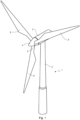
- Fig. 1 shows a modern wind turbine 1 comprising a wind turbine tower 2, a nacelle 3 arranged on top of the wind turbine tower 2, and a rotor defining a rotor plane.
- the nacelle 3 is connected to the wind turbine tower 2, e.g. via a yaw bearing unit.
- the rotor comprises a hub 4 and a number of wind turbine blades 5. Here three wind turbine blades are shown, but the rotor may comprise more or fewer wind turbine blades 5.
- the hub 4 is connected to a drive train, e.g. a generator, located in the wind turbine 1 via a rotation shaft.
- the hub 4 comprises a mounting interface for each wind turbine blade 5.
- a pitch bearing unit 6 is optionally connected to this mounting interface and further to a blade root of the wind turbine blade 5.
- Fig. 2 shows a schematic view of the wind turbine blade 5 which extends in a longitudinal direction from a blade root 7 to a tip end 8.
- the wind turbine blade 5 further extends in a chordwise direction from a leading edge 9 to a trailing edge 10.
- the wind turbine blade 5 comprises a blade shell 11 having two opposite facing side surfaces defining a pressure side 12 and a suction side 13 respectively.
- the blade shell 11 further defines a blade root portion 14, an aerodynamic blade portion 15, and a transition portion 16 between the blade root portion 14 and the aerodynamic blade portion 15.
- the blade root portion 14 has a substantially circular or elliptical cross-section (indicated by dashed lines).
- the blade root portion 14 together with a load carrying structure e.g. a main laminate combined with a shear web or a box beam, are configured to add structural strength to the wind turbine blade 5 and transfer the dynamic loads to the hub 4.
- the load carrying structure extends between the pressure side 12 and the suction side 13 and further in the longitudinal direction.
- the blade aerodynamic blade portion 15 has an aerodynamically shaped cross-section (indicated by dashed lines) designed to generate lift.
- the cross-sectional profile of the blade shell 11 gradually transforms from the circular or elliptical profile into the aerodynamic profile in the transition portion 16.
- the wind turbine blade 5 has a longitudinal length 17 of at least 35 metres, preferably at least 50 metres.
- the wind turbine blade 5 further has a chord length 18 as function of the length 17, wherein the maximum chord length is found between the blade aerodynamic blade portion 15 and the transition portion 16.
- Fig. 3 shows a first exemplary embodiment of a noise reducing device 19 configured for attachment to the wind turbine blade 5.
- An array of noise reducing devices 19 is optionally arranged on the wind turbine blade 5 along the trailing edge 10, as indicated in fig. 2 .
- the noise reducing device 19 comprises a plurality of airflow modifying elements 20 having a first profile which extends from a first proximal end 21 to a first end 22.
- the noise reducing device 19 further comprises a plurality of noise reducing elements 23 having a second profile which extends from a second proximal end 24 to a second end 25.
- the airflow modifying elements 20 and the noise reducing elements 23 face in opposite longitudinal directions.
- the airflow modifying elements 20, the base part 26 and the noise reducing elements 23 has first local side surface 27 and an opposite second side surface (see figs. 8 and 9 ). Here both the first and second local side surfaces form a continuous side surface.
- a base part 26 is arranged between the first and second proximal ends 21, 24 and extends in a transverse direction.
- the base part 26 is formed by a single continuous element, as indicated in figs. 4 and 5 .
- the base part 26 is formed by a first sub-part 26a and at least a second sub-part 26b, as indicated in fig. 3 .
- the airflow modifying elements 20 and the noise reducing elements 23 are shaped as serrations having the same overall triangular profile.
- the airflow modifying elements 20 have a first local length and the noise reducing elements 23 have a second local length. As illustrated in fig. 3 , the first local length is less than the second local length, e.g. less than 50% of the second local length.
- the airflow modifying elements 20 further have a first local width and the noise reducing elements 23 further have a second local width. As illustrated in fig. 3 , the first local width is less than the second local width, e.g. less than 33% of the second local width.
- Fig. 4 shows a second exemplary embodiment of the noise reducing device 19 where the noise reducing elements 23' have a different profile than the noise reducing elements 23.
- the noise reducing elements 23' comprises a thickened portion arranged on the second local side surface, wherein this thickened portion tapers from the second proximal end 24 to the second end 25.
- the thickened portion has a local edge surface 28 facing the first end 22.
- the noise reducing elements 23' has a substantially three-dimensional pyramid-shaped profile.
- the noise reducing elements 23 in fig. 3 has a substantially two-dimensional pyramid-shaped profile.
- Fig. 5 shows a third exemplary embodiment of the noise reducing device 19 where the airflow modifying elements 20' have a different profile than the noise reducing elements 23.
- the noise reducing elements 23 have a triangular profile while the airflow modifying elements 20' have a semi-elliptical profile.
- Fig. 6 shows a fourth exemplary embodiment of the noise reducing device 19 where the airflow modifying elements 20" have different geometrical properties than the airflow modifying elements 20 of fig. 3 .
- the first local length is less than the second local length, e.g. between 50% to 100% of the second local length.
- the first local width is less than the second local width, e.g. between 33% to 100% of the second local width.
- the first local width may further be between 50% to 100% of the second local width, as indicated in fig. 7 .
- Fig. 7 shows a non-claimed fifth exemplary embodiment of the noise reducing device 19' where the base part 26 is omitted.
- the first and second proximal ends 21, 24 form a common proximal end.
- Fig. 8 shows a first embodiment of the airflow modifying elements 20 seen in the transverse direction.
- the second local side surface 29 of at least the airflow modifying elements 20 and the base part 26 form a flat side surface facing the respective side surface of the wind turbine blade 5 when attached, as illustrated in figs. 10 and 11 .
- the first local side surfaces 27' of the airflow modifying elements 20 and the base part 26 face in an opposite flapwise direction when attached.
- the first local side surface 27' of at least the airflow modifying elements 20 has a tapered profile in the longitudinal direction, which tapers from the first proximal end 21 to the first end 22.
- Fig. 9 shows a second embodiment of the airflow modifying elements 20 wherein the first local side surface 27" of at least the airflow modifying elements 20 has a tapered profile in the transverse direction.
- the first local side surface 27" tapers from a central line 30 to the opposite peripheral edges 31 of the airflow modifying elements 20.
- the first local side surface 27 of the airflow modifying elements 20 has a combined tapered profile which tapers in both the longitudinal direction and the transverse direction.
- Fig. 10 shows a cross-sectional view of the noise reducing device 19 attached to the wind turbine blade 5.
- the wind turbine blade 5 has a sharp trailing edge 10'.
- the airflow modifying elements 20 and the base part 26 are arranged on the pressure side 12, alternatively on the suction side 13, of the wind turbine blade 5.
- the airflow modifying elements 20 and/or the base part 26 are/is attached to the respective side surface of the wind turbine blade 5.
- the second proximal end 24 is placed in a retracted position relative to, alternatively aligned with, the sharp trailing edge 10'.
- the noise reducing elements 23 thus project freely from the trailing edge 10' so that the second end 25 is located behind the trailing edge 10'.
- Fig. 11 shows a cross-sectional view of the noise reducing device 19 attached to the wind turbine blade 5 with a truncated trailing edge 10".
- the truncated trailing edge 10" has a trailing edge surface 32 facing the second end 25 of the noise reducing device 19.
- the thickened portion of the noise reducing elements 23 is arranged relative to this truncated trailing edge 10" so that the local edge surface 28 is contacting the trailing edge surface 32.
- the thickened portion is further attached to the truncated trailing edge 10", e.g. using an adhesive between the local edge surface 28 and the trailing edge surface 32.
Claims (11)
- Dispositif de réduction de bruit (19) pour une pale d'éolienne (5), s'étendant dans une direction longitudinale depuis une première extrémité (22) jusqu'à une deuxième extrémité (25), et ayant une première surface latérale locale (27) et une deuxième surface latérale locale (29) agencées entre la première extrémité (22) et la deuxième extrémité, la deuxième surface latérale locale étant une surface latérale sensiblement plate, dans lequel le dispositif de réduction de bruit (19) est configuré à des fins de fixation sur une surface latérale de la pale d'éolienne (5), le dispositif de réduction de bruit (19) comportant une pluralité d'éléments de modification de flux d'air (20) et une pluralité d'éléments de réduction de bruit (23), les éléments de modification de flux d'air (20) s'étendant depuis une première extrémité proximale (21) jusqu'à la première extrémité (22), les éléments de réduction de bruit (23) s'étendant depuis une deuxième extrémité proximale (24) orientée à l'opposé jusqu'à la deuxième extrémité (25), dans lequel les éléments de modification de flux d'air (20) et les éléments de réduction de bruit (23) s'étendent dans des directions longitudinales opposées, la deuxième surface latérale locale des éléments de modification de flux d'air (20) est configurée pour être fixée directement sur ladite surface latérale de la pale d'éolienne (5), et le dispositif de réduction de bruit (19) comportant par ailleurs au moins une partie de base (26), dans lequel ladite au moins une partie de base (26) s'étend depuis la première extrémité proximale (21) jusqu'à la deuxième extrémité proximale (24).
- Dispositif de réduction de bruit selon la revendication 1, caractérisé en ce qu'au moins les éléments de modification de flux d'air (20) ou les éléments de réduction de bruit (23) sont formés d'un seul tenant avec ladite au moins une partie de base (26).
- Dispositif de réduction de bruit selon l'une quelconque des revendications 1 à 2, caractérisé en ce que chaque élément de modification de flux d'air (20) a une première longueur mesurée depuis la première extrémité proximale (21) jusqu'à la première extrémité (22) et chaque élément de réduction de bruit (23) a une deuxième longueur mesurée depuis la deuxième extrémité proximale (24) jusqu'à la deuxième extrémité (25), dans lequel la première longueur est égale ou inférieure à la deuxième longueur.
- Dispositif de réduction de bruit selon l'une quelconque des revendications 1 à 3, caractérisé en ce que chaque élément de modification de flux d'air (20) a une première largeur mesurée le long de la première extrémité proximale (21) et chaque élément de réduction de bruit (23) a une deuxième largeur mesurée le long de la deuxième extrémité proximale (24), dans lequel la première largeur est égale ou inférieure à la deuxième largeur.
- Dispositif de réduction de bruit selon l'une quelconque des revendications 1 à 4, caractérisé en ce que chaque élément de modification de flux d'air (20) a un premier profil et chaque élément de réduction de bruit (23) a un deuxième profil, dans lequel le premier profil est différent du deuxième profil.
- Dispositif de réduction de bruit selon l'une quelconque des revendications 1 à 5, caractérisé en ce que ladite première surface latérale locale (27) d'au moins les éléments de modification de flux d'air (20) a un profil effilé dans une direction allant dans le sens de la largeur et/ou dans une direction allant dans le sens de la longueur.
- Dispositif de réduction de bruit selon l'une quelconque des revendications 1 à 6, caractérisé en ce qu'au moins les éléments de modification de flux d'air (20) sont des dentelures.
- Dispositif de réduction de bruit selon la revendication 7, caractérisé en ce que les éléments de réduction de bruit (23) sont des dentelures.
- Pale d'éolienne (5) pour une éolienne, s'étendant dans une direction longitudinale depuis une extrémité de pied (7) jusqu'à une extrémité de bout (8) de la pale et par ailleurs dans une direction allant dans le sens de la corde depuis un bord d'attaque (9) jusqu'à un bord de fuite (10), la pale d'éolienne comportant une première surface latérale définissant un côté en pression (12) et une deuxième surface latérale définissant un côté en dépression (13), dans laquelle au moins un dispositif de réduction de bruit (19) est fixé sur l'une desdites première et deuxième surfaces latérales, ledit au moins un dispositif de réduction de bruit (19) est agencé par rapport au bord de fuite (10), caractérisée en ce que ledit au moins un dispositif de réduction de bruit (19) est configuré selon l'une quelconque des revendications 1 à 8.
- Pale d'éolienne selon la revendication 9, caractérisée en ce qu'au moins les éléments de modification de flux d'air (20) ou au moins une partie de base (26) dudit au moins un dispositif de réduction de bruit (19) sont agencés sur ladite l'une des première et deuxième surfaces latérales et s'étendent vers le bord d'attaque (9).
- Pale d'éolienne selon la revendication 9 ou la revendication 10, caractérisée en ce que le bord de fuite (10) est un bord de fuite tronqué (10") ayant une surface de bord de fuite (32), dans laquelle le dispositif de réduction de bruit (19) a une surface de bord locale (28) s'étendant le long d'au moins une partie de ladite surface de bord de fuite (32) dans une direction allant dans le sens du battement.
Applications Claiming Priority (2)
| Application Number | Priority Date | Filing Date | Title |
|---|---|---|---|
| EP17172212.7A EP3406892A1 (fr) | 2017-05-22 | 2017-05-22 | Pale de turbine éolienne comprenant un dispositif de réduction de bruit |
| PCT/EP2018/063379 WO2018215461A1 (fr) | 2017-05-22 | 2018-05-22 | Pale d'éolienne dotée d'un dispositif de réduction de bruit |
Publications (2)
| Publication Number | Publication Date |
|---|---|
| EP3631197A1 EP3631197A1 (fr) | 2020-04-08 |
| EP3631197B1 true EP3631197B1 (fr) | 2023-10-25 |
Family
ID=58772406
Family Applications (2)
| Application Number | Title | Priority Date | Filing Date |
|---|---|---|---|
| EP17172212.7A Pending EP3406892A1 (fr) | 2017-05-22 | 2017-05-22 | Pale de turbine éolienne comprenant un dispositif de réduction de bruit |
| EP18724294.6A Active EP3631197B1 (fr) | 2017-05-22 | 2018-05-22 | Pale de turbine éolienne comprenant un dispositif de réduction de bruit |
Family Applications Before (1)
| Application Number | Title | Priority Date | Filing Date |
|---|---|---|---|
| EP17172212.7A Pending EP3406892A1 (fr) | 2017-05-22 | 2017-05-22 | Pale de turbine éolienne comprenant un dispositif de réduction de bruit |
Country Status (5)
| Country | Link |
|---|---|
| US (1) | US11448183B2 (fr) |
| EP (2) | EP3406892A1 (fr) |
| DK (1) | DK3631197T3 (fr) |
| MA (1) | MA48932A (fr) |
| WO (1) | WO2018215461A1 (fr) |
Families Citing this family (4)
| Publication number | Priority date | Publication date | Assignee | Title |
|---|---|---|---|---|
| DE102017112742A1 (de) * | 2017-06-09 | 2018-12-13 | Wobben Properties Gmbh | Rotorblatt für eine Windenergieanlage und Windenergieanlage |
| GB202001046D0 (en) * | 2020-01-24 | 2020-03-11 | Lm Wind Power As | Wind turbine blade damping device |
| EP4172492A1 (fr) * | 2020-06-29 | 2023-05-03 | Vestas Wind Systems A/S | Éolienne |
| WO2022136256A1 (fr) * | 2020-12-22 | 2022-06-30 | Lm Wind Power A/S | Procédé de fabrication d'une coque de pale d'éolienne |
Family Cites Families (21)
| Publication number | Priority date | Publication date | Assignee | Title |
|---|---|---|---|---|
| CN102007291A (zh) | 2008-08-06 | 2011-04-06 | 三菱重工业株式会社 | 风车翼和使用该风车翼的风力发电装置 |
| US20110268558A1 (en) * | 2010-12-20 | 2011-11-03 | General Electric Company | Noise reducer for rotor blade in wind turbine |
| US8414261B2 (en) * | 2011-05-31 | 2013-04-09 | General Electric Company | Noise reducer for rotor blade in wind turbine |
| WO2013076008A1 (fr) * | 2011-11-23 | 2013-05-30 | Lm Wind Power A/S | Pale de turbine éolienne |
| US20130164141A1 (en) * | 2011-12-22 | 2013-06-27 | General Electric Company | Blade with semi-rigid trailing edge |
| US20140072441A1 (en) * | 2012-09-12 | 2014-03-13 | Michael J. Asheim | Load and noise mitigation system for wind turbine blades |
| US20150050154A1 (en) * | 2013-05-23 | 2015-02-19 | Kristian R. DIXON | Airfoil trailing edge apparatus for noise reduction |
| EP2851554A1 (fr) * | 2013-09-18 | 2015-03-25 | Siemens Aktiengesellschaft | Agencement permettant de réduire l'émission de bruit |
| US10731626B2 (en) * | 2013-12-20 | 2020-08-04 | Lm Wp Patent Holding A/S | Wind turbine blade having deployable aerodynamic devices |
| US9476406B2 (en) * | 2014-04-14 | 2016-10-25 | Siemens Aktiengesellschaft | Vortex generators aligned with trailing edge features on wind turbine blade |
| US20150316025A1 (en) | 2014-05-01 | 2015-11-05 | Siemens Energy, Inc. | Aerodynamic device for a rotor blade of a wind turbine |
| CA2948068A1 (fr) * | 2014-05-06 | 2015-11-12 | Siemens Aktiengesellschaft | Moyen de reduction de bruit pour aube de rotor d'une turbine eolienne |
| EP3099926A1 (fr) * | 2014-06-18 | 2016-12-07 | Siemens Aktiengesellschaft | Pale de rotor dotée de moyens de réduction du bruit |
| DK3096003T3 (da) * | 2015-05-21 | 2021-05-10 | Siemens Gamesa Renewable Energy As | Rotorvinge med takker til en vindmølle |
| WO2017180192A1 (fr) * | 2016-04-15 | 2017-10-19 | Siemens Aktiengesellschaft | Pale de rotor à bord de fuite dentelé |
| US10523406B2 (en) | 2015-06-28 | 2019-12-31 | RF DSP Inc. | Single channel full duplex wireless base station or access point |
| DK3329117T3 (da) * | 2015-09-03 | 2021-04-19 | Siemens Gamesa Renewable Energy As | Vindmøllevinge med bagkanttap |
| WO2017044099A1 (fr) * | 2015-09-10 | 2017-03-16 | Siemens Aktiengesellschaft | Cloison de décrochage réductrice de bruit pour pale d'éolienne |
| US10240576B2 (en) * | 2015-11-25 | 2019-03-26 | General Electric Company | Wind turbine noise reduction with acoustically absorbent serrations |
| US11536245B2 (en) * | 2017-01-26 | 2022-12-27 | General Electric Company | Rotor blade assembly and a wind turbine having the rotor blade assembly |
| US10465652B2 (en) * | 2017-01-26 | 2019-11-05 | General Electric Company | Vortex generators for wind turbine rotor blades having noise-reducing features |
-
2017
- 2017-05-22 EP EP17172212.7A patent/EP3406892A1/fr active Pending
-
2018
- 2018-05-22 MA MA048932A patent/MA48932A/fr unknown
- 2018-05-22 DK DK18724294.6T patent/DK3631197T3/da active
- 2018-05-22 US US16/614,633 patent/US11448183B2/en active Active
- 2018-05-22 EP EP18724294.6A patent/EP3631197B1/fr active Active
- 2018-05-22 WO PCT/EP2018/063379 patent/WO2018215461A1/fr active Application Filing
Also Published As
| Publication number | Publication date |
|---|---|
| MA48932A (fr) | 2020-04-08 |
| US11448183B2 (en) | 2022-09-20 |
| EP3406892A1 (fr) | 2018-11-28 |
| WO2018215461A1 (fr) | 2018-11-29 |
| DK3631197T3 (da) | 2023-12-11 |
| US20200149507A1 (en) | 2020-05-14 |
| EP3631197A1 (fr) | 2020-04-08 |
Similar Documents
| Publication | Publication Date | Title |
|---|---|---|
| EP3631197B1 (fr) | Pale de turbine éolienne comprenant un dispositif de réduction de bruit | |
| EP2778392B1 (fr) | Pale de rotor d'éolienne | |
| EP2368035B1 (fr) | Pale d'éolienne dotée d'un déflecteur avec une séparation efficace de la circulation de l'air | |
| DK2801720T3 (en) | Luftstrømsmodificerende device for a rotor blade of a wind turbine | |
| EP3348826B1 (fr) | Pale de turbine éolienne comprenant un dispositif de réduction de bruit de bord de fuite | |
| EP3051125B1 (fr) | Générateur de tourbillon pour pale de rotor | |
| EP2799710B1 (fr) | Ensemble de pale de rotor comportant des générateurs de tourbillons pour éolienne | |
| EP2394911B1 (fr) | Pales d'éoliennes avec éléments de vortex aérodynamiques contrôlables | |
| EP3085952B1 (fr) | Configuration d'écoulement d'air pour une pale de rotor de turbine éolienne | |
| CN110242493B (zh) | 用于风力涡轮机叶片的锯齿状后缘板 | |
| EP2868916B1 (fr) | Rallonges de corde destinées à un ensemble de pale de rotor d'éolienne | |
| EP2198153B1 (fr) | Pale d'éolienne avec un moyen de contrôle de couche limite immergée comprenant des sous-canaux de croisement | |
| DK177907B1 (en) | Wind turbine blade with wave shaped trailing edge | |
| EP3390812B1 (fr) | Système à plaque de séparation pour une pale de turbine éolienne dentelée | |
| EP2479423B1 (fr) | Élément de pale de rotor d'éolienne | |
| US11473555B2 (en) | Wind turbine blade comprising a trailing edge noise reducing device | |
| EP2851557A1 (fr) | Pale d'eolienne avec des volets aérodynamiques placés au pied de la pale |
Legal Events
| Date | Code | Title | Description |
|---|---|---|---|
| STAA | Information on the status of an ep patent application or granted ep patent |
Free format text: STATUS: UNKNOWN |
|
| STAA | Information on the status of an ep patent application or granted ep patent |
Free format text: STATUS: THE INTERNATIONAL PUBLICATION HAS BEEN MADE |
|
| PUAI | Public reference made under article 153(3) epc to a published international application that has entered the european phase |
Free format text: ORIGINAL CODE: 0009012 |
|
| STAA | Information on the status of an ep patent application or granted ep patent |
Free format text: STATUS: REQUEST FOR EXAMINATION WAS MADE |
|
| 17P | Request for examination filed |
Effective date: 20191213 |
|
| AK | Designated contracting states |
Kind code of ref document: A1 Designated state(s): AL AT BE BG CH CY CZ DE DK EE ES FI FR GB GR HR HU IE IS IT LI LT LU LV MC MK MT NL NO PL PT RO RS SE SI SK SM TR |
|
| AX | Request for extension of the european patent |
Extension state: BA ME |
|
| DAX | Request for extension of the european patent (deleted) | ||
| RAV | Requested validation state of the european patent: fee paid |
Extension state: TN Effective date: 20191213 Extension state: MA Effective date: 20191213 |
|
| STAA | Information on the status of an ep patent application or granted ep patent |
Free format text: STATUS: EXAMINATION IS IN PROGRESS |
|
| 17Q | First examination report despatched |
Effective date: 20210729 |
|
| RAP1 | Party data changed (applicant data changed or rights of an application transferred) |
Owner name: LM WIND POWER A/S |
|
| GRAP | Despatch of communication of intention to grant a patent |
Free format text: ORIGINAL CODE: EPIDOSNIGR1 |
|
| STAA | Information on the status of an ep patent application or granted ep patent |
Free format text: STATUS: GRANT OF PATENT IS INTENDED |
|
| INTG | Intention to grant announced |
Effective date: 20230112 |
|
| GRAJ | Information related to disapproval of communication of intention to grant by the applicant or resumption of examination proceedings by the epo deleted |
Free format text: ORIGINAL CODE: EPIDOSDIGR1 |
|
| STAA | Information on the status of an ep patent application or granted ep patent |
Free format text: STATUS: EXAMINATION IS IN PROGRESS |
|
| GRAP | Despatch of communication of intention to grant a patent |
Free format text: ORIGINAL CODE: EPIDOSNIGR1 |
|
| STAA | Information on the status of an ep patent application or granted ep patent |
Free format text: STATUS: GRANT OF PATENT IS INTENDED |
|
| INTC | Intention to grant announced (deleted) | ||
| INTG | Intention to grant announced |
Effective date: 20230523 |
|
| P01 | Opt-out of the competence of the unified patent court (upc) registered |
Effective date: 20230522 |
|
| GRAS | Grant fee paid |
Free format text: ORIGINAL CODE: EPIDOSNIGR3 |
|
| GRAA | (expected) grant |
Free format text: ORIGINAL CODE: 0009210 |
|
| STAA | Information on the status of an ep patent application or granted ep patent |
Free format text: STATUS: THE PATENT HAS BEEN GRANTED |
|
| AK | Designated contracting states |
Kind code of ref document: B1 Designated state(s): AL AT BE BG CH CY CZ DE DK EE ES FI FR GB GR HR HU IE IS IT LI LT LU LV MC MK MT NL NO PL PT RO RS SE SI SK SM TR |
|
| REG | Reference to a national code |
Ref country code: GB Ref legal event code: FG4D |
|
| REG | Reference to a national code |
Ref country code: CH Ref legal event code: EP |
|
| REG | Reference to a national code |
Ref country code: DE Ref legal event code: R096 Ref document number: 602018059926 Country of ref document: DE |
|
| REG | Reference to a national code |
Ref country code: IE Ref legal event code: FG4D |
|
| REG | Reference to a national code |
Ref country code: DK Ref legal event code: T3 Effective date: 20231207 |
|
| REG | Reference to a national code |
Ref country code: LT Ref legal event code: MG9D |
|
| REG | Reference to a national code |
Ref country code: NL Ref legal event code: MP Effective date: 20231025 |
|
| REG | Reference to a national code |
Ref country code: AT Ref legal event code: MK05 Ref document number: 1624894 Country of ref document: AT Kind code of ref document: T Effective date: 20231025 |
|
| PG25 | Lapsed in a contracting state [announced via postgrant information from national office to epo] |
Ref country code: NL Free format text: LAPSE BECAUSE OF FAILURE TO SUBMIT A TRANSLATION OF THE DESCRIPTION OR TO PAY THE FEE WITHIN THE PRESCRIBED TIME-LIMIT Effective date: 20231025 |
|
| PG25 | Lapsed in a contracting state [announced via postgrant information from national office to epo] |
Ref country code: GR Free format text: LAPSE BECAUSE OF FAILURE TO SUBMIT A TRANSLATION OF THE DESCRIPTION OR TO PAY THE FEE WITHIN THE PRESCRIBED TIME-LIMIT Effective date: 20240126 |
|
| PG25 | Lapsed in a contracting state [announced via postgrant information from national office to epo] |
Ref country code: IS Free format text: LAPSE BECAUSE OF FAILURE TO SUBMIT A TRANSLATION OF THE DESCRIPTION OR TO PAY THE FEE WITHIN THE PRESCRIBED TIME-LIMIT Effective date: 20240225 |
|
| PG25 | Lapsed in a contracting state [announced via postgrant information from national office to epo] |
Ref country code: LT Free format text: LAPSE BECAUSE OF FAILURE TO SUBMIT A TRANSLATION OF THE DESCRIPTION OR TO PAY THE FEE WITHIN THE PRESCRIBED TIME-LIMIT Effective date: 20231025 |