EP3631162B1 - Methods and systems for downhole sensing and communications in wells - Google Patents
Methods and systems for downhole sensing and communications in wells Download PDFInfo
- Publication number
- EP3631162B1 EP3631162B1 EP18809046.8A EP18809046A EP3631162B1 EP 3631162 B1 EP3631162 B1 EP 3631162B1 EP 18809046 A EP18809046 A EP 18809046A EP 3631162 B1 EP3631162 B1 EP 3631162B1
- Authority
- EP
- European Patent Office
- Prior art keywords
- tubing
- production
- encapsulated
- sensor
- casing
- Prior art date
- Legal status (The legal status is an assumption and is not a legal conclusion. Google has not performed a legal analysis and makes no representation as to the accuracy of the status listed.)
- Active
Links
- 238000000034 method Methods 0.000 title claims description 26
- 238000004891 communication Methods 0.000 title description 20
- 238000004519 manufacturing process Methods 0.000 claims description 107
- 239000012530 fluid Substances 0.000 claims description 52
- 238000002347 injection Methods 0.000 claims description 27
- 239000007924 injection Substances 0.000 claims description 27
- 230000005465 channeling Effects 0.000 claims description 15
- 230000001105 regulatory effect Effects 0.000 claims description 3
- 238000007599 discharging Methods 0.000 claims description 2
- 230000005540 biological transmission Effects 0.000 claims 3
- 238000010586 diagram Methods 0.000 description 8
- XLYOFNOQVPJJNP-UHFFFAOYSA-N water Substances O XLYOFNOQVPJJNP-UHFFFAOYSA-N 0.000 description 6
- 239000003921 oil Substances 0.000 description 5
- 239000004020 conductor Substances 0.000 description 4
- 239000000463 material Substances 0.000 description 3
- 239000002184 metal Substances 0.000 description 3
- 229910052751 metal Inorganic materials 0.000 description 3
- 229920001343 polytetrafluoroethylene Polymers 0.000 description 3
- 239000004810 polytetrafluoroethylene Substances 0.000 description 3
- 239000004677 Nylon Substances 0.000 description 2
- 239000010779 crude oil Substances 0.000 description 2
- 229910001026 inconel Inorganic materials 0.000 description 2
- 238000005259 measurement Methods 0.000 description 2
- 150000002739 metals Chemical class 0.000 description 2
- 239000000203 mixture Substances 0.000 description 2
- 229920001778 nylon Polymers 0.000 description 2
- 230000008054 signal transmission Effects 0.000 description 2
- 229910001220 stainless steel Inorganic materials 0.000 description 2
- 239000010935 stainless steel Substances 0.000 description 2
- -1 without limitation Substances 0.000 description 2
- 229910000831 Steel Inorganic materials 0.000 description 1
- 230000015572 biosynthetic process Effects 0.000 description 1
- 239000011248 coating agent Substances 0.000 description 1
- 238000000576 coating method Methods 0.000 description 1
- 230000008021 deposition Effects 0.000 description 1
- 230000000694 effects Effects 0.000 description 1
- 230000005611 electricity Effects 0.000 description 1
- 239000000446 fuel Substances 0.000 description 1
- 239000007789 gas Substances 0.000 description 1
- 239000007788 liquid Substances 0.000 description 1
- 238000012544 monitoring process Methods 0.000 description 1
- 210000002445 nipple Anatomy 0.000 description 1
- 239000004033 plastic Substances 0.000 description 1
- 229920003023 plastic Polymers 0.000 description 1
- 239000010959 steel Substances 0.000 description 1
- 239000000126 substance Substances 0.000 description 1
- 238000012546 transfer Methods 0.000 description 1
Images


Classifications
-
- E—FIXED CONSTRUCTIONS
- E21—EARTH DRILLING; MINING
- E21B—EARTH DRILLING, e.g. DEEP DRILLING; OBTAINING OIL, GAS, WATER, SOLUBLE OR MELTABLE MATERIALS OR A SLURRY OF MINERALS FROM WELLS
- E21B47/00—Survey of boreholes or wells
- E21B47/12—Means for transmitting measuring-signals or control signals from the well to the surface, or from the surface to the well, e.g. for logging while drilling
- E21B47/13—Means for transmitting measuring-signals or control signals from the well to the surface, or from the surface to the well, e.g. for logging while drilling by electromagnetic energy, e.g. radio frequency
-
- H—ELECTRICITY
- H04—ELECTRIC COMMUNICATION TECHNIQUE
- H04B—TRANSMISSION
- H04B13/00—Transmission systems characterised by the medium used for transmission, not provided for in groups H04B3/00 - H04B11/00
-
- E—FIXED CONSTRUCTIONS
- E21—EARTH DRILLING; MINING
- E21B—EARTH DRILLING, e.g. DEEP DRILLING; OBTAINING OIL, GAS, WATER, SOLUBLE OR MELTABLE MATERIALS OR A SLURRY OF MINERALS FROM WELLS
- E21B17/00—Drilling rods or pipes; Flexible drill strings; Kellies; Drill collars; Sucker rods; Cables; Casings; Tubings
- E21B17/003—Drilling rods or pipes; Flexible drill strings; Kellies; Drill collars; Sucker rods; Cables; Casings; Tubings with electrically conducting or insulating means
-
- E—FIXED CONSTRUCTIONS
- E21—EARTH DRILLING; MINING
- E21B—EARTH DRILLING, e.g. DEEP DRILLING; OBTAINING OIL, GAS, WATER, SOLUBLE OR MELTABLE MATERIALS OR A SLURRY OF MINERALS FROM WELLS
- E21B43/00—Methods or apparatus for obtaining oil, gas, water, soluble or meltable materials or a slurry of minerals from wells
- E21B43/12—Methods or apparatus for controlling the flow of the obtained fluid to or in wells
- E21B43/121—Lifting well fluids
- E21B43/122—Gas lift
-
- E—FIXED CONSTRUCTIONS
- E21—EARTH DRILLING; MINING
- E21B—EARTH DRILLING, e.g. DEEP DRILLING; OBTAINING OIL, GAS, WATER, SOLUBLE OR MELTABLE MATERIALS OR A SLURRY OF MINERALS FROM WELLS
- E21B47/00—Survey of boreholes or wells
- E21B47/10—Locating fluid leaks, intrusions or movements
- E21B47/103—Locating fluid leaks, intrusions or movements using thermal measurements
Definitions
- the field of the invention relates generally to production wells, and more specifically, to methods and systems for downhole sensing and communications in a production well.
- US 2006/124318 A1 discloses providing telemetry between a downhole device located in a wellbore and an up-hole device.
- downhole sensing equipment e.g., temperature and pressure sensors
- At least some known production wells use one or more cables that extend from the surface through the production well to the downhole sensing equipment.
- the cables supply power to the downhole sensing equipment and/or provide communication between the downhole sensing equipment and the surface.
- at least some known cables increase the cost to assemble the production well and reduce the space available for other components in the production well (e.g., pipes, conduits, mandrels, etc.). Accordingly, it is desirable to wirelessly provide power and communications between surface equipment and downhole sensing equipment in a production well.
- the systems and methods described herein provide power and communications for downhole sensing equipment. These methods and systems use tubing to transmit power to downhole sensing equipment, and provide wireless communication between surface equipment and the downhole sensing equipment.
- encapsulated tubing provides a current flow path between the surface equipment and the downhole sensing equipment.
- production tubing acts a ground to provide a return path for the electrical current.
- the electrical current provides power to the downhole sensing equipment and enables the transmission of signals between the surface equipment and the downhole sensing equipment. Accordingly, the systems and methods provide wireless power and communications between downhole components and the surface, and eliminate the need to run power and communication cables down through a well.
- FIG. 1 is a schematic diagram of an exemplary production system 100.
- Production system 100 includes an artificial lift system 102 and a well 104.
- well 104 is a hole drilled for extracting production fluid 110, such as crude oil, water, and/or gas, from the ground.
- Artificial lift system 102 is configured to facilitate extracting fluid through well 104.
- a fluid such as gas is injected into well 104 and proceeds downhole.
- Artificial lift system 102 includes an injection control valve 105 which regulates a quantity of fluid injected into well 104. While the fluid is being injected, an injection temperature sensor 106, an injection pressure sensor 108, and an injection meter 109 take measurements at the surface.
- artificial lift system 102 has any configuration that enables production system 100 to operate as described herein.
- artificial lift system 102 is configured to inject any fluid including, without limitation, chemicals, gas, liquids, and/or fuel.
- artificial lift system 102 is omitted.
- a flow tube pressure sensor 118 measures the wellhead tubing pressure.
- a flow line 120 channels fluids 110 to a separator 122.
- Separator 122 separates fluid 110 into gas 124, oil 126, and water 128.
- Oil 126 is removed by separator 122 and the amount of oil retrieved is metered by oil meter 130.
- Water 128 is also removed by separator 122 and the amount of water retrieved is metered by water meter 132.
- Gas 124 is siphoned out of separator 122 through gas line 134.
- multi-phase flow meter 136 replaces oil meter 130 and water meter 132.
- a multi-phase flow meter 136 is used to measure production.
- Some gas 124 is transferred to a gas pipeline 140 through a gas production meter 138.
- some gas 124 is transferred to a compressor 148 though a flow line 146.
- compressor 148 includes a compressor engine 150.
- Compressor 148 compresses gas 124
- a compressor controller 152 regulates the speed of compressor engine 150.
- compressor 148 is driven by gas or electricity.
- the speed of compressor engine 150 is measured in regulating the revolutions per minute (RPM) of compressor engine 150.
- a compressor back pressure valve 156 ensures sufficient discharge pressure for the well and recycles excessive gas back to the compressor suction valve 154.
- a compressor recycle valve 158 is an overflow valve that reintroduces gas 124 above a certain pressure back into compressor 148 through compressor suction valve 154.
- Gas 124 flows from compressor 148 to well 104. The amount of gas that is injected into well 104 is measured by injection meter 109.
- gas 124 is compressed by compressor 148.
- the amount of gas 124 injected into well 104 is controlled by injection control valve 105 and measured by injection meter 109.
- gas 124 mixes with fluids 110.
- the mixture of fluids 110 and gas 124 is pushed up through tubing 114 to the top of well 104 by reservoir pressure 112.
- the mixture of gas 124 and fluids 110 travels through flow line 120 into separator 122, where fluids 110 and gas 124 are separated.
- a quantity of gas 124 is routed back to compressor 148 to be reinjected into well 104.
- Excess gas 124 is routed to gas pipeline 140 to be sold or otherwise used elsewhere. In some embodiments, some gas 124 is used to power compressor engine 150.
- production system 100 includes a controller 160 installed at the surface of production system 100.
- Controller 160 receives signals from one or more downhole communication or telemetry systems located in well 104, as described herein. Controller 160 processes the received signals (e.g., by decrypting or converting the information therein) and generates one or more outputs based on the processed signals. The outputs may, for example, cause information to be displayed on a display device 162 communicatively coupled to controller 160 for viewing by a human operator.
- a power supply 164 is coupled to controller 160.
- power supply 164 is wirelessly coupled to sensors 117.
- Power supply 164 provides electrical current to controller 160, sensors 117, and/or other components of production system 100.
- power supply 164 provides direct current and/or alternating current.
- power supply 164 provides 110 Volt, 220 Volt, and 440 Volt alternating current.
- power supply 164 provides any power that enables well 200 to operate as described herein
- FIG. 2 is a schematic diagram of a portion of an exemplary well 200, such as well 104 (shown in FIG. 1 ).
- FIG. 3 is a cross-section of well 200 taken along section line 3-3.
- Well 200 includes production tubing 202, such as tubing 114 (shown in FIG. 1 ), that extends through a casing 204.
- An annulus 206 is defined between production tubing 202 and casing 204.
- well 200 includes encapsulated tubing 208 located within production tubing 202.
- encapsulated tubing 208 is located within annulus 206 between production tubing 202 and casing 204.
- production tubing 202 and encapsulated tubing 208 are configured to channel fluids.
- Production tubing 202 has a first diameter and is configured to channel fluids 110 (shown in FIG. 1 ) upwards through casing 204 towards a wellhead.
- Encapsulated tubing 208 has a second diameter less than the first diameter and is configured to channel fluids downhole in well 104.
- Encapsulated tubing 208 includes a discharge port 210 configured to discharge the fluids.
- artificial lift system 102 (shown in FIG. 1 ) is configured to direct injection fluids through a capillary string including encapsulated tubing 208 and encapsulated tubing 208 discharges the injection fluids downhole into well 200.
- well 200 includes any tubing that enables well 200 to operate as described herein.
- encapsulated tubing 208 is configured to channel fluids 110 (shown in FIG. 1 ) towards the wellhead.
- well 200 includes a downhole tool 212.
- Downhole tool 212 includes at least one sensor 214 and a communications device 216.
- Downhole tool 212 is coupled to an end of encapsulated tubing 208 and is positioned in casing 204.
- casing 204 includes positioning features such as a landing nipple and landing tool 218 to locate downhole tool 212.
- Communications device 216 is configured to communicate with controller 160 (shown in FIG. 1 ).
- well 200 includes any downhole tool that enables well 200 to operate as described herein.
- sensor 214 is configured to detect downhole conditions within casing 204.
- sensor 214 includes, without limitation, pressure sensors, temperature sensors, position determination sensors (e.g., ultrasonic sensors), accelerometers, flow sensors (e.g., acoustic flow sensors), fluid property sensors, conductivity sensors, salinity sensors, microwave water-cut sensors, vortex flow sensors, nuclear densometers, etc.
- well 200 includes any sensor 214 that enables well 200 to operate as described herein.
- sensor 214 includes a pressure sensor in communication with a pressure port to facilitate measuring, for example, a pressure within a gas lift mandrel 220 and/or production tubing 202.
- encapsulated tubing 208 includes a conductive sidewall 222 and an insulative layer 224.
- Conductive sidewall 222 is cylindrical and defines a channel 225 for injection fluid.
- Conductive sidewall 222 includes a conductive material and is configured to conduct electrical current to sensors 214.
- conductive sidewall 222 is constructed of a metal such as stainless steel and/or Inconel. Accordingly, encapsulated tubing 208 acts as a mono-conductor. In alternative embodiments, encapsulated tubing 208 includes any conductive sidewall 222 that enables well 200 to operate as described herein.
- production tubing 202 includes a conductive material.
- production tubing 202 is constructed of metals such as steel. Accordingly, production tubing 202 acts as ground tubing and is configured to conduct electrical current from sensors 214 towards the wellhead.
- insulative layer 224 surrounds conductive sidewall 222 and is configured to inhibit electrical current from discharging to conductive components within casing 204 during operation of well 200 when electrical current is flowing through conductive sidewall 222 and/or production tubing 202.
- insulative layer 224 is constructed of non-conductive or electrically insulative materials such as plastics (e.g., nylon and polytetrafluoroethylene (PTFE).
- PTFE polytetrafluoroethylene
- insulative layer 224 is a coating on conductive sidewall 222.
- encapsulated tubing 208 includes any insulative layer 224 that enables encapsulated tubing 208 to function as described herein.
- a portion of conductive sidewall 222 extends beyond insulative layer 224 and couples to downhole tool 212. Specifically, an end of conductive sidewall 222 extends beyond insulative layer 224 and is in contact with power electronics and/or communication device 216 of downhole tool 212.
- encapsulated tubing 208 and sensor 214 are coupled in any manner that enables well 200 to operate as described herein.
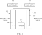
- FIG. 4 is a schematic diagram of current flow in the production well 200.
- Encapsulated tubing 208 and production tubing 202 define a current flow path 226 between sensor 214 and power supply 164.
- encapsulated tubing 208 is coupled to power supply 164 and sensor 214 and conveys electrical power from power supply 164 to sensor 214.
- Sensor 214 is configured to operate using the electrical power received from power supply 164.
- Production tubing 202 acts as ground tubing to provide a return path 228 for the electrical current.
- encapsulated tubing 208 and production tubing 202 transfer signals between sensor 214 and controller 160. Accordingly, encapsulated tubing 208 and production tubing 202 eliminate the need for one or more cables in well 200 to provide power to downhole equipment, and to provide communications between downhole equipment and the surface.
- controller 160 is configured to regulate flow of an electrical current through conductive sidewall 222. Accordingly, controller 160 regulates the power supplied to sensors 214. In addition, controller 160 (shown in FIG. 1 ) regulates the electrical current to communicate using encapsulated tubing 208. For example, in some embodiments, controller 160 (shown in FIG. 1 ) is configured to send signals through encapsulated tubing 208 to sensor 214. In addition, controller 160 is configured to monitor the electric current transferred through encapsulated tubing 208 and/or production tubing 202 and receive signals sent through encapsulated tubing 208 and/or production tubing 202 from sensor 214 and/or other components of well 200.
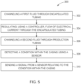
- FIG. 5 is a flow diagram of an exemplary method 300 of sensing downhole conditions of production well 200.
- method 300 generally includes channeling 302 an injection fluid through encapsulated tubing 208, regulating 304 flow of electrical current through conductive sidewall 222, channeling 306 a production fluid through production tubing 202, detecting 308 a condition within casing 204 using sensor 214, and sending 310 a signal relating to the condition.
- channeling 302 includes channeling the injection fluid from the wellhead downhole through encapsulated tubing 208.
- the injection fluid is used to facilitate operation of well 200.
- injection fluid is directed from a capillary string including encapsulated tubing 208.
- the injection fluid is directed along casing 204 to remediate deposition on casing 204, reduce the formation of scale on casing 204, and/or remove material or bridging extending across casing 204.
- encapsulated tubing 208 is used to channel any fluid that enables well 200 to operate as described herein.
- artificial lift system 102 (shown in FIG. 1 ) directs fluid downhole through encapsulated tubing 208 to increase pressure in well 200 and facilitate production of well 200.
- encapsulated tubing 208 is located anywhere within casing 204 (shown in FIG. 3 ) that enables well 200 to operate as described herein.
- channeling 302 includes channeling the injection fluid through encapsulated tubing 208 located on an exterior of production tubing 202.
- channeling 302 includes channeling the injection fluid through encapsulated tubing 208 located within production tubing 202.
- channeling 306 includes channeling production fluid such as crude oil and/or gas through production tubing 202 towards a wellhead of production well 200.
- production tubing 202 is used to channel any fluid that enables well 200 to operate as described herein.
- signals are sent through encapsulated tubing 208 and/or production tubing 202 between sensor 214 and controller 160.
- Controller 160 is configured to determine conditions of well 200 based on the signals. For example, in some embodiments, controller 160 determines pressure and temperature. Controller 160 is configured to regulate components of well 200 based on the determined conditions to control operating conditions of well 200. In further embodiments, controller 160 sends signals through encapsulated tubing 208 and/or production tubing 202 toward sensor 214 to control sensor 214. In alternative embodiments, controller 160 and/or sensor 214 send any signals that enable well 200 to operate as described herein.
- sensor 214 is operated using the electrical current flowing through encapsulated tubing 208 and/or production tubing 202.
- power is supplied continuously to sensor 214 during operation of sensor 214 from power supply 164.
- the current from power supply 164 is used to charge a power source of sensor 214.
- sensor 214 is powered in any manner that enables well 200 to operate as described herein.
- FIG. 6 is a cross-section of an exemplary embodiment of a production well 400 including a plurality of encapsulated tubing 402.
- Production well 400 includes production tubing 404, such as tubing 114 (shown in FIG. 1 ), that extends through a casing 406.
- An annulus 408 is defined between production tubing 404 and casing 406.
- production well 400 includes a plurality of encapsulated tubing 402 located within production tubing 202.
- encapsulated tubing 402 is located within annulus 408 between production tubing 404 and casing 406.
- each encapsulated tubing 402 includes a conductive sidewall 410.
- conductive sidewall 410 includes conductive metals such as stainless steel and Inconel.
- An insulative layer 412 surrounds encapsulated tubing 402 and electrically isolates each conductive sidewall 410.
- Insulative layer 412 includes electrically insulative materials such as nylon or PTFE.
- encapsulated tubing 402 includes any insulative layer 412 that enables encapsulated tubing 402 to function as described herein.
- each encapsulated tubing 402 includes a separate insulative layer 412.
- conductive sidewall 410 of at least one encapsulated tubing 402 is configured to act as a conductor to conduct current downhole and conductive sidewall 410 of at least one other encapsulated tubing 402 is configured to act as a return for the electrical current.
- production well 400 includes any encapsulated tubing 402 that enables production well 400 to operate as described herein.
- production well 400 includes pluralities of encapsulated tubing 402 coupled in separate packs.
- some encapsulated tubing 402 does not necessarily include conductive sidewall 410.
- the above-described systems and methods provide power and communications for downhole sensing equipment. These methods and systems use tubing to transmit power to downhole sensing equipment, and provide wireless communication between surface equipment and the downhole sensing equipment.
- encapsulated tubing provides a current flow path between the surface equipment and the downhole sensing equipment.
- production tubing acts a ground to provide a return path for the electrical current.
- the electrical current provides power to the downhole sensing equipment and enables the transmission of signals between the surface equipment and the downhole sensing equipment. Accordingly, the systems and methods provide wireless power and communications between downhole components and the surface, and eliminate the need to run power and communication cables down through a well.
- An exemplary technical effect of the methods, systems, and apparatus described herein includes at least one of: (a) providing a wireless system for communicating data between downhole components and the surface; (b) utilizing tubing to provide power to downhole components; (c) eliminating obstructions and additional equipment in production wells; (d) provide downhole wireless communication and power system that is compatible with existing systems; and (e) increase real-time monitoring capabilities of downhole conditions.
- Exemplary embodiments of method and systems for downhole sensing and communications in production wells are described above in detail.
- the method and systems described herein are not limited to the specific embodiments described herein, but rather, components of systems or steps of the methods may be utilized independently and separately from other components or steps described herein.
- the methods may also be used in combination with multiple different production systems, and are not limited to practice with only the production systems as described herein.
- the methods may also be used with other tubing, and are not limited to practice with only the tubing as described herein.
- the exemplary embodiments may be implemented and utilized in connection with many other production systems to be operated as described herein.
Description
- The field of the invention relates generally to production wells, and more specifically, to methods and systems for downhole sensing and communications in a production well.
-
US 2006/124318 A1 discloses providing telemetry between a downhole device located in a wellbore and an up-hole device. - In at least some known production wells, downhole sensing equipment (e.g., temperature and pressure sensors) are used below the surface to monitor conditions below the surface. At least some known production wells use one or more cables that extend from the surface through the production well to the downhole sensing equipment. The cables supply power to the downhole sensing equipment and/or provide communication between the downhole sensing equipment and the surface. However, at least some known cables increase the cost to assemble the production well and reduce the space available for other components in the production well (e.g., pipes, conduits, mandrels, etc.). Accordingly, it is desirable to wirelessly provide power and communications between surface equipment and downhole sensing equipment in a production well.
- The present invention is defined in the accompanying claims.
- These and other features, aspects, and advantages of the present disclosure will become better understood when the following detailed description is read with reference to the accompanying drawings in which like characters represent like parts throughout the drawings, wherein:
-
FIG 1 is a schematic diagram of an exemplary production system; -
FIG. 2 is a schematic diagram of a portion of an exemplary production well for use with the system shown inFIG. 1 ; -
FIG. 3 is a cross-section of the production well shown inFIG. 2 taken along section line 3-3; -
FIG. 4 is a schematic diagram of current flow in the production well shown inFIG. 2 ; -
FIG. 5 is a flow diagram of an exemplary method for sensing downhole conditions of the production well shown inFIG. 2 ; and -
FIG. 6 is a cross-section of an exemplary embodiment of a production well including a plurality of encapsulated tubing. - Unless otherwise indicated, the drawings provided herein are meant to illustrate features of embodiments of the disclosure. These features are believed to be applicable in a wide variety of systems comprising one or more embodiments of the disclosure. As such, the drawings are not meant to include all conventional features known by those of ordinary skill in the art to be required for the practice of the embodiments disclosed herein.
- The systems and methods described herein provide power and communications for downhole sensing equipment. These methods and systems use tubing to transmit power to downhole sensing equipment, and provide wireless communication between surface equipment and the downhole sensing equipment. For example, in some embodiments, encapsulated tubing provides a current flow path between the surface equipment and the downhole sensing equipment. In addition, in some embodiments, production tubing acts a ground to provide a return path for the electrical current. The electrical current provides power to the downhole sensing equipment and enables the transmission of signals between the surface equipment and the downhole sensing equipment. Accordingly, the systems and methods provide wireless power and communications between downhole components and the surface, and eliminate the need to run power and communication cables down through a well.
-
FIG. 1 is a schematic diagram of anexemplary production system 100.Production system 100 includes anartificial lift system 102 and a well 104. In the exemplary embodiment, well 104 is a hole drilled for extractingproduction fluid 110, such as crude oil, water, and/or gas, from the ground.Artificial lift system 102 is configured to facilitate extracting fluid through well 104. For example, in some embodiments, a fluid such as gas is injected into well 104 and proceeds downhole.Artificial lift system 102 includes aninjection control valve 105 which regulates a quantity of fluid injected into well 104. While the fluid is being injected, aninjection temperature sensor 106, aninjection pressure sensor 108, and aninjection meter 109 take measurements at the surface. The injected fluid induces a reduction in the density of one ormore fluids 110 inwell 104, so thatreservoir pressure 112 is sufficient to pushfluids 110 up atubing 114. In the exemplary embodiment, one ormore lift valves 116 assist the flow offluids 110 uptubing 114. In some embodiments, downhole temperature andpressure sensors 117 take measurements at downhole locations. In alternative embodiments,artificial lift system 102 has any configuration that enablesproduction system 100 to operate as described herein. For example, in some embodiments,artificial lift system 102 is configured to inject any fluid including, without limitation, chemicals, gas, liquids, and/or fuel. In further embodiments,artificial lift system 102 is omitted. - In the exemplary embodiment, at the top of well 104, a flow
tube pressure sensor 118 measures the wellhead tubing pressure. Aflow line 120channels fluids 110 to aseparator 122.Separator 122 separatesfluid 110 intogas 124,oil 126, andwater 128.Oil 126 is removed byseparator 122 and the amount of oil retrieved is metered byoil meter 130.Water 128 is also removed byseparator 122 and the amount of water retrieved is metered bywater meter 132.Gas 124 is siphoned out ofseparator 122 throughgas line 134. In some embodiments,multi-phase flow meter 136 replacesoil meter 130 andwater meter 132. In these embodiments, amulti-phase flow meter 136 is used to measure production. Somegas 124 is transferred to agas pipeline 140 through agas production meter 138. In the exemplary embodiment, somegas 124 is transferred to acompressor 148 though aflow line 146. -
Gas 124 enterscompressor 148 throughcompressor suction valve 154. In the exemplary embodiment,compressor 148 includes acompressor engine 150.Compressor 148compresses gas 124, and acompressor controller 152 regulates the speed ofcompressor engine 150. In some embodiments,compressor 148 is driven by gas or electricity. In further embodiments, the speed ofcompressor engine 150 is measured in regulating the revolutions per minute (RPM) ofcompressor engine 150. A compressorback pressure valve 156 ensures sufficient discharge pressure for the well and recycles excessive gas back to thecompressor suction valve 154. Acompressor recycle valve 158 is an overflow valve that reintroducesgas 124 above a certain pressure back intocompressor 148 throughcompressor suction valve 154.Gas 124 flows fromcompressor 148 to well 104. The amount of gas that is injected into well 104 is measured byinjection meter 109. - During normal operation of
production system 100,gas 124 is compressed bycompressor 148. The amount ofgas 124 injected intowell 104 is controlled byinjection control valve 105 and measured byinjection meter 109. In well 104,gas 124 mixes withfluids 110. The mixture offluids 110 andgas 124 is pushed up throughtubing 114 to the top of well 104 byreservoir pressure 112. The mixture ofgas 124 andfluids 110 travels throughflow line 120 intoseparator 122, wherefluids 110 andgas 124 are separated. A quantity ofgas 124 is routed back tocompressor 148 to be reinjected intowell 104.Excess gas 124 is routed togas pipeline 140 to be sold or otherwise used elsewhere. In some embodiments, somegas 124 is used topower compressor engine 150. - In the exemplary embodiment,
production system 100 includes acontroller 160 installed at the surface ofproduction system 100.Controller 160 receives signals from one or more downhole communication or telemetry systems located in well 104, as described herein.Controller 160 processes the received signals (e.g., by decrypting or converting the information therein) and generates one or more outputs based on the processed signals. The outputs may, for example, cause information to be displayed on adisplay device 162 communicatively coupled tocontroller 160 for viewing by a human operator. - Also, in the exemplary embodiment, a
power supply 164 is coupled tocontroller 160. In addition, as described herein,power supply 164 is wirelessly coupled tosensors 117.Power supply 164 provides electrical current tocontroller 160,sensors 117, and/or other components ofproduction system 100. For example, in some embodiments,power supply 164 provides direct current and/or alternating current. In further embodiments,power supply 164 provides 110 Volt, 220 Volt, and 440 Volt alternating current. In alternative embodiments,power supply 164 provides any power that enables well 200 to operate as described herein -
FIG. 2 is a schematic diagram of a portion of anexemplary well 200, such as well 104 (shown inFIG. 1 ).FIG. 3 is a cross-section of well 200 taken along section line 3-3. Well 200 includesproduction tubing 202, such as tubing 114 (shown inFIG. 1 ), that extends through acasing 204. Anannulus 206 is defined betweenproduction tubing 202 andcasing 204. In addition, well 200 includes encapsulatedtubing 208 located withinproduction tubing 202. In alternative embodiments, encapsulatedtubing 208 is located withinannulus 206 betweenproduction tubing 202 andcasing 204. - In the exemplary embodiment,
production tubing 202 and encapsulatedtubing 208 are configured to channel fluids.Production tubing 202 has a first diameter and is configured to channel fluids 110 (shown inFIG. 1 ) upwards throughcasing 204 towards a wellhead. Encapsulatedtubing 208 has a second diameter less than the first diameter and is configured to channel fluids downhole inwell 104. Encapsulatedtubing 208 includes adischarge port 210 configured to discharge the fluids. For example, in some embodiments, artificial lift system 102 (shown inFIG. 1 ) is configured to direct injection fluids through a capillary string including encapsulatedtubing 208 and encapsulatedtubing 208 discharges the injection fluids downhole intowell 200. In alternative embodiments, well 200 includes any tubing that enables well 200 to operate as described herein. For example, in some embodiments, encapsulatedtubing 208 is configured to channel fluids 110 (shown inFIG. 1 ) towards the wellhead. - Also, in the exemplary embodiment, well 200 includes a
downhole tool 212.Downhole tool 212 includes at least onesensor 214 and acommunications device 216.Downhole tool 212 is coupled to an end of encapsulatedtubing 208 and is positioned incasing 204. In some embodiments, casing 204 includes positioning features such as a landing nipple andlanding tool 218 to locatedownhole tool 212.Communications device 216 is configured to communicate with controller 160 (shown inFIG. 1 ). In alternative embodiments, well 200 includes any downhole tool that enables well 200 to operate as described herein. - Moreover, in the exemplary embodiment,
sensor 214 is configured to detect downhole conditions withincasing 204. For example, in some embodiments,sensor 214 includes, without limitation, pressure sensors, temperature sensors, position determination sensors (e.g., ultrasonic sensors), accelerometers, flow sensors (e.g., acoustic flow sensors), fluid property sensors, conductivity sensors, salinity sensors, microwave water-cut sensors, vortex flow sensors, nuclear densometers, etc. In alternative embodiments, well 200 includes anysensor 214 that enables well 200 to operate as described herein. For example, in some embodiments,sensor 214 includes a pressure sensor in communication with a pressure port to facilitate measuring, for example, a pressure within agas lift mandrel 220 and/orproduction tubing 202. - Also, in the exemplary embodiment, encapsulated
tubing 208 includes aconductive sidewall 222 and aninsulative layer 224.Conductive sidewall 222 is cylindrical and defines achannel 225 for injection fluid.Conductive sidewall 222 includes a conductive material and is configured to conduct electrical current tosensors 214. For example, in some embodiments,conductive sidewall 222 is constructed of a metal such as stainless steel and/or Inconel. Accordingly, encapsulatedtubing 208 acts as a mono-conductor. In alternative embodiments, encapsulatedtubing 208 includes anyconductive sidewall 222 that enables well 200 to operate as described herein. - In addition, in the exemplary embodiment,
production tubing 202 includes a conductive material. For example, in some embodiments,production tubing 202 is constructed of metals such as steel. Accordingly,production tubing 202 acts as ground tubing and is configured to conduct electrical current fromsensors 214 towards the wellhead. - Moreover, in the exemplary embodiment,
insulative layer 224 surroundsconductive sidewall 222 and is configured to inhibit electrical current from discharging to conductive components withincasing 204 during operation of well 200 when electrical current is flowing throughconductive sidewall 222 and/orproduction tubing 202. In the exemplary embodiments,insulative layer 224 is constructed of non-conductive or electrically insulative materials such as plastics (e.g., nylon and polytetrafluoroethylene (PTFE). In some embodiments,insulative layer 224 is a coating onconductive sidewall 222. In alternative embodiments, encapsulatedtubing 208 includes anyinsulative layer 224 that enables encapsulatedtubing 208 to function as described herein. - Also, in the exemplary embodiment, a portion of
conductive sidewall 222 extends beyondinsulative layer 224 and couples todownhole tool 212. Specifically, an end ofconductive sidewall 222 extends beyondinsulative layer 224 and is in contact with power electronics and/orcommunication device 216 ofdownhole tool 212. In alternative embodiments, encapsulatedtubing 208 andsensor 214 are coupled in any manner that enables well 200 to operate as described herein. -
FIG. 4 is a schematic diagram of current flow in theproduction well 200. Encapsulatedtubing 208 andproduction tubing 202 define acurrent flow path 226 betweensensor 214 andpower supply 164. In particular, encapsulatedtubing 208 is coupled topower supply 164 andsensor 214 and conveys electrical power frompower supply 164 tosensor 214.Sensor 214 is configured to operate using the electrical power received frompower supply 164.Production tubing 202 acts as ground tubing to provide areturn path 228 for the electrical current. In addition, encapsulatedtubing 208 andproduction tubing 202 transfer signals betweensensor 214 andcontroller 160. Accordingly, encapsulatedtubing 208 andproduction tubing 202 eliminate the need for one or more cables in well 200 to provide power to downhole equipment, and to provide communications between downhole equipment and the surface. - Also, in the exemplary embodiment,
controller 160 is configured to regulate flow of an electrical current throughconductive sidewall 222. Accordingly,controller 160 regulates the power supplied tosensors 214. In addition, controller 160 (shown inFIG. 1 ) regulates the electrical current to communicate using encapsulatedtubing 208. For example, in some embodiments, controller 160 (shown inFIG. 1 ) is configured to send signals through encapsulatedtubing 208 tosensor 214. In addition,controller 160 is configured to monitor the electric current transferred through encapsulatedtubing 208 and/orproduction tubing 202 and receive signals sent through encapsulatedtubing 208 and/orproduction tubing 202 fromsensor 214 and/or other components ofwell 200. -
FIG. 5 is a flow diagram of anexemplary method 300 of sensing downhole conditions ofproduction well 200. In reference toFIGS. 4 and5 ,method 300 generally includes channeling 302 an injection fluid through encapsulatedtubing 208, regulating 304 flow of electrical current throughconductive sidewall 222, channeling 306 a production fluid throughproduction tubing 202, detecting 308 a condition withincasing 204 usingsensor 214, and sending 310 a signal relating to the condition. - In the exemplary embodiment, channeling 302 includes channeling the injection fluid from the wellhead downhole through encapsulated
tubing 208. In some embodiments, the injection fluid is used to facilitate operation ofwell 200. For example, in some embodiments, injection fluid is directed from a capillary string including encapsulatedtubing 208. The injection fluid is directed alongcasing 204 to remediate deposition oncasing 204, reduce the formation of scale oncasing 204, and/or remove material or bridging extending acrosscasing 204. In alternative embodiments, encapsulatedtubing 208 is used to channel any fluid that enables well 200 to operate as described herein. For example, in some embodiments, artificial lift system 102 (shown inFIG. 1 ) directs fluid downhole through encapsulatedtubing 208 to increase pressure in well 200 and facilitate production ofwell 200. - Also, in the exemplary embodiment, encapsulated
tubing 208 is located anywhere within casing 204 (shown inFIG. 3 ) that enables well 200 to operate as described herein. For example, in some embodiments, channeling 302 includes channeling the injection fluid through encapsulatedtubing 208 located on an exterior ofproduction tubing 202. In further embodiments, channeling 302 includes channeling the injection fluid through encapsulatedtubing 208 located withinproduction tubing 202. - In addition, in the exemplary embodiment, channeling 306 includes channeling production fluid such as crude oil and/or gas through
production tubing 202 towards a wellhead ofproduction well 200. In alternative embodiments,production tubing 202 is used to channel any fluid that enables well 200 to operate as described herein. - Moreover, in the exemplary embodiment, signals are sent through encapsulated
tubing 208 and/orproduction tubing 202 betweensensor 214 andcontroller 160.Controller 160 is configured to determine conditions of well 200 based on the signals. For example, in some embodiments,controller 160 determines pressure and temperature.Controller 160 is configured to regulate components of well 200 based on the determined conditions to control operating conditions of well 200. In further embodiments,controller 160 sends signals through encapsulatedtubing 208 and/orproduction tubing 202 towardsensor 214 to controlsensor 214. In alternative embodiments,controller 160 and/orsensor 214 send any signals that enable well 200 to operate as described herein. - In addition, in the exemplary embodiment,
sensor 214 is operated using the electrical current flowing through encapsulatedtubing 208 and/orproduction tubing 202. In some embodiments, power is supplied continuously tosensor 214 during operation ofsensor 214 frompower supply 164. In further embodiments, the current frompower supply 164 is used to charge a power source ofsensor 214. In alternative embodiments,sensor 214 is powered in any manner that enables well 200 to operate as described herein. -
FIG. 6 is a cross-section of an exemplary embodiment of a production well 400 including a plurality of encapsulatedtubing 402. Production well 400 includesproduction tubing 404, such as tubing 114 (shown inFIG. 1 ), that extends through acasing 406. Anannulus 408 is defined betweenproduction tubing 404 andcasing 406. In addition, production well 400 includes a plurality of encapsulatedtubing 402 located withinproduction tubing 202. In alternative embodiments, encapsulatedtubing 402 is located withinannulus 408 betweenproduction tubing 404 andcasing 406. - Also, in the exemplary embodiment, the plurality of encapsulated
tubing 402 are coupled together to form a single pack. Each encapsulatedtubing 402 includes aconductive sidewall 410. In the exemplary embodiment,conductive sidewall 410 includes conductive metals such as stainless steel and Inconel. Aninsulative layer 412 surrounds encapsulatedtubing 402 and electrically isolates eachconductive sidewall 410.Insulative layer 412 includes electrically insulative materials such as nylon or PTFE. In alternative embodiments, encapsulatedtubing 402 includes anyinsulative layer 412 that enables encapsulatedtubing 402 to function as described herein. For example, in some embodiments, each encapsulatedtubing 402 includes aseparate insulative layer 412. - In addition, in the exemplary embodiment,
conductive sidewall 410 of at least one encapsulatedtubing 402 is configured to act as a conductor to conduct current downhole andconductive sidewall 410 of at least one other encapsulatedtubing 402 is configured to act as a return for the electrical current. In alternative embodiments, production well 400 includes any encapsulatedtubing 402 that enables production well 400 to operate as described herein. For example, in some embodiments, production well 400 includes pluralities of encapsulatedtubing 402 coupled in separate packs. In further embodiments, some encapsulatedtubing 402 does not necessarily includeconductive sidewall 410. - The above-described systems and methods provide power and communications for downhole sensing equipment. These methods and systems use tubing to transmit power to downhole sensing equipment, and provide wireless communication between surface equipment and the downhole sensing equipment. For example, in some embodiments, encapsulated tubing provides a current flow path between the surface equipment and the downhole sensing equipment. In addition, in some embodiments, production tubing acts a ground to provide a return path for the electrical current. The electrical current provides power to the downhole sensing equipment and enables the transmission of signals between the surface equipment and the downhole sensing equipment. Accordingly, the systems and methods provide wireless power and communications between downhole components and the surface, and eliminate the need to run power and communication cables down through a well.
- An exemplary technical effect of the methods, systems, and apparatus described herein includes at least one of: (a) providing a wireless system for communicating data between downhole components and the surface; (b) utilizing tubing to provide power to downhole components; (c) eliminating obstructions and additional equipment in production wells; (d) provide downhole wireless communication and power system that is compatible with existing systems; and (e) increase real-time monitoring capabilities of downhole conditions.
- Exemplary embodiments of method and systems for downhole sensing and communications in production wells are described above in detail. The method and systems described herein are not limited to the specific embodiments described herein, but rather, components of systems or steps of the methods may be utilized independently and separately from other components or steps described herein. For example, the methods may also be used in combination with multiple different production systems, and are not limited to practice with only the production systems as described herein. Additionally, the methods may also be used with other tubing, and are not limited to practice with only the tubing as described herein. Rather, the exemplary embodiments may be implemented and utilized in connection with many other production systems to be operated as described herein.
- This written description uses examples to disclose the embodiments, including the best mode, and also to enable any person skilled in the art to practice the embodiments, including making and using any devices or systems and performing any incorporated methods. The scope of protection of the current invention is defined by the appended claims.
Claims (14)
- A production well (200) comprising:a casing (204);encapsulated tubing (208) positioned within said casing (204) and configured to channel an injection fluid through said casing, said encapsulated tubing (208) including a conductive sidewall (222) defining a channel for the injection fluid;an insulative layer (224) surrounding said conductive sidewall (222);a controller (160) configured to regulate flow of an electrical current through said conductive sidewall (222);production tubing (202) positioned within said casing (204) and configured to channel a production fluid through said casing, wherein said insulative layer (224) is configured to inhibit transmission of the electrical current between said conductive sidewall (222) and said production tubing (202); andat least one sensor (214) positioned within said casing (204) to detect downhole conditions of said production well, wherein said conductive sidewall (222) is configured to conduct the electrical current toward said at least one sensor (214);wherein said production tubing (202) is configured to channel the production fluid towards a wellhead of said production well (200) and has a first diameter and wherein said encapsulated tubing (208) is configured to channel the injection fluid away from the wellhead, wherein said encapsulated tubing (208) has a second diameter less than the first diameter;characterized in that said encapsulated tubing (208) is located within said production tubing (202).
- The production well in accordance with Claim 1, wherein an artificial lift system is configured to direct the injection fluid through said encapsulated tubing (208).
- The production well in accordance with Claim 1, wherein said encapsulated tubing (208) is configured to transmit signals between said controller (160) and said at least one sensor (214).
- The production well in accordance with Claim 1, wherein said production tubing (202) is configured to transmit signals between said at least one sensor (214) and said controller (160).
- The production well in accordance with Claim 1, further comprising a power source (164) coupled to said conductive sidewall (222), wherein said conductive sidewall (222) is configured to convey electrical power between said power source (164) and said at least one sensor (214), and wherein said at least one sensor (214) is configured to operate using the electrical power.
- The production well in accordance with Claim 5, wherein said production tubing (202) extends from said at least one sensor (214) to a wellhead and is configured to provide a return path for the electrical current.
- The production well in accordance with Claim 1, wherein said encapsulated tubing (402) is a first encapsulated tubing, said production well further comprising a second encapsulated tubing (402), wherein said second encapsulated tubing is configured to provide a return path for the electrical current.
- The production well in accordance with Claim 7, wherein said first encapsulated tubing (402) and said second encapsulated tubing (402) are coupled together in a pack, and wherein said insulative layer (412) is configured to inhibit transmission of the electrical current between said first encapsulated tubing (402) and said second encapsulated tubing (402).
- A method (300) of sensing downhole conditions in a production well, said method comprising:channeling (302) an injection fluid through encapsulated tubing (208) positioned within a casing (204) of the production well (200), the encapsulated tubing (208) including a conductive sidewall (222);regulating (304), using a controller (160), flow of electrical current through the conductive sidewall (222), wherein an insulative layer (224) surrounds the conductive sidewall (222) and is configured to inhibit the electrical current from discharging to conductive components within the casing (204);directing (306) a production fluid through production tubing (202) positioned within the casing (204), wherein the insulative layer (224) is configured to inhibit transmission of the electrical current between the conductive sidewall (222) and the production tubing (202);detecting (308) a condition within the casing (204) using at least one sensor (214) positioned with the casing (204), wherein the conductive sidewall (222) is configured to conduct the electrical current toward the at least one sensor (214); andsending a signal relating to the condition within the casing from the at least one sensor (214) to the controller (160);wherein directing a production fluid through production tubing (202) positioned within the casing (204) comprises directing the production fluid towards a wellhead of the production well, the production tubing having a first diameter and wherein channeling an injection fluid through encapsulated tubing (208) positioned within a casing of the production well comprises channeling the injection fluid from the wellhead, wherein the encapsulated tubing (208) has a second diameter less than the first diameter;characterized in that channeling an injection fluid through encapsulated tubing (208) positioned within a casing (204) of the production well further comprises channeling the injection fluid through the encapsulated tubing (208) located within the production tubing (202).
- The method in accordance with Claim 9, further comprising directing the injection fluid through the encapsulated tubing (208) using an artificial lift system.
- The method in accordance with Claim 9, further comprising transmitting, using the encapsulated tubing (208), signals between the controller (160) and the at least one sensor (214).
- The method in accordance with Claim 9, further comprising transmitting, using the production tubing (202), signals between the controller (160) and the at least one sensor (214).
- The method in accordance with Claim 9, further comprising operating the at least one sensor (214) using electrical power conveyed through the conductive sidewall (222), wherein the conductive sidewall (222) is coupled to a power source (164) at a wellhead of the production well and wherein the conductive sidewall (222) is configured to convey the electrical power between the power source (164) and said at least one sensor (214).
- The method in accordance with Claim 13, further comprising directing the electrical current from the at least one sensor (214) toward the power source (164) through the production tubing (202).
Applications Claiming Priority (2)
| Application Number | Priority Date | Filing Date | Title |
|---|---|---|---|
| US15/608,647 US10598006B2 (en) | 2017-05-30 | 2017-05-30 | Methods and systems for downhole sensing and communications in wells |
| PCT/US2018/031698 WO2018222352A1 (en) | 2017-05-30 | 2018-05-08 | Methods and systems for downhole sensing and communications in wells |
Publications (3)
| Publication Number | Publication Date |
|---|---|
| EP3631162A1 EP3631162A1 (en) | 2020-04-08 |
| EP3631162A4 EP3631162A4 (en) | 2021-03-24 |
| EP3631162B1 true EP3631162B1 (en) | 2023-07-19 |
Family
ID=64454988
Family Applications (1)
| Application Number | Title | Priority Date | Filing Date |
|---|---|---|---|
| EP18809046.8A Active EP3631162B1 (en) | 2017-05-30 | 2018-05-08 | Methods and systems for downhole sensing and communications in wells |
Country Status (4)
| Country | Link |
|---|---|
| US (1) | US10598006B2 (en) |
| EP (1) | EP3631162B1 (en) |
| AR (1) | AR111968A1 (en) |
| WO (1) | WO2018222352A1 (en) |
Families Citing this family (1)
| Publication number | Priority date | Publication date | Assignee | Title |
|---|---|---|---|---|
| CN110244349B (en) * | 2019-07-01 | 2021-01-26 | 中国铁建重工集团股份有限公司 | In-hole detector |
Family Cites Families (28)
| Publication number | Priority date | Publication date | Assignee | Title |
|---|---|---|---|---|
| CA1222444A (en) | 1981-02-23 | 1987-06-02 | Roy R. Vann | Method of firing perforating gun and simultaneously recording downhole pressure |
| US4505155A (en) | 1981-07-13 | 1985-03-19 | Sperry-Sun, Inc. | Borehole pressure measuring system |
| US4510551A (en) | 1984-05-21 | 1985-04-09 | Endeco Canada Limited | Portable memory module |
| US5419188A (en) | 1991-05-20 | 1995-05-30 | Otis Engineering Corporation | Reeled tubing support for downhole equipment module |
| US5467083A (en) | 1993-08-26 | 1995-11-14 | Electric Power Research Institute | Wireless downhole electromagnetic data transmission system and method |
| US5969242A (en) * | 1998-04-30 | 1999-10-19 | Lockheed Martin Idaho Technologies Company | Isobaric groundwater well |
| GB2338253B (en) | 1998-06-12 | 2000-08-16 | Schlumberger Ltd | Power and signal transmission using insulated conduit for permanent downhole installations |
| US6633236B2 (en) * | 2000-01-24 | 2003-10-14 | Shell Oil Company | Permanent downhole, wireless, two-way telemetry backbone using redundant repeaters |
| US20020036085A1 (en) * | 2000-01-24 | 2002-03-28 | Bass Ronald Marshall | Toroidal choke inductor for wireless communication and control |
| CN2451735Y (en) | 2000-11-03 | 2001-10-03 | 中国石油天然气股份有限公司 | Capillary down-hole pressure monitoring transmitter |
| US6434372B1 (en) | 2001-01-12 | 2002-08-13 | The Regents Of The University Of California | Long-range, full-duplex, modulated-reflector cell phone for voice/data transmission |
| US20040253734A1 (en) | 2001-11-13 | 2004-12-16 | Cully Firmin | Down-hole pressure monitoring system |
| US7230542B2 (en) | 2002-05-23 | 2007-06-12 | Schlumberger Technology Corporation | Streamlining data transfer to/from logging while drilling tools |
| US20050145416A1 (en) | 2004-01-05 | 2005-07-07 | Halliburton Energy Services, Inc. | Method and system of transferring data gathered by downhole devices to surface devices |
| US7493962B2 (en) * | 2004-12-14 | 2009-02-24 | Schlumberger Technology Corporation | Control line telemetry |
| US7750808B2 (en) | 2005-05-06 | 2010-07-06 | Halliburton Energy Services, Inc. | Data retrieval tags |
| US7336199B2 (en) * | 2006-04-28 | 2008-02-26 | Halliburton Energy Services, Inc | Inductive coupling system |
| US8230915B2 (en) * | 2007-03-28 | 2012-07-31 | Schlumberger Technology Corporation | Apparatus, system, and method for determining injected fluid vertical placement |
| WO2009088501A1 (en) | 2008-01-05 | 2009-07-16 | Truax, Jerome, A. | System and method for memory pulsed-neutron gamma-ray spectroscopy logging |
| US8810428B2 (en) * | 2008-09-02 | 2014-08-19 | Schlumberger Technology Corporation | Electrical transmission between rotating and non-rotating members |
| US20110191028A1 (en) | 2010-02-04 | 2011-08-04 | Schlumberger Technology Corporation | Measurement devices with memory tags and methods thereof |
| CA2811528C (en) | 2010-09-17 | 2016-02-02 | Schlumberger Canada Limited | Downhole delivery of chemicals with a micro-tubing system |
| US20140190706A1 (en) | 2013-01-02 | 2014-07-10 | Schlumberger Technology Corporation | Encapsulating an electric submersible pump cable in coiled tubing |
| CN203130075U (en) | 2013-01-16 | 2013-08-14 | 江苏苏仪集团有限公司 | Wireless measurement instrument for temperature and pressure of oil well head |
| US9260961B2 (en) | 2013-06-14 | 2016-02-16 | Baker Hughes Incorporated | Modular monitoring assembly |
| US9810059B2 (en) | 2014-06-30 | 2017-11-07 | Saudi Arabian Oil Company | Wireless power transmission to downhole well equipment |
| WO2016122446A1 (en) * | 2015-01-26 | 2016-08-04 | Schlumberger Canada Limited | Electrically conductive fiber optic slickline for coiled tubing operations |
| US9708905B2 (en) | 2015-06-05 | 2017-07-18 | Sensor Developments As | Wellbore wireless thermal conductivity quartz transducer with waste-heat management system |
-
2017
- 2017-05-30 US US15/608,647 patent/US10598006B2/en active Active
-
2018
- 2018-05-08 EP EP18809046.8A patent/EP3631162B1/en active Active
- 2018-05-08 WO PCT/US2018/031698 patent/WO2018222352A1/en unknown
- 2018-05-30 AR ARP180101420A patent/AR111968A1/en active IP Right Grant
Also Published As
| Publication number | Publication date |
|---|---|
| AR111968A1 (en) | 2019-09-04 |
| US20180347343A1 (en) | 2018-12-06 |
| EP3631162A1 (en) | 2020-04-08 |
| US10598006B2 (en) | 2020-03-24 |
| EP3631162A4 (en) | 2021-03-24 |
| WO2018222352A1 (en) | 2018-12-06 |
Similar Documents
| Publication | Publication Date | Title |
|---|---|---|
| EP2761130B1 (en) | Electrical submersible pump flow meter | |
| US10480312B2 (en) | Electrical submersible pump flow meter | |
| US7086294B2 (en) | Retrievable downhole flow meter | |
| EP0558534B1 (en) | Well completion system | |
| US9181774B2 (en) | Method and device for zonal isolation and management of recovery of horizontal well drained reserves | |
| US9500073B2 (en) | Electrical submersible pump flow meter | |
| RU2562641C2 (en) | Method of simultaneous-separate operation of dually-completed well and well pump unit for its implementation | |
| AU2003241367B2 (en) | System and method for flow/pressure boosting in subsea | |
| US20060124318A1 (en) | Control Line Telemetry | |
| US8342238B2 (en) | Coaxial electric submersible pump flow meter | |
| NO341977B1 (en) | Inductive switching systems | |
| US20140266210A1 (en) | Apparatus and methods of communication with wellbore equipment | |
| US5533572A (en) | System and method for measuring corrosion in well tubing | |
| US9689529B2 (en) | Oil injection unit | |
| RU130343U1 (en) | Borehole installation for simultaneous separate development of several operational facilities from one well | |
| CN111936719B (en) | Oil extraction tool and system | |
| CN104834263A (en) | System and method for localized well analysis and control | |
| US20180347346A1 (en) | Esp motor oil quality monitoring gauge | |
| CN104834248A (en) | Multi-use data processing circuitry for well monitoring | |
| MXPA02007176A (en) | System and method for fluid flow optimization in a gas lift oil well. | |
| EP3631162B1 (en) | Methods and systems for downhole sensing and communications in wells | |
| RU2636842C1 (en) | Method and arrangement for controlled injection of liquid through formations | |
| RU2552555C1 (en) | Method of simultaneous separate or successive production of reservoir fluid from well of multipay fields with preliminary installation of packers | |
| EP3551843B1 (en) | Fluid injection system | |
| RU2547190C1 (en) | Well fluid regulator |
Legal Events
| Date | Code | Title | Description |
|---|---|---|---|
| STAA | Information on the status of an ep patent application or granted ep patent |
Free format text: STATUS: THE INTERNATIONAL PUBLICATION HAS BEEN MADE |
|
| PUAI | Public reference made under article 153(3) epc to a published international application that has entered the european phase |
Free format text: ORIGINAL CODE: 0009012 |
|
| STAA | Information on the status of an ep patent application or granted ep patent |
Free format text: STATUS: REQUEST FOR EXAMINATION WAS MADE |
|
| 17P | Request for examination filed |
Effective date: 20191227 |
|
| AK | Designated contracting states |
Kind code of ref document: A1 Designated state(s): AL AT BE BG CH CY CZ DE DK EE ES FI FR GB GR HR HU IE IS IT LI LT LU LV MC MK MT NL NO PL PT RO RS SE SI SK SM TR |
|
| AX | Request for extension of the european patent |
Extension state: BA ME |
|
| DAV | Request for validation of the european patent (deleted) | ||
| DAX | Request for extension of the european patent (deleted) | ||
| REG | Reference to a national code |
Ref country code: DE Ref legal event code: R079 Ref document number: 602018053726 Country of ref document: DE Free format text: PREVIOUS MAIN CLASS: E21B0047120000 Ipc: E21B0017000000 Ref country code: DE Ref legal event code: R079 Free format text: PREVIOUS MAIN CLASS: E21B0047120000 Ipc: E21B0017000000 |
|
| A4 | Supplementary search report drawn up and despatched |
Effective date: 20210218 |
|
| RIC1 | Information provided on ipc code assigned before grant |
Ipc: E21B 47/13 20120101ALI20210212BHEP Ipc: E21B 17/00 20060101AFI20210212BHEP Ipc: E21B 43/12 20060101ALI20210212BHEP Ipc: H04B 13/00 20060101ALI20210212BHEP |
|
| STAA | Information on the status of an ep patent application or granted ep patent |
Free format text: STATUS: EXAMINATION IS IN PROGRESS |
|
| 17Q | First examination report despatched |
Effective date: 20220530 |
|
| GRAP | Despatch of communication of intention to grant a patent |
Free format text: ORIGINAL CODE: EPIDOSNIGR1 |
|
| STAA | Information on the status of an ep patent application or granted ep patent |
Free format text: STATUS: GRANT OF PATENT IS INTENDED |
|
| INTG | Intention to grant announced |
Effective date: 20230324 |
|
| GRAS | Grant fee paid |
Free format text: ORIGINAL CODE: EPIDOSNIGR3 |
|
| GRAA | (expected) grant |
Free format text: ORIGINAL CODE: 0009210 |
|
| STAA | Information on the status of an ep patent application or granted ep patent |
Free format text: STATUS: THE PATENT HAS BEEN GRANTED |
|
| P01 | Opt-out of the competence of the unified patent court (upc) registered |
Effective date: 20230526 |
|
| AK | Designated contracting states |
Kind code of ref document: B1 Designated state(s): AL AT BE BG CH CY CZ DE DK EE ES FI FR GB GR HR HU IE IS IT LI LT LU LV MC MK MT NL NO PL PT RO RS SE SI SK SM TR |
|
| REG | Reference to a national code |
Ref country code: GB Ref legal event code: FG4D |
|
| REG | Reference to a national code |
Ref country code: CH Ref legal event code: EP |
|
| REG | Reference to a national code |
Ref country code: DE Ref legal event code: R096 Ref document number: 602018053726 Country of ref document: DE |
|
| REG | Reference to a national code |
Ref country code: IE Ref legal event code: FG4D |
|
| REG | Reference to a national code |
Ref country code: NO Ref legal event code: T2 Effective date: 20230719 |
|
| REG | Reference to a national code |
Ref country code: LT Ref legal event code: MG9D |
|
| REG | Reference to a national code |
Ref country code: NL Ref legal event code: MP Effective date: 20230719 |
|
| REG | Reference to a national code |
Ref country code: AT Ref legal event code: MK05 Ref document number: 1589668 Country of ref document: AT Kind code of ref document: T Effective date: 20230719 |
|
| PG25 | Lapsed in a contracting state [announced via postgrant information from national office to epo] |
Ref country code: NL Free format text: LAPSE BECAUSE OF FAILURE TO SUBMIT A TRANSLATION OF THE DESCRIPTION OR TO PAY THE FEE WITHIN THE PRESCRIBED TIME-LIMIT Effective date: 20230719 |
|
| PG25 | Lapsed in a contracting state [announced via postgrant information from national office to epo] |
Ref country code: GR Free format text: LAPSE BECAUSE OF FAILURE TO SUBMIT A TRANSLATION OF THE DESCRIPTION OR TO PAY THE FEE WITHIN THE PRESCRIBED TIME-LIMIT Effective date: 20231020 |
|
| PG25 | Lapsed in a contracting state [announced via postgrant information from national office to epo] |
Ref country code: IS Free format text: LAPSE BECAUSE OF FAILURE TO SUBMIT A TRANSLATION OF THE DESCRIPTION OR TO PAY THE FEE WITHIN THE PRESCRIBED TIME-LIMIT Effective date: 20231119 |
|
| PG25 | Lapsed in a contracting state [announced via postgrant information from national office to epo] |
Ref country code: SE Free format text: LAPSE BECAUSE OF FAILURE TO SUBMIT A TRANSLATION OF THE DESCRIPTION OR TO PAY THE FEE WITHIN THE PRESCRIBED TIME-LIMIT Effective date: 20230719 Ref country code: RS Free format text: LAPSE BECAUSE OF FAILURE TO SUBMIT A TRANSLATION OF THE DESCRIPTION OR TO PAY THE FEE WITHIN THE PRESCRIBED TIME-LIMIT Effective date: 20230719 Ref country code: PT Free format text: LAPSE BECAUSE OF FAILURE TO SUBMIT A TRANSLATION OF THE DESCRIPTION OR TO PAY THE FEE WITHIN THE PRESCRIBED TIME-LIMIT Effective date: 20231120 Ref country code: LV Free format text: LAPSE BECAUSE OF FAILURE TO SUBMIT A TRANSLATION OF THE DESCRIPTION OR TO PAY THE FEE WITHIN THE PRESCRIBED TIME-LIMIT Effective date: 20230719 Ref country code: LT Free format text: LAPSE BECAUSE OF FAILURE TO SUBMIT A TRANSLATION OF THE DESCRIPTION OR TO PAY THE FEE WITHIN THE PRESCRIBED TIME-LIMIT Effective date: 20230719 Ref country code: IS Free format text: LAPSE BECAUSE OF FAILURE TO SUBMIT A TRANSLATION OF THE DESCRIPTION OR TO PAY THE FEE WITHIN THE PRESCRIBED TIME-LIMIT Effective date: 20231119 Ref country code: HR Free format text: LAPSE BECAUSE OF FAILURE TO SUBMIT A TRANSLATION OF THE DESCRIPTION OR TO PAY THE FEE WITHIN THE PRESCRIBED TIME-LIMIT Effective date: 20230719 Ref country code: GR Free format text: LAPSE BECAUSE OF FAILURE TO SUBMIT A TRANSLATION OF THE DESCRIPTION OR TO PAY THE FEE WITHIN THE PRESCRIBED TIME-LIMIT Effective date: 20231020 Ref country code: FI Free format text: LAPSE BECAUSE OF FAILURE TO SUBMIT A TRANSLATION OF THE DESCRIPTION OR TO PAY THE FEE WITHIN THE PRESCRIBED TIME-LIMIT Effective date: 20230719 Ref country code: AT Free format text: LAPSE BECAUSE OF FAILURE TO SUBMIT A TRANSLATION OF THE DESCRIPTION OR TO PAY THE FEE WITHIN THE PRESCRIBED TIME-LIMIT Effective date: 20230719 |
|
| PG25 | Lapsed in a contracting state [announced via postgrant information from national office to epo] |
Ref country code: PL Free format text: LAPSE BECAUSE OF FAILURE TO SUBMIT A TRANSLATION OF THE DESCRIPTION OR TO PAY THE FEE WITHIN THE PRESCRIBED TIME-LIMIT Effective date: 20230719 |