EP3630924B1 - High-severity fluidized catalytic cracking processes having partial catalyst recycle - Google Patents
High-severity fluidized catalytic cracking processes having partial catalyst recycle Download PDFInfo
- Publication number
- EP3630924B1 EP3630924B1 EP18726652.3A EP18726652A EP3630924B1 EP 3630924 B1 EP3630924 B1 EP 3630924B1 EP 18726652 A EP18726652 A EP 18726652A EP 3630924 B1 EP3630924 B1 EP 3630924B1
- Authority
- EP
- European Patent Office
- Prior art keywords
- catalyst
- spent
- fcc unit
- cracking reaction
- cracking
- Prior art date
- Legal status (The legal status is an assumption and is not a legal conclusion. Google has not performed a legal analysis and makes no representation as to the accuracy of the status listed.)
- Active
Links
- 239000003054 catalyst Substances 0.000 title claims description 938
- 238000000034 method Methods 0.000 title claims description 79
- 238000004523 catalytic cracking Methods 0.000 title claims description 7
- 230000008569 process Effects 0.000 title description 32
- 230000036961 partial effect Effects 0.000 title description 4
- 238000005336 cracking Methods 0.000 claims description 377
- 238000006243 chemical reaction Methods 0.000 claims description 261
- 238000009835 boiling Methods 0.000 claims description 136
- 150000002430 hydrocarbons Chemical class 0.000 claims description 83
- 229930195733 hydrocarbon Natural products 0.000 claims description 82
- 239000007795 chemical reaction product Substances 0.000 claims description 80
- 239000004215 Carbon black (E152) Substances 0.000 claims description 78
- 239000000047 product Substances 0.000 claims description 78
- 230000003197 catalytic effect Effects 0.000 claims description 66
- 238000002156 mixing Methods 0.000 claims description 54
- 238000004231 fluid catalytic cracking Methods 0.000 claims description 44
- 230000008929 regeneration Effects 0.000 claims description 42
- 238000011069 regeneration method Methods 0.000 claims description 42
- 239000010779 crude oil Substances 0.000 claims description 25
- 238000011144 upstream manufacturing Methods 0.000 claims description 11
- 230000001172 regenerating effect Effects 0.000 claims description 5
- 239000000571 coke Substances 0.000 description 51
- 239000000203 mixture Substances 0.000 description 46
- QQONPFPTGQHPMA-UHFFFAOYSA-N Propene Chemical compound CC=C QQONPFPTGQHPMA-UHFFFAOYSA-N 0.000 description 44
- 238000000926 separation method Methods 0.000 description 39
- 150000001336 alkenes Chemical class 0.000 description 36
- 230000001965 increasing effect Effects 0.000 description 28
- 239000003921 oil Substances 0.000 description 25
- 239000000463 material Substances 0.000 description 22
- 239000007789 gas Substances 0.000 description 20
- VXNZUUAINFGPBY-UHFFFAOYSA-N 1-Butene Chemical compound CCC=C VXNZUUAINFGPBY-UHFFFAOYSA-N 0.000 description 18
- IAQRGUVFOMOMEM-UHFFFAOYSA-N butene Natural products CC=CC IAQRGUVFOMOMEM-UHFFFAOYSA-N 0.000 description 14
- UGFAIRIUMAVXCW-UHFFFAOYSA-N Carbon monoxide Chemical compound [O+]#[C-] UGFAIRIUMAVXCW-UHFFFAOYSA-N 0.000 description 12
- 239000003502 gasoline Substances 0.000 description 12
- 230000000694 effects Effects 0.000 description 11
- 239000003546 flue gas Substances 0.000 description 11
- KAKZBPTYRLMSJV-UHFFFAOYSA-N Butadiene Chemical compound C=CC=C KAKZBPTYRLMSJV-UHFFFAOYSA-N 0.000 description 10
- 239000000126 substance Substances 0.000 description 10
- 230000000153 supplemental effect Effects 0.000 description 10
- 230000003247 decreasing effect Effects 0.000 description 9
- 239000007788 liquid Substances 0.000 description 9
- 238000012546 transfer Methods 0.000 description 9
- VNWKTOKETHGBQD-UHFFFAOYSA-N methane Chemical compound C VNWKTOKETHGBQD-UHFFFAOYSA-N 0.000 description 8
- 230000004044 response Effects 0.000 description 8
- 238000004519 manufacturing process Methods 0.000 description 7
- 239000010457 zeolite Substances 0.000 description 7
- UHOVQNZJYSORNB-UHFFFAOYSA-N Benzene Chemical compound C1=CC=CC=C1 UHOVQNZJYSORNB-UHFFFAOYSA-N 0.000 description 6
- CURLTUGMZLYLDI-UHFFFAOYSA-N Carbon dioxide Chemical compound O=C=O CURLTUGMZLYLDI-UHFFFAOYSA-N 0.000 description 6
- VGGSQFUCUMXWEO-UHFFFAOYSA-N Ethene Chemical compound C=C VGGSQFUCUMXWEO-UHFFFAOYSA-N 0.000 description 6
- 239000005977 Ethylene Substances 0.000 description 6
- VQTUBCCKSQIDNK-UHFFFAOYSA-N Isobutene Chemical compound CC(C)=C VQTUBCCKSQIDNK-UHFFFAOYSA-N 0.000 description 6
- YXFVVABEGXRONW-UHFFFAOYSA-N Toluene Chemical compound CC1=CC=CC=C1 YXFVVABEGXRONW-UHFFFAOYSA-N 0.000 description 6
- 239000000654 additive Substances 0.000 description 6
- 229910052799 carbon Inorganic materials 0.000 description 6
- 239000000470 constituent Substances 0.000 description 6
- 238000010586 diagram Methods 0.000 description 6
- 238000004064 recycling Methods 0.000 description 6
- OKTJSMMVPCPJKN-UHFFFAOYSA-N Carbon Chemical compound [C] OKTJSMMVPCPJKN-UHFFFAOYSA-N 0.000 description 5
- 238000012993 chemical processing Methods 0.000 description 5
- 238000002485 combustion reaction Methods 0.000 description 5
- 150000001875 compounds Chemical class 0.000 description 5
- 238000005516 engineering process Methods 0.000 description 5
- 229910052751 metal Inorganic materials 0.000 description 5
- 239000002184 metal Substances 0.000 description 5
- 150000002739 metals Chemical class 0.000 description 5
- JRZJOMJEPLMPRA-UHFFFAOYSA-N olefin Natural products CCCCCCCC=C JRZJOMJEPLMPRA-UHFFFAOYSA-N 0.000 description 5
- 239000003208 petroleum Substances 0.000 description 5
- OTMSDBZUPAUEDD-UHFFFAOYSA-N Ethane Chemical compound CC OTMSDBZUPAUEDD-UHFFFAOYSA-N 0.000 description 4
- ATUOYWHBWRKTHZ-UHFFFAOYSA-N Propane Chemical compound CCC ATUOYWHBWRKTHZ-UHFFFAOYSA-N 0.000 description 4
- FAPWRFPIFSIZLT-UHFFFAOYSA-M Sodium chloride Chemical compound [Na+].[Cl-] FAPWRFPIFSIZLT-UHFFFAOYSA-M 0.000 description 4
- 229910021536 Zeolite Inorganic materials 0.000 description 4
- 239000010426 asphalt Substances 0.000 description 4
- 229910002092 carbon dioxide Inorganic materials 0.000 description 4
- 239000001569 carbon dioxide Substances 0.000 description 4
- 239000000567 combustion gas Substances 0.000 description 4
- HNPSIPDUKPIQMN-UHFFFAOYSA-N dioxosilane;oxo(oxoalumanyloxy)alumane Chemical compound O=[Si]=O.O=[Al]O[Al]=O HNPSIPDUKPIQMN-UHFFFAOYSA-N 0.000 description 4
- 239000002245 particle Substances 0.000 description 4
- 238000012545 processing Methods 0.000 description 4
- NINIDFKCEFEMDL-UHFFFAOYSA-N Sulfur Chemical compound [S] NINIDFKCEFEMDL-UHFFFAOYSA-N 0.000 description 3
- 125000004122 cyclic group Chemical group 0.000 description 3
- 238000004821 distillation Methods 0.000 description 3
- 229910001385 heavy metal Inorganic materials 0.000 description 3
- 239000000543 intermediate Substances 0.000 description 3
- 150000004706 metal oxides Chemical class 0.000 description 3
- 230000000737 periodic effect Effects 0.000 description 3
- 239000003348 petrochemical agent Substances 0.000 description 3
- JTJMJGYZQZDUJJ-UHFFFAOYSA-N phencyclidine Chemical class C1CCCCN1C1(C=2C=CC=CC=2)CCCCC1 JTJMJGYZQZDUJJ-UHFFFAOYSA-N 0.000 description 3
- 239000000376 reactant Substances 0.000 description 3
- 239000007787 solid Substances 0.000 description 3
- 229910052723 transition metal Inorganic materials 0.000 description 3
- 150000003624 transition metals Chemical class 0.000 description 3
- 238000010977 unit operation Methods 0.000 description 3
- IJGRMHOSHXDMSA-UHFFFAOYSA-N Atomic nitrogen Chemical compound N#N IJGRMHOSHXDMSA-UHFFFAOYSA-N 0.000 description 2
- UFWIBTONFRDIAS-UHFFFAOYSA-N Naphthalene Chemical compound C1=CC=CC2=CC=CC=C21 UFWIBTONFRDIAS-UHFFFAOYSA-N 0.000 description 2
- 238000009825 accumulation Methods 0.000 description 2
- 230000002378 acidificating effect Effects 0.000 description 2
- 230000000996 additive effect Effects 0.000 description 2
- PNEYBMLMFCGWSK-UHFFFAOYSA-N aluminium oxide Inorganic materials [O-2].[O-2].[O-2].[Al+3].[Al+3] PNEYBMLMFCGWSK-UHFFFAOYSA-N 0.000 description 2
- 125000003118 aryl group Chemical group 0.000 description 2
- 230000008901 benefit Effects 0.000 description 2
- 229910002091 carbon monoxide Inorganic materials 0.000 description 2
- IAQRGUVFOMOMEM-ARJAWSKDSA-N cis-but-2-ene Chemical compound C\C=C/C IAQRGUVFOMOMEM-ARJAWSKDSA-N 0.000 description 2
- 230000008878 coupling Effects 0.000 description 2
- 238000010168 coupling process Methods 0.000 description 2
- 238000005859 coupling reaction Methods 0.000 description 2
- 239000013078 crystal Substances 0.000 description 2
- 150000001924 cycloalkanes Chemical class 0.000 description 2
- 229910001873 dinitrogen Inorganic materials 0.000 description 2
- 238000009826 distribution Methods 0.000 description 2
- 239000000295 fuel oil Substances 0.000 description 2
- 230000005484 gravity Effects 0.000 description 2
- 238000010438 heat treatment Methods 0.000 description 2
- 239000001257 hydrogen Substances 0.000 description 2
- 229910052739 hydrogen Inorganic materials 0.000 description 2
- 125000004435 hydrogen atom Chemical class [H]* 0.000 description 2
- 239000012535 impurity Substances 0.000 description 2
- 238000010348 incorporation Methods 0.000 description 2
- NNPPMTNAJDCUHE-UHFFFAOYSA-N isobutane Chemical compound CC(C)C NNPPMTNAJDCUHE-UHFFFAOYSA-N 0.000 description 2
- 230000000670 limiting effect Effects 0.000 description 2
- 229910044991 metal oxide Inorganic materials 0.000 description 2
- SYSQUGFVNFXIIT-UHFFFAOYSA-N n-[4-(1,3-benzoxazol-2-yl)phenyl]-4-nitrobenzenesulfonamide Chemical class C1=CC([N+](=O)[O-])=CC=C1S(=O)(=O)NC1=CC=C(C=2OC3=CC=CC=C3N=2)C=C1 SYSQUGFVNFXIIT-UHFFFAOYSA-N 0.000 description 2
- IJDNQMDRQITEOD-UHFFFAOYSA-N n-butane Chemical compound CCCC IJDNQMDRQITEOD-UHFFFAOYSA-N 0.000 description 2
- 230000003647 oxidation Effects 0.000 description 2
- 238000007254 oxidation reaction Methods 0.000 description 2
- 238000011027 product recovery Methods 0.000 description 2
- 239000001294 propane Substances 0.000 description 2
- 230000000717 retained effect Effects 0.000 description 2
- 239000011780 sodium chloride Substances 0.000 description 2
- 229910052717 sulfur Inorganic materials 0.000 description 2
- 239000011593 sulfur Substances 0.000 description 2
- 125000000383 tetramethylene group Chemical group [H]C([H])([*:1])C([H])([H])C([H])([H])C([H])([H])[*:2] 0.000 description 2
- IAQRGUVFOMOMEM-ONEGZZNKSA-N trans-but-2-ene Chemical compound C\C=C\C IAQRGUVFOMOMEM-ONEGZZNKSA-N 0.000 description 2
- -1 vacuum residue Substances 0.000 description 2
- PXGOKWXKJXAPGV-UHFFFAOYSA-N Fluorine Chemical compound FF PXGOKWXKJXAPGV-UHFFFAOYSA-N 0.000 description 1
- ZOKXTWBITQBERF-UHFFFAOYSA-N Molybdenum Chemical compound [Mo] ZOKXTWBITQBERF-UHFFFAOYSA-N 0.000 description 1
- PXHVJJICTQNCMI-UHFFFAOYSA-N Nickel Chemical group [Ni] PXHVJJICTQNCMI-UHFFFAOYSA-N 0.000 description 1
- OAICVXFJPJFONN-UHFFFAOYSA-N Phosphorus Chemical compound [P] OAICVXFJPJFONN-UHFFFAOYSA-N 0.000 description 1
- 230000002411 adverse Effects 0.000 description 1
- 239000003570 air Substances 0.000 description 1
- 229910052784 alkaline earth metal Inorganic materials 0.000 description 1
- 150000001342 alkaline earth metals Chemical class 0.000 description 1
- 238000004458 analytical method Methods 0.000 description 1
- 125000004429 atom Chemical group 0.000 description 1
- QVGXLLKOCUKJST-UHFFFAOYSA-N atomic oxygen Chemical compound [O] QVGXLLKOCUKJST-UHFFFAOYSA-N 0.000 description 1
- 239000011230 binding agent Substances 0.000 description 1
- 230000015572 biosynthetic process Effects 0.000 description 1
- 239000001273 butane Substances 0.000 description 1
- 238000004517 catalytic hydrocracking Methods 0.000 description 1
- 150000001768 cations Chemical class 0.000 description 1
- 239000013626 chemical specie Substances 0.000 description 1
- 239000004927 clay Substances 0.000 description 1
- 230000009849 deactivation Effects 0.000 description 1
- 238000006477 desulfuration reaction Methods 0.000 description 1
- 230000023556 desulfurization Effects 0.000 description 1
- XNMQEEKYCVKGBD-UHFFFAOYSA-N dimethylacetylene Natural products CC#CC XNMQEEKYCVKGBD-UHFFFAOYSA-N 0.000 description 1
- 230000009977 dual effect Effects 0.000 description 1
- 230000002708 enhancing effect Effects 0.000 description 1
- 238000002474 experimental method Methods 0.000 description 1
- 238000001914 filtration Methods 0.000 description 1
- 239000011737 fluorine Substances 0.000 description 1
- 229910052731 fluorine Inorganic materials 0.000 description 1
- 239000002737 fuel gas Substances 0.000 description 1
- 229910052737 gold Inorganic materials 0.000 description 1
- 239000010931 gold Substances 0.000 description 1
- 238000002347 injection Methods 0.000 description 1
- 239000007924 injection Substances 0.000 description 1
- 239000001282 iso-butane Substances 0.000 description 1
- 239000003350 kerosene Substances 0.000 description 1
- 229910052747 lanthanoid Inorganic materials 0.000 description 1
- 150000002602 lanthanoids Chemical class 0.000 description 1
- 239000012263 liquid product Substances 0.000 description 1
- 239000011159 matrix material Substances 0.000 description 1
- 239000012528 membrane Substances 0.000 description 1
- 150000002736 metal compounds Chemical class 0.000 description 1
- VUZPPFZMUPKLLV-UHFFFAOYSA-N methane;hydrate Chemical compound C.O VUZPPFZMUPKLLV-UHFFFAOYSA-N 0.000 description 1
- 230000004048 modification Effects 0.000 description 1
- 238000012986 modification Methods 0.000 description 1
- 229910052750 molybdenum Inorganic materials 0.000 description 1
- 239000011733 molybdenum Substances 0.000 description 1
- OFBQJSOFQDEBGM-UHFFFAOYSA-N n-pentane Natural products CCCCC OFBQJSOFQDEBGM-UHFFFAOYSA-N 0.000 description 1
- 229910017464 nitrogen compound Inorganic materials 0.000 description 1
- 150000002830 nitrogen compounds Chemical class 0.000 description 1
- QJGQUHMNIGDVPM-UHFFFAOYSA-N nitrogen group Chemical group [N] QJGQUHMNIGDVPM-UHFFFAOYSA-N 0.000 description 1
- QGLKJKCYBOYXKC-UHFFFAOYSA-N nonaoxidotritungsten Chemical compound O=[W]1(=O)O[W](=O)(=O)O[W](=O)(=O)O1 QGLKJKCYBOYXKC-UHFFFAOYSA-N 0.000 description 1
- TVMXDCGIABBOFY-UHFFFAOYSA-N octane Chemical compound CCCCCCCC TVMXDCGIABBOFY-UHFFFAOYSA-N 0.000 description 1
- 150000002894 organic compounds Chemical class 0.000 description 1
- 239000001301 oxygen Substances 0.000 description 1
- 229910052760 oxygen Inorganic materials 0.000 description 1
- 229910052698 phosphorus Inorganic materials 0.000 description 1
- 239000011574 phosphorus Substances 0.000 description 1
- 229920000642 polymer Polymers 0.000 description 1
- 229910052761 rare earth metal Inorganic materials 0.000 description 1
- 230000009257 reactivity Effects 0.000 description 1
- 230000002829 reductive effect Effects 0.000 description 1
- 238000011160 research Methods 0.000 description 1
- 229910052702 rhenium Inorganic materials 0.000 description 1
- WUAPFZMCVAUBPE-UHFFFAOYSA-N rhenium atom Chemical compound [Re] WUAPFZMCVAUBPE-UHFFFAOYSA-N 0.000 description 1
- 229910052706 scandium Inorganic materials 0.000 description 1
- SIXSYDAISGFNSX-UHFFFAOYSA-N scandium atom Chemical compound [Sc] SIXSYDAISGFNSX-UHFFFAOYSA-N 0.000 description 1
- 239000002002 slurry Substances 0.000 description 1
- 238000000638 solvent extraction Methods 0.000 description 1
- 238000002352 steam pyrolysis Methods 0.000 description 1
- 238000003786 synthesis reaction Methods 0.000 description 1
- 238000004227 thermal cracking Methods 0.000 description 1
- 230000007704 transition Effects 0.000 description 1
- 229910000314 transition metal oxide Inorganic materials 0.000 description 1
- 238000011282 treatment Methods 0.000 description 1
- WFKWXMTUELFFGS-UHFFFAOYSA-N tungsten Chemical compound [W] WFKWXMTUELFFGS-UHFFFAOYSA-N 0.000 description 1
- 229910052721 tungsten Inorganic materials 0.000 description 1
- 239000010937 tungsten Substances 0.000 description 1
- 229910001930 tungsten oxide Inorganic materials 0.000 description 1
- 229910052720 vanadium Inorganic materials 0.000 description 1
- LEONUFNNVUYDNQ-UHFFFAOYSA-N vanadium atom Chemical compound [V] LEONUFNNVUYDNQ-UHFFFAOYSA-N 0.000 description 1
- XLYOFNOQVPJJNP-UHFFFAOYSA-N water Substances O XLYOFNOQVPJJNP-UHFFFAOYSA-N 0.000 description 1
- 239000008096 xylene Substances 0.000 description 1
- 150000003738 xylenes Chemical class 0.000 description 1
- 229910052727 yttrium Inorganic materials 0.000 description 1
- VWQVUPCCIRVNHF-UHFFFAOYSA-N yttrium atom Chemical compound [Y] VWQVUPCCIRVNHF-UHFFFAOYSA-N 0.000 description 1
Images


Classifications
-
- C—CHEMISTRY; METALLURGY
- C10—PETROLEUM, GAS OR COKE INDUSTRIES; TECHNICAL GASES CONTAINING CARBON MONOXIDE; FUELS; LUBRICANTS; PEAT
- C10G—CRACKING HYDROCARBON OILS; PRODUCTION OF LIQUID HYDROCARBON MIXTURES, e.g. BY DESTRUCTIVE HYDROGENATION, OLIGOMERISATION, POLYMERISATION; RECOVERY OF HYDROCARBON OILS FROM OIL-SHALE, OIL-SAND, OR GASES; REFINING MIXTURES MAINLY CONSISTING OF HYDROCARBONS; REFORMING OF NAPHTHA; MINERAL WAXES
- C10G51/00—Treatment of hydrocarbon oils, in the absence of hydrogen, by two or more cracking processes only
- C10G51/02—Treatment of hydrocarbon oils, in the absence of hydrogen, by two or more cracking processes only plural serial stages only
-
- B—PERFORMING OPERATIONS; TRANSPORTING
- B01—PHYSICAL OR CHEMICAL PROCESSES OR APPARATUS IN GENERAL
- B01D—SEPARATION
- B01D3/00—Distillation or related exchange processes in which liquids are contacted with gaseous media, e.g. stripping
- B01D3/14—Fractional distillation or use of a fractionation or rectification column
- B01D3/143—Fractional distillation or use of a fractionation or rectification column by two or more of a fractionation, separation or rectification step
-
- B—PERFORMING OPERATIONS; TRANSPORTING
- B01—PHYSICAL OR CHEMICAL PROCESSES OR APPARATUS IN GENERAL
- B01J—CHEMICAL OR PHYSICAL PROCESSES, e.g. CATALYSIS OR COLLOID CHEMISTRY; THEIR RELEVANT APPARATUS
- B01J38/00—Regeneration or reactivation of catalysts, in general
- B01J38/04—Gas or vapour treating; Treating by using liquids vaporisable upon contacting spent catalyst
- B01J38/12—Treating with free oxygen-containing gas
- B01J38/38—Treating with free oxygen-containing gas and adding heat by solid heat carrier
-
- B—PERFORMING OPERATIONS; TRANSPORTING
- B01—PHYSICAL OR CHEMICAL PROCESSES OR APPARATUS IN GENERAL
- B01J—CHEMICAL OR PHYSICAL PROCESSES, e.g. CATALYSIS OR COLLOID CHEMISTRY; THEIR RELEVANT APPARATUS
- B01J8/00—Chemical or physical processes in general, conducted in the presence of fluids and solid particles; Apparatus for such processes
- B01J8/18—Chemical or physical processes in general, conducted in the presence of fluids and solid particles; Apparatus for such processes with fluidised particles
- B01J8/1809—Controlling processes
-
- B—PERFORMING OPERATIONS; TRANSPORTING
- B01—PHYSICAL OR CHEMICAL PROCESSES OR APPARATUS IN GENERAL
- B01J—CHEMICAL OR PHYSICAL PROCESSES, e.g. CATALYSIS OR COLLOID CHEMISTRY; THEIR RELEVANT APPARATUS
- B01J8/00—Chemical or physical processes in general, conducted in the presence of fluids and solid particles; Apparatus for such processes
- B01J8/18—Chemical or physical processes in general, conducted in the presence of fluids and solid particles; Apparatus for such processes with fluidised particles
- B01J8/24—Chemical or physical processes in general, conducted in the presence of fluids and solid particles; Apparatus for such processes with fluidised particles according to "fluidised-bed" technique
- B01J8/26—Chemical or physical processes in general, conducted in the presence of fluids and solid particles; Apparatus for such processes with fluidised particles according to "fluidised-bed" technique with two or more fluidised beds, e.g. reactor and regeneration installations
-
- C—CHEMISTRY; METALLURGY
- C10—PETROLEUM, GAS OR COKE INDUSTRIES; TECHNICAL GASES CONTAINING CARBON MONOXIDE; FUELS; LUBRICANTS; PEAT
- C10G—CRACKING HYDROCARBON OILS; PRODUCTION OF LIQUID HYDROCARBON MIXTURES, e.g. BY DESTRUCTIVE HYDROGENATION, OLIGOMERISATION, POLYMERISATION; RECOVERY OF HYDROCARBON OILS FROM OIL-SHALE, OIL-SAND, OR GASES; REFINING MIXTURES MAINLY CONSISTING OF HYDROCARBONS; REFORMING OF NAPHTHA; MINERAL WAXES
- C10G11/00—Catalytic cracking, in the absence of hydrogen, of hydrocarbon oils
- C10G11/02—Catalytic cracking, in the absence of hydrogen, of hydrocarbon oils characterised by the catalyst used
- C10G11/04—Oxides
-
- C—CHEMISTRY; METALLURGY
- C10—PETROLEUM, GAS OR COKE INDUSTRIES; TECHNICAL GASES CONTAINING CARBON MONOXIDE; FUELS; LUBRICANTS; PEAT
- C10G—CRACKING HYDROCARBON OILS; PRODUCTION OF LIQUID HYDROCARBON MIXTURES, e.g. BY DESTRUCTIVE HYDROGENATION, OLIGOMERISATION, POLYMERISATION; RECOVERY OF HYDROCARBON OILS FROM OIL-SHALE, OIL-SAND, OR GASES; REFINING MIXTURES MAINLY CONSISTING OF HYDROCARBONS; REFORMING OF NAPHTHA; MINERAL WAXES
- C10G11/00—Catalytic cracking, in the absence of hydrogen, of hydrocarbon oils
- C10G11/14—Catalytic cracking, in the absence of hydrogen, of hydrocarbon oils with preheated moving solid catalysts
- C10G11/18—Catalytic cracking, in the absence of hydrogen, of hydrocarbon oils with preheated moving solid catalysts according to the "fluidised-bed" technique
- C10G11/182—Regeneration
-
- C—CHEMISTRY; METALLURGY
- C10—PETROLEUM, GAS OR COKE INDUSTRIES; TECHNICAL GASES CONTAINING CARBON MONOXIDE; FUELS; LUBRICANTS; PEAT
- C10G—CRACKING HYDROCARBON OILS; PRODUCTION OF LIQUID HYDROCARBON MIXTURES, e.g. BY DESTRUCTIVE HYDROGENATION, OLIGOMERISATION, POLYMERISATION; RECOVERY OF HYDROCARBON OILS FROM OIL-SHALE, OIL-SAND, OR GASES; REFINING MIXTURES MAINLY CONSISTING OF HYDROCARBONS; REFORMING OF NAPHTHA; MINERAL WAXES
- C10G11/00—Catalytic cracking, in the absence of hydrogen, of hydrocarbon oils
- C10G11/14—Catalytic cracking, in the absence of hydrogen, of hydrocarbon oils with preheated moving solid catalysts
- C10G11/18—Catalytic cracking, in the absence of hydrogen, of hydrocarbon oils with preheated moving solid catalysts according to the "fluidised-bed" technique
- C10G11/187—Controlling or regulating
-
- C—CHEMISTRY; METALLURGY
- C10—PETROLEUM, GAS OR COKE INDUSTRIES; TECHNICAL GASES CONTAINING CARBON MONOXIDE; FUELS; LUBRICANTS; PEAT
- C10G—CRACKING HYDROCARBON OILS; PRODUCTION OF LIQUID HYDROCARBON MIXTURES, e.g. BY DESTRUCTIVE HYDROGENATION, OLIGOMERISATION, POLYMERISATION; RECOVERY OF HYDROCARBON OILS FROM OIL-SHALE, OIL-SAND, OR GASES; REFINING MIXTURES MAINLY CONSISTING OF HYDROCARBONS; REFORMING OF NAPHTHA; MINERAL WAXES
- C10G51/00—Treatment of hydrocarbon oils, in the absence of hydrogen, by two or more cracking processes only
- C10G51/06—Treatment of hydrocarbon oils, in the absence of hydrogen, by two or more cracking processes only plural parallel stages only
-
- C—CHEMISTRY; METALLURGY
- C10—PETROLEUM, GAS OR COKE INDUSTRIES; TECHNICAL GASES CONTAINING CARBON MONOXIDE; FUELS; LUBRICANTS; PEAT
- C10G—CRACKING HYDROCARBON OILS; PRODUCTION OF LIQUID HYDROCARBON MIXTURES, e.g. BY DESTRUCTIVE HYDROGENATION, OLIGOMERISATION, POLYMERISATION; RECOVERY OF HYDROCARBON OILS FROM OIL-SHALE, OIL-SAND, OR GASES; REFINING MIXTURES MAINLY CONSISTING OF HYDROCARBONS; REFORMING OF NAPHTHA; MINERAL WAXES
- C10G7/00—Distillation of hydrocarbon oils
-
- B—PERFORMING OPERATIONS; TRANSPORTING
- B01—PHYSICAL OR CHEMICAL PROCESSES OR APPARATUS IN GENERAL
- B01J—CHEMICAL OR PHYSICAL PROCESSES, e.g. CATALYSIS OR COLLOID CHEMISTRY; THEIR RELEVANT APPARATUS
- B01J2208/00—Processes carried out in the presence of solid particles; Reactors therefor
- B01J2208/00008—Controlling the process
- B01J2208/00628—Controlling the composition of the reactive mixture
-
- C—CHEMISTRY; METALLURGY
- C10—PETROLEUM, GAS OR COKE INDUSTRIES; TECHNICAL GASES CONTAINING CARBON MONOXIDE; FUELS; LUBRICANTS; PEAT
- C10G—CRACKING HYDROCARBON OILS; PRODUCTION OF LIQUID HYDROCARBON MIXTURES, e.g. BY DESTRUCTIVE HYDROGENATION, OLIGOMERISATION, POLYMERISATION; RECOVERY OF HYDROCARBON OILS FROM OIL-SHALE, OIL-SAND, OR GASES; REFINING MIXTURES MAINLY CONSISTING OF HYDROCARBONS; REFORMING OF NAPHTHA; MINERAL WAXES
- C10G2300/00—Aspects relating to hydrocarbon processing covered by groups C10G1/00 - C10G99/00
- C10G2300/10—Feedstock materials
- C10G2300/1037—Hydrocarbon fractions
- C10G2300/1048—Middle distillates
-
- C—CHEMISTRY; METALLURGY
- C10—PETROLEUM, GAS OR COKE INDUSTRIES; TECHNICAL GASES CONTAINING CARBON MONOXIDE; FUELS; LUBRICANTS; PEAT
- C10G—CRACKING HYDROCARBON OILS; PRODUCTION OF LIQUID HYDROCARBON MIXTURES, e.g. BY DESTRUCTIVE HYDROGENATION, OLIGOMERISATION, POLYMERISATION; RECOVERY OF HYDROCARBON OILS FROM OIL-SHALE, OIL-SAND, OR GASES; REFINING MIXTURES MAINLY CONSISTING OF HYDROCARBONS; REFORMING OF NAPHTHA; MINERAL WAXES
- C10G2300/00—Aspects relating to hydrocarbon processing covered by groups C10G1/00 - C10G99/00
- C10G2300/10—Feedstock materials
- C10G2300/107—Atmospheric residues having a boiling point of at least about 538 °C
-
- C—CHEMISTRY; METALLURGY
- C10—PETROLEUM, GAS OR COKE INDUSTRIES; TECHNICAL GASES CONTAINING CARBON MONOXIDE; FUELS; LUBRICANTS; PEAT
- C10G—CRACKING HYDROCARBON OILS; PRODUCTION OF LIQUID HYDROCARBON MIXTURES, e.g. BY DESTRUCTIVE HYDROGENATION, OLIGOMERISATION, POLYMERISATION; RECOVERY OF HYDROCARBON OILS FROM OIL-SHALE, OIL-SAND, OR GASES; REFINING MIXTURES MAINLY CONSISTING OF HYDROCARBONS; REFORMING OF NAPHTHA; MINERAL WAXES
- C10G2300/00—Aspects relating to hydrocarbon processing covered by groups C10G1/00 - C10G99/00
- C10G2300/10—Feedstock materials
- C10G2300/1077—Vacuum residues
-
- C—CHEMISTRY; METALLURGY
- C10—PETROLEUM, GAS OR COKE INDUSTRIES; TECHNICAL GASES CONTAINING CARBON MONOXIDE; FUELS; LUBRICANTS; PEAT
- C10G—CRACKING HYDROCARBON OILS; PRODUCTION OF LIQUID HYDROCARBON MIXTURES, e.g. BY DESTRUCTIVE HYDROGENATION, OLIGOMERISATION, POLYMERISATION; RECOVERY OF HYDROCARBON OILS FROM OIL-SHALE, OIL-SAND, OR GASES; REFINING MIXTURES MAINLY CONSISTING OF HYDROCARBONS; REFORMING OF NAPHTHA; MINERAL WAXES
- C10G2300/00—Aspects relating to hydrocarbon processing covered by groups C10G1/00 - C10G99/00
- C10G2300/40—Characteristics of the process deviating from typical ways of processing
- C10G2300/4081—Recycling aspects
-
- C—CHEMISTRY; METALLURGY
- C10—PETROLEUM, GAS OR COKE INDUSTRIES; TECHNICAL GASES CONTAINING CARBON MONOXIDE; FUELS; LUBRICANTS; PEAT
- C10G—CRACKING HYDROCARBON OILS; PRODUCTION OF LIQUID HYDROCARBON MIXTURES, e.g. BY DESTRUCTIVE HYDROGENATION, OLIGOMERISATION, POLYMERISATION; RECOVERY OF HYDROCARBON OILS FROM OIL-SHALE, OIL-SAND, OR GASES; REFINING MIXTURES MAINLY CONSISTING OF HYDROCARBONS; REFORMING OF NAPHTHA; MINERAL WAXES
- C10G2300/00—Aspects relating to hydrocarbon processing covered by groups C10G1/00 - C10G99/00
- C10G2300/70—Catalyst aspects
- C10G2300/708—Coking aspect, coke content and composition of deposits
-
- C—CHEMISTRY; METALLURGY
- C10—PETROLEUM, GAS OR COKE INDUSTRIES; TECHNICAL GASES CONTAINING CARBON MONOXIDE; FUELS; LUBRICANTS; PEAT
- C10G—CRACKING HYDROCARBON OILS; PRODUCTION OF LIQUID HYDROCARBON MIXTURES, e.g. BY DESTRUCTIVE HYDROGENATION, OLIGOMERISATION, POLYMERISATION; RECOVERY OF HYDROCARBON OILS FROM OIL-SHALE, OIL-SAND, OR GASES; REFINING MIXTURES MAINLY CONSISTING OF HYDROCARBONS; REFORMING OF NAPHTHA; MINERAL WAXES
- C10G2400/00—Products obtained by processes covered by groups C10G9/00 - C10G69/14
- C10G2400/16—Residues
-
- C—CHEMISTRY; METALLURGY
- C10—PETROLEUM, GAS OR COKE INDUSTRIES; TECHNICAL GASES CONTAINING CARBON MONOXIDE; FUELS; LUBRICANTS; PEAT
- C10G—CRACKING HYDROCARBON OILS; PRODUCTION OF LIQUID HYDROCARBON MIXTURES, e.g. BY DESTRUCTIVE HYDROGENATION, OLIGOMERISATION, POLYMERISATION; RECOVERY OF HYDROCARBON OILS FROM OIL-SHALE, OIL-SAND, OR GASES; REFINING MIXTURES MAINLY CONSISTING OF HYDROCARBONS; REFORMING OF NAPHTHA; MINERAL WAXES
- C10G2400/00—Products obtained by processes covered by groups C10G9/00 - C10G69/14
- C10G2400/20—C2-C4 olefins
-
- C—CHEMISTRY; METALLURGY
- C10—PETROLEUM, GAS OR COKE INDUSTRIES; TECHNICAL GASES CONTAINING CARBON MONOXIDE; FUELS; LUBRICANTS; PEAT
- C10G—CRACKING HYDROCARBON OILS; PRODUCTION OF LIQUID HYDROCARBON MIXTURES, e.g. BY DESTRUCTIVE HYDROGENATION, OLIGOMERISATION, POLYMERISATION; RECOVERY OF HYDROCARBON OILS FROM OIL-SHALE, OIL-SAND, OR GASES; REFINING MIXTURES MAINLY CONSISTING OF HYDROCARBONS; REFORMING OF NAPHTHA; MINERAL WAXES
- C10G2400/00—Products obtained by processes covered by groups C10G9/00 - C10G69/14
- C10G2400/22—Higher olefins
Definitions
- Embodiments of the present disclosure generally relate to high-severity fluid catalytic cracking processes.
- Ethylene, propene, butene, butadiene, and aromatics compounds such as benzene, toluene and xylenes are basic intermediates for a large proportion of the petrochemical industry. They are usually obtained through the thermal cracking (or steam pyrolysis) of petroleum gases and distillates such as naphtha, kerosene or even gas oil. These compounds are also produced through refinery fluidized catalytic cracking (FCC) process where classical heavy feedstocks such as gas oils or residues are converted. Typical FCC feedstocks range from hydrocracked bottoms to heavy feed fractions such as vacuum gas oil and atmospheric residue; however, these feedstocks are limited. The second most important source for propene production is currently refinery propene from FCC units. With the ever growing demand, FCC unit owners look increasingly to the petrochemicals market to boost their revenues by taking advantage of economic opportunities that arise in the propene market.
- FCC refinery fluidized catalytic cracking
- the worldwide increasing demand for light olefins remains a major challenge for many integrated refineries.
- the production of some valuable light olefins such as ethylene, propene, and butene has attracted increased attention as pure olefin streams are considered the building blocks for polymer synthesis.
- the production of light olefins depends on several process variables like the feed type, operating conditions, and the type of catalyst.
- These options include the use of HSFCC systems, developing more selective catalysts for the process, and enhancing the configuration of the process in favor of more advantageous reaction conditions and yields.
- the HSFCC process is capable of producing yields of propene up to four times greater than the traditional fluid catalytic cracking unit and greater conversion levels for a range of petroleum steams.
- US2014/110308 relates to a fluidized catalytic cracking process to produce petrochemicals and a distillate product.
- US9096806 relates to an integrated hydroprocessing and fluid catalytic cracking process for production of petrochemicals from feeds including crude oil.
- US5451313 relates to fluidized catalytic cracking (FCC) conversion of heavy hydrocarbons into lighter hydrocarbons with a fluidized stream of catalyst particles and regeneration of the catalyst particles to remove coke.
- FCC fluidized catalytic cracking
- US2013/001130 relates to a method for the manufacture of a middle distillate product and lower olefins from a hydrocarbon feedstock by the use of a dual riser catalytic system.
- Embodiments of the present disclosure are directed to HSFCC methods for producing one or more petrochemical products from a hydrocarbon material, such as a crude oil.
- embodiments are directed to HSFCC methods that include spent catalyst recycle back to the cracking reaction zones, as disclosed in the appended claims.
- Typical HSFCC systems having common catalyst regenerators generally require that both of the FCC units of the HSFCC system operate with the same regenerated catalyst having the same catalyst temperature. Feeding the same regenerated catalyst to each FCC reactor may result in the same reaction temperature in each of the FCC reactors.
- hydrocarbon feedstocks such as crude oil for example, may have a wide range of compositions and boiling points. Thus, having the same reaction conditions in each of the FCC reactors may adversely impact the yield of petrochemical products from one or both of the FCC units of the HSFCC system.
- the HSFCC methods described in this disclosure include recycling spent catalyst back to the cracking reaction zones. Recycling the spent catalyst and controlling the ratio of the spent catalyst to the regenerated catalyst introduced to a cracking reaction zone may enable separate control of the average catalytic activity of the catalyst in each of the cracking reaction zones to suit the fractions of the hydrocarbon feed processed in each of the cracking reaction zones. Controlling the catalytic activity in each cracking reaction zone may improve the yield of light olefins and overall conversion in FCC unit. Further, combining spent catalyst with regenerated catalyst may reduce the temperature of the cracking reaction zone, which may improve the olefin selectivity of the HSFCC process.
- FIGS. 1-5 For the purpose of describing the simplified schematic illustrations and descriptions of FIGS. 1-5 , the numerous valves, temperature sensors, electronic controllers and the like that may be employed and well known to those of ordinary skill in the art of certain chemical processing operations are not included. Further, accompanying components that are often included in typical chemical processing operations, such as air supplies, catalyst hoppers, and flue gas handling systems, are not depicted. Accompanying components that are in hydrocracking units, such as bleed streams, spent catalyst discharge subsystems, and catalyst replacement sub-systems are also not shown.
- arrows in the drawings refer to process streams. However, the arrows may equivalently refer to transfer lines which may serve to transfer process streams between two or more system components. Additionally, arrows that connect to system components define inlets or outlets in each given system component. The arrow direction corresponds generally with the major direction of movement of the materials of the stream contained within the physical transfer line signified by the arrow. Furthermore, arrows which do not connect two or more system components signify a product stream which exits the depicted system or a system inlet stream which enters the depicted system. Product streams may be further processed in accompanying chemical processing systems or may be commercialized as end products. System inlet streams may be streams transferred from accompanying chemical processing systems or may be non-processed feedstock streams.
- Some arrows may represent recycle streams, which are effluent streams of system components that are recycled back into the system. However, it should be understood that any represented recycle stream, in some embodiments, may be replaced by a system inlet stream of the same material, and that a portion of a recycle stream may exit the system as a system product.
- arrows in the drawings may schematically depict process steps of transporting a stream from one system component to another system component.
- an arrow from one system component pointing to another system component may represent "passing" a system component effluent to another system component, which may include the contents of a process stream "exiting” or being “removed” from one system component and "introducing" the contents of that product stream to another system component.
- Mixing or combining may also include mixing by directly introducing both streams into a like reactor, separation device, or other system component.
- mixing or combining may also include mixing by directly introducing both streams into a like reactor, separation device, or other system component.
- the streams could equivalently be introduced into the separation unit or reactor and be mixed in the reactor.
- Embodiments of the present disclosure are directed to processes for converting one or more hydrocarbon feed streams into one or more petrochemical products using a high-severity fluidized catalytic cracking (HSFCC) system that includes two downflow fluid catalytic cracking (FCC) units operated at high-severity conditions.
- the method for operating a system having a first FCC unit and a second FCC unit includes introducing the hydrocarbon feed stream to a feed separator and separating the hydrocarbon feed stream into a lesser boiling point fraction and a greater boiling point fraction in the feed separator.
- the method further includes passing the greater boiling point fraction to the first FCC unit and cracking at least a portion of the greater boiling point fraction in the first FCC unit in the presence of a first catalyst at a first cracking temperature of from 500 °C to 700 °C to produce a first cracking reaction product and a spent first catalyst.
- the method includes passing the lesser boiling point fraction to the second FCC unit and cracking at least a portion of the lesser boiling point fraction in the second FCC unit in the presence of a second catalyst at a second cracking temperature of from 500 °C to 700 °C to produce a second cracking reaction product and a spent second catalyst.
- the first FCC unit and the second FCC unit are downflow FCC units operated at high severity conditions.
- the method further includes passing at least a portion of the spent first catalyst to the first FCC unit, the second FCC unit, or the first FCC unit and the second FCC unit or passing at least a portion of the spent second catalyst to the second FCC unit. Passing at least a portion of the spent first catalyst to the first FCC unit, the second FCC unit, or the first FCC unit and the second FCC unit or passing at least a portion of the spent second catalyst to the second FCC unit reduces the temperature and catalytic activity of the first catalyst or second catalyst in the first FCC unit or the second FCC unit, respectively.
- the amount of spent first or second catalyst recycled to the FCC units enables control of the activity in one or both of the FCC units to modify the composition of the first cracking reaction product, second cracking reaction product, or both.
- the HSFCC system 100 may be used to convert a crude oil feed material into at least one petrochemical product, non-limiting examples of which may include olefins or gasolines.
- a reactor refers to a vessel in which one or more chemical reactions may occur between one or more reactants optionally in the presence of one or more catalysts.
- a reactor may include a tank or tubular reactor configured to operate as a batch reactor, a continuous stirred-tank reactor (CSTR), or a plug flow reactor.
- Example reactors include packed bed reactors such as fixed bed reactors, and fluidized bed reactors.
- One or more "reaction zones” may be disposed in a reactor.
- a "reaction zone” refers to an area where a particular reaction takes place in a reactor.
- a packed bed reactor with multiple catalyst beds may have multiple reaction zones, where each reaction zone is defined by the area of each catalyst bed.
- a separation unit refers to any separation device that at least partially separates one or more chemicals that are mixed in a process stream from one another.
- a separation unit may selectively separate differing chemical species from one another, forming one or more chemical fractions.
- separation units include, without limitation, distillation columns, flash drums, knock-out drums, knock-out pots, centrifuges, cyclones, filtration devices, traps, scrubbers, expansion devices, membranes, solvent extraction devices, and the like. It should be understood that separation processes described in this disclosure may not completely separate all of one chemical constituent from all of another chemical constituent.
- separation processes described in this disclosure "at least partially" separate different chemical components from one another, and that even if not explicitly stated, it should be understood that separation may include only partial separation.
- one or more chemical constituents may be "separated" from a process stream to form a new process stream.
- a process stream may enter a separation unit and be divided, or separated, into two or more process streams of desired composition.
- a "lesser boiling point fraction” (sometimes referred to as a "light fraction") and a “greater boiling point fraction” (sometimes referred to as a “heavy fraction”) may exit the separation unit, where, on average, the contents of the lesser boiling point fraction stream have a lesser boiling point than the greater boiling point fraction stream.
- Other streams may fall between the lesser boiling point fraction and the greater boiling point fraction, such as an "intermediate boiling point fraction.”
- high-severity conditions generally refers to FCC temperatures of 500 °C or greater, a weight ratio of catalyst to hydrocarbon (catalyst to oil ratio) of equal to or greater than 5:1, and a residence time of less than 3 seconds, all of which may be more severe than typical FCC reaction conditions.
- an "effluent” generally refers to a stream that exits a system component such as a separation unit, a reactor, or reaction zone, following a particular reaction or separation, and generally has a different composition (at least proportionally) than the stream that entered the separation unit, reactor, or reaction zone.
- a "catalyst” refers to any substance which increases the rate of a specific chemical reaction. Catalysts described in this disclosure may be utilized to promote various reactions, such as, but not limited to, cracking (including aromatic cracking), demetalization, desulfurization, and denitrogenation.
- racking generally refers to a chemical reaction where a molecule having carbon to carbon bonds is broken into more than one molecule by the breaking of one or more of the carbon to carbon bonds, or is converted from a compound which includes a cyclic moiety, such as a cycloalkane, cycloalkane, naphthalene, an aromatic or the like, to a compound which does not include a cyclic moiety or contains fewer cyclic moieties than prior to cracking.
- a cyclic moiety such as a cycloalkane, cycloalkane, naphthalene, an aromatic or the like
- first catalyst refers to catalyst that is introduced to the first cracking reaction zone, such as the catalyst passed from the first catalyst/feed mixing zone to the first cracking reaction zone.
- the first catalyst may include at least one of regenerated catalyst, spent first catalyst, spent second catalyst, fresh catalyst, or combinations of these.
- second catalyst refers to catalyst that is introduced to the second cracking reaction zone, such as the catalyst passed from the second catalyst/feed mixing zone to the second cracking reaction zone for example.
- the second catalyst may include at least one of regenerated catalyst, spent first catalyst, spent second catalyst, fresh catalyst, or combinations of these.
- the term "spent catalyst” refers to catalyst that has been introduced to and passed through a cracking reaction zone to crack a hydrocarbon material, such as the greater boiling point fraction or the lesser boiling point fraction for example, but has not been regenerated in the regenerator following introduction to the cracking reaction zone.
- the "spent catalyst” may have coke deposited on the catalyst and may include partially coked catalyst as well as fully coked catalysts. The amount of coke deposited on the "spent catalyst” may be greater than the amount of coke remaining on the regenerated catalyst following regeneration.
- the term "regenerated catalyst” refers to catalyst that has been introduced to a cracking reaction zone and then regenerated in a regenerator to heat the catalyst to a greater temperature, oxidize and remove at least a portion of the coke from the catalyst to restore at least a portion of the catalytic activity of the catalyst, or both.
- the "regenerated catalyst” may have less coke, a greater temperature, or both compared to spent catalyst and may have greater catalytic activity compared to spent catalyst.
- the "regenerated catalyst” may have more coke and lesser catalytic activity compared to fresh catalyst that has not passed through a cracking reaction zone and regenerator.
- streams may be named for the components of the stream, and the component for which the stream is named may be the major component of the stream (such as comprising from 50 weight percent (wt. %), from 70 wt. %, from 90 wt. %, from 95 wt. %, from 99 wt. %, from 99.5 wt. %, or even from 99.9 wt. % of the contents of the stream to 100 wt. % of the contents of the stream).
- components of a stream are disclosed as passing from one system component to another when a stream comprising that component is disclosed as passing from that system component to another.
- a disclosed "greater boiling point fraction stream" passing from a first system component to a second system component should be understood to equivalently disclose the "greater boiling point fraction” passing from a first system component to a second system component.
- the hydrocarbon feed stream may generally comprise a hydrocarbon material.
- the hydrocarbon material of the hydrocarbon feed stream may be crude oil.
- the term "crude oil” is to be understood to mean a mixture of petroleum liquids and gases, including impurities such as sulfur-containing compounds, nitrogen-containing compounds and metal compounds, as distinguished from fractions of crude oil.
- the crude oil feedstock may be a minimally treated light crude oil to provide a crude oil feedstock having total metals (Ni+V) content of less than 5 parts per million by weight (ppmw) and Conradson carbon residue of less than 5 wt %.
- hydrocarbon feed conversion systems 100 described with FIGS. 1-5 may be applicable for the conversion of a wide variety of hydrocarbon materials, which may be present in the hydrocarbon feed stream 102, including, but not limited to, crude oil, vacuum residue, tar sands, bitumen, atmospheric residue, vacuum gas oils, demetalized oils, naphtha streams, other hydrocarbon streams, or combinations of these materials.
- the hydrocarbon feed stream 102 may include one or more non-hydrocarbon constituents, such as one or more heavy metals, sulphur compounds, nitrogen compounds, inorganic components, or other non-hydrocarbon compounds.
- hydrocarbon feed stream 102 is crude oil, it may have an American Petroleum Institute (API) gravity of from 22 degrees to 40 degrees.
- API American Petroleum Institute
- the hydrocarbon feed stream 102 utilized may be an Arab heavy crude oil.
- Example properties for one particular exemplary grade of Arab heavy crude oil are provided subsequently in Table 1.
- a "hydrocarbon feed” may refer to a raw hydrocarbon material which has not been previously treated, separated, or otherwise refined (such as crude oil) or may refer to a hydrocarbon material which has undergone some degree of processing, such as treatment, separation, reaction, purifying, or other operation, prior to being introduced to the HSFCC system 100 in the hydrocarbon feed stream 102.
- Table 1 Example of Arab Heavy Export Feedstock Analysis Units Value American Petroleum Institute (API) gravity degree 27 Density grams per cubic centimeter (g/cm 3 ) 0.8904 Sulfur Content weight percent (wt.%) 2.83 Nickel parts per million by weight (ppmw) 16.4 Vanadium ppmw 56.4 Sodium Chloride (NaCl) Content ppmw ⁇ 5 Conradson Carbon wt.% 8.2 Residue (CCR) C 5 Asphaltenes wt.% 7.8 C 7 Asphaltenes wt.% 4.2
- the HSFCC system 100 includes two FCC units in each of which a portion of the hydrocarbon feed stream 102 contacts heated fluidized catalytic particles in a cracking reaction zone maintained at high-severity temperatures and pressures.
- a portion of the hydrocarbon feed stream 102 contacts the hot catalyst and is cracked to lighter products, carbonaceous deposits, commonly referred to as coke, form on the catalyst.
- the coke deposits formed on the catalyst may reduce the catalytic activity of the catalyst or deactivate the catalyst. Deactivation of the catalyst may result in the catalyst becoming catalytically ineffective.
- the spent catalyst having coke deposits may be separated from the cracking reaction products, stripped of removable hydrocarbons, and passed to a regeneration process where the coke is burned from the catalyst in the presence of air to produce a regenerated catalyst that is catalytically effective.
- catalytically effective refers to the ability of the regenerated catalyst to increase the rate of cracking reactions.
- catalytic activity refers to the degree to which the regenerated catalyst increases the rate of the cracking reactions and may be related to a number of catalytically active sites available on the catalyst. For example, coke deposits on the catalyst may cover up or block catalytically active sites on the spent catalyst, thus, reducing the number of catalytically active sites available, which may reduce the catalytic activity of the catalyst.
- the regenerated catalyst may have equal to or less than 1 wt.% coke based on the total weight of the regenerated catalyst.
- the combustion products may be removed from the regeneration process as a flue gas stream.
- the heated regenerated catalysts may then be recycled back to the cracking reaction zone of the FCC units.
- the HSFCC system 100 is a high-severity fluid catalytic cracking (HSFCC) system.
- HSFCC high-severity fluid catalytic cracking
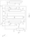
- the HSFCC system 100 generally receives a hydrocarbon feed stream 102 and directly processes the hydrocarbon feed stream 102 to produce one or more system product streams 110.
- the HSFCC system 100 may include a feed separator 104, a first FCC unit 120, a second FCC unit 140, and a regenerator 160.
- the hydrocarbon feed stream 102 may be introduced to the feed separator 104 which may separate the contents of the hydrocarbon feed stream 102 into a greater boiling point fraction stream 106 and a lesser boiling point fraction stream 108.
- the feed separator 104 may be a vapor-liquid separator such as a flash drum (sometimes referred to as a breakpot, knock-out drum, knock-out pot, compressor suction drum, or compressor inlet drum).
- the lesser boiling point fraction stream 108 may exit the feed separator 104 as a vapor and the greater boiling point fraction stream 106 may exit the feed separator 104 as a liquid.
- the vapor-liquid separator may be operated at a temperature suitable to separate the hydrocarbon feed stream 102 into the greater boiling point fraction stream 106 and the lesser boiling point fraction stream 108.
- the temperature of the vapor-liquid separator may be from 180 degrees Celsius (°C) to 400 °C.
- the contents of the lesser boiling point fraction stream 108 may have a boiling point of at least 180 °C and less than or equal to 400 °C, less than or equal to 350 °C, less than or equal to 300 °C, less than or equal to 250 °C, or less than or equal to 200 °C.
- the lesser boiling point fraction stream 108 may have a boiling point of less than 180 °C.
- the contents of the greater boiling point fraction stream 106 may have a boiling point greater than the boiling point of the contents of the lesser boiling point fraction stream 108.
- the contents of the greater boiling point fraction stream 106 may have a boiling point greater than or equal to 200 °C, greater than or equal to 250 °C, greater than or equal to 300 °C, greater than or equal to 350 °C, or greater than or equal to 400 °C.
- the feed separator 104 may be a flashing column that may separate the hydrocarbon feed stream 102 into the greater boiling point fraction stream 106 and the lesser boiling point fraction stream 108.
- the flashing column may be operated at a flashing temperature that results in the greater boiling point fraction stream 106 having less than 10 wt.% Conradson Carbon and less than 10 parts per million by weight (ppmw) total metals.
- the flashing column may be operated at a temperature of from 180 °C to 400 °C.
- the feed separator 104 may include at least one of a distillation device or a cyclonic vapor liquid separation device.
- One or more supplemental feed streams may be added to the hydrocarbon feed stream 102 prior to introducing the hydrocarbon feed stream 102 to the feed separator 104.
- the hydrocarbon feed stream 102 may be crude oil.
- the hydrocarbon feed stream 102 may be crude oil, and one or more supplemental feed streams comprising one or more of a vacuum residue, tar sands, bitumen, atmospheric residue, vacuum gas oils, demetalized oils, naphtha streams, other hydrocarbon streams, or combinations of these materials, may be added to the crude oil upstream of the feed separator 104.
- the hydrocarbon feed stream 102 may alternatively comprise a plurality of refinery hydrocarbon streams outputted from one or more crude oil refinery operations.
- the plurality of refinery hydrocarbon streams may include a vacuum residue, an atmospheric residue, or a vacuum gas oil, for example.
- the plurality of refinery hydrocarbon streams may be combined into the hydrocarbon feed stream 102.
- the hydrocarbon feed stream 102 may be introduced to the feed separator 104 and separated into the greater boiling point fraction stream 106 and the lesser boiling point fraction stream 108.
- the plurality of refinery hydrocarbon streams may be introduced directly to the first FCC unit 120, the second FCC unit 140, or both.
- one or more heavy refinery hydrocarbon streams such as vacuum residues, atmospheric residues, or vacuum gas oils, for example, may be introduced directly to the first FCC unit 120 as the greater boiling point fraction stream 106
- other light refinery hydrocarbon streams such as a naphtha stream for example, may be introduced directly to the second FCC unit 140 as the lesser boiling point fraction stream 108.
- the greater boiling point fraction stream 106 is passed to a first FCC unit 120 that includes a first cracking reaction zone 122.
- the greater boiling point fraction stream 106 is combined or mixed with a first catalyst 124 and cracked to produce a mixture of a spent first catalyst 126 and a first cracking reaction product stream 128.
- Steam 127 may be added to the first cracking reaction zone 122 to further increase the temperature in the first cracking reaction zone 122.
- the spent first catalyst 126 is separated from the first cracking reaction product 128 and passed to a regeneration zone 162 of the regenerator 160.
- the lesser boiling point fraction stream 108 is passed to a second FCC unit 140 that includes a second cracking reaction zone 142.
- the lesser boiling point fraction stream 108 is mixed with a second catalyst 144 and cracked to produce a spent second catalyst 146 and a second cracking reaction product 148.
- Steam 127 may also be added to the second cracking reaction zone 142 to increase the temperature in the second cracking reaction zone 142.
- the spent second catalyst 146 is separated from the second cracking reaction product 148 and passed to the regeneration zone 162 of the regenerator 160.
- the spent first catalyst 126 and the spent second catalyst 146 may be combined and regenerated in the regeneration zone 162 of the regenerator 160 to produce a regenerated catalyst 116.
- the regenerated catalyst 116 may have a catalytic activity that is at least greater than the catalytic activity of the spent first catalyst 126 and the spent second catalyst 146.
- the regenerated catalyst 116 may then be passed back to the first cracking reaction zone 122 and the second cracking reaction zone 142.
- the first cracking reaction zone 122 and the second cracking reaction zone 142 may be operated in parallel.
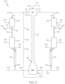
- the HSFCC system 100 includes at least one catalyst recycle, such as spent first catalyst recycle 180, spent second catalyst recycle 182, or both, for example.
- the spent first catalyst 126 may be combined with regenerated catalyst 116 to produce the first catalyst 124 to reduce the temperature, catalytic activity, or both of the first catalyst 124 relative to the regenerated catalyst 116.
- the spent first catalyst 126, spent second catalyst 146, or both may be combined with the regenerated catalyst 116 to reduce the temperature, catalytic activity, or both of the second catalyst 144 relative to the regenerated catalyst 116. Recycling the spent first catalyst 126, the spent second catalyst 146, or both will be discussed in more detail subsequently in this disclosure.
- the first cracking reaction product stream 128 and the second cracking reaction product stream 148 each may include a mixture of cracked hydrocarbon materials, which may be further separated into one or more greater value petrochemical products and recovered from the system in the one or more system product streams 110.
- the first cracking reaction product stream 128, the second cracking reaction product stream 148, or both may include one or more of cracked gas oil, cracked gasoline, cracked naphtha, mixed butenes, butadiene, propene, ethylene, other olefins, ethane, methane, other petrochemical products, or combinations of these.
- the cracked gasoline may be further processed to obtain aromatics such as benzene, toluene, zylenes, or other aromatics for example.
- the HSFCC system 100 may include a product separator 112.
- the first cracking reaction product stream 128, the second cracking reaction product stream 148, or both the first and second cracking reaction product streams 128, 148 may be introduced to the product separator 112 to separate these streams into a plurality of system product streams 110, recycle streams 111, or both system product streams 110 and recycle streams 111.
- the first cracking reaction product stream 128 and the second cracking reaction product stream 148 may be combined into a combined cracking reaction product stream 114.
- the combined cracking reaction product stream 114 may be introduced to the product separator 112.
- the product separator 112 may be fluidly coupled to the first separation zone 130 ( FIG. 2 ), the second separation zone 150 ( FIG. 2 ), or both the first separation zone 130 and the second separation zone 150.
- the first stripped product stream 134 ( FIG. 2 ), the second stripped product stream 154 ( FIG. 2 ), or both may be combined into the combined cracking reaction product stream 114.
- the product separator 112 may be a distillation column that separates the first cracking reaction product stream 128, the second cracking reaction product stream 148, or the combined cracking reaction product stream 114 into one or more system product streams 110, which may include one or more fuel oil streams, gasoline streams, mixed butenes stream, butadiene stream, propene stream, ethylene stream, ethane stream, methane stream, light cycle oil streams (LCO, 216-343 °C), heavy cycle oil streams (HCO, >343 °C), other product streams, or combinations of these.
- Each system product stream 110 may be passed to one or more additional unit operations for further processing.
- the first cracking reaction product stream 128 and the second cracking reaction product stream 148 may be separately introduced to the product separator 112.
- the one or more system product streams 110 may be referred to as petrochemical products, which may be used as intermediates in downstream chemical processing or packaged as finished products.
- the product separator 112 may also produce one or more recycle streams 111, which may be recycled back to the first FCC unit 120, second FCC unit 140, or both the first FCC unit 120 and the second FCC unit 140.
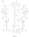
- the first FCC unit 120 may include a first catalyst/feed mixing zone 136, the first cracking reaction zone 122, a first separation zone 130, and a first stripping zone 132.
- the greater boiling point fraction stream 106 may be introduced to the first catalyst/feed mixing zone 136, where the greater boiling point fraction stream 106 may be mixed with the first catalyst 124.
- the first catalyst 124 may include at least the regenerated catalyst 116 that is passed to the first catalyst/feed mixing zone 136 from a catalyst hopper 174.
- the first catalyst 124 may be a mixture of spent first catalyst 126 and regenerated catalyst 116.
- the first catalyst 124 may be a mixture of spent second catalyst 146 and regenerated catalyst 116.
- the catalyst hopper 174 may receive the regenerated catalyst 116 from the regenerator 160.
- the first catalyst 124 may include fresh catalyst (not shown), which is catalyst that has not been circulated through the first FCC unit 120 or the second FCC unit 140 and the regenerator 160. Because the fresh catalyst has not been circulated through a cracking reaction zone, the fresh catalyst may have a catalytic activity that is greater than the regenerated catalyst 116.
- fresh catalyst may also be introduced to the catalyst hopper 174 during operation of the HSFCC system 100 so that a portion of the first catalyst 124 introduced to the first catalyst/feed mixing zone 136 includes the fresh catalyst.
- Fresh catalyst may be introduced to the catalyst hopper 174 periodically during operation to replenish lost catalyst or compensate for spent catalyst that becomes deactivated, such as through heavy metal accumulation in the catalyst.
- one or more supplemental feed streams may be combined with the greater boiling point fraction stream 106 before introduction of the greater boiling point fraction stream 106 to the first catalyst/feed mixing zone 136.
- one or more supplemental feed streams may be added directly to the first catalyst/feed mixing zone 136, where the supplemental feed stream may be mixed with the greater boiling point fraction stream 106 and the first catalyst 124 prior to introduction into the first cracking reaction zone 122.
- the supplemental feed stream may include one or more of vacuum residues, tar sands, bitumen, atmospheric residues, vacuum gas oils, demetalized oils, naphtha streams, other hydrocarbon streams, or combinations of these materials.
- one or more recycle streams 111 ( FIG. 1 ) from the product separator 112 ( FIG. 1 ) may be combined with the greater boiling point fraction stream 106.
- the recycle streams may include a cycle oil or slurry oil recovered from the product separator 112.
- the mixture comprising the greater boiling point fraction stream 106 and the first catalyst 124 may be passed from the first catalyst/feed mixing zone 136 to the first cracking reaction zone 122.
- the mixture of the greater boiling point fraction stream 106 and first catalyst 124 may be introduced to a top portion of the first cracking reaction zone 122.
- the first cracking reaction zone 122 may be a downflow reactor or "downer" reactor in which the reactants flow from the first catalyst/feed mixing zone 136 vertically downward through the first cracking reaction zone 122 to the first separation zone 130.
- Steam 127 may be introduced to the top portion of the first cracking reaction zone 122 to provide additional heating to the mixture of the greater boiling point fraction stream 106 and the first catalyst 124.
- the greater boiling point fraction stream 106 may be reacted by contact with the first catalyst 124 in the first cracking reaction zone 122 to cause at least a portion of the greater boiling point fraction stream 106 to undergo at least a cracking reaction to form at least one cracking reaction product, which may include at least one of the petrochemical products previously described.
- the first catalyst 124 may have a temperature equal to or greater than the first cracking temperature T 122 of the first cracking reaction zone 122 and may transfer heat to the greater boiling point fraction stream 106 to promote the endothermic cracking reaction.
- first cracking reaction zone 122 of the first FCC unit 120 depicted in FIG. 2 is a simplified schematic of one particular embodiment of the first cracking reaction zone 122 of an FCC unit, and other configurations of the first cracking reaction zone 122 may be suitable for incorporation into the HSFCC system 100.
- the first cracking reaction zone 122 may be an up-flow cracking reaction zone.
- Other cracking reaction zone configurations are contemplated.
- the first FCC unit may be a HSFCC unit in which in the first cracking reaction zone 122, the fluidized first catalyst 124 contacts the greater boiling point fraction stream 106 under high-severity conditions.
- the first cracking temperature T 122 of the first cracking reaction zone 122 is 500 °C to 700 from 500 °C to 650 °C, from 500 °C to 600 °C, from 550 °C to 700 °C, from 550 °C to 650 °C, from 550 °C to 600 °C, from 600°C to 700 °C, or from 600 °C to 650 °C.
- the first cracking temperature T 122 of the first cracking reaction zone 122 may be from 500 °C to 700 °C.
- the first cracking temperature T 122 of the first cracking reaction zone 122 may be from 550 °C to 630 °C.
- a weight ratio of the first catalyst 124 to the greater boiling point fraction stream 106 in the first cracking reaction zone 122 may be from 5:1 to 40:1, from 5:1 to 35:1, from 5:1 to 30:1, from 5:1 to 25:1, from 5:1 to 15:1, from 5:1 to 10:1, from 10:1 to 40:1, from 10:1 to 35:1, from 10:1 to 30:1, from 10:1 to 25:1, from 10:1 to 15:1, from 15:1 to 40:1, from 15:1 to 35:1, from 15:1 to 30:1, from 15:1 to 25:1, from 25:1 to 40:1, from 25:1 to 35:1, from 25:1 to 30:1, or from 30:1 to 40:1.
- the residence time of the mixture of first catalyst 124 and the greater boiling point fraction stream 106 in the first cracking reaction zone 122 may be from 0.2 seconds (sec) to 3 sec, from 0.2 sec to 2.5 sec, from 0.2 sec to 2 sec, from 0.2 sec to 1.5 sec, from 0.4 sec to 3 sec, from 0.4 sec to 2.5 sec, or from 0.4 sec to 2 sec, from 0.4 sec to 1.5 sec, from 1.5 sec to 3 sec, from 1.5 sec to 2.5 sec, from 1.5 sec to 2 sec, or from 2 sec to 3 sec.
- the contents of the effluent from the first cracking reaction zone 122 may include the first catalyst 124 and the first cracking reaction product stream 128, which may then be passed to the first separation zone 130.
- the first catalyst 124 may be separated from at least a portion of the first cracking reaction product stream 128.
- the first separation zone 130 may include one or more gas-solid separators, such as one or more cyclones. The first catalyst 124 exiting from the first separation zone 130 may retain at least a residual portion of the first cracking reaction product stream 128.
- the first catalyst 124 which may include the residual portion of the first cracking reaction product 128 retained in the first catalyst 124, may be passed to a first stripping zone 132, where at least some of the residual portion of the first cracking reaction product stream 128 may be stripped from the first catalyst 124 and recovered as a first stripped product stream 134.
- the first stripped product stream 134 may be passed to one or more than one downstream unit operations or combined with one or more than one other streams for further processing.
- Steam 133 may be introduced to the first stripping zone 132 to facilitate stripping the first cracking reaction product 128 from the first catalyst 124.
- the first stripped product stream 134 may include at least a portion of the steam 133 introduced to the first stripping zone 132.
- the first stripped product stream 134 may be discharged from the first stripping zone 132 may be passed through cyclone separators (not shown) and out of the stripper vessel (not shown).
- the first stripped product stream 134 may be directed to one or more product recovery systems in accordance with known methods in the art.
- the first stripped product stream 134 may also be combined with one or more other streams, such as the first cracking reaction product stream 128, for example.
- the spent first catalyst 126 which is the first catalyst 124 after stripping out the first stripped product stream 134, may be passed from the first stripping zone 132 to the regeneration zone 162 of the regenerator 160 to be regenerated to produce regenerated catalyst 116.
- the lesser boiling point fraction stream 108 may be passed from the feed separator 104 ( FIG. 1 ) to the second FCC unit 140.
- the second FCC unit 140 may include a second catalyst/feed mixing zone 156, the second cracking reaction zone 142, a second separation zone 150, and a second stripping zone 152.
- the lesser boiling point fraction stream 108 may be introduced to the second catalyst/feed mixing zone 156, where the lesser boiling point fraction stream 108 may be mixed with the second catalyst 144.
- the second catalyst 144 may include at least the regenerated catalyst 116 that is passed to the second catalyst/feed mixing zone 156 from a catalyst hopper 174.
- the second catalyst 144 may be a mixture of spent second catalyst 146 and regenerated catalyst 116.
- the second catalyst 144 may be a mixture of spent first catalyst 126 and regenerated catalyst 116.
- the catalyst hopper 174 may receive the regenerated catalyst 116 from the regenerator 160 following regeneration of the spent first catalyst 126 and spent second catalyst 146.
- the second catalyst 144 may include fresh catalyst (not shown), which is catalyst that has not been circulated through the first FCC unit 120 or the second FCC unit 140 and the regenerator 160.
- fresh catalyst may also be introduced to catalyst hopper 174 during operation of the HSFCC system 100 so that at least a portion of the second catalyst 144 introduced to the second catalyst/feed mixing zone 156 includes the fresh catalyst.
- Fresh catalyst may be introduced to the catalyst hopper 174 periodically during operation to replenish lost catalyst or compensate for spent catalyst that becomes permanently deactivated, such as through heavy metal accumulation in the catalyst.
- one or more supplemental feed streams may be combined with the lesser boiling point fraction stream 108 before introduction of the lesser boiling point fraction stream 108 to the second catalyst/feed mixing zone 156.
- one or more supplemental feed streams may be added directly to the second catalyst/feed mixing zone 156, where the supplemental feed stream may be mixed with the lesser boiling point fraction stream 108 and the second catalyst 144 prior to introduction into the second cracking reaction zone 142.
- the supplemental feed stream may include one or more naphtha streams or other lesser boiling hydrocarbon streams.
- one or more than one recycle stream 111 ( FIG. 1 ) from the product separator 112 ( FIG. 1 ) may be combined with the lesser boiling point fraction stream 108.
- the mixture comprising the lesser boiling point fraction stream 108 and the second catalyst 144 may be passed from the second catalyst/feed mixing zone 156 to the second cracking reaction zone 142.
- the mixture of the lesser boiling point fraction stream 108 and second catalyst 144 may be introduced to a top portion of the second cracking reaction zone 142.
- the second cracking reaction zone 142 may be a downflow reactor or "downer" reactor in which the reactants flow from the second catalyst/feed mixing zone 156 downward through the second cracking reaction zone 142 to the second separation zone 150.
- Steam 127 may be introduced to the top portion of the second cracking reaction zone 142 to provide additional heating to the mixture of the lesser boiling point fraction stream 108 and the second catalyst 144.
- the lesser boiling point fraction stream 108 may be reacted by contact with the second catalyst 144 in the second cracking reaction zone 142 to cause at least a portion of the lesser boiling point fraction stream 108 to undergo at least one cracking reaction to form at least one cracking reaction product, which may include at least one of the petrochemical products previously described.
- the second catalyst 144 may have a temperature equal to or greater than the second cracking temperature T 142 of the second cracking reaction zone 142 and may transfer heat to the lesser boiling point fraction stream 108 to promote the endothermic cracking reaction.
- the second cracking reaction zone 142 of the second FCC unit 140 depicted in FIG. 2 is a simplified schematic of one particular embodiment of the second cracking reaction zone 142, and other configurations of the second cracking reaction zone 142 may be suitable for incorporation into the HSFCC system 100.
- the second cracking reaction zone 142 may be an up-flow cracking reaction zone.
- Other cracking reaction zone configurations are contemplated.
- the second FCC unit may be an HSFCC unit in which in the second cracking reaction zone 142, the fluidized second catalyst 144 contacts the lesser boiling point fraction stream 108 at high-severity conditions.
- the second cracking temperature T 142 of the second cracking reaction zone 142 is from 500 °C to 700 °C, from 500 °C to 650 °C, from 500 °C to 600 °C, from 550 °C to 700 °C, from 550 °C to 650 °C, from 550 °C to 600 °C, from 600 °C to 700 °C, or from 600 °C to 650 °C.
- the second cracking temperature T 142 of the second cracking reaction zone 142 may be from 550 °C to 630 °C.
- the second cracking temperature T 142 may be different than the first cracking temperature T 122 .
- a weight ratio of the second catalyst 144 to the lesser boiling point fraction stream 108 in the second cracking reaction zone 142 may be from 5:1 to 40:1, from 5:1 to 35:1, from 5:1 to 30:1, from 5:1 to 25:1, from 5:1 to 15:1, from 5:1 to 10:1, from 10:1 to 40:1, from 10:1 to 35:1, from 10:1 to 30:1, from 10:1 to 25:1, from 10:1 to 15:1, from 15:1 to 40:1, from 15:1 to 35:1, from 15:1 to 30:1, from 15:1 to 25:1, from 25:1 to 40:1, from 25:1 to 35:1, from 25:1 to 30:1, or from 30:1 to 40:1.
- the weight ratio of the second catalyst 144 to the lesser boiling point fraction stream 108 in the second cracking reaction zone 142 may be different than the weight ratio of the first catalyst 124 to the greater boiling point fraction stream 106 in the first cracking reaction zone 122.
- the residence time of the mixture of second catalyst 144 and the lesser boiling point fraction stream 108 in the second cracking reaction zone 142 may be from 0.2 seconds (sec) to 3 sec, from 0.2 sec to 2.5 sec, from 0.2 sec to 2 sec, from 0.2 sec to 1.5 sec, from 0.4 sec to 3 sec, from 0.4 sec to 2.5 sec, or from 0.4 sec to 2 sec, from 0.4 sec to 1.5 sec, from 1.5 sec to 3 sec, from 1.5 sec to 2.5 sec, from 1.5 sec to 2 sec, or from 2 sec to 3 sec.
- the residence time in the second cracking reaction zone 142 may be different than the residence time in the first cracking reaction zone 122.
- the contents of effluent from the second cracking reaction zone 142 may include second catalyst 144 and the second cracking reaction product stream 148, which may be passed to the second separation zone 150.
- the second catalyst 144 may be separated from at least a portion of the second cracking reaction product stream 148.
- the second separation zone 150 may include one or more gas-solid separators, such as one or more cyclones. The second catalyst 144 exiting from the second separation zone 150 may retain at least a residual portion of the second cracking reaction product stream 148.
- the second catalyst 144 may be passed to the second stripping zone 152, where at least some of the residual portion of the second cracking reaction product stream 148 may be stripped from the second catalyst 144 and recovered as a second stripped product stream 154.
- the second stripped product stream 154 may be passed to one or more than one downstream unit operations or combined with one or more than one other streams for further processing.
- Steam 133 may be introduced to the second stripping zone 152 to facilitate stripping the second cracking reaction product 148 from the second catalyst 144.
- the second stripped product stream 154 may include at least a portion of the steam 133 introduced to the second stripping zone 152 and may be passed out of the second stripping zone 152.
- the second stripped product stream 154 may pass through cyclone separators (not shown) and out of the stripper vessel (not shown).
- the second stripped product stream 154 may be directed to one or more product recovery systems in accordance with known methods in the art.
- the second stripped product stream 154 may also be combined with one or more other streams, such as the second cracking reaction product stream 148. Combination with other streams is contemplated.
- the spent second catalyst 146 which is the second catalyst 144 after stripping out the second stripped product stream 154, may be passed from the second stripping zone 152 to the regeneration zone 162 of the regenerator 160.
- the catalyst used in the HSFCC system 100 may include one or more fluid catalytic cracking catalysts that are suitable for use in the first cracking reaction zone 122 and the second cracking reaction zone 142.
- the catalyst may be a heat carrier and may provide heat transfer to the greater boiling point fraction stream 106 in the first cracking reaction zone 122 operated at high-severity conditions and the lesser boiling point fraction 108 in the second cracking reaction zone 142 operated at high-severity conditions.
- the catalyst may also have a plurality of catalytically active sites, such as acidic sites for example, that promote the cracking reaction.
- the catalyst may be a high-activity FCC catalyst having high catalytic activity.
- fluid catalytic cracking catalysts suitable for use in the HSFCC system 100 may include, without limitation, zeolites, silica-alumina catalysts, carbon monoxide burning promoter additives, bottoms cracking additives, light olefin-producing additives, other catalyst additives, or combinations of these components.
- Zeolites that may be used as at least a portion of the catalyst for cracking may include, but are not limited to Y, REY, USY, RE-USY zeolites, or combinations of these.
- the catalyst may also include a shaped selective catalyst additive, such as ZSM-5 zeolite crystals or other pentasil-type catalyst structures, which are often used in other FCC processes to produce light olefins and/or increase FCC gasoline octane.
- the catalyst may include a mixture of a ZSM-5 zeolite crystals and the cracking catalyst zeolite and matrix structure of a typical FCC cracking catalyst.
- the catalyst may be a mixture of Y and ZSM-5 zeolite catalysts embedded with clay, alumina, and binder.
- At least a portion of the catalyst may be modified to include one or more rare earth elements (15 elements of the Lanthanide series of the IUPAC Periodic Table plus scandium and yttrium), alkaline earth metals (Group 2 of the IUPAC Periodic Table), transition metals, phosphorus, fluorine, or any combination of these, which may enhance olefin yield in the first cracking reaction zone 122, second cracking reaction zone 142, or both.
- Transition metals may include "an element whose atom has a partially filled d sub-shell, or which can give rise to cations with an incomplete d sub-shell" [IUPAC, Compendium of Chemical Terminology, 2nd ed. (the "Gold Book”) (1997).
- transition metals or metal oxides may also be impregnated onto the catalyst.
- Metals or metal oxides may include one or more metals from Groups 6-10 of the IUPAC Periodic Table.
- the metals or metal oxides may include one or more of molybdenum, rhenium, tungsten, or any combination of these.
- a portion of the catalyst may be impregnated with tungsten oxide.
- the first FCC unit 120 and the second FCC unit 140 share the regenerator 160.
- the spent first catalyst 126 and the spent second catalyst 146 may be passed to the regenerator 160, where the spent first catalyst 126 and the spent second catalyst 146 are mixed together and regenerated to produce the regenerated catalyst 116.
- the regenerator 160 may include the regeneration zone 162, a catalyst transfer line 164, the catalyst hopper 174, and a flue gas vent 166.
- the catalyst transfer line 164 is fluidly coupled to the regeneration zone 162 and the catalyst hopper 174 for passing the regenerated catalyst 116 from the regeneration zone 162 to the catalyst hopper 174.
- the regenerator 160 may have more than one catalyst hopper 174, such as a first catalyst hopper (not shown) for the first FCC unit 120 and a second catalyst hopper (not shown) for the second FCC unit 140, for example.
- the flue gas vent 166 may be positioned at the catalyst hopper 174.
- the spent first catalyst 126 and spent second catalyst 146 may be passed from the first stripping zone 132 and the second stripping zone 152, respectively, to the regeneration zone 162.
- Combustion gas 170 may be introduced to the regeneration zone 162.
- the combustion gases 170 may include one or more of combustion air, oxygen, fuel gas, fuel oil, other component, or any combinations of these.
- the coke deposited on the spent first catalyst 126 and the spent second catalyst 146 may at least partially oxidize (combusts) in the presence of the combustion gases 170 to form at least carbon dioxide and water.
- the coke deposits on the spent first catalyst 126 and spent second catalyst 146 may be fully oxidized in the regeneration zone 162.
- organic compounds such as residual first cracking reaction product or second cracking reaction product for example, may also oxidize in the presence of the combustion gases 170 in the regeneration zone.
- gases such as carbon monoxide for example, may be formed during coke oxidation in the regeneration zone 162. Oxidation of the coke deposits produces heat, which may be transferred to and retained by the regenerated catalyst 116.
- the single catalyst regenerator 160 for regenerating the spent first catalyst 126 and the spent second catalyst 146 may improve the overall efficiency of the HSFCC system 100. For example, cracking of the lesser boiling point fraction 108 in the second FCC unit 140 may produce less coke deposits on the spent second catalyst 146 compared to cracking of the greater boiling point fraction 106 in the first FCC unit. Combustion of the coke deposits on the spent second catalyst 146 during regeneration produces heat, but the amount of coke present on the spent second catalyst 146 may not be sufficient to produce enough heat to conduct the cracking reactions in the second cracking reaction zone 142.
- regeneration of the spent second catalyst 146 by itself may not produce enough heat to raise the temperature of the regenerated catalyst 116 to an acceptable second cracking temperature T 142 in the second cracking reaction zone 142.
- the amount of coke formed and deposited on the spent first catalyst 126 during cracking of the greater boiling point fraction stream 106 in the first FCC unit 120 may be substantially greater than the coke deposits produced in the second cracking reaction zone 142.
- Combustion of the coke deposits on the spent first catalyst 126 during catalyst regeneration may produce sufficient heat to raise the temperature of the regenerated catalyst 116 (including regenerated catalyst 116 produced from both the spent first catalyst 126 and the spent second catalyst 146) to high-severity conditions, such as a regenerated catalyst temperature T 116 equal to or greater than the first cracking temperature T 122 or the second cracking temperature T 142 for example, and may provide the heat required to conduct the cracking reactions in both the first cracking reaction zone 122 and the second cracking reaction zone 142.
- the flue gases 172 may convey the regenerated catalyst 116 through the catalyst transfer line 164 from the regeneration zone 162 to the catalyst hopper 174.
- the regenerated catalyst 116 may accumulate in the catalyst hopper 174 prior to passing from the catalyst hopper 174 to the first FCC unit 120 and the second FCC unit 140.
- the catalyst hopper 174 may act as a gas-solid separator to separate the flue gas 172 from the regenerated catalyst 116.
- the flue gas 172 may pass out of the catalyst hopper 174 through a flue gas vent 166 disposed in the catalyst hopper 174.
- the catalyst may be circulated through the first and second FCC units 120, 140, the regenerator 160, and the catalyst hopper 174.
- the first catalyst 124 may be introduced to the first FCC unit 120 to catalytically crack the greater boiling point fraction 106 in the first FCC unit 120.
- coke deposits may form on the first catalyst 124 to produce the spent first catalyst 126 passing out of the first stripping zone 132.
- the spent first catalyst 126 may have catalytic activity that is less than the regenerated catalyst 116, meaning that the spent first catalyst 126 may be less effective at enabling cracking reactions compared to the regenerated catalyst 116.
- the spent first catalyst 126 may be separated from the first cracking reaction product stream 128 in the first separation zone 130 and the first stripping zone 132.
- the second catalyst 144 may be introduced to the second FCC unit 140 to catalytically crack the lesser boiling point fraction 108 in the second FCC unit 140. During cracking, coke deposits may form on the second catalyst 144 to produce the spent second catalyst 146 passing out of the second stripping zone 152.
- the spent second catalyst 146 also may have a catalytic activity that is less than the catalytic activity of the regenerated catalyst 116, meaning that the spent second catalyst 146 may be less effective at enabling the cracking reactions compared to the regenerated catalyst 116.
- the spent second catalyst 146 may be separated from the second cracking reaction product stream 148 in the second separation zone 150 and the second stripping zone 152.
- the spent first catalyst 126 and spent second catalyst 146 may then be combined and regenerated in the regeneration zone 162 to produce the regenerated catalyst 116.
- the regenerated catalyst 116 may be transferred to the catalyst hopper 174.
- the regenerated catalyst 116 passing out of the regeneration zone 162 may have less than 1 wt. % coke deposits, based on the total weight of the regenerated catalyst 116. In some embodiments, the regenerated catalyst 116 passing out of the regeneration zone 162 may have less than 0.5 wt. %, less than 0.1 wt. %, or less than 0.05 wt.% coke deposits.
- the regenerated catalyst 116 passing out of the regeneration zone 162 to the catalyst hopper 174 may have from 0.001 wt.% to 1 wt.%, from 0.001 wt.% to 0.5 wt.%, from 0.001 wt.% to 0.1 wt.%, from 0.001 wt.% to 0.05 wt.%, from 0.005 wt.% to 1 wt.%, from 0.005 wt.% to 0.5 wt.%, from 0.005 wt.% to 0.1 wt.%, from 0.005 wt.% to 0.05 wt.%, from 0.01 wt.% to 1 wt.%, from 0.01 wt.% to 0.5 wt.% to 0.01 wt.% to 0.1 wt.%, from 0.01 wt.% to 0.05 wt.% coke deposits, based on the total weight of the regenerated catalyst 116.
- the regenerated catalyst 116 passing out of regeneration zone 162 may be substantially free of coke deposits.
- the term "substantially free" of a component means less than 1 wt. % of that component in a particular portion of a catalyst, stream, or reaction zone.
- the regenerated catalyst 116 that is substantially free of coke deposits may have less than 1 wt. % of coke deposits. Removal of the coke deposits from the regenerated catalyst 116 in the regeneration zone 162 may remove the coke deposits from the catalytically active sites, such as acidic sites for example, of the catalyst that promote the cracking reaction.
- Removal of the coke deposits from the catalytically active sites on the catalyst may increase the catalytic activity of the regenerated catalyst 116 compared to the spent first catalyst 126 and spent second catalyst 146.
- the regenerated catalyst 116 may have a catalytic activity that is greater than the spent first catalyst 126 and the spent second catalyst 146.
- the regenerated catalyst 116 may absorb at least a portion of the heat generated from combustion of the coke deposits. The heat may increase the temperature of the regenerated catalyst 116 compared to the temperature of the spent first catalyst 126 and spent second catalyst 146. The regenerated catalyst 116 may accumulate in the catalyst hopper 174 until it is passed back to the first FCC unit 120 as at least a portion of the first catalyst 124 and the second FCC unit 140 as at least a portion of the second catalyst 144.
- the regenerated catalyst 116 in the catalyst hopper 174 may have a temperature that is equal to or greater than the first cracking temperature T 122 in the first cracking reaction zone 122 of the first FCC unit 120, the second cracking temperature T 142 in the second cracking reaction zone 142 of the second FCC unit 140, or both.
- the greater temperature of the regenerated catalyst 116 may provide heat for the endothermic cracking reaction in the first cracking reaction zone 122, the second cracking reaction zone 142, or both.
- hydrocarbon feed streams 102 such as crude oil for example, can have a wide range of compositions and a wide range of boiling points.
- the hydrocarbon feed stream 102 may be separated into the greater boiling point fraction 106 and the lesser boiling point fraction 108.
- the greater boiling point fraction 106 generally has a different composition than the lesser boiling point fraction 108.
- each of the greater boiling point fraction 106 and the lesser boiling point fraction 108 may require different operating temperatures and catalyst activities to produce desired yields of one or more petrochemical products or increase the selectivity of the reaction for certain products.
- the greater boiling point fraction 106 may be more reactive and, thus, may require less cracking activity than the lesser boiling point fraction 108 to produce sufficient yields of or selectivity for a specific petrochemical product.
- the lesser cracking activity suitable for the greater boiling point fraction 106 may be provided by reducing the catalytic activity of the first catalyst 124 in the first cracking reaction zone 122, reducing the first cracking temperature T 122 in the first cracking reaction zone 122, or a combination of both.
- the lesser boiling point fraction 108 may be less reactive and may require greater catalytic activity, such as an increased catalytic activity of the second catalyst 144 in the second cracking reaction zone 142, a second cracking temperature T 142 in the second cracking reaction zone 142 greater than the first cracking temperature T 122 , or both, compared to the greater boiling point fraction 106 to produce sufficient yields of or selectivity for the specific petrochemical products.
- the HSFCC system 100 may include a single regenerator 160 to regenerate the spent first catalyst 126 and the spent second catalyst 146 to produce the regenerated catalyst 116. Therefore, the regenerated catalyst 116 passed to the first FCC unit 120 is the same as and has the same catalytic effectiveness and temperature as the regenerated catalyst 116 passed to the second FCC unit 140.
- the reaction conditions in the first FCC unit 120 or second FCC unit 140 for producing sufficient yields of or selectivity for specific petrochemical products may be different than the reaction conditions provided by passing the regenerated catalyst 116 to the other of the first FCC unit 120 or the second FCC unit 140.
- a portion of the spent first catalyst 126, a portion of the spent second catalyst 146, or both may be recycled to the first FCC unit 120, the second FCC unit 140, or both.
- the recycle portion 190 ( FIG. 2 ) of the spent first catalyst 126, the recycle portion 194 ( FIG. 3 ) of the spent second catalyst 146, or both may bypass the regenerator 160 so that the recycle portion 190 of the spent first catalyst 126, the recycle portion 194 of the spent second catalyst 146, or both may be introduced back into the first FCC unit 120, the second FCC unit 140, or both without being regenerated.
- a spent first catalyst temperature T 126 of the recycle portion 190 of the spent first catalyst 126, the spent second catalyst temperature T 146 of the recycle portion 194 of the spent second catalyst 146, or both may be less than the regenerated catalyst temperature T 116 . Additionally, the recycle portion 190 of the spent first catalyst 126, the recycle portion 194 of the spent second catalyst 146, or both may have reduced catalytic effectiveness compared to the regenerated catalyst 116.
- Recycling a portion of the spent first catalyst 126 or spent second catalyst 146 back to the first FCC unit 120, the second FCC unit 140, or both may reduce the first cracking temperature T 122 in the first cracking reaction zone 122 or the second cracking temperature T 142 in the second cracking reaction zone, or both. Recycling a portion of the spent first catalyst 126 or the spent second catalyst 146 back to the first FCC unit 120, the second FCC unit 140, or both may also reduce the average catalytic activity of the first catalyst 124 in the first cracking reaction zone 122, the second catalyst 144 in the second cracking reaction zone 142, or both.
- the HSFCC system 100 may include a spent first catalyst recycle 180.
- the spent first catalyst recycle 180 may fluidly couple an outlet 135 of the first stripping zone 132 to an inlet 137 of the first catalyst/feed mixing zone 136.
- the spent first catalyst recycle 180 may pass the recycle portion 190 of the spent first catalyst 126 from the outlet 135 of the first stripping zone 132 to the inlet 137 of the first catalyst/feed mixing zone 136.
- the recycle portion 190 of the spent first catalyst 126 may be combined with regenerated catalyst 116 from the catalyst hopper 174 upstream of the first cracking reaction zone 122 such that the first catalyst 124 introduced to the first cracking reaction zone 122 comprises a mixture of the regenerated catalyst 116 and the recycle portion 190 of the spent first catalyst 126.
- the recycle portion 190 of the spent first catalyst 126 may be introduced to the first catalyst/feed mixing zone 136 where the recycle portion 190 of the spent first catalyst 126 is mixed with the regenerated catalyst 116 and the greater boiling point fraction stream 106 before passing the first catalyst 124 (mixture of the spent first catalyst 126 and regenerated catalyst 116) and the greater boiling point fraction stream 106 to the first cracking reaction zone 122.
- the recycle portion 190 of the spent first catalyst 126 may be combined with the regenerated catalyst 116 upstream of the first catalyst/feed mixing zone 136.
- a non-recycle portion 192 of the spent first catalyst 126 may be passed to the regenerator 160 for regeneration.
- the recycle portion 190 of the spent first catalyst 126 may have a spent first catalyst temperature T 126 that is less than a regenerated catalyst temperature T 116 of the regenerated catalyst 116. Mixing of the recycle portion 190 of the spent first catalyst 126 with the regenerated catalyst 116 may reduce the average temperature of the first catalyst 124 introduced to the first cracking reaction zone 122. Reducing the average temperature of the first catalyst 124 may reduce the first cracking temperature T 122 in the first cracking reaction zone 122.
- mixing the recycle portion 190 of the spent first catalyst 126 with the regenerated catalyst 116 may reduce the average catalytic activity of the first catalyst 124 introduced to the first cracking reaction zone 122.
- coke deposits may form on the spent first catalyst 126.
- the coke deposits may block catalytically active sites on the spent first catalyst 126 reducing the catalytic activity of the spent first catalyst 126.
- the spent first catalyst 126 may have lesser catalytic activity compared to the regenerated catalyst 116.
- mixing the recycle portion 190 of the spent first catalyst 126 with the regenerated catalyst 116 to produce the first catalyst 124 may reduce the average catalytic activity of the first catalyst 124 introduced to the first cracking reaction zone 122 compared to the catalytic activity of the regenerated catalyst 116.
- the first catalyst 124 introduced to the first cracking reaction zone 122 may have a weight ratio of the spent first catalyst 126 to the regenerated catalyst 116 sufficient to reduce the first cracking temperature T 122 in the first cracking reaction zone 122 compared to the regenerated catalyst temperature T 116 . In other embodiments, the first catalyst 124 introduced to the first cracking reaction zone 122 may have a weight ratio of the spent first catalyst 126 to the regenerated catalyst 116 sufficient to reduce the average catalytic activity of the first catalyst 124 introduced to the first cracking reaction zone 122 compared to the catalytic activity of the regenerated catalyst 116.
- the first catalyst 124 may have a weight ratio of the spent first catalyst 126 to the regenerated catalyst 116 sufficient to increase the yield of a petrochemical product in the first cracking reaction product stream 128 compared to the yield of the same petrochemical product attainable by feeding the regenerated catalyst 116 to the first cracking reaction zone 122 without the spent first catalyst 126.
- the first catalyst 124 introduced to the first cracking reaction zone 122 may have a weight ratio of the spent first catalyst 126 to the regenerated catalyst 116 of from 1:99 to 99:1, from 1:99 to 90:10, from 1:99 to 75:25, from 1:99 to 50:50, from 1:99 to 25:75, from 1:99 to 10:90, from 10:90 to 99:1, from 10:90 to 90:10, from 10:90 to 75:25, from 10:90 to 50:50, from 10:90 to 25:75, from 25:75 to 99:1, from 25:75 to 90:10, from 25:75 to 75:25, from 25:75 to 50:50, from 50:50 to 99:1, from 50:50 to 90:10, from 50:50 to 75:25, from 75:25 to 99:1, from 75:25 to 90:10, or from 90:10 to 99:1.
- the weight ratio of the spent first catalyst 126 to the regenerated catalyst 116 in the first catalyst 124 introduced to the first cracking reaction zone 122 may be controlled to modify the reaction conditions in the first cracking reaction zone 122.
- controlling the weight ratio of the spent first catalyst 126 to the regenerated catalyst 116 in the first catalyst 124 introduced to the first cracking reaction zone 122 may control the first cracking temperature T 122 , an average catalyst activity, or both in the first cracking reaction zone 122, which may enable improving the yield of one or more petrochemical products in the first cracking reaction product stream 128.
- the weight ratio of the spent first catalyst 126 to the regenerated catalyst 116 may be controlled by controlling the flow rate of the recycle portion 190 of the spent first catalyst 126 through the spent first catalyst recycle 180, the flow rate of regenerated catalyst 116 from the catalyst hopper 174, or both.
- increasing the weight ratio of the spent first catalyst 126 to the regenerated catalyst 116 in the first catalyst 124 introduced to the first cracking reaction zone 122 may increase the yield of olefins, such as butene, propene, and other olefins for example, and may decrease the yield of gasolines.
- decreasing the weight ratio of the spent first catalyst 126 to the regenerated catalyst 116 in the first catalyst 124 introduced to the first cracking reaction zone 122 may increase the yield of gasolines, and decrease the yield of olefins, such as butene, propene, and other olefins for example.
- the weight ratio of the spent first catalyst 126 to the regenerated catalyst 116 in the first catalyst 124 introduced to the first cracking reaction zone 122 or the recycle rate of the spent first catalyst 126 may be controlled in response to the catalyst to hydrocarbon weight ratio in the first cracking reaction zone 122.
- the weight ratio of the spent first catalyst 126 to the regenerated catalyst 116 in the first catalyst 124 introduced to the first cracking reaction zone 122 or the recycle rate of the spent first catalyst 126 may be controlled in response to the product selectivity of the first cracking reaction zone 122, which may be determined by measuring the composition of the first cracking reaction product stream 128.
- the HSFCC system 100 may include a spent second catalyst recycle 182.
- the spent second catalyst recycle 182 may fluidly couple an outlet 155 of the second stripping zone 152 to an inlet 157 of the second catalyst/feed mixing zone 156.
- the spent second catalyst recycle 182 may pass the recycle portion 194 of the spent second catalyst 146 from the outlet 155 of the second stripping zone 152 to the inlet 157 of the second catalyst/feed mixing zone 156.
- the recycle portion 194 of the spent second catalyst 146 may be combined with regenerated catalyst 116 from the catalyst hopper 174 upstream of the second cracking reaction zone 142 such that the second catalyst 144 introduced to the second cracking reaction zone 142 comprises a mixture of the regenerated catalyst 116 and the recycle portion 194 of the spent second catalyst 146.
- the recycle portion 194 of the spent second catalyst 146 may be introduced to the second catalyst/feed mixing zone 156 where the recycle portion 194 of the spent second catalyst 146 is mixed with the regenerated catalyst 116 and the lesser boiling point fraction stream 108 before passing the second catalyst 144 (mixture of the spent second catalyst 146 and the regenerated catalyst 116) and the lesser boiling point fraction stream 108 to the second cracking reaction zone 142.
- the recycle portion 194 of the spent second catalyst 146 may be combined with the regenerated catalyst 116 upstream of the second catalyst/feed mixing zone 156.
- a non-recycle portion 196 of the spent second catalyst 146 may be passed to the regenerator 160 for regeneration.
- the recycle portion 194 of the spent second catalyst 146 may have a spent second catalyst temperature T 146 that may be less than the regenerated catalyst temperature T 116 of the regenerated catalyst 116. Mixing the recycle portion 194 of the spent second catalyst 146 with the regenerated catalyst 116 may reduce the average temperature of the second catalyst 144 introduced to the second cracking reaction zone 142. Reducing the average temperature of the second catalyst 144 may reduce the second cracking temperature T 142 in the second cracking reaction zone 142.
- mixing the recycle portion 194 of the spent second catalyst 146 with the regenerated catalyst 116 may reduce the average catalytic activity of the second catalyst 144 introduced to the second cracking reaction zone 142.
- coke deposits may form on the spent second catalyst 146.
- the coke deposits may block catalytically active sites on the spent second catalyst 146 reducing the catalytic effectiveness of the spent second catalyst 146.
- the spent second catalyst 146 may have lesser catalytic effectiveness compared to the regenerated catalyst 116.
- mixing the recycle portion 194 of the spent second catalyst 146 with the regenerated catalyst 116 to provide the second catalyst 144 for the second cracking reaction zone 142 may reduce the average catalytic activity of the second catalyst 144 introduced to the second cracking reaction zone 142 compared to the catalytic activity of the regenerated catalyst 116.
- the second catalyst 144 introduced to the second cracking reaction zone 142 may have a weight ratio of the spent second catalyst 146 to the regenerated catalyst 116 sufficient to reduce the second cracking temperature T 142 in the second cracking reaction zone 142 compared to the regenerated catalyst temperature T 116 .
- the second catalyst 144 introduced to the second cracking reaction zone 142 may have a weight ratio of the spent second catalyst 146 to the regenerated catalyst 116 sufficient to reduce the average catalytic activity of the second catalyst 144 introduced to the second cracking reaction zone 142 compared to the catalytic activity of the regenerated catalyst 116.
- the second catalyst 144 may have a weight ratio of the spent second catalyst 146 to the regenerated catalyst 116 sufficient to increase the yield of a petrochemical product in the second cracking reaction product stream 148 compared to the yield of the same petrochemical product attainable by feeding the regenerated catalyst 116 to the second cracking reaction zone 142 without the spent second catalyst 146.
- the second catalyst 144 introduced to the second cracking reaction zone 142 may have a weight ratio of the spent second catalyst 146 to the regenerated catalyst 116 of from 1:99 to 99:1, from 1:99 to 90:10, from 1:99 to 75:25, from 1:99 to 50:50, from 1:99 to 25:75, from 1:99 to 10:90, from 10:90 to 99:1, from 10:90 to 90:10, from 10:90 to 75:25, from 10:90 to 50:50, from 10:90 to 25:75, from 25:75 to 99:1, from 25:75 to 90:10, from 25:75 to 75:25, from 25:75 to 50:50, from 50:50 to 99:1, from 50:50 to 90:10, from 50:50 to 75:25, from 75:25 to 99:1, from 75:25 to 90:10, or from 90:10 to 99:1.
- the weight ratio of the spent second catalyst 146 to the regenerated catalyst 116 in the second catalyst 144 introduced to the second cracking reaction zone 142 may be controlled to modify the reaction conditions in the second cracking reaction zone 142.
- controlling the weight ratio of the spent second catalyst 146 to the regenerated catalyst 116 in the second catalyst 144 may control the second cracking temperature T 142 , an average catalyst activity, or both in the second cracking reaction zone 142, which may enable increasing the yield of one or more petrochemical products in the second cracking reaction product stream 148.
- the weight ratio of the spent second catalyst 146 to the regenerated catalyst 116 may be controlled by controlling the flow rate of the recycle portion 194 of the spent second catalyst 146 through the spent second catalyst recycle 182, the flow rate of regenerated catalyst 116 from the catalyst hopper 174, or both.
- increasing the weight ratio of the spent second catalyst 146 to the regenerated catalyst 116 in the second catalyst 144 introduced to the second cracking reaction zone 142 may increase the yield of olefins, such as butene, propene, and other olefins for example, and may decrease the yield of gasolines.
- decreasing the weight ratio of the spent second catalyst 146 to the regenerated catalyst 116 in the second catalyst 144 introduced to the second cracking reaction zone 142 may increase the yield of gasolines, and decrease the yield of olefins, such as butene, propene, and other olefins for example.
- the weight ratio of the spent second catalyst 146 to the regenerated catalyst 116 in the second catalyst 144 introduced to the second cracking reaction zone 142 or the recycle rate of the spent second catalyst 146 may be controlled in response to the catalyst to hydrocarbon weight ratio in the second cracking reaction zone 142.
- the weight ratio of the spent second catalyst 146 to the regenerated catalyst 116 in the second catalyst 144 introduced to the second cracking reaction zone 142 or the recycle rate of the spent second catalyst 146 may be controlled in response to the product selectivity of the second cracking reaction zone 142, which may be determined by measuring the composition of the second cracking reaction product stream 148.
- the HSFCC system 100 may be configured to recycle the recycle portion 190 of the spent first catalyst 126 from the first stripping zone 132 to the second FCC unit 140.
- the HSFCC system 100 may include a spent first catalyst cross-recycle 184 fluidly coupling the outlet 135 of the first stripping zone 132 to the inlet 157 of the second catalyst/feed mixing zone 156.
- the spent first catalyst cross-recycle 184 may pass the recycle portion 190 of the spent first catalyst 126 from the outlet 135 of the first stripping zone 132 to the inlet 157 of the first catalyst/feed mixing zone 136.
- the recycle portion 190 of the spent first catalyst 126 may be combined with regenerated catalyst 116 from the catalyst hopper 174 upstream of the second cracking reaction zone 142 such that the second catalyst 144 introduced to the second cracking reaction zone 142 comprises a mixture of the regenerated catalyst 116 and the recycle portion 190 of the spent first catalyst 126.
- the recycle portion 190 of the spent first catalyst 126 may be introduced to the second catalyst/feed mixing zone 156 where the recycle portion 190 of the spent first catalyst 126 is mixed with the regenerated catalyst 116 and the lesser boiling point fraction stream 108 before passing the second catalyst 144 (mixture of the spent first catalyst 126 and regenerated catalyst 116) and the lesser boiling point fraction stream 108 to the second cracking reaction zone 142.
- the recycle portion 190 of the spent first catalyst 126 may be combined with the regenerated catalyst 116 upstream of the second catalyst/feed mixing zone 156.
- the non-recycle portion 192 of the spent first catalyst 126 may be passed to the regenerator 160 for regeneration.
- the recycle portion 190 of the spent first catalyst 126 may have a spent first catalyst temperature T 126 that is less than the regenerated catalyst temperature T 116 of the regenerated catalyst 116. Mixing of the recycle portion 190 of the spent first catalyst 126 with the regenerated catalyst 116 may reduce the average temperature of the second catalyst 144 introduced to the second cracking reaction zone 142. Reducing the average temperature of the second catalyst 144 may reduce the second cracking temperature T 142 in the second cracking reaction zone 142.
- mixing the recycle portion 190 of the spent first catalyst 126 with the regenerated catalyst 116 may reduce the average catalytic activity of the second catalyst 144 introduced to the second cracking reaction zone 142.
- coke deposits may form on the spent first catalyst 126.
- the coke deposits may block catalytically active sites on the spent first catalyst 126 reducing the catalytic effectiveness of the spent first catalyst 126.
- the spent first catalyst 126 may have lesser catalytic effectiveness compared to the regenerated catalyst 116.
- mixing the recycle portion 190 of the spent first catalyst 126 with the regenerated catalyst 116 to produce the second catalyst 144 may reduce the average catalytic activity of the second catalyst 144 introduced to the second cracking reaction zone 142 compared to the catalytic activity of the regenerated catalyst 116.
- the second catalyst 144 introduced to the second cracking reaction zone 142 may have a weight ratio of the spent first catalyst 126 to the regenerated catalyst 116 sufficient to reduce the second cracking temperature T 142 in the second cracking reaction zone 142 compared to the regenerated catalyst temperature T 116 .
- the second catalyst 144 introduced to the second cracking reaction zone 142 may have a weight ratio of the spent first catalyst 126 to the regenerated catalyst 116 sufficient to reduce the average catalytic activity of the second catalyst 144 introduced to the second cracking reaction zone 142 compared to the catalytic activity of the regenerated catalyst 116.
- the second catalyst 144 may have a weight ratio of the spent first catalyst 126 to the regenerated catalyst 116 sufficient to increase the yield of a petrochemical product in the second cracking reaction product stream 148 compared to the yield of the same petrochemical product attainable by feeding the regenerated catalyst 116 to the second cracking reaction zone 142 without the spent first catalyst 126.
- the second catalyst 144 introduced to the second cracking reaction zone 142 may have a weight ratio of the spent first catalyst 126 to the regenerated catalyst 116 of from 1:99 to 99:1, from 1:99 to 90:10, from 1:99 to 75:25, from 1:99 to 50:50, from 1:99 to 25:75, from 1:99 to 10:90, from 10:90 to 99:1, from 10:90 to 90:10, from 10:90 to 75:25, from 10:90 to 50:50, from 10:90 to 25:75, from 25:75 to 99:1, from 25:75 to 90:10, from 25:75 to 75:25, from 25:75 to 50:50, from 50:50 to 99:1, from 50:50 to 90:10, from 50:50 to 75:25, from 75:25 to 99:1, from 75:25 to 90:10, or from 90:10 to 99:1.
- the weight ratio of the spent first catalyst 126 to the regenerated catalyst 116 in the second catalyst 144 introduced to the second cracking reaction zone 142 may be controlled to modify the reaction conditions in the second cracking reaction zone 142.
- controlling the weight ratio of the spent first catalyst 126 to the regenerated catalyst 116 in the second catalyst 144 may control the second cracking temperature T 142 , an average catalyst activity, or both in the second cracking reaction zone 142, which may enable improving the yield of one or more petrochemical products in the second cracking reaction product stream 148.
- the weight ratio of the spent first catalyst 126 to the regenerated catalyst 116 may be controlled by controlling the flow rate of the recycle portion 190 of the spent first catalyst 126 through the spent first catalyst cross-recycle 184, the flow rate of regenerated catalyst 116 from the catalyst hopper 174, or both.
- increasing the weight ratio of the spent first catalyst 126 to the regenerated catalyst 116 in the second catalyst 144 introduced to the second cracking reaction zone 142 may increase the yield of olefins, such as butene, propene, and other olefins for example, and may decrease the yield of gasolines in the second cracking reaction product stream 148.
- decreasing the weight ratio of the spent first catalyst 126 to the regenerated catalyst 116 in the second catalyst 144 introduced to the second cracking reaction zone 142 may increase the yield of gasolines, and decrease the yield of olefins, such as butene, propene, and other olefins for example, in the second cracking reaction product stream 148.
- the weight ratio of the spent first catalyst 126 to the regenerated catalyst 116 in the second catalyst 144 introduced to the second cracking reaction zone 142 or the recycle rate of the spent first catalyst 126 may be controlled in response to the catalyst to hydrocarbon weight ratio in the second cracking reaction zone 142.
- the weight ratio of the spent first catalyst 126 to the regenerated catalyst 116 in the second catalyst 144 introduced to the second cracking reaction zone 142 or the recycle rate of the spent first catalyst 126 may be controlled in response to the product selectivity of the second cracking reaction zone 142, which may be determined by measuring the composition of the second cracking reaction product stream 148.
- the HSFCC system 100 may be configured to recycle the recycle portion 194 of the spent second catalyst 146 from the second stripping zone 152 to the first FCC unit 120.
- the HSFCC system 100 may include a spent second catalyst cross-recycle 186 fluidly coupling the outlet 155 of the second stripping zone 152 to the inlet 137 of the first catalyst/feed mixing zone 136.
- the spent second catalyst cross-recycle 186 may pass the recycle portion 194 of the spent second catalyst 146 from the outlet 155 of the second stripping zone 152 to the inlet 137 of the first catalyst/feed mixing zone 136.
- the recycle portion 194 of the spent second catalyst 146 may be combined with regenerated catalyst 116 from the catalyst hopper 174 upstream of the first cracking reaction zone 122 such that the first catalyst 124 introduced to the first cracking reaction zone 122 comprises a mixture of the regenerated catalyst 116 and the recycle portion 194 of the spent second catalyst 146.
- the recycle portion 194 of the spent second catalyst 146 may be introduced to the first catalyst/feed mixing zone 136 where the recycle portion 194 of the spent second catalyst 146 is mixed with the regenerated catalyst 116 and the greater boiling point fraction stream 106 before passing the first catalyst 124 (the mixture of the spent second catalyst 146 and the regenerated catalyst 116) and the greater boiling point fraction stream 106 to the first cracking reaction zone 122.
- the recycle portion 194 of the spent second catalyst 146 may be combined with the regenerated catalyst 116 upstream of the first catalyst/feed mixing zone 136.
- the non-recycle portion 196 of the spent second catalyst 146 may be passed to the regenerator 160 for regeneration.
- the recycle portion 194 of the spent second catalyst 146 may have a spent second catalyst temperature T 146 that may be less than the regenerated catalyst temperature T 116 of the regenerated catalyst 116. Mixing the recycle portion 194 of the spent second catalyst 146 with the regenerated catalyst 116 may reduce the average temperature of the first catalyst 124 introduced to the first cracking reaction zone 122. Reducing the average temperature of the first catalyst 124 may reduce the first cracking temperature T 122 in the first cracking reaction zone 122.
- mixing the recycle portion 194 of the spent second catalyst 146 with the regenerated catalyst 116 may reduce the average catalytic activity of the first catalyst 124 introduced to the first cracking reaction zone 122.
- coke deposits may form on the spent second catalyst 146.
- the coke deposits may block catalytically active sites on the spent second catalyst 146 reducing the catalytic effectiveness of the spent second catalyst 146.
- the spent second catalyst 146 may have lesser catalytic effectiveness compared to the regenerated catalyst 116.
- mixing the recycle portion 194 of the spent second catalyst 146 with the regenerated catalyst 116 to provide the first catalyst 124 may reduce the average catalytic activity of the first catalyst 124 introduced to the first cracking reaction zone 122 compared to the catalytic activity of the regenerated catalyst 116.
- the first catalyst 124 introduced to the first cracking reaction zone 122 may have a weight ratio of the spent second catalyst 146 to the regenerated catalyst 116 sufficient to reduce the first cracking temperature T 122 in the first cracking reaction zone 122 compared to the regenerated catalyst temperature T 116 .
- the first catalyst 124 introduced to the first cracking reaction zone 122 may have a weight ratio of the spent second catalyst 146 to the regenerated catalyst 116 sufficient to reduce the average catalytic activity of the first catalyst 124 introduced to the first cracking reaction zone 122 compared to the catalytic activity of the regenerated catalyst 116.
- the first catalyst 124 may have a weight ratio of the spent second catalyst 146 to the regenerated catalyst 116 sufficient to increase the yield of a petrochemical product in the first cracking reaction product stream 128 compared to the yield of the same petrochemical product attainable by feeding the regenerated catalyst 116 to the first cracking reaction zone 122 without the spent second catalyst 146.
- the first catalyst 124 introduced to the first cracking reaction zone 122 may have a weight ratio of the spent second catalyst 146 to the regenerated catalyst 116 of from 1:99 to 99:1, from 1:99 to 90:10, from 1:99 to 75:25, from 1:99 to 50:50, from 1:99 to 25:75, from 1:99 to 10:90, from 10:90 to 99:1, from 10:90 to 90:10, from 10:90 to 75:25, from 10:90 to 50:50, from 10:90 to 25:75, from 25:75 to 99:1, from 25:75 to 90:10, from 25:75 to 75:25, from 25:75 to 50:50, from 50:50 to 99:1, from 50:50 to 90:10, from 50:50 to 75:25, from 75:25 to 99:1, from 75:25 to 90:10, or from 90:10 to 99:1.
- the weight ratio of the spent second catalyst 146 to the regenerated catalyst 116 in the first catalyst 124 introduced to the first cracking reaction zone 122 may be controlled to modify the reaction conditions in the first cracking reaction zone 122.
- controlling the weight ratio of the spent second catalyst 146 to the regenerated catalyst 116 in the first catalyst 124 may control the first cracking temperature T 122 , an average catalyst activity, or both in the first cracking reaction zone 122, which may enable improving the yield of one or more petrochemical products in the first cracking reaction product stream 128.
- the weight ratio of the spent second catalyst 146 to the regenerated catalyst 116 may be controlled by controlling the flow rate of the recycle portion 194 of the spent second catalyst 146 through the spent second catalyst cross-recycle 186, the flow rate of regenerated catalyst 116 from the catalyst hopper 174, or both.
- Increasing the weight ratio of the spent second catalyst 146 to the regenerated catalyst 116 in the first catalyst 124 introduced to the first cracking reaction zone 122 may increase the yield of olefins, such as butene, propene, and other olefins for example, and may decrease the yield of gasolines.
- decreasing the weight ratio of the spent second catalyst 146 to the regenerated catalyst 116 in the first catalyst 124 introduced to the first cracking reaction zone 122 may increase the yield of gasolines, and decrease the yield of olefins, such as butene, propene, and other olefins for example.
- the weight ratio of the spent second catalyst 146 to the regenerated catalyst 116 in the first catalyst 124 introduced to the first cracking reaction zone 122 or the recycle rate of the spent second catalyst 146 may be controlled in response to the catalyst to hydrocarbon weight ratio in the first cracking reaction zone 122.
- the weight ratio of the spent second catalyst 146 to the regenerated catalyst 116 in the first catalyst 124 introduced to the first cracking reaction zone 122 or the recycle rate of the spent second catalyst 146 may be controlled in response to the product selectivity of the first cracking reaction zone 122, which may be determined by measuring the composition of the first cracking reaction product stream 128.
- the HSFCC systems 100 having at least one of the spent first catalyst recycle 180 ( FIG. 2 ), the spent second catalyst recycle 182 ( FIG. 3 ), the spent first catalyst cross-recycle 184 ( FIG. 4 ), the spent second catalyst cross-recycle 186 ( FIG. 5 ), or combinations of these, may enable operation of the first FCC unit 120 and the second FCC unit 140 at different cracking temperatures or with different catalytic activities while enabling regeneration of the spent first catalyst 126 and spent second catalyst 146 in a single common regenerator 160.
- the amount of coke produced and deposited on the spent first catalyst 126 from cracking the greater boiling point fraction 106 in the first cracking reaction zone 122 may compensate for the limited amount of coke formed and deposited on the spent second catalyst 146 from cracking the lesser boiling point fraction 108 in the second cracking reaction zone 142.
- the spent first catalyst 126 and the spent second catalyst 146 may be combined such that the heat from regeneration of the spent first catalyst 126 is transferred to all of the regenerated catalyst 116.
- the regenerated catalyst 116 may then distribute the heat to both the first FCC unit 120 and the second FCC unit 140.
- the HSFCC systems 100 having at least a partial spent catalyst recycle such as at least one of the spent first catalyst recycle 180, the spent second catalyst recycle 182, the spent first catalyst cross-recycle 184, the spent second catalyst cross-recycle 186, or combinations of these, may enable control of the catalytic activity in the first FCC unit 120, second FCC unit 140, or both independent of the other FCC unit.
- Hydrocarbon feed streams 102 may have wide boiling ranges. Fractions with higher boiling points, such as the greater boiling point fraction 106, may tend to be more reactive, requiring less cracking activity compared to the fractions having lighter boiling points, such as the lesser boiling point fraction 108.
- Recycling a portion of the spent first catalyst 126 or spent second catalyst 146 and mixing it with the regenerated catalyst 116 may enable control of the catalytic activity, temperature, or both of the first catalyst 124 or second catalyst 144 introduced to the first FCC unit 120 or the second FCC unit 140, respectively, to adjust for the difference in relative reactivity of the greater boiling point fraction 106 and the lesser boiling point fraction 108.
- Control of the catalytic activity may enable modification of the composition of the first cracking reaction product stream 128, the second cracking reaction product stream 148, or both compared to the compositions obtained using regenerated catalyst for both the first FCC unit 120 and the second FCC unit 140.
- the HSFCC system 100 is utilized in a method for producing olefins from the hydrocarbon feed stream 102.
- the method for producing olefins includes separating a hydrocarbon material into a lesser boiling point fraction 108 and a greater boiling point fraction 106, cracking at least a portion of the greater boiling point fraction 106 in the presence of a first catalyst 124 at a first cracking temperature T 122 of from 500 °C to 700 °C to produce a first cracking reaction product 128 and a spent first catalyst 126, and cracking at least a portion of the lesser boiling point fraction 108 in the presence of a second catalyst 144 at a second cracking temperature T 142 of from 500 °C to 700 °C to produce a second cracking reaction product 148 and a spent second catalyst 146.
- the method further includes separating at least a portion of the first cracking reaction product 128 from the spent first catalyst 126 and separating at least a portion of the second cracking reaction product 148 from the spent second catalyst 146.
- the method may include combining a first portion (recycle portion 190) of the spent first catalyst 126 and a regenerated catalyst 116 to produce the first catalyst 124 or the second catalyst 144 and recovering the first cracking reaction product 128 and the second cracking reaction product 148.
- the hydrocarbon material may comprise at least one of a crude oil, vacuum residue, tar sands, bitumen, atmospheric residue, vacuum gas oils, demetalized oils, naphtha streams, or combinations of these. In some embodiments, the hydrocarbon material may comprise crude oil.
- the method further includes regenerating a second portion (non-recycle portion 192) of the spent first catalyst 126 and the spent second catalyst 146 to produce the regenerated catalyst 116.
- the greater boiling point fraction 106 and the lesser boiling point fraction 108 may be cracked under high-severity conditions comprising a weight ratio of catalyst to hydrocarbon of greater than 5:1 and a residence time of less than 3 seconds.
- a method for operating the system 100 having a first fluid catalytic cracking (FCC) unit 120 and a second FCC unit 140 for producing products from a hydrocarbon feed stream 102 includes introducing a hydrocarbon feed stream 102 to a feed separator 104, separating the hydrocarbon feed stream 102 into a lesser boiling point fraction 108 and a greater boiling point fraction 106 in the feed separator 104, passing the greater boiling point fraction 106 to the first FCC unit 120, and passing the lesser boiling point fraction 108 to the second FCC unit 140, where the first FCC unit 120 and the second FCC unit 140 are downflow FCC units.
- FCC fluid catalytic cracking
- the method further includes cracking at least a portion of the greater boiling point fraction 106 in the first FCC unit 120 in the presence of a first catalyst 124 at a first cracking temperature of from 500 °C to 700 °C to produce a first cracking reaction product 128 and a spent first catalyst 126, and cracking at least a portion of the lesser boiling point fraction 108 in the second FCC unit 140 in the presence of a second catalyst 144 and at a second cracking temperature of from 500 °C to 700 °C to produce a second cracking reaction product 148 and a spent second catalyst 146.
- the method may include passing at least a portion of the spent first catalyst 126 to the first FCC unit 120 or the second FCC unit 140.
- the method further includes regenerating a non-recycle portion 192 of the spent first catalyst 126 and a non-recycle portion 196 of the spent second catalyst 146 in a regeneration zone 162 to produce a regenerated catalyst 116.
- the method may include passing the regenerated catalyst 116 to the first FCC unit 120 and the second FCC unit 140.
- the method may include recovering the first cracking reaction product 128 and the second cracking reaction product 148.
- the method may include passing the at least a portion of the spent first catalyst 126 to the first FCC unit 120, the second FCC unit 140, or the first FCC unit 120 and the second FCC unit 140.
- the method may include passing the at least a portion of the spent first catalyst 126 to the first FCC unit 120.
- the first catalyst 124 may comprise the at least a portion of the spent first catalyst 126 and the regenerated catalyst 116
- the second catalyst 144 may comprise the regenerated catalyst 116.
- the method may include controlling the catalytic activity of the first catalyst 124 in the first FCC unit 120 or the first cracking temperature T 122 in the first FCC unit 120 by adjusting a weight ratio of the at least a portion of the spent first catalyst 126 to the regenerated catalyst 116 in the first catalyst 124.
- the method may include passing the at least a portion of the spent first catalyst 126 to the second FCC unit 140.
- the second catalyst 144 may include the at least a portion of the spent first catalyst 126 and the regenerated catalyst 116, and the first catalyst 124 may include the regenerated catalyst 116.
- the method may include controlling the catalytic activity of the second catalyst 144 in the second FCC unit 140 or the second cracking temperature T 142 in the second FCC unit 140 by adjusting a weight ratio of the at least a portion of the spent first catalyst 126 to the regenerated catalyst 116 in the second catalyst 144.
- the method may include passing at least a portion of the spent second catalyst 146 to the second FCC unit 140.
- the method may include passing the at least a portion of the spent second catalyst 146 to the second FCC unit 140.
- the second catalyst 144 may comprise the at least a portion of the spent second catalyst 146 and the regenerated catalyst 116.
- the method may include controlling the catalytic activity of the second catalyst 144 in the second FCC unit 140 or the second cracking temperature T 142 in the second FCC unit 140 by adjusting a weight ratio of the at least a portion of the spent second catalyst 146 to the regenerated catalyst 116 in the second catalyst 144.
- a hydrocarbon feed stream was cracked in the presence of catalyst samples that contained mixtures of spent catalyst and fresh catalyst to simulate partial recycle of spent catalyst in the HSFCC system 100 described in this disclosure.
- the hydrocarbon feed stream was a vacuum gas oil (VGO) feed.
- An ACE Technology ® model R+ cracking unit was used for carrying out the catalytic cracking experiments.
- the cracking unit was operated at a cracking temperature of 600 °C and a weight ratio of catalyst to hydrocarbon of 12.
- a fixed quantity of catalyst was transferred to the reactor and heated to the desired reaction temperature of 600 °C with nitrogen gas.
- the nitrogen gas was fed through the feed injector and into the reactor from the bottom of the reactor to keep the catalyst particles fluidized.
- the feed was injected for a preset duration of time of 30 seconds.
- the VGO passed through the catalyst continuously.
- the feed pump was calibrated at the feed temperature to deliver an amount of the VGO feed to maintain the desired catalyst to oil weight ratio of 12.
- the cracking reaction product stream exiting the reactor was passed through the liquid receiver in which C 5+ hydrocarbons were condensed.
- the liquid receiver was operated at a temperature of -15 °C.
- the remaining gases of the cracking reaction product stream were passed to the gas receiver.
- the catalyst was stripped of reaction products at a stripping temperature of 600 °C. The total gas and liquid products were each collected from the stripping operation and analyzed for composition.
- the VGO feed was cracked in the ACE Technology ® cracking unit using fresh catalyst to generate spent catalyst.
- the fresh catalyst included 75 wt.% commercially available FCC base catalyst and 25 wt.% commercially available FCC olefin additive.
- the spent catalyst was removed from the reactor without regenerating the spent catalyst.
- Catalyst samples were then prepared by mixing different amounts of the spent catalyst with fresh catalyst. Catalyst samples were prepared having 25 weight percent (wt.%), 50 wt.%, and 75 wt.% spent catalyst based on the total weight of each of the catalyst samples.
- Each of the catalyst samples were then separately charged to the reactor of the ACE Technology ® cracking unit and used to crack a quantity of the VGO feed at high-severity conditions of 600 °C and a weight ratio of catalyst to oil of 12 according to the process previously described in this disclosure.
- the reaction product streams were analyzed for total conversion and yields of hydrogen (H 2 ), methane, ethane, ethylene, propane, propene, butane, isobutene, 1-butene, isobutene, 2-butene, 1,3-butadiene, total gas, gasoline, light cycle oil (LCO, 216-343 °C), and heavy cycle oil (HCO, >343 °C).
- H 2 hydrogen
- methane, ethane ethylene
- propane propene
- butane isobutene
- 1-butene isobutene
- 2-butene 1,3-butadiene
- total gas gasoline
- LCO light cycle oil
- HCO heavy cycle oil
- the reactor temperature was raised to 650 °C, and air was fed to the reactor to regenerate the catalyst.
- the coke on spent catalyst was burned at the temperature of 650 °C under air flow.
- the flue gas generated during regeneration was passed thru an infrared (IR) carbon dioxide (CO 2 ) analyzer.
- the amount of coke burned during regeneration was calculated from the gas flow rate of the flue gas and the concentration of CO 2 in the flue gas.
- the yield of coke produced by the cracking reaction was calculated from the difference between amount of coke burned during regeneration and the amount of coke in the spent catalyst prior to combination of the spent catalyst with the fresh catalyst and introduction of the catalyst to the reactor.
- the yield of olefins increased with increasing weight percent of the spent catalyst recycled into the reactor. Specifically, the yield of propene increased from 15.84 wt.% using 25 wt.% spent catalyst based on the total catalyst in the reactor to 21.56 wt.% using 75 wt.% spent catalyst based on the total catalyst in the reactor. Thus, increasing the amount of spent catalyst from 25 wt.% to 75 wt.% resulted in an unexpected increased in the yield of propene by 36%. Similarly, the yields of other olefins also unexpectedly increased with increasing weight percent of spent catalyst.
- the yield of gasoline unexpectedly decreased with increasing weight percent of spent catalyst recycled to the reactor.
- the yield of gasoline unexpectedly decreased from 27.62 wt.% gasoline at 25 wt.% spent catalyst recycled to the reactor to 23.13 wt.% gasoline at 75 wt.% spent catalyst recycled to the reactor.
- increasing the amount of spent catalyst from 25 wt.% to 75 wt.% resulted in an unexpected decrease in the yield of gasoline by 16%.
- the overall conversion decreased with increasing weight percent of spent catalyst recycled to the reactor.
- the total conversion decreased from 80.59% at 25 wt.% spent catalyst recycled to the reactor to 78.61% at 75 wt.% spent catalyst recycled to the reactor.
- increasing the amount of spent catalyst from 25 wt.% to 75 wt.% resulted in a decrease in the total conversion of 2.5%.
- the amount of the spent catalyst recycled back to the FCC reactor may be controlled to produce a product distribution favoring a specific target product.
- the yield of propene and other olefins from a high-severity FCC reactor may be increased by increasing the amount of spent catalyst recycled back to the FCC reactor.
- the yield of gasoline may be increased by decreasing the amount of spent catalyst recycled back to the FCC reactor.
- transitional phrases "consisting of” and “consisting essentially of” may be interpreted to be subsets of the open-ended transitional phrases, such as “comprising” and “including,” such that any use of an open ended phrase to introduce a recitation of a series of elements, components, materials, or steps should be interpreted to also disclose recitation of the series of elements, components, materials, or steps using the closed terms “consisting of” and “consisting essentially of.”
- the recitation of a composition “comprising” components A, B and C should be interpreted as also disclosing a composition "consisting of” components A, B, and C as well as a composition “consisting essentially of” components A, B, and C.
- compositional ranges of a chemical constituent in a stream or in a reactor should be appreciated as containing, in some embodiments, a mixture of isomers of that constituent.
- a compositional range specifying butene may include a mixture of various isomers of butene.
- the examples supply compositional ranges for various streams, and that the total amount of isomers of a particular chemical composition can constitute a range.
Description
- Embodiments of the present disclosure generally relate to high-severity fluid catalytic cracking processes.
- Ethylene, propene, butene, butadiene, and aromatics compounds such as benzene, toluene and xylenes are basic intermediates for a large proportion of the petrochemical industry. They are usually obtained through the thermal cracking (or steam pyrolysis) of petroleum gases and distillates such as naphtha, kerosene or even gas oil. These compounds are also produced through refinery fluidized catalytic cracking (FCC) process where classical heavy feedstocks such as gas oils or residues are converted. Typical FCC feedstocks range from hydrocracked bottoms to heavy feed fractions such as vacuum gas oil and atmospheric residue; however, these feedstocks are limited. The second most important source for propene production is currently refinery propene from FCC units. With the ever growing demand, FCC unit owners look increasingly to the petrochemicals market to boost their revenues by taking advantage of economic opportunities that arise in the propene market.
- The worldwide increasing demand for light olefins remains a major challenge for many integrated refineries. In particular, the production of some valuable light olefins such as ethylene, propene, and butene has attracted increased attention as pure olefin streams are considered the building blocks for polymer synthesis. The production of light olefins depends on several process variables like the feed type, operating conditions, and the type of catalyst. Despite the options available for producing a greater yield of propene and light olefins, intense research activity in this field is still being conducted. These options include the use of HSFCC systems, developing more selective catalysts for the process, and enhancing the configuration of the process in favor of more advantageous reaction conditions and yields. The HSFCC process is capable of producing yields of propene up to four times greater than the traditional fluid catalytic cracking unit and greater conversion levels for a range of petroleum steams.
-
US2014/110308 relates to a fluidized catalytic cracking process to produce petrochemicals and a distillate product.US9096806 US5451313 relates to fluidized catalytic cracking (FCC) conversion of heavy hydrocarbons into lighter hydrocarbons with a fluidized stream of catalyst particles and regeneration of the catalyst particles to remove coke.US2013/001130 relates to a method for the manufacture of a middle distillate product and lower olefins from a hydrocarbon feedstock by the use of a dual riser catalytic system. - Embodiments of the present disclosure are directed to HSFCC methods for producing one or more petrochemical products from a hydrocarbon material, such as a crude oil. In particular, embodiments are directed to HSFCC methods that include spent catalyst recycle back to the cracking reaction zones, as disclosed in the appended claims.
- Typical HSFCC systems having common catalyst regenerators generally require that both of the FCC units of the HSFCC system operate with the same regenerated catalyst having the same catalyst temperature. Feeding the same regenerated catalyst to each FCC reactor may result in the same reaction temperature in each of the FCC reactors. However, hydrocarbon feedstocks, such as crude oil for example, may have a wide range of compositions and boiling points. Thus, having the same reaction conditions in each of the FCC reactors may adversely impact the yield of petrochemical products from one or both of the FCC units of the HSFCC system.
- The HSFCC methods described in this disclosure include recycling spent catalyst back to the cracking reaction zones. Recycling the spent catalyst and controlling the ratio of the spent catalyst to the regenerated catalyst introduced to a cracking reaction zone may enable separate control of the average catalytic activity of the catalyst in each of the cracking reaction zones to suit the fractions of the hydrocarbon feed processed in each of the cracking reaction zones. Controlling the catalytic activity in each cracking reaction zone may improve the yield of light olefins and overall conversion in FCC unit. Further, combining spent catalyst with regenerated catalyst may reduce the temperature of the cracking reaction zone, which may improve the olefin selectivity of the HSFCC process.
- Additional features and advantages of the embodiments of the present disclosure will be set forth in the detailed description which follows, and in part will be readily apparent to those skilled in the art from that description or recognized by practicing the described embodiments, including the detailed description which follows, the claims, as well as the appended drawings.
- The following detailed description of specific embodiments of the present disclosure can be best understood when read in conjunction with the following drawings, where like structure is indicated with like reference numerals and in which:
-
FIG. 1 is a generalized schematic diagram of an embodiment of a HSFCC process, according to one or more embodiments described in this disclosure; -
FIG. 2 depicts a schematic diagram of another embodiment of a HSFCC process, according to one or more embodiments described in this disclosure; -
FIG. 3 depicts a schematic diagram of another embodiment of a HSFCC process, according to one or more embodiments described in this disclosure; -
FIG. 4 depicts a schematic diagram of another embodiment of a HSFCC process, according to one or more embodiments described in this disclosure; -
FIG. 5 depicts a schematic diagram of another embodiment of a HSFCC process, not according to the invention; - For the purpose of describing the simplified schematic illustrations and descriptions of
FIGS. 1-5 , the numerous valves, temperature sensors, electronic controllers and the like that may be employed and well known to those of ordinary skill in the art of certain chemical processing operations are not included. Further, accompanying components that are often included in typical chemical processing operations, such as air supplies, catalyst hoppers, and flue gas handling systems, are not depicted. Accompanying components that are in hydrocracking units, such as bleed streams, spent catalyst discharge subsystems, and catalyst replacement sub-systems are also not shown. - It should further be noted that arrows in the drawings refer to process streams. However, the arrows may equivalently refer to transfer lines which may serve to transfer process streams between two or more system components. Additionally, arrows that connect to system components define inlets or outlets in each given system component. The arrow direction corresponds generally with the major direction of movement of the materials of the stream contained within the physical transfer line signified by the arrow. Furthermore, arrows which do not connect two or more system components signify a product stream which exits the depicted system or a system inlet stream which enters the depicted system. Product streams may be further processed in accompanying chemical processing systems or may be commercialized as end products. System inlet streams may be streams transferred from accompanying chemical processing systems or may be non-processed feedstock streams. Some arrows may represent recycle streams, which are effluent streams of system components that are recycled back into the system. However, it should be understood that any represented recycle stream, in some embodiments, may be replaced by a system inlet stream of the same material, and that a portion of a recycle stream may exit the system as a system product.
- Additionally, arrows in the drawings may schematically depict process steps of transporting a stream from one system component to another system component. For example, an arrow from one system component pointing to another system component may represent "passing" a system component effluent to another system component, which may include the contents of a process stream "exiting" or being "removed" from one system component and "introducing" the contents of that product stream to another system component.
- It should be understood that two or more process streams are "mixed" or "combined" when two or more lines intersect in the schematic flow diagrams of
FIGS. 1-5 Mixing or combining may also include mixing by directly introducing both streams into a like reactor, separation device, or other system component. For example, it should be understood that when two streams are depicted as being combined directly prior to entering a separation unit or reactor, that in some embodiments the streams could equivalently be introduced into the separation unit or reactor and be mixed in the reactor. - Reference will now be made in greater detail to various embodiments, some embodiments of which are illustrated in the accompanying drawings. Whenever possible, the same reference numerals will be used throughout the drawings to refer to the same or similar parts.
- Embodiments of the present disclosure are directed to processes for converting one or more hydrocarbon feed streams into one or more petrochemical products using a high-severity fluidized catalytic cracking (HSFCC) system that includes two downflow fluid catalytic cracking (FCC) units operated at high-severity conditions. The method for operating a system having a first FCC unit and a second FCC unit includes introducing the hydrocarbon feed stream to a feed separator and separating the hydrocarbon feed stream into a lesser boiling point fraction and a greater boiling point fraction in the feed separator. The method further includes passing the greater boiling point fraction to the first FCC unit and cracking at least a portion of the greater boiling point fraction in the first FCC unit in the presence of a first catalyst at a first cracking temperature of from 500 °C to 700 °C to produce a first cracking reaction product and a spent first catalyst. The method includes passing the lesser boiling point fraction to the second FCC unit and cracking at least a portion of the lesser boiling point fraction in the second FCC unit in the presence of a second catalyst at a second cracking temperature of from 500 °C to 700 °C to produce a second cracking reaction product and a spent second catalyst. The first FCC unit and the second FCC unit are downflow FCC units operated at high severity conditions. The method further includes passing at least a portion of the spent first catalyst to the first FCC unit, the second FCC unit, or the first FCC unit and the second FCC unit or passing at least a portion of the spent second catalyst to the second FCC unit. Passing at least a portion of the spent first catalyst to the first FCC unit, the second FCC unit, or the first FCC unit and the second FCC unit or passing at least a portion of the spent second catalyst to the second FCC unit reduces the temperature and catalytic activity of the first catalyst or second catalyst in the first FCC unit or the second FCC unit, respectively. The amount of spent first or second catalyst recycled to the FCC units enables control of the activity in one or both of the FCC units to modify the composition of the first cracking reaction product, second cracking reaction product, or both. The
HSFCC system 100 may be used to convert a crude oil feed material into at least one petrochemical product, non-limiting examples of which may include olefins or gasolines. - As used in this disclosure, a "reactor" refers to a vessel in which one or more chemical reactions may occur between one or more reactants optionally in the presence of one or more catalysts. For example, a reactor may include a tank or tubular reactor configured to operate as a batch reactor, a continuous stirred-tank reactor (CSTR), or a plug flow reactor. Example reactors include packed bed reactors such as fixed bed reactors, and fluidized bed reactors. One or more "reaction zones" may be disposed in a reactor. As used in this disclosure, a "reaction zone" refers to an area where a particular reaction takes place in a reactor. For example, a packed bed reactor with multiple catalyst beds may have multiple reaction zones, where each reaction zone is defined by the area of each catalyst bed.
- As used in this disclosure, a "separation unit" refers to any separation device that at least partially separates one or more chemicals that are mixed in a process stream from one another. For example, a separation unit may selectively separate differing chemical species from one another, forming one or more chemical fractions. Examples of separation units include, without limitation, distillation columns, flash drums, knock-out drums, knock-out pots, centrifuges, cyclones, filtration devices, traps, scrubbers, expansion devices, membranes, solvent extraction devices, and the like. It should be understood that separation processes described in this disclosure may not completely separate all of one chemical constituent from all of another chemical constituent. It should be understood that the separation processes described in this disclosure "at least partially" separate different chemical components from one another, and that even if not explicitly stated, it should be understood that separation may include only partial separation. As used in this disclosure, one or more chemical constituents may be "separated" from a process stream to form a new process stream. Generally, a process stream may enter a separation unit and be divided, or separated, into two or more process streams of desired composition. Further, in some separation processes, a "lesser boiling point fraction" (sometimes referred to as a "light fraction") and a "greater boiling point fraction" (sometimes referred to as a "heavy fraction") may exit the separation unit, where, on average, the contents of the lesser boiling point fraction stream have a lesser boiling point than the greater boiling point fraction stream. Other streams may fall between the lesser boiling point fraction and the greater boiling point fraction, such as an "intermediate boiling point fraction."
- As used in this disclosure, the term "high-severity conditions" generally refers to FCC temperatures of 500 °C or greater, a weight ratio of catalyst to hydrocarbon (catalyst to oil ratio) of equal to or greater than 5:1, and a residence time of less than 3 seconds, all of which may be more severe than typical FCC reaction conditions.
- It should be understood that an "effluent" generally refers to a stream that exits a system component such as a separation unit, a reactor, or reaction zone, following a particular reaction or separation, and generally has a different composition (at least proportionally) than the stream that entered the separation unit, reactor, or reaction zone.
- As used in this disclosure, a "catalyst" refers to any substance which increases the rate of a specific chemical reaction. Catalysts described in this disclosure may be utilized to promote various reactions, such as, but not limited to, cracking (including aromatic cracking), demetalization, desulfurization, and denitrogenation. As used in this disclosure, "cracking" generally refers to a chemical reaction where a molecule having carbon to carbon bonds is broken into more than one molecule by the breaking of one or more of the carbon to carbon bonds, or is converted from a compound which includes a cyclic moiety, such as a cycloalkane, cycloalkane, naphthalene, an aromatic or the like, to a compound which does not include a cyclic moiety or contains fewer cyclic moieties than prior to cracking.
- As used in this disclosure, the term "first catalyst" refers to catalyst that is introduced to the first cracking reaction zone, such as the catalyst passed from the first catalyst/feed mixing zone to the first cracking reaction zone. The first catalyst may include at least one of regenerated catalyst, spent first catalyst, spent second catalyst, fresh catalyst, or combinations of these. As used in this disclosure, the term "second catalyst" refers to catalyst that is introduced to the second cracking reaction zone, such as the catalyst passed from the second catalyst/feed mixing zone to the second cracking reaction zone for example. The second catalyst may include at least one of regenerated catalyst, spent first catalyst, spent second catalyst, fresh catalyst, or combinations of these.
- As used in this disclosure, the term "spent catalyst" refers to catalyst that has been introduced to and passed through a cracking reaction zone to crack a hydrocarbon material, such as the greater boiling point fraction or the lesser boiling point fraction for example, but has not been regenerated in the regenerator following introduction to the cracking reaction zone. The "spent catalyst" may have coke deposited on the catalyst and may include partially coked catalyst as well as fully coked catalysts. The amount of coke deposited on the "spent catalyst" may be greater than the amount of coke remaining on the regenerated catalyst following regeneration.
- As used in this disclosure, the term "regenerated catalyst" refers to catalyst that has been introduced to a cracking reaction zone and then regenerated in a regenerator to heat the catalyst to a greater temperature, oxidize and remove at least a portion of the coke from the catalyst to restore at least a portion of the catalytic activity of the catalyst, or both. The "regenerated catalyst" may have less coke, a greater temperature, or both compared to spent catalyst and may have greater catalytic activity compared to spent catalyst. The "regenerated catalyst" may have more coke and lesser catalytic activity compared to fresh catalyst that has not passed through a cracking reaction zone and regenerator.
- It should further be understood that streams may be named for the components of the stream, and the component for which the stream is named may be the major component of the stream (such as comprising from 50 weight percent (wt. %), from 70 wt. %, from 90 wt. %, from 95 wt. %, from 99 wt. %, from 99.5 wt. %, or even from 99.9 wt. % of the contents of the stream to 100 wt. % of the contents of the stream). It should also be understood that components of a stream are disclosed as passing from one system component to another when a stream comprising that component is disclosed as passing from that system component to another. For example, a disclosed "greater boiling point fraction stream" passing from a first system component to a second system component should be understood to equivalently disclose the "greater boiling point fraction" passing from a first system component to a second system component.
- The hydrocarbon feed stream may generally comprise a hydrocarbon material. In embodiments, the hydrocarbon material of the hydrocarbon feed stream may be crude oil. As used in this disclosure, the term "crude oil" is to be understood to mean a mixture of petroleum liquids and gases, including impurities such as sulfur-containing compounds, nitrogen-containing compounds and metal compounds, as distinguished from fractions of crude oil. In certain embodiments the crude oil feedstock may be a minimally treated light crude oil to provide a crude oil feedstock having total metals (Ni+V) content of less than 5 parts per million by weight (ppmw) and Conradson carbon residue of less than 5 wt %.
- While the present description and examples may specify crude oil as the hydrocarbon material of the
hydrocarbon feed stream 102, it should be understood that the hydrocarbonfeed conversion systems 100 described withFIGS. 1-5 , respectively, may be applicable for the conversion of a wide variety of hydrocarbon materials, which may be present in thehydrocarbon feed stream 102, including, but not limited to, crude oil, vacuum residue, tar sands, bitumen, atmospheric residue, vacuum gas oils, demetalized oils, naphtha streams, other hydrocarbon streams, or combinations of these materials. Thehydrocarbon feed stream 102 may include one or more non-hydrocarbon constituents, such as one or more heavy metals, sulphur compounds, nitrogen compounds, inorganic components, or other non-hydrocarbon compounds. If thehydrocarbon feed stream 102 is crude oil, it may have an American Petroleum Institute (API) gravity of from 22 degrees to 40 degrees. For example, thehydrocarbon feed stream 102 utilized may be an Arab heavy crude oil. Example properties for one particular exemplary grade of Arab heavy crude oil are provided subsequently in Table 1. It should be understood that, as used in this disclosure, a "hydrocarbon feed" may refer to a raw hydrocarbon material which has not been previously treated, separated, or otherwise refined (such as crude oil) or may refer to a hydrocarbon material which has undergone some degree of processing, such as treatment, separation, reaction, purifying, or other operation, prior to being introduced to theHSFCC system 100 in thehydrocarbon feed stream 102.Table 1: Example of Arab Heavy Export Feedstock Analysis Units Value American Petroleum Institute (API) gravity degree 27 Density grams per cubic centimeter (g/cm3) 0.8904 Sulfur Content weight percent (wt.%) 2.83 Nickel parts per million by weight (ppmw) 16.4 Vanadium ppmw 56.4 Sodium Chloride (NaCl) Content ppmw <5 Conradson Carbon wt.% 8.2 Residue (CCR) C5 Asphaltenes wt.% 7.8 C7 Asphaltenes wt.% 4.2 - In general terms, the
HSFCC system 100 includes two FCC units in each of which a portion of thehydrocarbon feed stream 102 contacts heated fluidized catalytic particles in a cracking reaction zone maintained at high-severity temperatures and pressures. When the portion of thehydrocarbon feed stream 102 contacts the hot catalyst and is cracked to lighter products, carbonaceous deposits, commonly referred to as coke, form on the catalyst. The coke deposits formed on the catalyst may reduce the catalytic activity of the catalyst or deactivate the catalyst. Deactivation of the catalyst may result in the catalyst becoming catalytically ineffective. The spent catalyst having coke deposits may be separated from the cracking reaction products, stripped of removable hydrocarbons, and passed to a regeneration process where the coke is burned from the catalyst in the presence of air to produce a regenerated catalyst that is catalytically effective. The term "catalytically effective" refers to the ability of the regenerated catalyst to increase the rate of cracking reactions. The term "catalytic activity" refers to the degree to which the regenerated catalyst increases the rate of the cracking reactions and may be related to a number of catalytically active sites available on the catalyst. For example, coke deposits on the catalyst may cover up or block catalytically active sites on the spent catalyst, thus, reducing the number of catalytically active sites available, which may reduce the catalytic activity of the catalyst. Following regeneration, the regenerated catalyst may have equal to or less than 1 wt.% coke based on the total weight of the regenerated catalyst. The combustion products may be removed from the regeneration process as a flue gas stream. The heated regenerated catalysts may then be recycled back to the cracking reaction zone of the FCC units. - Referring now to
FIG. 1 , aHSFCC system 100 is schematically depicted. TheHSFCC system 100 is a high-severity fluid catalytic cracking (HSFCC) system. TheHSFCC system 100 generally receives ahydrocarbon feed stream 102 and directly processes thehydrocarbon feed stream 102 to produce one or more system product streams 110. TheHSFCC system 100 may include afeed separator 104, afirst FCC unit 120, asecond FCC unit 140, and aregenerator 160. - Referring to
FIG. 1 , thehydrocarbon feed stream 102 may be introduced to thefeed separator 104 which may separate the contents of thehydrocarbon feed stream 102 into a greater boilingpoint fraction stream 106 and a lesser boilingpoint fraction stream 108. In one or more embodiments, thefeed separator 104 may be a vapor-liquid separator such as a flash drum (sometimes referred to as a breakpot, knock-out drum, knock-out pot, compressor suction drum, or compressor inlet drum). In embodiments that utilize a vapor-liquid separator as thefeed separator 104, the lesser boilingpoint fraction stream 108 may exit thefeed separator 104 as a vapor and the greater boilingpoint fraction stream 106 may exit thefeed separator 104 as a liquid. The vapor-liquid separator may be operated at a temperature suitable to separate thehydrocarbon feed stream 102 into the greater boilingpoint fraction stream 106 and the lesser boilingpoint fraction stream 108. The temperature of the vapor-liquid separator may be from 180 degrees Celsius (°C) to 400 °C. For example, the contents of the lesser boilingpoint fraction stream 108 may have a boiling point of at least 180 °C and less than or equal to 400 °C, less than or equal to 350 °C, less than or equal to 300 °C, less than or equal to 250 °C, or less than or equal to 200 °C. In some embodiments, the lesser boilingpoint fraction stream 108 may have a boiling point of less than 180 °C. The contents of the greater boilingpoint fraction stream 106 may have a boiling point greater than the boiling point of the contents of the lesser boilingpoint fraction stream 108. The contents of the greater boilingpoint fraction stream 106 may have a boiling point greater than or equal to 200 °C, greater than or equal to 250 °C, greater than or equal to 300 °C, greater than or equal to 350 °C, or greater than or equal to 400 °C. - In one or more embodiments, the
feed separator 104 may be a flashing column that may separate thehydrocarbon feed stream 102 into the greater boilingpoint fraction stream 106 and the lesser boilingpoint fraction stream 108. The flashing column may be operated at a flashing temperature that results in the greater boilingpoint fraction stream 106 having less than 10 wt.% Conradson Carbon and less than 10 parts per million by weight (ppmw) total metals. In embodiments, the flashing column may be operated at a temperature of from 180 °C to 400 °C. Alternatively, in other embodiments, thefeed separator 104 may include at least one of a distillation device or a cyclonic vapor liquid separation device. - One or more supplemental feed streams (not shown) may be added to the
hydrocarbon feed stream 102 prior to introducing thehydrocarbon feed stream 102 to thefeed separator 104. As previously described, in one or more embodiments, thehydrocarbon feed stream 102 may be crude oil. In one or more embodiments, thehydrocarbon feed stream 102 may be crude oil, and one or more supplemental feed streams comprising one or more of a vacuum residue, tar sands, bitumen, atmospheric residue, vacuum gas oils, demetalized oils, naphtha streams, other hydrocarbon streams, or combinations of these materials, may be added to the crude oil upstream of thefeed separator 104. - Although the present disclosure focuses on converting a
hydrocarbon feed stream 102 that is a crude oil, thehydrocarbon feed stream 102 may alternatively comprise a plurality of refinery hydrocarbon streams outputted from one or more crude oil refinery operations. The plurality of refinery hydrocarbon streams may include a vacuum residue, an atmospheric residue, or a vacuum gas oil, for example. In some embodiments, the plurality of refinery hydrocarbon streams may be combined into thehydrocarbon feed stream 102. In these embodiments, thehydrocarbon feed stream 102 may be introduced to thefeed separator 104 and separated into the greater boilingpoint fraction stream 106 and the lesser boilingpoint fraction stream 108. Alternatively, in some embodiments, the plurality of refinery hydrocarbon streams may be introduced directly to thefirst FCC unit 120, thesecond FCC unit 140, or both. For example, one or more heavy refinery hydrocarbon streams, such as vacuum residues, atmospheric residues, or vacuum gas oils, for example, may be introduced directly to thefirst FCC unit 120 as the greater boilingpoint fraction stream 106, and other light refinery hydrocarbon streams, such as a naphtha stream for example, may be introduced directly to thesecond FCC unit 140 as the lesser boilingpoint fraction stream 108. - Referring to
FIG. 2 , the greater boilingpoint fraction stream 106 is passed to afirst FCC unit 120 that includes a first crackingreaction zone 122. The greater boilingpoint fraction stream 106 is combined or mixed with afirst catalyst 124 and cracked to produce a mixture of a spentfirst catalyst 126 and a first crackingreaction product stream 128.Steam 127 may be added to the first crackingreaction zone 122 to further increase the temperature in the first crackingreaction zone 122. The spentfirst catalyst 126 is separated from the first crackingreaction product 128 and passed to aregeneration zone 162 of theregenerator 160. - Still referring to
FIG. 2 , the lesser boilingpoint fraction stream 108 is passed to asecond FCC unit 140 that includes a second crackingreaction zone 142. The lesser boilingpoint fraction stream 108 is mixed with asecond catalyst 144 and cracked to produce a spentsecond catalyst 146 and a secondcracking reaction product 148.Steam 127 may also be added to the second crackingreaction zone 142 to increase the temperature in the second crackingreaction zone 142. The spentsecond catalyst 146 is separated from the second crackingreaction product 148 and passed to theregeneration zone 162 of theregenerator 160. The spentfirst catalyst 126 and the spentsecond catalyst 146 may be combined and regenerated in theregeneration zone 162 of theregenerator 160 to produce a regeneratedcatalyst 116. The regeneratedcatalyst 116 may have a catalytic activity that is at least greater than the catalytic activity of the spentfirst catalyst 126 and the spentsecond catalyst 146. The regeneratedcatalyst 116 may then be passed back to the first crackingreaction zone 122 and the second crackingreaction zone 142. The first crackingreaction zone 122 and the second crackingreaction zone 142 may be operated in parallel. - Referring back to
FIG. 1 , in embodiments, theHSFCC system 100 includes at least one catalyst recycle, such as spent first catalyst recycle 180, spent second catalyst recycle 182, or both, for example. The spentfirst catalyst 126, may be combined with regeneratedcatalyst 116 to produce thefirst catalyst 124 to reduce the temperature, catalytic activity, or both of thefirst catalyst 124 relative to the regeneratedcatalyst 116. Similarly, the spentfirst catalyst 126, spentsecond catalyst 146, or both may be combined with the regeneratedcatalyst 116 to reduce the temperature, catalytic activity, or both of thesecond catalyst 144 relative to the regeneratedcatalyst 116. Recycling the spentfirst catalyst 126, the spentsecond catalyst 146, or both will be discussed in more detail subsequently in this disclosure. - The first cracking
reaction product stream 128 and the second crackingreaction product stream 148 each may include a mixture of cracked hydrocarbon materials, which may be further separated into one or more greater value petrochemical products and recovered from the system in the one or more system product streams 110. For example, the first crackingreaction product stream 128, the second crackingreaction product stream 148, or both may include one or more of cracked gas oil, cracked gasoline, cracked naphtha, mixed butenes, butadiene, propene, ethylene, other olefins, ethane, methane, other petrochemical products, or combinations of these. The cracked gasoline may be further processed to obtain aromatics such as benzene, toluene, zylenes, or other aromatics for example. TheHSFCC system 100 may include aproduct separator 112. The first crackingreaction product stream 128, the second crackingreaction product stream 148, or both the first and second crackingreaction product streams product separator 112 to separate these streams into a plurality of system product streams 110, recyclestreams 111, or bothsystem product streams 110 and recyclestreams 111. In some embodiments, the first crackingreaction product stream 128 and the second crackingreaction product stream 148 may be combined into a combined crackingreaction product stream 114. The combined crackingreaction product stream 114 may be introduced to theproduct separator 112. Referring toFIGS. 1 and2 , theproduct separator 112 may be fluidly coupled to the first separation zone 130 (FIG. 2 ), the second separation zone 150 (FIG. 2 ), or both thefirst separation zone 130 and thesecond separation zone 150. In embodiments, the first stripped product stream 134 (FIG. 2 ), the second stripped product stream 154 (FIG. 2 ), or both may be combined into the combined crackingreaction product stream 114. - Referring to
FIG. 1 , theproduct separator 112 may be a distillation column that separates the first crackingreaction product stream 128, the second crackingreaction product stream 148, or the combined crackingreaction product stream 114 into one or more system product streams 110, which may include one or more fuel oil streams, gasoline streams, mixed butenes stream, butadiene stream, propene stream, ethylene stream, ethane stream, methane stream, light cycle oil streams (LCO, 216-343 °C), heavy cycle oil streams (HCO, >343 °C), other product streams, or combinations of these. Eachsystem product stream 110 may be passed to one or more additional unit operations for further processing. In embodiments, the first crackingreaction product stream 128 and the second crackingreaction product stream 148 may be separately introduced to theproduct separator 112. As used in this disclosure, the one or moresystem product streams 110 may be referred to as petrochemical products, which may be used as intermediates in downstream chemical processing or packaged as finished products. Theproduct separator 112 may also produce one or more recycle streams 111, which may be recycled back to thefirst FCC unit 120,second FCC unit 140, or both thefirst FCC unit 120 and thesecond FCC unit 140. - Referring to
FIG. 2 , thefirst FCC unit 120 may include a first catalyst/feed mixing zone 136, the first crackingreaction zone 122, afirst separation zone 130, and a first strippingzone 132. The greater boilingpoint fraction stream 106 may be introduced to the first catalyst/feed mixing zone 136, where the greater boilingpoint fraction stream 106 may be mixed with thefirst catalyst 124. During steady state operation of theHSFCC system 100, thefirst catalyst 124 may include at least theregenerated catalyst 116 that is passed to the first catalyst/feed mixing zone 136 from acatalyst hopper 174. In embodiments, thefirst catalyst 124 may be a mixture of spentfirst catalyst 126 and regeneratedcatalyst 116. Alternatively, thefirst catalyst 124 may be a mixture of spentsecond catalyst 146 and regeneratedcatalyst 116. Thecatalyst hopper 174 may receive the regeneratedcatalyst 116 from theregenerator 160. At initial start-up of theHSFCC system 100, thefirst catalyst 124 may include fresh catalyst (not shown), which is catalyst that has not been circulated through thefirst FCC unit 120 or thesecond FCC unit 140 and theregenerator 160. Because the fresh catalyst has not been circulated through a cracking reaction zone, the fresh catalyst may have a catalytic activity that is greater than the regeneratedcatalyst 116. In embodiments, fresh catalyst may also be introduced to thecatalyst hopper 174 during operation of theHSFCC system 100 so that a portion of thefirst catalyst 124 introduced to the first catalyst/feed mixing zone 136 includes the fresh catalyst. Fresh catalyst may be introduced to thecatalyst hopper 174 periodically during operation to replenish lost catalyst or compensate for spent catalyst that becomes deactivated, such as through heavy metal accumulation in the catalyst. - In some embodiments, one or more supplemental feed streams (not shown) may be combined with the greater boiling
point fraction stream 106 before introduction of the greater boilingpoint fraction stream 106 to the first catalyst/feed mixing zone 136. In other embodiments, one or more supplemental feed streams may be added directly to the first catalyst/feed mixing zone 136, where the supplemental feed stream may be mixed with the greater boilingpoint fraction stream 106 and thefirst catalyst 124 prior to introduction into the first crackingreaction zone 122. As previously described, the supplemental feed stream may include one or more of vacuum residues, tar sands, bitumen, atmospheric residues, vacuum gas oils, demetalized oils, naphtha streams, other hydrocarbon streams, or combinations of these materials. Additionally, one or more recycle streams 111 (FIG. 1 ) from the product separator 112 (FIG. 1 ) may be combined with the greater boilingpoint fraction stream 106. For example, the recycle streams may include a cycle oil or slurry oil recovered from theproduct separator 112. - The mixture comprising the greater boiling
point fraction stream 106 and thefirst catalyst 124 may be passed from the first catalyst/feed mixing zone 136 to the first crackingreaction zone 122. The mixture of the greater boilingpoint fraction stream 106 andfirst catalyst 124 may be introduced to a top portion of the first crackingreaction zone 122. The first crackingreaction zone 122 may be a downflow reactor or "downer" reactor in which the reactants flow from the first catalyst/feed mixing zone 136 vertically downward through the first crackingreaction zone 122 to thefirst separation zone 130.Steam 127 may be introduced to the top portion of the first crackingreaction zone 122 to provide additional heating to the mixture of the greater boilingpoint fraction stream 106 and thefirst catalyst 124. The greater boilingpoint fraction stream 106 may be reacted by contact with thefirst catalyst 124 in the first crackingreaction zone 122 to cause at least a portion of the greater boilingpoint fraction stream 106 to undergo at least a cracking reaction to form at least one cracking reaction product, which may include at least one of the petrochemical products previously described. Thefirst catalyst 124 may have a temperature equal to or greater than the first cracking temperature T122 of the first crackingreaction zone 122 and may transfer heat to the greater boilingpoint fraction stream 106 to promote the endothermic cracking reaction. - It should be understood that the first cracking
reaction zone 122 of thefirst FCC unit 120 depicted inFIG. 2 is a simplified schematic of one particular embodiment of the first crackingreaction zone 122 of an FCC unit, and other configurations of the first crackingreaction zone 122 may be suitable for incorporation into theHSFCC system 100. For example, in some embodiments, the first crackingreaction zone 122 may be an up-flow cracking reaction zone. Other cracking reaction zone configurations are contemplated. The first FCC unit may be a HSFCC unit in which in the first crackingreaction zone 122, the fluidizedfirst catalyst 124 contacts the greater boilingpoint fraction stream 106 under high-severity conditions. The first cracking temperature T122 of the first crackingreaction zone 122 is 500 °C to 700 from 500 °C to 650 °C, from 500 °C to 600 °C, from 550 °C to 700 °C, from 550 °C to 650 °C, from 550 °C to 600 °C, from 600°C to 700 °C, or from 600 °C to 650 °C. In one or more embodiments, the first cracking temperature T122 of the first crackingreaction zone 122 may be from 500 °C to 700 °C. In one or more embodiments, the first cracking temperature T122 of the first crackingreaction zone 122 may be from 550 °C to 630 °C. - A weight ratio of the
first catalyst 124 to the greater boilingpoint fraction stream 106 in the first cracking reaction zone 122 (the catalyst to hydrocarbon ratio) may be from 5:1 to 40:1, from 5:1 to 35:1, from 5:1 to 30:1, from 5:1 to 25:1, from 5:1 to 15:1, from 5:1 to 10:1, from 10:1 to 40:1, from 10:1 to 35:1, from 10:1 to 30:1, from 10:1 to 25:1, from 10:1 to 15:1, from 15:1 to 40:1, from 15:1 to 35:1, from 15:1 to 30:1, from 15:1 to 25:1, from 25:1 to 40:1, from 25:1 to 35:1, from 25:1 to 30:1, or from 30:1 to 40:1. The residence time of the mixture offirst catalyst 124 and the greater boilingpoint fraction stream 106 in the first crackingreaction zone 122 may be from 0.2 seconds (sec) to 3 sec, from 0.2 sec to 2.5 sec, from 0.2 sec to 2 sec, from 0.2 sec to 1.5 sec, from 0.4 sec to 3 sec, from 0.4 sec to 2.5 sec, or from 0.4 sec to 2 sec, from 0.4 sec to 1.5 sec, from 1.5 sec to 3 sec, from 1.5 sec to 2.5 sec, from 1.5 sec to 2 sec, or from 2 sec to 3 sec. - Following the cracking reaction in the first cracking
reaction zone 122, the contents of the effluent from the first crackingreaction zone 122 may include thefirst catalyst 124 and the first crackingreaction product stream 128, which may then be passed to thefirst separation zone 130. In thefirst separation zone 130, thefirst catalyst 124 may be separated from at least a portion of the first crackingreaction product stream 128. In some embodiments, thefirst separation zone 130 may include one or more gas-solid separators, such as one or more cyclones. Thefirst catalyst 124 exiting from thefirst separation zone 130 may retain at least a residual portion of the first crackingreaction product stream 128. - After the
first separation zone 130, thefirst catalyst 124, which may include the residual portion of the first crackingreaction product 128 retained in thefirst catalyst 124, may be passed to a first strippingzone 132, where at least some of the residual portion of the first crackingreaction product stream 128 may be stripped from thefirst catalyst 124 and recovered as a first strippedproduct stream 134. The first strippedproduct stream 134 may be passed to one or more than one downstream unit operations or combined with one or more than one other streams for further processing.Steam 133 may be introduced to the first strippingzone 132 to facilitate stripping the first crackingreaction product 128 from thefirst catalyst 124. The first strippedproduct stream 134 may include at least a portion of thesteam 133 introduced to the first strippingzone 132. The first strippedproduct stream 134 may be discharged from the first strippingzone 132 may be passed through cyclone separators (not shown) and out of the stripper vessel (not shown). The first strippedproduct stream 134 may be directed to one or more product recovery systems in accordance with known methods in the art. The first strippedproduct stream 134 may also be combined with one or more other streams, such as the first crackingreaction product stream 128, for example. The spentfirst catalyst 126, which is thefirst catalyst 124 after stripping out the first strippedproduct stream 134, may be passed from the first strippingzone 132 to theregeneration zone 162 of theregenerator 160 to be regenerated to produce regeneratedcatalyst 116. - Referring to
FIG. 2 , the lesser boilingpoint fraction stream 108 may be passed from the feed separator 104 (FIG. 1 ) to thesecond FCC unit 140. Thesecond FCC unit 140 may include a second catalyst/feed mixing zone 156, the second crackingreaction zone 142, asecond separation zone 150, and a second strippingzone 152. The lesser boilingpoint fraction stream 108 may be introduced to the second catalyst/feed mixing zone 156, where the lesser boilingpoint fraction stream 108 may be mixed with thesecond catalyst 144. During steady state operation of theHSFCC system 100, thesecond catalyst 144 may include at least theregenerated catalyst 116 that is passed to the second catalyst/feed mixing zone 156 from acatalyst hopper 174. In embodiments, thesecond catalyst 144 may be a mixture of spentsecond catalyst 146 and regeneratedcatalyst 116. Alternatively, thesecond catalyst 144 may be a mixture of spentfirst catalyst 126 and regeneratedcatalyst 116. Thecatalyst hopper 174 may receive the regeneratedcatalyst 116 from theregenerator 160 following regeneration of the spentfirst catalyst 126 and spentsecond catalyst 146. At initial start-up of theHSFCC system 100, thesecond catalyst 144 may include fresh catalyst (not shown), which is catalyst that has not been circulated through thefirst FCC unit 120 or thesecond FCC unit 140 and theregenerator 160. In embodiments, fresh catalyst may also be introduced tocatalyst hopper 174 during operation of theHSFCC system 100 so that at least a portion of thesecond catalyst 144 introduced to the second catalyst/feed mixing zone 156 includes the fresh catalyst. Fresh catalyst may be introduced to thecatalyst hopper 174 periodically during operation to replenish lost catalyst or compensate for spent catalyst that becomes permanently deactivated, such as through heavy metal accumulation in the catalyst. - In some embodiments, one or more supplemental feed streams (not shown) may be combined with the lesser boiling
point fraction stream 108 before introduction of the lesser boilingpoint fraction stream 108 to the second catalyst/feed mixing zone 156. In other embodiments, one or more supplemental feed streams may be added directly to the second catalyst/feed mixing zone 156, where the supplemental feed stream may be mixed with the lesser boilingpoint fraction stream 108 and thesecond catalyst 144 prior to introduction into the second crackingreaction zone 142. The supplemental feed stream may include one or more naphtha streams or other lesser boiling hydrocarbon streams. Additionally, one or more than one recycle stream 111 (FIG. 1 ) from the product separator 112 (FIG. 1 ) may be combined with the lesser boilingpoint fraction stream 108. - The mixture comprising the lesser boiling
point fraction stream 108 and thesecond catalyst 144 may be passed from the second catalyst/feed mixing zone 156 to the second crackingreaction zone 142. The mixture of the lesser boilingpoint fraction stream 108 andsecond catalyst 144 may be introduced to a top portion of the second crackingreaction zone 142. The second crackingreaction zone 142 may be a downflow reactor or "downer" reactor in which the reactants flow from the second catalyst/feed mixing zone 156 downward through the second crackingreaction zone 142 to thesecond separation zone 150.Steam 127 may be introduced to the top portion of the second crackingreaction zone 142 to provide additional heating to the mixture of the lesser boilingpoint fraction stream 108 and thesecond catalyst 144. The lesser boilingpoint fraction stream 108 may be reacted by contact with thesecond catalyst 144 in the second crackingreaction zone 142 to cause at least a portion of the lesser boilingpoint fraction stream 108 to undergo at least one cracking reaction to form at least one cracking reaction product, which may include at least one of the petrochemical products previously described. Thesecond catalyst 144 may have a temperature equal to or greater than the second cracking temperature T142 of the second crackingreaction zone 142 and may transfer heat to the lesser boilingpoint fraction stream 108 to promote the endothermic cracking reaction. - It should be understood that the second cracking
reaction zone 142 of thesecond FCC unit 140 depicted inFIG. 2 is a simplified schematic of one particular embodiment of the second crackingreaction zone 142, and other configurations of the second crackingreaction zone 142 may be suitable for incorporation into theHSFCC system 100. For example, in some embodiments, the second crackingreaction zone 142 may be an up-flow cracking reaction zone. Other cracking reaction zone configurations are contemplated. The second FCC unit may be an HSFCC unit in which in the second crackingreaction zone 142, the fluidizedsecond catalyst 144 contacts the lesser boilingpoint fraction stream 108 at high-severity conditions. The second cracking temperature T142 of the second crackingreaction zone 142 is from 500 °C to 700 °C, from 500 °C to 650 °C, from 500 °C to 600 °C, from 550 °C to 700 °C, from 550 °C to 650 °C, from 550 °C to 600 °C, from 600 °C to 700 °C, or from 600 °C to 650 °C. In other embodiments, the second cracking temperature T142 of the second crackingreaction zone 142 may be from 550 °C to 630 °C. In some embodiments, the second cracking temperature T142 may be different than the first cracking temperature T122. - A weight ratio of the
second catalyst 144 to the lesser boilingpoint fraction stream 108 in the second cracking reaction zone 142 (catalyst to hydrocarbon ratio) may be from 5:1 to 40:1, from 5:1 to 35:1, from 5:1 to 30:1, from 5:1 to 25:1, from 5:1 to 15:1, from 5:1 to 10:1, from 10:1 to 40:1, from 10:1 to 35:1, from 10:1 to 30:1, from 10:1 to 25:1, from 10:1 to 15:1, from 15:1 to 40:1, from 15:1 to 35:1, from 15:1 to 30:1, from 15:1 to 25:1, from 25:1 to 40:1, from 25:1 to 35:1, from 25:1 to 30:1, or from 30:1 to 40:1. In some embodiments, the weight ratio of thesecond catalyst 144 to the lesser boilingpoint fraction stream 108 in the second crackingreaction zone 142 may be different than the weight ratio of thefirst catalyst 124 to the greater boilingpoint fraction stream 106 in the first crackingreaction zone 122. The residence time of the mixture ofsecond catalyst 144 and the lesser boilingpoint fraction stream 108 in the second crackingreaction zone 142 may be from 0.2 seconds (sec) to 3 sec, from 0.2 sec to 2.5 sec, from 0.2 sec to 2 sec, from 0.2 sec to 1.5 sec, from 0.4 sec to 3 sec, from 0.4 sec to 2.5 sec, or from 0.4 sec to 2 sec, from 0.4 sec to 1.5 sec, from 1.5 sec to 3 sec, from 1.5 sec to 2.5 sec, from 1.5 sec to 2 sec, or from 2 sec to 3 sec. In some embodiments, the residence time in the second crackingreaction zone 142 may be different than the residence time in the first crackingreaction zone 122. - Following the cracking reaction in the second cracking
reaction zone 142, the contents of effluent from the second crackingreaction zone 142 may includesecond catalyst 144 and the second crackingreaction product stream 148, which may be passed to thesecond separation zone 150. In thesecond separation zone 150, thesecond catalyst 144 may be separated from at least a portion of the second crackingreaction product stream 148. In embodiments, thesecond separation zone 150 may include one or more gas-solid separators, such as one or more cyclones. Thesecond catalyst 144 exiting from thesecond separation zone 150 may retain at least a residual portion of the second crackingreaction product stream 148. - After the
second separation zone 150, thesecond catalyst 144 may be passed to the second strippingzone 152, where at least some of the residual portion of the second crackingreaction product stream 148 may be stripped from thesecond catalyst 144 and recovered as a second strippedproduct stream 154. The second strippedproduct stream 154 may be passed to one or more than one downstream unit operations or combined with one or more than one other streams for further processing.Steam 133 may be introduced to the second strippingzone 152 to facilitate stripping the second crackingreaction product 148 from thesecond catalyst 144. The second strippedproduct stream 154 may include at least a portion of thesteam 133 introduced to the second strippingzone 152 and may be passed out of the second strippingzone 152. The second strippedproduct stream 154 may pass through cyclone separators (not shown) and out of the stripper vessel (not shown). The second strippedproduct stream 154 may be directed to one or more product recovery systems in accordance with known methods in the art. The second strippedproduct stream 154 may also be combined with one or more other streams, such as the second crackingreaction product stream 148. Combination with other streams is contemplated. The spentsecond catalyst 146, which is thesecond catalyst 144 after stripping out the second strippedproduct stream 154, may be passed from the second strippingzone 152 to theregeneration zone 162 of theregenerator 160. - Referring to
FIG. 2 , the same type of catalyst may be used throughout theHSFCC system 100, such as for thefirst catalyst 124 and thesecond catalyst 144. The catalyst (first catalyst 124 and second catalyst 144) used in theHSFCC system 100 may include one or more fluid catalytic cracking catalysts that are suitable for use in the first crackingreaction zone 122 and the second crackingreaction zone 142. The catalyst may be a heat carrier and may provide heat transfer to the greater boilingpoint fraction stream 106 in the first crackingreaction zone 122 operated at high-severity conditions and the lesserboiling point fraction 108 in the second crackingreaction zone 142 operated at high-severity conditions. The catalyst may also have a plurality of catalytically active sites, such as acidic sites for example, that promote the cracking reaction. For example, in embodiments, the catalyst may be a high-activity FCC catalyst having high catalytic activity. Examples of fluid catalytic cracking catalysts suitable for use in theHSFCC system 100 may include, without limitation, zeolites, silica-alumina catalysts, carbon monoxide burning promoter additives, bottoms cracking additives, light olefin-producing additives, other catalyst additives, or combinations of these components. Zeolites that may be used as at least a portion of the catalyst for cracking may include, but are not limited to Y, REY, USY, RE-USY zeolites, or combinations of these. The catalyst may also include a shaped selective catalyst additive, such as ZSM-5 zeolite crystals or other pentasil-type catalyst structures, which are often used in other FCC processes to produce light olefins and/or increase FCC gasoline octane. In one or more embodiments, the catalyst may include a mixture of a ZSM-5 zeolite crystals and the cracking catalyst zeolite and matrix structure of a typical FCC cracking catalyst. In one or more embodiments, the catalyst may be a mixture of Y and ZSM-5 zeolite catalysts embedded with clay, alumina, and binder. - In one or more embodiments, at least a portion of the catalyst may be modified to include one or more rare earth elements (15 elements of the Lanthanide series of the IUPAC Periodic Table plus scandium and yttrium), alkaline earth metals (Group 2 of the IUPAC Periodic Table), transition metals, phosphorus, fluorine, or any combination of these, which may enhance olefin yield in the first cracking
reaction zone 122, second crackingreaction zone 142, or both. Transition metals may include "an element whose atom has a partially filled d sub-shell, or which can give rise to cations with an incomplete d sub-shell" [IUPAC, Compendium of Chemical Terminology, 2nd ed. (the "Gold Book") (1997). Online corrected version: (2006-) "transition element"]. One or more transition metals or metal oxides may also be impregnated onto the catalyst. Metals or metal oxides may include one or more metals from Groups 6-10 of the IUPAC Periodic Table. In some embodiments, the metals or metal oxides may include one or more of molybdenum, rhenium, tungsten, or any combination of these. In one or more embodiments, a portion of the catalyst may be impregnated with tungsten oxide. - Referring to
FIG. 2 , thefirst FCC unit 120 and thesecond FCC unit 140 share theregenerator 160. The spentfirst catalyst 126 and the spentsecond catalyst 146 may be passed to theregenerator 160, where the spentfirst catalyst 126 and the spentsecond catalyst 146 are mixed together and regenerated to produce the regeneratedcatalyst 116. Theregenerator 160 may include theregeneration zone 162, acatalyst transfer line 164, thecatalyst hopper 174, and aflue gas vent 166. Thecatalyst transfer line 164 is fluidly coupled to theregeneration zone 162 and thecatalyst hopper 174 for passing the regeneratedcatalyst 116 from theregeneration zone 162 to thecatalyst hopper 174. In some embodiments, theregenerator 160 may have more than onecatalyst hopper 174, such as a first catalyst hopper (not shown) for thefirst FCC unit 120 and a second catalyst hopper (not shown) for thesecond FCC unit 140, for example. In some embodiments, theflue gas vent 166 may be positioned at thecatalyst hopper 174. - In operation, the spent
first catalyst 126 and spentsecond catalyst 146 may be passed from the first strippingzone 132 and the second strippingzone 152, respectively, to theregeneration zone 162.Combustion gas 170 may be introduced to theregeneration zone 162. Thecombustion gases 170 may include one or more of combustion air, oxygen, fuel gas, fuel oil, other component, or any combinations of these. In theregeneration zone 162, the coke deposited on the spentfirst catalyst 126 and the spentsecond catalyst 146 may at least partially oxidize (combusts) in the presence of thecombustion gases 170 to form at least carbon dioxide and water. In some embodiments, the coke deposits on the spentfirst catalyst 126 and spentsecond catalyst 146 may be fully oxidized in theregeneration zone 162. Other organic compounds, such as residual first cracking reaction product or second cracking reaction product for example, may also oxidize in the presence of thecombustion gases 170 in the regeneration zone. Other gases, such as carbon monoxide for example, may be formed during coke oxidation in theregeneration zone 162. Oxidation of the coke deposits produces heat, which may be transferred to and retained by the regeneratedcatalyst 116. - The
single catalyst regenerator 160 for regenerating the spentfirst catalyst 126 and the spentsecond catalyst 146 may improve the overall efficiency of theHSFCC system 100. For example, cracking of the lesserboiling point fraction 108 in thesecond FCC unit 140 may produce less coke deposits on the spentsecond catalyst 146 compared to cracking of the greaterboiling point fraction 106 in the first FCC unit. Combustion of the coke deposits on the spentsecond catalyst 146 during regeneration produces heat, but the amount of coke present on the spentsecond catalyst 146 may not be sufficient to produce enough heat to conduct the cracking reactions in the second crackingreaction zone 142. Thus, regeneration of the spentsecond catalyst 146 by itself may not produce enough heat to raise the temperature of the regeneratedcatalyst 116 to an acceptable second cracking temperature T142 in the second crackingreaction zone 142. By comparison, the amount of coke formed and deposited on the spentfirst catalyst 126 during cracking of the greater boilingpoint fraction stream 106 in thefirst FCC unit 120 may be substantially greater than the coke deposits produced in the second crackingreaction zone 142. Combustion of the coke deposits on the spentfirst catalyst 126 during catalyst regeneration may produce sufficient heat to raise the temperature of the regenerated catalyst 116 (including regeneratedcatalyst 116 produced from both the spentfirst catalyst 126 and the spent second catalyst 146) to high-severity conditions, such as a regenerated catalyst temperature T116 equal to or greater than the first cracking temperature T122 or the second cracking temperature T142 for example, and may provide the heat required to conduct the cracking reactions in both the first crackingreaction zone 122 and the second crackingreaction zone 142. - The
flue gases 172 may convey the regeneratedcatalyst 116 through thecatalyst transfer line 164 from theregeneration zone 162 to thecatalyst hopper 174. The regeneratedcatalyst 116 may accumulate in thecatalyst hopper 174 prior to passing from thecatalyst hopper 174 to thefirst FCC unit 120 and thesecond FCC unit 140. Thecatalyst hopper 174 may act as a gas-solid separator to separate theflue gas 172 from the regeneratedcatalyst 116. In embodiments, theflue gas 172 may pass out of thecatalyst hopper 174 through aflue gas vent 166 disposed in thecatalyst hopper 174. - The catalyst may be circulated through the first and
second FCC units regenerator 160, and thecatalyst hopper 174. For example, thefirst catalyst 124 may be introduced to thefirst FCC unit 120 to catalytically crack the greaterboiling point fraction 106 in thefirst FCC unit 120. During cracking, coke deposits may form on thefirst catalyst 124 to produce the spentfirst catalyst 126 passing out of the first strippingzone 132. The spentfirst catalyst 126 may have catalytic activity that is less than the regeneratedcatalyst 116, meaning that the spentfirst catalyst 126 may be less effective at enabling cracking reactions compared to the regeneratedcatalyst 116. The spentfirst catalyst 126 may be separated from the first crackingreaction product stream 128 in thefirst separation zone 130 and the first strippingzone 132. Thesecond catalyst 144 may be introduced to thesecond FCC unit 140 to catalytically crack the lesserboiling point fraction 108 in thesecond FCC unit 140. During cracking, coke deposits may form on thesecond catalyst 144 to produce the spentsecond catalyst 146 passing out of the second strippingzone 152. The spentsecond catalyst 146 also may have a catalytic activity that is less than the catalytic activity of the regeneratedcatalyst 116, meaning that the spentsecond catalyst 146 may be less effective at enabling the cracking reactions compared to the regeneratedcatalyst 116. The spentsecond catalyst 146 may be separated from the second crackingreaction product stream 148 in thesecond separation zone 150 and the second strippingzone 152. The spentfirst catalyst 126 and spentsecond catalyst 146 may then be combined and regenerated in theregeneration zone 162 to produce the regeneratedcatalyst 116. The regeneratedcatalyst 116 may be transferred to thecatalyst hopper 174. - The regenerated
catalyst 116 passing out of theregeneration zone 162 may have less than 1 wt. % coke deposits, based on the total weight of the regeneratedcatalyst 116. In some embodiments, the regeneratedcatalyst 116 passing out of theregeneration zone 162 may have less than 0.5 wt. %, less than 0.1 wt. %, or less than 0.05 wt.% coke deposits. In some embodiments, the regeneratedcatalyst 116 passing out of theregeneration zone 162 to thecatalyst hopper 174 may have from 0.001 wt.% to 1 wt.%, from 0.001 wt.% to 0.5 wt.%, from 0.001 wt.% to 0.1 wt.%, from 0.001 wt.% to 0.05 wt.%, from 0.005 wt.% to 1 wt.%, from 0.005 wt.% to 0.5 wt.%, from 0.005 wt.% to 0.1 wt.%, from 0.005 wt.% to 0.05 wt.%, from 0.01 wt.% to 1 wt.%, from 0.01 wt.% to 0.5 wt.% to 0.01 wt.% to 0.1 wt.%, from 0.01 wt.% to 0.05 wt.% coke deposits, based on the total weight of the regeneratedcatalyst 116. In one or more embodiments, the regeneratedcatalyst 116 passing out ofregeneration zone 162 may be substantially free of coke deposits. As used in this disclosure, the term "substantially free" of a component means less than 1 wt. % of that component in a particular portion of a catalyst, stream, or reaction zone. As an example, the regeneratedcatalyst 116 that is substantially free of coke deposits may have less than 1 wt. % of coke deposits. Removal of the coke deposits from the regeneratedcatalyst 116 in theregeneration zone 162 may remove the coke deposits from the catalytically active sites, such as acidic sites for example, of the catalyst that promote the cracking reaction. Removal of the coke deposits from the catalytically active sites on the catalyst may increase the catalytic activity of the regeneratedcatalyst 116 compared to the spentfirst catalyst 126 and spentsecond catalyst 146. Thus, the regeneratedcatalyst 116 may have a catalytic activity that is greater than the spentfirst catalyst 126 and the spentsecond catalyst 146. - The regenerated
catalyst 116 may absorb at least a portion of the heat generated from combustion of the coke deposits. The heat may increase the temperature of the regeneratedcatalyst 116 compared to the temperature of the spentfirst catalyst 126 and spentsecond catalyst 146. The regeneratedcatalyst 116 may accumulate in thecatalyst hopper 174 until it is passed back to thefirst FCC unit 120 as at least a portion of thefirst catalyst 124 and thesecond FCC unit 140 as at least a portion of thesecond catalyst 144. The regeneratedcatalyst 116 in thecatalyst hopper 174 may have a temperature that is equal to or greater than the first cracking temperature T122 in the first crackingreaction zone 122 of thefirst FCC unit 120, the second cracking temperature T142 in the second crackingreaction zone 142 of thesecond FCC unit 140, or both. The greater temperature of the regeneratedcatalyst 116 may provide heat for the endothermic cracking reaction in the first crackingreaction zone 122, the second crackingreaction zone 142, or both. - As previously discussed, hydrocarbon feed streams 102, such as crude oil for example, can have a wide range of compositions and a wide range of boiling points. The
hydrocarbon feed stream 102 may be separated into the greaterboiling point fraction 106 and the lesserboiling point fraction 108. The greaterboiling point fraction 106 generally has a different composition than the lesserboiling point fraction 108. Thus, each of the greaterboiling point fraction 106 and the lesserboiling point fraction 108 may require different operating temperatures and catalyst activities to produce desired yields of one or more petrochemical products or increase the selectivity of the reaction for certain products. For example, the greaterboiling point fraction 106 may be more reactive and, thus, may require less cracking activity than the lesserboiling point fraction 108 to produce sufficient yields of or selectivity for a specific petrochemical product. The lesser cracking activity suitable for the greaterboiling point fraction 106 may be provided by reducing the catalytic activity of thefirst catalyst 124 in the first crackingreaction zone 122, reducing the first cracking temperature T122 in the first crackingreaction zone 122, or a combination of both. In contrast, the lesserboiling point fraction 108 may be less reactive and may require greater catalytic activity, such as an increased catalytic activity of thesecond catalyst 144 in the second crackingreaction zone 142, a second cracking temperature T142 in the second crackingreaction zone 142 greater than the first cracking temperature T122, or both, compared to the greaterboiling point fraction 106 to produce sufficient yields of or selectivity for the specific petrochemical products. - As previously described in this disclosure, the
HSFCC system 100 may include asingle regenerator 160 to regenerate the spentfirst catalyst 126 and the spentsecond catalyst 146 to produce the regeneratedcatalyst 116. Therefore, the regeneratedcatalyst 116 passed to thefirst FCC unit 120 is the same as and has the same catalytic effectiveness and temperature as the regeneratedcatalyst 116 passed to thesecond FCC unit 140. However, as previously discussed, the reaction conditions in thefirst FCC unit 120 orsecond FCC unit 140 for producing sufficient yields of or selectivity for specific petrochemical products may be different than the reaction conditions provided by passing the regeneratedcatalyst 116 to the other of thefirst FCC unit 120 or thesecond FCC unit 140. - Referring to
FIGS. 2-5 , in embodiments described in this disclosure, a portion of the spentfirst catalyst 126, a portion of the spentsecond catalyst 146, or both may be recycled to thefirst FCC unit 120, thesecond FCC unit 140, or both. The recycle portion 190 (FIG. 2 ) of the spentfirst catalyst 126, the recycle portion 194 (FIG. 3 ) of the spentsecond catalyst 146, or both may bypass theregenerator 160 so that therecycle portion 190 of the spentfirst catalyst 126, therecycle portion 194 of the spentsecond catalyst 146, or both may be introduced back into thefirst FCC unit 120, thesecond FCC unit 140, or both without being regenerated. A spent first catalyst temperature T126 of therecycle portion 190 of the spentfirst catalyst 126, the spent second catalyst temperature T146 of therecycle portion 194 of the spentsecond catalyst 146, or both may be less than the regenerated catalyst temperature T116. Additionally, therecycle portion 190 of the spentfirst catalyst 126, therecycle portion 194 of the spentsecond catalyst 146, or both may have reduced catalytic effectiveness compared to the regeneratedcatalyst 116. - Recycling a portion of the spent
first catalyst 126 or spentsecond catalyst 146 back to thefirst FCC unit 120, thesecond FCC unit 140, or both may reduce the first cracking temperature T122 in the first crackingreaction zone 122 or the second cracking temperature T142 in the second cracking reaction zone, or both. Recycling a portion of the spentfirst catalyst 126 or the spentsecond catalyst 146 back to thefirst FCC unit 120, thesecond FCC unit 140, or both may also reduce the average catalytic activity of thefirst catalyst 124 in the first crackingreaction zone 122, thesecond catalyst 144 in the second crackingreaction zone 142, or both. - Referring to
FIG. 2 , theHSFCC system 100 may include a spent first catalyst recycle 180. The spent first catalyst recycle 180 may fluidly couple anoutlet 135 of the first strippingzone 132 to aninlet 137 of the first catalyst/feed mixing zone 136. The spent first catalyst recycle 180 may pass therecycle portion 190 of the spentfirst catalyst 126 from theoutlet 135 of the first strippingzone 132 to theinlet 137 of the first catalyst/feed mixing zone 136. Therecycle portion 190 of the spentfirst catalyst 126 may be combined with regeneratedcatalyst 116 from thecatalyst hopper 174 upstream of the first crackingreaction zone 122 such that thefirst catalyst 124 introduced to the first crackingreaction zone 122 comprises a mixture of the regeneratedcatalyst 116 and therecycle portion 190 of the spentfirst catalyst 126. In some embodiments, therecycle portion 190 of the spentfirst catalyst 126 may be introduced to the first catalyst/feed mixing zone 136 where therecycle portion 190 of the spentfirst catalyst 126 is mixed with the regeneratedcatalyst 116 and the greater boilingpoint fraction stream 106 before passing the first catalyst 124 (mixture of the spentfirst catalyst 126 and regenerated catalyst 116) and the greater boilingpoint fraction stream 106 to the first crackingreaction zone 122. In other embodiments, therecycle portion 190 of the spentfirst catalyst 126 may be combined with the regeneratedcatalyst 116 upstream of the first catalyst/feed mixing zone 136. Anon-recycle portion 192 of the spentfirst catalyst 126 may be passed to theregenerator 160 for regeneration. - The
recycle portion 190 of the spentfirst catalyst 126 may have a spent first catalyst temperature T126 that is less than a regenerated catalyst temperature T116 of the regeneratedcatalyst 116. Mixing of therecycle portion 190 of the spentfirst catalyst 126 with the regeneratedcatalyst 116 may reduce the average temperature of thefirst catalyst 124 introduced to the first crackingreaction zone 122. Reducing the average temperature of thefirst catalyst 124 may reduce the first cracking temperature T122 in the first crackingreaction zone 122. - Additionally, mixing the
recycle portion 190 of the spentfirst catalyst 126 with the regeneratedcatalyst 116 may reduce the average catalytic activity of thefirst catalyst 124 introduced to the first crackingreaction zone 122. As previously discussed, during the cracking reaction in the first crackingreaction zone 122, coke deposits may form on the spentfirst catalyst 126. The coke deposits may block catalytically active sites on the spentfirst catalyst 126 reducing the catalytic activity of the spentfirst catalyst 126. The spentfirst catalyst 126 may have lesser catalytic activity compared to the regeneratedcatalyst 116. Therefore, mixing therecycle portion 190 of the spentfirst catalyst 126 with the regeneratedcatalyst 116 to produce thefirst catalyst 124 may reduce the average catalytic activity of thefirst catalyst 124 introduced to the first crackingreaction zone 122 compared to the catalytic activity of the regeneratedcatalyst 116. - In embodiments, the
first catalyst 124 introduced to the first crackingreaction zone 122 may have a weight ratio of the spentfirst catalyst 126 to the regeneratedcatalyst 116 sufficient to reduce the first cracking temperature T122 in the first crackingreaction zone 122 compared to the regenerated catalyst temperature T116. In other embodiments, thefirst catalyst 124 introduced to the first crackingreaction zone 122 may have a weight ratio of the spentfirst catalyst 126 to the regeneratedcatalyst 116 sufficient to reduce the average catalytic activity of thefirst catalyst 124 introduced to the first crackingreaction zone 122 compared to the catalytic activity of the regeneratedcatalyst 116. Thefirst catalyst 124 may have a weight ratio of the spentfirst catalyst 126 to the regeneratedcatalyst 116 sufficient to increase the yield of a petrochemical product in the first crackingreaction product stream 128 compared to the yield of the same petrochemical product attainable by feeding the regeneratedcatalyst 116 to the first crackingreaction zone 122 without the spentfirst catalyst 126. In embodiments, thefirst catalyst 124 introduced to the first crackingreaction zone 122 may have a weight ratio of the spentfirst catalyst 126 to the regeneratedcatalyst 116 of from 1:99 to 99:1, from 1:99 to 90:10, from 1:99 to 75:25, from 1:99 to 50:50, from 1:99 to 25:75, from 1:99 to 10:90, from 10:90 to 99:1, from 10:90 to 90:10, from 10:90 to 75:25, from 10:90 to 50:50, from 10:90 to 25:75, from 25:75 to 99:1, from 25:75 to 90:10, from 25:75 to 75:25, from 25:75 to 50:50, from 50:50 to 99:1, from 50:50 to 90:10, from 50:50 to 75:25, from 75:25 to 99:1, from 75:25 to 90:10, or from 90:10 to 99:1. - In embodiments, the weight ratio of the spent
first catalyst 126 to the regeneratedcatalyst 116 in thefirst catalyst 124 introduced to the first crackingreaction zone 122 may be controlled to modify the reaction conditions in the first crackingreaction zone 122. For example, controlling the weight ratio of the spentfirst catalyst 126 to the regeneratedcatalyst 116 in thefirst catalyst 124 introduced to the first crackingreaction zone 122 may control the first cracking temperature T122, an average catalyst activity, or both in the first crackingreaction zone 122, which may enable improving the yield of one or more petrochemical products in the first crackingreaction product stream 128. The weight ratio of the spentfirst catalyst 126 to the regeneratedcatalyst 116 may be controlled by controlling the flow rate of therecycle portion 190 of the spentfirst catalyst 126 through the spent first catalyst recycle 180, the flow rate of regeneratedcatalyst 116 from thecatalyst hopper 174, or both. In embodiments, increasing the weight ratio of the spentfirst catalyst 126 to the regeneratedcatalyst 116 in thefirst catalyst 124 introduced to the first crackingreaction zone 122 may increase the yield of olefins, such as butene, propene, and other olefins for example, and may decrease the yield of gasolines. Alternatively, in other embodiments, decreasing the weight ratio of the spentfirst catalyst 126 to the regeneratedcatalyst 116 in thefirst catalyst 124 introduced to the first crackingreaction zone 122 may increase the yield of gasolines, and decrease the yield of olefins, such as butene, propene, and other olefins for example. - The weight ratio of the spent
first catalyst 126 to the regeneratedcatalyst 116 in thefirst catalyst 124 introduced to the first crackingreaction zone 122 or the recycle rate of the spentfirst catalyst 126 may be controlled in response to the catalyst to hydrocarbon weight ratio in the first crackingreaction zone 122. Alternatively, the weight ratio of the spentfirst catalyst 126 to the regeneratedcatalyst 116 in thefirst catalyst 124 introduced to the first crackingreaction zone 122 or the recycle rate of the spentfirst catalyst 126 may be controlled in response to the product selectivity of the first crackingreaction zone 122, which may be determined by measuring the composition of the first crackingreaction product stream 128. - Referring to the embodiment of
FIG. 3 , theHSFCC system 100 may include a spent second catalyst recycle 182. The spent second catalyst recycle 182 may fluidly couple anoutlet 155 of the second strippingzone 152 to aninlet 157 of the second catalyst/feed mixing zone 156. The spent second catalyst recycle 182 may pass therecycle portion 194 of the spentsecond catalyst 146 from theoutlet 155 of the second strippingzone 152 to theinlet 157 of the second catalyst/feed mixing zone 156. Therecycle portion 194 of the spentsecond catalyst 146 may be combined with regeneratedcatalyst 116 from thecatalyst hopper 174 upstream of the second crackingreaction zone 142 such that thesecond catalyst 144 introduced to the second crackingreaction zone 142 comprises a mixture of the regeneratedcatalyst 116 and therecycle portion 194 of the spentsecond catalyst 146. In some embodiments, therecycle portion 194 of the spentsecond catalyst 146 may be introduced to the second catalyst/feed mixing zone 156 where therecycle portion 194 of the spentsecond catalyst 146 is mixed with the regeneratedcatalyst 116 and the lesser boilingpoint fraction stream 108 before passing the second catalyst 144 (mixture of the spentsecond catalyst 146 and the regenerated catalyst 116) and the lesser boilingpoint fraction stream 108 to the second crackingreaction zone 142. In other embodiments, therecycle portion 194 of the spentsecond catalyst 146 may be combined with the regeneratedcatalyst 116 upstream of the second catalyst/feed mixing zone 156. Anon-recycle portion 196 of the spentsecond catalyst 146 may be passed to theregenerator 160 for regeneration. - The
recycle portion 194 of the spentsecond catalyst 146 may have a spent second catalyst temperature T146 that may be less than the regenerated catalyst temperature T116 of the regeneratedcatalyst 116. Mixing therecycle portion 194 of the spentsecond catalyst 146 with the regeneratedcatalyst 116 may reduce the average temperature of thesecond catalyst 144 introduced to the second crackingreaction zone 142. Reducing the average temperature of thesecond catalyst 144 may reduce the second cracking temperature T142 in the second crackingreaction zone 142. - Additionally, mixing the
recycle portion 194 of the spentsecond catalyst 146 with the regeneratedcatalyst 116 may reduce the average catalytic activity of thesecond catalyst 144 introduced to the second crackingreaction zone 142. As previously discussed, during the cracking reaction in the second crackingreaction zone 142, coke deposits may form on the spentsecond catalyst 146. The coke deposits may block catalytically active sites on the spentsecond catalyst 146 reducing the catalytic effectiveness of the spentsecond catalyst 146. The spentsecond catalyst 146 may have lesser catalytic effectiveness compared to the regeneratedcatalyst 116. Therefore, mixing therecycle portion 194 of the spentsecond catalyst 146 with the regeneratedcatalyst 116 to provide thesecond catalyst 144 for the second crackingreaction zone 142 may reduce the average catalytic activity of thesecond catalyst 144 introduced to the second crackingreaction zone 142 compared to the catalytic activity of the regeneratedcatalyst 116. - Still referring to the embodiment of
FIG. 3 , thesecond catalyst 144 introduced to the second crackingreaction zone 142 may have a weight ratio of the spentsecond catalyst 146 to the regeneratedcatalyst 116 sufficient to reduce the second cracking temperature T142 in the second crackingreaction zone 142 compared to the regenerated catalyst temperature T116. In other embodiments, thesecond catalyst 144 introduced to the second crackingreaction zone 142 may have a weight ratio of the spentsecond catalyst 146 to the regeneratedcatalyst 116 sufficient to reduce the average catalytic activity of thesecond catalyst 144 introduced to the second crackingreaction zone 142 compared to the catalytic activity of the regeneratedcatalyst 116. Thesecond catalyst 144 may have a weight ratio of the spentsecond catalyst 146 to the regeneratedcatalyst 116 sufficient to increase the yield of a petrochemical product in the second crackingreaction product stream 148 compared to the yield of the same petrochemical product attainable by feeding the regeneratedcatalyst 116 to the second crackingreaction zone 142 without the spentsecond catalyst 146. In embodiments, thesecond catalyst 144 introduced to the second crackingreaction zone 142 may have a weight ratio of the spentsecond catalyst 146 to the regeneratedcatalyst 116 of from 1:99 to 99:1, from 1:99 to 90:10, from 1:99 to 75:25, from 1:99 to 50:50, from 1:99 to 25:75, from 1:99 to 10:90, from 10:90 to 99:1, from 10:90 to 90:10, from 10:90 to 75:25, from 10:90 to 50:50, from 10:90 to 25:75, from 25:75 to 99:1, from 25:75 to 90:10, from 25:75 to 75:25, from 25:75 to 50:50, from 50:50 to 99:1, from 50:50 to 90:10, from 50:50 to 75:25, from 75:25 to 99:1, from 75:25 to 90:10, or from 90:10 to 99:1. - The weight ratio of the spent
second catalyst 146 to the regeneratedcatalyst 116 in thesecond catalyst 144 introduced to the second crackingreaction zone 142 may be controlled to modify the reaction conditions in the second crackingreaction zone 142. For example, controlling the weight ratio of the spentsecond catalyst 146 to the regeneratedcatalyst 116 in thesecond catalyst 144 may control the second cracking temperature T142, an average catalyst activity, or both in the second crackingreaction zone 142, which may enable increasing the yield of one or more petrochemical products in the second crackingreaction product stream 148. The weight ratio of the spentsecond catalyst 146 to the regeneratedcatalyst 116 may be controlled by controlling the flow rate of therecycle portion 194 of the spentsecond catalyst 146 through the spent second catalyst recycle 182, the flow rate of regeneratedcatalyst 116 from thecatalyst hopper 174, or both. In embodiments, increasing the weight ratio of the spentsecond catalyst 146 to the regeneratedcatalyst 116 in thesecond catalyst 144 introduced to the second crackingreaction zone 142 may increase the yield of olefins, such as butene, propene, and other olefins for example, and may decrease the yield of gasolines. Alternatively, in other embodiments, decreasing the weight ratio of the spentsecond catalyst 146 to the regeneratedcatalyst 116 in thesecond catalyst 144 introduced to the second crackingreaction zone 142 may increase the yield of gasolines, and decrease the yield of olefins, such as butene, propene, and other olefins for example. - The weight ratio of the spent
second catalyst 146 to the regeneratedcatalyst 116 in thesecond catalyst 144 introduced to the second crackingreaction zone 142 or the recycle rate of the spentsecond catalyst 146 may be controlled in response to the catalyst to hydrocarbon weight ratio in the second crackingreaction zone 142. Alternatively, the weight ratio of the spentsecond catalyst 146 to the regeneratedcatalyst 116 in thesecond catalyst 144 introduced to the second crackingreaction zone 142 or the recycle rate of the spentsecond catalyst 146 may be controlled in response to the product selectivity of the second crackingreaction zone 142, which may be determined by measuring the composition of the second crackingreaction product stream 148. - Referring to the embodiment of
FIG. 4 , theHSFCC system 100 may be configured to recycle therecycle portion 190 of the spentfirst catalyst 126 from the first strippingzone 132 to thesecond FCC unit 140. In these embodiments, theHSFCC system 100 may include a spent first catalyst cross-recycle 184 fluidly coupling theoutlet 135 of the first strippingzone 132 to theinlet 157 of the second catalyst/feed mixing zone 156. The spent first catalyst cross-recycle 184 may pass therecycle portion 190 of the spentfirst catalyst 126 from theoutlet 135 of the first strippingzone 132 to theinlet 157 of the first catalyst/feed mixing zone 136. Therecycle portion 190 of the spentfirst catalyst 126 may be combined with regeneratedcatalyst 116 from thecatalyst hopper 174 upstream of the second crackingreaction zone 142 such that thesecond catalyst 144 introduced to the second crackingreaction zone 142 comprises a mixture of the regeneratedcatalyst 116 and therecycle portion 190 of the spentfirst catalyst 126. In some embodiments, therecycle portion 190 of the spentfirst catalyst 126 may be introduced to the second catalyst/feed mixing zone 156 where therecycle portion 190 of the spentfirst catalyst 126 is mixed with the regeneratedcatalyst 116 and the lesser boilingpoint fraction stream 108 before passing the second catalyst 144 (mixture of the spentfirst catalyst 126 and regenerated catalyst 116) and the lesser boilingpoint fraction stream 108 to the second crackingreaction zone 142. In other embodiments, therecycle portion 190 of the spentfirst catalyst 126 may be combined with the regeneratedcatalyst 116 upstream of the second catalyst/feed mixing zone 156. Thenon-recycle portion 192 of the spentfirst catalyst 126 may be passed to theregenerator 160 for regeneration. - The
recycle portion 190 of the spentfirst catalyst 126 may have a spent first catalyst temperature T126 that is less than the regenerated catalyst temperature T116 of the regeneratedcatalyst 116. Mixing of therecycle portion 190 of the spentfirst catalyst 126 with the regeneratedcatalyst 116 may reduce the average temperature of thesecond catalyst 144 introduced to the second crackingreaction zone 142. Reducing the average temperature of thesecond catalyst 144 may reduce the second cracking temperature T142 in the second crackingreaction zone 142. - Additionally, mixing the
recycle portion 190 of the spentfirst catalyst 126 with the regeneratedcatalyst 116 may reduce the average catalytic activity of thesecond catalyst 144 introduced to the second crackingreaction zone 142. As previously discussed, during the cracking reaction in the first crackingreaction zone 122, coke deposits may form on the spentfirst catalyst 126. The coke deposits may block catalytically active sites on the spentfirst catalyst 126 reducing the catalytic effectiveness of the spentfirst catalyst 126. The spentfirst catalyst 126 may have lesser catalytic effectiveness compared to the regeneratedcatalyst 116. Therefore, mixing therecycle portion 190 of the spentfirst catalyst 126 with the regeneratedcatalyst 116 to produce thesecond catalyst 144 may reduce the average catalytic activity of thesecond catalyst 144 introduced to the second crackingreaction zone 142 compared to the catalytic activity of the regeneratedcatalyst 116. - In further embodiments, the
second catalyst 144 introduced to the second crackingreaction zone 142 may have a weight ratio of the spentfirst catalyst 126 to the regeneratedcatalyst 116 sufficient to reduce the second cracking temperature T142 in the second crackingreaction zone 142 compared to the regenerated catalyst temperature T116. In other embodiments, thesecond catalyst 144 introduced to the second crackingreaction zone 142 may have a weight ratio of the spentfirst catalyst 126 to the regeneratedcatalyst 116 sufficient to reduce the average catalytic activity of thesecond catalyst 144 introduced to the second crackingreaction zone 142 compared to the catalytic activity of the regeneratedcatalyst 116. Thesecond catalyst 144 may have a weight ratio of the spentfirst catalyst 126 to the regeneratedcatalyst 116 sufficient to increase the yield of a petrochemical product in the second crackingreaction product stream 148 compared to the yield of the same petrochemical product attainable by feeding the regeneratedcatalyst 116 to the second crackingreaction zone 142 without the spentfirst catalyst 126. In embodiments, thesecond catalyst 144 introduced to the second crackingreaction zone 142 may have a weight ratio of the spentfirst catalyst 126 to the regeneratedcatalyst 116 of from 1:99 to 99:1, from 1:99 to 90:10, from 1:99 to 75:25, from 1:99 to 50:50, from 1:99 to 25:75, from 1:99 to 10:90, from 10:90 to 99:1, from 10:90 to 90:10, from 10:90 to 75:25, from 10:90 to 50:50, from 10:90 to 25:75, from 25:75 to 99:1, from 25:75 to 90:10, from 25:75 to 75:25, from 25:75 to 50:50, from 50:50 to 99:1, from 50:50 to 90:10, from 50:50 to 75:25, from 75:25 to 99:1, from 75:25 to 90:10, or from 90:10 to 99:1. - The weight ratio of the spent
first catalyst 126 to the regeneratedcatalyst 116 in thesecond catalyst 144 introduced to the second crackingreaction zone 142 may be controlled to modify the reaction conditions in the second crackingreaction zone 142. For example, controlling the weight ratio of the spentfirst catalyst 126 to the regeneratedcatalyst 116 in thesecond catalyst 144 may control the second cracking temperature T142, an average catalyst activity, or both in the second crackingreaction zone 142, which may enable improving the yield of one or more petrochemical products in the second crackingreaction product stream 148. The weight ratio of the spentfirst catalyst 126 to the regeneratedcatalyst 116 may be controlled by controlling the flow rate of therecycle portion 190 of the spentfirst catalyst 126 through the spent first catalyst cross-recycle 184, the flow rate of regeneratedcatalyst 116 from thecatalyst hopper 174, or both. In embodiments, increasing the weight ratio of the spentfirst catalyst 126 to the regeneratedcatalyst 116 in thesecond catalyst 144 introduced to the second crackingreaction zone 142 may increase the yield of olefins, such as butene, propene, and other olefins for example, and may decrease the yield of gasolines in the second crackingreaction product stream 148. Alternatively, in other embodiments, decreasing the weight ratio of the spentfirst catalyst 126 to the regeneratedcatalyst 116 in thesecond catalyst 144 introduced to the second crackingreaction zone 142 may increase the yield of gasolines, and decrease the yield of olefins, such as butene, propene, and other olefins for example, in the second crackingreaction product stream 148. - The weight ratio of the spent
first catalyst 126 to the regeneratedcatalyst 116 in thesecond catalyst 144 introduced to the second crackingreaction zone 142 or the recycle rate of the spentfirst catalyst 126 may be controlled in response to the catalyst to hydrocarbon weight ratio in the second crackingreaction zone 142. Alternatively, the weight ratio of the spentfirst catalyst 126 to the regeneratedcatalyst 116 in thesecond catalyst 144 introduced to the second crackingreaction zone 142 or the recycle rate of the spentfirst catalyst 126 may be controlled in response to the product selectivity of the second crackingreaction zone 142, which may be determined by measuring the composition of the second crackingreaction product stream 148. - Referring to the description of the process, not according to the invention, of
FIG. 5 , theHSFCC system 100 may be configured to recycle therecycle portion 194 of the spentsecond catalyst 146 from the second strippingzone 152 to thefirst FCC unit 120. TheHSFCC system 100 may include a spent second catalyst cross-recycle 186 fluidly coupling theoutlet 155 of the second strippingzone 152 to theinlet 137 of the first catalyst/feed mixing zone 136. The spent second catalyst cross-recycle 186 may pass therecycle portion 194 of the spentsecond catalyst 146 from theoutlet 155 of the second strippingzone 152 to theinlet 137 of the first catalyst/feed mixing zone 136. Therecycle portion 194 of the spentsecond catalyst 146 may be combined with regeneratedcatalyst 116 from thecatalyst hopper 174 upstream of the first crackingreaction zone 122 such that thefirst catalyst 124 introduced to the first crackingreaction zone 122 comprises a mixture of the regeneratedcatalyst 116 and therecycle portion 194 of the spentsecond catalyst 146. Therecycle portion 194 of the spentsecond catalyst 146 may be introduced to the first catalyst/feed mixing zone 136 where therecycle portion 194 of the spentsecond catalyst 146 is mixed with the regeneratedcatalyst 116 and the greater boilingpoint fraction stream 106 before passing the first catalyst 124 (the mixture of the spentsecond catalyst 146 and the regenerated catalyst 116) and the greater boilingpoint fraction stream 106 to the first crackingreaction zone 122. Therecycle portion 194 of the spentsecond catalyst 146 may be combined with the regeneratedcatalyst 116 upstream of the first catalyst/feed mixing zone 136. Thenon-recycle portion 196 of the spentsecond catalyst 146 may be passed to theregenerator 160 for regeneration. - The
recycle portion 194 of the spentsecond catalyst 146 may have a spent second catalyst temperature T146 that may be less than the regenerated catalyst temperature T116 of the regeneratedcatalyst 116. Mixing therecycle portion 194 of the spentsecond catalyst 146 with the regeneratedcatalyst 116 may reduce the average temperature of thefirst catalyst 124 introduced to the first crackingreaction zone 122. Reducing the average temperature of thefirst catalyst 124 may reduce the first cracking temperature T122 in the first crackingreaction zone 122. - Additionally, mixing the
recycle portion 194 of the spentsecond catalyst 146 with the regeneratedcatalyst 116 may reduce the average catalytic activity of thefirst catalyst 124 introduced to the first crackingreaction zone 122. As previously discussed, during the cracking reaction in the second crackingreaction zone 142, coke deposits may form on the spentsecond catalyst 146. The coke deposits may block catalytically active sites on the spentsecond catalyst 146 reducing the catalytic effectiveness of the spentsecond catalyst 146. The spentsecond catalyst 146 may have lesser catalytic effectiveness compared to the regeneratedcatalyst 116. Therefore, mixing therecycle portion 194 of the spentsecond catalyst 146 with the regeneratedcatalyst 116 to provide thefirst catalyst 124 may reduce the average catalytic activity of thefirst catalyst 124 introduced to the first crackingreaction zone 122 compared to the catalytic activity of the regeneratedcatalyst 116. - Still referring to
FIG. 5 , thefirst catalyst 124 introduced to the first crackingreaction zone 122 may have a weight ratio of the spentsecond catalyst 146 to the regeneratedcatalyst 116 sufficient to reduce the first cracking temperature T122 in the first crackingreaction zone 122 compared to the regenerated catalyst temperature T116. Thefirst catalyst 124 introduced to the first crackingreaction zone 122 may have a weight ratio of the spentsecond catalyst 146 to the regeneratedcatalyst 116 sufficient to reduce the average catalytic activity of thefirst catalyst 124 introduced to the first crackingreaction zone 122 compared to the catalytic activity of the regeneratedcatalyst 116. Thefirst catalyst 124 may have a weight ratio of the spentsecond catalyst 146 to the regeneratedcatalyst 116 sufficient to increase the yield of a petrochemical product in the first crackingreaction product stream 128 compared to the yield of the same petrochemical product attainable by feeding the regeneratedcatalyst 116 to the first crackingreaction zone 122 without the spentsecond catalyst 146. Thefirst catalyst 124 introduced to the first crackingreaction zone 122 may have a weight ratio of the spentsecond catalyst 146 to the regeneratedcatalyst 116 of from 1:99 to 99:1, from 1:99 to 90:10, from 1:99 to 75:25, from 1:99 to 50:50, from 1:99 to 25:75, from 1:99 to 10:90, from 10:90 to 99:1, from 10:90 to 90:10, from 10:90 to 75:25, from 10:90 to 50:50, from 10:90 to 25:75, from 25:75 to 99:1, from 25:75 to 90:10, from 25:75 to 75:25, from 25:75 to 50:50, from 50:50 to 99:1, from 50:50 to 90:10, from 50:50 to 75:25, from 75:25 to 99:1, from 75:25 to 90:10, or from 90:10 to 99:1. - The weight ratio of the spent
second catalyst 146 to the regeneratedcatalyst 116 in thefirst catalyst 124 introduced to the first crackingreaction zone 122 may be controlled to modify the reaction conditions in the first crackingreaction zone 122. For example, controlling the weight ratio of the spentsecond catalyst 146 to the regeneratedcatalyst 116 in thefirst catalyst 124 may control the first cracking temperature T122, an average catalyst activity, or both in the first crackingreaction zone 122, which may enable improving the yield of one or more petrochemical products in the first crackingreaction product stream 128. The weight ratio of the spentsecond catalyst 146 to the regeneratedcatalyst 116 may be controlled by controlling the flow rate of therecycle portion 194 of the spentsecond catalyst 146 through the spent second catalyst cross-recycle 186, the flow rate of regeneratedcatalyst 116 from thecatalyst hopper 174, or both. Increasing the weight ratio of the spentsecond catalyst 146 to the regeneratedcatalyst 116 in thefirst catalyst 124 introduced to the first crackingreaction zone 122 may increase the yield of olefins, such as butene, propene, and other olefins for example, and may decrease the yield of gasolines. Alternatively, decreasing the weight ratio of the spentsecond catalyst 146 to the regeneratedcatalyst 116 in thefirst catalyst 124 introduced to the first crackingreaction zone 122 may increase the yield of gasolines, and decrease the yield of olefins, such as butene, propene, and other olefins for example. - The weight ratio of the spent
second catalyst 146 to the regeneratedcatalyst 116 in thefirst catalyst 124 introduced to the first crackingreaction zone 122 or the recycle rate of the spentsecond catalyst 146 may be controlled in response to the catalyst to hydrocarbon weight ratio in the first crackingreaction zone 122. Alternatively, the weight ratio of the spentsecond catalyst 146 to the regeneratedcatalyst 116 in thefirst catalyst 124 introduced to the first crackingreaction zone 122 or the recycle rate of the spentsecond catalyst 146 may be controlled in response to the product selectivity of the first crackingreaction zone 122, which may be determined by measuring the composition of the first crackingreaction product stream 128. - Referring to
FIGS. 2-5 , theHSFCC systems 100 having at least one of the spent first catalyst recycle 180 (FIG. 2 ), the spent second catalyst recycle 182 (FIG. 3 ), the spent first catalyst cross-recycle 184 (FIG. 4 ), the spent second catalyst cross-recycle 186 (FIG. 5 ), or combinations of these, may enable operation of thefirst FCC unit 120 and thesecond FCC unit 140 at different cracking temperatures or with different catalytic activities while enabling regeneration of the spentfirst catalyst 126 and spentsecond catalyst 146 in a singlecommon regenerator 160. The amount of coke produced and deposited on the spentfirst catalyst 126 from cracking the greaterboiling point fraction 106 in the first crackingreaction zone 122 may compensate for the limited amount of coke formed and deposited on the spentsecond catalyst 146 from cracking the lesserboiling point fraction 108 in the second crackingreaction zone 142. In theregenerator 160, the spentfirst catalyst 126 and the spentsecond catalyst 146 may be combined such that the heat from regeneration of the spentfirst catalyst 126 is transferred to all of the regeneratedcatalyst 116. The regeneratedcatalyst 116 may then distribute the heat to both thefirst FCC unit 120 and thesecond FCC unit 140. - Additionally, the
HSFCC systems 100 having at least a partial spent catalyst recycle, such as at least one of the spent first catalyst recycle 180, the spent second catalyst recycle 182, the spent first catalyst cross-recycle 184, the spent second catalyst cross-recycle 186, or combinations of these, may enable control of the catalytic activity in thefirst FCC unit 120,second FCC unit 140, or both independent of the other FCC unit. Hydrocarbon feed streams 102 may have wide boiling ranges. Fractions with higher boiling points, such as the greaterboiling point fraction 106, may tend to be more reactive, requiring less cracking activity compared to the fractions having lighter boiling points, such as the lesserboiling point fraction 108. Recycling a portion of the spentfirst catalyst 126 or spentsecond catalyst 146 and mixing it with the regeneratedcatalyst 116 may enable control of the catalytic activity, temperature, or both of thefirst catalyst 124 orsecond catalyst 144 introduced to thefirst FCC unit 120 or thesecond FCC unit 140, respectively, to adjust for the difference in relative reactivity of the greaterboiling point fraction 106 and the lesserboiling point fraction 108. Control of the catalytic activity may enable modification of the composition of the first crackingreaction product stream 128, the second crackingreaction product stream 148, or both compared to the compositions obtained using regenerated catalyst for both thefirst FCC unit 120 and thesecond FCC unit 140. - The
HSFCC system 100 is utilized in a method for producing olefins from thehydrocarbon feed stream 102. The method for producing olefins includes separating a hydrocarbon material into a lesserboiling point fraction 108 and a greaterboiling point fraction 106, cracking at least a portion of the greaterboiling point fraction 106 in the presence of afirst catalyst 124 at a first cracking temperature T122 of from 500 °C to 700 °C to produce a first crackingreaction product 128 and a spentfirst catalyst 126, and cracking at least a portion of the lesserboiling point fraction 108 in the presence of asecond catalyst 144 at a second cracking temperature T142 of from 500 °C to 700 °C to produce a secondcracking reaction product 148 and a spentsecond catalyst 146. The method further includes separating at least a portion of the first crackingreaction product 128 from the spentfirst catalyst 126 and separating at least a portion of the second crackingreaction product 148 from the spentsecond catalyst 146. The method may include combining a first portion (recycle portion 190) of the spentfirst catalyst 126 and a regeneratedcatalyst 116 to produce thefirst catalyst 124 or thesecond catalyst 144 and recovering the first crackingreaction product 128 and the second crackingreaction product 148. The hydrocarbon material may comprise at least one of a crude oil, vacuum residue, tar sands, bitumen, atmospheric residue, vacuum gas oils, demetalized oils, naphtha streams, or combinations of these. In some embodiments, the hydrocarbon material may comprise crude oil. The method further includes regenerating a second portion (non-recycle portion 192) of the spentfirst catalyst 126 and the spentsecond catalyst 146 to produce the regeneratedcatalyst 116. The greaterboiling point fraction 106 and the lesserboiling point fraction 108 may be cracked under high-severity conditions comprising a weight ratio of catalyst to hydrocarbon of greater than 5:1 and a residence time of less than 3 seconds. - In other embodiments, a method for operating the
system 100 having a first fluid catalytic cracking (FCC)unit 120 and asecond FCC unit 140 for producing products from ahydrocarbon feed stream 102 includes introducing ahydrocarbon feed stream 102 to afeed separator 104, separating thehydrocarbon feed stream 102 into a lesserboiling point fraction 108 and a greaterboiling point fraction 106 in thefeed separator 104, passing the greaterboiling point fraction 106 to thefirst FCC unit 120, and passing the lesserboiling point fraction 108 to thesecond FCC unit 140, where thefirst FCC unit 120 and thesecond FCC unit 140 are downflow FCC units. The method further includes cracking at least a portion of the greaterboiling point fraction 106 in thefirst FCC unit 120 in the presence of afirst catalyst 124 at a first cracking temperature of from 500 °C to 700 °C to produce a first crackingreaction product 128 and a spentfirst catalyst 126, and cracking at least a portion of the lesserboiling point fraction 108 in thesecond FCC unit 140 in the presence of asecond catalyst 144 and at a second cracking temperature of from 500 °C to 700 °C to produce a secondcracking reaction product 148 and a spentsecond catalyst 146. The method may include passing at least a portion of the spentfirst catalyst 126 to thefirst FCC unit 120 or thesecond FCC unit 140. - The method further includes regenerating a
non-recycle portion 192 of the spentfirst catalyst 126 and anon-recycle portion 196 of the spentsecond catalyst 146 in aregeneration zone 162 to produce a regeneratedcatalyst 116. The method may include passing the regeneratedcatalyst 116 to thefirst FCC unit 120 and thesecond FCC unit 140. The method may include recovering the first crackingreaction product 128 and the second crackingreaction product 148. - In some embodiments, the method may include passing the at least a portion of the spent
first catalyst 126 to thefirst FCC unit 120, thesecond FCC unit 140, or thefirst FCC unit 120 and thesecond FCC unit 140. For example, in embodiments, the method may include passing the at least a portion of the spentfirst catalyst 126 to thefirst FCC unit 120. Thefirst catalyst 124 may comprise the at least a portion of the spentfirst catalyst 126 and the regeneratedcatalyst 116, and thesecond catalyst 144 may comprise the regeneratedcatalyst 116. The method may include controlling the catalytic activity of thefirst catalyst 124 in thefirst FCC unit 120 or the first cracking temperature T122 in thefirst FCC unit 120 by adjusting a weight ratio of the at least a portion of the spentfirst catalyst 126 to the regeneratedcatalyst 116 in thefirst catalyst 124. - In an alternative example, in other embodiments, the method may include passing the at least a portion of the spent
first catalyst 126 to thesecond FCC unit 140. Thesecond catalyst 144 may include the at least a portion of the spentfirst catalyst 126 and the regeneratedcatalyst 116, and thefirst catalyst 124 may include the regeneratedcatalyst 116. The method may include controlling the catalytic activity of thesecond catalyst 144 in thesecond FCC unit 140 or the second cracking temperature T142 in thesecond FCC unit 140 by adjusting a weight ratio of the at least a portion of the spentfirst catalyst 126 to the regeneratedcatalyst 116 in thesecond catalyst 144. - In some embodiments, the method may include passing at least a portion of the spent
second catalyst 146 to thesecond FCC unit 140. For example, in embodiments, the method may include passing the at least a portion of the spentsecond catalyst 146 to thesecond FCC unit 140. Thesecond catalyst 144 may comprise the at least a portion of the spentsecond catalyst 146 and the regeneratedcatalyst 116. The method may include controlling the catalytic activity of thesecond catalyst 144 in thesecond FCC unit 140 or the second cracking temperature T142 in thesecond FCC unit 140 by adjusting a weight ratio of the at least a portion of the spentsecond catalyst 146 to the regeneratedcatalyst 116 in thesecond catalyst 144. - The following examples illustrate one or more additional features of the present disclosure previously described. In the following examples, a hydrocarbon feed stream was cracked in the presence of catalyst samples that contained mixtures of spent catalyst and fresh catalyst to simulate partial recycle of spent catalyst in the
HSFCC system 100 described in this disclosure. The hydrocarbon feed stream was a vacuum gas oil (VGO) feed. - An ACE Technology® model R+ cracking unit was used for carrying out the catalytic cracking experiments. For each example reaction, the cracking unit was operated at a cracking temperature of 600 °C and a weight ratio of catalyst to hydrocarbon of 12. At the start of operation of the cracking unit for each example, a fixed quantity of catalyst was transferred to the reactor and heated to the desired reaction temperature of 600 °C with nitrogen gas. The nitrogen gas was fed through the feed injector and into the reactor from the bottom of the reactor to keep the catalyst particles fluidized. When the catalyst bed temperature reached within ±1 °C of the reaction temperature of 600 °C, the feed was injected for a preset duration of time of 30 seconds. During the 30 second injection time, the VGO passed through the catalyst continuously. The feed pump was calibrated at the feed temperature to deliver an amount of the VGO feed to maintain the desired catalyst to oil weight ratio of 12.
- For each example cracking reaction, the cracking reaction product stream exiting the reactor was passed through the liquid receiver in which C5+ hydrocarbons were condensed. The liquid receiver was operated at a temperature of -15 °C. The remaining gases of the cracking reaction product stream were passed to the gas receiver. Following the cracking reaction, the catalyst was stripped of reaction products at a stripping temperature of 600 °C. The total gas and liquid products were each collected from the stripping operation and analyzed for composition.
- As an initial step, the VGO feed was cracked in the ACE Technology® cracking unit using fresh catalyst to generate spent catalyst. The fresh catalyst included 75 wt.% commercially available FCC base catalyst and 25 wt.% commercially available FCC olefin additive. After the stripping process, the spent catalyst was removed from the reactor without regenerating the spent catalyst. Catalyst samples were then prepared by mixing different amounts of the spent catalyst with fresh catalyst. Catalyst samples were prepared having 25 weight percent (wt.%), 50 wt.%, and 75 wt.% spent catalyst based on the total weight of each of the catalyst samples. Each of the catalyst samples were then separately charged to the reactor of the ACE Technology® cracking unit and used to crack a quantity of the VGO feed at high-severity conditions of 600 °C and a weight ratio of catalyst to oil of 12 according to the process previously described in this disclosure. The reaction product streams were analyzed for total conversion and yields of hydrogen (H2), methane, ethane, ethylene, propane, propene, butane, isobutene, 1-butene, isobutene, 2-butene, 1,3-butadiene, total gas, gasoline, light cycle oil (LCO, 216-343 °C), and heavy cycle oil (HCO, >343 °C). The results obtained for the total conversion and yields for each of the catalyst samples is provided in Table 2.
- For each catalyst sample having the spent catalyst, after catalyst stripping was completed, the reactor temperature was raised to 650 °C, and air was fed to the reactor to regenerate the catalyst. During regeneration, the coke on spent catalyst was burned at the temperature of 650 °C under air flow. The flue gas generated during regeneration was passed thru an infrared (IR) carbon dioxide (CO2) analyzer. The amount of coke burned during regeneration was calculated from the gas flow rate of the flue gas and the concentration of CO2 in the flue gas. The yield of coke produced by the cracking reaction was calculated from the difference between amount of coke burned during regeneration and the amount of coke in the spent catalyst prior to combination of the spent catalyst with the fresh catalyst and introduction of the catalyst to the reactor.
Table 2: Total Conversion and Yield for Cracking Reactions Conducted with Catalyst Having 25 wt.%, 50 wt.% and 75 wt.% Spent Catalyst. Spent Catalyst (wt.%) 25 50 75 Cracking Temperature (°C) 600 600 600 Catalyst to Oil Weight Ratio 12.06 12.05 12.04 Total Conversion (%) 80.59 78.78 78.61 Hydrogen (H2) Yield (wt.%) 0.22 0.23 0.22 Methane Yield (wt.%) 1.51 1.47 1.17 Ethane Yield (wt.%) 1.51 1.47 1.17 Ethylene Yield (wt.%) 7.08 7.39 7.58 Propane Yield (wt.%) 4.70 4.25 3.36 Propene Yield (wt. %) 15.84 17.81 21.56 Isobutane Yield (wt.%) 4.39 3.70 3.27 n-Butane Yield (wt.%) 1.46 1.31 1.12 1-Butene Yield (wt.%) 2.13 2.21 2.48 cis-2-Butene Yield (wt.%) 2.33 2.41 2.68 trans-2-Butene Yield (wt.%) 3.28 3.4 3.77 Isobutene Yield (wt.%) 5.26 5.26 5.49 1,3-Butadiene (wt.%) 0.03 0.03 0.09 Total Gas (wt. %) 49.73 50.94 53.97 Gasoline (C5-216 °C) (wt. %) 27.62 24.92 23.13 LCO (216-343 °C) (wt. %) 11.11 11.49 11.26 HCO (>343 °C) (wt. %) 8.3 9.73 10.13 Coke Yield (wt. %) 3.03 2.68 1.30 - As shown in Table 2, the yield of olefins increased with increasing weight percent of the spent catalyst recycled into the reactor. Specifically, the yield of propene increased from 15.84 wt.% using 25 wt.% spent catalyst based on the total catalyst in the reactor to 21.56 wt.% using 75 wt.% spent catalyst based on the total catalyst in the reactor. Thus, increasing the amount of spent catalyst from 25 wt.% to 75 wt.% resulted in an unexpected increased in the yield of propene by 36%. Similarly, the yields of other olefins also unexpectedly increased with increasing weight percent of spent catalyst. The yield of 1-butene increased by 16% from 2.13 wt.% (at 25 wt.% spent catalyst) to 2.48 wt.% (at 75 wt.% spent catalyst), the yield of cis-2-butene increased by 15% from 2.33 wt.% (at 25 wt.% spent catalyst) to 2.68 wt.% (at 75 wt.% spent catalyst), and the yield of trans-2-butene increased by 15% from 3.28 wt.% (at 25 wt.% spent catalyst) to 3.77 wt.% (at 75 wt.% spent catalyst). In addition to olefins, Table 2 also shows that the yield of HCO increased with increasing amount of spent catalyst charged to the reactor. The yield of HCO increased by 22 wt.% from 8.3 wt.% (at 25 wt.% spent catalyst) to 10.13 wt.% (at 75 wt.% spent catalyst).
- In contrast, the yield of gasoline unexpectedly decreased with increasing weight percent of spent catalyst recycled to the reactor. The yield of gasoline unexpectedly decreased from 27.62 wt.% gasoline at 25 wt.% spent catalyst recycled to the reactor to 23.13 wt.% gasoline at 75 wt.% spent catalyst recycled to the reactor. Thus, increasing the amount of spent catalyst from 25 wt.% to 75 wt.% resulted in an unexpected decrease in the yield of gasoline by 16%. Additionally, the overall conversion decreased with increasing weight percent of spent catalyst recycled to the reactor. The total conversion decreased from 80.59% at 25 wt.% spent catalyst recycled to the reactor to 78.61% at 75 wt.% spent catalyst recycled to the reactor. Thus, increasing the amount of spent catalyst from 25 wt.% to 75 wt.% resulted in a decrease in the total conversion of 2.5%.
- These results demonstrate that changing the amount of the spent catalyst recycled back to the FCC reactor changes the product distribution in the cracking reaction product streams and, thus, changes the composition of the cracking reaction product streams. Thus, the amount of spent catalyst recycled back to the FCC reactor may be controlled to produce a product distribution favoring a specific target product. For Example, based on the results in Table 2, the yield of propene and other olefins from a high-severity FCC reactor may be increased by increasing the amount of spent catalyst recycled back to the FCC reactor. Alternatively, the yield of gasoline may be increased by decreasing the amount of spent catalyst recycled back to the FCC reactor.
- For the purposes of defining the present technology, the transitional phrase "consisting of" may be introduced in the claims as a closed preamble term limiting the scope of the claims to the recited components or steps and any naturally occurring impurities.
- For the purposes of defining the present technology, the transitional phrase "consisting essentially of" may be introduced in the claims to limit the scope of one or more claims to the recited elements, components, materials, or method steps as well as any non-recited elements, components, materials, or method steps that do not materially affect the novel characteristics of the claimed subject matter.
- The transitional phrases "consisting of" and "consisting essentially of" may be interpreted to be subsets of the open-ended transitional phrases, such as "comprising" and "including," such that any use of an open ended phrase to introduce a recitation of a series of elements, components, materials, or steps should be interpreted to also disclose recitation of the series of elements, components, materials, or steps using the closed terms "consisting of" and "consisting essentially of." For example, the recitation of a composition "comprising" components A, B and C should be interpreted as also disclosing a composition "consisting of" components A, B, and C as well as a composition "consisting essentially of" components A, B, and C.
- Any quantitative value expressed in the present application may be considered to include open-ended embodiments consistent with the transitional phrases "comprising" or "including" as well as closed or partially closed embodiments consistent with the transitional phrases "consisting of" and "consisting essentially of."
- It should be understood that any two quantitative values assigned to a property may constitute a range of that property, and all combinations of ranges formed from all stated quantitative values of a given property are contemplated in this disclosure. It should be appreciated that compositional ranges of a chemical constituent in a stream or in a reactor should be appreciated as containing, in some embodiments, a mixture of isomers of that constituent. For example, a compositional range specifying butene may include a mixture of various isomers of butene. It should be appreciated that the examples supply compositional ranges for various streams, and that the total amount of isomers of a particular chemical composition can constitute a range.
Claims (13)
- A method for operating a system having a first fluid catalytic cracking (FCC) unit and a second FCC unit for producing products from a hydrocarbon feed stream, the method comprising:introducing the hydrocarbon feed stream to a feed separator;separating the hydrocarbon feed stream into a lesser boiling point fraction and a greater boiling point fraction in the feed separator;passing the greater boiling point fraction to the first FCC unit;passing the lesser boiling point fraction to the second FCC unit, where the first FCC unit and the second FCC unit are downflow FCC units;cracking at least a portion of the greater boiling point fraction in the first FCC unit in the presence of a first catalyst at a first cracking temperature of from 500 °C to 700 °C to produce a first cracking reaction product and a spent first catalyst;cracking at least a portion of the lesser boiling point fraction in the second FCC unit in the presence of a second catalyst and at a second cracking temperature of from 500 °C to 700 °C to produce a second cracking reaction product and a spent second catalyst;passing at least a portion of the spent first catalyst to the first FCC unit, the second FCC unit, or the first FCC unit and the second FCC unit; or passing at least a portion of the spent second catalyst to the second FCC unit; andregenerating a non-recycled portion of the spent first catalyst and a non-recycled portion of the spent second catalyst in a regeneration zone to produce a regenerated catalyst.
- The method of claim 1 where the hydrocarbon feed stream comprises crude oil.
- The method of claim 1 or claim 2 where the first FCC unit and the second FCC unit are High-Severity Fluidized Catalytic Cracking (HSFCC) units, in which a weight ratio of catalyst to hydrocarbon in the first FCC unit and the second FCC unit is greater than 5 and a residence time in the first FCC unit and the second FCC unit is less than 3 seconds.
- The method of any of claims 1 to 3 comprising passing the at least a portion of the spent first catalyst to the first FCC unit, the second FCC unit, or the first FCC unit and the second FCC unit.
- The method of any of claims 1 to 4 comprising passing the at least a portion of the spent first catalyst to the first FCC unit, where the first catalyst comprises the at least a portion of the spent first catalyst and the regenerated catalyst and the second catalyst comprises the regenerated catalyst.
- The method of claim 5 where:the first catalyst comprises a weight ratio of the at least a portion of the spent first catalyst to the regenerated catalyst of from 1:99 to 99:1, from 10:90 to 90:10, or from 25:75 to 75:25; orthe method further comprises controlling the catalytic activity of the first catalyst in the first FCC unit or the first cracking temperature in the first FCC unit by adjusting a weight ratio of the at least a portion of the spent first catalyst to the regenerated catalyst in the first catalyst.
- The method of any of claims 1 to 4 comprising passing the at least a portion of the spent first catalyst to the second FCC unit, preferably where the second catalyst comprises the at least a portion of the spent first catalyst and the regenerated catalyst, and more preferably where:the second catalyst comprises a weight ratio of the at least a portion of the spent first catalyst to the regenerated catalyst of from 1:99 to 99:1, from 10:90 to 90:10, or from 25:75 to 75:25; orthe method further comprises controlling a catalytic activity of the second catalyst in the second FCC unit or the second cracking temperature in the second FCC unit by adjusting a weight ratio of the at least a portion of the spent first catalyst to the regenerated catalyst in the second catalyst.
- The method of claim 7, where the second catalyst comprises the at least a portion of the spent first catalyst and the regenerated catalyst, and the method further comprises mixing the at least a portion of the spent first catalyst, the regenerated catalyst, and the lesser boiling point fraction in a second mixing zone positioned upstream of a second cracking reaction zone of the second FCC unit.
- The method of any of claims 1 to 3 comprising passing at least a portion of the spent second catalyst to the second FCC unit.
- The method of claim 9, where the second catalyst comprises the at least a portion of the spent second catalyst and the regenerated catalyst.
- The method of claim 10 where the second catalyst comprises a weight ratio of the at least a portion of the spent second catalyst to the regenerated catalyst of from 1:99 to 99:1, from 10:90 to 90:10, or from 25:75 to 75:25.
- The method of claim 10 further comprising controlling a catalytic activity of the second catalyst in the second FCC unit or the second cracking temperature in the second FCC unit by adjusting a weight ratio of the at least a portion of the spent second catalyst to the regenerated catalyst in the second catalyst.
- The method of claim 10 further comprising mixing the at least a portion of the spent second catalyst, the regenerated catalyst, and the lesser boiling point fraction in a second mixing zone positioned upstream of a second cracking reaction zone of the second FCC unit.
Applications Claiming Priority (3)
| Application Number | Priority Date | Filing Date | Title |
|---|---|---|---|
| US201762512840P | 2017-05-31 | 2017-05-31 | |
| US15/945,362 US10870802B2 (en) | 2017-05-31 | 2018-04-04 | High-severity fluidized catalytic cracking systems and processes having partial catalyst recycle |
| PCT/US2018/030858 WO2018222338A1 (en) | 2017-05-31 | 2018-05-03 | High-severity fluidized catalytic cracking systems and processes having partial catalyst recycle |
Publications (2)
| Publication Number | Publication Date |
|---|---|
| EP3630924A1 EP3630924A1 (en) | 2020-04-08 |
| EP3630924B1 true EP3630924B1 (en) | 2023-04-12 |
Family
ID=62223283
Family Applications (1)
| Application Number | Title | Priority Date | Filing Date |
|---|---|---|---|
| EP18726652.3A Active EP3630924B1 (en) | 2017-05-31 | 2018-05-03 | High-severity fluidized catalytic cracking processes having partial catalyst recycle |
Country Status (7)
| Country | Link |
|---|---|
| US (2) | US10870802B2 (en) |
| EP (1) | EP3630924B1 (en) |
| JP (1) | JP2020521844A (en) |
| KR (1) | KR102555553B1 (en) |
| CN (2) | CN115161070A (en) |
| SA (1) | SA519410665B1 (en) |
| WO (1) | WO2018222338A1 (en) |
Families Citing this family (20)
| Publication number | Priority date | Publication date | Assignee | Title |
|---|---|---|---|---|
| PL231852B1 (en) * | 2017-05-03 | 2019-04-30 | Handerek Adam Tech Recyklingu | Method for producing hydrocarbon fuels from polyolefine wastes and plastics |
| US10870802B2 (en) | 2017-05-31 | 2020-12-22 | Saudi Arabian Oil Company | High-severity fluidized catalytic cracking systems and processes having partial catalyst recycle |
| US10889768B2 (en) | 2018-01-25 | 2021-01-12 | Saudi Arabian Oil Company | High severity fluidized catalytic cracking systems and processes for producing olefins from petroleum feeds |
| US10954457B2 (en) * | 2019-02-13 | 2021-03-23 | Saudi Arabian Oil Company | Methods including direct hydroprocessing and high-severity fluidized catalytic cracking for processing crude oil |
| CA3168778A1 (en) * | 2020-03-13 | 2021-09-16 | Rama Rao Marri | Production of light olefins from crude oil via fluid catalytic cracking process and apparatus |
| US11629298B2 (en) * | 2020-05-14 | 2023-04-18 | Saudi Arabian Oil Company | Dual fluid catalytic cracking reactor systems and methods for processing hydrocarbon feeds to produce olefins |
| US11230673B1 (en) * | 2020-09-01 | 2022-01-25 | Saudi Arabian Oil Company | Processes for producing petrochemical products that utilize fluid catalytic cracking of a lesser boiling point fraction with steam |
| US11352575B2 (en) * | 2020-09-01 | 2022-06-07 | Saudi Arabian Oil Company | Processes for producing petrochemical products that utilize hydrotreating of cycle oil |
| US11230672B1 (en) | 2020-09-01 | 2022-01-25 | Saudi Arabian Oil Company | Processes for producing petrochemical products that utilize fluid catalytic cracking |
| US11505754B2 (en) | 2020-09-01 | 2022-11-22 | Saudi Arabian Oil Company | Processes for producing petrochemical products from atmospheric residues |
| US11242493B1 (en) | 2020-09-01 | 2022-02-08 | Saudi Arabian Oil Company | Methods for processing crude oils to form light olefins |
| US11434432B2 (en) * | 2020-09-01 | 2022-09-06 | Saudi Arabian Oil Company | Processes for producing petrochemical products that utilize fluid catalytic cracking of a greater boiling point fraction with steam |
| US11332680B2 (en) | 2020-09-01 | 2022-05-17 | Saudi Arabian Oil Company | Processes for producing petrochemical products that utilize fluid catalytic cracking of lesser and greater boiling point fractions with steam |
| US11370975B2 (en) * | 2020-09-30 | 2022-06-28 | Saudi Arabian Oil Company | Steam-enhanced catalytic cracking of hydrocarbons to produce light olefins |
| US11845705B2 (en) * | 2021-08-17 | 2023-12-19 | Saudi Arabian Oil Company | Processes integrating hydrocarbon cracking with metathesis for producing propene |
| US11629299B1 (en) * | 2022-01-07 | 2023-04-18 | Saudi Arabian Oil Company | Processes for producing petrochemical products that utilize a riser and a downer with shared catalyst regenerator |
| CN114749108B (en) * | 2022-04-06 | 2023-07-07 | 盛虹炼化(连云港)有限公司 | Method and system for on-line loading and unloading catalyst for ebullated bed residuum hydrogenation process |
| US20240018434A1 (en) * | 2022-07-15 | 2024-01-18 | Saudi Arabian Oil Company | Methods for processing a hydrocarbon oil feed stream utilizing a gasification unit, dehydrogenation unit, steam enhanced catalytic cracker, and an aromatics complex |
| US20240018432A1 (en) * | 2022-07-15 | 2024-01-18 | Saudi Arabian Oil Company | Methods for processing a hydrocarbon oil feed stream utilizing a gasification unit, steam enhanced catalytic cracker, and an aromatics complex |
| US20240018433A1 (en) * | 2022-07-15 | 2024-01-18 | Saudi Arabian Oil Company | Methods for processing a hydrocarbon oil feed stream utilizing a delayed coker, steam enhanced catalytic cracker, and an aromatics complex |
Citations (1)
| Publication number | Priority date | Publication date | Assignee | Title |
|---|---|---|---|---|
| US20130001130A1 (en) * | 2011-06-30 | 2013-01-03 | Shell Oil Company | Dual riser catalytic cracking process for making middle distillate and lower olefins |
Family Cites Families (128)
| Publication number | Priority date | Publication date | Assignee | Title |
|---|---|---|---|---|
| US977228A (en) | 1910-08-01 | 1910-11-29 | Benjamin Schestopol | Lock for bicycle or other wheels. |
| US2882218A (en) | 1953-12-09 | 1959-04-14 | Kellogg M W Co | Hydrocarbon conversion process |
| US3074878A (en) | 1957-10-18 | 1963-01-22 | Exxon Research Engineering Co | Short contact time system |
| NL274559A (en) | 1961-02-09 | |||
| US3835029A (en) | 1972-04-24 | 1974-09-10 | Phillips Petroleum Co | Downflow concurrent catalytic cracking |
| US3837822A (en) | 1972-09-28 | 1974-09-24 | Universal Oil Prod Co | Two-stage countercurrent fluid-solid contacting process |
| US3888762A (en) | 1972-10-12 | 1975-06-10 | Universal Oil Prod Co | Fluid catalytic cracking process |
| US3856659A (en) | 1972-12-19 | 1974-12-24 | Mobil Oil Corp | Multiple reactor fcc system relying upon a dual cracking catalyst composition |
| US4090949A (en) | 1974-07-31 | 1978-05-23 | Mobil Oil Corportion | Upgrading of olefinic gasoline with hydrogen contributors |
| US4297203A (en) | 1980-04-14 | 1981-10-27 | Standard Oil Company (Indiana) | Apparatus for the catalytic cracking of hydrocarbons |
| US4417975A (en) | 1980-11-30 | 1983-11-29 | Ashland Oil, Inc. | Addition of water to regeneration air |
| US4464250A (en) | 1981-07-30 | 1984-08-07 | Ashland Oil, Inc. | Stripping hydrocarbons from catalyst with combustion gases |
| US4419221A (en) | 1981-10-27 | 1983-12-06 | Texaco Inc. | Cracking with short contact time and high temperatures |
| US4436613A (en) | 1982-12-03 | 1984-03-13 | Texaco Inc. | Two stage catalytic cracking process |
| US4992160A (en) | 1983-05-02 | 1991-02-12 | Uop | Conversion of crude oil feeds by catalytic cracking |
| US4606810A (en) | 1985-04-08 | 1986-08-19 | Mobil Oil Corporation | FCC processing scheme with multiple risers |
| US4830728A (en) | 1986-09-03 | 1989-05-16 | Mobil Oil Corporation | Upgrading naphtha in a multiple riser fluid catalytic cracking operation employing a catalyst mixture |
| CN1004878B (en) | 1987-08-08 | 1989-07-26 | 中国石油化工总公司 | Hydrocarbon catalytic conversion method for preparing low-carbon olefin |
| US4985136A (en) | 1987-11-05 | 1991-01-15 | Bartholic David B | Ultra-short contact time fluidized catalytic cracking process |
| DE69007649T2 (en) * | 1989-02-06 | 1994-08-25 | Stone & Webster Eng Corp | Process for the catalytic cracking of hydrocarbons. |
| US5043522A (en) | 1989-04-25 | 1991-08-27 | Arco Chemical Technology, Inc. | Production of olefins from a mixture of Cu+ olefins and paraffins |
| US5026936A (en) | 1989-10-02 | 1991-06-25 | Arco Chemical Technology, Inc. | Enhanced production of propylene from higher hydrocarbons |
| US5026935A (en) | 1989-10-02 | 1991-06-25 | Arco Chemical Technology, Inc. | Enhanced production of ethylene from higher hydrocarbons |
| US5160424A (en) | 1989-11-29 | 1992-11-03 | Mobil Oil Corporation | Hydrocarbon cracking, dehydrogenation and etherification process |
| US5372704A (en) | 1990-05-24 | 1994-12-13 | Mobil Oil Corporation | Cracking with spent catalyst |
| US5154818A (en) | 1990-05-24 | 1992-10-13 | Mobil Oil Corporation | Multiple zone catalytic cracking of hydrocarbons |
| CN1026225C (en) | 1991-02-28 | 1994-10-19 | 中国石油化工总公司石油化工科学研究院 | Preparation method for rare earth Y molecular sieve |
| US5171921A (en) | 1991-04-26 | 1992-12-15 | Arco Chemical Technology, L.P. | Production of olefins |
| US5158919A (en) | 1991-04-29 | 1992-10-27 | Mobil Oil Corporation | Catalyst regeneration in a single stage regenerator converted to a two stage high efficiency regenerator |
| US5232580A (en) | 1991-06-21 | 1993-08-03 | Mobil Oil Corporation | Catalytic process for hydrocarbon cracking using synthetic mesoporous crystalline material |
| US5334554A (en) | 1992-01-24 | 1994-08-02 | Taiwan Semiconductor Manufacturing Co., Ltd. | Nitrogen plasma treatment to prevent field device leakage in VLSI processing |
| CN1089641A (en) | 1992-08-20 | 1994-07-20 | 史东及韦伯斯特工程公司 | The catalyst cracking method that contains the paraffin-rich feedstock of high and low Kang Laxun carbon residue component |
| CN1031646C (en) | 1992-10-22 | 1996-04-24 | 中国石油化工总公司 | Method for catalytic conversion of hydrocarbons |
| US5318689A (en) | 1992-11-16 | 1994-06-07 | Texaco Inc. | Heavy naphtha conversion process |
| CN1034223C (en) | 1993-03-29 | 1997-03-12 | 中国石油化工总公司 | Cracking catalyst for processing low-carbon olefines |
| US5346613A (en) * | 1993-09-24 | 1994-09-13 | Uop | FCC process with total catalyst blending |
| US5462652A (en) | 1993-09-24 | 1995-10-31 | Uop | Short contact FCC process with catalyst blending |
| CN1034586C (en) | 1993-11-05 | 1997-04-16 | 中国石油化工总公司 | Catalytic conversion method of low-carbon olefines high-output |
| US5523502A (en) | 1993-11-10 | 1996-06-04 | Stone & Webster Engineering Corp. | Flexible light olefins production |
| US5770042A (en) | 1993-11-15 | 1998-06-23 | Uop | Upgrading of cyclic naphthas |
| US5549813A (en) | 1994-03-07 | 1996-08-27 | Dai; Pei-Shing E. | FCC process employing low unit cell size y-zeolites |
| US5582712A (en) | 1994-04-29 | 1996-12-10 | Uop | Downflow FCC reaction arrangement with upflow regeneration |
| DE69511575T2 (en) | 1994-11-23 | 2000-04-27 | Exxon Chemical Patents Inc | METHOD FOR CONVERTING HYDROCARBONS USING A ZEOLITE CATALYZER TIED BY ZEOLITH |
| US5637207A (en) | 1995-04-14 | 1997-06-10 | Abb Lummus Global Inc. | Fluid catalytic cracking process |
| US5685972A (en) | 1995-07-14 | 1997-11-11 | Timken; Hye Kyung C. | Production of benzene, toluene, and xylene (BTX) from FCC naphtha |
| JP3580518B2 (en) | 1996-06-05 | 2004-10-27 | 新日本石油株式会社 | Fluid catalytic cracking of heavy oil |
| US5904837A (en) | 1996-10-07 | 1999-05-18 | Nippon Oil Co., Ltd. | Process for fluid catalytic cracking of oils |
| JPH11217341A (en) | 1997-10-15 | 1999-08-10 | China Petro Chem Corp | Production of ethylene and propylene by catalytic thermal cracking of heavy hydrocarbon |
| CN1056595C (en) | 1997-10-20 | 2000-09-20 | 中国石油化工总公司 | Process for direct-conversion preparation olefines from multiple fed hydrocarbon |
| US5976356A (en) | 1997-11-12 | 1999-11-02 | Phillips Petroleum Company | Acid treated zeolite containing boron and silver used as a catalyst for converting hydrocarbons and a method of making and using such catalyst |
| EP0921179A1 (en) | 1997-12-05 | 1999-06-09 | Fina Research S.A. | Production of olefins |
| US5858207A (en) | 1997-12-05 | 1999-01-12 | Uop Llc | FCC process with combined regenerator stripper and catalyst blending |
| US6069287A (en) | 1998-05-05 | 2000-05-30 | Exxon Research And Engineering Co. | Process for selectively producing light olefins in a fluid catalytic cracking process |
| US6602403B1 (en) | 1998-05-05 | 2003-08-05 | Exxonmobil Chemical Patents Inc. | Process for selectively producing high octane naphtha |
| US6455750B1 (en) | 1998-05-05 | 2002-09-24 | Exxonmobil Chemical Patents Inc. | Process for selectively producing light olefins |
| EP1078025B1 (en) | 1998-05-05 | 2003-03-26 | ExxonMobil Chemical Patents Inc. | Hydrocarbon conversion to propylene with high silica medium pore zeolite catalysts |
| US6315890B1 (en) | 1998-05-05 | 2001-11-13 | Exxonmobil Chemical Patents Inc. | Naphtha cracking and hydroprocessing process for low emissions, high octane fuels |
| US6294081B1 (en) | 1998-05-26 | 2001-09-25 | Exxonmobil Chemical Patents, Inc. | Hydroprocessing with catalytic silicoaluminophosphates having an AEL structure |
| US6113776A (en) * | 1998-06-08 | 2000-09-05 | Uop Llc | FCC process with high temperature cracking zone |
| US6015933A (en) | 1998-07-15 | 2000-01-18 | Uop Llc | Process for removing polymeric by-products from acetylene hydrogenation product |
| JP2002525380A (en) | 1998-09-28 | 2002-08-13 | ビーピー・コーポレーション・ノース・アメリカ・インコーポレーテッド | Olefin production using pentazyl zeolite based catalysts |
| US5944982A (en) | 1998-10-05 | 1999-08-31 | Uop Llc | Method for high severity cracking |
| US20020003103A1 (en) | 1998-12-30 | 2002-01-10 | B. Erik Henry | Fluid cat cracking with high olefins prouduction |
| US7169293B2 (en) | 1999-08-20 | 2007-01-30 | Uop Llc | Controllable space velocity reactor and process |
| EP1116775A1 (en) | 2000-01-12 | 2001-07-18 | Akzo Nobel N.V. | Catalyst composition with high efficiency for the production of light olefins |
| FR2802211B1 (en) | 1999-12-14 | 2002-02-01 | Inst Francais Du Petrole | CATALYTIC CRACKING PROCESS AND DEVICE INCLUDING PARALLEL AT LEAST ONE ASCENDING FLOW REACTOR AND AT LEAST ONE DESCENDING FLOW REACTOR |
| WO2001060951A1 (en) | 2000-02-16 | 2001-08-23 | Indian Oil Corporation Limited | A multi stage selective catalytic cracking process and a system for producing high yield of middle distillate products from heavy hydrocarbon feedstocks |
| US20010042700A1 (en) | 2000-04-17 | 2001-11-22 | Swan, George A. | Naphtha and cycle oil conversion process |
| US6652737B2 (en) | 2000-07-21 | 2003-11-25 | Exxonmobil Research And Engineering Company | Production of naphtha and light olefins |
| US6538169B1 (en) | 2000-11-13 | 2003-03-25 | Uop Llc | FCC process with improved yield of light olefins |
| US6656346B2 (en) | 2001-06-07 | 2003-12-02 | King Fahd University Of Petroleum And Minerals | Fluid catalytic cracking process for heavy oil |
| US20030127358A1 (en) | 2002-01-10 | 2003-07-10 | Letzsch Warren S. | Deep catalytic cracking process |
| US6784329B2 (en) | 2002-01-14 | 2004-08-31 | Chevron U.S.A. Inc. | Olefin production from low sulfur hydrocarbon fractions |
| DE10217863A1 (en) | 2002-04-22 | 2003-10-30 | Linde Ag | Process and apparatus for olefin production |
| WO2004026014A1 (en) | 2002-09-12 | 2004-03-25 | Matsushita Electric Industrial Co., Ltd. | Part feeding device and part feeding method |
| US7019187B2 (en) | 2002-09-16 | 2006-03-28 | Equistar Chemicals, Lp | Olefin production utilizing whole crude oil and mild catalytic cracking |
| US6867341B1 (en) | 2002-09-17 | 2005-03-15 | Uop Llc | Catalytic naphtha cracking catalyst and process |
| US7153479B2 (en) | 2002-10-10 | 2006-12-26 | Kellogg Brown & Root Llc | Catalyst regenerator with a centerwell |
| US7087154B2 (en) | 2002-12-30 | 2006-08-08 | Petroleo Brasileiro S.A. - Petrobras | Apparatus and process for downflow fluid catalytic cracking |
| DE10314898A1 (en) | 2003-01-29 | 2004-08-12 | Tesa Ag | Pressure-sensitive adhesive tapes for bonding printing plates and processes for their production |
| US7267759B2 (en) | 2003-02-28 | 2007-09-11 | Exxonmobil Research And Engineering Company | Fractionating and further cracking a C6 fraction from a naphtha feed for propylene generation |
| JP2004363546A (en) | 2003-03-25 | 2004-12-24 | Popman Corp | Automatic electronic component mounting unit, electronic component feeding units, electronic component sequencer unit, and electronic component mounting method |
| US7326332B2 (en) | 2003-09-25 | 2008-02-05 | Exxonmobil Chemical Patents Inc. | Multi component catalyst and its use in catalytic cracking |
| US7128827B2 (en) | 2004-01-14 | 2006-10-31 | Kellogg Brown & Root Llc | Integrated catalytic cracking and steam pyrolysis process for olefins |
| KR100632563B1 (en) | 2004-09-10 | 2006-10-09 | 에스케이 주식회사 | Solid acid catalyst for catalytic cracking and process for selectively preparing light olefins from full range naphtha |
| US7374660B2 (en) | 2004-11-19 | 2008-05-20 | Exxonmobil Chemical Patents Inc. | Process for selectively producing C3 olefins in a fluid catalytic cracking process with recycle of a C4 fraction to a secondary reaction zone separate from a dense bed stripping zone |
| US7323099B2 (en) | 2004-11-19 | 2008-01-29 | Exxonmobil Chemical Patents Inc. | Two stage fluid catalytic cracking process for selectively producing C2 to C4 olefins |
| CN100338185C (en) | 2005-07-01 | 2007-09-19 | 中国石油化工集团公司 | Catalytic cracking method and apparatus |
| US7459596B1 (en) | 2005-07-26 | 2008-12-02 | Uop Llc | Nanocrystalline silicalite for catalytic naphtha cracking |
| KR101270191B1 (en) | 2005-08-15 | 2013-05-31 | 상하이 리서치 인스티튜트 오브 페트로케미칼 테크놀로지 시노펙 | Method for preparation of ethylene and propylene by catalytic cracking using a fluid-bed catalyst |
| CN100391610C (en) | 2005-08-15 | 2008-06-04 | 中国石油化工股份有限公司 | Catalytic cracking fluid bed catalyst containing molecular sieve |
| KR100651418B1 (en) | 2006-03-17 | 2006-11-30 | 에스케이 주식회사 | Catalytic cracking process using fast fluidization for the production of light olefins from hydrocarbon feedstock |
| US20080011644A1 (en) | 2006-07-13 | 2008-01-17 | Dean Christopher F | Ancillary cracking of heavy oils in conjuction with FCC unit operations |
| US20080011645A1 (en) | 2006-07-13 | 2008-01-17 | Dean Christopher F | Ancillary cracking of paraffinic naphtha in conjuction with FCC unit operations |
| US7491315B2 (en) | 2006-08-11 | 2009-02-17 | Kellogg Brown & Root Llc | Dual riser FCC reactor process with light and mixed light/heavy feeds |
| US7935654B2 (en) | 2006-09-28 | 2011-05-03 | Lg Chem, Ltd. | Oxide catalyst and phosphoric oxide catalyst for hydrocarbon steam cracking, method for preparing the same and method for preparing olefin by using the same |
| WO2008134612A1 (en) * | 2007-04-30 | 2008-11-06 | Shell Oil Company | Systems and methods for making a middle distillate product and lower olefins from a hydrocarbon feedstock |
| US7906077B2 (en) | 2007-12-17 | 2011-03-15 | Uop Llc | FCC process with spent catalyst recycle |
| US8137533B2 (en) | 2008-10-24 | 2012-03-20 | Uop Llc | Mixture of catalysts for cracking naphtha to olefins |
| WO2010053482A1 (en) | 2008-11-06 | 2010-05-14 | Uop Llc | Nanocrystalline silicalite for catalytic naphtha cracking |
| BRPI0805207B1 (en) | 2008-11-25 | 2019-11-12 | Petroleo Brasileiro Sa Petrobras | catalytic cracking process of a hydrocarbon stream for maximizing light olefins |
| US8137534B2 (en) | 2009-04-23 | 2012-03-20 | Uop Llc | Catalyst compositions for improved fluid catalytic cracking (FCC) processes targeting propylene production |
| FR2953851B1 (en) | 2009-12-14 | 2012-12-21 | Total Raffinage Marketing | CATALYTIC CRACKING PROCESS WITH MAXIMIZATION OF GAS BASES |
| BR112012024901A2 (en) | 2010-03-31 | 2021-07-20 | Indian Oil Corporation Limited | process for the simultaneous cracking of lighter and heavier hydrocarbons and system for the same |
| US8247631B2 (en) | 2010-06-21 | 2012-08-21 | Uop Llc | Process for catalytic cracking of hydrocarbons using UZM-35 |
| EP2591073B1 (en) | 2010-07-08 | 2019-07-03 | Indian Oil Corporation Ltd. | Two stage fluid catalytic cracking process |
| US9101854B2 (en) | 2011-03-23 | 2015-08-11 | Saudi Arabian Oil Company | Cracking system and process integrating hydrocracking and fluidized catalytic cracking |
| CN102925210A (en) | 2011-08-12 | 2013-02-13 | 中国石油天然气股份有限公司 | Catalytic cracking method having low oiling agent contact temperature difference, and device thereof |
| BR112014019272B1 (en) | 2012-03-02 | 2023-11-14 | Petroleo Brasileiro S. A. - Petrobras | Additives for Maximizing Light Olefins in Fluid and Process Catalytic Cracking Units |
| CN104245892B (en) * | 2012-03-20 | 2016-10-12 | 沙特阿拉伯石油公司 | Process and fluid catalytic cracking for processing the integrated hydrogenation of crude oil |
| US8864979B2 (en) | 2012-03-21 | 2014-10-21 | Uop Llc | Process and apparatus for fluid catalytic cracking |
| EP2909289B1 (en) * | 2012-10-19 | 2018-05-16 | Saudi Arabian Oil Company | Process for high severity catalytic cracking of crude oil |
| US8895790B2 (en) | 2013-02-12 | 2014-11-25 | Saudi Basic Industries Corporation | Conversion of plastics to olefin and aromatic products |
| US9816037B2 (en) | 2014-09-22 | 2017-11-14 | Uop Llc | Methods and systems for increasing production of middle distillate hydrocarbons from heavy hydrocarbon feed during fluid catalytic cracking |
| US9783749B2 (en) | 2015-03-10 | 2017-10-10 | Uop Llc | Process and apparatus for cracking hydrocarbons with recycled catalyst to produce additional distillate |
| WO2017068599A1 (en) | 2015-10-21 | 2017-04-27 | Hindustan Petroleum Corporation Limited | Methods and apparatus for fluid catalytic cracking |
| EP3165585B1 (en) | 2015-11-07 | 2018-07-18 | INDIAN OIL CORPORATION Ltd. | Process of upgradation of residual oil feedstock |
| FI127519B (en) | 2015-12-31 | 2018-08-15 | Neste Oyj | A process for producing high octane gasoline component from renewable raw material |
| US10301556B2 (en) | 2016-08-24 | 2019-05-28 | Saudi Arabian Oil Company | Systems and methods for the conversion of feedstock hydrocarbons to petrochemical products |
| US10626339B2 (en) | 2016-09-20 | 2020-04-21 | Uop Llc | Process and apparatus for recycling cracked hydrocarbons |
| US20180142167A1 (en) | 2016-11-21 | 2018-05-24 | Saudi Arabian Oil Company | Process and system for conversion of crude oil to chemicals and fuel products integrating steam cracking and fluid catalytic cracking |
| US10767117B2 (en) | 2017-04-25 | 2020-09-08 | Saudi Arabian Oil Company | Enhanced light olefin yield via steam catalytic downer pyrolysis of hydrocarbon feedstock |
| US10793792B2 (en) | 2017-05-15 | 2020-10-06 | Saudi Arabian Oil Company | Systems and methods for the conversion of heavy oils to petrochemical products |
| US10870802B2 (en) | 2017-05-31 | 2020-12-22 | Saudi Arabian Oil Company | High-severity fluidized catalytic cracking systems and processes having partial catalyst recycle |
| BR102018071838B1 (en) | 2017-10-25 | 2023-02-07 | China Petroleum & Chemical Corporation | PROCESS FOR PRODUCING HIGH OCTANAGE CATALYTIC CRACKING GASOLINE AND CATALYTIC CRACKING SYSTEM FOR CARRYING OUT THE SAID PROCESS |
| JP2019099611A (en) | 2017-11-29 | 2019-06-24 | Jxtgエネルギー株式会社 | Method of producing hydrocarbon oil |
| US10889768B2 (en) | 2018-01-25 | 2021-01-12 | Saudi Arabian Oil Company | High severity fluidized catalytic cracking systems and processes for producing olefins from petroleum feeds |
| US10954457B2 (en) | 2019-02-13 | 2021-03-23 | Saudi Arabian Oil Company | Methods including direct hydroprocessing and high-severity fluidized catalytic cracking for processing crude oil |
-
2018
- 2018-04-04 US US15/945,362 patent/US10870802B2/en active Active
- 2018-05-03 EP EP18726652.3A patent/EP3630924B1/en active Active
- 2018-05-03 WO PCT/US2018/030858 patent/WO2018222338A1/en active Application Filing
- 2018-05-03 CN CN202210672718.XA patent/CN115161070A/en active Pending
- 2018-05-03 JP JP2019565411A patent/JP2020521844A/en not_active Abandoned
- 2018-05-03 KR KR1020197038743A patent/KR102555553B1/en active IP Right Grant
- 2018-05-03 CN CN201880034389.8A patent/CN110719949A/en active Pending
-
2019
- 2019-11-28 SA SA519410665A patent/SA519410665B1/en unknown
-
2020
- 2020-10-29 US US17/083,439 patent/US11352573B2/en active Active
Patent Citations (1)
| Publication number | Priority date | Publication date | Assignee | Title |
|---|---|---|---|---|
| US20130001130A1 (en) * | 2011-06-30 | 2013-01-03 | Shell Oil Company | Dual riser catalytic cracking process for making middle distillate and lower olefins |
Also Published As
| Publication number | Publication date |
|---|---|
| CN110719949A (en) | 2020-01-21 |
| SA519410665B1 (en) | 2022-09-18 |
| KR20200014367A (en) | 2020-02-10 |
| JP2020521844A (en) | 2020-07-27 |
| WO2018222338A1 (en) | 2018-12-06 |
| US10870802B2 (en) | 2020-12-22 |
| EP3630924A1 (en) | 2020-04-08 |
| US20210040398A1 (en) | 2021-02-11 |
| CN115161070A (en) | 2022-10-11 |
| US11352573B2 (en) | 2022-06-07 |
| KR102555553B1 (en) | 2023-07-19 |
| US20180346827A1 (en) | 2018-12-06 |
Similar Documents
| Publication | Publication Date | Title |
|---|---|---|
| EP3630924B1 (en) | High-severity fluidized catalytic cracking processes having partial catalyst recycle | |
| US11760945B2 (en) | High severity fluidized catalytic cracking systems and processes for producing olefins from petroleum feeds | |
| US11230672B1 (en) | Processes for producing petrochemical products that utilize fluid catalytic cracking | |
| US11332680B2 (en) | Processes for producing petrochemical products that utilize fluid catalytic cracking of lesser and greater boiling point fractions with steam | |
| US20220064548A1 (en) | Integrated process for conversion of whole crude to light olefins | |
| US11230673B1 (en) | Processes for producing petrochemical products that utilize fluid catalytic cracking of a lesser boiling point fraction with steam | |
| EP3077484A1 (en) | Integrated solvent-deasphalting and fluid catalytic cracking process for light olefin production | |
| US11242493B1 (en) | Methods for processing crude oils to form light olefins | |
| US11434432B2 (en) | Processes for producing petrochemical products that utilize fluid catalytic cracking of a greater boiling point fraction with steam | |
| US11629299B1 (en) | Processes for producing petrochemical products that utilize a riser and a downer with shared catalyst regenerator |
Legal Events
| Date | Code | Title | Description |
|---|---|---|---|
| STAA | Information on the status of an ep patent application or granted ep patent |
Free format text: STATUS: UNKNOWN |
|
| STAA | Information on the status of an ep patent application or granted ep patent |
Free format text: STATUS: THE INTERNATIONAL PUBLICATION HAS BEEN MADE |
|
| PUAI | Public reference made under article 153(3) epc to a published international application that has entered the european phase |
Free format text: ORIGINAL CODE: 0009012 |
|
| STAA | Information on the status of an ep patent application or granted ep patent |
Free format text: STATUS: REQUEST FOR EXAMINATION WAS MADE |
|
| 17P | Request for examination filed |
Effective date: 20191217 |
|
| AK | Designated contracting states |
Kind code of ref document: A1 Designated state(s): AL AT BE BG CH CY CZ DE DK EE ES FI FR GB GR HR HU IE IS IT LI LT LU LV MC MK MT NL NO PL PT RO RS SE SI SK SM TR |
|
| AX | Request for extension of the european patent |
Extension state: BA ME |
|
| DAV | Request for validation of the european patent (deleted) | ||
| DAX | Request for extension of the european patent (deleted) | ||
| STAA | Information on the status of an ep patent application or granted ep patent |
Free format text: STATUS: EXAMINATION IS IN PROGRESS |
|
| STAA | Information on the status of an ep patent application or granted ep patent |
Free format text: STATUS: EXAMINATION IS IN PROGRESS |
|
| 17Q | First examination report despatched |
Effective date: 20201215 |
|
| GRAP | Despatch of communication of intention to grant a patent |
Free format text: ORIGINAL CODE: EPIDOSNIGR1 |
|
| STAA | Information on the status of an ep patent application or granted ep patent |
Free format text: STATUS: GRANT OF PATENT IS INTENDED |
|
| INTG | Intention to grant announced |
Effective date: 20221104 |
|
| GRAS | Grant fee paid |
Free format text: ORIGINAL CODE: EPIDOSNIGR3 |
|
| GRAA | (expected) grant |
Free format text: ORIGINAL CODE: 0009210 |
|
| STAA | Information on the status of an ep patent application or granted ep patent |
Free format text: STATUS: THE PATENT HAS BEEN GRANTED |
|
| AK | Designated contracting states |
Kind code of ref document: B1 Designated state(s): AL AT BE BG CH CY CZ DE DK EE ES FI FR GB GR HR HU IE IS IT LI LT LU LV MC MK MT NL NO PL PT RO RS SE SI SK SM TR |
|
| REG | Reference to a national code |
Ref country code: GB Ref legal event code: FG4D |
|
| REG | Reference to a national code |
Ref country code: CH Ref legal event code: EP |
|
| REG | Reference to a national code |
Ref country code: DE Ref legal event code: R096 Ref document number: 602018048296 Country of ref document: DE |
|
| REG | Reference to a national code |
Ref country code: NL Ref legal event code: FP |
|
| REG | Reference to a national code |
Ref country code: IE Ref legal event code: FG4D |
|
| REG | Reference to a national code |
Ref country code: AT Ref legal event code: REF Ref document number: 1559793 Country of ref document: AT Kind code of ref document: T Effective date: 20230515 |
|
| P01 | Opt-out of the competence of the unified patent court (upc) registered |
Effective date: 20230514 |
|
| PGFP | Annual fee paid to national office [announced via postgrant information from national office to epo] |
Ref country code: NL Payment date: 20230523 Year of fee payment: 6 Ref country code: FR Payment date: 20230523 Year of fee payment: 6 |
|
| REG | Reference to a national code |
Ref country code: LT Ref legal event code: MG9D |
|
| REG | Reference to a national code |
Ref country code: AT Ref legal event code: MK05 Ref document number: 1559793 Country of ref document: AT Kind code of ref document: T Effective date: 20230412 |
|
| PG25 | Lapsed in a contracting state [announced via postgrant information from national office to epo] |
Ref country code: SE Free format text: LAPSE BECAUSE OF FAILURE TO SUBMIT A TRANSLATION OF THE DESCRIPTION OR TO PAY THE FEE WITHIN THE PRESCRIBED TIME-LIMIT Effective date: 20230412 Ref country code: PT Free format text: LAPSE BECAUSE OF FAILURE TO SUBMIT A TRANSLATION OF THE DESCRIPTION OR TO PAY THE FEE WITHIN THE PRESCRIBED TIME-LIMIT Effective date: 20230814 Ref country code: NO Free format text: LAPSE BECAUSE OF FAILURE TO SUBMIT A TRANSLATION OF THE DESCRIPTION OR TO PAY THE FEE WITHIN THE PRESCRIBED TIME-LIMIT Effective date: 20230712 Ref country code: ES Free format text: LAPSE BECAUSE OF FAILURE TO SUBMIT A TRANSLATION OF THE DESCRIPTION OR TO PAY THE FEE WITHIN THE PRESCRIBED TIME-LIMIT Effective date: 20230412 Ref country code: AT Free format text: LAPSE BECAUSE OF FAILURE TO SUBMIT A TRANSLATION OF THE DESCRIPTION OR TO PAY THE FEE WITHIN THE PRESCRIBED TIME-LIMIT Effective date: 20230412 |
|
| PG25 | Lapsed in a contracting state [announced via postgrant information from national office to epo] |
Ref country code: RS Free format text: LAPSE BECAUSE OF FAILURE TO SUBMIT A TRANSLATION OF THE DESCRIPTION OR TO PAY THE FEE WITHIN THE PRESCRIBED TIME-LIMIT Effective date: 20230412 Ref country code: PL Free format text: LAPSE BECAUSE OF FAILURE TO SUBMIT A TRANSLATION OF THE DESCRIPTION OR TO PAY THE FEE WITHIN THE PRESCRIBED TIME-LIMIT Effective date: 20230412 Ref country code: LV Free format text: LAPSE BECAUSE OF FAILURE TO SUBMIT A TRANSLATION OF THE DESCRIPTION OR TO PAY THE FEE WITHIN THE PRESCRIBED TIME-LIMIT Effective date: 20230412 Ref country code: LT Free format text: LAPSE BECAUSE OF FAILURE TO SUBMIT A TRANSLATION OF THE DESCRIPTION OR TO PAY THE FEE WITHIN THE PRESCRIBED TIME-LIMIT Effective date: 20230412 Ref country code: IS Free format text: LAPSE BECAUSE OF FAILURE TO SUBMIT A TRANSLATION OF THE DESCRIPTION OR TO PAY THE FEE WITHIN THE PRESCRIBED TIME-LIMIT Effective date: 20230812 Ref country code: HR Free format text: LAPSE BECAUSE OF FAILURE TO SUBMIT A TRANSLATION OF THE DESCRIPTION OR TO PAY THE FEE WITHIN THE PRESCRIBED TIME-LIMIT Effective date: 20230412 Ref country code: GR Free format text: LAPSE BECAUSE OF FAILURE TO SUBMIT A TRANSLATION OF THE DESCRIPTION OR TO PAY THE FEE WITHIN THE PRESCRIBED TIME-LIMIT Effective date: 20230713 |
|
| REG | Reference to a national code |
Ref country code: DE Ref legal event code: R119 Ref document number: 602018048296 Country of ref document: DE |
|
| PG25 | Lapsed in a contracting state [announced via postgrant information from national office to epo] |
Ref country code: FI Free format text: LAPSE BECAUSE OF FAILURE TO SUBMIT A TRANSLATION OF THE DESCRIPTION OR TO PAY THE FEE WITHIN THE PRESCRIBED TIME-LIMIT Effective date: 20230412 |
|
| REG | Reference to a national code |
Ref country code: CH Ref legal event code: PL |
|
| PG25 | Lapsed in a contracting state [announced via postgrant information from national office to epo] |
Ref country code: SK Free format text: LAPSE BECAUSE OF FAILURE TO SUBMIT A TRANSLATION OF THE DESCRIPTION OR TO PAY THE FEE WITHIN THE PRESCRIBED TIME-LIMIT Effective date: 20230412 |
|
| PG25 | Lapsed in a contracting state [announced via postgrant information from national office to epo] |
Ref country code: MC Free format text: LAPSE BECAUSE OF FAILURE TO SUBMIT A TRANSLATION OF THE DESCRIPTION OR TO PAY THE FEE WITHIN THE PRESCRIBED TIME-LIMIT Effective date: 20230412 |
|
| REG | Reference to a national code |
Ref country code: BE Ref legal event code: MM Effective date: 20230531 |
|
| PG25 | Lapsed in a contracting state [announced via postgrant information from national office to epo] |
Ref country code: SM Free format text: LAPSE BECAUSE OF FAILURE TO SUBMIT A TRANSLATION OF THE DESCRIPTION OR TO PAY THE FEE WITHIN THE PRESCRIBED TIME-LIMIT Effective date: 20230412 Ref country code: SK Free format text: LAPSE BECAUSE OF FAILURE TO SUBMIT A TRANSLATION OF THE DESCRIPTION OR TO PAY THE FEE WITHIN THE PRESCRIBED TIME-LIMIT Effective date: 20230412 Ref country code: RO Free format text: LAPSE BECAUSE OF FAILURE TO SUBMIT A TRANSLATION OF THE DESCRIPTION OR TO PAY THE FEE WITHIN THE PRESCRIBED TIME-LIMIT Effective date: 20230412 Ref country code: MC Free format text: LAPSE BECAUSE OF FAILURE TO SUBMIT A TRANSLATION OF THE DESCRIPTION OR TO PAY THE FEE WITHIN THE PRESCRIBED TIME-LIMIT Effective date: 20230412 Ref country code: LU Free format text: LAPSE BECAUSE OF NON-PAYMENT OF DUE FEES Effective date: 20230503 Ref country code: LI Free format text: LAPSE BECAUSE OF NON-PAYMENT OF DUE FEES Effective date: 20230531 Ref country code: EE Free format text: LAPSE BECAUSE OF FAILURE TO SUBMIT A TRANSLATION OF THE DESCRIPTION OR TO PAY THE FEE WITHIN THE PRESCRIBED TIME-LIMIT Effective date: 20230412 Ref country code: DK Free format text: LAPSE BECAUSE OF FAILURE TO SUBMIT A TRANSLATION OF THE DESCRIPTION OR TO PAY THE FEE WITHIN THE PRESCRIBED TIME-LIMIT Effective date: 20230412 Ref country code: CZ Free format text: LAPSE BECAUSE OF FAILURE TO SUBMIT A TRANSLATION OF THE DESCRIPTION OR TO PAY THE FEE WITHIN THE PRESCRIBED TIME-LIMIT Effective date: 20230412 Ref country code: CH Free format text: LAPSE BECAUSE OF NON-PAYMENT OF DUE FEES Effective date: 20230531 |
|
| PLBE | No opposition filed within time limit |
Free format text: ORIGINAL CODE: 0009261 |
|
| STAA | Information on the status of an ep patent application or granted ep patent |
Free format text: STATUS: NO OPPOSITION FILED WITHIN TIME LIMIT |
|
| REG | Reference to a national code |
Ref country code: IE Ref legal event code: MM4A |
|
| 26N | No opposition filed |
Effective date: 20240115 |
|
| GBPC | Gb: european patent ceased through non-payment of renewal fee |
Effective date: 20230712 |
|
| PG25 | Lapsed in a contracting state [announced via postgrant information from national office to epo] |
Ref country code: IE Free format text: LAPSE BECAUSE OF NON-PAYMENT OF DUE FEES Effective date: 20230503 |