EP3630607B1 - Paketslieferungsmechanismus - Google Patents
Paketslieferungsmechanismus Download PDFInfo
- Publication number
- EP3630607B1 EP3630607B1 EP18734685.3A EP18734685A EP3630607B1 EP 3630607 B1 EP3630607 B1 EP 3630607B1 EP 18734685 A EP18734685 A EP 18734685A EP 3630607 B1 EP3630607 B1 EP 3630607B1
- Authority
- EP
- European Patent Office
- Prior art keywords
- container
- drone
- coupling member
- coupling
- package
- Prior art date
- Legal status (The legal status is an assumption and is not a legal conclusion. Google has not performed a legal analysis and makes no representation as to the accuracy of the status listed.)
- Active
Links
- 238000012384 transportation and delivery Methods 0.000 title claims description 216
- 230000007246 mechanism Effects 0.000 title description 32
- 238000010168 coupling process Methods 0.000 claims description 547
- 238000005859 coupling reaction Methods 0.000 claims description 547
- 230000008878 coupling Effects 0.000 claims description 537
- 239000000725 suspension Substances 0.000 claims description 217
- 238000000034 method Methods 0.000 claims description 25
- 230000033001 locomotion Effects 0.000 claims description 24
- 230000005484 gravity Effects 0.000 claims description 18
- 239000000463 material Substances 0.000 claims description 18
- 238000004891 communication Methods 0.000 claims description 15
- 230000008859 change Effects 0.000 claims description 6
- 230000004044 response Effects 0.000 claims description 4
- 230000000116 mitigating effect Effects 0.000 claims description 3
- 230000009467 reduction Effects 0.000 claims description 2
- 238000010586 diagram Methods 0.000 description 59
- 235000013305 food Nutrition 0.000 description 24
- 238000005520 cutting process Methods 0.000 description 18
- 229910001120 nichrome Inorganic materials 0.000 description 16
- 230000008569 process Effects 0.000 description 11
- 239000006260 foam Substances 0.000 description 10
- 235000013361 beverage Nutrition 0.000 description 9
- 230000006378 damage Effects 0.000 description 8
- 239000011810 insulating material Substances 0.000 description 7
- 241001465754 Metazoa Species 0.000 description 6
- 238000013500 data storage Methods 0.000 description 6
- 235000021268 hot food Nutrition 0.000 description 6
- 238000003860 storage Methods 0.000 description 5
- 235000021270 cold food Nutrition 0.000 description 4
- 239000000123 paper Substances 0.000 description 4
- 235000013550 pizza Nutrition 0.000 description 4
- 235000021055 solid food Nutrition 0.000 description 4
- 241000282412 Homo Species 0.000 description 3
- 230000001154 acute effect Effects 0.000 description 3
- 239000002184 metal Substances 0.000 description 3
- 210000003632 microfilament Anatomy 0.000 description 3
- 238000012544 monitoring process Methods 0.000 description 3
- 102000002151 Microfilament Proteins Human genes 0.000 description 2
- 108010040897 Microfilament Proteins Proteins 0.000 description 2
- 239000005041 Mylar™ Substances 0.000 description 2
- 208000027418 Wounds and injury Diseases 0.000 description 2
- 230000005540 biological transmission Effects 0.000 description 2
- 230000001276 controlling effect Effects 0.000 description 2
- 238000013461 design Methods 0.000 description 2
- 239000003814 drug Substances 0.000 description 2
- 230000000694 effects Effects 0.000 description 2
- 230000006870 function Effects 0.000 description 2
- 238000009413 insulation Methods 0.000 description 2
- 235000021056 liquid food Nutrition 0.000 description 2
- 238000004519 manufacturing process Methods 0.000 description 2
- 230000036961 partial effect Effects 0.000 description 2
- 239000004033 plastic Substances 0.000 description 2
- 238000012545 processing Methods 0.000 description 2
- 230000000284 resting effect Effects 0.000 description 2
- 239000004793 Polystyrene Substances 0.000 description 1
- CDBYLPFSWZWCQE-UHFFFAOYSA-L Sodium Carbonate Chemical compound [Na+].[Na+].[O-]C([O-])=O CDBYLPFSWZWCQE-UHFFFAOYSA-L 0.000 description 1
- 206010000210 abortion Diseases 0.000 description 1
- 230000009471 action Effects 0.000 description 1
- 239000000853 adhesive Substances 0.000 description 1
- 230000001070 adhesive effect Effects 0.000 description 1
- 230000004888 barrier function Effects 0.000 description 1
- 230000008901 benefit Effects 0.000 description 1
- 239000008280 blood Substances 0.000 description 1
- 210000004369 blood Anatomy 0.000 description 1
- 239000000969 carrier Substances 0.000 description 1
- 230000001413 cellular effect Effects 0.000 description 1
- 230000001010 compromised effect Effects 0.000 description 1
- 238000001816 cooling Methods 0.000 description 1
- 230000003247 decreasing effect Effects 0.000 description 1
- 230000005672 electromagnetic field Effects 0.000 description 1
- 238000005516 engineering process Methods 0.000 description 1
- 239000004744 fabric Substances 0.000 description 1
- 235000013410 fast food Nutrition 0.000 description 1
- 239000000835 fiber Substances 0.000 description 1
- 239000012530 fluid Substances 0.000 description 1
- 238000003306 harvesting Methods 0.000 description 1
- 238000010438 heat treatment Methods 0.000 description 1
- 208000014674 injury Diseases 0.000 description 1
- 230000003993 interaction Effects 0.000 description 1
- 230000000670 limiting effect Effects 0.000 description 1
- 239000007788 liquid Substances 0.000 description 1
- 230000007257 malfunction Effects 0.000 description 1
- 238000005259 measurement Methods 0.000 description 1
- 229910001092 metal group alloy Inorganic materials 0.000 description 1
- 238000010295 mobile communication Methods 0.000 description 1
- 238000012986 modification Methods 0.000 description 1
- 230000004048 modification Effects 0.000 description 1
- 230000002093 peripheral effect Effects 0.000 description 1
- 229920002223 polystyrene Polymers 0.000 description 1
- 238000004549 pulsed laser deposition Methods 0.000 description 1
- 230000005855 radiation Effects 0.000 description 1
- 230000002829 reductive effect Effects 0.000 description 1
- 230000001105 regulatory effect Effects 0.000 description 1
- 125000006850 spacer group Chemical group 0.000 description 1
- 238000009423 ventilation Methods 0.000 description 1
Images


Classifications
-
- B—PERFORMING OPERATIONS; TRANSPORTING
- B64—AIRCRAFT; AVIATION; COSMONAUTICS
- B64C—AEROPLANES; HELICOPTERS
- B64C39/00—Aircraft not otherwise provided for
- B64C39/02—Aircraft not otherwise provided for characterised by special use
- B64C39/024—Aircraft not otherwise provided for characterised by special use of the remote controlled vehicle type, i.e. RPV
-
- B—PERFORMING OPERATIONS; TRANSPORTING
- B26—HAND CUTTING TOOLS; CUTTING; SEVERING
- B26D—CUTTING; DETAILS COMMON TO MACHINES FOR PERFORATING, PUNCHING, CUTTING-OUT, STAMPING-OUT OR SEVERING
- B26D5/00—Arrangements for operating and controlling machines or devices for cutting, cutting-out, stamping-out, punching, perforating, or severing by means other than cutting
-
- B—PERFORMING OPERATIONS; TRANSPORTING
- B64—AIRCRAFT; AVIATION; COSMONAUTICS
- B64D—EQUIPMENT FOR FITTING IN OR TO AIRCRAFT; FLIGHT SUITS; PARACHUTES; ARRANGEMENT OR MOUNTING OF POWER PLANTS OR PROPULSION TRANSMISSIONS IN AIRCRAFT
- B64D1/00—Dropping, ejecting, releasing, or receiving articles, liquids, or the like, in flight
- B64D1/02—Dropping, ejecting, or releasing articles
- B64D1/08—Dropping, ejecting, or releasing articles the articles being load-carrying devices
- B64D1/10—Stowage arrangements for the devices in aircraft
-
- B—PERFORMING OPERATIONS; TRANSPORTING
- B64—AIRCRAFT; AVIATION; COSMONAUTICS
- B64D—EQUIPMENT FOR FITTING IN OR TO AIRCRAFT; FLIGHT SUITS; PARACHUTES; ARRANGEMENT OR MOUNTING OF POWER PLANTS OR PROPULSION TRANSMISSIONS IN AIRCRAFT
- B64D1/00—Dropping, ejecting, releasing, or receiving articles, liquids, or the like, in flight
- B64D1/02—Dropping, ejecting, or releasing articles
- B64D1/08—Dropping, ejecting, or releasing articles the articles being load-carrying devices
- B64D1/12—Releasing
-
- B—PERFORMING OPERATIONS; TRANSPORTING
- B26—HAND CUTTING TOOLS; CUTTING; SEVERING
- B26F—PERFORATING; PUNCHING; CUTTING-OUT; STAMPING-OUT; SEVERING BY MEANS OTHER THAN CUTTING
- B26F3/00—Severing by means other than cutting; Apparatus therefor
- B26F3/06—Severing by using heat
- B26F3/08—Severing by using heat with heated members
- B26F3/12—Severing by using heat with heated members with heated wires
-
- B—PERFORMING OPERATIONS; TRANSPORTING
- B64—AIRCRAFT; AVIATION; COSMONAUTICS
- B64D—EQUIPMENT FOR FITTING IN OR TO AIRCRAFT; FLIGHT SUITS; PARACHUTES; ARRANGEMENT OR MOUNTING OF POWER PLANTS OR PROPULSION TRANSMISSIONS IN AIRCRAFT
- B64D17/00—Parachutes
- B64D17/22—Load suspension
- B64D17/38—Releasable fastening devices between parachute and load or pack
-
- B—PERFORMING OPERATIONS; TRANSPORTING
- B64—AIRCRAFT; AVIATION; COSMONAUTICS
- B64U—UNMANNED AERIAL VEHICLES [UAV]; EQUIPMENT THEREFOR
- B64U10/00—Type of UAV
- B64U10/10—Rotorcrafts
- B64U10/13—Flying platforms
-
- B—PERFORMING OPERATIONS; TRANSPORTING
- B64—AIRCRAFT; AVIATION; COSMONAUTICS
- B64U—UNMANNED AERIAL VEHICLES [UAV]; EQUIPMENT THEREFOR
- B64U2101/00—UAVs specially adapted for particular uses or applications
- B64U2101/60—UAVs specially adapted for particular uses or applications for transporting passengers; for transporting goods other than weapons
- B64U2101/67—UAVs specially adapted for particular uses or applications for transporting passengers; for transporting goods other than weapons the UAVs comprising tethers for lowering the goods
-
- B—PERFORMING OPERATIONS; TRANSPORTING
- B64—AIRCRAFT; AVIATION; COSMONAUTICS
- B64U—UNMANNED AERIAL VEHICLES [UAV]; EQUIPMENT THEREFOR
- B64U2101/00—UAVs specially adapted for particular uses or applications
- B64U2101/60—UAVs specially adapted for particular uses or applications for transporting passengers; for transporting goods other than weapons
- B64U2101/69—UAVs specially adapted for particular uses or applications for transporting passengers; for transporting goods other than weapons the UAVs provided with means for airdropping goods, e.g. deploying a parachute during descent
-
- B—PERFORMING OPERATIONS; TRANSPORTING
- B64—AIRCRAFT; AVIATION; COSMONAUTICS
- B64U—UNMANNED AERIAL VEHICLES [UAV]; EQUIPMENT THEREFOR
- B64U2201/00—UAVs characterised by their flight controls
- B64U2201/10—UAVs characterised by their flight controls autonomous, i.e. by navigating independently from ground or air stations, e.g. by using inertial navigation systems [INS]
- B64U2201/104—UAVs characterised by their flight controls autonomous, i.e. by navigating independently from ground or air stations, e.g. by using inertial navigation systems [INS] using satellite radio beacon positioning systems, e.g. GPS
-
- F—MECHANICAL ENGINEERING; LIGHTING; HEATING; WEAPONS; BLASTING
- F16—ENGINEERING ELEMENTS AND UNITS; GENERAL MEASURES FOR PRODUCING AND MAINTAINING EFFECTIVE FUNCTIONING OF MACHINES OR INSTALLATIONS; THERMAL INSULATION IN GENERAL
- F16B—DEVICES FOR FASTENING OR SECURING CONSTRUCTIONAL ELEMENTS OR MACHINE PARTS TOGETHER, e.g. NAILS, BOLTS, CIRCLIPS, CLAMPS, CLIPS OR WEDGES; JOINTS OR JOINTING
- F16B21/00—Means for preventing relative axial movement of a pin, spigot, shaft or the like and a member surrounding it; Stud-and-socket releasable fastenings
- F16B21/02—Releasable fastening devices locking by rotation
- F16B21/04—Releasable fastening devices locking by rotation with bayonet catch
Definitions
- the present disclosure relates to a package delivery mechanism, and more particularly to a package delivery mechanism comprising a coupling member for engaging with a coupling counterpart associated with a package to be delivered by an Unmanned Aerial Vehicle (UAV).
- UAV Unmanned Aerial Vehicle
- Unmanned aerial vehicles such as drones
- UAVs are autonomous and/or remotely operated aerial vehicles.
- UAVs may be configured to fly using fixed wings or rotors and blades.
- Delivery services such as a postal service and/or a courier service offered by commercial carriers, provide delivery of goods, e.g., letters, packages, parcels or any payload, to recipients such as residences and businesses across the country.
- goods e.g., letters, packages, parcels or any payload
- delivery services have some drawbacks and may not be efficient in catering to the needs of the consumers and/or businesses today.
- delivery services involve significant investments in terms of money and effort to procure and maintain a fleet of delivery vehicles, and to manage the human resource required to operate the fleet.
- these delivery services find it difficult to deliver goods quickly, in a short period after a customer has placed an order. Often the customer is required to wait several hours or even days between the moment they place the order and the moment they receive the goods.
- a UAV can be dispatched within a few minutes of a customer placing an order, and is relatively inexpensive to purchase and maintain compared to other types of delivery vehicle.
- a UAV delivery service can overcome some of the problems discussed above with respect to the conventional delivery services; however some problems still remain. For example, humans are often still required to both manually load a payload onto the UAV before delivery and to manually unload the payload from the UAV once the UAV has arrived at its delivery destination.
- UAVs that are powered by rotor blades can be dangerous, so it is desirable to minimize interaction between the UAV and humans.
- Some UAVs therefore hover at a distance above the ground when collecting and/or delivering a payload.
- a retractable cable attached to the UAV can be lowered towards the ground, and a human can manually attach the payload to the cable while maintaining a safe distance from the rotating rotor blades of the UAV.
- the payload can be lowered to the ground at the delivery destination, and the customer can manually detach the payload from the cable.
- this system requires the presence of humans.
- Some UAVs have automated coupling mechanisms for releasing the payload from the cable at the delivery destination. However, these mechanisms often have a separate communication wire running along the cable to which the package is attached or have some other wireless means to communicate with the coupling mechanism to detach the package from the cable. These coupling mechanisms and communication cables increase the mass of the UAV, increase the complexity of the operation of the UAV, and increase the expense of manufacturing and maintaining the UAV.
- US2016/059963 describes a UAV that includes a retractable payload delivery system.
- the payload delivery system can lower a payload to the ground using a delivery device that secures the payload during descent and releases the payload upon reaching the ground.
- the delivery device can include a channel in which a payload mount attachment for a payload can be inserted.
- the payload mount attachment can include an aperture for receiving a retaining rod to secure the attachment, and thus the payload, to the delivery device.
- the retaining rod can assume either an engaged position, in which a portion of the retaining rod engages the payload mount attachment while the payload mount attachment is inserted in the channel, or a disengaged position, in which the retaining rod does not engage the payload mount attachment.
- US9650136 describes techniques for using a UAV to deliver a payload. For example, upon arrival to a delivery location, the UAV may release the payload and lower a tether coupling the payload to the UAV. Based on a distance associated with the lowering of the payload, the UAV may release the cable. This release may decouple the payload and at a least a portion of the cable from the UAV, thereby delivering the payload at the delivery location.
- a drone according to appended claim 1 there is provided a system according to appended claim 16.
- a coupling member for coupling to a coupling counterpart.
- the coupling member may, for example, be attached to one end of a retractable cable and a UAV can lower and raise the coupling counterpart to couple to a payload having a coupling counterpart attached thereto.
- the coupling member defines first and second longitudinal directions, opposite to one another and parallel to a longitudinal axis.
- the coupling member further defines an azimuthal direction around the longitudinal axis.
- the coupling member comprises a guide path extending in the first and second longitudinal directions and in the azimuthal direction, the guide path being configured to guide a protrusion of the coupling counterpart from an inlet of the guide path to an outlet of the guide path, the inlet and outlet having different azimuthal positions on the coupling member.
- the guide path comprises an ingress surface comprising a first part and a second part, the first part being configured to receive the protrusion from the inlet when the coupling member is moved in the first longitudinal direction towards the coupling counterpart.
- the first part is inclined so as to extend in the first longitudinal direction and in the azimuthal direction, thereby to cause the coupling member to rotate in the azimuthal direction when the coupling member is moved in the first longitudinal direction towards the coupling counterpart after the protrusion is received by the first part.
- the second part is configured to receive the protrusion from the first part and to abut the protrusion to limit movement of the coupling member relative to the coupling counterpart in the first longitudinal direction.
- the guide path further comprises a locking surface comprising a third part and a fourth part, the third part being configured to receive the protrusion from the second part when the coupling member is moved in the second longitudinal direction away from the coupling counterpart.
- the third part is inclined so as to extend in the second longitudinal direction and in the azimuthal direction, thereby to cause the coupling member to rotate in the azimuthal direction when the coupling member is moved in the second longitudinal direction away from the coupling counterpart after the protrusion is received by the third part.
- the fourth part is configured to receive the protrusion from the third part and to abut the protrusion to engage the coupling member in a locking position relative to the coupling counterpart.
- the guide path further comprises an egress surface comprising a fifth part and a sixth part, the fifth part being configured to receive the protrusion from the fourth part when the coupling member is moved in the first longitudinal direction towards the coupling counterpart.
- the fifth part is inclined so as to extend in the first longitudinal direction and in the azimuthal direction, thereby to cause the coupling member to rotate in the azimuthal direction when the coupling member is moved in the first longitudinal direction towards the coupling counterpart after the protrusion is received by the fifth part.
- the sixth part is configured to receive the protrusion from the fifth part, to abut the protrusion to limit movement of the coupling member relative to the coupling counterpart in the first longitudinal direction, and to release the protrusion towards the outlet when the coupling member is moved in the second longitudinal direction away from the coupling counterpart.
- the longitudinal axis defined by the coupling member may be aligned substantially vertically, such that the first longitudinal direction is a downwards direction, towards a surface on which a payload is placed.
- the second longitudinal direction may be an upwards direction, away from the surface.
- a UAV may comprise the above described coupling member to enable the UAV to couple with a payload having a coupling counterpart attached thereto. Accordingly, the UAV may lower the coupling member towards a payload, which may be attached to the end of a retractable cable, to engage the coupling counterpart.
- the downward motion and engagement of the protrusion with an inclined surface causes the coupling member to rotate towards a locking position, such that as the coupling member is drawn back towards the UAV, the payload can be engaged and lifted away from the surface.
- the UAV may lower the payload towards a delivery surface.
- the coupling member continues to move towards the delivery surface which causes the coupling member to rotate towards an unlocked position, such that as the coupling member is drawn back towards the UAV, the payload is disengaged and can be left on the delivery surface.
- the UAV may comprise the coupling counterpart and the payload may comprise the coupling member.
- the coupling member defined above therefore enables automatic coupling to the coupling counterpart and enables automatic uncoupling from the coupling counterpart without the need for human intervention or any instruction from the UAV itself to cause the coupling member to rotate. Instead, as the coupling member moves in the first and second longitudinal directions, the engagement between the protrusion and the inclined surfaces causes the coupling member to automatically rotate relative to the coupling counterpart.
- inclined when used to clarify a feature of an object, means that in a two-dimensional projection along the longitudinal axis, the object is disposed at an angle relative to the longitudinal axis, the angle being measured between the object and the longitudinal axis. In other words, the object is not arranged perpendicular or parallel to the longitudinal axis but is sloped. In one example, this angle is a helix angle.
- the coupling member is a male connector and is configured to fit within the coupling counterpart, which is a female connector.
- the coupling member may comprise a generally elongate body having an outer surface from which the features of the guide path project outwards, in a radial direction.
- the coupling counterpart may therefore comprise an inner surface from which the protrusion projects inwards, in a radial direction.
- the coupling member may be a female connector and is configured to fit around an outer perimeter of the coupling counterpart, which may be a male connector.
- the coupling member may comprise a generally elongate body having an inner surface from which the features of the guide path project inwards, in a radial direction.
- the coupling counterpart may therefore comprise an outer surface from which the protrusion projects outwards, in a radial direction.
- the outer/inner surface of the male/female coupling member therefore extends around the coupling member in the azimuthal direction.
- the third part is spaced from the second part along the longitudinal axis and has substantially the same azimuthal position as the second part. Therefore, part of the ingress surface is aligned with part of the locking surface in a direction parallel to the axis.
- the fifth part may be spaced from the fourth part along the longitudinal axis and have substantially the same azimuthal position as the fourth part. This alignment means that the motion of the coupling member can be limited to single dimension, i.e. along the longitudinal axis.
- the inlet to the guide path comprises an inlet surface having a curvature in the second longitudinal direction and in the azimuthal direction, the inlet surface being configured to guide the protrusion towards the first part by causing the coupling member to rotate in a direction opposite to the azimuthal direction when the coupling member is moved in the first longitudinal direction towards the coupling counterpart.
- the inlet surface provides a way to correctly align, in azimuth, the coupling member with respect to the protrusion as the coupling member moves towards the coupling counterpart.
- the inlet surface comprises a seventh part, the seventh part being spaced from the sixth part along the longitudinal axis and having substantially the same azimuthal position as the sixth part such that the protrusion is prevented from entering the outlet and engaging the sixth part when the coupling member moves in the first longitudinal direction towards the coupling counterpart.
- the seventh part therefore acts as a component to stop the protrusion entering the guide path in the wrong direction.
- the seventh part may also be inclined to help guide the protrusion move towards the first part.
- the longitudinal axis may be aligned in a vertical direction.
- a gravitational force may act on the coupling member in the first longitudinal direction, thereby to cause the rotation in the azimuthal direction.
- the coupling member has a mass and therefore a weight which acts in the first longitudinal direction. The gravitational force acting on the coupling member therefore causes the coupling member to rotate when an inclined surface engages a protrusion because the coupling member is being pulled downwards in the first longitudinal direction.
- the first part of the ingress surface and the fifth part of the egress surface are inclined at substantially the same angle and have substantially the same length.
- the angle may be defined as subtending between the ingress/egress surface and the longitudinal axis.
- the coupling member will rotate in the azimuthal direction by the same degree when the coupling member couples with, and uncouples from, the coupling counterpart.
- the distance travelled along the longitudinal axis (i.e. the pitch) during the rotations is the same. This provides greater control of the coupling member.
- the coupling member comprises a plurality of guide paths being azimuthally spaced apart around the coupling member, wherein each of the plurality of guide paths comprise an inlet and an outlet and are configured to engage to a corresponding protrusion of the coupling counterpart.
- the guide paths can be equally spaced to ensure that the payload remains level when it is being transported by the UAV.
- the coupling member comprises three guide paths.
- the three inlets may be spaced in azimuth around the coupling member such that they are separated by 120 degrees. Having three guide paths and three protrusions provides a particularly stable arrangement.
- the coupling member comprises a profile that tapers in the first longitudinal direction.
- the coupling member may have an outer surface that narrows in width towards a lower surface. This tapered profile allows the coupling member to be guided more easily into the coupling counterpart.
- the angled surfaces can engage a lip of the coupling counterpart and deflect the coupling member more centrally into an aperture of the coupling counterpart.
- a UAV may comprise the above described coupling member attached to a cable, such as a retractable suspension member.
- a retractable suspension member Such an arrangement facilitates a package/payload delivery mechanism for a UAV comprising a retractable suspension member and a coupling member as described above, where the coupling member is attached to an end of the retractable suspension member.
- the retractable suspension member allows the coupling member to be lowered towards a payload comprising the coupling counterpart while maintaining a safe distance from the ground.
- the payload delivery mechanism could be retrofitted to existing UAVs.
- a UAV comprising a payload delivery mechanism as described above, and a coupling system, comprising a coupling member as described above and at least one coupling counterpart.
- the coupling system may further comprise at least one payload container, each payload container comprising one or more of the at least one coupling counterpart.
- a payload container such as a box to receive a payload, can have one or more coupling counterparts attached thereto. These may be located on a number of different surfaces of the container to allow the payload to be collected regardless of its orientation.
- a UAV such as a drone
- the package delivery mechanism (also referred to as a "package delivery module” or a “payload delivery mechanism”) lowers the package from the air onto the ground and leaves the package at the delivery destination on a delivery area, e.g., a suitable location of a home such as the front lawn, on the ground somewhere at the delivery destination, a balcony, a porch, or into the hands of a human.
- the package can also be lowered into the hands of a receiving person.
- the drone may not have to land on the ground to deliver the package; it can continue to hover at the delivery destination at a particular height from the ground and lower the package onto the ground.
- the package delivery module includes a suspension means/member, e.g., a cable, that lowers the package from the drone onto the ground and deposits the package on the ground.
- the suspension means includes a locking mechanism, also referred to as a coupling member herein, that holds or locks the package onto the suspension means until the package is to be deposited at the delivery destination, and unlocks to release the package when the package is lowered on to the ground and left at the delivery destination.
- the coupling member is gravity activated.
- the gravitational force pulls the package down towards the ground due to the weight of the package, which in turn keeps the coupling member engaged with the package causing the coupling member to lock or hold the package onto the suspension means securely.
- the coupling member continues to be engaged throughout the flight of the drone, e.g., as the gravitational force continues to pull the package down.
- the package Upon reaching the delivery destination, the package is lowered to the ground and when the package rests on the ground, the weight of the package is taken off the coupling member, which enables the coupling member to be decoupled or disengaged from the package, thereby releasing or unlocking the package.
- the suspension means is then retracted by the package delivery module onto the drone.
- the gravity activated coupling member can eliminate the need to have additional means, e.g., a communication cable that is to be run along the suspension means or a wireless circuitry in the package delivery module, for engaging and/or disengaging the coupling member. Also, the gravity activated coupling member is significantly simpler, convenient, and cheaper to design, manufacture and use compared to other known means.
- the coupling member can be configured to couple with the package automatically, or passively, which is described in further detail at least with reference to FIGS. 2E-2J .
- the terms “lock,” “hold,” “attach,” “couple” and such similar terms with reference to the coupling member are used synonymously to denote holding of the package by the coupling member, with or without locking the package, onto the suspension means or any other part of the drone securely for carrying the package.
- the terms “unlock,” “unhold,” “detach,” “decouple” and such similar terms with reference to the coupling member are used synonymously to denote releasing of the package by the coupling member, with or without unlocking the package, from the suspension means or any other part of the drone to deliver or drop the package at a delivery area.
- FIGS. 2E-K show a first such coupling member, which can be rotated, e.g. manually, to attach the package.
- FIGS. 19-25 show a second such coupling member, which automatically engages the coupling counterpart on the package.
- the second coupling member not only enables automatic uncoupling, but also enables automatic coupling without the need of a human or additional mechanism to cause the coupling member to rotate. Instead, the rotation is automatic in the sense that inclined surfaces on the coupling member cause the rotation by simply moving the coupling along a longitudinal axis.
- the package delivery module(s) also include(s) a severing module to sever the suspension means from the drone.
- the package delivery module may comprise two severing modules, the second of which acts as a backup in case the first severing module fails.
- the drone can be brought down, which can damage the drone, property near the drone, or people and/or animals near the drone.
- the severing module can sever the suspension means in such situations, which separates the suspension means from the drone thereby keeping the drone from being dragged down.
- the package delivery module can detect the additional load on the suspension means. If the load is beyond a specified value, the package delivery module can instruct the severing module to sever the suspension means from the drone, and the severing module severs the suspension means instantaneously, e.g., in a fraction of a second.
- the suspension means can be severed automatically by the drone (e.g., whether due to computer vision, onboard sensor indicating a malfunction, or some other input), and/or by a human operator of the drone.
- the severing module uses a nichrome cutting element for severing the suspension means.
- the nichrome cutting element When an electric current of certain rating is passed through the nichrome cutting element, the nichrome cutting element generates significant heat, which can be used to sever the suspension means.
- the severing module uses other cutting instruments to sever the suspension means.
- the drone includes multiple suspension means, e.g., multiple cables.
- the multiple suspension means can be used to deliver multiple packages, or one cable can be used as a primary cable and another one as a standby cable in case the primary cable ceases to work.
- the drone includes a package brake module that locks the package to the drone and keeps the package from being removed by unauthorized personnel in case there is a problem with the drone, e.g., a power failure in the drone, or if there is a problem with the package delivery module, e.g., suspension means is not working.
- the package brake module when engaged, can also take the weight of the package off of the suspension means, thereby reducing the tension on the suspension means and a load on the mechanism, e.g., a motor of a spool or a spindle, using which the suspension means is operated.
- FIG. 1 is a block diagram illustrating a system 100 for delivering a package using a drone 120, consistent with various embodiments.
- the system 100 includes a user device 110, the drone 120, and a base station 125 that are configured to communicate with one another via a network 105.
- the network 105 can include a local area network ("LAN”), a wide area network ("WAN”), an intranet, an Internet, a cellular or other mobile communication network, Bluetooth, near field communication (NFC), or any combination thereof.
- the user device 110 can include a desktop computer, a laptop computer, a tablet computer, a smart phone, a wearable device or an automobile with one or more processors embedded therein, or any other wired or wireless, processor-driven device.
- the user device 110 can be used by a user 101, e.g., a recipient of the package, to track the status of the package delivery made by the drone 120, and/or place an order for a product and request that it be shipped using a drone.
- the base station 125 can include a server, a desktop computer, a laptop computer, a tablet computer, a smart phone, or any other wired or wireless, or a processor-driven device that can be used by operators of the drone 120 for operating the drone 120 to deliver the package.
- the user 101 may have to install an application, e.g., a delivery application 115, on the user device 110 to access various features provided by the delivery service, including delivery status of the package.
- the user 101 may also log into a website provided by the merchant and/or the drone operator to access the above features.
- the user device 110 can include a data storage unit 113.
- the data storage unit 113 can store data that may be necessary for the working of the delivery application 115.
- the data storage unit 113 can store data regarding the delivery status of the package.
- the data storage unit 113 can store information such as specific delivery instructions provided by the user to the operators of the drone 120.
- the user 101 may access the delivery application 115 on the user device 110 via a user interface.
- the user 101 can sign in to the delivery application 115 and communicate with the base station 125 to arrange for, modify, or cancel the delivery of a product.
- the base station 125 can include a server 144 and a data storage unit 147.
- the base station 125 can communicate with the user device 110, merchant systems, or other package delivery systems that deliver or receive packages.
- the base station 125 may be associated with any entity that delivers and/or receives packages.
- the base station 125 may be associated with a courier company, a shipping company, a postal service, a merchant with whom the user 101 performed a transaction to buy a product that is being delivered, or another party who is operating the drone 120 on behalf of the merchant or the delivery service provider to deliver the product to the user 101.
- the drone 120 may be any type of UAV, e.g., a helicopter, a quadcopter, octocopter, or a fixed-wing UAV.
- the drone 120 includes an application module 122 that facilitates the drone 120 to deliver a package to the user 101.
- the application module 122 can include the hardware and/or software for working with a package delivery module 130, suspension means/member 135 and a coupling member 140 to deliver the package to the user 101 at a delivery destination.
- the application module 122 can receive instructions for package deliveries, e.g., from the base station 125.
- the application module 122 may receive an address of a delivery destination, GPS coordinates of the delivery destination, a smartphone location of the delivery destination, delivery route, package details, or other delivery information, such as delivery area at the delivery destination, which can be a balcony, a porch, front lawn, hands of a human user or on ground somewhere at the delivery destination.
- the application module 122 may store the received information, and other suitable data to be used for facilitating the delivery of the package in the data storage unit 123.
- the application module 122 can be configured to determine a delivery route of the drone based on the delivery destination.
- the application module 122 can be configured to monitor a location of the drone 120 and notify the package delivery module 130 upon reaching the delivery destination or a pickup address, so that the package delivery module 130 can prepare for the drone 120 for picking up or delivering the package 211, e.g., cause the drone 120 to hover at the delivery destination at a particular height from the ground, lower the suspension means to deliver or pick up the package, etc.
- a package to be delivered to the user 101 can be attached to the drone 120 using the package delivery module 130.
- the package delivery module 130 includes a retractable suspension means/member 135, e.g., a cable, to which the package can be attached.
- the suspension means 135 can be made of any suitable material, e.g., a metal, a metal alloy, microfilament, a filament, a fiber, or a thread. In some embodiments, the suspension means 135 is made of microfilaments in a braided line. In some embodiments, the suspension means 135 is the same as or similar to a fishing cable wire. In some embodiments, the suspension means 135 is made of a material than can be severed by the application of heat, e.g., within a specified duration.
- One end of the suspension means 135 is attached to the drone 120 at the package delivery module 130, and another end to a locking mechanism 140, also known as a coupling member 140, to which the package can be attached.
- the retractable suspension means 135 is wound like a coil onto a spindle in the package delivery module 130 though other configurations are possible.
- the package is attached to the coupling member 140, which locks the package to the suspension means 135.
- the base station 125 instructs the drone 120 to fly to the delivery destination.
- the drone 120 prepares to release the package on a delivery area at the delivery destination.
- the drone 120 begins to hover in air at the delivery destination at a particular height from the ground, and the package delivery module 130 instructs the suspension means 135 to lower the attached package from the drone 120 onto the delivery area on the ground. After the package rests on the delivery area, the coupling member 140 disengages and releases the package. The package delivery module 130 then retracts the suspension means 135 onto the drone 120.
- the coupling member 140 is gravity activated, that is, engages when a gravitational force exerted on the coupling member 140 due to the weight of the package is beyond a first specified value, and disengages when the gravitational force on the coupling member 140 falls below a second specified value, e.g., when the weight of the package is taken off the coupling member 140.
- the coupling member includes failsafe techniques to ensure that the coupling member 140 does not release the package accidentally, e.g., due to a sudden jolt (when a parachute of the drone 120 deploys or a jolt in the wind). Accordingly, the coupling member 140 may be configured to sustain deployment of a parachute.
- the suspension means is configured to sustain deployment of a parachute.
- the suspension means, the coupling member and the package delivery module are all configured to sustain a deployment of a parachute.
- the coupling member 140 measures whether the gravitational force on the coupling member 140 falls below the second specified value over a period of time.
- the coupling member 140 can be configured to couple with the package automatically, or passively, which is described in further detail at least with reference to FIGS. 2E- K and FIGS. 19-25 .
- the drone 120 also includes a severing module 145 to sever the suspension means 135, e.g., to keep the drone 120 from crashing and causing damages in situations such as when the suspension means 135 is grabbed onto and pulled by a person and/or an animal, or if the cable is tangled in an obstacle like a tree. On severing, the suspension means 135 separates from the drone 120 thereby avoiding the drone 120 from being dragged down. In some embodiments, the package delivery module 130 determines whether to sever the suspension means 135 based on an additional load on the suspension means 135. When the suspension means 135 is pulled, there typically will be an increase in load on the suspension means 135.
- the package delivery module 130 can detect the additional load on the suspension means 135, and if the total load/weight is beyond a specified value, the package delivery module 130 can instruct the severing module 145 to sever the suspension means 135 from the drone 120.
- the severing module 145 includes a nichrome cutting element for severing the suspension means 135.
- a portion of the suspension means 135 can be wound with the nichrome cutting element, and when an electric current of certain rating is passed through the nichrome cutting element, the nichrome cutting element generates significant heat around the wire, thereby severing the suspension means 135.
- the suspension means 135 is made of a material that can be severed using heat.
- the severing module uses other cutting instruments to sever the suspension means 135, which may or may not use application of heat.
- the severing module 145 comprises one or more of (a) an independent power source, (b) an independent processor, and/or (c) an independent communications system.
- independent means that the power source, processor and communications system operate independently of any other power sources, processors or communications system located elsewhere on the drone 120. For example, they may be part of a separate circuit. Thus, should the power source, processor and/or communications system of the drone 120 fail, the severing module 145 can still operate despite the failure.
- the drone 120 includes a package brake module 150 that locks the package to the drone 120 and keeps the package from being removed by unauthorized personnel in case there is a problem with the drone 120, e.g., a power failure in the drone 120, or with the package delivery module 130, e.g., suspension means 135 is not working.
- a package brake module 150 that locks the package to the drone 120 and keeps the package from being removed by unauthorized personnel in case there is a problem with the drone 120, e.g., a power failure in the drone 120, or with the package delivery module 130, e.g., suspension means 135 is not working.
- the drone 120 illustrated in FIG. 1 is not restricted to having the above modules.
- the drone 120 can include a lesser number of modules, e.g., functionalities of two modules can be combined into one module.
- the drone 120 can also include more number of modules, e.g., functionalities performed by a single module can be performed by more than one module, or there can be additional modules that perform other functionalities.
- the functionality performed by a module described above can be performed by one or more of the other modules as well.
- the drone 120 can include other modules for performing, or the application module 122 can be further configured to perform other functions including: controlling the drone 120 in flight; detecting errors in operation of the drone 120; deploying a parachute to decelerate the descent of the drone 120; providing power supply to the drone 120; steering the drone 120; disabling the motors of the drone 120; navigating the drone 120, including providing route information or adjusting the route information dynamically; navigating the drone 120 using autopilot; capturing an image, an audio clip, and/or a video clip of various targets from the drone 120; preventing unauthorized interference with the command and control of the drone 120; and deploying an airbag to minimize a damage that can be caused to the drone 120 in case of a crash.
- the application module 122 can be further configured to perform other functions including: controlling the drone 120 in flight; detecting errors in operation of the drone 120; deploying a parachute to decelerate the descent of the drone 120; providing power supply to the drone 120; steering the drone 120; disabling the motors of the drone
- the drone 120 can be deployed to perform one or more applications, e.g., surveillance of illegal activities to safeguard civil security, anti-poacher operations, forest fire fighting, monitoring flooding storms & hurricanes, traffic monitoring, radiation measurement, searching for missing persons, monitoring harvesting.
- the application module 122 can be configured to perform a specified user-defined application.
- FIGS. 2A-2E collectively referred to as FIG. 2 , is a block diagram illustrating an example 200 of using a gravity activated coupling member in delivering packages using a drone, consistent with various embodiments.
- the example 200 can be implemented in the system 100 of FIG. 1 and using the drone 120.
- the drone 120 is in flight enroute to a delivery destination to deliver a package 211.
- the drone 120 is flying at a particular height from the ground 210.
- the package 211 is attached to the drone 120 via the suspension means 135.
- the package 211 is locked to the suspension means 135 via the coupling member 140.
- the coupling member 140 can be gravity activated.
- the package 211 includes a coupling counterpart 250 that holds the package 211 onto the coupling member 140 when the coupling member 140 is engaged.
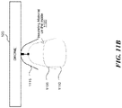
- the package 211 is loaded onto the drone 120 such that the package 211 rests in a hood (described below at least with reference to FIGS. 11A , 11B , 13 ), flush against the top and all four sides of the hood.
- a spool brake e.g., the package brake module 150
- the package brake module 150 is automatically engaged to prevent the suspension means 135 from lowering during the flight and therefore, prevent the package 211 from lowering.
- the package 211 is now secure, e.g., locked in place and may not rotate or shift due to protection from the package hood, cannot be lowered because of the spool brake, and cannot separate from the suspension means 135 because it cannot unlock itself off of the gravity activated male coupler 140 because it is flush against the top of the package hood.
- the package 211 is loaded in the center of and underneath the airframe of the drone 120 (e.g., as illustrated in FIGS. 13 , 14 , and 17A below). Such a mounting can improve the natural stability of the payload by lowering the center of gravity temporarily, until the package 211 is delivered.
- the drone 120 Upon reaching the delivery destination, the drone 120 prepares to deliver the package 211 at a delivery area 215 in the delivery destination.
- the delivery area can be any designated area in the delivery destination, e.g., a balcony of a house, a front lawn, a porch, an entrance of a business, a patio table in the front lawn.
- the drone 120 hovers in air above the delivery area 215 at a particular height from the ground, releases the spool brake and lowers the suspension means 135 to deliver the package 211 in the delivery area 215.
- the drone 120 continues to lower the suspension means 135 until the package 211 rests on the delivery area 215.
- the coupling member 140 is still engaged while the package 211 is being lowered as the weight of the package 211 keeps the coupling member 140 engaged.
- a pilot of the drone 120 has the ability to stop the descent of the package 211 if the safety of the delivery location is compromised.
- one of the factors considered in determining the particular height at which the drone 120 should hover for delivery is a minimum parachute deployment height.
- the minimum parachute deployment height is the minimum height from the ground at which the drone 120 is required hover if the parachute is to be deployed. If the hovering height of the drone 120 is less than the minimum parachute deployment height then the parachute may not be deployed. This can be dangerous because if the drone 120 crashes and the parachute is not able to be deployed, it can cause an injury to a human being or a property in the surrounding. Accordingly, the particular height at which the drone 120 has to hover for delivering a package is computed as a function of the minimum parachute deployment height.
- the drone 120 is configured to hover and deliver from a height of 4 meters plus height of a person plus margin of error to ensure safety for the recipient on the ground. If the minimum parachute deployment height changes, the minimum delivery height also changes accordingly.
- the coupling member 140 can be disengaged to release the package 211.
- the weight of the package 211 is offloaded from coupling member 140 resulting in the gravitational force exerted on the coupling member 140 to drop below a specified value, which enables the coupling member to be disengaged from the package 211, thereby releasing the package 211.
- the drone 120 retracts the suspension means 135, as illustrated in FIG. 2D .
- the package delivery module 130 senses the reduction of weight on the suspension means 135, determines the package 211 is delivered onto the delivery area 215 and retracts the suspension means 135 back onto the line spool.
- the operator or the package delivery module 130 can command the severing module 145 to cut the suspension means 135 and separate it from the drone 120.
- FIG. 2E is a block diagram illustrating an example of the locking mechanism, or coupling member of FIG. 1 , consistent with a particular example.
- the coupling member 140 attached to the suspension means 135 can be a male coupler, and the coupling counterpart 250 on the package 211 to which the coupling member 140 engages can be a female coupler, though various other configurations of the coupling member 140 and the coupling counterpart 250 are possible.
- the suspension means 135 can be a microfilament braided line and can be rated to handle a specified weight, e.g., up to 100 lbs.
- the coupling member 140 can operate as described with reference to FIGS. 2A-2D .
- the suspension means 135 is lowered to insert the male coupler 140 into the female coupler 250 that is installed in the package 211.
- the male coupler 140 is rotated clockwise in the female coupler 250, which locks the male and female couplers together.
- the package 211 will remain attached to the male coupler 140 and therefore, to the suspension means 135.
- the coupling member 140 can operate in automatic-coupling mode or a passive-coupling mode to lock and/or unlock the package 211.
- the coupling member 140 automatically couples the male and female couplers, e.g., rotates the male coupler 140 in the female coupler 250 after inserting the male coupler 140 into the female coupler 250, to hold the male and female couplers together in locked position so that when the package 211 is lifted off the surface it's resting on, the package 211 locks onto the suspension means 135, e.g., due to its weight.
- the package delivery module 130 lowers the suspension means 135 to the delivery area 215 and once the package 211 rests on the delivery area 215, the weight of the package 211 will be off the suspension means 135 and the package delivery module 130 automatically disengages the male and female couplers, e.g., rotates the male coupler 140 in a direction opposite to that of the locking, to unlock the male coupler 140 from the female coupler 250 thereby releasing the package 211.
- the package delivery module 130 then retracts the suspension means 135 onto the drone 120.
- the coupling member 140 can be caused to engage in various ways.
- the suspension means 135 can have a mechanism to automatically rotate the male coupler 140, or the package delivery module 130 can have a mechanism to rotate the suspension means 135 to rotate the male coupler 140.
- a package loading equipment e.g., in the loading facility associated with the base station 125 that automatically loads the package 211 to the drone 120 can have a mechanism to rotate the male coupler 140.
- one or more of the operations may be performed by a human user to lock or unlock the package 211, such as manually rotate the male coupler 140 in the female coupler 250 to lock or unlock the package 211.
- FIG. 2E the shape, size and any other configuration of the coupling member 140, the male and female couplers (or the drone 120 or any other part of the drone 120) illustrated in FIG. 2E is for illustration purposes only. The actual shape, size and other configurations can be different from what is illustrated in FIG. 2E .
- the coupling counterpart 250 can be affixed to a top wall of a payload container.
- the coupling counterpart 250 can include a plurality of protruding elements (e.g., four protrusions).
- the plurality of protruding elements can be evenly spaced around a surface of an opening in the coupling counterpart 250.
- the plurality of protruding elements can have a cross-section that is, for example, square shaped or circle shaped.
- a shape of the protruding elements can correspond with a shape of a hook element of the coupling member 140.
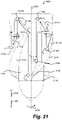
- FIG. 2F shows a side view on coupling member 140 in the direction of arrow A, shown in FIG. 2E .
- coupling member 140 is attached to a suspension means 135.
- the suspension means 135 can be controlled by a drone to lower and/or raise the coupling member 140.
- the coupling member 140 includes a plurality of hook elements 1620 (e.g., four hook elements), protruding from surface 1606 of the coupling member 140.
- An upper portion of any of the hook elements can include a slanted appendage 1624.
- the slanted appendage 1624 can be affixed to, or protrude from, an outer surface of the coupling member 140.
- the slanted appendage 1624 can include an underside 1626 sloped toward a hooked portion 1622 of the hook element 1620.
- the underside 1626 of the slanted appendage 1624 can be connected to the hooked portion 1622 such that a continuous surface extends from the underside 1626 to the hooked portion 1622.
- the underside 1626 can be slanted upward extending from a first side of the hooked portion 1622 to a second side of the hooked portion 1622.
- a top terminal end of the underside 1626 extends beyond a second side of the hooked portion 1622 or is in line with the second side of the hooked portion 1622. If the coupling member 140 is inserted into a coupling counterpart 250, protruding elements of the coupling counterpart 250 can glide along the underside 1626 causing the coupling member 140 to rotate out into an out-of-alignment position.
- An out-of-alignment position includes the protruding element not being above the hooked portion 1622.
- the threshold distance can be utilized to unlock the coupling member 140 from the coupling counterpart 250.
- a drone having a cable connected to the coupling member 140 can allow slack to develop in the cable causing the coupling member 140 to enter the coupling counterpart 250 beyond a threshold distance causing the out-of-alignment position. Since the hooks are not in position to attach the protruding elements in the out-of-alignment position, the drone can then retract the cable and bring the coupling member 140 up to the drone while leaving the coupling counterpart 250 with the container.
- FIGS. 2G-2J illustrate the coupling member 140 inserted into the coupling counterpart 250 from various perspectives.
- FIG. 2G shows an orthogonal view of the coupling member 140 inserted into the coupling counterpart 250.
- FIG. 2H is a top down view of the inserting member 142 inserted into the receiving member 144.
- FIG. 21 is a side view of the coupling member 140 inserted into the coupling counterpart 250.
- a side of the coupling counterpart 250 is shown as substantially transparent to show a position of the coupling member 140 within an opening of the coupling counterpart 250.
- Various embodiments including opaque sides for the coupling member 140 are contemplated.
- the example coupling member 140 defines first 1608 and second 1610 longitudinal directions, opposite to one another and parallel to a longitudinal axis 1602, and an azimuthal direction 1604 around the longitudinal axis 1602.
- the coupling member 140 comprises one or more guide paths which are configured to guide a corresponding protrusion of the coupling counterpart 250 from a locked position P locked to an unlocked position P unlocked .
- the coupling member 140 is free to rotate in the azimuthal direction 1604 and in a direction opposite to the azimuthal direction 1604.
- the coupling member 140 can also move along the longitudinal axis 1602 in both the first and second longitudinal directions 1608, 1610 by raising and lowering the coupling member 140 by retracting and unravelling the suspension member 135, as previously described.
- the example coupling member 140 comprises a surface 1606, in this case an outer surface, which, by virtue of the hook elements 1620, defines one or more guide paths which extend along the surface 1606.
- a guide path guides a protrusion of the coupling counterpart 250 from a locked position P locked within the guide path to an unlocked position P unlocked outside of the guide path.
- the protrusion may be manually moved into the locked position by a human operator, or by a mechanism on the drone 120 or suspension member 135 applying a rotational force which causes the coupling member 140 to rotate.
- the coupling member 140 and the coupling counterpart 250 are said to be engaged and locked together because the package (and therefore the coupling counterpart 205) and the coupling member 140 cannot be pulled apart in opposite directions along the longitudinal axis 1602.
- the protrusion is in the locked position P locked .
- the protrusion can be guided along the guide path (in the direction of the arrows) by moving the coupling member 140 relative to the stationary protrusion.
- the coupling member 1904 can be moved in the first longitudinal direction 1608 when the package is deposited on a delivery surface.
- the guide path can be formed by one or more structures protruding outwards from the surface 1606 in an outwards radial direction.
- the guide path can be formed by forming a groove within the surface 1606, where the groove extends into the surface in an inwards radial direction.
- the coupling member 140 may be formed from a relatively rigid material such as a metal or plastic.
- the protrusion, at position P locked is shown initially being within a guide path.
- the guide path comprises an engagement surface comprising a first part 1612.
- the first part 1612 is configured to abut the protrusion in the locked position P locked .
- the drone 120 may be hovering at a particular height above a delivery surface at this moment in time and can begin lowering the package by allowing, or causing, the suspension member 135 to unravel.
- the coupling member 140 therefore moves in the first longitudinal direction 1608 towards the delivery surface.
- the coupling counterpart 250 and the protrusion become stationary relative to the coupling member 140 which continues to move in the first longitudinal direction 1608.
- This relative movement causes the position of the protrusion to move relative to the coupling member 140 until it engages an egress surface along a second part 1614a.
- the second part 1614a receives the protrusion from the first part 1612.
- the second part 1614a is spaced from the first part 1612 along the longitudinal axis 1602 and has substantially the same azimuthal position as the first part 1612.
- At position Px the protrusion has engaged the second part 1614a.
- This second part 1614a is inclined and extends from a third part 1614b of the egress surface in the first longitudinal direction 1608 and in the azimuthal direction 1604.
- the engagement between the protrusion and the inclined surface of the second part 1614a causes the coupling member 140 to rotate in the azimuthal direction 1604.
- the weight of the coupling member 140, and the relatively low coefficient of friction between the protrusion and the inclined surface allows the coupling member 140 to rotate in this manner.
- the rotation and the movement in the first longitudinal direction 1608 continues until the third part 1614b engages the protrusion at point P Y .
- the third part 1614b therefore receives the protrusion from the second part 1614a in an out of alignment position.
- the drone 120 can retract the suspension member 135 to cause the coupling member 140 to move in the second longitudinal direction 1610.
- the third part 1614b releases the protrusion to the unlocked position P unlocked when the coupling member 140 is moved away from the coupling counterpart 250.
- the coupling member 140 has fully uncoupled from the coupling counterpart 250, so the package remains on the delivery surface as the drone 120 continues to retract the suspension member 135.
- the engagement surface 1612 and the egress surface of the guide path are defined by the hook element 1620, where the hook element 1620 protrudes from the surface 1606 of the coupling member 140.
- the hook element 1620 comprises a slanted appendage 1624, and the underside 1626 of the slanted appendage defines the egress surface 1614 of the guide path.
- the hook element 1620 further comprises a hooked portion 1622 which defines the engagement surface 1612.
- the hooked portion 1622 is connected to the underside 1626 of the slanted appendage 1624.
- a top terminal end of the underside 1626 of the slanted appendage 1624 defines the third part 1614b of the egress surface 1614.
- FIGS. 19 to 25 disclose another coupling member for which gravity assists both the coupling and uncoupling of the coupling member.
- FIGS. 3A and 3B collectively, referred to as FIG. 3 , is a schematic diagram of an example 300 for severing suspension means of a drone, consistent with various embodiments.
- the drone 120 retracts the suspension means 135.
- the suspension means 135 is pulled, e.g., when pulled by an animal or a person, such as a person 310, or when stuck in other objects, such as a tree, either when the suspension means 135 is being retracted or being lowered to deliver the package 211, the drone 120 can be dragged to the ground and crash, injure the person 310 and/or damage the property around the drone 120. Further, the drone 120 can be damaged or stolen.
- the severing module 145 When the suspension means 135 is pulled, the severing module 145 detects an additional load on the suspension means 135 and if the load is beyond a specified value, the severing module 145 severs the suspension means 135, as illustrated in FIG. 3B .
- the severing module 145 includes a nichrome cutting element 305 that is used to sever the suspension means 135.
- the suspension means 135 can pass through a nichrome cutting element 305, shown in FIG.
- the severing module passes an electric current of a certain rating through the nichrome cutting element 305, which generates a significant amount of heat causing the suspension means 135 to be severed at the portion where the nichrome cutting element 305 is in contact with the suspension means 135. Severing the suspension means 135 when the suspension means 135 is pulled or when the suspension means 135 is entangled in an obstacle will keep the drone 120 from crashing, being stolen, and/or causing damage to any person, animal or property in the surroundings.
- the suspension means 135 can be spooled around spindle 500 of the delivery mechanism 130 by threading a free end of a new line through a bottom hole 401 of the delivery mechanism 130, around a force sensor lever rod 403, through the nichrome cutting element 305, through tensioning rods 501a, 501b, and through a line spacer 503.
- the spindle 500 and associated motor 405 is an example of a means by which the suspension means 135 is lowered from the drone 120 or retracted into the drone 120.
- the spindle 500, motor 405 and nichrome cutting element 305 are preferably powered and controlled separately from other elements of the drone 120.
- FIG. 6 is a flow diagram a process 600 for locking and unlocking the package attached to the suspension means of the drone using a coupling member, consistent with various embodiments.
- the process 600 can be performed in the system 100 and using the drone 120 of FIG. 1 .
- the process of locking the package is performed when the package is picked up, and the process of unlocking is performed when the package is dropped off.
- the package delivery module 130 of the drone 120 lowers the suspension means 135 to pick-up a package, such as package 211, from a pick-up address or from the loading facility of the base station 125.
- the package delivery module 130 lowers the suspension means until the coupling member 140 is in a position to be attached or coupled to the package 211.
- the package delivery module 130 lowers the suspension means 135 until the male coupler 140 of the suspension means 135 is inserted into the female coupler 250 of the package 211.
- the package delivery module 130 can determine whether the coupling member 140 is in a position to be attached to the package 211 in various ways. For example, when the male coupler 140 is inserted into and rests in the female coupler 250, the weight of the male coupler 140 is off the suspension means 135 and the package delivery module 130 can determine that male coupler 140 is in position to be attached to the female coupler 250.
- the package delivery module 130 can determine the distance between the drone 120 and the package 211, e.g., using various on-board sensors, and lower the suspension means 135 based on the determined distance.
- the lowering of the suspension means 135 can be controlled by an operator of the drone 120.
- the coupling member 140 is engaged with the package 211 to lock the package 211 to the suspension means 135.
- the coupling member 140 can be operated, e.g., engaged and disengaged, in an automatic-coupling mode or a passive-coupling mode to lock or unlock the package, e.g., as described at least with reference to FIGS. 2E-J .
- the coupling member 140 continues to be engaged, e.g., due the weight of the package 211 on the coupling member 140 exerted by the gravitational force, causing the package 211 to be locked to the suspension means 135.
- the coupling member 140 is configured to engage only if the weight of the package 211 is exceeds a first specified value.
- the drone 120 flies to the delivery destination where the package has to be delivered.
- the application module 122 instructs the drone 120 to hover at the delivery destination at a particular height from the ground and instructs the package delivery module 130 to prepare for delivering the package 211.
- the package delivery module 130 lowers the suspension means 135 to deliver the package at a delivery area in the delivery destination, e.g., delivery area 215.
- the package delivery module 130 continues to lower the suspension means 135 until the package 211 rests on the delivery area 215.
- the coupling member 140 is still engaged while the package 211 is being lowered as the weight of the package 211 keeps the coupling member 140 engaged.
- the weight of the package 211 is offloaded from the coupling member 140.
- the weight on the coupling member 140 drops below a second specified value enabling the coupling member 140 to be disengaged, thereby releasing the package 211.
- the speed at which the suspension means 135 is lowered from the drone 120 or retracted into the drone 120, e.g., in blocks 605 and/or 625, can be regulated.
- the rate of descent of the suspension means 135 is decelerated as the package 211 reaches the ground or the surface on which the package 211 is to be delivered, e.g., in order to avoid any damage to the package 211 from the impact of the delivery.
- the speed at which the suspension means 135 is retracted into the drone is decreased as the package 211 or the coupling member 140 reaches the drone 120, e.g., in order to avoid the package 211 or the coupling member 140 (when there is no package attached to the suspension means 135) from being retracted too forcefully into the drone 120 and harm the spool of the suspension means 135.
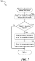
- FIG. 7 is a flow diagram of a process for severing the suspension means of a drone, consistent with various embodiments.
- the process 700 can be performed in the system 100 and using the drone 120 of FIG. 1 .
- the package delivery module 130 detects an additional weight on the suspension means 135.
- the drone 120 has on-board sensors that can detect a change in load carried by the suspension means 135. For example, when the suspension means 135 is pulled by an animal or a person, or when the suspension means 135 is entangled in an obstacle like a tree, there can be an additional load added to the suspension means 135.
- the package delivery module 130 determines whether the changed weight exceeds a specified value. If the weight does not exceed the specified value, the process 700 returns. On the other hand, if the weight exceeds the specified value, at block 715, the package delivery module 130 instructs the severing module 145 to sever the suspension means 135.
- the severing module 145 severs the suspension means 135.
- the severing module 145 includes a nichrome cutting element 305 that is used to sever the suspension means 135.
- the severing module 145 passes an electric current of a certain rating through the nichrome cutting element 305, which generates a significant amount of heat causing the suspension means 135 to be severed at the portion where the nichrome cutting element 305 is in contact with the suspension means 135.
- the package delivery module 130 In determining whether the weight exceeds the specified value, the package delivery module 130 considers various factors, e.g., weight of the package if the package is still attached to the suspension means 135, change in weight because of the haphazard movement of the suspension means 135 due to strong winds, etc. The package delivery module 130 will calculate the change in weight accordingly.
- one or more operations of the processes 600-700 can be performed manually, e.g., remotely by an operator of the drone 120 from the base station 125, or automatically by the drone 120.
- the package delivery module 130 can automatically deliver the package 211 or wait to receive instructions from the operator of the drone 120.
- the severing module 145 can sever the suspension means 135 automatically or wait for the operator to command the severing module 145 to sever the suspension means 135.
- FIG. 8 is a block diagram of a container 800 for delivering food, consistent with various embodiments.
- the drone 120 can be used to deliver and/or pickup goods in a wide variety of containers.
- the container 800 is similar to the package 211 of FIG. 2 .
- the container 800 can include multiple compartments for holding different types of payload and/or different types of payload that are temperature sensitive, e.g., food, medicine, blood.
- the container 800 can have a first compartment for holding a first type of payload that is to be maintained in a first specified temperature range, and a second compartment for holding a second type of payload that is to be maintained in a second specified temperature range.
- the container 800 includes various compartments for carrying various types of food, e.g., liquid food, solid food, hot food and/or cold food.
- the container 800 can have separate sections for different types of food.
- the container 800 includes a hot food compartment 805 and a cold food compartment 810.
- the hot food and cold food compartments are separated by a wall 825, which can have an insulated material.
- the container 800 includes ventilation 815 to keep hot food, such as chips, crisp.
- the container 800 can be connected to the suspension means 135 of the drone 120 at a coupler 820.
- the coupler 820 is similar to the female coupler 250 of FIG. 2 .
- the coupler 820 is offset to a compartment that carries heavier food, e.g., drinks, to ensure the weight is centered when heavier items are included.
- the entire container 800 is delivered to the customer.
- the container 800 can be made of paper, cardboard or other suitable materials.
- the container includes temperature insulating material, such as polystyrene, Mylar TM or other materials.
- the container may be fully or partially constructed from such temperature insulating materials.
- the insulating material helps keep the contents of container within a desired temperature range.
- Mylar TM is particularly useful since it helps achieve food quality requirements.
- the container 800 can have one or more lids which, when opened, provide access to the contents inside. In some embodiments, the lids open away from each other so that any area/compartment in the container 800 can be accessed conveniently.
- the container comprises impact mitigating material, such as a deformable material. The impact mitigating material significantly improves safety in the event that the container is accidentally dropped from the drone 120.
- FIGS. 9A and 9B collectively referred to as FIG. 9 , is a block diagram of a container 900, consistent with various embodiments.
- the container 900 can be round or round-like, e.g., elliptical, conical, in shape. In some embodiments, the shape of the container 900 can be representative of a bucket.
- the container 900 has a removable lid 950, which can be cylindrical, as illustrated in FIG. 9B .
- the container 900 like the container 800 of FIG. 8 , can include various compartments for carrying various types of food, e.g., liquid food, solid food, hot food and/or cold food.
- the compartments can be designed such that when a set of food items are placed, the container 900 is well balanced, e.g., weight is centered.
- the two compartments for holding liquids, e.g., drinks are located diametrically opposite to each other in the container 900 so as to center the weight.
- the container 900 can also include a compartment for carrying various types of cutlery.
- the container 900 can have means for facilitating a customer to hold or carry the container.
- the container 900 includes a pair of finger grips into which the customer can slip in his/her fingers and carry the container 900.
- the finger grips can be affixed to the container 900, or the lid 950 of the container 900 if the lid 950 of the container 900 can be locked/secured to the container 900.
- the container 900 is modular, e.g., can be made using a number of card plates, e.g., made out of cardboard, paper and/or other suitable material.
- the card plates (not illustrated) can have fold lines, slotted lines and/or slots along which one can fold the card plates to form the container 900 or a portion thereof.
- the card plates can then be assembled together to form the container 900.
- the modular container portions are adjustable to carry payload of different sizes in different compartments, e.g., pizza in one compartment and medicine in another compartment.
- the container 900 (or even the container 800) can be configured to pick up and/or deliver items other than food, e.g., goods such as electronics, apparel, shoes.
- the container 900 can be configured to have various types of compartments based on the type of the goods that have to be picked up/delivered.
- the container 900 has foam or other similar material in the base, as illustrated in the example 1011 of FIG. 10A .
- the foam-based base can serve various purposes. For example, the foam-based base can hold the packages placed in the container 900 in a stable position by minimizing the movement of the package during the flight.
- the foam-based base can act an impact-absorbing base by provide additional cushion between a soft outer layer of cardboard of the base of the container 900 and a potentially hard inner object such as a bottle of wine which makes it safer if the container 900 falls off the drone 120 and hits a person or property.
- the foam base enables delivering of a variety of shaped objects whether rectangular, triangular, elliptical, etc. (provided they can fit in the container 900, and be held in position by the foam-based base). For example, if a box containing a pair of shoes is to be delivered, the box would be placed inside the container 900, it would be held in position by foam, and then the container 900 holding the box could be picked up to the drone 120; then delivered at the destination.
- the container 900 has no corners or edges on the exterior surface of the container 900.
- the container 900 can have a spherical underside with a flat bottom that eliminates corners/edges.
- the corners can be rounded as illustrated in the example 1010 of FIG. 10A .
- the rounded corners can be safer than the straight edged corner.
- FIG. 10B is a top view of a square shaped container 1020 with round corners, consistent with various embodiments.
- the container can be held onto the drone 120 using a conical hood.
- FIG. 11A is a block diagram of a hood 1105 that holds a container 1110 onto the drone 120, consistent with various embodiments.
- the container 1110 is similar to the container 900, container 800 or the package 211.
- a package to be delivered can be placed in the container 1110.
- the container can turn/rotate/move in the wind and the container may not align itself in a container housing fixed to the drone 120.
- the container 1110 mounts correctly on the underside of the drone 120, e.g., in the container housing 1115, the container 1110 is affixed to a hood 1105, which is then drawn into the container housing 1115 by the suspension means, e.g., suspension means 135.
- the hood 1105 can be conical or conical-like, e.g., spherical, in shape.
- the hood 1105 has a means to connect to the suspension means.
- the lid of the container 1110 can be designed as the conical hood 1105.
- the hood 1105 is affixed to the container 1110, e.g., to the lid of the container 1110.
- the hood 1105 When the container 1110 is lifted up by the drone 120, the hood 1105 is drawn into the container housing 1115 and the container 1110 is housed within the container housing 1115 of the drone 120.
- the container housing 1115 is a concave structure, e.g., conical concave structure, that can conveniently house the entire container 1110 or a portion of the container 1110, e.g., a significant portion of the container 1110, so as to keep the container 1110 from moving due to wind while in flight.
- FIG. 11B is a block diagram illustrating the container 1110 housed in the container housing 1115 of the drone 120.
- the hood 1105 is a concave structure and the container housing is a convex structure. This design may be advantageous for certain drones because it still enables self-aligning of the container in the container housing and has thicker padding at the center of gravity of the drone.
- having the container housing 1115 and the container hood 1105 in the conical shape facilitates easy mounting, alignment and/or housing of the container 1110 in the container housing 1115 compared to other shapes. For example, if the container housing 1115 is of a square shape, and if the container is also of square shape, it may be difficult to align the container 1110 within the container housing 1115, especially if there is any wind.
- the hood 1105 contains insulating material 1120 on the interior walls of the hood to keep the food warm/cold.
- the amount of surface area of the container 1110 that is in contact with the hood 1105 has to be maximized, e.g., it has to be a round surface on surface, which can mean the container 1110 and the hood 1105 may have to be circular/round or conical in shape.
- the insulating material 1120 can be a material that provides insulation against electro-magnetic fields and/or electro-static discharges, e.g., faraday cage insulation, which can be helpful for transporting electronic/magnetic goods.
- FIG. 12A is a block diagram of an example of a parachute affixed to a container, consistent with various embodiments.
- the container 1110 to be dropped off at a delivery location can be installed with a parachute 1205, e.g., made of cloth, paper or paper-type material.
- the parachute 1205 can be folded and installed on top of the container.
- the parachute 1205 has a hole 1210, e.g., round in shape, in the top and middle, which is where the container 1110 may be mounted to the suspension means 135 of the drone 120.
- the parachute 1205 can be attached to the container 1110 at a number of locations, e.g., at least 3 locations.
- FIG. 12B is a block diagram of an example in which the parachute of FIG. 12 A is deployed, consistent with various embodiments.
- the parachute 1205 is connected to the container 1110 at four locations, e.g., near the four corners of the container 1110.
- the parachute 1205 can be configured to deploy in response to a trigger. In some embodiments, the parachute 1205 will deploy if the suspension means 135 of the drone 120 snaps.
- FIG. 13 is a block diagram of the drone 120 with various parts of the package delivery module of FIG. 1 , consistent with various embodiments.
- the drone 120 includes arm guards 1305 that are configured to protect the arms of the drone 120, e.g., against impact on crash landing, and also, the propellers 1315 installed on the arms.
- the package delivery module 130 includes a "dog bowl” like structure 1310 onto which a container housing 1115 fits snugly.
- the package delivery module 130 includes the container housing 1115 to house the package during the flight.
- the packages, e.g., container 1110 are mounted in the center of the drone 120, and therefore the container housing 1115 is mounted in the center of the drone 120.
- the weight of the container 1110 is centered at the middle of the drone 120, e.g., even with different size/weight containers, which enables the drone 120 to have stability in flight.
- the container housing 1115 also limits and/or hide the wobbling of the container 1110 during flight.
- the drone 120 may not include the container housing 1115, e.g., if the suspension means 135 is tight enough to limit the wobbling of the package.
- the package delivery module 130 includes the container hood 1105.
- the hood 1105 contains insulating material on the interior walls, e.g., to keep the food being delivered warm/cold.
- the hood can be installed with sensor to monitor and regulate the temperature to ensure the food arrives to the customer at guaranteed food quality standards (and at safe temperatures).
- the hood 1105 can log the temperature data and store it and/or report it to an on-board processor (not illustrated) of the drone 120 and/or to the operator.
- the on-board processor or the operator can then take necessary steps, e.g., increase or decrease the temperature, to keep the food at required temperatures.
- the drone 120 typically has a temperature controlling mechanism, e.g., heating elements and/or cooling elements in the package, to regulate the temperature of the food during the flight, and is powered by the power supply of the drone 120 and/or of the package delivery module 130.
- the insulating material can also provide electro-magnetic and/or electro-static shielding.
- the package delivery module 130 also includes an anti-roll feature.
- the anti-roll feature facilitates the drone 120 to land on the container housing 1115 even without the hood 1105 inside it, e.g., for emergencies.
- the anti-roll feature also prevents tipping, and even if the drone 120 tilts, the propellers 1315 cannot hit the ground, as shown by the angle depicted in FIG. 14 .
- the container 1110 to be delivered by the drone 120 can be of various shapes and sizes.
- the container 1110 is similar to the package or container described at least with reference to FIGS. 2 , 8 , 9A , 9B , 10A and 10B .
- the container 1110 is designed so it can carry a variety of different product sizes including parcels and fast food with none-to-minimum changes to the container 1110 (besides adding inserts to ensure the goods that are delivered have a snug and insulated fit so they don't roll around and are kept at the correct temperature).
- the container 1110 can include variable padding based on the center of gravity of the drone 120, e.g., padding is thickest where the center of gravity is of greatest which makes it safer for people upon impact when the container crash lands on people.
- the hood 1105 can also cover the container in foam, which provides an additional safety measure. For example, if the suspension means 135 is severed and when the container 1110 falls, in the event of an impact with a person, the container 1110 hits the person with the foam rather than with a corner or edge, which makes it safer.
- the components or parts of the package delivery module 135 or the drone 120 illustrated in FIG. 13 are in just one embodiment. Other embodiments can have more parts or have fewer parts. For example, in one embodiment, the package delivery module 135 may not have the dog bowl 1310.
- FIGS. 15A , 15B and 16 also illustrate various configurations of the container 1110.
- FIG. 15A is a block diagram of a first hex-box container 1500 for delivering food, consistent with various embodiments.
- the first hex-box container 1500 can be used to carry food and drinks such as a pizza and a beverage, e.g., soda or wine.
- the first hex-box container 1500 is an adjustable hex box, which has three compartments stacked one over the other. The top two of the three compartments can be used to carry pizza, and the bottom compartment can be used to carry drinks.
- the first hex-box container 1500 can be made of paper, cardboard or a similar suitable material and can be assembled easily from an initial flat sheet, e.g., by folding the sheet along the fold lines 1525.
- the first hex-box container 1500 can be adjusted to three stacked compartments or to two stacked compartments.
- the first hex-box container 1500 can have adhesive pads 1505 under the lid using which the left lid 1510 and the right lid 1515 can be secured to each other.
- the lids also have one or more slots 1520 for the coupler of the container, which connects to the suspension means 135.
- the lids can have more than slot for the coupler as the position of the coupler of the first hex-box container 1500 can change depending on whether the first hex-box container 1500 is two layered container or a three layered container.
- FIG. 15B is a block diagram of a second hex-box container for delivering food, consistent with various embodiments.
- the second hex-box container 1530 in FIG. 15B shows a pair of wine bottles housed in the slots in the bottom-most compartment 1535 of the second hex-box container 1530.
- the second hex-box container 1530 can also be configured to carry one or more drinks.
- the second hex-box container 1530 will have a single slot for carrying one drink and two slots for two drinks.
- the second hex-box container 1530 can be configured, e.g., folded across appropriate fold lines, to have two layers for carrying solid food, e.g., pizza, and one bottom layer for beverages as shown by example 1540, and configured to have one layer for carrying solid food and one bottom layer for beverages as shown by example 1545.
- the shape and size of the slots can vary and depends the shape and size of the drink containers to be carried.
- the configuration of the containers e.g., shape, size, the number of compartments, are completely configurable and is not restricted to the illustrated embodiments.
- FIG. 16 is a block diagram of another container for carrying beverages, consistent with various embodiments.
- the container 1600 is a rectangular or square shaped container configured to carry a beverage.
- the container has slots for carrying two beverages, e.g., a pair of wine bottles.
- the beverages in the container can be wrapped with an insulating layer 1605 as illustrated to keep the beverages at a constant temperature or to minimize the temperature change.
- the container 1600 also has a slot for placing the coupler, which is used to attach the container 1600 to the suspension means 135 of the drone 120.
- the container 1600 is similar to the container 1110 or the package 211.
- FIGS. 17A-17E collectively referred to as FIG. 17 , is a block diagram illustrating an example of delivering a package using a drone, consistent with various embodiments.
- the example can be implemented in the system 100 of FIG. 1 and using the drone 120.
- the example is similar to the example 200 illustrated in FIG. 2 .
- the drone 120 is in flight enroute to a delivery destination to deliver a package, e.g., container 1110.
- the container 1110 is attached to the drone 120 via the suspension means 135 and is locked to the suspension means 135 via the coupling member 140.
- the drone 120 Upon reaching the delivery destination, the drone 120 prepares to lower the container 1110 at a delivery area in the delivery destination. As illustrated in FIG. 17B , the drone 120 while hovering at the delivery area at a particular height from the ground, lowers the suspension means 135 to deliver the container 1110. The hood 1105 is lowered to deliver the container 1110. While FIG. 17B illustrates the container 1110 being visible from outside the hood 1105, note that the container 1110 can be concealed in the hood 1105. The drone 120 continues to lower the suspension means 135 until the container 1110 rests on the delivery area 215, as illustrated in FIG. 17C . When the container 1110 rests on the delivery area 215, e.g., the ground, the coupling member 140 is disengaged to release the container 1110. The coupling member 140 can be operated in automatic-coupling mode or a passive coupling-mode to unlock, as described at least with reference to FIG. 2E .
- the drone 120 retracts the hood 1105 as illustrated in FIG. 17D .
- the drone 120 continues to retract the suspension means 135 until the hood 1105 is secured into the container housing 1115, as illustrated in FIG. 17E .
- the configuration of the hood 1105 and the container housing 1115 can enable self-aligning retraction of the container 1110, which enables the package delivery mechanism to perform pickups in addition to deliveries.
- the self-aligning retraction can also facilitate mid-delivery aborts, e.g., aborting delivery midway and retracting the container 1110 back to the container housing 1115.
- the packages can be picked up from or delivered to consumers while the drone 120 is in hover.
- the hood 1105 lowers with the container 1110, in some embodiments, if the suspension mechanism 135 is severed, the likelihood of the container 1110 landing on its edge on someone is reduced significantly and therefore, it is more safer. Also the hood 1105 can keep the hot food hot on its the way to the destination. Further, since the container 1110 is concealed in the hood 1105, after the container 1110 is delivered on the ground, the hood 1105 lifts away to reveal the container 1110, which provides a magical effect of the container 1110 appearing all of a sudden.
- FIG. 18 is a block diagram of a computer system as may be used to implement features of the disclosed embodiments.
- the computing system 1800 may be used to implement any of the entities, components, modules, mechanisms, or services depicted in the examples of the foregoing figures (and any other described in this specification).
- the computing system 1800 may include one or more central processing units (“processors") 1805, memory 1810, input/output devices 1825 (e.g., keyboard and pointing devices, display devices), storage devices 1820 (e.g., disk drives), and network adapters 1830 (e.g., network interfaces) that are connected to an interconnect 1815.
- processors central processing units
- the interconnect 1815 is illustrated as an abstraction that represents any one or more separate physical buses, point to point connections, or both connected by appropriate bridges, adapters, or controllers.
- the interconnect 1815 may include, for example, a system bus, a Peripheral Component Interconnect (PCI) bus or PCI-Express bus, a HyperTransport or industry standard architecture (ISA) bus, a small computer system interface (SCSI) bus, a universal serial bus (USB), IIC (I2C) bus, or an Institute of Electrical and Electronics Engineers (IEEE) standard 1394 bus, also called "Firewire”.
- PCI Peripheral Component Interconnect
- ISA HyperTransport or industry standard architecture
- SCSI small computer system interface
- USB universal serial bus
- I2C IIC
- IEEE Institute of Electrical and Electronics Engineers
- the memory 1810 and storage devices 1820 are computer-readable storage media that may store instructions that implement at least portions of the described embodiments.
- the data structures and message structures may be stored or transmitted via a data transmission medium, such as a signal on a communications link.
- Various communications links may be used, such as the Internet, a local area network, a wide area network, or a point-to-point dial-up connection.
- computer readable media can include computer-readable storage media (e.g., "non-transitory” media) and computer-readable transmission media.
- the instructions stored in memory 1810 can be implemented as software and/or firmware to program the processor(s) 1805 to carry out actions described above.
- such software or firmware may be initially provided to the processing system 1800 by downloading it from a remote system through the computing system 1800 (e.g., via network adapter 1830).
- programmable circuitry e.g., one or more microprocessors
- special-purpose hardwired circuitry may be in the form of, for example, one or more ASICs, PLDs, FPGAs, etc.
- FIGS. 2A-J described a particular example of a coupling member which allows a package to be uncoupled automatically, via gravity, without human intervention or without some other mechanism to rotate the coupling member or suspension means.
- Initial attachment of the coupling member to the package requires the coupling member to be rotated relative to the package.
- An improved coupling member will now be described which not only enables automatic uncoupling, but also enables automatic coupling.
- the rotation is automatic in the sense that several inclined surfaces on the coupling member cause the rotation by simply moving the coupling along a longitudinal axis.
- the primary difference between the coupler of FIGS. 2A-J and the improved coupling member is that the improved coupling member has a guide path with two ends, the two ends forming an inlet and an outlet. This allows a protrusion to be guided through the inlet towards a locking position when the coupling member is coupled to the coupling counterpart, and then guided from the locking position to the outlet when uncoupled from the coupling counterpart.
- the coupler of FIGS. 2A-J has a guide path with only one end which acts as both the inlet and outlet.
- the guide path comprises several inclined surfaces to cause the coupler to rotate several times. Again, this is in contrast with the guide path of the coupler of FIGS. 2A-J , which has a single inclined surface.
- Figure 19A depicts a UAV 1900 having a payload delivery mechanism comprising a retractable suspension member 1902 and the improved coupling member 1904 according to an embodiment, attached to a lower end of the suspension member 1902.
- Figure 19A shows the UAV 1900 before it has picked up a payload container 1906 comprising a payload.
- the suspension member 1902 is released so that it moves in a first longitudinal direction 1908, towards the payload container 1906.
- the combined weight of the suspension member 1902 and the improved coupling member 1904 causes the coupling member to move in this direction.
- Figure 19B depicts the UAV 1900 at a later time.
- the coupling member 1904 has been lowered by the suspension member 1902 to the extent that it has now been received within a coupling counterpart 1912 located on/in a container comprising the payload container 1906.
- the coupling counterpart 1912 comprises one or more protrusions which engage with the coupling member 1904 to allow the payload container to be attached to the coupling member 1904.
- the coupling member 1904 is shown within the coupling counterpart 1912 as dashed lines.
- This rotation occurs without human intervention, and without the UAV applying an external force to cause the coupling member 1904 or the suspension member 1902 to rotate. Instead, the rotation occurs through the motion of the coupling member 1904 in the first longitudinal direction 1908 (due to gravity) and the abutment of the protrusion with the inclined surface on the coupling member 1904.
- Figure 19C depicts the UAV 1900 at a later time.
- the coupling member 1904 has been fully inserted into the coupling counterpart 1912 and drawn back towards the UAV in a second longitudinal direction 1910.
- Initial motion in the second longitudinal direction 1910 again causes the coupling member 1904 to rotate due to the engagement of the protrusion with another inclined surface. This rotation causes the protrusion to move into a locking position, such that continued motion in the second longitudinal direction 1910 locks the coupling member 1904 and the coupling counterpart 1912 together.
- the weight of the payload container 1906 which acts in the first longitudinal direction 1908, keeps the coupling member 1904 and the coupling counterpart 1912 locked together as the payload container 1906 is transported to a delivery destination.
- Figure 19D depicts the UAV 1900 after the payload container 1906 has been fully retracted into a container housing of the UAV 1900 (shown in Figure 19D with dashed lines).
- the payload container may be stored this way until the UAV 1900 arrives at its delivery destination.
- the UAV 1900 can hover at a certain distance above a delivery surface.
- Figure 19D therefore also depicts the UAV hovering above the delivery surface.
- the UAV 1900 can lower the payload container 1906 towards the delivery surface by causing the suspension member 1902 to unwind.
- the weight of the payload container 1906 and the coupling member 1904 pulls the payload container 1906 and coupling member 1904 in the first longitudinal direction 1908 towards the ground.
- Figure 19C can also represent the lowering of the payload container 1906 towards the delivery surface.
- Figure 19B can also be used to depict the payload container 1906 as it engages the delivery surface.
- the payload container 1906 engages the surface
- the payload container 1906 is no longer moving in the first longitudinal direction 1908.
- the weight of the coupling member 1904 means that the coupling member 1904 is still moving in the first longitudinal direction 1908, so moves relative to the coupling counterpart 1912.
- Another inclined surface of the coupling member 1904 again engages the protrusion due to the relative movement.
- the engagement with the inclined surface causes the coupling member 1904 to rotate as the coupling member 1904 continues to move in the first longitudinal direction 1908.
- the UAV 1900 can retract the suspension member 1902 and thereby move the coupling member 1904 in the second longitudinal direction 1910.
- FIG. 19A therefore can also be used to depict the release of the coupling member 1904 as the suspension member 1902 draws the coupling member 1904 in the second longitudinal direction 1910. Therefore again, the coupling member 1904 is automatically uncoupled from the payload container 1906 without human intervention or without the UAV 1900 applying an additional force to cause the coupling member 1904 or suspension means 1902 to rotate.
- Figure 20 depicts a more detailed view of the coupling member 1904 attached to the suspension member 1902, and the coupling counterpart 1912 affixed to an upper surface of a payload container 1906.
- the coupling counterpart 1912 comprises one or more protrusions 2000 which engage the coupling member 1904.
- the coupling member 1904 is a male connector and is configured to fit within a female coupling counterpart 1912.
- the coupling counterpart 1912 comprises an inner surface from which the protrusion projects inwards, in a radial direction.
- the coupling member 1904 may be a female connector and is configured to fit around an outer perimeter of a male coupling counterpart 1912.
- the coupling member 1904 may be affixed to the payload container 1906 and the coupling counterpart 1912 may be attached to the suspension member 1902.
- Figure 21 depicts an enlarged view of the coupling member 1904 according to an embodiment.
- the example coupling member 1904 defines first 1908 and second 1910 longitudinal directions, which point opposite to one another and are parallel to a longitudinal axis 2100 defined by the coupling member 1904.
- An outer surface 2104 of the coupling member 1904 extends in an azimuthal direction 2102 around the longitudinal axis 2100.
- the coupling member 1904 can also move along the longitudinal axis 2100 in both the first and second longitudinal directions 1908, 1910 by raising and lowering the coupling member 1904 by retracting and unravelling the suspension member 1902.
- Figure 22A depicts a simplified view of the coupling member 1904 depicted in Figure 21 .
- Figure 22B depicts a top down view of the coupling member 1904, which more clearly indicates the azimuthal direction 2102.
- the example coupling member 1904 comprises a surface 2104, in this case an outer surface, comprising one or more guide paths which extend around the surface 2104.
- a guide path guides a protrusion of the coupling counterpart 1912 from an inlet 2106 of the guide path to an outlet 2108 of the guide path.
- the coupling member 1904 can guide the protrusion into a locking position, where the coupling member and coupling counterpart are said to be locked together.
- the protrusion is guided by moving the coupling member 1904 relative to the stationary protrusion.
- the guiding can be achieved by simply moving the coupling member 1904 in the first and second longitudinal directions 1908, 1910 and allowing the coupling member 1904 to rotate as the protrusion engages a number of surfaces within the guide path.
- the guide path can be formed by various structures protruding outwards from the surface 2104 in an outwards radial direction. These structures form a number of surfaces which can engage a protrusion of the coupling counterpart 1912.
- the guide path can be formed by forming a groove within the surface 2104, where the groove extends into the surface in an inwards radial direction.
- the coupling member 1902 may be formed from a relatively rigid material such as a metal or plastic.
- the protrusion is initially received in an inlet 2106.
- the guide path at the inlet tapers and therefore narrows in width as it extends in the second longitudinal direction 1910. This tapered shape is particularly useful to more easily guide the protrusion into the guide path.
- the arrows in Figure 21 depict the relative movement of a protrusion through a guide path as the coupling member 1904 moves in the first and second longitudinal directions 1908, 1910 and is caused to rotate as the protrusion engages a number of surfaces within the guide path.
- the protrusion at position P inlet , is shown initially being received with a guide path via the inlet 2106 as the coupling member 1904 moves in the first longitudinal direction 1908 towards the coupling counterpart 1912. As the coupling member 1904 continues to move in the first longitudinal direction 1908, the position of the protrusion moves relative to the coupling member 1904. At position P 1 the protrusion engages an ingress surface along a first part 2110a of the ingress surface. This first part 2110a is inclined and extends from a second part 2110b of the ingress surface in the first longitudinal direction and in the azimuthal direction.
- the engagement between the protrusion and the inclined surface of the first part 2110a causes the coupling member 1904 to rotate in the azimuthal direction 2102.
- the rotation and the movement in the first longitudinal direction 1908 continues until the second part 2110b abuts the protrusion at point P 2 .
- the second part 2110b therefore receives the protrusion from the first part 2110a.
- This abutment stops or limits further movement and rotation of the coupling member 1904.
- the weight of the coupling member 1904, and the relatively low coefficient of friction between the protrusion and the inclined surface allows the coupling member 1904 to rotate in this manner.
- the suspension member 1902 would begin to go slack.
- the UAV 1900 can retract the suspension member 1902, and cause the coupling member 1904 to move in the second longitudinal direction 1910, which causes the position of the protrusion to move relative to the coupling member 1904 until it engages a locking surface along a third part 2112a.
- the third part 2112a therefore receives the protrusion from the second part 2110b.
- the third part 2112a is spaced from the second part 2110b along the longitudinal axis 2100 and has substantially the same azimuthal position as the second part 2110b. At position P 3 the protrusion has engaged the third part 2112a.
- This third part 2112a is inclined and extends from a fourth part 2112b of the locking surface in the second longitudinal direction and in the azimuthal direction.
- the engagement between the protrusion and the inclined surface of the third part 2112a causes the coupling member 1904 to rotate in the azimuthal direction 2102.
- the rotation continues until the fourth part 2112b abuts the protrusion at point P 4 .
- the protrusion can be said to be in a locked position, and so the coupling member 1904 is in a locking position relative to the coupling counterpart 1912.
- the fourth part 2112b therefore receives the protrusion from the third part 2112a.
- the coupling member 1904 continues to move in the second longitudinal direction 1910. Because the protrusion at point P 4 is trapped within a "U", "V" or hook-shaped fourth part 2112b of the guide path, the coupling counterpart 1912, and therefore the payload, can be lifted away from a surface by the UAV 1900. The payload can then be transported to its delivery destination.
- the payload can be lowered in the first longitudinal direction 1908 by allowing the suspension member 1902 to unwind.
- the coupling counterpart and the protrusion become stationary relative to the coupling member 1904 which continues to move in the first longitudinal direction 1908.
- This relative movement causes the position of the protrusion to move relative to the coupling member 1904 until it engages an egress surface along a fifth part 2114a.
- the fifth part 2114a therefore receives the protrusion from the fourth part 2112b.
- the fifth part 2114a is spaced from the fourth part 2112b along the longitudinal axis 2100 and has substantially the same azimuthal position as the fourth part 2112b.
- the fifth part 2114a of the particular guide path being described is obscured from view towards the rear side of the coupling member 1904.
- the fifth part 2114a of another adjacent guide path is used to describe the remaining features of the guide path.
- the protrusion has engaged the fifth part 2114a.
- This fifth part 2114a is inclined and extends from a sixth part 2114b of the egress surface in the first longitudinal direction and in the azimuthal direction.
- the coupling member 1904 continues to move in the first longitudinal direction 1908 the engagement between the protrusion and the inclined surface of the fifth part 2114a causes the coupling member 1904 to rotate in the azimuthal direction 2102.
- the rotation and the movement in the first longitudinal direction 1908 continues until the sixth part 2114b abuts the protrusion at point P 6 .
- the sixth part 2114b therefore receives the protrusion from the fifth part 2114a. This abutment stops or limits further movement and rotation of the coupling member 1904.
- the suspension member 1902 would begin to go slack. At this point, the UAV 1900 can retract the suspension member 1902, and cause the coupling member 1904 to move in the second longitudinal direction 1910, which causes the position of the protrusion to move relative to the coupling member 1904 until it is released towards and out of the guide path outlet 2108 at position P outlet . At this point, the coupling member 1904 has fully uncoupled from the coupling counterpart 1912, so the payload container remains on the delivery surface as the UAV 1900 continues to retract the suspension member 1902.
- Figure 23 depicts the coupling member of Figure 21 again to more clearly illustrate other features of the inlet 2106 to the guide path.
- the inlet 2106 in this example comprises an inlet surface 2116 which has a curvature in the second longitudinal direction and in the azimuthal direction.
- the inlet surface 2116 can be used to guide the protrusion towards the first part 2110a by causing the coupling member 1904 to rotate in a direction opposite to the azimuthal direction when the coupling member 1904 is initially moved in the first longitudinal direction 1908 towards the coupling counterpart when the payload container 1906 is being collected by the UAV 1900.
- the inlet surface 2116 comprises a seventh part 2118, the seventh part 2118 being spaced from the sixth part 2114b along the longitudinal axis 2100 and having substantially the same azimuthal position as the sixth part 2114b such that the protrusion is prevented from entering the outlet 2108 and engaging the sixth part 2114b when the coupling member 1904 moves in the first longitudinal direction 1908 towards the coupling counterpart 1912.
- P inlet is the position of the protrusion as it first enters the inlet 2106 as the coupling member 1904 moves in the first longitudinal direction 1908 towards the coupling counterpart 1912.
- the protrusion is not aligned with the first part 2110a because the protrusion has a different azimuthal position to the first part 2110a. Therefore, as the coupling member 1904 continues to move in the first longitudinal direction 1908, the protrusion engages the inlet surface 2116 along a seventh part 2118 at position P 7 .
- the inlet surface 2116 and therefore the seventh part 2118 has a curvature that extends in the first longitudinal direction and in the azimuthal direction.
- the coupling member 1904 continues to move in the first longitudinal direction 1908 the engagement between the protrusion and the surface of the inlet surface 2118 causes the coupling member 1904 to rotate in a direction opposite to the azimuthal direction 2102.
- the rotation and the movement in the first longitudinal direction 1908 continues until the first part 2110a receives the protrusion at point P 1 .
- the protrusion engages the seventh part 2118, it cannot accidentally enter the outlet 2108 because the seventh part 2118 blocks access to the outlet 2018 and the sixth part 2114b.
- the protrusion cannot erroneously enter the guide path in the wrong direction.
- the outlet 2108 can be said to be arranged in a direction substantially perpendicular to the longitudinal axis 2100, which means that movement in along the longitudinal axis 2100 does not allow the protrusion to enter the outlet 2108.
- the coupling member 1904 advantageously has a generally cylindrical form to allow for a fluid rotation within the coupling counterpart 1912.
- the bottom end of the coupling member 1904 has a tapered profile to assist in guiding the coupling member 1904 into the coupling counterpart 1912.
- Figures 21-23 depict the width of the coupling member 1904 narrowing in the first longitudinal direction. As the coupling member 1904 is being lowered towards the coupling counterpart 1912, and is slightly misaligned with the coupling counterpart 1912, the tapered or pointed end can help guide the coupling member 1904 back towards the center of the coupling counterpart 1912.
- Figure 22A depicts a simplified view of the coupling member 1904 depicted in Figures 21 and 23 .
- the inclined nature of the surfaces 2110a, 2112a, 2114a is more easily seen.
- Figure 22A shows that an acute angle subtends between the first part 2110a and the longitudinal axis 2100.
- the first part 2110a of the ingress surface and the fifth part 2114a of the egress surface are inclined at substantially the same angle and have substantially the same length.
- Figure 22A depicts the route taken by a protrusion through a single guide path.
- the coupling member 1904 may comprise one or more guide paths, being azimuthally spaced apart from each other, around the coupling member 1904.
- a guide path is shown on a front facing surface of the coupling member 1904, but one or more further guide paths may be formed on a rear facing surface of the coupling member 1904.
- Each guide path therefore receives and engages a corresponding protrusion of the coupling counterpart 1912.
- the guide path is formed between two structures which extend from the surface 2104 of the coupling member 1904.
- the ingress and egress surfaces are part of the same structure and a barrier, extending in the first longitudinal direction 1908 separates the ingress and egress surfaces 2110a, 2110b, 2114a, 2114b.
- the locking surface 2112a, 2112b and the inlet surface 2116 are part of the same structure.
- the guide path is formed by three separate structures which extend from the surface 2104. It is therefore clear that the guide path can be formed by two or more separate structures which extend from the surface of the coupling member.
- the coupling member 1904 and the structures for engaging the protrusion(s) are a unitary member.
- the guide path may be formed by removing material from the coupling member in order to create a groove or channel along the surface of the coupling member, where the groove or channel defines the guide path.
- the structures may be formed separately from the coupling member 1904 and are attached to the coupling member 1904.
- Figures 24A and 24B depict an example coupling counterpart 1912 suitable for use with the coupling members described in Figures 19-23 .
- the coupling member may however be similar or identical to the coupling counterpart 250 described in Figures 2G-J .
- Figure 24B depicts a partial top down view of the coupling counterpart 1912.
- the coupling counterpart 1912 can be affixed to a payload container so that the payload container can be picked up by a coupling member.
- the coupling counterpart 1912 can be fitted within an aperture on an outer surface of the payload container so that it is at least partially recessed within the payload container.
- the coupling counterpart 1912 comprises an aperture 2400 to receive a coupling member 1904 therein.
- the aperture is elongate and cylindrical, to correspond to the cylindrical profile of the coupling member 1904.
- the coupling counterpart 1912 further comprises an outer portion 2402 which surrounds the aperture 2400 and is designed to rest upon an outer surface of the payload container while at least a recessed portion 2404 of the aperture extends within the payload container.
- One or more wings 2406 may extend between the outer portion 2402 and the recessed portion 2406 to provide strength and stability.
- An edge or lip 2408 of the aperture 2400 can engage the tapered outer profile of the coupling member 1904 to help guide the coupling member 1904 into the aperture 2400 if they are slightly misaligned.
- Figure 24B depicts a partial top down view of the coupling counterpart 1912.
- Three protrusions 2404 can be seen extending radially inwards from an inner surface of the aperture 2400. Each protrusion is configured to engage a corresponding guide path of the coupling member 1904.
- Figure 25 is a flow diagram of a method 2500 for coupling the coupling member 1904 to the coupling counterpart 1912.
- the method 2500 can be performed in the system 100 and using the drones 120, 1900 of Figures 1 and 19 .
- the method comprises moving the coupling member 1904 in the first longitudinal direction 1908 towards the coupling counterpart 1912 such that the protrusion moves from the inlet 2106 and engages the first part 2110a.
- the method comprises moving the coupling member 1904 in the first longitudinal direction 1908 until the protrusion abuts the second part 2110b, wherein the first part 2110a causes the coupling member 1904 to rotate in the azimuthal direction 2102 as the protrusion moves towards the second part 2110b.
- the method comprises moving the coupling member 1904 in the second longitudinal direction 1910 away from the coupling counterpart 1904, such that the protrusion moves from the second part 2110b and engages the third part 2112a.
- the method comprises moving the coupling member 1904 in the second longitudinal direction 1910 such that the third part 2112a causes the coupling member 1904 to rotate in the azimuthal direction 2102 as the protrusion moves towards the fourth part 2112b to engage the coupling member 1904 in a locking position relative to the coupling counterpart 1912.
- the UAV 1900 may then transport the payload to a delivery destination.
- the method comprises moving the coupling member 1904 in the first longitudinal direction 1908, such that the protrusion moves from the fourth part 2112b and engages the fifth part 2114a.
- the method comprises moving the coupling member 1904 in the first longitudinal direction 1908 until the protrusion abuts the sixth part 2114b, wherein the fifth part 2114a causes the coupling member to rotate in the azimuthal direction 2102 as the protrusion moves towards the sixth part 2114b.
- the method comprises moving the coupling member 1904 in the second longitudinal direction 1910 such that the protrusion is released from the sixth part 2114b towards the outlet 2108.
Landscapes
- Engineering & Computer Science (AREA)
- Aviation & Aerospace Engineering (AREA)
- Life Sciences & Earth Sciences (AREA)
- Forests & Forestry (AREA)
- Mechanical Engineering (AREA)
- Details Of Rigid Or Semi-Rigid Containers (AREA)
- Catching Or Destruction (AREA)
Claims (18)
- Drohne (120; 1900), die Folgendes umfasst:ein einziehbares Aufhängungselement (135; 1902);ein Kopplungselement (140; 1904), das an einem Ende des einziehbaren Aufhängungselements angebracht ist, wobei das Kopplungselement:konfiguriert ist, um ein Kopplungsgegenstück (250; 1912) in Eingriff zu nehmen, das an einer oberen Wand eines Behälters (1110; 1906) befestigt ist;durch Schwerkraft aktiviert wird, um den Behälter von dem einziehbaren Aufhängungselement zu halten oder freizugeben; undkonfiguriert ist, um den Behälter auf dem einziehbaren Aufhängungselement fest zu halten, falls die Schwerkraft, die auf das Kopplungselement ausgeübt wird, aufgrund des Gewichts des Behälters einen ersten spezifizierten Wert überschreitet, und den Behälter von dem einziehbaren Aufhängungselement freizugeben, falls die Schwerkraft, die auf das Kopplungselement ausgeübt wird, aufgrund des Gewichts des Behälters unter einen zweiten spezifizierten Wert fällt;ein Paketzustellmodul (130), das konfiguriert ist, um eine Bewegung des einziehbaren Aufhängungselements zu steuern, um das Kopplungselement abzusenken und anzuheben;ein Behältergehäuse (1115), das an der Drohne befestigt ist, wobei das Behältergehäuse angepasst ist, um wenigstens einen Abschnitt des Behälters aufzunehmen; undeine Spulenbremse;wobei in Verwendung:das Paketzustellmodul den wenigstens einen Abschnitt des Behälters in das Behältergehäuse zurückzieht; unddie Spulenbremse verhindert, dass das einziehbare Aufhängungselement sich absenkt und wobei dadurch verhindert wird, dass der Behälter sich absenkt.
- Drohne nach Anspruch 1, die ferner Folgendes umfasst:
Sensoren, die konfiguriert sind, um eine Laständerung an dem einziehbaren Aufhängungselement zu erfassen. - Drohne nach Anspruch 2, wobei das Paketzustellmodul konfiguriert ist, um eine Verringerung der Schwerkraft auf das einziehbare Aufhängungselement zu erkennen und als Reaktion darauf das einziehbare Aufhängungselement auf eine Spule des Paketzustellmoduls einzuziehen.
- Drohne nach einem der vorhergehenden Ansprüche, wobei das Kopplungselement für Folgendes konfiguriert ist:Koppeln mit dem Kopplungsgegenstück des Behälters, um den Behälter auf dem einziehbaren Aufhängungselement fest zu halten, undEntkoppeln mit dem Kopplungsgegenstück, um den Behälter von dem einziehbaren Aufhängungselement freizugeben.
- Drohne nach Anspruch 4, wobei das Kopplungselement konfiguriert ist, um in einem automatischen Kopplungsmodus mit dem Kopplungsgegenstück zu koppeln oder zu entkoppeln, wobei der automatische Kopplungsmodus das automatische Koppeln oder Entkoppeln des Kopplungselements mit dem Kopplungsgegenstück durch die Drohne beinhaltet.
- Drohne nach Anspruch 5, wobei die Drohne in dem automatischen Kopplungsmodus bewirkt, dass sich das Kopplungselement innerhalb des Kopplungsgegenstücks dreht, um das Kopplungselement mit dem Kopplungsgegenstück zu koppeln.
- Drohne nach einem der vorhergehenden Ansprüche, das ferner Folgendes umfasst:
ein Anwendungsmodul (122), das konfiguriert ist, um eine Zustellanwendung (115) auszuführen, die es der Drohne ermöglicht, den Behälter an den Lieferort zuzustellen oder den Behälter von einem Abholstandort abzuholen, wobei das Anwendungsmodul für Folgendes konfiguriert ist:Anweisen der Drohne, in einer bestimmten Höhe über dem Boden an dem Lieferort zu schweben, undAbsenken des einziehbaren Aufhängungselements, um den Behälter zuzustellen,wobei die bestimmte Höhe eine minimale Fallschirmentfaltungshöhe ist. - Drohne nach Anspruch 1, wobei die Drohne mehrere Leistungsquellen, Prozessoren und Kommunikationssysteme und ein Trennmodul umfasst, das konfiguriert ist, um das einziehbare Aufhängungselement von der Drohne zu trennen, und wobei das Trennmodul konfiguriert ist, um gemäß Folgendem in Betrieb zu sein:einer Leistungsquelle der mehreren Leistungsquellen, die von einer weiteren Leistungsquelle oder anderen Leistungsquellen der mehreren unabhängig ist;einem Prozessor der mehreren Prozessoren, der von einem weiteren Prozessor oder anderen Prozessoren der mehreren unabhängig ist; und/odereinem Kommunikationssystem der mehreren Kommunikationssysteme, das von einem weiteren Kommunikationssystem oder anderen Kommunikationssystemen der mehreren unabhängig ist.
- Drohne nach einem der vorhergehenden Ansprüche, die ferner Folgendes umfasst:
eine Behälterhaube (1105), die an dem einziehbaren Aufhängungselement angebracht ist, wobei der Behälter mit dem einziehbaren Aufhängungselement innerhalb der Behälterhaube verbunden ist. - Drohne nach einem der vorhergehenden Ansprüche, wobei der Behälter stoßminderndes Material beinhaltet, das konfiguriert ist, um sich zu verformen, falls der Behälter von der Drohne fallen gelassen wird.
- Drohne nach einem der vorhergehenden Ansprüche, wobei das Kopplungselement eine erste und eine zweite Längsrichtung (1908, 1910), die einander entgegengesetzt und parallel zu einer Längsachse (2100) sind, und eine azimutale Richtung (2102) um die Längsachse herum definiert,
wobei das Kopplungselement einen Führungspfad umfasst, der sich in der ersten und zweiten Längsrichtung und in der azimutalen Richtung erstreckt, wobei der Führungspfad konfiguriert ist, um einen Vorsprung des Kopplungsgegenstücks von einem Einlass (2106) des Führungspfads zu einem Auslass (2108') des Führungspfads zu führen, wobei der Einlass und der Auslass unterschiedliche azimutale Positionen auf dem Kopplungselement aufweisen, und wobei der Führungspfad Folgendes umfasst:eine Eintrittsoberfläche, die einen ersten Teil (2114a) und einen zweiten Teil (2110b) umfasst, wobei der erste Teil konfiguriert ist, um den Vorsprung von dem Einlass aufzunehmen, wenn das Kopplungselement in der ersten Längsrichtung zu dem Kopplungsgegenstück hin bewegt wird, wobei der erste Teil geneigt ist, um sich in der ersten Längsrichtung und in der azimutalen Richtung zu erstrecken, wobei dadurch bewirkt wird, dass sich das Kopplungselement in der azimutalen Richtung dreht, wenn das Kopplungselement in der ersten Längsrichtung zu dem Kopplungsgegenstück hin bewegt wird, nachdem der Vorsprung durch den ersten Teil aufgenommen wird, und das zweite Teil konfiguriert ist, um den Vorsprung von dem ersten Teil aufzunehmen und an dem Vorsprung anzustoßen, um die Bewegung des Kopplungselements relativ zu dem Kopplungsgegenstück in der ersten Längsrichtung zu begrenzen;eine Verriegelungsoberfläche, die einen dritten Teil (2112a) und einen vierten Teil (2112b) umfasst, wobei der dritte Teil konfiguriert ist, um den Vorsprung von dem zweiten Teil aufzunehmen, wenn das Kopplungselement in der zweiten Längsrichtung von dem Kopplungsgegenstück weg bewegt wird, wobei der dritte Teil geneigt ist, um sich in der zweiten Längsrichtung und in der azimutalen Richtung zu erstrecken, wobei dadurch bewirkt wird, dass sich das Kopplungselement in der azimutalen Richtung dreht, wenn das Kopplungselement in der zweiten Längsrichtung von dem Kopplungsgegenstück weg bewegt wird, nachdem der Vorsprung durch den dritten Teil aufgenommen wird, und der vierte Teil konfiguriert ist, um den Vorsprung von dem dritten Teil aufzunehmen und an dem Vorsprung anzustoßen, um das Kopplungselement in einer Verriegelungsposition relativ zu dem Kopplungsgegenstück in Eingriff zu nehmen; undeine Austrittsoberfläche, die einen fünften Teil (2114a) und einen sechsten Teil (2114b) umfasst, wobei der fünfte Teil konfiguriert ist, um den Vorsprung von dem vierten Teil aufzunehmen, wenn das Kopplungselement in der ersten Längsrichtung zu dem Kopplungsgegenstück hin bewegt wird, wobei der fünfte Teil geneigt ist, um sich in der ersten Längsrichtung und in der azimutalen Richtung zu erstrecken, wobei dadurch bewirkt wird, dass sich das Kopplungselement in der azimutalen Richtung dreht, wenn das Kopplungselement in der ersten Längsrichtung zu dem Kopplungsgegenstück hin bewegt wird, nachdem der Vorsprung durch den fünften Teil aufgenommen wird, wobei der sechste Teil konfiguriert ist, um den Vorsprung von dem fünften Teil aufzunehmen, um an den Vorsprung anzustoßen, um die Bewegung des Kopplungselements relativ zu dem Kopplungsgegenstück in der ersten Längsrichtung zu begrenzen und um den Vorsprung zu dem Auslass hin freizugeben, wenn das Kopplungselement in der zweiten Längsrichtung von dem Kopplungsgegenstück weg bewegt wird. - Drohne nach Anspruch 11, wobei:der dritte Teil von dem zweiten Teil entlang der Längsachse beabstandet ist und im Wesentlichen dieselbe azimutale Position wie der zweite Teil aufweist; undder fünfte Teil von dem vierten Teil entlang der Längsachse beabstandet ist und im Wesentlichen dieselbe azimutale Position wie der vierte Teil aufweist.
- Drohne nach Anspruch 11 oder 12, wobei eine Gravitationskraft auf das Kopplungselement in der ersten Längsrichtung wirkt, wobei dadurch die Drehung in der azimutalen Richtung bewirkt wird.
- Drohne nach einem der Ansprüche 11 bis 13, wobei der erste Teil der Eintrittsoberfläche und der fünfte Teil der Austrittsoberfläche unter im Wesentlichen dem gleichen Winkel geneigt sind und im Wesentlichen die gleiche Länge aufweisen.
- Drohne nach einem der Ansprüche 11 bis 14, wobei das Kopplungselement ein Profil umfasst, das sich in der ersten Längsrichtung zu einem spitzen Ende des Kopplungselements hin verjüngt.
- System, das Folgendes umfasst:die Drohne nach einem der Ansprüche 1 bis 15;einen Behälter (1110; 1906); undein Kopplungsgegenstück (250; 1912), das an einer oberen Wand des Behälters befestigt ist, das Folgendes umfasst:eine Öffnung (2400), um das Kopplungselements der Drohne aufzunehmen;einen vertieften Abschnitt, der sich in den Behälter erstreckt; undeinen äußeren Abschnitt (2402), der die Öffnung umgibt und auf der oberen Wand des Behälters ruht.
- System nach Anspruch 16, wobei das Kopplungsgegenstück einen oder mehrere Flügel (2406) umfasst, die sich zwischen dem äußeren Abschnitt und dem vertieften Abschnitt erstrecken.
- Verfahren zum Transportieren eines Behälters (1110; 1906) durch eine Drohne (120; 1900), das Folgendes umfasst:Empfangen, durch die Drohne, von Standortinformationen von (a) einem Abholstandort, von dem der Behälter durch die Drohne abgeholt werden soll, und (b) einem Lieferort, an den der Behälter durch die Drohne geliefert werden soll;Fliegen, durch die Drohne, zu dem Abholstandort;Bestätigen, durch die Drohne, dass sich die Drohne an dem Abholstandort befindet;Absenken, als Reaktion auf das Bestätigen, eines einziehbaren Aufhängungselements (135; 1902) der Drohne zu dem Behälter hin, derart dass ein Kopplungselement (140; 1904), das an einem Ende des einziehbaren Aufhängungselements angebracht ist, ein Kopplungsgegenstück (250; 1912), das an einer oberen Wand des Behälters befestigt ist, in Eingriff nimmt, wobei das Kopplungselement:durch Schwerkraft aktiviert wird, um den Behälter von dem einziehbaren Aufhängungselement zu halten oder freizugeben; undkonfiguriert ist, um den Behälter auf dem einziehbaren Aufhängungselement fest zu halten, falls die Schwerkraft, die auf das Kopplungselement ausgeübt wird, aufgrund des Gewichts des Behälters einen ersten spezifizierten Wert überschreitet, und den Behälter von dem einziehbaren Aufhängungselement freizugeben, falls die Schwerkraft, die auf das Kopplungselement ausgeübt wird, aufgrund des Gewichts des Behälters unter einen zweiten spezifizierten Wert fällt;Einziehen des einziehbaren Aufhängungselements, um wenigstens einen Abschnitt des Behälters innerhalb eines Behältergehäuses (1115), das an einer Drohne befestigt ist, aufzunehmen;Ineingriffnehmen einer Spulenbremse, um zu verhindern, dass sich das einziehbare Aufhängungselement und der Behälter absenken;Fliegen, durch die Drohne, zu dem Lieferort;Bestätigen, durch die Drohne, dass sich die Drohne in einem Liefergebiet an dem Zielstandort befindet; undAbsenken, als Reaktion auf das Bestätigen, des einziehbaren Aufhängungselements, um den Behälter an dem Liefergebiet zu liefern, wobei das Absenken das Freigeben des Behälters von dem einziehbaren Aufhängungselement beinhaltet, wenn sich der Behälter in dem Liefergebiet befindet.
Applications Claiming Priority (3)
| Application Number | Priority Date | Filing Date | Title |
|---|---|---|---|
| US15/612,989 US20170267348A1 (en) | 2015-10-14 | 2017-06-02 | Packaging container for drone delivery |
| US15/612,789 US10618655B2 (en) | 2015-10-14 | 2017-06-02 | Package delivery mechanism in an unmanned aerial vehicle |
| PCT/US2018/035657 WO2018223031A1 (en) | 2017-06-02 | 2018-06-01 | Package delivery mechanism |
Publications (2)
| Publication Number | Publication Date |
|---|---|
| EP3630607A1 EP3630607A1 (de) | 2020-04-08 |
| EP3630607B1 true EP3630607B1 (de) | 2022-08-10 |
Family
ID=62751553
Family Applications (1)
| Application Number | Title | Priority Date | Filing Date |
|---|---|---|---|
| EP18734685.3A Active EP3630607B1 (de) | 2017-06-02 | 2018-06-01 | Paketslieferungsmechanismus |
Country Status (3)
| Country | Link |
|---|---|
| US (1) | US11840333B2 (de) |
| EP (1) | EP3630607B1 (de) |
| WO (1) | WO2018223031A1 (de) |
Cited By (1)
| Publication number | Priority date | Publication date | Assignee | Title |
|---|---|---|---|---|
| US11986115B2 (en) | 2020-06-07 | 2024-05-21 | Valqari Holdings, Llc | Security and guidance systems and methods for parcel-receiving devices |
Families Citing this family (15)
| Publication number | Priority date | Publication date | Assignee | Title |
|---|---|---|---|---|
| US9969494B1 (en) | 2015-09-28 | 2018-05-15 | Amazon Technologies, Inc. | Delivery drop platforms, tethers, and stabilization |
| US10071804B1 (en) * | 2015-09-28 | 2018-09-11 | Amazon Technologies, Inc. | Delivery drop rate modulation |
| US11401034B2 (en) * | 2018-02-28 | 2022-08-02 | Walmart Apollo, Llc | Drone delivery system having a single use lowering line |
| EP3802317B1 (de) * | 2018-06-05 | 2024-01-31 | Flirtey Holdings, Inc. | Passives sicherheitssystem |
| GB2580715A (en) * | 2019-01-28 | 2020-07-29 | Dgp Intelsius Ltd | Aerial delivery packages |
| US11174045B2 (en) * | 2019-05-16 | 2021-11-16 | United Parcel Service Of America, Inc. | Autonomous drone diagnosis |
| US11807367B2 (en) | 2019-12-02 | 2023-11-07 | United Parcel Service Of America, Inc. | Multiple hoist delivery system for delivering parcels using unmanned aerial vehicles |
| US20230059147A1 (en) * | 2020-01-27 | 2023-02-23 | Javier E. Oliver | Advanced rotating tension latch |
| US11787564B2 (en) * | 2020-04-06 | 2023-10-17 | Workhorse Group Inc. | Carriage lock mechanism for an unmanned aerial vehicle |
| WO2022044147A1 (ja) * | 2020-08-26 | 2022-03-03 | 楽天グループ株式会社 | 航空機、制御方法、及び制御装置 |
| JP7227333B2 (ja) * | 2020-08-26 | 2023-02-21 | 楽天グループ株式会社 | 航空機、制御方法、及び制御装置 |
| JP6902307B1 (ja) | 2021-02-26 | 2021-07-14 | 株式会社エアロネクスト | 移動手段を有する搭載部を備える飛行体及び搭載部 |
| WO2023076493A1 (en) * | 2021-10-27 | 2023-05-04 | Rotolatch, Llc | Delivery device |
| JP7331234B2 (ja) * | 2021-11-18 | 2023-08-22 | 楽天グループ株式会社 | 航空機、制御方法、及び制御装置 |
| US11926418B2 (en) | 2021-12-30 | 2024-03-12 | Flyby Robotics, Inc. | Winch delivery system |
Family Cites Families (78)
| Publication number | Priority date | Publication date | Assignee | Title |
|---|---|---|---|---|
| US2108349A (en) | 1936-06-12 | 1938-02-15 | Magill Weinsheimer Company | Advertising device and mailing tube |
| US4273464A (en) * | 1979-05-08 | 1981-06-16 | Eastman Whipstock, Inc. | Wire line anchor |
| US4536024A (en) | 1980-06-23 | 1985-08-20 | Gabriel Edwin Z | Techniques for safely unloading cargo |
| US4966280B1 (en) | 1988-05-04 | 1997-03-25 | Bradford Co | Multiple-ply anti-static paperboard |
| DE68914662T2 (de) * | 1988-05-20 | 1994-09-15 | Shell Oil Co | Ankerverbindung mit drehbaren nocken. |
| US4946037A (en) | 1988-06-29 | 1990-08-07 | Minnesota Mining And Manufacturing Company | Package having supported gabletop containers for two part composition |
| DE10026469C1 (de) | 2000-05-27 | 2002-01-10 | Eurocopter Deutschland | Verfahren zur Ausbringung eines Fallschirms an einer Drohne |
| DE10030036B4 (de) | 2000-06-17 | 2014-07-17 | Eads Deutschland Gmbh | Fahrzeug-Steuerungssystem zur Bahnsteuerung unter Berücksichtigung einer das Fahrzeug beeinflussenden Strömung sowie ein Verfahren zur Erzeugung einer Bahn-Trajektorie |
| US6394340B1 (en) | 2000-10-06 | 2002-05-28 | Tetra Laval Holdings & Finance, Sa | Package with easy-opening cover portion |
| US6416019B1 (en) | 2000-12-12 | 2002-07-09 | The United States Of America As Represented By The Secretary Of The Navy | Precision parachute recovery system |
| US20030025038A1 (en) | 2001-08-06 | 2003-02-06 | Lockheed Martin Corporation | Autonomous control of a parafoil recovery system for UAVs |
| US6685140B2 (en) | 2001-09-27 | 2004-02-03 | Ernest A. Carroll | Miniature, unmanned aircraft with automatically deployed parachute |
| US7059566B2 (en) | 2003-06-20 | 2006-06-13 | The United States Of America As Represented By The Secretary Of The Navy | Unmanned aerial vehicle for logistical delivery |
| US7059570B2 (en) | 2004-04-20 | 2006-06-13 | Edward Strong | Aerial delivery device |
| DE102005035437B3 (de) | 2005-07-29 | 2007-01-04 | Eads Deutschland Gmbh | Fluggerät mit einem Rettungslandesystem |
| US7467762B1 (en) | 2005-08-08 | 2008-12-23 | John Charles Parsons | Advanced unmanned aerial vehicle system |
| EP1945508A1 (de) | 2005-09-23 | 2008-07-23 | BlueBird Aero Systems Ltd. | Fallschirmfreigabevorrichtung und -verfahren |
| US8608112B1 (en) | 2007-02-28 | 2013-12-17 | ALD Systems, Inc. | Modular programmable electronic initiation device for parachute disreefing or disconnect |
| DE102008020534A1 (de) | 2008-04-24 | 2009-10-29 | Rheinmetall Defence Electronics Gmbh | Bemanntes oder unbemanntes Fluggerät, insbesondere eine Drohne und Verfahren zur Rettung eines bemannten oder unbemannten Fluggeräts, insbesondere einer Drohne |
| US8515609B2 (en) | 2009-07-06 | 2013-08-20 | Honeywell International Inc. | Flight technical control management for an unmanned aerial vehicle |
| US9448040B2 (en) | 2010-03-22 | 2016-09-20 | Omnitek Partners Llc | Remotely guided gun-fired and mortar rounds |
| US20130009014A1 (en) | 2010-04-13 | 2013-01-10 | Bordetsky Alex | Instantaneous wireless network established by simultaneously descending parafoils |
| WO2012080847A2 (en) | 2010-07-20 | 2012-06-21 | Paul Wilke | Improved helicopter with two or more rotor heads |
| US9033281B1 (en) | 2011-03-01 | 2015-05-19 | Richard D. Adams | Remote controlled aerial reconnaissance vehicle |
| WO2013049588A1 (en) * | 2011-09-29 | 2013-04-04 | The Government Of The United States Of America, As Represented By The Secretary Of The Navy | Tethered spacecraft and separation system for tethered spacecraft |
| WO2014058510A2 (en) | 2012-08-01 | 2014-04-17 | Bye Uas, Inc. | Unmanned aerial systems |
| US9439490B2 (en) | 2011-12-30 | 2016-09-13 | L'oreal | Paperboard packaging containers and related methods of use |
| US20130233964A1 (en) | 2012-03-07 | 2013-09-12 | Aurora Flight Sciences Corporation | Tethered aerial system for data gathering |
| US20140008496A1 (en) | 2012-07-05 | 2014-01-09 | Zhou Ye | Using handheld device to control flying object |
| US10844894B2 (en) * | 2012-10-16 | 2020-11-24 | Javier E. Oliver | Rotating tension latch |
| US9677590B2 (en) * | 2012-10-16 | 2017-06-13 | Javier E. Oliver | Rotating tension latch |
| US20150314881A1 (en) | 2012-11-26 | 2015-11-05 | Wisec Ltd | Safety apparatus for a multi-blade aircraft |
| US8930044B1 (en) | 2012-12-28 | 2015-01-06 | Google Inc. | Multi-part navigation process by an unmanned aerial vehicle for navigating to a medical situatiion |
| WO2014198642A1 (en) | 2013-06-09 | 2014-12-18 | Eth Zurich | Controlled flight of a multicopter experiencing a failure affecting an effector |
| DE102013213633A1 (de) * | 2013-07-11 | 2015-01-15 | Fidlock Gmbh | Verschlussvorrichtung |
| US9346547B2 (en) | 2013-08-26 | 2016-05-24 | Google Inc. | Mechanisms for lowering a payload to the ground from a UAV |
| FR3012423B1 (fr) | 2013-10-25 | 2018-01-26 | Roque Canales | Dispositif pour securiser les drones civils en vol, coupant la propulsion et expulsant un parachute si le drone sort de son domaine de vol normal ou si le telepilote demande l'arret d'urgence du vol |
| US20150174504A1 (en) | 2013-12-23 | 2015-06-25 | David Berglund | Pod toy |
| JP5985784B2 (ja) | 2014-02-27 | 2016-09-06 | エスゼット ディージェイアイ テクノロジー カンパニー リミテッドSz Dji Technology Co.,Ltd | 衝突保護装置 |
| CN103895870B (zh) | 2014-03-18 | 2016-08-24 | 华南农业大学 | 一种用于多旋翼无人机的紧急伞降装置及方法 |
| US20160009392A1 (en) | 2014-03-31 | 2016-01-14 | Sharper Shape Oy | Unmanned aerial vehicle and method for protecting payload |
| CN107015570B (zh) | 2014-04-17 | 2020-12-18 | 深圳市大疆创新科技有限公司 | 飞行禁区的飞行控制 |
| US9311760B2 (en) | 2014-05-12 | 2016-04-12 | Unmanned Innovation, Inc. | Unmanned aerial vehicle authorization and geofence envelope determination |
| JP6062079B2 (ja) | 2014-05-30 | 2017-01-18 | エスゼット ディージェイアイ テクノロジー カンパニー リミテッドSz Dji Technology Co.,Ltd | 無人型航空輸送機(uav)の動作を制御するための制御器および方法ならびに乗り物 |
| CN104058095B (zh) | 2014-06-12 | 2016-06-29 | 深圳市哈博森科技有限公司 | 飞行器降落伞控制系统及方法 |
| KR101496892B1 (ko) | 2014-06-19 | 2015-03-03 | 충남대학교산학협력단 | 멀티콥터 드론 |
| CN104118564B (zh) | 2014-07-21 | 2016-01-13 | 张行晔 | 一种多旋翼飞行器安全保护系统 |
| WO2016025444A1 (en) | 2014-08-13 | 2016-02-18 | Dronetech Studio, Llc | Parachute deployment system for an unmanned aerial vehicle |
| US9174733B1 (en) * | 2014-08-28 | 2015-11-03 | Google Inc. | Payload-release device and operation thereof |
| GB2531046B (en) | 2014-10-08 | 2017-06-07 | Tend Ltd | Transit packaging for food |
| US9738380B2 (en) | 2015-03-16 | 2017-08-22 | XCraft Enterprises, LLC | Unmanned aerial vehicle with detachable computing device |
| US9676481B1 (en) * | 2015-03-27 | 2017-06-13 | Amazon Technologies, Inc. | Tether compensated airborne delivery |
| US20160318615A1 (en) | 2015-04-28 | 2016-11-03 | SkyFallX, LLC | Autonomous safety and recovery system for unmanned aerial vehicles |
| ES2722325T3 (es) | 2015-05-18 | 2019-08-09 | Boeing Co | Sistema y método de terminación de vuelo para vehículos aéreos |
| US10059459B2 (en) | 2015-05-28 | 2018-08-28 | Kespry Inc. | Unmanned aerial vehicle recovery system |
| WO2016195924A1 (en) | 2015-05-29 | 2016-12-08 | Northrop Grumman Systems Corporation | Dynamic compliance monitoring of unmanned vehicles |
| US9650136B1 (en) * | 2015-06-15 | 2017-05-16 | Amazon Technologies, Inc. | Unmanned aerial vehicle payload delivery |
| US9922282B2 (en) | 2015-07-21 | 2018-03-20 | Limitless Computing, Inc. | Automated readiness evaluation system (ARES) for use with an unmanned aircraft system (UAS) |
| US9740208B2 (en) | 2015-07-30 | 2017-08-22 | Deere & Company | UAV-based sensing for worksite operations |
| US9786188B2 (en) | 2015-09-18 | 2017-10-10 | Qualcomm Incorporated | Safety motor controller for a vehicle |
| CA2999486A1 (en) | 2015-09-23 | 2017-03-30 | Walmart Apollo, Llc | Package release system for use in delivery packages, and methods of delivering packages |
| WO2017053386A1 (en) * | 2015-09-23 | 2017-03-30 | Wal-Mart Stores, Inc. | Systems and methods of delivering products with unmanned delivery aircrafts |
| US9938001B1 (en) | 2015-09-28 | 2018-04-10 | Amazon Technologies, Inc. | Unmanned aerial vehicle (UAV) deployment of passive control stabilizers |
| US10071804B1 (en) * | 2015-09-28 | 2018-09-11 | Amazon Technologies, Inc. | Delivery drop rate modulation |
| US10618655B2 (en) * | 2015-10-14 | 2020-04-14 | Flirtey Holdings, Inc. | Package delivery mechanism in an unmanned aerial vehicle |
| US20180312247A1 (en) * | 2015-11-06 | 2018-11-01 | Prodrone Co., Ltd. | Carrying device |
| US10040551B2 (en) | 2015-12-22 | 2018-08-07 | International Business Machines Corporation | Drone delivery of coffee based on a cognitive state of an individual |
| US10266266B2 (en) * | 2016-05-23 | 2019-04-23 | Wing Aviation Llc | Payload delivery system with removable spool |
| US10118692B1 (en) * | 2016-06-27 | 2018-11-06 | Amazon Technologies, Inc. | Drone noise reduction via simultaneous propeller modulation |
| KR101861203B1 (ko) * | 2016-08-25 | 2018-05-28 | 주식회사 베셀 | 무인 자동화 후크 체결 장치 |
| US10364030B2 (en) * | 2016-09-09 | 2019-07-30 | Wing Aviation Llc | Methods and systems for user interaction and feedback via control of tether |
| US9975651B1 (en) * | 2017-01-26 | 2018-05-22 | Brandon Eck | Transfer station for transferring containers between unmanned aerial vehicles and unmanned ground vehicle |
| WO2018183428A1 (en) * | 2017-03-31 | 2018-10-04 | Walmart Apollo, Llc | Contact activated retail delivery package release systems and methods |
| WO2019152384A1 (en) * | 2018-01-31 | 2019-08-08 | Walmart Apollo, Llc | System and method for defending an unmanned aerial vehicle from ground threats |
| US10807715B2 (en) * | 2018-05-22 | 2020-10-20 | Wing Aviation Llc | Method for automatic drone package pickup |
| JP7234240B2 (ja) * | 2018-08-09 | 2023-03-07 | パナソニック インテレクチュアル プロパティ コーポレーション オブ アメリカ | 無人航空機および配送システム |
| US11802023B2 (en) * | 2019-06-28 | 2023-10-31 | The Boeing Company | Attachment units engageable by clasp assemblies and methods of securing attachment units to objects |
| US11225991B2 (en) * | 2020-03-16 | 2022-01-18 | Hall Labs Llc | Systems and devices for releasably securing objects |
-
2018
- 2018-06-01 WO PCT/US2018/035657 patent/WO2018223031A1/en unknown
- 2018-06-01 EP EP18734685.3A patent/EP3630607B1/de active Active
-
2019
- 2019-11-18 US US16/687,427 patent/US11840333B2/en active Active
Cited By (1)
| Publication number | Priority date | Publication date | Assignee | Title |
|---|---|---|---|---|
| US11986115B2 (en) | 2020-06-07 | 2024-05-21 | Valqari Holdings, Llc | Security and guidance systems and methods for parcel-receiving devices |
Also Published As
| Publication number | Publication date |
|---|---|
| US11840333B2 (en) | 2023-12-12 |
| US20220089281A9 (en) | 2022-03-24 |
| EP3630607A1 (de) | 2020-04-08 |
| WO2018223031A1 (en) | 2018-12-06 |
| US20200094962A1 (en) | 2020-03-26 |
Similar Documents
| Publication | Publication Date | Title |
|---|---|---|
| EP3630607B1 (de) | Paketslieferungsmechanismus | |
| US10618655B2 (en) | Package delivery mechanism in an unmanned aerial vehicle | |
| US11827356B2 (en) | Payload-release device position tracking | |
| US20170267348A1 (en) | Packaging container for drone delivery | |
| AU2017324732B2 (en) | Methods and systems for damping oscillations of a payload | |
| US9302770B2 (en) | Payload-release device and operation thereof | |
| US11713122B2 (en) | Methods and systems for raising and lowering a payload | |
| US20230322385A1 (en) | Payload Coupling Apparatus for UAV and Method of Delivering a Payload | |
| EP3907133B1 (de) | Verfahren und systeme zur detektion und auflösung von fehlerereignissen beim heben und senken einer nutzlast | |
| CN110072774B (zh) | 无人驾驶飞行器及用于将有效载荷沿期望定向固定到uav的技术 | |
| CN109890702B (zh) | 用于用户交互和反馈的用于系绳控制的方法、系统以及非暂时性计算机可读介质 | |
| US9580173B1 (en) | Translational correction of payload-release device based on tracked position | |
| EP4069585B1 (de) | Paketauslieferungssystem mittels einer drohne unter verwendung von mehreren seilwinden | |
| US20230084439A1 (en) | Unmanned aerial vehicle, system, and control method | |
| US20200299115A1 (en) | System and method for aerial cord release mechanisms | |
| BR102019012974A2 (pt) | dispositivos, sistemas e métodos para entregas automatizadas via veículo aéreo não tripulado multirotor de asas rotativas autônomo | |
| US20240150016A1 (en) | Payload Receiver Apparatus for Use With a UAV |
Legal Events
| Date | Code | Title | Description |
|---|---|---|---|
| STAA | Information on the status of an ep patent application or granted ep patent |
Free format text: STATUS: UNKNOWN |
|
| STAA | Information on the status of an ep patent application or granted ep patent |
Free format text: STATUS: THE INTERNATIONAL PUBLICATION HAS BEEN MADE |
|
| PUAI | Public reference made under article 153(3) epc to a published international application that has entered the european phase |
Free format text: ORIGINAL CODE: 0009012 |
|
| STAA | Information on the status of an ep patent application or granted ep patent |
Free format text: STATUS: REQUEST FOR EXAMINATION WAS MADE |
|
| 17P | Request for examination filed |
Effective date: 20191219 |
|
| AK | Designated contracting states |
Kind code of ref document: A1 Designated state(s): AL AT BE BG CH CY CZ DE DK EE ES FI FR GB GR HR HU IE IS IT LI LT LU LV MC MK MT NL NO PL PT RO RS SE SI SK SM TR |
|
| AX | Request for extension of the european patent |
Extension state: BA ME |
|
| STAA | Information on the status of an ep patent application or granted ep patent |
Free format text: STATUS: EXAMINATION IS IN PROGRESS |
|
| 17Q | First examination report despatched |
Effective date: 20200610 |
|
| DAV | Request for validation of the european patent (deleted) | ||
| DAX | Request for extension of the european patent (deleted) | ||
| STAA | Information on the status of an ep patent application or granted ep patent |
Free format text: STATUS: EXAMINATION IS IN PROGRESS |
|
| REG | Reference to a national code |
Ref country code: DE Ref legal event code: R079 Ref document number: 602018039093 Country of ref document: DE Free format text: PREVIOUS MAIN CLASS: B64C0039020000 Ipc: B64D0017380000 |
|
| GRAP | Despatch of communication of intention to grant a patent |
Free format text: ORIGINAL CODE: EPIDOSNIGR1 |
|
| STAA | Information on the status of an ep patent application or granted ep patent |
Free format text: STATUS: GRANT OF PATENT IS INTENDED |
|
| RIC1 | Information provided on ipc code assigned before grant |
Ipc: B64D 17/38 20060101AFI20210414BHEP |
|
| INTG | Intention to grant announced |
Effective date: 20210511 |
|
| GRAJ | Information related to disapproval of communication of intention to grant by the applicant or resumption of examination proceedings by the epo deleted |
Free format text: ORIGINAL CODE: EPIDOSDIGR1 |
|
| STAA | Information on the status of an ep patent application or granted ep patent |
Free format text: STATUS: EXAMINATION IS IN PROGRESS |
|
| INTC | Intention to grant announced (deleted) | ||
| GRAP | Despatch of communication of intention to grant a patent |
Free format text: ORIGINAL CODE: EPIDOSNIGR1 |
|
| STAA | Information on the status of an ep patent application or granted ep patent |
Free format text: STATUS: GRANT OF PATENT IS INTENDED |
|
| RAP3 | Party data changed (applicant data changed or rights of an application transferred) |
Owner name: FLIRTEY HOLDINGS INC. |
|
| INTG | Intention to grant announced |
Effective date: 20211027 |
|
| RIN1 | Information on inventor provided before grant (corrected) |
Inventor name: HAYDEN, JESS Inventor name: SWEENY, MATTHEW Inventor name: RINALDI, JOSEPH |
|
| GRAS | Grant fee paid |
Free format text: ORIGINAL CODE: EPIDOSNIGR3 |
|
| GRAA | (expected) grant |
Free format text: ORIGINAL CODE: 0009210 |
|
| STAA | Information on the status of an ep patent application or granted ep patent |
Free format text: STATUS: THE PATENT HAS BEEN GRANTED |
|
| AK | Designated contracting states |
Kind code of ref document: B1 Designated state(s): AL AT BE BG CH CY CZ DE DK EE ES FI FR GB GR HR HU IE IS IT LI LT LU LV MC MK MT NL NO PL PT RO RS SE SI SK SM TR |
|
| REG | Reference to a national code |
Ref country code: AT Ref legal event code: REF Ref document number: 1510382 Country of ref document: AT Kind code of ref document: T Effective date: 20220815 Ref country code: CH Ref legal event code: EP |
|
| REG | Reference to a national code |
Ref country code: IE Ref legal event code: FG4D |
|
| REG | Reference to a national code |
Ref country code: DE Ref legal event code: R096 Ref document number: 602018039093 Country of ref document: DE |
|
| REG | Reference to a national code |
Ref country code: NL Ref legal event code: MP Effective date: 20220810 |
|
| REG | Reference to a national code |
Ref country code: LT Ref legal event code: MG9D |
|
| PG25 | Lapsed in a contracting state [announced via postgrant information from national office to epo] |
Ref country code: SE Free format text: LAPSE BECAUSE OF FAILURE TO SUBMIT A TRANSLATION OF THE DESCRIPTION OR TO PAY THE FEE WITHIN THE PRESCRIBED TIME-LIMIT Effective date: 20220810 Ref country code: RS Free format text: LAPSE BECAUSE OF FAILURE TO SUBMIT A TRANSLATION OF THE DESCRIPTION OR TO PAY THE FEE WITHIN THE PRESCRIBED TIME-LIMIT Effective date: 20220810 Ref country code: PT Free format text: LAPSE BECAUSE OF FAILURE TO SUBMIT A TRANSLATION OF THE DESCRIPTION OR TO PAY THE FEE WITHIN THE PRESCRIBED TIME-LIMIT Effective date: 20221212 Ref country code: NO Free format text: LAPSE BECAUSE OF FAILURE TO SUBMIT A TRANSLATION OF THE DESCRIPTION OR TO PAY THE FEE WITHIN THE PRESCRIBED TIME-LIMIT Effective date: 20221110 Ref country code: NL Free format text: LAPSE BECAUSE OF FAILURE TO SUBMIT A TRANSLATION OF THE DESCRIPTION OR TO PAY THE FEE WITHIN THE PRESCRIBED TIME-LIMIT Effective date: 20220810 Ref country code: LV Free format text: LAPSE BECAUSE OF FAILURE TO SUBMIT A TRANSLATION OF THE DESCRIPTION OR TO PAY THE FEE WITHIN THE PRESCRIBED TIME-LIMIT Effective date: 20220810 Ref country code: LT Free format text: LAPSE BECAUSE OF FAILURE TO SUBMIT A TRANSLATION OF THE DESCRIPTION OR TO PAY THE FEE WITHIN THE PRESCRIBED TIME-LIMIT Effective date: 20220810 Ref country code: FI Free format text: LAPSE BECAUSE OF FAILURE TO SUBMIT A TRANSLATION OF THE DESCRIPTION OR TO PAY THE FEE WITHIN THE PRESCRIBED TIME-LIMIT Effective date: 20220810 |
|
| REG | Reference to a national code |
Ref country code: AT Ref legal event code: MK05 Ref document number: 1510382 Country of ref document: AT Kind code of ref document: T Effective date: 20220810 |
|
| PG25 | Lapsed in a contracting state [announced via postgrant information from national office to epo] |
Ref country code: PL Free format text: LAPSE BECAUSE OF FAILURE TO SUBMIT A TRANSLATION OF THE DESCRIPTION OR TO PAY THE FEE WITHIN THE PRESCRIBED TIME-LIMIT Effective date: 20220810 Ref country code: IS Free format text: LAPSE BECAUSE OF FAILURE TO SUBMIT A TRANSLATION OF THE DESCRIPTION OR TO PAY THE FEE WITHIN THE PRESCRIBED TIME-LIMIT Effective date: 20221210 Ref country code: HR Free format text: LAPSE BECAUSE OF FAILURE TO SUBMIT A TRANSLATION OF THE DESCRIPTION OR TO PAY THE FEE WITHIN THE PRESCRIBED TIME-LIMIT Effective date: 20220810 Ref country code: GR Free format text: LAPSE BECAUSE OF FAILURE TO SUBMIT A TRANSLATION OF THE DESCRIPTION OR TO PAY THE FEE WITHIN THE PRESCRIBED TIME-LIMIT Effective date: 20221111 |
|
| PG25 | Lapsed in a contracting state [announced via postgrant information from national office to epo] |
Ref country code: SM Free format text: LAPSE BECAUSE OF FAILURE TO SUBMIT A TRANSLATION OF THE DESCRIPTION OR TO PAY THE FEE WITHIN THE PRESCRIBED TIME-LIMIT Effective date: 20220810 Ref country code: RO Free format text: LAPSE BECAUSE OF FAILURE TO SUBMIT A TRANSLATION OF THE DESCRIPTION OR TO PAY THE FEE WITHIN THE PRESCRIBED TIME-LIMIT Effective date: 20220810 Ref country code: ES Free format text: LAPSE BECAUSE OF FAILURE TO SUBMIT A TRANSLATION OF THE DESCRIPTION OR TO PAY THE FEE WITHIN THE PRESCRIBED TIME-LIMIT Effective date: 20220810 Ref country code: DK Free format text: LAPSE BECAUSE OF FAILURE TO SUBMIT A TRANSLATION OF THE DESCRIPTION OR TO PAY THE FEE WITHIN THE PRESCRIBED TIME-LIMIT Effective date: 20220810 Ref country code: CZ Free format text: LAPSE BECAUSE OF FAILURE TO SUBMIT A TRANSLATION OF THE DESCRIPTION OR TO PAY THE FEE WITHIN THE PRESCRIBED TIME-LIMIT Effective date: 20220810 Ref country code: AT Free format text: LAPSE BECAUSE OF FAILURE TO SUBMIT A TRANSLATION OF THE DESCRIPTION OR TO PAY THE FEE WITHIN THE PRESCRIBED TIME-LIMIT Effective date: 20220810 |
|
| REG | Reference to a national code |
Ref country code: DE Ref legal event code: R097 Ref document number: 602018039093 Country of ref document: DE |
|
| PG25 | Lapsed in a contracting state [announced via postgrant information from national office to epo] |
Ref country code: SK Free format text: LAPSE BECAUSE OF FAILURE TO SUBMIT A TRANSLATION OF THE DESCRIPTION OR TO PAY THE FEE WITHIN THE PRESCRIBED TIME-LIMIT Effective date: 20220810 Ref country code: EE Free format text: LAPSE BECAUSE OF FAILURE TO SUBMIT A TRANSLATION OF THE DESCRIPTION OR TO PAY THE FEE WITHIN THE PRESCRIBED TIME-LIMIT Effective date: 20220810 |
|
| PLBE | No opposition filed within time limit |
Free format text: ORIGINAL CODE: 0009261 |
|
| STAA | Information on the status of an ep patent application or granted ep patent |
Free format text: STATUS: NO OPPOSITION FILED WITHIN TIME LIMIT |
|
| PG25 | Lapsed in a contracting state [announced via postgrant information from national office to epo] |
Ref country code: AL Free format text: LAPSE BECAUSE OF FAILURE TO SUBMIT A TRANSLATION OF THE DESCRIPTION OR TO PAY THE FEE WITHIN THE PRESCRIBED TIME-LIMIT Effective date: 20220810 |
|
| 26N | No opposition filed |
Effective date: 20230511 |
|
| PG25 | Lapsed in a contracting state [announced via postgrant information from national office to epo] |
Ref country code: SI Free format text: LAPSE BECAUSE OF FAILURE TO SUBMIT A TRANSLATION OF THE DESCRIPTION OR TO PAY THE FEE WITHIN THE PRESCRIBED TIME-LIMIT Effective date: 20220810 |
|
| PGFP | Annual fee paid to national office [announced via postgrant information from national office to epo] |
Ref country code: GB Payment date: 20231227 Year of fee payment: 6 |
|
| PG25 | Lapsed in a contracting state [announced via postgrant information from national office to epo] |
Ref country code: MC Free format text: LAPSE BECAUSE OF FAILURE TO SUBMIT A TRANSLATION OF THE DESCRIPTION OR TO PAY THE FEE WITHIN THE PRESCRIBED TIME-LIMIT Effective date: 20220810 |
|
| PG25 | Lapsed in a contracting state [announced via postgrant information from national office to epo] |
Ref country code: MC Free format text: LAPSE BECAUSE OF FAILURE TO SUBMIT A TRANSLATION OF THE DESCRIPTION OR TO PAY THE FEE WITHIN THE PRESCRIBED TIME-LIMIT Effective date: 20220810 |
|
| PGFP | Annual fee paid to national office [announced via postgrant information from national office to epo] |
Ref country code: FR Payment date: 20231228 Year of fee payment: 6 |
|
| REG | Reference to a national code |
Ref country code: CH Ref legal event code: PL |
|
| REG | Reference to a national code |
Ref country code: BE Ref legal event code: MM Effective date: 20230630 |
|
| PG25 | Lapsed in a contracting state [announced via postgrant information from national office to epo] |
Ref country code: LU Free format text: LAPSE BECAUSE OF NON-PAYMENT OF DUE FEES Effective date: 20230601 |
|
| REG | Reference to a national code |
Ref country code: IE Ref legal event code: MM4A |
|
| PG25 | Lapsed in a contracting state [announced via postgrant information from national office to epo] |
Ref country code: LU Free format text: LAPSE BECAUSE OF NON-PAYMENT OF DUE FEES Effective date: 20230601 |
|
| PG25 | Lapsed in a contracting state [announced via postgrant information from national office to epo] |
Ref country code: IE Free format text: LAPSE BECAUSE OF NON-PAYMENT OF DUE FEES Effective date: 20230601 |
|
| PG25 | Lapsed in a contracting state [announced via postgrant information from national office to epo] |
Ref country code: IE Free format text: LAPSE BECAUSE OF NON-PAYMENT OF DUE FEES Effective date: 20230601 Ref country code: CH Free format text: LAPSE BECAUSE OF NON-PAYMENT OF DUE FEES Effective date: 20230630 |
|
| PGFP | Annual fee paid to national office [announced via postgrant information from national office to epo] |
Ref country code: DE Payment date: 20231228 Year of fee payment: 6 |