EP3630551B1 - Bumper beam with reinforcement patch - Google Patents
Bumper beam with reinforcement patch Download PDFInfo
- Publication number
- EP3630551B1 EP3630551B1 EP18725141.8A EP18725141A EP3630551B1 EP 3630551 B1 EP3630551 B1 EP 3630551B1 EP 18725141 A EP18725141 A EP 18725141A EP 3630551 B1 EP3630551 B1 EP 3630551B1
- Authority
- EP
- European Patent Office
- Prior art keywords
- bumper beam
- patch
- vehicle
- elongate
- bottom portion
- Prior art date
- Legal status (The legal status is an assumption and is not a legal conclusion. Google has not performed a legal analysis and makes no representation as to the accuracy of the status listed.)
- Active
Links
Images

Classifications
-
- B—PERFORMING OPERATIONS; TRANSPORTING
- B60—VEHICLES IN GENERAL
- B60R—VEHICLES, VEHICLE FITTINGS, OR VEHICLE PARTS, NOT OTHERWISE PROVIDED FOR
- B60R19/00—Wheel guards; Radiator guards, e.g. grilles; Obstruction removers; Fittings damping bouncing force in collisions
- B60R19/02—Bumpers, i.e. impact receiving or absorbing members for protecting vehicles or fending off blows from other vehicles or objects
-
- B—PERFORMING OPERATIONS; TRANSPORTING
- B60—VEHICLES IN GENERAL
- B60R—VEHICLES, VEHICLE FITTINGS, OR VEHICLE PARTS, NOT OTHERWISE PROVIDED FOR
- B60R19/00—Wheel guards; Radiator guards, e.g. grilles; Obstruction removers; Fittings damping bouncing force in collisions
- B60R19/02—Bumpers, i.e. impact receiving or absorbing members for protecting vehicles or fending off blows from other vehicles or objects
- B60R19/18—Bumpers, i.e. impact receiving or absorbing members for protecting vehicles or fending off blows from other vehicles or objects characterised by the cross-section; Means within the bumper to absorb impact
-
- B—PERFORMING OPERATIONS; TRANSPORTING
- B60—VEHICLES IN GENERAL
- B60R—VEHICLES, VEHICLE FITTINGS, OR VEHICLE PARTS, NOT OTHERWISE PROVIDED FOR
- B60R19/00—Wheel guards; Radiator guards, e.g. grilles; Obstruction removers; Fittings damping bouncing force in collisions
- B60R19/02—Bumpers, i.e. impact receiving or absorbing members for protecting vehicles or fending off blows from other vehicles or objects
- B60R19/24—Arrangements for mounting bumpers on vehicles
- B60R19/26—Arrangements for mounting bumpers on vehicles comprising yieldable mounting means
- B60R19/34—Arrangements for mounting bumpers on vehicles comprising yieldable mounting means destroyed upon impact, e.g. one-shot type
-
- B—PERFORMING OPERATIONS; TRANSPORTING
- B60—VEHICLES IN GENERAL
- B60R—VEHICLES, VEHICLE FITTINGS, OR VEHICLE PARTS, NOT OTHERWISE PROVIDED FOR
- B60R19/00—Wheel guards; Radiator guards, e.g. grilles; Obstruction removers; Fittings damping bouncing force in collisions
- B60R19/02—Bumpers, i.e. impact receiving or absorbing members for protecting vehicles or fending off blows from other vehicles or objects
- B60R19/18—Bumpers, i.e. impact receiving or absorbing members for protecting vehicles or fending off blows from other vehicles or objects characterised by the cross-section; Means within the bumper to absorb impact
- B60R2019/1806—Structural beams therefor, e.g. shock-absorbing
- B60R2019/1813—Structural beams therefor, e.g. shock-absorbing made of metal
-
- B—PERFORMING OPERATIONS; TRANSPORTING
- B60—VEHICLES IN GENERAL
- B60R—VEHICLES, VEHICLE FITTINGS, OR VEHICLE PARTS, NOT OTHERWISE PROVIDED FOR
- B60R19/00—Wheel guards; Radiator guards, e.g. grilles; Obstruction removers; Fittings damping bouncing force in collisions
- B60R19/02—Bumpers, i.e. impact receiving or absorbing members for protecting vehicles or fending off blows from other vehicles or objects
- B60R19/18—Bumpers, i.e. impact receiving or absorbing members for protecting vehicles or fending off blows from other vehicles or objects characterised by the cross-section; Means within the bumper to absorb impact
- B60R2019/186—Additional energy absorbing means supported on bumber beams, e.g. cellular structures or material
-
- B—PERFORMING OPERATIONS; TRANSPORTING
- B60—VEHICLES IN GENERAL
- B60R—VEHICLES, VEHICLE FITTINGS, OR VEHICLE PARTS, NOT OTHERWISE PROVIDED FOR
- B60R21/00—Arrangements or fittings on vehicles for protecting or preventing injuries to occupants or pedestrians in case of accidents or other traffic risks
- B60R2021/0002—Type of accident
- B60R2021/0023—Offset collision
Definitions
- the invention relates to a bumper beam. Specifically, the invention relates to such a bumper beam with a reinforcement arranged to increase the ductility of the bumper beam and to improve performance in bumper-to-bumper collisions that is off-set in the sideways direction.
- Bumper beams are used on vehicles, such as cars, to absorb the major portion of the forces in a frontal collision.
- a bumper beam is arranged both in the front and in the rear of a vehicle.
- An advantageous manner of obtaining a good compromise is to provide a bumper beam from a steel plate that is formed into an advantageous shape, typically a hat-profile.
- a bumper beam needs to be adapted to withstand different type of collisions.
- the vehicle In the testing of the safety of a vehicle, such as a NCAP testing, the vehicle is subjected to a number of different collision tests.
- One such test that is of particular interest in the US is known in the art as FMVSS301 and is a bumper-to-bumper collision that is off-set in the sideways direction.
- Such collision will have a high impact force between the crash boxes and in unfavourable cases the bumper beam may rupture or come loose from the attachment point to the crash box
- the invention relates to a bumper beam to be arranged horizontally on a motor vehicle, the bumper beam comprising an elongate main cross member produced of a bent plate, wherein the main cross member comprises an elongate bottom portion with two elongate web portions on either side thereof, said elongate bottom portion and elongate web portions being arranged to extend horizontally, when arranged on a vehicle, over at least a first length between two spaced apart attachment sections for attaching the bumper beam to two spaced apart attachment portions on the vehicle, and wherein the web portions are arranged above and below the bottom portion to extend outwards, away from the vehicle when arranged on said vehicle.
- a patch is arranged along the elongate bottom portion to cover a region that extends horizontally from each attachment section and along at least a section of the first length between two spaced apart attachment sections.
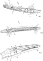
- a bumper beam 10 is shown in a perspective view from the front side with a mounting bracket.
- the same bumper beam 10 is shown in a perspective view from the inside, i.e. the side arranged to face the vehicle.
- the bumper beam 10 comprises an elongate main cross member 11 produced of a bent plate, wherein the main cross member 11 comprises an elongate bottom portion 12 with two elongate web portions 13,14 on either side thereof.
- An upper elongate web portion 13 is arranged above the elongate bottom portion 12, and a lower elongate lower web portion 14 is arranged below the same, wherein the elongate bottom portion 12 and elongate web portions 13,14 are arranged to extend horizontally, when arranged on a vehicle, over at least a first length L1.
- the first length L1 corresponds to the length between two spaced apart attachment sections 16 for attaching the bumper beam 10 to two spaced apart attachment portions on a vehicle, e.g. via mounting brackets or crash boxes.
- the mounting brackets 17 are arranged to connect the bumper beam 10 to the main body of the car (not shown).
- the upper and lower elongate lower web portions 13 and 14 extend outwards above and below the bottom portion 12, respectively, away from the vehicle when arranged on said vehicle.
- a cover plate 27 is preferably attached to the front side of the main cross member 11, to cover the gap formed between the two elongate web portions 13,14. The cover plate also contributes to a better performance of the bumper beam in a collision.
- a patch 15 is arranged along the elongate bottom portion 12.
- the patch 15 is arranged to cover a region that extends horizontally from each attachment section 16 and along the first length L1 between two spaced apart attachment sections 16. The presence of the patch 15 close to attachment section 16 will increase the ductility of the bumper beam in this critical area and drastically decrease the risk of rupture of the bumper beam in a collision with an impact zone just inside one of the attachment sections 16.
- the bottom portion 12 is wider at and around the attachment sections 16, than in the elongate portion between the attachment sections 16.
- the width of the patch 15 is adapted to width of the elongate bottom portion 12 of the crossmember such that it is wider at and around the attachment sections 16.
- the patch 15 is arranged on the back side of the bottom portion 12, arranged to face the vehicle when arranged on said vehicle. It may however also be provided on the front side of the bottom portion 12.
- the patch 15 extends along a full first length L1 between two spaced apart attachment sections 16. This is advantageous as it provides a non-broken ductile reinforcement. Further, the patch 15 extends along over the whole portion of the attachment section 16. This is advantageous as it presents a complement to the attachment between the patch and the cross member. Horizontally, the patch 15 extends over the whole of the attachment section 16.
- the patch 15 is arranged horizontally over the elongate bottom portion 12 and may also be arranged to extend vertically over at least a part of at least one web portion 13,14.
- the patch 15 may be arranged to extend over both transitions between the bottom portion 12 to the web portions 13,14, and into a part of said web portions 13 and 14. Also in a not shown embodiment, they extend vertically over one web portion or both web portions only at a region close to the attachment sections 16.
- the patch 15 comprises a circular opening 18 in line with one of the attachment sections 16 for attachment of tow hook.
- a tow hook tube 20 is welded inside said circular opening 18.
- the mounting bracket 17 comprises a corresponding opening for allowing passage of the tow hook tube 20.
- the patch 15 comprises guide holes 19 for guiding and positioning of the patch during production.
- the mounting bracket 17 comprises two openings 21 and 22, which are arranged to allow the mounting bracket 17 to be attached to the bumper beam, e.g. by means of welding or soldering.
- Welds such as point welds, LASER-welds or the like are provided around the contours of the openings 21 and 22.
- the welds may be provided around parts of the openings 21 and 22 or around the whole contour thereof.
- a weld may be provided along the sides 23 and 24 of the mounting bracket 17.
- a weld is preferable provided along the outer side 23 of the mounting bracket 17. It may be advantageous not to provide a weld along the inner side 24 of the mounting bracket 17 as this is a delicate zone where a heat affected zone or the like from a weld could have a negative effect on the performance of the bumper beam.
- FIG. 5 An alternative way mounting the inventive bumper beam 10 to a vehicle is shown in figure 5 , in which the bumper beam is attached to crash boxes 25 that in turn are connect the body of the vehicle.
- the bumper beam 10 may be welded to each crash box 25 by means of an outer weld 23 between the outer side of the crash box 23 and the patch 15.
- an upper and/or lower weld 26 may be provided between an upper or lower portion of the crash box 25 and the upper and lower elongate web portions 13 and 14, respectively.
- Such a weld 26 may hence advantageously be arranged on both sides of the crash box along the upper elongate web portion 13 and/or on both sides the lower elongate web portion 14 (not shown).
- the crash box 25 is preferably designed to enclose the shape of the bumper beam, with recesses on both sides to allow insertion of the bumper beam.
- the patch is preferably a steel plate, which preferably is attached to the bumper beam by welding.
- the patch is welded to a flat blank, which is subsequently press hardened together with the patch. It is advantageous to harden the bumper with the welded patch as such a procedure allows the welds to harden with both the patch and the main cross member, such that the negative effect of any heat affected zones (HAZ) is neutralized. Further, it is advantageous to press harden the patch together with the main cross member as it allows the patch to smoothly follow the contour of the main cross member.
- the patch is advantageously made of a steel blank with a greater thickness than the main cross member. The greater thickness is advantageous both as it provides more strength to the construction, but also as it presents a better support for the welds, for welding the bumper beam to mounting brackets 17 or the crash boxes 25.
- the patch may also be made of fibre reinforced polymer, e.g. CFRP, in which case it is attached to the bumper beam by means of an adhesive, after press hardening of the main cross member. If a patch of fibre reinforced polymer is used, the mounting brackets 17 or crash boxes 25 need to be fastened directly to the main cross member. Holes may be provided in the patch of fibre reinforced polymer to allow said bracket or crash box to be welded to main cross member.
- CFRP fibre reinforced polymer
Landscapes
- Engineering & Computer Science (AREA)
- Mechanical Engineering (AREA)
- Body Structure For Vehicles (AREA)
- Vibration Dampers (AREA)
Description
- The invention relates to a bumper beam. Specifically, the invention relates to such a bumper beam with a reinforcement arranged to increase the ductility of the bumper beam and to improve performance in bumper-to-bumper collisions that is off-set in the sideways direction.
- Bumper beams are used on vehicles, such as cars, to absorb the major portion of the forces in a frontal collision. Normally a bumper beam is arranged both in the front and in the rear of a vehicle.
- In the design and construction of bumper beams there is always a compromise between weight and strength. An advantageous manner of obtaining a good compromise is to provide a bumper beam from a steel plate that is formed into an advantageous shape, typically a hat-profile.
- Further, a bumper beam needs to be adapted to withstand different type of collisions. In the testing of the safety of a vehicle, such as a NCAP testing, the vehicle is subjected to a number of different collision tests. One such test that is of particular interest in the US is known in the art as FMVSS301 and is a bumper-to-bumper collision that is off-set in the sideways direction. Such collision will have a high impact force between the crash boxes and in unfavourable cases the bumper beam may rupture or come loose from the attachment point to the crash box
- Therefore, there is a need of a bumper beam with an improved performance in bumper-to-bumper collisions that is off-set in the sideways direction
- The document
US 2017/036623 A1 discloses a bumper beam according to the preamble of claim 1. - It is an object of the present invention to provide a bumper beam with improved performance in collisions, especially collisions with an impact zone horizontally just inside of the crash box.
- The invention relates to a bumper beam to be arranged horizontally on a motor vehicle, the bumper beam comprising an elongate main cross member produced of a bent plate, wherein the main cross member comprises an elongate bottom portion with two elongate web portions on either side thereof, said elongate bottom portion and elongate web portions being arranged to extend horizontally, when arranged on a vehicle, over at least a first length between two spaced apart attachment sections for attaching the bumper beam to two spaced apart attachment portions on the vehicle, and wherein the web portions are arranged above and below the bottom portion to extend outwards, away from the vehicle when arranged on said vehicle. A patch is arranged along the elongate bottom portion to cover a region that extends horizontally from each attachment section and along at least a section of the first length between two spaced apart attachment sections.
- With the arrangement according to the invention an increased performance is achieved in collisions with an impact zone at a region that extends horizontally inwards from each attachment section.
- Other embodiments and advantages will be apparent from the detailed description and the dependent claims.
- An exemplary embodiment related to the invention will now be described with reference to the appended drawings, of which;
- Fig. 1
- is a perspective view of a bumper beam with a mounting bracket viewed from the front side,
- Fig. 2
- is a perspective view of a bumper beam with a mounting bracket viewed from the inside,
- Fig. 3
- is a perspective view of a bumper beam viewed from the inside,
- Fig. 4
- is a detailed view of the bumper beam in
fig. 3 ; - Fig. 5
- is a detailed view of a bumper beam arranged on a crash box.
- In
Fig. 1 abumper beam 10 is shown in a perspective view from the front side with a mounting bracket. InFig. 2 thesame bumper beam 10 is shown in a perspective view from the inside, i.e. the side arranged to face the vehicle. - The
bumper beam 10 comprises an elongatemain cross member 11 produced of a bent plate, wherein themain cross member 11 comprises anelongate bottom portion 12 with twoelongate web portions elongate web portion 13 is arranged above theelongate bottom portion 12, and a lower elongatelower web portion 14 is arranged below the same, wherein theelongate bottom portion 12 andelongate web portions attachment sections 16 for attaching thebumper beam 10 to two spaced apart attachment portions on a vehicle, e.g. via mounting brackets or crash boxes. Infigures 1 and 2 themounting brackets 17 are arranged to connect thebumper beam 10 to the main body of the car (not shown). - The upper and lower elongate
lower web portions bottom portion 12, respectively, away from the vehicle when arranged on said vehicle. As is apparent infig. 1 acover plate 27 is preferably attached to the front side of themain cross member 11, to cover the gap formed between the twoelongate web portions - In accordance with the invention a
patch 15 is arranged along theelongate bottom portion 12. Thepatch 15 is arranged to cover a region that extends horizontally from eachattachment section 16 and along the first length L1 between two spaced apartattachment sections 16. The presence of thepatch 15 close toattachment section 16 will increase the ductility of the bumper beam in this critical area and drastically decrease the risk of rupture of the bumper beam in a collision with an impact zone just inside one of theattachment sections 16. - As is apparent in the figures, the
bottom portion 12 is wider at and around theattachment sections 16, than in the elongate portion between theattachment sections 16. Also, in the shown embodiment, the width of thepatch 15 is adapted to width of theelongate bottom portion 12 of the crossmember such that it is wider at and around theattachment sections 16. - According to the invention, the
patch 15 is arranged on the back side of thebottom portion 12, arranged to face the vehicle when arranged on said vehicle. It may however also be provided on the front side of thebottom portion 12. Thepatch 15 extends along a full first length L1 between two spaced apartattachment sections 16. This is advantageous as it provides a non-broken ductile reinforcement. Further, thepatch 15 extends along over the whole portion of theattachment section 16. This is advantageous as it presents a complement to the attachment between the patch and the cross member. Horizontally, thepatch 15 extends over the whole of theattachment section 16. - The
patch 15 is arranged horizontally over theelongate bottom portion 12 and may also be arranged to extend vertically over at least a part of at least oneweb portion patch 15 may be arranged to extend over both transitions between thebottom portion 12 to theweb portions web portions attachment sections 16. - In the shown embodiment, the
patch 15 comprises acircular opening 18 in line with one of theattachment sections 16 for attachment of tow hook. In the embodiment shown infigures 2 and4 , atow hook tube 20 is welded inside saidcircular opening 18. Themounting bracket 17 comprises a corresponding opening for allowing passage of thetow hook tube 20. Further, thepatch 15 comprisesguide holes 19 for guiding and positioning of the patch during production. - As is apparent from
fig. 4 , themounting bracket 17 comprises twoopenings 21 and 22, which are arranged to allow themounting bracket 17 to be attached to the bumper beam, e.g. by means of welding or soldering. Welds, such as point welds, LASER-welds or the like are provided around the contours of theopenings 21 and 22. The welds may be provided around parts of theopenings 21 and 22 or around the whole contour thereof. Further a weld may be provided along thesides mounting bracket 17. Specifically, a weld is preferable provided along theouter side 23 of the mountingbracket 17. It may be advantageous not to provide a weld along theinner side 24 of the mountingbracket 17 as this is a delicate zone where a heat affected zone or the like from a weld could have a negative effect on the performance of the bumper beam. - An alternative way mounting the
inventive bumper beam 10 to a vehicle is shown infigure 5 , in which the bumper beam is attached to crashboxes 25 that in turn are connect the body of the vehicle. Thebumper beam 10 may be welded to eachcrash box 25 by means of anouter weld 23 between the outer side of thecrash box 23 and thepatch 15. Further, an upper and/orlower weld 26 may be provided between an upper or lower portion of thecrash box 25 and the upper and lowerelongate web portions weld 26 may hence advantageously be arranged on both sides of the crash box along the upperelongate web portion 13 and/or on both sides the lower elongate web portion 14 (not shown). Thecrash box 25 is preferably designed to enclose the shape of the bumper beam, with recesses on both sides to allow insertion of the bumper beam. - The patch is preferably a steel plate, which preferably is attached to the bumper beam by welding. In an advantageous method of producing the bumper beam with attached patch, the patch is welded to a flat blank, which is subsequently press hardened together with the patch. It is advantageous to harden the bumper with the welded patch as such a procedure allows the welds to harden with both the patch and the main cross member, such that the negative effect of any heat affected zones (HAZ) is neutralized. Further, it is advantageous to press harden the patch together with the main cross member as it allows the patch to smoothly follow the contour of the main cross member. The patch is advantageously made of a steel blank with a greater thickness than the main cross member. The greater thickness is advantageous both as it provides more strength to the construction, but also as it presents a better support for the welds, for welding the bumper beam to mounting
brackets 17 or thecrash boxes 25. - The patch may also be made of fibre reinforced polymer, e.g. CFRP, in which case it is attached to the bumper beam by means of an adhesive, after press hardening of the main cross member. If a patch of fibre reinforced polymer is used, the mounting
brackets 17 orcrash boxes 25 need to be fastened directly to the main cross member. Holes may be provided in the patch of fibre reinforced polymer to allow said bracket or crash box to be welded to main cross member. - Above, the invention has been described with reference to specific embodiments. The invention is however not limited to these embodiments. It is obvious to a person skilled in the art that other embodiments are possible within the scope of the following claims.
Claims (4)
- A bumper beam (10) to be arranged horizontally on a motor vehicle, the bumper beam comprising an elongate main cross member (11) produced of a bent plate, wherein the main cross member (11) comprises an elongate bottom portion (12) with two elongate web portions (13,14) on either side thereof, said elongate bottom portion (12) and elongate web portions (13,14) being arranged to extend horizontally, when arranged on a vehicle, over at least a first length (L1) between two spaced apart attachment sections (16) for attaching the bumper beam (10) to two spaced apart attachment sections of vehicle, and wherein the web portions (13,14) are arranged above and below the bottom portion (12) to extend outwards, away from the vehicle when arranged on said vehicle, wherein a patch (15) is arranged along the elongate bottom portion (12) to cover a region that extends horizontally from each attachment section (16), which patch (15) is arranged to extend along the full first length (L1) between two spaced apart attachment sections (16), wherein the patch (15) horizontally extends over the whole of the attachment section (16),
characterized in that the patch (15) is arranged at the back side of the bottom portion (12), arranged to face the vehicle when arranged on said vehicle. - The bumper beam (10) according to claim 1, wherein the patch (15) comprises attachment means (18,19) in both attachment sections (16) for attachment to mounting brackets (17) or crash boxes (25).
- The bumper beam (10) according to anyone of the claims 1 or 2, wherein the patch (15) is a steel plate.
- The bumper beam (10) according to anyone of the claims 1 or 2, wherein the patch (15) is a plate made of fibre reinforced polymer.
Applications Claiming Priority (2)
| Application Number | Priority Date | Filing Date | Title |
|---|---|---|---|
| SE1750635A SE1750635A1 (en) | 2017-05-22 | 2017-05-22 | Bumper beam with reinforcement patch |
| PCT/EP2018/061693 WO2018215194A1 (en) | 2017-05-22 | 2018-05-07 | Bumper beam with reinforcement patch |
Publications (2)
| Publication Number | Publication Date |
|---|---|
| EP3630551A1 EP3630551A1 (en) | 2020-04-08 |
| EP3630551B1 true EP3630551B1 (en) | 2021-02-17 |
Family
ID=62186413
Family Applications (1)
| Application Number | Title | Priority Date | Filing Date |
|---|---|---|---|
| EP18725141.8A Active EP3630551B1 (en) | 2017-05-22 | 2018-05-07 | Bumper beam with reinforcement patch |
Country Status (8)
| Country | Link |
|---|---|
| US (1) | US11142152B2 (en) |
| EP (1) | EP3630551B1 (en) |
| JP (1) | JP2020520847A (en) |
| KR (1) | KR20200010419A (en) |
| CN (1) | CN110709285B (en) |
| ES (1) | ES2863464T3 (en) |
| SE (1) | SE1750635A1 (en) |
| WO (1) | WO2018215194A1 (en) |
Families Citing this family (6)
| Publication number | Priority date | Publication date | Assignee | Title |
|---|---|---|---|---|
| DE102015117700A1 (en) * | 2015-10-16 | 2017-04-20 | Magna International Inc. | Cross member and method for producing a cross member |
| DE102019105188A1 (en) * | 2019-02-28 | 2020-09-03 | Böllhoff Verbindungstechnik GmbH | Impact protection reinforcement of a vehicle structure and connection and manufacturing processes therefor |
| DE102019108907B4 (en) * | 2019-04-04 | 2021-06-02 | Benteler Automobiltechnik Gmbh | Bumper arrangement with clinched mount |
| JP7358307B2 (en) * | 2020-08-11 | 2023-10-10 | 豊田鉄工株式会社 | Structural components for vehicles |
| EP4144594A1 (en) * | 2021-09-03 | 2023-03-08 | Autotech Engineering S.L. | Crash bracket and bumper beam comprising such crash bracket |
| PT4419395T (en) * | 2021-10-20 | 2025-10-28 | Autotech Eng Sl | Bumper beam |
Citations (2)
| Publication number | Priority date | Publication date | Assignee | Title |
|---|---|---|---|---|
| CN101372212A (en) * | 2007-08-24 | 2009-02-25 | 比亚迪股份有限公司 | Anti-collision bar of vehicle and anti-collision device including the anti-collision bar |
| US20170036623A1 (en) * | 2015-08-07 | 2017-02-09 | Toyoda Iron Works Co., Ltd | Bumper reinforcement |
Family Cites Families (61)
| Publication number | Priority date | Publication date | Assignee | Title |
|---|---|---|---|---|
| US4397490A (en) * | 1981-05-04 | 1983-08-09 | Ford Motor Company | Low profile bumper |
| US5154462A (en) * | 1991-12-23 | 1992-10-13 | Ford Motor Company | Method for making a bonded vehicular cross member bumper beam from two materials |
| FR2763547A1 (en) * | 1997-05-23 | 1998-11-27 | Plastic Omnium Cie | BUMPER WITH LOCAL ABSORBER |
| JP4186249B2 (en) * | 1998-03-05 | 2008-11-26 | マツダ株式会社 | Bumper structure of vehicle |
| US6998174B2 (en) * | 2000-02-24 | 2006-02-14 | Conix Corporation | Integrated co-injection molded vehicle components and methods of making the same |
| DE10013527A1 (en) * | 2000-03-20 | 2001-10-11 | Benteler Werke Ag | Steel transverse bumper (fender) cross-bearer making process involves joining narrow strips into bonded element and deforming it by roll deforming process |
| JP2002240658A (en) * | 2001-02-15 | 2002-08-28 | Toray Ind Inc | Metal / FRP shock absorbing member |
| JP2003129611A (en) * | 2001-08-01 | 2003-05-08 | Kobe Steel Ltd | Bending strength member |
| AU2003248628A1 (en) * | 2002-06-06 | 2003-12-22 | Netshape Corp | Bumper with integrated energy absorber and beam |
| FR2847868B1 (en) * | 2002-11-29 | 2005-03-18 | Plastic Omnium Cie | BEAM HULL AND METAL REINFORCED BEAM |
| JP4423018B2 (en) * | 2003-11-27 | 2010-03-03 | スズキ株式会社 | Bumper beam assembly |
| JP2006036082A (en) * | 2004-07-28 | 2006-02-09 | Honda Motor Co Ltd | Bumper structure for vehicles |
| US7086690B2 (en) * | 2004-08-24 | 2006-08-08 | General Electric Company | Bumper assembly including twin energy absorbers |
| JP4425771B2 (en) * | 2004-12-16 | 2010-03-03 | 株式会社オーツカ | Impact energy absorbing material and impact energy absorbing structure |
| US7278667B2 (en) * | 2005-05-23 | 2007-10-09 | General Electric Company | Bumper assembly with energy absorber |
| US20070120383A1 (en) * | 2005-10-26 | 2007-05-31 | Meridian Automotive Systems, Inc. | Bumper system |
| US20070176442A1 (en) * | 2006-01-30 | 2007-08-02 | Nissan Technical Center North America, Inc. | Bumper stay |
| JP5040568B2 (en) * | 2007-10-01 | 2012-10-03 | マツダ株式会社 | Auto body structure |
| US8215686B2 (en) * | 2007-12-31 | 2012-07-10 | Sabic Innovative Plastics Ip B.V. | Fascia energy absorber, bumper system and process |
| US8016331B2 (en) * | 2008-02-14 | 2011-09-13 | Shape Corp. | Energy absorber with sidewall stabilizer ribs |
| US20100102580A1 (en) * | 2008-10-23 | 2010-04-29 | Brooks Ryan J | Energy absorber with differentiating angled walls |
| US9610910B2 (en) * | 2009-06-30 | 2017-04-04 | Gestamp Hardtech Ab | Bumper for a vehicle |
| FR2952329B1 (en) * | 2009-11-12 | 2013-11-29 | Faurecia Bloc Avant | FRONT ASSEMBLY OF A MOTOR VEHICLE COMPRISING A FRONT BUMPER SHIELD CONTAINING MEANS FOR FASTENING AT LEAST ONE AUXILIARY EQUIPMENT OF THE MOTOR VEHICLE |
| JP5444029B2 (en) * | 2010-02-08 | 2014-03-19 | 株式会社神戸製鋼所 | Method for manufacturing composite reinforcing member and composite reinforcing member |
| JP2011195125A (en) * | 2010-03-24 | 2011-10-06 | Aisin Takaoka Ltd | Method for manufacturing vehicle component |
| US8646552B2 (en) * | 2010-07-21 | 2014-02-11 | Shape Corp. | Integrated energy absorber and air flow management structure |
| JP5741041B2 (en) * | 2011-02-14 | 2015-07-01 | マツダ株式会社 | Crush can made of die-cast aluminum alloy |
| JP5548227B2 (en) * | 2012-03-29 | 2014-07-16 | 本田技研工業株式会社 | Bumper structure |
| EP2930068B1 (en) * | 2012-12-07 | 2017-10-18 | Toyota Jidosha Kabushiki Kaisha | Vehicle body end structure |
| SE537087C2 (en) * | 2013-03-13 | 2014-12-30 | Gestamp Hardtech Ab | Bumper beam |
| SE537112C2 (en) * | 2013-03-13 | 2015-01-20 | Gestamp Hardtech Ab | Bumper beam with mounting plates |
| JP5969417B2 (en) * | 2013-03-25 | 2016-08-17 | 富士重工業株式会社 | Body front structure |
| JP5979084B2 (en) * | 2013-06-05 | 2016-08-24 | トヨタ自動車株式会社 | Body front structure |
| KR101484227B1 (en) * | 2013-07-09 | 2015-01-21 | 현대자동차 주식회사 | Hybrid bumper beam for vehicles and manufacturing method thereof and bumper beam unit for vehicles using this |
| US9505361B2 (en) * | 2013-10-04 | 2016-11-29 | Multimatic Inc. | Vehicle bumper |
| WO2015079876A1 (en) * | 2013-11-27 | 2015-06-04 | 本田技研工業株式会社 | Automobile bumper |
| US9884597B2 (en) * | 2014-04-28 | 2018-02-06 | Shape Corp. | Multi-strip beam-forming apparatus, method, and beam |
| US10407011B2 (en) * | 2014-07-09 | 2019-09-10 | Magna International Inc. | Cast bumper system and method of manufacturing same |
| JP6482833B2 (en) * | 2014-11-21 | 2019-03-13 | アイシン精機株式会社 | Bumper device for vehicle |
| US9527464B2 (en) * | 2014-11-25 | 2016-12-27 | Toyota Motor Engineering & Manufacturing North America, Inc. | Bumpers including a reinforcement bracket and vehicles incorporating the same |
| US9758118B2 (en) * | 2014-11-26 | 2017-09-12 | Toyota Motor Engineering & Manufacturing North America, Inc. | Bumpers including energy diverting bumper structures and vehicles incorporating the same |
| WO2016089989A1 (en) * | 2014-12-05 | 2016-06-09 | Shape Corp. | Beam incorporating aluminum extrusion and long-fiber reinforced plastic |
| US9682674B2 (en) * | 2014-12-11 | 2017-06-20 | Shape Corp. | Pultruded beam, and apparatus and methods for manufacturing |
| US9358941B1 (en) * | 2015-01-22 | 2016-06-07 | Toyota Motor Engineering & Manufacturing North America, Inc. | Bumpers including a reinforcement patch and vehicles incorporating the same |
| JP6179537B2 (en) * | 2015-02-24 | 2017-08-16 | トヨタ自動車株式会社 | Bumper reinforcement structure for vehicles |
| WO2016152374A1 (en) * | 2015-03-24 | 2016-09-29 | 帝人株式会社 | Resin structure and vehicle components |
| KR101776389B1 (en) * | 2015-07-28 | 2017-09-20 | 현대자동차주식회사 | Bumper unit of vehicle and method for producing the same |
| JP6137707B2 (en) * | 2015-08-03 | 2017-05-31 | 本田技研工業株式会社 | Manufacturing method of bumper beam for automobile |
| US10351175B2 (en) * | 2015-10-01 | 2019-07-16 | Benteler Automobiltechnik Gmbh | Motor vehicle hybrid structural part |
| US9902349B2 (en) * | 2016-03-22 | 2018-02-27 | Ford Global Technologies, Llc | Vehicle bumper assembly |
| WO2018091948A1 (en) * | 2016-11-18 | 2018-05-24 | Arcelormittal | Bumper beam having an 8 shaped cross-section |
| WO2018091947A1 (en) * | 2016-11-18 | 2018-05-24 | Arcelormittal | Bumper beam having ribs on several walls of the bumper beam |
| US20180265023A1 (en) * | 2017-03-20 | 2018-09-20 | Ford Global Technologies, Llc. | Additively manufactured lattice core for energy absorbers adaptable to different impact load cases |
| JP6406484B1 (en) * | 2017-03-23 | 2018-10-17 | 新日鐵住金株式会社 | Bumper beam |
| FR3066737B1 (en) * | 2017-05-29 | 2020-09-04 | Peugeot Citroen Automobiles Sa | FRONT PART OF THE BODY OF A VEHICLE WITH SIDE REINFORCEMENTS IN THE EVENT OF FRONTAL IMPACT AGAINST ANOTHER VEHICLE |
| JP7072389B2 (en) * | 2018-01-15 | 2022-05-20 | 株式会社神戸製鋼所 | Vehicle structure and its manufacturing method |
| US10618483B2 (en) * | 2018-01-31 | 2020-04-14 | GM Global Technology Operations LLC | Multi-component composite energy-absorbing structure having a corrugated joint |
| JP2019214289A (en) * | 2018-06-12 | 2019-12-19 | 本田技研工業株式会社 | Vehicle front structure |
| JP6672387B2 (en) * | 2018-06-27 | 2020-03-25 | 本田技研工業株式会社 | Body front structure |
| KR102586916B1 (en) * | 2018-07-16 | 2023-10-10 | 현대자동차주식회사 | Ultralight front end module with lower memberless |
| JP7014116B2 (en) * | 2018-09-26 | 2022-02-01 | マツダ株式会社 | Body structure |
-
2017
- 2017-05-22 SE SE1750635A patent/SE1750635A1/en not_active Application Discontinuation
-
2018
- 2018-05-07 US US16/605,581 patent/US11142152B2/en active Active
- 2018-05-07 CN CN201880033538.9A patent/CN110709285B/en active Active
- 2018-05-07 KR KR1020197037707A patent/KR20200010419A/en not_active Withdrawn
- 2018-05-07 ES ES18725141T patent/ES2863464T3/en active Active
- 2018-05-07 JP JP2019564520A patent/JP2020520847A/en active Pending
- 2018-05-07 WO PCT/EP2018/061693 patent/WO2018215194A1/en not_active Ceased
- 2018-05-07 EP EP18725141.8A patent/EP3630551B1/en active Active
Patent Citations (2)
| Publication number | Priority date | Publication date | Assignee | Title |
|---|---|---|---|---|
| CN101372212A (en) * | 2007-08-24 | 2009-02-25 | 比亚迪股份有限公司 | Anti-collision bar of vehicle and anti-collision device including the anti-collision bar |
| US20170036623A1 (en) * | 2015-08-07 | 2017-02-09 | Toyoda Iron Works Co., Ltd | Bumper reinforcement |
Also Published As
| Publication number | Publication date |
|---|---|
| KR20200010419A (en) | 2020-01-30 |
| EP3630551A1 (en) | 2020-04-08 |
| SE1750635A1 (en) | 2018-11-23 |
| JP2020520847A (en) | 2020-07-16 |
| US20200122663A1 (en) | 2020-04-23 |
| ES2863464T3 (en) | 2021-10-11 |
| CN110709285B (en) | 2023-06-30 |
| CN110709285A (en) | 2020-01-17 |
| WO2018215194A1 (en) | 2018-11-29 |
| US11142152B2 (en) | 2021-10-12 |
Similar Documents
| Publication | Publication Date | Title |
|---|---|---|
| EP3630551B1 (en) | Bumper beam with reinforcement patch | |
| US11987192B2 (en) | Bumper cross beam for a motor vehicle | |
| KR102697404B1 (en) | Bumper Crossmember for Vehicle | |
| US10501036B2 (en) | Bumper reinforcement | |
| US10053152B2 (en) | Sill for a vehicle | |
| EP3386841B1 (en) | Vehicle rear body structure and method for manufacturing thereof | |
| CN108367786B (en) | Vehicle front body structure and method for manufacturing same | |
| KR102513658B1 (en) | Bumper beam with insert | |
| JP7165814B2 (en) | Bumper beam with steel reinforcement | |
| JP6546169B2 (en) | Car body | |
| US10077075B2 (en) | Vehicle lower section structure | |
| EP3386847B1 (en) | Vehicle underbody structure comprising a reinforcement element between a longitudinal beam and a lowerside sill part | |
| CN106828375B (en) | Front collision crossbeam | |
| US20240359649A1 (en) | Bumper Crossmember For A Vehicle | |
| KR20010059938A (en) | Method for making automotive bumper beam | |
| CN220163990U (en) | Front side member structure and vehicle | |
| JP2017013722A (en) | Bumper reinforcement | |
| KR102574008B1 (en) | Method for Manufacturing Automotive Structural Parts Including Underside Sills and Lower Front Pillars | |
| CN222329832U (en) | A-pillar outer panel structure, body-in-white and vehicle | |
| CN112638750B (en) | Motor vehicle front pillar structure | |
| WO2024154367A1 (en) | Skeleton structure for vehicle | |
| JP2024009642A (en) | Vehicles with impact beams | |
| JP2014101063A (en) | Collision safety structure of vehicle body frame |
Legal Events
| Date | Code | Title | Description |
|---|---|---|---|
| STAA | Information on the status of an ep patent application or granted ep patent |
Free format text: STATUS: UNKNOWN |
|
| STAA | Information on the status of an ep patent application or granted ep patent |
Free format text: STATUS: THE INTERNATIONAL PUBLICATION HAS BEEN MADE |
|
| PUAI | Public reference made under article 153(3) epc to a published international application that has entered the european phase |
Free format text: ORIGINAL CODE: 0009012 |
|
| STAA | Information on the status of an ep patent application or granted ep patent |
Free format text: STATUS: REQUEST FOR EXAMINATION WAS MADE |
|
| 17P | Request for examination filed |
Effective date: 20191010 |
|
| AK | Designated contracting states |
Kind code of ref document: A1 Designated state(s): AL AT BE BG CH CY CZ DE DK EE ES FI FR GB GR HR HU IE IS IT LI LT LU LV MC MK MT NL NO PL PT RO RS SE SI SK SM TR |
|
| AX | Request for extension of the european patent |
Extension state: BA ME |
|
| DAV | Request for validation of the european patent (deleted) | ||
| DAX | Request for extension of the european patent (deleted) | ||
| GRAP | Despatch of communication of intention to grant a patent |
Free format text: ORIGINAL CODE: EPIDOSNIGR1 |
|
| STAA | Information on the status of an ep patent application or granted ep patent |
Free format text: STATUS: GRANT OF PATENT IS INTENDED |
|
| INTG | Intention to grant announced |
Effective date: 20201002 |
|
| GRAS | Grant fee paid |
Free format text: ORIGINAL CODE: EPIDOSNIGR3 |
|
| GRAA | (expected) grant |
Free format text: ORIGINAL CODE: 0009210 |
|
| STAA | Information on the status of an ep patent application or granted ep patent |
Free format text: STATUS: THE PATENT HAS BEEN GRANTED |
|
| AK | Designated contracting states |
Kind code of ref document: B1 Designated state(s): AL AT BE BG CH CY CZ DE DK EE ES FI FR GB GR HR HU IE IS IT LI LT LU LV MC MK MT NL NO PL PT RO RS SE SI SK SM TR |
|
| REG | Reference to a national code |
Ref country code: GB Ref legal event code: FG4D |
|
| REG | Reference to a national code |
Ref country code: CH Ref legal event code: EP |
|
| REG | Reference to a national code |
Ref country code: SE Ref legal event code: TRGR |
|
| REG | Reference to a national code |
Ref country code: DE Ref legal event code: R096 Ref document number: 602018012718 Country of ref document: DE |
|
| REG | Reference to a national code |
Ref country code: AT Ref legal event code: REF Ref document number: 1361072 Country of ref document: AT Kind code of ref document: T Effective date: 20210315 |
|
| REG | Reference to a national code |
Ref country code: IE Ref legal event code: FG4D |
|
| REG | Reference to a national code |
Ref country code: LT Ref legal event code: MG9D |
|
| REG | Reference to a national code |
Ref country code: NL Ref legal event code: MP Effective date: 20210217 |
|
| PG25 | Lapsed in a contracting state [announced via postgrant information from national office to epo] |
Ref country code: LT Free format text: LAPSE BECAUSE OF FAILURE TO SUBMIT A TRANSLATION OF THE DESCRIPTION OR TO PAY THE FEE WITHIN THE PRESCRIBED TIME-LIMIT Effective date: 20210217 Ref country code: PT Free format text: LAPSE BECAUSE OF FAILURE TO SUBMIT A TRANSLATION OF THE DESCRIPTION OR TO PAY THE FEE WITHIN THE PRESCRIBED TIME-LIMIT Effective date: 20210617 Ref country code: NO Free format text: LAPSE BECAUSE OF FAILURE TO SUBMIT A TRANSLATION OF THE DESCRIPTION OR TO PAY THE FEE WITHIN THE PRESCRIBED TIME-LIMIT Effective date: 20210517 Ref country code: FI Free format text: LAPSE BECAUSE OF FAILURE TO SUBMIT A TRANSLATION OF THE DESCRIPTION OR TO PAY THE FEE WITHIN THE PRESCRIBED TIME-LIMIT Effective date: 20210217 Ref country code: GR Free format text: LAPSE BECAUSE OF FAILURE TO SUBMIT A TRANSLATION OF THE DESCRIPTION OR TO PAY THE FEE WITHIN THE PRESCRIBED TIME-LIMIT Effective date: 20210518 Ref country code: HR Free format text: LAPSE BECAUSE OF FAILURE TO SUBMIT A TRANSLATION OF THE DESCRIPTION OR TO PAY THE FEE WITHIN THE PRESCRIBED TIME-LIMIT Effective date: 20210217 Ref country code: BG Free format text: LAPSE BECAUSE OF FAILURE TO SUBMIT A TRANSLATION OF THE DESCRIPTION OR TO PAY THE FEE WITHIN THE PRESCRIBED TIME-LIMIT Effective date: 20210517 |
|
| REG | Reference to a national code |
Ref country code: AT Ref legal event code: MK05 Ref document number: 1361072 Country of ref document: AT Kind code of ref document: T Effective date: 20210217 |
|
| PG25 | Lapsed in a contracting state [announced via postgrant information from national office to epo] |
Ref country code: RS Free format text: LAPSE BECAUSE OF FAILURE TO SUBMIT A TRANSLATION OF THE DESCRIPTION OR TO PAY THE FEE WITHIN THE PRESCRIBED TIME-LIMIT Effective date: 20210217 Ref country code: PL Free format text: LAPSE BECAUSE OF FAILURE TO SUBMIT A TRANSLATION OF THE DESCRIPTION OR TO PAY THE FEE WITHIN THE PRESCRIBED TIME-LIMIT Effective date: 20210217 Ref country code: LV Free format text: LAPSE BECAUSE OF FAILURE TO SUBMIT A TRANSLATION OF THE DESCRIPTION OR TO PAY THE FEE WITHIN THE PRESCRIBED TIME-LIMIT Effective date: 20210217 Ref country code: NL Free format text: LAPSE BECAUSE OF FAILURE TO SUBMIT A TRANSLATION OF THE DESCRIPTION OR TO PAY THE FEE WITHIN THE PRESCRIBED TIME-LIMIT Effective date: 20210217 |
|
| PG25 | Lapsed in a contracting state [announced via postgrant information from national office to epo] |
Ref country code: IS Free format text: LAPSE BECAUSE OF FAILURE TO SUBMIT A TRANSLATION OF THE DESCRIPTION OR TO PAY THE FEE WITHIN THE PRESCRIBED TIME-LIMIT Effective date: 20210617 |
|
| REG | Reference to a national code |
Ref country code: ES Ref legal event code: FG2A Ref document number: 2863464 Country of ref document: ES Kind code of ref document: T3 Effective date: 20211011 |
|
| PG25 | Lapsed in a contracting state [announced via postgrant information from national office to epo] |
Ref country code: AT Free format text: LAPSE BECAUSE OF FAILURE TO SUBMIT A TRANSLATION OF THE DESCRIPTION OR TO PAY THE FEE WITHIN THE PRESCRIBED TIME-LIMIT Effective date: 20210217 Ref country code: SM Free format text: LAPSE BECAUSE OF FAILURE TO SUBMIT A TRANSLATION OF THE DESCRIPTION OR TO PAY THE FEE WITHIN THE PRESCRIBED TIME-LIMIT Effective date: 20210217 Ref country code: EE Free format text: LAPSE BECAUSE OF FAILURE TO SUBMIT A TRANSLATION OF THE DESCRIPTION OR TO PAY THE FEE WITHIN THE PRESCRIBED TIME-LIMIT Effective date: 20210217 Ref country code: CZ Free format text: LAPSE BECAUSE OF FAILURE TO SUBMIT A TRANSLATION OF THE DESCRIPTION OR TO PAY THE FEE WITHIN THE PRESCRIBED TIME-LIMIT Effective date: 20210217 |
|
| REG | Reference to a national code |
Ref country code: DE Ref legal event code: R097 Ref document number: 602018012718 Country of ref document: DE |
|
| PG25 | Lapsed in a contracting state [announced via postgrant information from national office to epo] |
Ref country code: SK Free format text: LAPSE BECAUSE OF FAILURE TO SUBMIT A TRANSLATION OF THE DESCRIPTION OR TO PAY THE FEE WITHIN THE PRESCRIBED TIME-LIMIT Effective date: 20210217 Ref country code: RO Free format text: LAPSE BECAUSE OF FAILURE TO SUBMIT A TRANSLATION OF THE DESCRIPTION OR TO PAY THE FEE WITHIN THE PRESCRIBED TIME-LIMIT Effective date: 20210217 Ref country code: DK Free format text: LAPSE BECAUSE OF FAILURE TO SUBMIT A TRANSLATION OF THE DESCRIPTION OR TO PAY THE FEE WITHIN THE PRESCRIBED TIME-LIMIT Effective date: 20210217 |
|
| PLBE | No opposition filed within time limit |
Free format text: ORIGINAL CODE: 0009261 |
|
| STAA | Information on the status of an ep patent application or granted ep patent |
Free format text: STATUS: NO OPPOSITION FILED WITHIN TIME LIMIT |
|
| REG | Reference to a national code |
Ref country code: CH Ref legal event code: PL |
|
| 26N | No opposition filed |
Effective date: 20211118 |
|
| PG25 | Lapsed in a contracting state [announced via postgrant information from national office to epo] |
Ref country code: LU Free format text: LAPSE BECAUSE OF NON-PAYMENT OF DUE FEES Effective date: 20210507 Ref country code: LI Free format text: LAPSE BECAUSE OF NON-PAYMENT OF DUE FEES Effective date: 20210531 Ref country code: MC Free format text: LAPSE BECAUSE OF FAILURE TO SUBMIT A TRANSLATION OF THE DESCRIPTION OR TO PAY THE FEE WITHIN THE PRESCRIBED TIME-LIMIT Effective date: 20210217 Ref country code: CH Free format text: LAPSE BECAUSE OF NON-PAYMENT OF DUE FEES Effective date: 20210531 Ref country code: AL Free format text: LAPSE BECAUSE OF FAILURE TO SUBMIT A TRANSLATION OF THE DESCRIPTION OR TO PAY THE FEE WITHIN THE PRESCRIBED TIME-LIMIT Effective date: 20210217 |
|
| REG | Reference to a national code |
Ref country code: BE Ref legal event code: MM Effective date: 20210531 |
|
| PG25 | Lapsed in a contracting state [announced via postgrant information from national office to epo] |
Ref country code: SI Free format text: LAPSE BECAUSE OF FAILURE TO SUBMIT A TRANSLATION OF THE DESCRIPTION OR TO PAY THE FEE WITHIN THE PRESCRIBED TIME-LIMIT Effective date: 20210217 |
|
| PG25 | Lapsed in a contracting state [announced via postgrant information from national office to epo] |
Ref country code: IT Free format text: LAPSE BECAUSE OF FAILURE TO SUBMIT A TRANSLATION OF THE DESCRIPTION OR TO PAY THE FEE WITHIN THE PRESCRIBED TIME-LIMIT Effective date: 20210217 Ref country code: IE Free format text: LAPSE BECAUSE OF NON-PAYMENT OF DUE FEES Effective date: 20210507 |
|
| PG25 | Lapsed in a contracting state [announced via postgrant information from national office to epo] |
Ref country code: IS Free format text: LAPSE BECAUSE OF FAILURE TO SUBMIT A TRANSLATION OF THE DESCRIPTION OR TO PAY THE FEE WITHIN THE PRESCRIBED TIME-LIMIT Effective date: 20210617 |
|
| PG25 | Lapsed in a contracting state [announced via postgrant information from national office to epo] |
Ref country code: BE Free format text: LAPSE BECAUSE OF NON-PAYMENT OF DUE FEES Effective date: 20210531 |
|
| PGFP | Annual fee paid to national office [announced via postgrant information from national office to epo] |
Ref country code: SE Payment date: 20220527 Year of fee payment: 5 Ref country code: GB Payment date: 20220527 Year of fee payment: 5 Ref country code: FR Payment date: 20220525 Year of fee payment: 5 |
|
| PG25 | Lapsed in a contracting state [announced via postgrant information from national office to epo] |
Ref country code: CY Free format text: LAPSE BECAUSE OF FAILURE TO SUBMIT A TRANSLATION OF THE DESCRIPTION OR TO PAY THE FEE WITHIN THE PRESCRIBED TIME-LIMIT Effective date: 20210217 |
|
| PG25 | Lapsed in a contracting state [announced via postgrant information from national office to epo] |
Ref country code: HU Free format text: LAPSE BECAUSE OF FAILURE TO SUBMIT A TRANSLATION OF THE DESCRIPTION OR TO PAY THE FEE WITHIN THE PRESCRIBED TIME-LIMIT; INVALID AB INITIO Effective date: 20180507 |
|
| REG | Reference to a national code |
Ref country code: SE Ref legal event code: EUG |
|
| GBPC | Gb: european patent ceased through non-payment of renewal fee |
Effective date: 20230507 |
|
| PG25 | Lapsed in a contracting state [announced via postgrant information from national office to epo] |
Ref country code: SE Free format text: LAPSE BECAUSE OF NON-PAYMENT OF DUE FEES Effective date: 20230508 |
|
| PG25 | Lapsed in a contracting state [announced via postgrant information from national office to epo] |
Ref country code: MK Free format text: LAPSE BECAUSE OF FAILURE TO SUBMIT A TRANSLATION OF THE DESCRIPTION OR TO PAY THE FEE WITHIN THE PRESCRIBED TIME-LIMIT Effective date: 20210217 Ref country code: GB Free format text: LAPSE BECAUSE OF NON-PAYMENT OF DUE FEES Effective date: 20230507 |
|
| PG25 | Lapsed in a contracting state [announced via postgrant information from national office to epo] |
Ref country code: FR Free format text: LAPSE BECAUSE OF NON-PAYMENT OF DUE FEES Effective date: 20230531 |
|
| PG25 | Lapsed in a contracting state [announced via postgrant information from national office to epo] |
Ref country code: MT Free format text: LAPSE BECAUSE OF FAILURE TO SUBMIT A TRANSLATION OF THE DESCRIPTION OR TO PAY THE FEE WITHIN THE PRESCRIBED TIME-LIMIT Effective date: 20210217 |
|
| PGFP | Annual fee paid to national office [announced via postgrant information from national office to epo] |
Ref country code: DE Payment date: 20250529 Year of fee payment: 8 |
|
| PGFP | Annual fee paid to national office [announced via postgrant information from national office to epo] |
Ref country code: ES Payment date: 20250602 Year of fee payment: 8 |
|
| PG25 | Lapsed in a contracting state [announced via postgrant information from national office to epo] |
Ref country code: TR Free format text: LAPSE BECAUSE OF FAILURE TO SUBMIT A TRANSLATION OF THE DESCRIPTION OR TO PAY THE FEE WITHIN THE PRESCRIBED TIME-LIMIT Effective date: 20210217 |