EP3630503B1 - Modular head assembly for an electric axle - Google Patents
Modular head assembly for an electric axle Download PDFInfo
- Publication number
- EP3630503B1 EP3630503B1 EP18731289.7A EP18731289A EP3630503B1 EP 3630503 B1 EP3630503 B1 EP 3630503B1 EP 18731289 A EP18731289 A EP 18731289A EP 3630503 B1 EP3630503 B1 EP 3630503B1
- Authority
- EP
- European Patent Office
- Prior art keywords
- gear
- assembly
- shaft
- axle
- housing
- Prior art date
- Legal status (The legal status is an assumption and is not a legal conclusion. Google has not performed a legal analysis and makes no representation as to the accuracy of the status listed.)
- Active
Links
- 230000000712 assembly Effects 0.000 claims description 71
- 238000000429 assembly Methods 0.000 claims description 71
- 241000538562 Banjos Species 0.000 claims description 35
- 230000007246 mechanism Effects 0.000 claims description 23
- 230000000087 stabilizing effect Effects 0.000 claims description 15
- 230000014759 maintenance of location Effects 0.000 claims description 5
- 230000000717 retained effect Effects 0.000 claims description 4
- 230000000670 limiting effect Effects 0.000 description 165
- 238000007789 sealing Methods 0.000 description 29
- 239000000853 adhesive Substances 0.000 description 28
- 230000001070 adhesive effect Effects 0.000 description 28
- 230000005540 biological transmission Effects 0.000 description 27
- 230000000295 complement effect Effects 0.000 description 27
- 230000008878 coupling Effects 0.000 description 14
- 238000010168 coupling process Methods 0.000 description 14
- 238000005859 coupling reaction Methods 0.000 description 14
- 241000239290 Araneae Species 0.000 description 12
- 230000005012 migration Effects 0.000 description 9
- 238000013508 migration Methods 0.000 description 9
- 238000002485 combustion reaction Methods 0.000 description 7
- 230000002829 reductive effect Effects 0.000 description 7
- 230000009467 reduction Effects 0.000 description 6
- 238000005096 rolling process Methods 0.000 description 5
- 239000000446 fuel Substances 0.000 description 4
- 238000004519 manufacturing process Methods 0.000 description 3
- 230000007704 transition Effects 0.000 description 3
- 230000008901 benefit Effects 0.000 description 2
- 230000005520 electrodynamics Effects 0.000 description 2
- 239000000463 material Substances 0.000 description 2
- 238000009825 accumulation Methods 0.000 description 1
- 230000008859 change Effects 0.000 description 1
- 238000004891 communication Methods 0.000 description 1
- 238000010276 construction Methods 0.000 description 1
- 230000001419 dependent effect Effects 0.000 description 1
- 238000007667 floating Methods 0.000 description 1
- 230000002401 inhibitory effect Effects 0.000 description 1
- 230000003137 locomotive effect Effects 0.000 description 1
- 238000000034 method Methods 0.000 description 1
- 230000004048 modification Effects 0.000 description 1
- 238000012986 modification Methods 0.000 description 1
- 238000004806 packaging method and process Methods 0.000 description 1
- 230000008569 process Effects 0.000 description 1
- 230000008439 repair process Effects 0.000 description 1
- 239000013598 vector Substances 0.000 description 1
Images


Classifications
-
- B—PERFORMING OPERATIONS; TRANSPORTING
- B60—VEHICLES IN GENERAL
- B60K—ARRANGEMENT OR MOUNTING OF PROPULSION UNITS OR OF TRANSMISSIONS IN VEHICLES; ARRANGEMENT OR MOUNTING OF PLURAL DIVERSE PRIME-MOVERS IN VEHICLES; AUXILIARY DRIVES FOR VEHICLES; INSTRUMENTATION OR DASHBOARDS FOR VEHICLES; ARRANGEMENTS IN CONNECTION WITH COOLING, AIR INTAKE, GAS EXHAUST OR FUEL SUPPLY OF PROPULSION UNITS IN VEHICLES
- B60K17/00—Arrangement or mounting of transmissions in vehicles
- B60K17/04—Arrangement or mounting of transmissions in vehicles characterised by arrangement, location, or kind of gearing
- B60K17/16—Arrangement or mounting of transmissions in vehicles characterised by arrangement, location, or kind of gearing of differential gearing
- B60K17/165—Arrangement or mounting of transmissions in vehicles characterised by arrangement, location, or kind of gearing of differential gearing provided between independent half axles
-
- B—PERFORMING OPERATIONS; TRANSPORTING
- B60—VEHICLES IN GENERAL
- B60B—VEHICLE WHEELS; CASTORS; AXLES FOR WHEELS OR CASTORS; INCREASING WHEEL ADHESION
- B60B35/00—Axle units; Parts thereof ; Arrangements for lubrication of axles
- B60B35/12—Torque-transmitting axles
- B60B35/14—Torque-transmitting axles composite or split, e.g. half- axles; Couplings between axle parts or sections
-
- B—PERFORMING OPERATIONS; TRANSPORTING
- B60—VEHICLES IN GENERAL
- B60B—VEHICLE WHEELS; CASTORS; AXLES FOR WHEELS OR CASTORS; INCREASING WHEEL ADHESION
- B60B35/00—Axle units; Parts thereof ; Arrangements for lubrication of axles
- B60B35/12—Torque-transmitting axles
- B60B35/16—Axle housings
-
- B—PERFORMING OPERATIONS; TRANSPORTING
- B60—VEHICLES IN GENERAL
- B60B—VEHICLE WHEELS; CASTORS; AXLES FOR WHEELS OR CASTORS; INCREASING WHEEL ADHESION
- B60B35/00—Axle units; Parts thereof ; Arrangements for lubrication of axles
- B60B35/12—Torque-transmitting axles
- B60B35/16—Axle housings
- B60B35/163—Axle housings characterised by specific shape of the housing, e.g. adaptations to give space for other vehicle elements like chassis or exhaust system
-
- B—PERFORMING OPERATIONS; TRANSPORTING
- B60—VEHICLES IN GENERAL
- B60K—ARRANGEMENT OR MOUNTING OF PROPULSION UNITS OR OF TRANSMISSIONS IN VEHICLES; ARRANGEMENT OR MOUNTING OF PLURAL DIVERSE PRIME-MOVERS IN VEHICLES; AUXILIARY DRIVES FOR VEHICLES; INSTRUMENTATION OR DASHBOARDS FOR VEHICLES; ARRANGEMENTS IN CONNECTION WITH COOLING, AIR INTAKE, GAS EXHAUST OR FUEL SUPPLY OF PROPULSION UNITS IN VEHICLES
- B60K1/00—Arrangement or mounting of electrical propulsion units
-
- B—PERFORMING OPERATIONS; TRANSPORTING
- B60—VEHICLES IN GENERAL
- B60K—ARRANGEMENT OR MOUNTING OF PROPULSION UNITS OR OF TRANSMISSIONS IN VEHICLES; ARRANGEMENT OR MOUNTING OF PLURAL DIVERSE PRIME-MOVERS IN VEHICLES; AUXILIARY DRIVES FOR VEHICLES; INSTRUMENTATION OR DASHBOARDS FOR VEHICLES; ARRANGEMENTS IN CONNECTION WITH COOLING, AIR INTAKE, GAS EXHAUST OR FUEL SUPPLY OF PROPULSION UNITS IN VEHICLES
- B60K17/00—Arrangement or mounting of transmissions in vehicles
- B60K17/34—Arrangement or mounting of transmissions in vehicles for driving both front and rear wheels, e.g. four wheel drive vehicles
- B60K17/344—Arrangement or mounting of transmissions in vehicles for driving both front and rear wheels, e.g. four wheel drive vehicles having a transfer gear
- B60K17/346—Arrangement or mounting of transmissions in vehicles for driving both front and rear wheels, e.g. four wheel drive vehicles having a transfer gear the transfer gear being a differential gear
-
- B—PERFORMING OPERATIONS; TRANSPORTING
- B60—VEHICLES IN GENERAL
- B60K—ARRANGEMENT OR MOUNTING OF PROPULSION UNITS OR OF TRANSMISSIONS IN VEHICLES; ARRANGEMENT OR MOUNTING OF PLURAL DIVERSE PRIME-MOVERS IN VEHICLES; AUXILIARY DRIVES FOR VEHICLES; INSTRUMENTATION OR DASHBOARDS FOR VEHICLES; ARRANGEMENTS IN CONNECTION WITH COOLING, AIR INTAKE, GAS EXHAUST OR FUEL SUPPLY OF PROPULSION UNITS IN VEHICLES
- B60K17/00—Arrangement or mounting of transmissions in vehicles
- B60K17/34—Arrangement or mounting of transmissions in vehicles for driving both front and rear wheels, e.g. four wheel drive vehicles
- B60K17/354—Arrangement or mounting of transmissions in vehicles for driving both front and rear wheels, e.g. four wheel drive vehicles having separate mechanical assemblies for transmitting drive to the front or to the rear wheels or set of wheels
-
- B—PERFORMING OPERATIONS; TRANSPORTING
- B60—VEHICLES IN GENERAL
- B60K—ARRANGEMENT OR MOUNTING OF PROPULSION UNITS OR OF TRANSMISSIONS IN VEHICLES; ARRANGEMENT OR MOUNTING OF PLURAL DIVERSE PRIME-MOVERS IN VEHICLES; AUXILIARY DRIVES FOR VEHICLES; INSTRUMENTATION OR DASHBOARDS FOR VEHICLES; ARRANGEMENTS IN CONNECTION WITH COOLING, AIR INTAKE, GAS EXHAUST OR FUEL SUPPLY OF PROPULSION UNITS IN VEHICLES
- B60K17/00—Arrangement or mounting of transmissions in vehicles
- B60K17/34—Arrangement or mounting of transmissions in vehicles for driving both front and rear wheels, e.g. four wheel drive vehicles
- B60K17/356—Arrangement or mounting of transmissions in vehicles for driving both front and rear wheels, e.g. four wheel drive vehicles having fluid or electric motor, for driving one or more wheels
-
- B—PERFORMING OPERATIONS; TRANSPORTING
- B60—VEHICLES IN GENERAL
- B60K—ARRANGEMENT OR MOUNTING OF PROPULSION UNITS OR OF TRANSMISSIONS IN VEHICLES; ARRANGEMENT OR MOUNTING OF PLURAL DIVERSE PRIME-MOVERS IN VEHICLES; AUXILIARY DRIVES FOR VEHICLES; INSTRUMENTATION OR DASHBOARDS FOR VEHICLES; ARRANGEMENTS IN CONNECTION WITH COOLING, AIR INTAKE, GAS EXHAUST OR FUEL SUPPLY OF PROPULSION UNITS IN VEHICLES
- B60K17/00—Arrangement or mounting of transmissions in vehicles
- B60K17/36—Arrangement or mounting of transmissions in vehicles for driving tandem wheels
-
- B—PERFORMING OPERATIONS; TRANSPORTING
- B60—VEHICLES IN GENERAL
- B60T—VEHICLE BRAKE CONTROL SYSTEMS OR PARTS THEREOF; BRAKE CONTROL SYSTEMS OR PARTS THEREOF, IN GENERAL; ARRANGEMENT OF BRAKING ELEMENTS ON VEHICLES IN GENERAL; PORTABLE DEVICES FOR PREVENTING UNWANTED MOVEMENT OF VEHICLES; VEHICLE MODIFICATIONS TO FACILITATE COOLING OF BRAKES
- B60T1/00—Arrangements of braking elements, i.e. of those parts where braking effect occurs specially for vehicles
- B60T1/02—Arrangements of braking elements, i.e. of those parts where braking effect occurs specially for vehicles acting by retarding wheels
- B60T1/06—Arrangements of braking elements, i.e. of those parts where braking effect occurs specially for vehicles acting by retarding wheels acting otherwise than on tread, e.g. employing rim, drum, disc, or transmission or on double wheels
- B60T1/062—Arrangements of braking elements, i.e. of those parts where braking effect occurs specially for vehicles acting by retarding wheels acting otherwise than on tread, e.g. employing rim, drum, disc, or transmission or on double wheels acting on transmission parts
-
- F—MECHANICAL ENGINEERING; LIGHTING; HEATING; WEAPONS; BLASTING
- F16—ENGINEERING ELEMENTS AND UNITS; GENERAL MEASURES FOR PRODUCING AND MAINTAINING EFFECTIVE FUNCTIONING OF MACHINES OR INSTALLATIONS; THERMAL INSULATION IN GENERAL
- F16H—GEARING
- F16H37/00—Combinations of mechanical gearings, not provided for in groups F16H1/00 - F16H35/00
- F16H37/02—Combinations of mechanical gearings, not provided for in groups F16H1/00 - F16H35/00 comprising essentially only toothed or friction gearings
- F16H37/06—Combinations of mechanical gearings, not provided for in groups F16H1/00 - F16H35/00 comprising essentially only toothed or friction gearings with a plurality of driving or driven shafts; with arrangements for dividing torque between two or more intermediate shafts
- F16H37/08—Combinations of mechanical gearings, not provided for in groups F16H1/00 - F16H35/00 comprising essentially only toothed or friction gearings with a plurality of driving or driven shafts; with arrangements for dividing torque between two or more intermediate shafts with differential gearing
-
- F—MECHANICAL ENGINEERING; LIGHTING; HEATING; WEAPONS; BLASTING
- F16—ENGINEERING ELEMENTS AND UNITS; GENERAL MEASURES FOR PRODUCING AND MAINTAINING EFFECTIVE FUNCTIONING OF MACHINES OR INSTALLATIONS; THERMAL INSULATION IN GENERAL
- F16H—GEARING
- F16H57/00—General details of gearing
- F16H57/02—Gearboxes; Mounting gearing therein
- F16H57/021—Shaft support structures, e.g. partition walls, bearing eyes, casing walls or covers with bearings
-
- F—MECHANICAL ENGINEERING; LIGHTING; HEATING; WEAPONS; BLASTING
- F16—ENGINEERING ELEMENTS AND UNITS; GENERAL MEASURES FOR PRODUCING AND MAINTAINING EFFECTIVE FUNCTIONING OF MACHINES OR INSTALLATIONS; THERMAL INSULATION IN GENERAL
- F16H—GEARING
- F16H57/00—General details of gearing
- F16H57/02—Gearboxes; Mounting gearing therein
- F16H57/029—Gearboxes; Mounting gearing therein characterised by means for sealing the gearboxes, e.g. to improve airtightness
-
- B—PERFORMING OPERATIONS; TRANSPORTING
- B60—VEHICLES IN GENERAL
- B60K—ARRANGEMENT OR MOUNTING OF PROPULSION UNITS OR OF TRANSMISSIONS IN VEHICLES; ARRANGEMENT OR MOUNTING OF PLURAL DIVERSE PRIME-MOVERS IN VEHICLES; AUXILIARY DRIVES FOR VEHICLES; INSTRUMENTATION OR DASHBOARDS FOR VEHICLES; ARRANGEMENTS IN CONNECTION WITH COOLING, AIR INTAKE, GAS EXHAUST OR FUEL SUPPLY OF PROPULSION UNITS IN VEHICLES
- B60K1/00—Arrangement or mounting of electrical propulsion units
- B60K2001/001—Arrangement or mounting of electrical propulsion units one motor mounted on a propulsion axle for rotating right and left wheels of this axle
-
- B—PERFORMING OPERATIONS; TRANSPORTING
- B60—VEHICLES IN GENERAL
- B60Y—INDEXING SCHEME RELATING TO ASPECTS CROSS-CUTTING VEHICLE TECHNOLOGY
- B60Y2200/00—Type of vehicle
- B60Y2200/10—Road Vehicles
- B60Y2200/14—Trucks; Load vehicles, Busses
- B60Y2200/142—Heavy duty trucks
- B60Y2200/1422—Multi-axle trucks
-
- B—PERFORMING OPERATIONS; TRANSPORTING
- B60—VEHICLES IN GENERAL
- B60Y—INDEXING SCHEME RELATING TO ASPECTS CROSS-CUTTING VEHICLE TECHNOLOGY
- B60Y2200/00—Type of vehicle
- B60Y2200/90—Vehicles comprising electric prime movers
- B60Y2200/91—Electric vehicles
-
- B—PERFORMING OPERATIONS; TRANSPORTING
- B60—VEHICLES IN GENERAL
- B60Y—INDEXING SCHEME RELATING TO ASPECTS CROSS-CUTTING VEHICLE TECHNOLOGY
- B60Y2200/00—Type of vehicle
- B60Y2200/90—Vehicles comprising electric prime movers
- B60Y2200/92—Hybrid vehicles
-
- F—MECHANICAL ENGINEERING; LIGHTING; HEATING; WEAPONS; BLASTING
- F16—ENGINEERING ELEMENTS AND UNITS; GENERAL MEASURES FOR PRODUCING AND MAINTAINING EFFECTIVE FUNCTIONING OF MACHINES OR INSTALLATIONS; THERMAL INSULATION IN GENERAL
- F16H—GEARING
- F16H48/00—Differential gearings
- F16H48/38—Constructional details
- F16H48/42—Constructional details characterised by features of the input shafts, e.g. mounting of drive gears thereon
- F16H2048/423—Constructional details characterised by features of the input shafts, e.g. mounting of drive gears thereon characterised by bearing arrangement
-
- F—MECHANICAL ENGINEERING; LIGHTING; HEATING; WEAPONS; BLASTING
- F16—ENGINEERING ELEMENTS AND UNITS; GENERAL MEASURES FOR PRODUCING AND MAINTAINING EFFECTIVE FUNCTIONING OF MACHINES OR INSTALLATIONS; THERMAL INSULATION IN GENERAL
- F16H—GEARING
- F16H57/00—General details of gearing
- F16H57/02—Gearboxes; Mounting gearing therein
- F16H2057/02034—Gearboxes combined or connected with electric machines
-
- F—MECHANICAL ENGINEERING; LIGHTING; HEATING; WEAPONS; BLASTING
- F16—ENGINEERING ELEMENTS AND UNITS; GENERAL MEASURES FOR PRODUCING AND MAINTAINING EFFECTIVE FUNCTIONING OF MACHINES OR INSTALLATIONS; THERMAL INSULATION IN GENERAL
- F16H—GEARING
- F16H57/00—General details of gearing
- F16H57/02—Gearboxes; Mounting gearing therein
- F16H2057/02039—Gearboxes for particular applications
- F16H2057/02043—Gearboxes for particular applications for vehicle transmissions
- F16H2057/02052—Axle units; Transfer casings for four wheel drive
Definitions
- the present invention relates to a modular electric axle head assembly for use in an electric vehicle and/or a hybrid electric vehicle.
- Hybrid vehicles typically use two or more distinct power sources to provide the power necessary to drive the vehicle.
- the electric drive axle assembly comprises an electrodynamic assembly and an axle housing assembly, wherein the electrodynamic assembly comprises a power motor, a transmission and a differential mechanism, the transmission comprises a transmission shell body, the power motor is fixed on the transmission shell body, and the differential mechanism is supported on the transmission shell body.
- CN 103 496 320 B relates to an integrated electric drive axle assembly, comprising a direct current motor controller, a direct current motor, a two-stage reduction gear assembly, an integrated type axle housing, a half axle and a brake drum.
- US 6 43 1 298 B1 relates to a vehicle drive unit assembly including a rear drive axle extending between a pair of vehicle wheels.
- An input shaft is operably connected to the drive axle to provide torque to the drive axle to drive the vehicle wheels.
- An electric motor is connected to the input shaft and is mounted above the drive axle. Preferably, the electric motor is mounted adjacent to the differential in the drive axle.
- a reduction gear box or chain drive assembly interconnects the electric motor to the input on the drive axle to reduce the input speed to the axle from the motor.
- US 5,271,294 relates to a structure for mounting a differential carrier having a plurality of bearing supports on a banjo type axle housing is provided for minimizing the amount of deflection of such bearing supports during use.
- the axle housing has a rim plate attached thereto including an opening which receives the carrier and the differential.
- a plurality of tabs are formed about the circumference of the rim plate, each extending within the axle housing.
- the invention is defined by the subject-matter of the independent claim 1. Further aspects of the invention form the subject-matter of the dependent claims.
- the modular electric axle head assembly disclosed herein may be used in automotive, off-road vehicle, all-terrain vehicle, construction, structural, marine, aerospace, locomotive, military, machinery, robotic and/or consumer product applications. Additionally, as a non-limiting example, the modular electric axle head assembly disclosed herein may also be used in passenger vehicle, electric vehicle, hybrid vehicle, commercial vehicle, autonomous vehicles, semi-autonomous vehicles and/or heavy vehicle applications.
- the modular electric axle head assembly disclosed herein is for use with an axle assembly of a motor vehicle.
- the modular electric axle head assembly disclosed herein is for use with an axle assembly of a motor vehicle.
- a rear axle system herein may be used in connection with a rear axle system, a front axle system, a forward tandem axle system and/or a rear tandem axle system to drive one or more wheels of the vehicle.
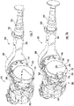
- FIG. 1 is a schematic top-plan view of a vehicle 2 having one or more modular electric axle head assemblies according to an embodiment of the disclosure.
- the vehicle 2 may be a hybrid vehicle having an engine 4 that is used to provide the rotational power necessary to drive a front axle system 6 of the vehicle 2.
- the engine 4 of the vehicle 2 can be an internal combustion engine, an external combustion engine, a heat engine, a gas turbine and/or a steam turbine.
- Drivingly connected to an end of the engine 4 is an engine output shaft 8.
- Drivingly connecting the engine 4 of the vehicle 2 to a transmission 10 is a transmission input shaft 12. As illustrated in FIG. 1 of the disclosure, the transmission input shaft 12 is drivingly connected to an end of the engine output shaft 8 opposite the engine 4.
- the transmission 10 is a power management system which provides controlled application of the rotational power generated by the engine 4 by means of a gear box.
- a transmission output shaft 14 is drivingly connected to an end of the transmission 10 opposite the transmission input shaft 12.
- the transmission output shaft 14 drivingly connects the transmission 10 to a differential 16 of the front axle system 6 via a front axle differential input shaft 18.
- the front axle differential 16 is a set of gears that allows the outer drive wheel(s) of the vehicle 2 to rotate at a faster rate that the inner drive wheel(s). The rotational power is transmitted through the front axle system 6 as described in more detail below.
- the front axle system 6 further includes a first front axle half shaft 20 and a second front axle half shaft 22.
- the first front axle half shaft 20 extends substantially perpendicular to the front axle differential input shaft 18.
- a first end portion 24 of the first front axle half shaft 20 is drivingly connected to a first front axle wheel assembly 26 and a second end portion 28 of the first front axle half shaft 20 is drivingly connected to an end of the front axle differential 16.
- the second end portion 28 of the first front axle half shaft 20 is drivingly connected to a differential side gear, a separate stub shaft, a separate coupling shaft, a first front axle differential output shaft, a first front axle half shaft disconnect system and/or a shaft that is formed as part of a differential side gear.
- the second front axle half shaft 22 also extends substantially perpendicular to the front axle differential input shaft 18.
- a first end portion 30 of the second front axle half shaft 22 is drivingly connected to a second front axle wheel assembly 32 and a second end portion 34 of the second front axle half shaft 22 is drivingly connected to an end of the front axle differential 16 opposite the first front axle input shaft 20.
- the second end portion 34 of the second front axle half shaft 22 is drivingly connected to a differential side gear, a separate stub shaft, a separate coupling shaft, a second front axle differential output shaft, a second front axle half shaft disconnect system and/or a shaft that is formed as part of a differential side gear.
- the vehicle 2 further includes a rear tandem axle system 36 having a forward tandem axle system 38 and a rear tandem axle system 40.
- the rear tandem axle system 36 includes a modular electric axle head assembly 42.
- the modular electric axle head assembly 42 provides the rotational power needed to drive the forward tandem axle system 38 and/or the rear tandem axle system 40 of the vehicle 2.
- the modular electric axle head assembly 42 includes an electric motor 44 that is drivingly connected to an electric motor output shaft 46.
- Drivingly connected to an end of the electric motor output shaft 46 opposite the electric motor 44 is a gear assembly 48.
- the gear assembly 48 is a system of gears (not shown) that reduces the overall rotational speed and increases the torque generated by the electric motor 44 of the modular electric axle head assembly 42.
- inter-axle differential 50 Drivingly connected to an end of the gear assembly 48 of the modular electric axle head assembly 42 opposite the electric motor 44 is an inter-axle differential 50 of a forward tandem axle differential 52 of the forward tandem axle system 38.
- the inter-axle differential 50 is a device that divides the rotational power generated by the electric motor 44 between the forward tandem axle system 38 and the rear tandem axle system 40 of the vehicle 2.
- the inter-axle differential 50 is drivingly connected to the forward tandem axle differential 52 and a forward tandem axle system output shaft 54.
- the forward tandem axle differential 52 is a set of gears that allows the outer drive wheel(s) of a vehicle 2 to rotate at a faster rate than the inner drive wheel(s).
- the forward tandem axle system 38 further includes the use of a first forward tandem axle half shaft 54 and a second forward tandem axle half shaft 58.
- a first end portion 60 of the first forward tandem axle half shaft 54 is drivingly connected to a first forward tandem axle wheel assembly 62 and a second end portion 64 of the first forward tandem axle half shaft 54 is drivingly connected to a side of the forward tandem axle differential 52.
- the second end portion 64 of the first forward tandem axle half shaft 54 is drivingly connected to a forward tandem axle differential side gear, a separate stub shaft, a separate coupling shaft, a first forward tandem axle differential output shaft, a first forward tandem axle half shaft disconnect system and/or a shaft that is formed as part of a forward tandem axle differential side gear.
- a first end portion 66 of the second forward tandem axle half shaft 58 is drivingly connected to a second forward tandem axle wheel assembly 68.
- a second end portion 70 of the second forward tandem axle half shaft 58 is drivingly connected to a side of the forward tandem axle differential 52 opposite the first forward tandem axle half shaft 54.
- the second end portion 70 of the second forward tandem axle half shaft 58 is drivingly connected to a forward tandem axle differential side gear, a separate stub shaft, a separate coupling shaft, a second forward tandem axle differential output shaft, a second forward tandem axle half shaft disconnect system and/or a shaft that is formed as part of a forward tandem axle differential side gear.
- One end of the forward tandem axle system output shaft 54 is drivingly connected to a side of the inter-axle differential 50 opposite the modular electric axle head assembly 42.
- Drivingly connected to an end of the forward tandem axle system output shaft 54 opposite the inter-axle differential 50 is a shaft 72.
- the shaft 72 extends from the forward tandem axle system 38 toward the rear tandem axle system 40 of the vehicle 2.
- the shaft 72 is a drive shaft, a prop shaft, a Cardan shaft, a double cardan shaft, a universal joint shaft or a universal coupling shaft.
- a rear tandem axle system input shaft 74 Drivingly connected to an end of the shaft 72 opposite the forward tandem axle system output shaft 54 is a rear tandem axle system input shaft 74.
- An end of the rear tandem axle system input shaft 74 opposite the shaft 72 is drivingly connected to a rear tandem axle differential 76 of the rear tandem axle system 40 of the vehicle 2.
- the rear tandem axle differential 76 is a set of gears that allows the outer drive wheel(s) of a vehicle 2 to rotate at a faster rate than the inner drive wheel(s).
- the rear tandem axle system input shaft 74 drivingly connects the inter-axle differential 50 to the rear tandem axle differential 76 of the rear tandem axle system 40 of the vehicle 2.
- the rotational power is transmitted through the rear tandem axle system 40 as described in more detail below.
- the rear tandem axle system 40 further includes the use of a first rear tandem axle half shaft 78 and a second rear tandem axle half shaft 80.
- the first rear tandem axle half shaft 78 extends substantially perpendicular to the rear tandem axle system input shaft 74.
- a first end portion 82 of the first rear tandem axle half shaft 78 is drivingly connected to a first rear tandem axle wheel assembly 84 and a second end portion 86 of the first rear tandem axle half shaft 78 is drivingly connected to a side of the rear tandem axle differential 76.
- the second end portion 86 of the first rear tandem axle half shaft 78 is drivingly connected to a rear tandem axle differential side gear, a separate stub shaft, a separate coupling shaft, a first rear tandem axle differential output shaft, a first rear tandem axle half shaft disconnect system and/or a shaft that is formed as part of a rear tandem axle differential side gear.
- a first end portion 88 of the second rear tandem axle half shaft 80 is drivingly connected to a second rear tandem axle wheel assembly 90.
- a second end portion 92 of the second rear tandem axle half shaft 80 is drivingly connected to a side of the rear tandem axle differential 76 opposite the first rear tandem axle half shaft 78.
- the second end portion 92 of the second rear tandem axle half shaft 80 is drivingly connected to a rear tandem axle differential side gear, a separate stub shaft, a separate coupling shaft, a second rear tandem axle differential output shaft, a second rear tandem axle half shaft disconnect system and/or a shaft that is formed as part of a rear tandem axle differential side gear.
- FIG. 2 is a schematic top-plan view of the vehicle 2 illustrated in FIG. 1 according to an alternative embodiment bf the disclosure where the vehicle 2 has one or more modular electric axle head assemblies according to an embodiment of the disclosure.
- the vehicle 2 illustrated in FIG. 2 of the disclosure is the same as the vehicle 2 illustrated in FIG. 1 , except where specifically noted below.
- the vehicle 2 does not include the engine 2 and the forward tandem axle differential 52 having the inter-axle differential 50 illustrated in FIG. 1 .
- the vehicle 2 is an electric drive vehicle.
- the front axle modular electric axle head assembly 100 provides the rotational power necessary to drive the front axle system 6 of the vehicle 2.
- the front axle modular electric axle head assembly 100 includes an electric motor 102 that is drivingly connected to an electric motor output shaft 104. Drivingly connected to an end of the electric motor output shaft 104 opposite the electric motor 102 is a gear assembly 106.
- the gear assembly 106 is a system of gears (not shown) that reduces the overall rotational speed and increases the torque generated by the electric motor 102 of the front axle modular electric axle head assembly 100.
- Drivingly connected to an end of the gear assembly 106 of the front axle modular electric axle head assembly 100 opposite the electric motor 102 is the front axle differential 16 of the front axle system 6.
- a forward tandem axle modular electric axle head assembly 108 provides the rotational power necessary to drive the forward tandem axle system 38 of the vehicle 2.
- the forward tandem axle modular electric axle head assembly 108 includes an electric motor 110 that is drivingly connected to an electric motor output shaft 112. Drivingly connected to an end of the electric motor output shaft 112 opposite the electric motor 110 is a gear assembly 114.
- the gear assembly 114 is a system of gears (not shown) that reduces the overall rotational speed and increases the torque generated by the electric motor 110 of the forward tandem axle modular electric axle head assembly 108.
- the forward tandem axle differential 116 is a set of gears that allows the outer drive wheel(s) of a vehicle 2 to rotate at a faster rate than the inner drive'wheel(s).
- the second end portion 64 of the first forward tandem axle half shaft 56 is drivingly connected to a side of the forward tandem axle differential 116.
- the second end portion 64 of the first forward tandem axle half shaft 56 is drivingly connected to a forward tandem axle differential side gear, a separate stub shaft, a separate coupling shaft, a first forward tandem axle differential output shaft, a first forward tandem axle half shaft disconnect system and/or a shaft that is formed as part of a forward tandem axle differential side gear.
- the second end portion 70 of the second forward tandem axle half shaft 58 is drivingly connected to a side of the forward tandem axle differential 116 opposite the first forward tandem axle half shaft 56.
- the second end portion 70 of the second forward tandem axle half shaft 58 is drivingly connected to a forward tandem axle differential side gear, a separate stub shaft, a separate coupling shaft, a second forward tandem axle differential output shaft, a second forward tandem axle half shaft disconnect system and/or a shaft that is formed as part of a forward tandem axle differential side gear.
- a rear tandem axle modular electric axle head assembly 118 provides the rotational power necessary to drive the rear tandem axle system 40 of the vehicle 2.
- the rear tandem axle modular electric axle head assembly 118 includes an electric motor 120 that is drivingly connected to an electric motor output shaft 122.
- Drivingly connected to an end of the electric motor output shaft 122 opposite the electric motor 120 is a gear assembly 124.
- the gear assembly 124 is a system of gears (not shown) that reduces the overall rotational speed and increases the torque generated by the electric motor 120 of the rear tandem axle modular electric axle head assembly 118.
- Drivingly connected to an end of the gear assembly 124 opposite the electric motor 120 is the rear tandem axle differential 76 of the rear tandem axle system 40 of the vehicle 2.
- FIG. 3 is a schematic top-plan view of the vehicle 2 illustrated in FIGS. 1 and 2 according to still another embodiment of the disclosure where the vehicle 2 has one or more modular electric axle head assemblies according to an embodiment of the disclosure.
- the vehicle 2 illustrated in FIG. 3 of the disclosure is the same as the vehicle 2 illustrated in FIGS. 1 and 2 , except where specifically noted below.
- the vehicle 2 does not include the front axle modular electric axle head assembly 100 illustrated in FIG. 2 .
- the vehicle 2 is a hybrid vehicle.
- the shaft 150 extends from the transmission 10 to the forward tandem axle system 38 of the vehicle 2.
- the shaft 72 is a drive shaft, a prop shaft, a Cardan shaft, a double cardan shaft, a universal joint shaft or a universal coupling shaft.
- An end of the forward tandem axle system input shaft 152 opposite the shaft 150 is drivingly connected to the forward tandem axle differential 116 of the forward tandem axle system 38 of the vehicle 2.
- the rear tandem axle system 40 of the vehicle 2 includes the rear tandem axle modular electric axle head assembly 118.
- the rear tandem axle modular electric axle head assembly 118 provides the rotational power necessary to drive rear tandem axle system 40 of the vehicle 2.
- the rear tandem axle modular electric axle head assembly 118 may be activated to selectively transition the vehicle 2 from a 6x2 driving mode to a 6x4 driving mode on the fly without having to stop the vehicle 2.
- FIG. 4 is a schematic top-plan view of another vehicle 200 having one or more modular electric axle head assemblies according to an embodiment of the disclosure.
- the vehicle 200 may be a hybrid vehicle having an engine 202 that is used to provide the rotational power necessary to drive a front axle system 204 of the vehicle 200.
- the engine 202 of the vehicle 200 can be an internal combustion engine, an external combustion engine, a heat engine, a gas turbine and/or a steam turbine.
- Drivingly connected to an end of the engine 202 is an engine output shaft 206.
- Drivingly connecting the engine 202 of the vehicle 200 to a transmission 208 is a transmission input shaft 210.
- the transmission input shaft 210 is drivingly connected to an end of the engine output shaft 206 opposite the engine 202.
- the transmission 208 is a power management system which provides controlled application of the rotational power generated by the engine 202 by means of a gear box.
- a transmission output shaft 212 is drivingly connected to an end of the transmission 208 opposite the transmission input shaft 210.
- the transmission output shaft 212 drivingly connects the transmission 208 to a differential 214 of the front axle system 204 via a front axle differential input shaft 216.
- the front axle differential 214 is a set of gears that allows the outer drive wheel(s) of the vehicle 200 to rotate at a faster rate that the inner drive wheel(s). The rotational power is transmitted through the front axle system 204 as described in more detail below.
- the front axle system 204 further includes a first front axle half shaft 216 and a second front axle half shaft 218.
- the first front axle half shaft 216 extends substantially perpendicular to the front axle differential input shaft 216.
- a first end portion 220 of the first front axle half shaft 216 is drivingly connected to a first front axle wheel assembly 222 and a second end portion 224 of the first front axle half shaft 216 is drivingly connected to an end of the front axle differential 214.
- the second end portion 224 of the first front axle half shaft 216 is drivingly connected to a differential side gear, a separate stub shaft, a separate coupling shaft, a first front axle differential output shaft, a first front axle half shaft disconnect system and/or a shaft that is formed as part of a differential side gear.
- Extending substantially perpendicular to the front axle differential input shaft 216 is the second front axle half shaft 218 of the front axle system 204 of the vehicle 200.
- a first end portion 226 of the second front axle half shaft 218 is drivingly connected to a second front axle wheel assembly 228 and a second end portion 230 of the second front axle half shaft 218 is drivingly connected to an end of the front axle differential 214 opposite the first front axle input shaft 216.
- the second end portion 230 of the second front axle half shaft 218 is drivingly connected to a differential side gear, a separate stub shaft, a separate coupling shaft, a second front axle differential output shaft, a second front axle half shaft disconnect system and/or a shaft that is formed as part of a differential side gear.
- a rear axle modular electric axle head assembly 232 provides the rotational power necessary to drive a rear axle system 234 of the vehicle 200.
- the rear axle modular electric axle head assembly 232 includes an electric motor 236 that is drivingly connected to an electric motor output shaft 238.
- Drivingly connected to an end of the electric motor output shaft 238 opposite the electric motor 236 is a gear assembly 240.
- the gear assembly 240 is a system of gears (not shown) that reduces the overall rotational speed and increases the torque generated by the electric motor 236 of the rear axle modular electric axle head assembly 232.
- the rear axle differential 242 is a set of gears that allows the outer drive wheel(s) of a vehicle 200 to rotate at a faster rate than the inner drive wheel(s). The rotational power is transmitted through the rear axle system 234 as described in more detail below.
- the rear axle system 234 further includes the use of a first rear axle half shaft 244 and a second rear axle half shaft 246.
- a first end portion 248 of the first rear axle half shaft 244 is drivingly connected to a first rear axle wheel assembly 250 and a second end portion 252 of the first rear axle half shaft 244 is drivingly connected to a side of the rear axle differential 242.
- the second end portion 252 of the first rear axle half shaft 244 is drivingly connected to a rear axle differential side gear, a separate stub shaft, a separate coupling shaft, a first rear axle differential output shaft, a first rear axle half shaft disconnect system and/or a shaft that is formed as part of a rear axle differential side gear.
- a first end portion 254 of the second rear axle half shaft 246 is drivingly connected to a second rear axle wheel assembly 256.
- a second end portion 258 of the second rear axle half shaft 246 is drivingly connected to a side of the rear axle differential 242 opposite the first rear axle half shaft 246.
- the second end portion 258 of the second rear axle half shaft 246 is drivingly connected to a rear axle differential side gear, a separate stub shaft, a separate coupling shaft, a second rear axle differential output shaft, a second rear axle half shaft disconnect system and/or a shaft that is formed as part of a rear axle differential side gear.
- FIG. 5 is a schematic top-plan view of the vehicle 200 illustrated in FIG. 4 having one or more modular electric axle head assemblies according to an embodiment of the disclosure.
- the vehicle 200 illustrated in FIG. 5 of the disclosure is the same as the vehicle 200 illustrated in FIG. 4 , except where specifically noted below.
- the vehicle 200 does not include the engine 202 illustrated in FIG. 4 .
- the vehicle 200 is an electric drive vehicle.
- the front axle modular electric axle head assembly 260 provides the rotational power necessary to drive the front axle system 204 of the vehicle 200.
- the front axle modular electric axle head assembly 260 includes an electric motor 262 that is drivingly connected to an electric motor output shaft 264. Drivingly connected to an end of the electric motor output shaft 264 opposite the electric motor
- the gear assembly 266 is a system of gears (not shown) that reduces the overall rotational speed and increases the torque generated by the electric motor 262 of the front axle modular electric axle head assembly 260.
- Drivingly connected to an end of the gear assembly 266 of the front axle modular electric axle head assembly 260 opposite the electric motor 262 is the front axle differential 214 of the front axle system 204.
- FIGS. 6-6F provide a schematic illustration of an axle assembly 300 having a modular electric axle head assembly 302 according to an embodiment of the disclosure useful for understanding the invention.
- the axle assembly 300 has a first axle half shaft housing 304, a second axle half shaft housing 306 and a banjo portion 308 interposed between the first and second axle half shaft housings 304 and 306.
- the axle assembly 300 may be a front axle assembly, a rear axle assembly, a forward tandem axle assembly and/or a rear tandem axle assembly.
- the axle assembly 300 may be a conventional axle assembly having the modular electric axle head assembly 302.
- the first axle half shaft housing 304 has an inner surface 310, an outer surface 312, a first end portion 314 and a second end portion 316. As best seen in FIG. 6B of the disclosure, the inner surface 310 and the outer surface 312 of the first axle half shaft housing 304 defines a hollow portion 318 therein.
- the hollow portion 318 of the first axle half shaft housing 304 of the axle assembly 300 may have a size and shape to receive at least a portion of a first axle half shaft 319.
- first flange 320 Integrally connected to at least a portion of the outer surface 310 of the first end portion 314 of the first axle half shaft housing 304 is a first flange 320.
- the first flange 320 may be integrally connected to the first end portion 314 of the first axle half shaft housing 304 by using one or more adhesives, one or more welds, a threaded connection and/or one or more mechanical fasteners.
- the first flange 320 may be integrally formed as part of the first end portion 314 of the first axle half shaft housing 304.
- first spindle 322 Disposed outward from the first flange 320 is a first spindle 322.
- the first spindle 322 provides rotational support for a first wheel end assembly (not shown).
- the first spindle 322 may be integrally connected to at least a portion of the first end portion 314 of the first axle half shaft housing 304.
- the first spindle 322 may be integrally connected to the first end portion 314 of the first axle half shaft housing 304 by using one or more adhesives, one or more welds, a threaded connection and/or one or more mechanical fasteners.
- the first spindle 322 may be integrally formed as part of the first end portion 314 of the first axle half shaft housing 304.
- Integrally connected to at least a portion of the second end portion 316 of the first axle half shaft housing 304 is an end of the banjo portion 308 of the axle assembly 300. It is within the scope of this disclosure and as a non-limiting example, that the second end portion 316 of the first axle housing 304 may form at least a portion of the banjo portion 308 of the axle assembly 300. In accordance with an alternative embodiment of the disclosure and as a non-limiting example, the second end portion 316 of the first axle half shaft housing 304 may be connected to the end of the banjo portion 308 of the axle assembly 300 by using one or more adhesives, one or more welds, a threaded connection and/or one or more mechanical fasteners.
- the second axle half shaft housing 306 has an inner surface 324, an outer surface 326, a first end portion 328 and a second end portion 330.
- the inner surface 324 and the outer surface 326 of the second axle half shaft housing 306 defines a hollow portion 332 therein.
- the hollow portion 332 of the second axle half shaft housing 306 of the axle assembly 300 may have a size and shape to receive at least a portion of a second axle half shaft 333.
- Integrally connected to at least a portion of the first end portion 328 of the second axle half shaft housing 306 is an end of the banjo portion 308 of the axle assembly 300 opposite the first axle half shaft housing 304. It is within the scope of this disclosure and as a non-limiting example, that the first end portion 328 of the second axle housing 306 may form at least a portion of the banjo portion 308 of the axle assembly 300.
- first end portion 328 of the second axle half shaft housing 306 may be connected to the end of the banjo portion 308 of the axle assembly 300 opposite the first axle half shaft housing 304 by using one or more adhesives, one or more welds, a threaded connection and/or one or more mechanical fasteners.
- At least a portion of a second flange 334 may be integrally connected to at least a portion of the outer surface 324 of the second end portion 330 of the second axle half shaft housing 306 of the axle assembly 300.
- the second flange 334 may be integrally connected to the second end portion 330 of the second axle half shaft housing 306 by using one or more adhesives, one or more welds, a threaded connection and/or one or more mechanical fasteners.
- the second flange 330 may be integrally formed as part of the second end portion 330 of the second axle half shaft housing 306.
- the second spindle 336 provides rotational support for a second wheel end assembly (not shown).
- the second spindle 336 may be integrally connected to at least a portion of the second end portion 330 of the second axle half shaft housing 306.
- the second spindle 336 may be integrally connected to the second end portion 330 of the second axle half shaft housing 306 by using one or more adhesives, one or more welds, a threaded connection and/or one or more mechanical fasteners.
- the second spindle 226 may be integrally formed as part of the second end portion 330 of the second axle half shaft housing 306 of the axle assembly 300.
- the banjo portion 308 of the axle assembly 300 has an outer surface 338, an inner surface 340, an inboard side 342 and an outboard side 344.
- the outer surface 338 and the inner surface 340 of the banjo portion 308 of the axle assembly 300 defines a hollow portion 346 therein.
- the hollow portion 346 of the banjo portion 308 of the axle assembly 300 may have a size and shape to receive and retain at least a portion of the modular electric axle head assembly 302.
- first opening 348 Extending from the outer surface 338 to the inner surface 340 of the inboard side 342 of the banjo portion 308 of the axle assembly 308 is a first opening 348.
- the first opening 348 in the inboard side 342 of the banjo portion 308 of the axle assembly 300 may have a size and a shape to receive at least a portion of the modular electric axle head assembly 302.
- a second opening 350 extending from the outer surface 338 to the inner surface 340 of the outboard side 344 of the banjo portion 308 of the axle assembly 300 is a second opening 350.
- the second opening 350 in the outboard side 344 of the banjo portion 308 of the axle assembly 300 may have a size and a shape to receive at least a portion of the modular electric axle head assembly 302.
- a cover 352 Integrally connected to at least a portion of the outer surface 338 of the outboard side 344 of the banjo portion 308 of the axle assembly 300 is a cover 352. At least a portion of the cover 354 sealingly engages at least a portion of the outer surface 338 of the outboard side 344 of the banjo portion 308 of the axle assembly 300. The sealing engagement between the cover 352 and the outer surface 338 of the outboard side 344 of the banjo portion 308 prevents the migration of dirt, debris and/or moisture into the hollow portion 346 of the banjo portion 308 of the axle assembly 300.
- the axle assembly 300 may further include the use of a gasket (not shown) to aid in facilitating the sealing engagement between the outer surface 338 of the outboard side 344 of the banjo portion 308 and the cover 352 of the axle assembly 300.
- the gasket (not shown) will fill any gaps between the outer surface 338 of the outboard side 344 of the banjo portion 308 and the cover 352 when assembled.
- the cover 352 may be integrally connected to at least a portion of the outboard side 344 of the banjo portion 308 of the axle assembly 300 by using one or more adhesives, one or more welds, a threaded connection and/or one or more mechanical fasteners.
- the cover 352 may have a size and shape to receive at least a portion of the modular electric axle head assembly 302. According to the embodiment of the disclosure illustrated in FIGS. 6 and 6B of the disclosure and as a non-limiting example, the cover 352 may be substantially disk-shaped member having a protruding portion 354.
- the modular electric axle head assembly 302 includes a motor 356 that is drivingly connected to an end of a motor output shaft 358.
- the motor 356 may be in electrical communication with a source of electrical power (not shown) to provide the rotational power necessary to drive the wheels (not shown) of the axle assembly 300.
- the motor 356 may be an electric motor or any other device that is able to convert an amount of electrical energy into an amount of mechanical energy.
- the motor 356 may be capable of acting as a generator when not providing the rotations power needed to drive the modular electric axle had assembly 302.
- the power generated by the motor 356 when acting as a generator may be stored for later use.
- a gear assembly housing 360 Integrally connected to at least a portion of the outer surface 338 of the inboard side 342 of the banjo portion 308 of the axle assembly 300 is a gear assembly housing 360 having an inner surface 362, an outer surface 364, a first end portion 366, a second end potion 368, an inboard portion 370, an outboard portion 372 and an intermediate portion 374 interposed between the inboard and outboard portions 370 and 372 of the gear assembly housing 360.
- the inner surface 362 and the outer surface 364 of the gear assembly housing 360 defines a hollow portion 376 therein.
- the hollow portion 376 of the gear assembly housing 360 may have a size and a shape to receive and retain at least a portion of a gear assembly 378.
- the hollow portion 376 of the gear assembly housing 360 may have a substantially triangular cross-sectional shape.
- a flange portion 380 extends outward from at least a portion of the outer surface 364 of the second end portion 368 of the inboard portion 370 of the gear assembly housing 360.
- the flange portion 380 second end portion 368 of the gear assembly housing 360 has one or more apertures 384 extending from a first end 386 to a second end 388 of the flange portion 308 of the gear assembly housing 360.
- the one or more apertures 384 of the flange portion 380 of the second end portion 368 of the gear assembly housing 360 are of a size and shape to receive and/or retain one or more mechanical fasteners 390.
- the one or more apertures 382 may have a plurality of axially extending threads (not shown) that are complementary to a plurality of axially extending threads (not shown) on the one or more mechanical fasteners 390.
- the flange portion 380 of the second end portion 368 of the gear assembly housing 360 may be substantially triangular in shape.
- the motor mounting member 392 has a first side 394, a second side 396, an inboard portion 398 and an outboard portion 400.
- the motor mounting member 392 may be a modular member having a size and shape to needed to mount the motor 356 to at least a portion of the second end portion 368 of the gear assembly housing 360 of the modular electric axle head assembly 302. It is within the scope of this disclosure, that the shape of the motor mounting member 392 may change depending on the type of motor used and the shape of the motor used in the modular electric axle head assembly 302. As a non-limiting example and as best seen in FIGS.
- the motor mounting member 392 may be substantially triangular in shape having a first substantially straight side 402, a second substantially straight side 404 and a third substantially straight side 406. Additionally, as a non-limiting example and as best seen in FIGS. 6C and 6D of the disclosure and as a non-limiting example, the third substantially straight side 406 of the motor mounting member 392 has an arcuate portion 408 having a radius R1 and extending into the motor mounting member 392.
- a motor mounting portion 410 extends outward from at least a portion of the second side 396 of the motor mounting member 392. It is within the scope of this disclosure and as a non-limiting example that the motor mounting portion 410 may have a substantially cylindrical shape that is complementary to a mounting portion 412 of the motor 356.
- a motor mounting member opening 415 Extending from a first side 394 to a second side 396 of the motor mounting portion 410 of the motor mounting member 392 is a motor mounting member opening 415. It is within the scope of this disclosure and as a non-limiting example that the motor mounting member opening 415 may have a size and a shape to receive at least a portion of the motor output shaft 358 of the motor 356.
- the one or more motor attachment apertures 414 of the motor mounting portion 410 of the motor mounting member 392 are disposed circumferentially along the outer periphery of the motor mounting member 392.
- the one or more motor attachment apertures 414 are of a size and a shape to receive and/or retain one or more mechanical fasteners 416.
- the one or more motor attachment apertures 414 of motor mounting portion 410 may have a plurality of axially extending threads (not shown) that are complementary to a plurality of axially extending threads (not shown) on the one or more mechanical fasteners 416.
- the one or more attachment apertures 418 in the motor 356 are complementary to the one or more motor attachment apertures 414 in the motor mounting portion 410 of the motor mounting member 392.
- the one or more attachment apertures 418 of the motor 356 have a plurality of axially extending threads (not shown) that are complementary to the plurality of axially extending threads (not shown) on the one or more mechanical fasteners 416.
- the one or more gear housing attachment apertures 420 are disposed along the outer periphery of the first, second and/or third substantially straight sides 402, 404 and/or 406 of the motor mounting member 392.
- the one or more gear housing attachment apertures 420 are of a size and shape to receive and retain the one or more mechanical fasteners 390.
- the gear housing attachment apertures 420 of the motor mounting member 392 have a plurality of axially extending threads (not shown) that are complementary to the plurality of axially extending threads (not shown) on the one or more mechanical fasteners 390.
- the first side 394 of the motor mounting member 392 may be in direct contact with at least a portion of a second end 421 of the gear assembly housing 360 of the modular electric axle head assembly 302.
- a flange portion 422 extends outward from at least a portion of the outer surface 364 of the first end portion 366 of the gear assembly housing 360.
- the flange portion 422 first end portion 366 of the gear assembly housing 360 has one or more apertures 424 extending from a first end 426 to a second end 428 of the flange portion 422 of the gear assembly housing 360.
- the one or more apertures 424 of the flange portion 422 of the first end portion 366 of the gear assembly housing 360 are of a size and shape to receive and retain one or more mechanical fasteners 430.
- the one or more apertures 424 may have a plurality of axially extending threads (not shown) that are complementary to a plurality of axially extending threads (not shown) on the one or more mechanical fasteners 430.
- the flange portion 422 of the first end portion 366 of the gear assembly housing 360 may be substantially triangular in shape.
- the opening 434 in the first end 432 of the gear assembly housing 360 has a size and shape necessary to facilitate the assembly of the gear assembly 378 within the hollow portion 376 of the gear assembly housing 360.
- a gear housing cover 436 Disposed outward from at least a portion of the first end 432 of the gear assembly housing 360 is a gear housing cover 436 having a first side 438 and a second side 440.
- the gear housing cover 436 may have a size and shape needed to seal the opening 434 of the first end 432 of the gear assembly housing 360 from the migration of first, debris and/or moisture into the hollow portion 376 of the gear assembly housing 360. Additionally, the gear housing cover 436 may be selectively removable providing access to the gear assembly 378 to make repairs, replacements and/or modifications to one or more of the components of the modular electric axle head assembly 302.
- the gear housing cover 436 may have a shape that is complementary to the flange portion 422 of the first end portion 366 of the gear assembly housing 360. It is therefore within the scope of this disclosure and as a non-limiting example, that the gear housing cover 436 may have a substantially triangular shape.
- Extending from the first side 438 to the second side 440 of the gear housing cover 436 is one or more apertures 442 that are complementary to the one or more apertures 424 in the flange portion 422 of the first end portion 366 of the gear assembly housing 360.
- the one or more apertures 442 of the gear housing cover 436 are disposed along the outer periphery of the gear housing cover 436.
- the one or more apertures 442 of the gear housing cover 436 are of a size and shape to receive and/or retain the one or more mechanical fasteners 430.
- the one or more apertures 442 of the gear housing cover 436 may include a plurality of axially extending threads (not shown) that are complementary to the plurality of axially extending threads (not shown) on the one or more mechanical fasteners 430.
- the second side 440 of the gear housing cover 436 may be in direct contact with at least a portion of the first end 432 of the gear assembly housing 360 of the modular electric axle head assembly 302.
- a motor output shaft opening 444 extends from the outer surface 364 to the inner surface 362 of the second end 421 of the gear assembly housing 360.
- the motor output shaft opening 444 may have a size and a shape needed to receive and/or retain at least a portion of the motor output shaft 358 of the motor 356.
- first gear shaft 446 Extending co-axially and drivingly connected with the motor output shaft 358 of the motor 356 is a first gear shaft 446 having a first end portion 448, a second end portion 450 and an outer surface 452.
- first bearing assemblies 454 disposed within a first receiving portion 456 in an outboard portion 458 of the second side 440 of the gear housing cover 436.
- the one or more first bearing assemblies 454 may be one or more tapered roller bearings, one or more rolling element bearings, one or more needle bearings, one or more magnetic bearings and/or one or more bushings.
- first gear 460 Connected to at least a portion of the outer surface 452 of the first end portion 448 of the first gear shaft 446 is a first gear 460.
- Circumferentially extending from at least a portion of an outer surface 462 of the first gear 460 is a plurality of first gear teeth 464.
- the first gear 460 may be integrally formed as part of the first end portion 448 of the first gear shaft 446.
- the first gear 460 may be integrally connected to at least a portion of the first end portion 448 of the first gear shaft 446 by using one or more adhesives, one or more mechanical fasteners, one or more welds, a threaded connection and/or a splined connection. It is within the scope of this disclosure and as a non-limiting example that the first gear 460 may be a first reduction gear for the gear assembly 378 of the modular electric axle head assembly 302.
- the plurality of first gear teeth 464 extending from the outer surface 462 of the first gear 460 may be a plurality of hypoid gear teeth, spiral bevel gear teeth, helical gear teeth, spur gear teeth, double hypoid gear teeth, double spiral bevel gear teeth or double helical gear teeth.
- the second end portion 450 of the first gear shaft 446 has a hollow interior portion 466 extending inward from a second end 468 of the first gear shaft 446.
- the hollow interior portion 466 of the second end portion 450 of the first gear shaft 446 may have a size and shape needed to receive and/or retain at least a portion of the motor output shaft 358.
- the second end portion of the first gear shaft may be connected to at least a portion of the motor output shaft of the motor by using one or more adhesives, one or more mechanical fasteners, one or more welds, a threaded connection and/or a splined connection.
- Circumferentially extending along at least a portion of an inner surface 470 defining the hollow interior portion 466 of the second end portion 450 of the first gear shaft 446 is a plurality of axially extending splines 472.
- the plurality of axially extending splines 472 are complementary to and meshingly engaged with a plurality of axially extending splines 474 on an outer surface 476 of the motor output shaft 358.
- the meshing engagement of the plurality of axially extending splines 472 and 474 of the first gear shaft 446 and the motor output shaft 358 rotationally fixes the first gear shaft 446 to the motor output shaft 358.
- the second end portion 450 of the first gear shaft 466 may be received within one or more second bearing assemblies 478 in the motor output shaft opening 444 of the second end 421 of the gear assembly housing 360.
- the one or more second bearing assemblies 478 may be one or more tapered roller bearings, one or more rolling element bearings, one or more needle bearings, one or more magnetic bearings and/or one or more bushings.
- a second gear shaft 480 Extending parallel with the first gear shaft 446 and the motor output shaft 358 of the modular electric axle head assembly 302 is a second gear shaft 480 having a first end portion 482, a second end portion 484 and an outer surface 486. As best seen in FIGS. 6A and 6B of the disclosure, at least a portion of the first end portion 482 of the second gear shaft 480 may be received within one or more third bearing assemblies 488 disposed within a second receiving portion 490 in an outboard portion 492 of the second side 440 of the gear housing cover 436. Additionally, as best seen in FIGS.
- the second end portion 484 of the second gear shaft 480 may be received within one or more fourth bearing assemblies 494 disposed within a receiving portion 496 in the inner surface 362 of the outboard portion 372 of the second end portion 368 of the gear assembly housing 360.
- the one or more bearing assemblies 488 and 494 of the modular electric axle head assembly 302 may be one or more tapered roller bearings, one or more rolling element bearings, one or more needle bearings, one or more magnetic bearings, one or more cylindrical roller bearings and/or one or more bushings.
- the first and second axle half shafts 319 and 333 have a centerline C1
- the first gear shaft 446 has a centerline C2
- the second gear shaft 480 has a centerline C3. It is within the scope of this disclosure and as a non-limiting example that a linear distance LD1 between the centerline C2 of the first gear shaft 446 and the centerline C3 of the second gear shaft 480 may be less than a linear distance LD2 between the centerline C3 of the second gear shaft 480 and the centerline C1 of the first and second axle half shafts 319 and 333.
- a second gear 498 Connected to at least a portion of the outer surface 486 of the first end portion 482 of the second gear shaft 480 is a second gear 498.
- Circumferentially extending from at least a portion of an outer surface 500 of the second gear 498 is a plurality of second gear teeth 502 that are complementary to and meshingly engaged with the plurality of first gear teeth 464 on the first gear 460.
- the second gear 498 may be integrally formed as part of the first end portion 482 of the second gear shaft 480.
- the second gear 498 may be integrally connected to at least a portion of the first end portion 482 of the second gear shaft 480 by using one or more adhesives, one or more mechanical fasteners, one or more welds, a threaded connection and/or a splined connection. It is within the scope of this disclosure and as a non-limiting example that the second gear 498 may be an intermediate gear for the gear assembly 378.
- the plurality of second gear teeth 502 extending from the outer surface 500 of the second gear 498 may be a plurality of hypoid gear teeth, spiral bevel gear teeth, helical gear teeth, spur gear teeth, double hypoid gear teeth, double spiral bevel gear teeth or double helical gear teeth.
- a third gear 504. Circumferentially extending from at least a portion of an outer surface 506 of the third gear 504 is a plurality of third gear teeth 508.
- the third gear 504 may be integrally formed as part of the second end portion 484 of the second gear shaft 480.
- the third gear 504 may be integrally connected to at least a portion of the second end portion 484 of the second gear shaft 480 by using one or more adhesives, one or more mechanical fasteners, one or more welds, a threaded connection and/or a splined connection. It is within the scope of this disclosure and as a non-limiting example that the third gear 504 of the gear assembly 378 may be a second reduction gear.
- the plurality of third gear teeth 508 extending from the outer surface 506 of the third gear 504 may be a plurality of hypoid gear teeth, spiral bevel gear teeth, helical gear teeth, spur gear teeth, double hypoid gear teeth, double spiral bevel gear teeth or double helical gear teeth.
- a differential ring gear 510 of a differential assembly 512 Meshingly engaged with at least a portion of the third gear 504 is a differential ring gear 510 of a differential assembly 512.
- the differential ring gear 510 has a first side 514, a second side 516 and an outer surface 518.
- Circumferentially extending along at least a portion of the outer surface 518 of the differential ring gear 510 is a plurality of ring gear teeth 520 that are complementary to and meshingly engaged with the plurality of third gear teeth 508 on the outer surface 506 of the third gear 504.
- the plurality of gear ring teeth 520 extending from the outer surface 518 of the differential ring gear 510 may be a plurality of hypoid gear teeth, spiral bevel gear teeth, helical gear teeth, spur gear teeth, double hypoid gear teeth, double spiral bevel gear teeth or double helical gear teeth.
- axle assembly mounting flange 530 Circumferentially extending from at least a portion of the outer surface 364 of the outboard portion 372 of the gear assembly housing 360 is an axle assembly mounting flange 530 having an inboard portion 532 and an outboard portion 534.
- the axle assembly mounting flange 530 may have a size and shape needed to sealingly engage with the first opening 348 in the inboard side 342 of the banjo portion 308 of the axle assembly 300.
- the sealing engagement between the axle assembly mounting flange 530 and the outer surface 338 of the inboard side 342 of the banjo portion 308 prevents the migration of dirt, debris and/or moisture into the hollow portion 346 of the banjo portion 308 of the axle assembly 300.
- the axle assembly 300 may further include the use of a gasket or supporting ring 536 to aid in facilitating the sealing engagement between the outer surface 338 of the banjo portion 308 and the outboard portion 534 of the axle assembly mounting flange 530.
- the gasket or supporting ring 536 will fill any gaps between the outer surface 338 of the inboard side 342 of the banjo portion 308 and outboard portion 534 of the axle assembly mounting flange 530 when assembled.
- the axle assembly mounting flange 530 may be integrally connected to at least a portion of the inboard side 342 of the banjo portion 308 by using one or more mechanical fasteners 538.
- at least a portion of the outboard portion 534 of the axle assembly mounting flange 530 may be integrally connected to at least a portion of the inboard side 342 of the banjo portion 308 by using one or more adhesives, one or more welds and/or a threaded connection. It is within the scope of this disclosure that the one or more adhesives, one or more welds and/or a threaded connection may be used in combination with or instead of the one or more mechanical fasteners 538.
- first and second protruding portions 540 and 542 of the axle assembly mounting flange 530 of the gear assembly housing 360 are disposed on axially opposing sides of the axle assembly mounting flange 530.
- the first and second protruding portions 540 and 542 of the axle assembly mounting flange 530 of the gear assembly housing 360 provide rotational support or at least a portion of the differential assembly 512.
- Extending from the first side 514 to the second side 516 of the differential ring gear 510 is one or more apertures 544.
- the one or more apertures 544 in the differential ring gear 510 are of a size and shape to receive and/or retain at least a portion of one or more mechanical fasteners 546. It is therefore within the scope of this disclosure and as a non-limiting disclosure that the one or more apertures 544 may have a plurality of axially extending threads (not shown) that are complementary to a plurality of axially extending threads (not shown) on the one or more mechanical fasteners 546.
- Extending outward from at least a portion of the first side 514 of the differential ring gear 510 is an axially protruding portion 548.
- at least a portion of the axially protruding portion 548 may be received within one or more fifth bearing assemblies 552 disposed within an arcuate portion 554 of the first protruding portion 540 of the axle assembly mounting flange 530 of the gear assembly housing 360.
- at least a portion of the arcuate portion 554 of the first protruding portion 540 of the axle assembly mounting flange 530 provides rotational support for the axially protruding portion 548 of the differential ring gear 510.
- the one or more fifth bearing assemblies 552 may be one or more tapered roller bearings, one or more rolling element bearings, one or more needle bearings, one or more magnetic bearings and/or one or more bushings.
- the axially protruding portion 548 of the differential ring gear 510 has a hollow interior portion 550 having a size and shape to receive at least a portion of an end of the first axle half shaft 319.
- the axially protruding portion 548 and the hollow interior portion 550 of the differential ring gear 510 are substantially cylindrical in shape.
- the differential case 556 Disposed outward from at least a portion of the second side 516 of the differential ring gear 510 is a differential case 556.
- the differential case 556 has an inner surface 558, an outer surface 560, a first end portion 562, a second end portion 564 and an intermediate portion 566 disposed between the first and second end portions 562 and 564 of the differential case 556.
- the inner surface 558 and the outer surface 560 of the differential case 556 defines a hollow interior portion 568 therein. As illustrated in FIGS.
- At least a portion of the first end portion 562 of the differential case 556 may be integrally connected to at least a portion of the second side 516 of the differential ring gear 510.
- the first end portion 562 of the differential case 556 may be integrally connected to the second side 516 of the differential ring gear 510 by receiving and retaining at least a portion of the one or more mechanical fasteners 546 within one or more mechanical fastener receiving portions 570.
- the one or more mechanical fastener receiving portions 570 may have a plurality of axially extending threads (not shown) that are complementary to a plurality of axially extending threads (not shown) on the one or more mechanical fasteners 546.
- the second end portion 564 of the differential case 556 has a reduced diameter portion 572.
- at least a portion of the reduced diameter portion 572 of the differential case 556 may be received within one or more sixth bearing assemblies 574 disposed within an arcuate portion 576 of the second protruding portion 542 of the of the axle assembly mounting flange 530.
- the one or more sixth bearing assemblies 574 may be one or more tapered roller bearings, one or more rolling element bearings, one or more needle bearings, one or more magnetic bearings and/or one or more bushings.
- the reduced diameter portion 572 of the differential case 556 has a hollow interior portion 576 having a size and shape to receive at least a portion of an end of the second axle half shaft 333. As best seen in FIGS. 6A and 6B of the disclosure and as a non-limiting example, the reduced diameter portion 572 and the hollow interior portion 576 of the differential case 556 are substantially cylindrical in shape.
- the differential assembly 512 further includes one or more spider gears 578 rotatively connected to a cross pin 580. As illustrated in FIGS. 6A and 6B of the disclosure, at least a portion of each end of the cross pin 580 may be integrally connected to the differential case 556 of the differential assembly 512. Circumferentially extending from at least a portion of an outer surface 582 of the one or more spider gears 578 is a plurality of spider gear teeth 584.
- the plurality of spider gear teeth 584 extending from the outer surface 582 of the one or more spider gears 578 may be a plurality of hypoid gear teeth, spiral bevel gear teeth, helical gear teeth, spur gear teeth, double hypoid gear teeth, double spiral bevel gear teeth or double helical gear teeth.
- Drivingly connected to at least a portion of the one or more spider gears 578 is a first side gear 586 of the differential assembly 512.
- Circumferentially extending from at least a portion of an outer surface 588 of the first side gear 586 is a plurality of first side gear teeth 590 that are complementary to and meshingly engaged with the plurality of spider gear teeth 584 on the outer surface 582 of the one or more spider gears 578.
- circumferentially extending from at least a portion of an inner surface 592 of the first side gear 586 is a plurality of axially extending splines 594.
- the plurality of axially extending splines 594 of the first side gear 586 are complementary to and meshingly engaged with a plurality of axially extending splines 596 on an outer surface 598 of the end first axle half shaft 319 of the axle assembly 300.
- the meshing engagement of the plurality of axially extending splines 594 and 596 on the first side gear 586 and the first axle half shaft 319 drivingly connects the first side gear 586 to the first axle half shaft 319.
- Second side gear 600 of the differential assembly 512 Drivingly connected to at least a portion of the one or more spider gears 578 is a second side gear 600 of the differential assembly 512.
- the first and second side gears 586 and 600 are disposed on axially opposing sides of the one or more spider gears 578 of the differential assembly 512.
- Circumferentially extending from at least a portion of an outer surface 602 of the second side gear 600 is a plurality of second side gear teeth 604 that are complementary to and meshingly engaged with the plurality of spider gear teeth 584 on the outer surface 582 of the one or more spider gears 578.
- circumferentially extending from at least a portion of an inner surface 606 of the second side gear 600 is a plurality of axially extending splines 608.
- the plurality of axially extending splines 608 of the second side gear 600 are complementary to and meshingly engaged with a plurality of
- the differential ring gear 510 and the differential assembly 512 when assembled, at least a portion of the first protruding portion 540, the second protruding portion 542, the differential ring gear 510 and the differential assembly 512 is disposed within the hollow portion 346 of the banjo portion 308 of the axle assembly 300.
- FIGS. 7-7B provide a schematic illustration of the axle assembly 300 illustrated in FIGS. 6-6F of the disclosure having a modular electric axle head assembly 702 according to an embodiment of the invention.
- the axle assembly 300 and the modular electric axle head assembly 702 illustrated in FIGS. 7-7B are the same as the axle assembly 300 and the modular electric axle head assembly 302 illustrated in FIGS. 6-6F , except where specifically noted below.
- the modular electric axle head assembly 702 includes the use of a brake assembly 701 that may be integrally connected to at least a portion of an end of a first gear shaft 700.
- the first gear shaft 700 of the modular electric axle head assembly 702 has an outer surface 703, a first end portion 704, a second end portion 706 and an intermediate portion 708 disposed between the first and second end portions 704 and 706 of the first gear shaft 700.
- the first gear shaft 700 extends co-axially with the motor output shaft 358 and the second gear shaft 480 of the gear assembly 378'.
- At least a portion of the second end portion 706 of the first gear shaft 700 may be received within the one or more second bearing assemblies 478 disposed within the motor output shaft opening 444 of the second end 421 of the gear assembly housing 360.
- At least a portion of the second end portion 706 of the first gear shaft 700 has a hollow interior portion 710 extending inward from a second end 712 of the first gear shaft 700.
- the hollow interior portion 710 of the second end portion 706 of the first gear shaft 700 may have a size and shape to receive and/or retain at least a portion of the motor output shaft 358 of the motor 356.
- Circumferentially extending along at least a portion of an inner surface 714 defining the hollow interior portion 710 of the second end portion 706 of the first gear shaft 700 is a plurality of axially extending splines 716.
- the plurality of axially extending splines 716 are complementary to and meshingly engaged with a plurality of axially extending splines 718 on an outer surface 720 of the motor output shaft 358.
- the meshing engagement of the plurality of axially extending splines 716 and 718 of the first gear shaft 700 and the motor output shaft 358 rotationally fixes the first gear shaft 446 to the motor output shaft 358.
- At least a portion of the first end portion 704 of the first gear shaft 700 extends through an opening 722 extending from a first side 438 to a second side 440 of the outboard portion 458 of the gear housing cover 436. Disposed within the opening 722 of the gear housing cover 436 is the one or more first bearing assemblies 454 having a size and shape to receive and rotationally support at least a portion of the first gear shaft 700.
- At least a portion of the outer surface 703 of the first end portion 704 of the first gear shaft 700 has a plurality of axially extending threads 724.
- Circumferentially extending along at least a portion of the outer surface 703 of the first gear shaft 700 is a plurality of axially extending splines 726.
- the plurality of axially extending splines 726 are disposed directly adjacent to the plurality of axially extending threads 724 on the first end portion 704 of the first gear shaft 700.
- at least a portion of the plurality of axially extending splines 726 extend outward from the first side 438 of the gear housing cover 436.
- first gear 728 Connected to at least a portion of the outer surface 703 of the intermediate portion 708 of the first gear shaft 700 is a first gear 728.
- the first gear 728 may be disposed adjacent to a side of the plurality of splines 726, opposite the plurality of threads 724, on the outer surface 703 of the first gear shaft 700 and within the hollow portion 376 of the gear assembly housing 360.
- Circumferentially extending from at least a portion of an outer surface 730 of the first gear 728 is a plurality of first gear teeth 732 that are complementary to and meshingly engaged with the plurality of second gear teeth 502 on the second gear 498.
- the first gear 728 may be integrally formed as part of the first gear shaft 700 of the gear assembly 378'.
- the first gear 728 may be integrally connected to at least a portion of the first gear shaft 700 by using one or more adhesives, one or more mechanical fasteners, one or more welds, a threaded connection and/or a splined connection. It is within the scope of this disclosure and as a non-limiting example that the first gear 728 may be a first reduction gear of the gear assembly 378' of the modular electric axle head assembly 702.
- the plurality of first gear teeth 732 extending from the outer surface 730 of the first gear 728 may be a plurality of hypoid gear teeth, spiral bevel gear teeth, helical gear teeth, spur gear teeth, double hypoid gear teeth, double spiral bevel gear teeth or double helical gear teeth.
- a rotor portion 734 of the brake assembly 701 Extending co-axially with the first gear shaft 700 is a rotor portion 734 of the brake assembly 701 having an inner surface 736, an outer surface 738, a first end portion 740 and a second end portion 742.
- the first end portion 740 of the rotor portion 734 is disposed outside the hollow interior portion 376 of the gear assembly housing 360 of the modular electric axle head assembly 302.
- at least a portion of the second end portion 742 of the rotor portion 734 is disposed within the hollow interior portion 376 of the gear assembly housing 360.
- Circumferentially extending from at least a portion of the inner surface 736 of the rotor portion 734 is a plurality of axially extending splines 744.
- the plurality of axially extending splines 744 on the inner surface 736 of the rotor portion 734 are complementary to and meshingly engaged with the plurality of axially extending splines 726 on the outer surface 703 of the first end portion 704 of the first gear shaft 700.
- first increased diameter portion 746 having a first side 748 and a second side 750.
- at least a portion of the first increased diameter portion 746 of the rotor portion 734 is disposed outside the hollow interior portion 376 of the gear assembly housing 360. It is within the scope of this disclosure and as a non-limiting example that the first increased diameter portion 746 of the rotor portion 734 may be substantially disk-shaped.
- a second increased diameter portion 752 Disposed directly adjacent to the second side 750 of the first increased diameter portion 746 of the rotor portion 734 is a second increased diameter portion 752.
- the second increased diameter portion 752 has an outermost diameter that is less than an outermost diameter of the first increased diameter portion 746 of the rotor portion 734.
- first sealing portion 754 Integrally connected to at least a portion of the outer surface 738 of the rotor portion 734 is a first sealing portion 754.
- at least a portion of the first sealing portion 754 may be integrally connected to at least a portion of the outer surface 738 and to at least a portion of the second increased diameter portion 752 of the rotor portion 734.
- the first sealing portion 754 is disposed directly adjacent to an end of the second increased diameter portion 752 opposite the first increased diameter portion 746 of the rotor portion 734 of the brake assembly 701. Additionally, as best seen in FIG.
- the first sealing portion 754 extends outward from at least a portion of the outer surface 738 of the rotor portion 734 beyond the opening 722 in the outboard portion 458 of the gear housing cover 436.
- the first sealing portion 754 of the modular electric axle head assembly 702 may be integrally formed as part of the rotor portion 734.
- the first sealing portion 754 may be integrally connected to at least a portion of the outer surface 738 of the brake rotor by using one or more welds, one or more adhesives, one or more mechanical fasteners and/or using a threaded connection.
- a second sealing portion 758 Integrally connected to at least a portion of an inner surface 756 defining the opening 722 in the outboard portion 458 of the gear housing cover 436 is a second sealing portion 758.
- the second sealing member 758 may be integrally connected to at least a portion of the inner surface 756 defining the opening 722 in the gear housing cover 436 and to at least a portion of the first side 438 of the gear housing cover 436.
- at least a portion of the second sealing portion 758 extends inward from the inner surface 756 of the opening 722 toward the outer surface 738 of the rotor portion 734 of the brake assembly 701.
- At least a partially interposed between the second sealing portion 758 and the outer surface 738 of the rotor portion 734 is a sealing member 760 having one or more sealing ribs 762.
- the second sealing portion 758 may be received within and sealingly engaged with at least a portion of the sealing member 760 of the modular electric axle head assembly 302.
- at least a portion of the one or more sealing ribs 762 are sealingly engaged with at least a portion of the first sealing portion 754 and the rotor portion 734 of the modular electric axle head assembly 302.
- the first sealing portion 754, the second sealing portion 758 and the sealing member 760 aid in preventing the migration of dirt, debris and/or moisture into the hollow portion 376 of the gear assembly housing 360 of the modular electric axle head assembly 302.
- the sealing member 760 further includes one or more ring members 764 that are received within a channel 766 circumferentially extending along at least a portion of one or more of the one or more sealing ribs 762.
- the one or more ring members 764 provide a radially compressive force to the one or more sealing ribs 762, which aids in providing a sealing engagement between the sealing member 760 and the rotor portion 734 of the modular electric axle head assembly 302.
- the one or more ring members 764 further aid in preventing the migration of dirt, debris and/or moisture into the hollow portion 376 of the gear assembly housing 360.
- the brake assembly 701 may include the use of a nut 768 and a washer 770 that are disposed directly adjacent to at least a portion of the rotor portion 734 of the brake assembly 701.
- the washer 770 is interposed between the nut 768 and the rotor portion 734 of the brake assembly 701. It is within the scope of this disclosure and as a non-limiting example that the washer 770 may be a lock washer or any other type of retention device.
- Circumferentially extending format least a portion of an inner surface 772 of the nut 768 is a plurality of axially extending threads 774.
- the plurality of axially extending threads 774 on the inner surface 772 of the nut 768 are complementary to and meshingly engaged with the plurality of axially extending threads 724 on the first end portion 704 of the first gear shaft 700.
- the nut 768 and/or the washer 770 are used to axially restrain the rotor portion 734 onto the first gear shaft 700 of the modular electric axle head assembly 302.
- a caliper assembly 776 Integrally connected to at least a portion of the flange portion 422 of the first end portion 366 of the gear assembly housing 360 and/or to at least a portion of the gear housing cover 436 of the modular electric axle head assembly 702 is a caliper assembly 776.
- the caliper assembly 776 of the brake assembly 701 may be integrally connected to the flange portion 422 of the gear assembly housing 360 and/or to the gear housing cover 436 by using one or more mechanical fasteners, one or more welds and/or one or more adhesives.
- the caliper assembly 776 includes one or more pistons 778 that are connected to one or more brake pads 780. It is within the scope of this disclosure that the one or more pistons 778 of the brake assembly 701 may be operable via a switch, mechanical linkage, a hydraulic system, a pneumatic system, an electro-mechanical system and/or a hybrid hydraulic-mechanical system. According to an embodiment of the disclosure and as a non-limiting example, the brake assembly 701 of the modular electric axle head assembly 702 may be a floating disk brake assembly or a fixed disk brake assembly. It is within the scope of this disclosure that the brake assembly 701 may function as a parking brake, a parking mechanism, an anti-theft mechanism and/or a service brake. As a result, it is therefore to be understood that the brake assembly 701 may be used alone or in combination with one or more braking assemblies (not shown) located at the first and/or second wheel end assemblies (not shown).
- the one or more brake pads 780 are translated axially toward the first increased diameter portion 746 of the rotor portion 734 till the one or more brake pads 780 are at least variably frictionally engaged with the first increased diameter portion 746 of the rotor portion 734.
- the brake assembly 701 may be used to aid in slowing down the vehicle (not shown), stopping the vehicle (not shown) and/or preventing the vehicle (not shown) from moving when parked.
- the brake assembly 701 may further include the use of a braking assembly cover 782.
- the braking assembly cover 782 may have a size and shape needed to encase at least a portion of the rotor portion 734 and at least a portion of the caliper assembly 776.
- the braking assembly cover 782 shields the rotor portion 734 and the caliper assembly 776 from damage due to road debris, loose road materials and/or any other materials that may damage the brake assembly 701 upon impact or may become lodged between the brake pads 780 and the rotor portion 734 inhibiting the function of the brake assembly 701. Additionally, the braking assembly cover 782 shields the rotor portion 734 and the caliper assembly 776 from the accumulation of ice during the winter months which aids in improving the overall performance of the brake assembly 701 in low temperature operating conditions.
- the braking assembly cover 782 may be integrally connected to at least a portion of the flange portion 422 of the gear assembly housing 360 and/or to at least a portion of the gear housing cover 436. As illustrated in FIG. 7 of the disclosure, the braking assembly cover 782 may be integrally connected to at least a portion of a flange portion 784 extending outward from at least a portion of the outboard portion 458 of the gear housing cover 436.
- the flange portion 784 of the gear housing cover 436 may have a shape that is complementary to the shape of the braking assembly cover 782. As illustrated in FIG.
- FIG. 8 is a schematic top-plan view of the axle assembly 300 illustrated in FIGS. 6-7B of the disclosure having a modular electric axle head assembly 802 according to another embodiment of the invention.
- the modular electric axle head assembly 802 does not include the use of a brake assembly 701.
- the brake assembly 801 may include a brake drum 804 that may be integrally connected to at least a portion of the first end portion 704 of the first gear shaft 700.
- the brake assembly 801 may include a brake drum 804 that may be integrally connected to at least a portion of the first end portion 704 of the first gear shaft 700.
- the brake assembly 801 By selectively frictionally engaging the brake assembly 801 with the first increased diameter portion 746 of the rotor portion 734, the amount of rotational energy transmitted to the wheels (not shown) of the vehicle (not shown) can be reduced and/or eliminated. It is therefore to be understood that the brake assembly 801 may be used to aid in slowing down the vehicle (not shown), stopping the vehicle (not shown) and/or preventing the vehicle (not shown) from moving when parked.
- the brake assembly 801 may function as a parking brake, a parking mechanism, a service brake and/or an anti-theft mechanism.
- the brake assembly 801 may be used alone or in combination with one or more braking assemblies (not shown) located at the first and/or second wheel end assemblies (not shown).
- FIG. 9 is a schematic top-plan view of the axle assembly 300 illustrated in FIGS. 6-8 of the disclosure having a modular electric axle head assembly 902 according to yet another embodiment of the invention.
- the axle assembly 300 and modular electric axle head assembly 902 illustrated in FIG. 9 are the same as the axle assembly and modular electric axle head assemblies 302, 702 and 802 illustrated in FIGS.
- the modular electric axle head assembly 902 does not include the use of a brake assemblies 701 and 801 illustrated in FIGS. 7-8 of the disclosure.
- the parking gear 904 Extending co-axially with the first gear shaft 700 of the gear assembly 378" is a parking gear 904 of the brake assembly 901 of the modular electric axle head assembly 902.
- the parking gear 904 has an inner surface 906, an outer surface 908, a first side 910 and a second side 912. As best seen in FIG. 9 of the disclosure and as a non-limiting example, at least a portion of the parking gear 904 is disposed outside the hollow interior portion 376 of the gear assembly housing 360 and at least a portion of the parking gear 904 is disposed within the hollow interior portion 378 of the gear assembly housing 360 of the gear assembly 378".
- the parking gear 904 may be integrally formed as part of the first end portion 704 of the first gear shaft 700 or integrally connected to at least a portion of the first end portion 704 of the first gear shaft 700 by using one or more welds, one or more mechanical fasteners, on or more adhesives, a spline connection and/or a threaded connection.
- an axially extending portion 922 extends ally outward from at least a portion of the second side 912 of the parking gear 904.
- at least a portion of the axially extending portion 922 of the parking gear 904 is disposed within the hollow interior portion 376 of the gear assembly housing 360.
- the axially extending portion 922 of the parking gear 904 may aid in sealing the opening 722 in the gear housing cover 436. This aids in preventing the migration of dirt, debris and/or moisture into the gear assembly 378" thereby aiding in improving the overall life and durability of the modular electric axle head assembly 902.
- Circumferentially extending from at least a portion of the outer surface 908 of the parking gear 904 is a plurality of parking gear teeth 914.
- the plurality of parking gear teeth 914 are selectively engagable with at least a portion of one or more teeth 916 on a parking pawl 918.
- the parking pawl 918 is in the first position 920 illustrated in FIG. 9 of the disclosure and as a non-limiting example, the one or more teeth 916 of the parking pawl 918 are not meshingly engaged with the plurality of parking gear teeth 914 on the parking gear 904 of the brake assembly 901.
- the motor 356 is able to drive the first gear shaft 700 which in turn provides the rotational power needed to drive the first and second axle half shafts 319 and 333 of the axle assembly 300.
- the parking pawl 918 is in a second position (not shown) and as a non-limiting example, at least a portion of the one or more teeth 916 of the parking pawl 918 are meshingly engaged with the plurality of parking gear teeth 914 on the parking gear 904.
- the brake assembly 901 may function as an anti-theft mechanism, a parking brake, a parking mechanism and/or a service brake. As a result, the brake assembly 901 may be used alone or in combination with the one or more braking assemblies (not shown) located at the first and/or second wheel end assemblies (not shown).
- At least a portion of the parking pawl 918 may be connected to at least a portion of an actuation mechanism (not shown).
- the actuation mechanism may be an actuator, a linear actuator, a cam actuation mechanism, an electro-magnetic actuator and/or an electro-mechanical actuation mechanism.
- the brake assembly 901 illustrated in FIG. 9 may be used in place of the brake assemblies 701 and 801 or in combination with either the brake assemblies 701 and 801.
- the plurality of gear teeth 732, 502 and 508 on the first, second and third gears 728, 498 and 510 may be a plurality of helical gear teeth.
- the helix angle (not shown) of the plurality of gear teeth 732, 502 and 508 on the first, second and third gears 728, 498 and 510 may be precisely tuned in order to provide the canceling force vectors needed to reduce, minimize or eliminate the amount of axial forces experienced by the second gear shaft 480 and/or the one or more third and fourth bearing assemblies
- the one or more third and fourth bearing assemblies 488 and 494 may be one or more cylindrical roller bearings.
- the gear assembly housing 360 By making the one or more third and fourth bearing assemblies 488 and 494 one or more cylindrical roller bearings, it allows the gear assembly housing 360 to be more compact which reduces the overall weight and improves the packaging of the modular electric axle head assembly 902. This aids in improving the overall energy/fuel efficiency of the vehicle (not shown) and allows the modular electric axle head assembly 902 to be incorporated into a wider array of vehicles.
- the one or more third and fourth bearing assemblies 488 and 494 one or more cylindrical roller bearings, it reduces the noise, vibration and harshness (NVH) characteristics, improves the overall manufacturability and reduces the overall manufacturing/assembly costs associated with the modular electric axle head assembly 902. Furthermore, by making the one or more third and fourth bearing assemblies 488 and 494 one or more cylindrical roller bearings, it reduces the overall weight and costs associated with the manufacture/assembly of the modular electric axle head assembly 902 by eliminating the need for and assembly of one or more shims into the modular electric axle head assembly 902.
- NSH noise, vibration and harshness
- the nut 768 and a washer 770 may be used. It is to be understood that the nut 768 and a washer 770 aid in preventing the parking gear 904 from becoming disengaged with the first gear shaft 700 when the modular electric axle head assembly 902 is in operation.
- FIG. 10 is a schematic top-plan view of a modular electric axle head assembly 1002 according to still yet another embodiment of the invention.
- the axle assembly 300 and the modular electric axle head assembly 1002 illustrated in FIG. 10 is the same as the axle assembly 300 and the modular electric axle head assemblies 302, 702, 802 and 902 illustrated in FIGS. 6-9 , except where specifically noted below.
- the modular electric axle head assembly 1002 does not include the use of the gear housing cover 436 described and illustrated in relation to FIGS. 6-9 of the disclosure.
- the modular electric axle head assembly 1002 includes the use of a gear housing cover 436'.
- the gear housing cover 436' illustrated in FIG. 10 is the same as the gear housing cover 436 illustrated in FIGS. 6-9 , except where specifically noted below.
- the gear housing cover 436' may include a brake assembly receiving portion 1004.
- the brake assembly receiving portion 1004 extends axially inward from at least a portion of the first side 438 of the gear housing cover 436'.
- the brake assembly receiving portion 1004 may be of a size and shape to receive and/or retain at least a portion of the brake assembly 901. It is within the scope of this disclosure and as a non-limiting example that at least a portion of the parking gear 904, the parking pawl 918 and/or the actuation mechanism (not shown) of the brake assembly 901 may be received and/or retained within the brake assembly receiving portion 1004 of the gear housing cover 436'.
- a brake assembly cover 1006 Disposed directly adjacent to at least a portion of the first side 438 of the gear housing cover 436' is a brake assembly cover 1006 having a first side 1008 and a second side 1010.
- the brake assembly cover 1006 and the gear housing cover 436' provide a housing for at least a portion of the brake assembly 901 of the modular electric axle head assembly 1002.
- the brake assembly cover 1006 aids in preventing the migration of dirt, debris and/or moisture into the gear assembly 278" and the brake assembly 901 thereby aiding in improving the overall life and durability of the modular electric axle head assembly 1002.
- At least a portion of the brake assembly cover 1006 may be integrally connected to at least a portion of the gear housing cover 436' by using one or more welds, one or more mechanical fasteners, one or more adhesives and/or a threaded connection.
- the first receiving portion 1012 of the brake assembly cover 1006 is of a size and shape to receive and/or retain at least a portion of the brake assembly 901 of the modular electric axle head assembly 1002.
- the parking gear 904, the parking pawl 918 and/or the actuation mechanism may be disposed within the first receiving portion 1012 of the brake assembly cover 1006.
- a second receiving portion 1014 extends inward into the brake assembly cover 1006 from at least a portion of an innermost surface 1016 of the first receiving portion 1012 of the brake assembly cover 1006.
- the second receiving portion 1014 of the brake assembly cover 1006 may be of a size and shape to receive and/or retain at least a portion of the first end portion 704 of the first gear shaft 700, the nut 768 and/or the washer 770 of the modular electric axle head assembly 1002.
- FIGS. 11-11B provide a schematic illustration of a modular electric axle head assembly 1102 according to still even yet a further embodiment of the invention.
- the axle assembly 300 and the modular electric axle head assembly 1102 illustrated in FIGS. 11 -1B is the same as the axle assembly 300 and modular electric axle head assemblies 302, 702, 802, 902 and 1002 illustrated in FIGS. 6-10 , except where specifically noted below.
- the modular electric axle head assembly 1102 does not include the first gear shaft 446 or 700 described and illustrated in relation to FIGS. 6-10 .
- the modular electric axle head assembly 1102 does not include the motor mounting member 392 and the gear assembly housing 360 described and illustrated in relation to FIGS. 6-10 of the disclosure.
- the modular electric axle head assembly 1102 includes a gear assembly 378′′′.
- the gear assembly 378′′′ illustrated in FIGS. 11-11B is the same as the gear assemblies 378, 378' and 378" illustrated in FIGS. 6-10 , except where specifically noted below.
- the gear assembly 378′′′ includes a first gear shaft 1100 having an outer surface 1104, a first end portion 1106, a second end portion 1108 and an intermediate portion 1110 interposed between the first end second end portions 1106 and 1108.
- At least a portion of the first end portion 1106 of the first gear shaft 1100 extends through or is disposed within an opening 1112 extending from the inner surface 362 to the outer surface 364 of the inboard portion 370 of the first end 426 of a gear assembly housing 360'. At least a portion of the first end portion 1106 of the first gear shaft 1100 is rotationally supported by the one or more first bearing assemblies 454 interposed between the outer surface 1104 of the first gear shaft 1100 and a surface 1114 defining the opening 1112.
- a gear housing cover 1116 Disposed directly adjacent to at least a portion of the first end 426 of the gear assembly housing 360' is a gear housing cover 1116 having a first side 1118 and a second side 1120.
- the gear housing cover 1116 is of a size and shaft to seal the opening 1112 in the first end 426 of the gear assembly housing 360'.
- the hear housing cover 1116 may be integrally connected to at least a portion of the first end 426 of the gear assembly housing 360' by using one or more welds, one or more mechanical fasteners, one or more adhesives and/or a threaded connection.
- the receiving portion 1122 is of a size and shape to receive and/or retain at least a portion of the first end portion 1106 of the first gear shaft 1100 of the gear assembly 378′′′.
- the gear housing cover 1116 may be in direct contact with at least a portion of the one or more first bearing assemblies 454 of the gear assembly 378′′′.
- the gear housing cover 1116 may be precisely engineered in order to provide the pre-tensioning force and/or clearance needed for optimal operation of the one or more first bearing assemblies 454.
- first gear 1124 Connected to at least a portion of the outer surface 1104 of the first end portion 1106 of the first gear shaft 1100 is a first gear 1124.
- Circumferentially extending from at least a portion of an outer surface 1126 of the first gear 1124 is a plurality of first gear teeth 1128.
- the first gear 1124 may be integrally formed as part of the first end portion 1106 of the first gear shaft 1100.
- the plurality of first gear teeth 1128 are complementary to and meshingly engaged with the plurality of second gear teeth 502 on the second gear 498 of the gear assembly 378′′′.
- the first gear 1124 may be integrally connected to at least a portion of the first end portion 1106 of the first gear shaft 1100 by using one or more adhesives, one or more mechanical fasteners, one or more welds, a threaded connection and/or a splined connection. It is within the scope of this disclosure and as a non-limiting example that the first gear 1124 may be a first reduction gear for the gear assembly 378′′′ of the modular electric axle head assembly 1102.
- the plurality of first gear teeth 1128 extending from the outer surface 1126 of the first gear 1124 may be a plurality of hypoid gear teeth, spiral bevel gear teeth, helical gear teeth, spur gear teeth, double hypoid gear teeth, double spiral bevel gear teeth or double helical gear teeth.
- an opening 1130 may extend from the inner surface 362 to the outer surface 364 of the second end 428 of the gear assembly housing 360'.
- at least a portion of the second end portion 1108 of the first gear shaft 1100 and/or at least a portion of the second end portion 484 of the second gear shaft 480 is disposed within or extends through the opening 1130 in the gear assembly housing 360'.
- motor mounting member 1132 Disposed directly adjacent to at least a portion of the second end 428 of the gear assembly housing 360' is a motor mounting member 1132 having a first side 1134, a second side 1136, an inboard portion 1138 and an outboard portion 1140.
- motor mounting member 1132 may have a size and shape needed to completely cover the opening 1130 in the second end 428 of the gear assembly housing 360'. As a result, it is therefore to be understood that the motor mounting member 1132 may aid in preventing the migration of dirt, debris and/or moisture into the gear assembly 378′′′ of the modular electric axle head assembly 1102.
- At least a portion the motor output shaft 358 of the motor 356 is drivingly connected to at least a portion of the second end portion 1108 of the first gear shaft 1100.
- at least a portion of the motor output shaft 358 may be received and/or retained within at least a portion of a hollow portion 1144 extending inward from an end of the first shaft 1100.
- the motor output shaft 358 may be drivingly connected to the first gear shaft 1100 by using one or more welds, one or more mechanical fasteners, one or more adhesives, a splined connection and/or a threaded connection.
- the opening 1142 of the motor mounting member 1132 may be of a size and shape to receive and/or retain at least a portion of the second end portion 1108 of the first gear shaft 1100 and/or at least a portion of the motor output shaft 358.
- At least a portion of the one or more second bearing assemblies 478 providing rotational support for the first gear shaft 1100 and/or the motor output shaft 358 may be interposed between the outer surface 1104 of the first gear shaft 1100 and a surface 1146 defining the opening 1142 of the motor mounting member 1132.
- the parking gear 1148 has an inner surface 1150 and an outer surface 1152. At least a portion of the inner surface 1150 of the parking gear 1148 is integrally connected to at least a portion of the outer surface 1104 of the second end portion 1108 of the first gear shaft 1100.
- the parking gear 1148 may be integrally formed as part of the first gear shaft 1100 or integrally connected to at least a portion of the first gear shaft 1100 by using one or more welds, one or more mechanical fasteners, one or more adhesives, a spline connection and/or a threaded connection.
- Circumferentially extending from at least a portion of the outer surface 1152 of the parking gear 1148 is a plurality of parking gear teeth 1154.
- the plurality of parking gear teeth 1154 are selectively engagable by one or more teeth 1156 of a parking pawl 1158 of the brake assembly 1101.
- the parking pawl 1158 is in a first position (not shown), the one or more teeth 1156 of the parking pawl 1158 are not meshingly engaged with the plurality of parking gear teeth 1154 on the outer surface 1152 of the parking gear 1148.
- the motor 356 is able to provide the rotational power needed to drive the first gear shaft 1100 and therefore the first and second axle half shaft 319 and 333 of the modular electric axle head assembly 11002.
- the parking pawl 1158 is in a second position 1160 illustrated in FIG. 11B of the disclosure, the one or more teeth 1156 of the parking pawl 1158 are meshingly engaged with the plurality of parking gear teeth 1154 on the parking gear 1148. As a result, when the parking pawl 1158 is in the second position 1160.
- the brake assembly 1101 may function as an anti-theft mechanism, a parking brake, a parking mechanism and/or a service brake.
- the brake assembly 1101 may be used alone or in combination with the one or more braking assemblies (not shown) located at the first and/or second wheel end assemblies (not shown) and/or in combination with the brake assemblies 701, 801 and/or 901 described herein.
- the parking pawl 1158 may be connected to at least a portion of an actuation mechanism 1162.
- the actuation mechanism 1162 may be an actuator, a linear actuator, a cam actuation mechanism, an electro-magnetic actuator and/or an electro-mechanical actuation mechanism.
- the brake assembly 1101 illustrated in FIGS. 11 and 11B may be used in place of the brake assemblies 701 and 801 or in combination with either the brake assemblies 701 and 801 described and illustrated in relation to FIGS. 7-8 .
- the gear assembly housing 360' may further include a brake assembly aperture 1164 extending from the inner surface 362 to the outer surface 364 of the gear assembly housing 360'.
- the brake assembly aperture 1164 may be of a size and shape to receive and/or retain at least a portion of an assembly tool 1166 having first end portion 1168 and a second end portion 1170.
- at least a portion of the first end portion 1168 of the assembly tool 1166 has a size and shape that is complementary to the size and shape of the brake assembly aperture 1164 in the gear assembly housing 360'.
- the first end portion 1168 of the assembly tool 1166 When the first end portion 1168 of the assembly tool 1166 is inserted within the brake assembly aperture 1164, at least a portion of one or more legs 1172 of the first end portion 1168 of the assembly tool 1166 is in direct contact with at least a portion of the inner surface 362 of the gear assembly housing 360' thereby preventing the assembly tool 1166 from exiting the hollow interior portion 378 of the gear assembly housing 360'.
- the assembly tool 1166 is inserted within the brake assembly aperture 1164 at least a portion of the first end portion 1168 of the assembly tool 1166 is driven into direct contact with at least a portion of the parking pawl 1158 thereby driving the parking pawl 1158 toward engagement with the parking gear 1148.
- a spring 1174 connected to at least a portion of the parking pawl 1158 and the gear assembly housing 360' is loaded with an amount of energy.
- the parking pawl 1158 is in the second position 1160 providing the space needed to assemble the actuation mechanism 1162 within with gear assembly 378′′′.
- the inner surface 362 of the outboard portion 372 of the first end portion 366 of the gear assembly housing 360' is a receiving portion 1176.
- the receiving portion 1176 may be of a size and shape needed to receive and/or retain at least a portion of the first end portion 482 of the second gear shaft 480 of the gear assembly 378′′′.
- at least a portion of the one or more third bearing assemblies 488 are interposed between a surface 1178 defining the recessed portion 1176 and the outer surface 486 of the first end portion 482 of the second gear shaft 480.
- At least a portion of the outboard portion 1140 of the first side 1134 of the motor mounting member 1132 is a receiving portion 1180.
- the receiving portion 1180 is of a size and shape to receive and/or retain at least a portion of the second end portion 484 of the second gear shaft 480 of the gear assembly 378′′′.
- at least a portion of the one or more fourth bearing assemblies 494 are interposed between a surface 1182 defining the receiving portion 1180 and the outer surface 486 of the second end portion 484 of the second gear shaft 480.
- FIG. 12 is a schematic perspective view of a portion of the modular electric axle head assembly 1202 illustrated in FIGS. 6-11B having a motor stabilizing assembly 1204 according to an embodiment of the disclosure.
- the modular electric axle head assembly 1202 illustrated in FIG. 12 is the same as the modular electric axle head assemblies 302, 702, 802, 902, 1002 and 1102 illustrated in FIGS. 6-11B , except where specifically noted below.
- At least a portion of the motor stabilizing assembly 1204 is integrally connected to at least a portion of the motor 356 and the second axle half shaft housing 306 of the axle assembly 300. It is therefore to be understood that the motor stabilizing assembly 1204 aids in providing support to the motor 356 thereby improving the overall life and durability of the modular electric axle head assembly 1202.
- the motor stabilizing assembly 1204 may include a first portion 1206, a second portion 1208 and a third portion 1210. It is within the scope of this disclosure and as a non-limiting example that the first portion 1206 of the motor stabilizing assembly 1204 may be integrally formed as part of the motor 356 or may be integrally connected to at least a portion of the motor 356 by using one or more welds, one or more mechanical fasteners and/or one or more adhesives. Additionally, as best seen in FIG.
- At least a portion of the second portion 1208 of the motor stabilizing assembly 1204 may be integrally formed as part of the second axle half shaft housing 306 or integrally connected to at least a portion of the second axle half shaft housing 306 by using one or more welds, one or more adhesives and/or one or more adhesives.
- At least a portion of the third portion 1210 of the motor stabilizing assembly 1204 is integrally connected to at least a portion of the first portion 1206 of the motor stabilizing assembly 1204. Additionally, in accordance with the embodiment illustrated in FIG. 12 and as a non-limiting example, at least a portion of the third portion 1210 of the motor stabilizing assembly 1204 is integrally connected to at least a portion of the second portion 1208 of the motor stabilizing assembly 1204.
- the third portion 1210 of the motor stabilizing assembly 1204 may be integrally connected to the first and second portion 1206 and 1208 of the motor stabilizing assembly 1204 by using one or more welds, one or more mechanical fasteners and/or one or more adhesives.
- FIG. 13 is a schematic perspective view of a portion of a modular electric axle head assembly 1302 having a strain relief member 1304 according to an embodiment of the disclosure.
- the modular electric axle head assembly 1302 illustrated in FIG. 13 is the same as the modular electric axle head assemblies 302, 702, 802, 902, 1002, 1102 and 1202 illustrated in FIGS. 6-12 , except where specifically noted below.
- at least a portion of the strain relief member 1304 is integrally connected to at least a portion of the motor mounting member 1132 of the modular electric axle head assembly 1302.
- the strain relief member 1304 includes one or more retention apertures 1306.
- the one or more retention apertures 1306 are of a size and shape needed to receive and retain at least a portion of one or more terminals or data links 1308 needed to operate and/or control the motor 356 of the modular electric axle head assembly 1302. It is to be understood that the strain relief member 1304 provides the support needed in order to ensure that the one or more terminals or data links 1308 are not damaged or become prematurely disconnected from the motor 356. As a result, the strain relief member 1304 aids in improving the overall life and durability of the modular electric axle head assembly 1302 and the one or more terminals or data links 1308.
Description
- The present application claims the benefit to
U.S. Provisional Patent Application No. 62/511,040 filed on May 25, 2017 - The present invention relates to a modular electric axle head assembly for use in an electric vehicle and/or a hybrid electric vehicle.
- In recent years' considerable attention has been given to producing vehicles with increased fuel efficiency to reduce the overall fuel consumption of motorized vehicles all over the world. Additionally, in light of increasingly stringent emission controls considerable attention has been given to producing vehicles that produce fewer emissions. As a result, considerable attention is being given to producing hybrid vehicles and all electric vehicles that have a reduced fuel consumption and produce fewer emissions. Hybrid vehicles typically use two or more distinct power sources to provide the power necessary to drive the vehicle.
- Many conventional hybrid vehicles incorporate the use of an internal combustion engine and an electric motor to provide the rotational power necessary to drive the vehicle. The electric motor of the hybrid vehicle alone or in combination with the internal combustion engine provides the rotational power necessary to drive a front or rear axle system of the vehicle. Additionally, the internal combustion engine of some hybrid vehicles is used to provide the rotational power necessary to drive the front axle system, the rear axle system or a tandem axle system of the vehicle. These vehicles require the use of specialized drive-line and axle system components that are expensive to manufacture and maintain. It would therefore be advantageous to develop a modular electric axle head assembly that can be attached to and used in combination with a conventional axle assembly.
-
CN 105 966 230A relates to an electric drive axle assembly and a vehicle with the electric drive axle assembly. The electric drive axle assembly comprises an electrodynamic assembly and an axle housing assembly, wherein the electrodynamic assembly comprises a power motor, a transmission and a differential mechanism, the transmission comprises a transmission shell body, the power motor is fixed on the transmission shell body, and the differential mechanism is supported on the transmission shell body. -
CN 103 496 320 B relates to an integrated electric drive axle assembly, comprising a direct current motor controller, a direct current motor, a two-stage reduction gear assembly, an integrated type axle housing, a half axle and a brake drum. -
US 6 43 1 298 B1 relates to a vehicle drive unit assembly including a rear drive axle extending between a pair of vehicle wheels. An input shaft is operably connected to the drive axle to provide torque to the drive axle to drive the vehicle wheels. An electric motor is connected to the input shaft and is mounted above the drive axle. Preferably, the electric motor is mounted adjacent to the differential in the drive axle. A reduction gear box or chain drive assembly interconnects the electric motor to the input on the drive axle to reduce the input speed to the axle from the motor. -
US 5,271,294 relates to a structure for mounting a differential carrier having a plurality of bearing supports on a banjo type axle housing is provided for minimizing the amount of deflection of such bearing supports during use. The axle housing has a rim plate attached thereto including an opening which receives the carrier and the differential. A plurality of tabs are formed about the circumference of the rim plate, each extending within the axle housing. - The invention is defined by the subject-matter of the independent claim 1. Further aspects of the invention form the subject-matter of the dependent claims.
- The above, as well as other advantages of the present invention, will become readily apparent to those skilled in the art from the following detailed description when considered in light of the accompanying drawings in which:
-
FIG. 1 is a schematic top-plan view of a vehicle having one or more modular electric axle head assemblies according to an embodiment of the disclosure; -
FIG. 2 is a schematic top-plan view of the vehicle illustrated inFIG. 1 according to an alternative embodiment of the disclosure where the vehicle has one or more modular electric axle head assemblies according to an embodiment of the disclosure; -
FIG. 3 is a schematic top-plan view of the vehicle illustrated inFIGS. 1 and 2 according to still another embodiment of the disclosure where the vehicle has one or more modular electric axle head assemblies according to an embodiment of the disclosure; -
FIG. 4 is a schematic top-plan view of another vehicle having one or more modular electric axle head assemblies according to an embodiment of the disclosure; -
FIG. 5 is a schematic top-plan view of the vehicle illustrated inFIG. 4 having one or more modular electric axle head assemblies according to an embodiment of the disclosure; -
FIG. 6 is a schematic top-plan view of a modular electric axle head assembly according to an embodiment of the disclosure useful for understanding the invention; -
FIG. 6A is a cut-away schematic top-plan view of the modular electric axle head assembly according to the embodiment of the disclosure illustrated inFIG. 6 ; -
FIG. 6B is a cut-away schematic top-plan view of the electric axle with the modular electric axle head assembly according to the embodiment of the disclosure illustrated inFIGS. 6 and6A ; -
FIG. 6C is a schematic exploded perspective view of a portion of a modular electric axle head assembly according to the embodiment of the disclosure illustrated inFIGS. 6-6B ; -
FIG. 6D is a schematic exploded perspective view of a portion of the modular electric axle head assembly according to the embodiment of the disclosure illustrated inFIGS. 6-6C ; -
FIG. 6E is a schematic perspective view of a portion of the modular electric axle head assembly according to the embodiment of the disclosure illustrated inFIGS. 6-6D ; -
FIG. 6F is a schematic top-plan view of the modular electric axle head assembly according to the embodiment of the disclosure illustrated inFIGS. 6-6E ; -
FIG. 7 is a is a schematic perspective view of an electric axle with the modular electric axle head assembly according to an embodiment of the invention; -
FIG. 7A is a schematic perspective view of a portion of the electric axle with the modular electric axle head assembly according to the embodiment illustrated inFIG. 7 ; -
FIG. 7B is a schematic cut-away schematic top-plan view of the modular electric axle head assembly according to the embodiment illustrated inFIGS. 7 and 7A ; -
FIG. 8 is a schematic top-plan view of a modular electric axle head assembly according to another embodiment of the invention; -
FIG. 9 is a schematic top-plan view of a modular electric axle head assembly according to yet another embodiment of the invention; -
FIG. 10 is a schematic top-plan view of a modular electric axle head assembly according to still yet another embodiment of the invention; -
FIG. 11 is a schematic top-plan view of a modular electric axle head assembly according to still even yet a further embodiment of the invention; -
FIG. 11A is a schematic perspective view of a portion of the modular electric axle head assembly illustrated inFIG. 11 of the disclosure; -
FIG. 11B is a schematic perspective view of a portion so the modular electric axle head assembly illustrated inFIGS. 11 and11A of the disclosure; -
FIG. 12 is a schematic perspective view of a portion of the modular electric axle head assembly illustrated inFIGS. 6-11B having a motor stabilizing assembly according to an embodiment of the disclosure; and -
FIG. 13 is a schematic perspective view of a portion of the modular electric axle head assembly illustrated inFIGS. 6-12 having a strain relief member according to an embodiment of the disclosure. - It is to be understood that the invention may assume various alternative orientations and step sequences within the scope of the invention (limited only by the appended claims). It is also to be understood that the specific devices and processes illustrated in the attached drawings, and described in the following specification are simply exemplary embodiments of the inventive concepts defined in the appended claims. Hence, specific dimensions, directions or other physical characteristics relating to the embodiments disclosed are not to be considered as limiting, unless the claims expressly state otherwise.
- It is within the scope of this disclosure, and as a non-limiting example, that the modular electric axle head assembly disclosed herein may be used in automotive, off-road vehicle, all-terrain vehicle, construction, structural, marine, aerospace, locomotive, military, machinery, robotic and/or consumer product applications. Additionally, as a non-limiting example, the modular electric axle head assembly disclosed herein may also be used in passenger vehicle, electric vehicle, hybrid vehicle, commercial vehicle, autonomous vehicles, semi-autonomous vehicles and/or heavy vehicle applications.
- Additionally, it is within the scope of this disclosure that the modular electric axle head assembly disclosed herein is for use with an axle assembly of a motor vehicle. As a non-limiting example, the modular electric axle head assembly disclosed
- herein may be used in connection with a rear axle system, a front axle system, a forward tandem axle system and/or a rear tandem axle system to drive one or more wheels of the vehicle.
-
FIG. 1 is a schematic top-plan view of a vehicle 2 having one or more modular electric axle head assemblies according to an embodiment of the disclosure. It is within the scope of this disclosure that the vehicle 2 may be a hybrid vehicle having anengine 4 that is used to provide the rotational power necessary to drive a front axle system 6 of the vehicle 2. As non-limiting example, theengine 4 of the vehicle 2 can be an internal combustion engine, an external combustion engine, a heat engine, a gas turbine and/or a steam turbine. Drivingly connected to an end of theengine 4 is an engine output shaft 8. - Drivingly connecting the
engine 4 of the vehicle 2 to atransmission 10 is atransmission input shaft 12. As illustrated inFIG. 1 of the disclosure, thetransmission input shaft 12 is drivingly connected to an end of the engine output shaft 8 opposite theengine 4. Thetransmission 10 is a power management system which provides controlled application of the rotational power generated by theengine 4 by means of a gear box. - A
transmission output shaft 14 is drivingly connected to an end of thetransmission 10 opposite thetransmission input shaft 12. Thetransmission output shaft 14 drivingly connects thetransmission 10 to a differential 16 of the front axle system 6 via a front axledifferential input shaft 18. The front axle differential 16 is a set of gears that allows the outer drive wheel(s) of the vehicle 2 to rotate at a faster rate that the inner drive wheel(s). The rotational power is transmitted through the front axle system 6 as described in more detail below. - The front axle system 6 further includes a first front
axle half shaft 20 and a second frontaxle half shaft 22. The first frontaxle half shaft 20 extends substantially perpendicular to the front axledifferential input shaft 18. Afirst end portion 24 of the first frontaxle half shaft 20 is drivingly connected to a first frontaxle wheel assembly 26 and asecond end portion 28 of the first frontaxle half shaft 20 is drivingly connected to an end of thefront axle differential 16. As a non-limiting example, thesecond end portion 28 of the first frontaxle half shaft 20 is drivingly connected to a differential side gear, a separate stub shaft, a separate coupling shaft, a first front axle differential output shaft, a first front axle half shaft disconnect system and/or a shaft that is formed as part of a differential side gear. - The second front
axle half shaft 22 also extends substantially perpendicular to the front axledifferential input shaft 18. Afirst end portion 30 of the second frontaxle half shaft 22 is drivingly connected to a second frontaxle wheel assembly 32 and asecond end portion 34 of the second frontaxle half shaft 22 is drivingly connected to an end of the front axle differential 16 opposite the first frontaxle input shaft 20. As a non-limiting example, thesecond end portion 34 of the second frontaxle half shaft 22 is drivingly connected to a differential side gear, a separate stub shaft, a separate coupling shaft, a second front axle differential output shaft, a second front axle half shaft disconnect system and/or a shaft that is formed as part of a differential side gear. - The vehicle 2 further includes a rear tandem axle system 36 having a forward
tandem axle system 38 and a rear tandem axle system 40. As illustrated inFIG. 1 of the disclosure, the rear tandem axle system 36 includes a modular electricaxle head assembly 42. The modular electricaxle head assembly 42 provides the rotational power needed to drive the forwardtandem axle system 38 and/or the rear tandem axle system 40 of the vehicle 2. The modular electricaxle head assembly 42 includes anelectric motor 44 that is drivingly connected to an electricmotor output shaft 46. Drivingly connected to an end of the electricmotor output shaft 46 opposite theelectric motor 44 is agear assembly 48. Thegear assembly 48 is a system of gears (not shown) that reduces the overall rotational speed and increases the torque generated by theelectric motor 44 of the modular electricaxle head assembly 42. - Drivingly connected to an end of the
gear assembly 48 of the modular electricaxle head assembly 42 opposite theelectric motor 44 is an inter-axle differential 50 of a forwardtandem axle differential 52 of the forwardtandem axle system 38. The inter-axle differential 50 is a device that divides the rotational power generated by theelectric motor 44 between the forwardtandem axle system 38 and the rear tandem axle system 40 of the vehicle 2. - As illustrated in
FIG. 1 of the disclosure, the inter-axle differential 50 is drivingly connected to the forward tandem axle differential 52 and a forward tandem axlesystem output shaft 54. The forward tandem axle differential 52 is a set of gears that allows the outer drive wheel(s) of a vehicle 2 to rotate at a faster rate than the inner drive wheel(s). - The forward
tandem axle system 38 further includes the use of a first forward tandemaxle half shaft 54 and a second forward tandemaxle half shaft 58. Afirst end portion 60 of the first forward tandemaxle half shaft 54 is drivingly connected to a first forward tandemaxle wheel assembly 62 and asecond end portion 64 of the first forward tandemaxle half shaft 54 is drivingly connected to a side of the forwardtandem axle differential 52. As a non-limiting example, thesecond end portion 64 of the first forward tandemaxle half shaft 54 is drivingly connected to a forward tandem axle differential side gear, a separate stub shaft, a separate coupling shaft, a first forward tandem axle differential output shaft, a first forward tandem axle half shaft disconnect system and/or a shaft that is formed as part of a forward tandem axle differential side gear. - As illustrated in
FIG. 1 of the disclosure, afirst end portion 66 of the second forward tandemaxle half shaft 58 is drivingly connected to a second forward tandemaxle wheel assembly 68. Asecond end portion 70 of the second forward tandemaxle half shaft 58 is drivingly connected to a side of the forward tandem axle differential 52 opposite the first forward tandemaxle half shaft 54. As a non-limiting example, thesecond end portion 70 of the second forward tandemaxle half shaft 58 is drivingly connected to a forward tandem axle differential side gear, a separate stub shaft, a separate coupling shaft, a second forward tandem axle differential output shaft, a second forward tandem axle half shaft disconnect system and/or a shaft that is formed as part of a forward tandem axle differential side gear. - One end of the forward tandem axle
system output shaft 54 is drivingly connected to a side of the inter-axle differential 50 opposite the modular electricaxle head assembly 42. Drivingly connected to an end of the forward tandem axlesystem output shaft 54 opposite the inter-axle differential 50 is ashaft 72. Theshaft 72 extends from the forwardtandem axle system 38 toward the rear tandem axle system 40 of the vehicle 2. As a non-limiting example, theshaft 72 is a drive shaft, a prop shaft, a Cardan shaft, a double cardan shaft, a universal joint shaft or a universal coupling shaft. - Drivingly connected to an end of the
shaft 72 opposite the forward tandem axlesystem output shaft 54 is a rear tandem axlesystem input shaft 74. An end of the rear tandem axlesystem input shaft 74 opposite theshaft 72 is drivingly connected to a reartandem axle differential 76 of the rear tandem axle system 40 of the vehicle 2. The rear tandem axle differential 76 is a set of gears that allows the outer drive wheel(s) of a vehicle 2 to rotate at a faster rate than the inner drive wheel(s). As it can be seen by referencingFIG. 1 of the disclosure, the rear tandem axlesystem input shaft 74 drivingly connects the inter-axle differential 50 to the reartandem axle differential 76 of the rear tandem axle system 40 of the vehicle 2. The rotational power is transmitted through the rear tandem axle system 40 as described in more detail below. - The rear tandem axle system 40 further includes the use of a first rear tandem
axle half shaft 78 and a second rear tandemaxle half shaft 80. The first rear tandemaxle half shaft 78 extends substantially perpendicular to the rear tandem axlesystem input shaft 74. Afirst end portion 82 of the first rear tandemaxle half shaft 78 is drivingly connected to a first rear tandemaxle wheel assembly 84 and asecond end portion 86 of the first rear tandemaxle half shaft 78 is drivingly connected to a side of the reartandem axle differential 76. As a non-limiting example, thesecond end portion 86 of the first rear tandemaxle half shaft 78 is drivingly connected to a rear tandem axle differential side gear, a separate stub shaft, a separate coupling shaft, a first rear tandem axle differential output shaft, a first rear tandem axle half shaft disconnect system and/or a shaft that is formed as part of a rear tandem axle differential side gear. - Extending substantially perpendicularly with the rear tandem axle
system input shaft 74 is the second rear tandemaxle half shaft 80. Afirst end portion 88 of the second rear tandemaxle half shaft 80 is drivingly connected to a second rear tandemaxle wheel assembly 90. As illustrated inFIG. 1 of the disclosure, asecond end portion 92 of the second rear tandemaxle half shaft 80 is drivingly connected to a side of the rear tandem axle differential 76 opposite the first rear tandemaxle half shaft 78. As a non-limiting example, thesecond end portion 92 of the second rear tandemaxle half shaft 80 is drivingly connected to a rear tandem axle differential side gear, a separate stub shaft, a separate coupling shaft, a second rear tandem axle differential output shaft, a second rear tandem axle half shaft disconnect system and/or a shaft that is formed as part of a rear tandem axle differential side gear. -
FIG. 2 is a schematic top-plan view of the vehicle 2 illustrated inFIG. 1 according to an alternative embodiment bf the disclosure where the vehicle 2 has one or more modular electric axle head assemblies according to an embodiment of the disclosure. The vehicle 2 illustrated inFIG. 2 of the disclosure is the same as the vehicle 2 illustrated inFIG. 1 , except where specifically noted below. As illustrated inFIG. 2 of the disclosure, the vehicle 2 does not include the engine 2 and the forward tandem axle differential 52 having the inter-axle differential 50 illustrated inFIG. 1 . In accordance with this embodiment of the disclosure, the vehicle 2 is an electric drive vehicle. - Drivingly connected to the
front axle differential 16 of the front axle system 6 of the vehicle 2 is a front axle modular electric axle head assembly 100 according to an embodiment of the disclosure. The front axle modular electric axle head assembly 100 provides the rotational power necessary to drive the front axle system 6 of the vehicle 2. - The front axle modular electric axle head assembly 100 includes an
electric motor 102 that is drivingly connected to an electricmotor output shaft 104. Drivingly connected to an end of the electricmotor output shaft 104 opposite theelectric motor 102 is agear assembly 106. Thegear assembly 106 is a system of gears (not shown) that reduces the overall rotational speed and increases the torque generated by theelectric motor 102 of the front axle modular electric axle head assembly 100. Drivingly connected to an end of thegear assembly 106 of the front axle modular electric axle head assembly 100 opposite theelectric motor 102 is thefront axle differential 16 of the front axle system 6. - As illustrated in
FIG. 2 of the disclosure, a forward tandem axle modular electricaxle head assembly 108 provides the rotational power necessary to drive the forwardtandem axle system 38 of the vehicle 2. The forward tandem axle modular electricaxle head assembly 108 includes anelectric motor 110 that is drivingly connected to an electricmotor output shaft 112. Drivingly connected to an end of the electricmotor output shaft 112 opposite theelectric motor 110 is agear assembly 114. Thegear assembly 114 is a system of gears (not shown) that reduces the overall rotational speed and increases the torque generated by theelectric motor 110 of the forward tandem axle modular electricaxle head assembly 108. - Drivingly connected to an end of the
gear assembly 114 opposite theelectric motor 110 is a forwardtandem axle differential 116 of the forwardtandem axle system 38 of the vehicle 2. The forwardtandem axle differential 116 is a set of gears that allows the outer drive wheel(s) of a vehicle 2 to rotate at a faster rate than the inner drive'wheel(s). - As illustrated in
FIG. 2 of the disclosure, thesecond end portion 64 of the first forward tandemaxle half shaft 56 is drivingly connected to a side of the forwardtandem axle differential 116. As a non-limiting example, thesecond end portion 64 of the first forward tandemaxle half shaft 56 is drivingly connected to a forward tandem axle differential side gear, a separate stub shaft, a separate coupling shaft, a first forward tandem axle differential output shaft, a first forward tandem axle half shaft disconnect system and/or a shaft that is formed as part of a forward tandem axle differential side gear. - The
second end portion 70 of the second forward tandemaxle half shaft 58 is drivingly connected to a side of the forward tandem axle differential 116 opposite the first forward tandemaxle half shaft 56. As a non-limiting example, thesecond end portion 70 of the second forward tandemaxle half shaft 58 is drivingly connected to a forward tandem axle differential side gear, a separate stub shaft, a separate coupling shaft, a second forward tandem axle differential output shaft, a second forward tandem axle half shaft disconnect system and/or a shaft that is formed as part of a forward tandem axle differential side gear. - A rear tandem axle modular electric
axle head assembly 118 provides the rotational power necessary to drive the rear tandem axle system 40 of the vehicle 2. The rear tandem axle modular electricaxle head assembly 118 includes anelectric motor 120 that is drivingly connected to an electricmotor output shaft 122. Drivingly connected to an end of the electricmotor output shaft 122 opposite theelectric motor 120 is agear assembly 124. Thegear assembly 124 is a system of gears (not shown) that reduces the overall rotational speed and increases the torque generated by theelectric motor 120 of the rear tandem axle modular electricaxle head assembly 118. Drivingly connected to an end of thegear assembly 124 opposite theelectric motor 120 is the reartandem axle differential 76 of the rear tandem axle system 40 of the vehicle 2. -
FIG. 3 is a schematic top-plan view of the vehicle 2 illustrated inFIGS. 1 and 2 according to still another embodiment of the disclosure where the vehicle 2 has one or more modular electric axle head assemblies according to an embodiment of the disclosure. The vehicle 2 illustrated inFIG. 3 of the disclosure is the same as the vehicle 2 illustrated inFIGS. 1 and 2 , except where specifically noted below. As illustrated inFIG. 3 of the disclosure, the vehicle 2 does not include the front axle modular electric axle head assembly 100 illustrated inFIG. 2 . In accordance with this embodiment of the disclosure, the vehicle 2 is a hybrid vehicle. - Drivingly connected to an end of the
transmission output shaft 14 opposite thetransmission 10 is ashaft 150. As illustrated inFIG. 3 of the disclosure, theshaft 150 extends from thetransmission 10 to the forwardtandem axle system 38 of the vehicle 2. As a non-limiting example, theshaft 72 is a drive shaft, a prop shaft, a Cardan shaft, a double cardan shaft, a universal joint shaft or a universal coupling shaft. - Drivingly connected to an end of the
shaft 150 opposite thetransmission 10 is a forward tandem axlesystem input shaft 152. An end of the forward tandem axlesystem input shaft 152 opposite theshaft 150 is drivingly connected to the forwardtandem axle differential 116 of the forwardtandem axle system 38 of the vehicle 2. - In accordance with this embodiment of the disclosure illustrated in
FIG. 3 , the rear tandem axle system 40 of the vehicle 2 includes the rear tandem axle modular electricaxle head assembly 118. The rear tandem axle modular electricaxle head assembly 118 provides the rotational power necessary to drive rear tandem axle system 40 of the vehicle 2. According to this embodiment of the disclosure, the rear tandem axle modular electricaxle head assembly 118 may be activated to selectively transition the vehicle 2 from a 6x2 driving mode to a 6x4 driving mode on the fly without having to stop the vehicle 2. -
FIG. 4 is a schematic top-plan view of anothervehicle 200 having one or more modular electric axle head assemblies according to an embodiment of the disclosure. It is within the scope of this disclosure that thevehicle 200 may be a hybrid vehicle having anengine 202 that is used to provide the rotational power necessary to drive afront axle system 204 of thevehicle 200. As non-limiting example, theengine 202 of thevehicle 200 can be an internal combustion engine, an external combustion engine, a heat engine, a gas turbine and/or a steam turbine. Drivingly connected to an end of theengine 202 is anengine output shaft 206. - Drivingly connecting the
engine 202 of thevehicle 200 to atransmission 208 is atransmission input shaft 210. As illustrated inFIG. 4 of the disclosure, thetransmission input shaft 210 is drivingly connected to an end of theengine output shaft 206 opposite theengine 202. Thetransmission 208 is a power management system which provides controlled application of the rotational power generated by theengine 202 by means of a gear box. - A
transmission output shaft 212 is drivingly connected to an end of thetransmission 208 opposite thetransmission input shaft 210. Thetransmission output shaft 212 drivingly connects thetransmission 208 to a differential 214 of thefront axle system 204 via a front axledifferential input shaft 216. Thefront axle differential 214 is a set of gears that allows the outer drive wheel(s) of thevehicle 200 to rotate at a faster rate that the inner drive wheel(s). The rotational power is transmitted through thefront axle system 204 as described in more detail below. - The
front axle system 204 further includes a first frontaxle half shaft 216 and a second frontaxle half shaft 218. The first frontaxle half shaft 216 extends substantially perpendicular to the front axledifferential input shaft 216. Afirst end portion 220 of the first frontaxle half shaft 216 is drivingly connected to a first frontaxle wheel assembly 222 and asecond end portion 224 of the first frontaxle half shaft 216 is drivingly connected to an end of thefront axle differential 214. As a non-limiting example, thesecond end portion 224 of the first frontaxle half shaft 216 is drivingly connected to a differential side gear, a separate stub shaft, a separate coupling shaft, a first front axle differential output shaft, a first front axle half shaft disconnect system and/or a shaft that is formed as part of a differential side gear. - Extending substantially perpendicular to the front axle
differential input shaft 216 is the second frontaxle half shaft 218 of thefront axle system 204 of thevehicle 200. Afirst end portion 226 of the second frontaxle half shaft 218 is drivingly connected to a second frontaxle wheel assembly 228 and asecond end portion 230 of the second frontaxle half shaft 218 is drivingly connected to an end of the front axle differential 214 opposite the first frontaxle input shaft 216. As a non-limiting example, thesecond end portion 230 of the second frontaxle half shaft 218 is drivingly connected to a differential side gear, a separate stub shaft, a separate coupling shaft, a second front axle differential output shaft, a second front axle half shaft disconnect system and/or a shaft that is formed as part of a differential side gear. - As illustrated in
FIG. 4 of the disclosure, a rear axle modular electricaxle head assembly 232 provides the rotational power necessary to drive arear axle system 234 of thevehicle 200. The rear axle modular electricaxle head assembly 232 includes anelectric motor 236 that is drivingly connected to an electricmotor output shaft 238. Drivingly connected to an end of the electricmotor output shaft 238 opposite theelectric motor 236 is agear assembly 240. Thegear assembly 240 is a system of gears (not shown) that reduces the overall rotational speed and increases the torque generated by theelectric motor 236 of the rear axle modular electricaxle head assembly 232. - Drivingly connected to an end of the
gear assembly 240 opposite theelectric motor 236 is arear axle differential 242 of therear axle system 234 of thevehicle 200. Therear axle differential 242 is a set of gears that allows the outer drive wheel(s) of avehicle 200 to rotate at a faster rate than the inner drive wheel(s). The rotational power is transmitted through therear axle system 234 as described in more detail below. - The
rear axle system 234 further includes the use of a first rearaxle half shaft 244 and a second rearaxle half shaft 246. Afirst end portion 248 of the first rearaxle half shaft 244 is drivingly connected to a first rearaxle wheel assembly 250 and asecond end portion 252 of the first rearaxle half shaft 244 is drivingly connected to a side of therear axle differential 242. As a non-limiting example, thesecond end portion 252 of the first rearaxle half shaft 244 is drivingly connected to a rear axle differential side gear, a separate stub shaft, a separate coupling shaft, a first rear axle differential output shaft, a first rear axle half shaft disconnect system and/or a shaft that is formed as part of a rear axle differential side gear. - A
first end portion 254 of the second rearaxle half shaft 246 is drivingly connected to a second rearaxle wheel assembly 256. As illustrated inFIG. 1 of the disclosure, asecond end portion 258 of the second rearaxle half shaft 246 is drivingly connected to a side of the rear axle differential 242 opposite the first rearaxle half shaft 246. As a non-limiting example, thesecond end portion 258 of the second rearaxle half shaft 246 is drivingly connected to a rear axle differential side gear, a separate stub shaft, a separate coupling shaft, a second rear axle differential output shaft, a second rear axle half shaft disconnect system and/or a shaft that is formed as part of a rear axle differential side gear. -
FIG. 5 is a schematic top-plan view of thevehicle 200 illustrated inFIG. 4 having one or more modular electric axle head assemblies according to an embodiment of the disclosure. Thevehicle 200 illustrated inFIG. 5 of the disclosure is the same as thevehicle 200 illustrated inFIG. 4 , except where specifically noted below. As illustrated inFIG. 5 of the disclosure, thevehicle 200 does not include theengine 202 illustrated inFIG. 4 . In accordance with this embodiment of the disclosure, thevehicle 200 is an electric drive vehicle. - Drivingly connected to the
front axle differential 214 of thefront axle system 204 of thevehicle 200 is a front axle modular electricaxle head assembly 260 according to an embodiment of the disclosure. The front axle modular electricaxle head assembly 260 provides the rotational power necessary to drive thefront axle system 204 of thevehicle 200. - The front axle modular electric
axle head assembly 260 includes anelectric motor 262 that is drivingly connected to an electricmotor output shaft 264. Drivingly connected to an end of the electricmotor output shaft 264 opposite the electric motor - 262 is a gear assembly 266. The gear assembly 266 is a system of gears (not shown) that reduces the overall rotational speed and increases the torque generated by the
electric motor 262 of the front axle modular electricaxle head assembly 260. Drivingly connected to an end of the gear assembly 266 of the front axle modular electricaxle head assembly 260 opposite theelectric motor 262 is thefront axle differential 214 of thefront axle system 204. -
FIGS. 6-6F provide a schematic illustration of anaxle assembly 300 having a modular electricaxle head assembly 302 according to an embodiment of the disclosure useful for understanding the invention. As best seen inFIGS. 6 and6B of the disclosure, theaxle assembly 300 has a first axlehalf shaft housing 304, a second axlehalf shaft housing 306 and abanjo portion 308 interposed between the first and second axlehalf shaft housings axle assembly 300 may be a front axle assembly, a rear axle assembly, a forward tandem axle assembly and/or a rear tandem axle assembly. Additionally, it is within the scope of this disclosure and as a non-limiting example, that theaxle assembly 300 may be a conventional axle assembly having the modular electricaxle head assembly 302. - The first axle
half shaft housing 304 has aninner surface 310, anouter surface 312, afirst end portion 314 and asecond end portion 316. As best seen inFIG. 6B of the disclosure, theinner surface 310 and theouter surface 312 of the first axlehalf shaft housing 304 defines ahollow portion 318 therein. Thehollow portion 318 of the first axlehalf shaft housing 304 of theaxle assembly 300 may have a size and shape to receive at least a portion of a firstaxle half shaft 319. - Integrally connected to at least a portion of the
outer surface 310 of thefirst end portion 314 of the first axlehalf shaft housing 304 is afirst flange 320. According to an embodiment of the disclosure and as a non-limiting example, thefirst flange 320 may be integrally connected to thefirst end portion 314 of the first axlehalf shaft housing 304 by using one or more adhesives, one or more welds, a threaded connection and/or one or more mechanical fasteners. In accordance with an alternative embodiment of the disclosure and as a non-limiting example, thefirst flange 320 may be integrally formed as part of thefirst end portion 314 of the first axlehalf shaft housing 304. - Disposed outward from the
first flange 320 is afirst spindle 322. Thefirst spindle 322 provides rotational support for a first wheel end assembly (not shown). As best seen inFIGS. 6 and6B of the disclosure, thefirst spindle 322 may be integrally connected to at least a portion of thefirst end portion 314 of the first axlehalf shaft housing 304. According to an embodiment of the disclosure and as a non-limiting example, thefirst spindle 322 may be integrally connected to thefirst end portion 314 of the first axlehalf shaft housing 304 by using one or more adhesives, one or more welds, a threaded connection and/or one or more mechanical fasteners. In accordance with an alternative embodiment of the disclosure and as a non-limiting example, thefirst spindle 322 may be integrally formed as part of thefirst end portion 314 of the first axlehalf shaft housing 304. - Integrally connected to at least a portion of the
second end portion 316 of the first axlehalf shaft housing 304 is an end of thebanjo portion 308 of theaxle assembly 300. It is within the scope of this disclosure and as a non-limiting example, that thesecond end portion 316 of thefirst axle housing 304 may form at least a portion of thebanjo portion 308 of theaxle assembly 300. In accordance with an alternative embodiment of the disclosure and as a non-limiting example, thesecond end portion 316 of the first axlehalf shaft housing 304 may be connected to the end of thebanjo portion 308 of theaxle assembly 300 by using one or more adhesives, one or more welds, a threaded connection and/or one or more mechanical fasteners. - As best seen in
FIG. 6B of the disclosure, the second axlehalf shaft housing 306 has aninner surface 324, anouter surface 326, afirst end portion 328 and asecond end portion 330. Theinner surface 324 and theouter surface 326 of the second axlehalf shaft housing 306 defines ahollow portion 332 therein. Thehollow portion 332 of the second axlehalf shaft housing 306 of theaxle assembly 300 may have a size and shape to receive at least a portion of a secondaxle half shaft 333. - Integrally connected to at least a portion of the
first end portion 328 of the second axlehalf shaft housing 306 is an end of thebanjo portion 308 of theaxle assembly 300 opposite the first axlehalf shaft housing 304. It is within the scope of this disclosure and as a non-limiting example, that thefirst end portion 328 of thesecond axle housing 306 may form at least a portion of thebanjo portion 308 of theaxle assembly 300. In accordance with an alternative embodiment of the disclosure and as a non-limiting example, thefirst end portion 328 of the second axlehalf shaft housing 306 may be connected to the end of thebanjo portion 308 of theaxle assembly 300 opposite the first axlehalf shaft housing 304 by using one or more adhesives, one or more welds, a threaded connection and/or one or more mechanical fasteners. - At least a portion of a
second flange 334 may be integrally connected to at least a portion of theouter surface 324 of thesecond end portion 330 of the second axlehalf shaft housing 306 of theaxle assembly 300. According to an embodiment of the disclosure and as a non-limiting example, thesecond flange 334 may be integrally connected to thesecond end portion 330 of the second axlehalf shaft housing 306 by using one or more adhesives, one or more welds, a threaded connection and/or one or more mechanical fasteners. In accordance with an alternative embodiment of the disclosure and as a non-limiting example, thesecond flange 330 may be integrally formed as part of thesecond end portion 330 of the second axlehalf shaft housing 306. - Disposed outward from the
second flange 334 is asecond spindle 336. Thesecond spindle 336 provides rotational support for a second wheel end assembly (not shown). As best seen inFIGS. 6 and6B of the disclosure, thesecond spindle 336 may be integrally connected to at least a portion of thesecond end portion 330 of the second axlehalf shaft housing 306. According to an embodiment of the disclosure and as a non-limiting example, thesecond spindle 336 may be integrally connected to thesecond end portion 330 of the second axlehalf shaft housing 306 by using one or more adhesives, one or more welds, a threaded connection and/or one or more mechanical fasteners. In accordance with an alternative embodiment of the disclosure and as a non-limiting example, thesecond spindle 226 may be integrally formed as part of thesecond end portion 330 of the second axlehalf shaft housing 306 of theaxle assembly 300. - As best seen in
FIG. 6B of the disclosure, thebanjo portion 308 of theaxle assembly 300 has anouter surface 338, aninner surface 340, aninboard side 342 and anoutboard side 344. Theouter surface 338 and theinner surface 340 of thebanjo portion 308 of theaxle assembly 300 defines ahollow portion 346 therein. Thehollow portion 346 of thebanjo portion 308 of theaxle assembly 300 may have a size and shape to receive and retain at least a portion of the modular electricaxle head assembly 302. - Extending from the
outer surface 338 to theinner surface 340 of theinboard side 342 of thebanjo portion 308 of theaxle assembly 308 is afirst opening 348. As best seen inFIG. 6B of the disclosure, thefirst opening 348 in theinboard side 342 of thebanjo portion 308 of theaxle assembly 300 may have a size and a shape to receive at least a portion of the modular electricaxle head assembly 302. - Additionally, extending from the
outer surface 338 to theinner surface 340 of theoutboard side 344 of thebanjo portion 308 of theaxle assembly 300 is asecond opening 350. As best seen inFIG. 6 of the disclosure, thesecond opening 350 in theoutboard side 344 of thebanjo portion 308 of theaxle assembly 300 may have a size and a shape to receive at least a portion of the modular electricaxle head assembly 302. - Integrally connected to at least a portion of the
outer surface 338 of theoutboard side 344 of thebanjo portion 308 of theaxle assembly 300 is acover 352. At least a portion of thecover 354 sealingly engages at least a portion of theouter surface 338 of theoutboard side 344 of thebanjo portion 308 of theaxle assembly 300. The sealing engagement between thecover 352 and theouter surface 338 of theoutboard side 344 of thebanjo portion 308 prevents the migration of dirt, debris and/or moisture into thehollow portion 346 of thebanjo portion 308 of theaxle assembly 300. It is within the scope of this disclosure and as a non-limiting example, that theaxle assembly 300 may further include the use of a gasket (not shown) to aid in facilitating the sealing engagement between theouter surface 338 of theoutboard side 344 of thebanjo portion 308 and thecover 352 of theaxle assembly 300. The gasket (not shown) will fill any gaps between theouter surface 338 of theoutboard side 344 of thebanjo portion 308 and thecover 352 when assembled. In accordance with an embodiment of the disclosure and as a non-limiting example, thecover 352 may be integrally connected to at least a portion of theoutboard side 344 of thebanjo portion 308 of theaxle assembly 300 by using one or more adhesives, one or more welds, a threaded connection and/or one or more mechanical fasteners. - The
cover 352 may have a size and shape to receive at least a portion of the modular electricaxle head assembly 302. According to the embodiment of the disclosure illustrated inFIGS. 6 and6B of the disclosure and as a non-limiting example, thecover 352 may be substantially disk-shaped member having a protrudingportion 354. - As best seen in
FIGS. 6 ,6B ,6C and6D of the disclosure, the modular electricaxle head assembly 302 includes amotor 356 that is drivingly connected to an end of amotor output shaft 358. Themotor 356 may be in electrical communication with a source of electrical power (not shown) to provide the rotational power necessary to drive the wheels (not shown) of theaxle assembly 300. As a non-limiting example that themotor 356 may be an electric motor or any other device that is able to convert an amount of electrical energy into an amount of mechanical energy. - It is within the scope of this disclosure and as a non-limiting example that the
motor 356 may be capable of acting as a generator when not providing the rotations power needed to drive the modular electric axle hadassembly 302. As a result, it is to be understood that the power generated by themotor 356 when acting as a generator may be stored for later use. - Integrally connected to at least a portion of the
outer surface 338 of theinboard side 342 of thebanjo portion 308 of theaxle assembly 300 is agear assembly housing 360 having aninner surface 362, anouter surface 364, afirst end portion 366, asecond end potion 368, aninboard portion 370, anoutboard portion 372 and anintermediate portion 374 interposed between the inboard andoutboard portions gear assembly housing 360. As best seen inFIGS. 6A and6B of the disclosure, theinner surface 362 and theouter surface 364 of thegear assembly housing 360 defines ahollow portion 376 therein. Thehollow portion 376 of thegear assembly housing 360 may have a size and a shape to receive and retain at least a portion of agear assembly 378. In accordance with an embodiment of the disclosure and as a non-limiting example, thehollow portion 376 of thegear assembly housing 360 may have a substantially triangular cross-sectional shape. - A
flange portion 380 extends outward from at least a portion of theouter surface 364 of thesecond end portion 368 of theinboard portion 370 of thegear assembly housing 360. Theflange portion 380second end portion 368 of thegear assembly housing 360 has one ormore apertures 384 extending from afirst end 386 to asecond end 388 of theflange portion 308 of thegear assembly housing 360. As best seen inFIG. 6A of the disclosure, the one ormore apertures 384 of theflange portion 380 of thesecond end portion 368 of thegear assembly housing 360 are of a size and shape to receive and/or retain one or moremechanical fasteners 390. It is therefore within the scope of this disclosure and as a non-limiting disclosure that the one ormore apertures 382 may have a plurality of axially extending threads (not shown) that are complementary to a plurality of axially extending threads (not shown) on the one or moremechanical fasteners 390. According to an embodiment of the disclosure and as a non-limiting example, theflange portion 380 of thesecond end portion 368 of thegear assembly housing 360 may be substantially triangular in shape. - Interposed between the
gear assembly housing 360 and themotor 356 is amotor mounting member 392. As best seen inFIGS. 6C and6D of the disclosure, themotor mounting member 392 has afirst side 394, asecond side 396, aninboard portion 398 and anoutboard portion 400. Themotor mounting member 392 may be a modular member having a size and shape to needed to mount themotor 356 to at least a portion of thesecond end portion 368 of thegear assembly housing 360 of the modular electricaxle head assembly 302. It is within the scope of this disclosure, that the shape of themotor mounting member 392 may change depending on the type of motor used and the shape of the motor used in the modular electricaxle head assembly 302. As a non-limiting example and as best seen inFIGS. 6C and6D of the disclosure, themotor mounting member 392 may be substantially triangular in shape having a first substantiallystraight side 402, a second substantiallystraight side 404 and a third substantiallystraight side 406. Additionally, as a non-limiting example and as best seen inFIGS. 6C and6D of the disclosure and as a non-limiting example, the third substantiallystraight side 406 of themotor mounting member 392 has anarcuate portion 408 having a radius R1 and extending into themotor mounting member 392. - According to the embodiment of the disclosure illustrated in
FIGS. 6-6D and6F and as a non-limiting example, amotor mounting portion 410 extends outward from at least a portion of thesecond side 396 of themotor mounting member 392. It is within the scope of this disclosure and as a non-limiting example that themotor mounting portion 410 may have a substantially cylindrical shape that is complementary to a mountingportion 412 of themotor 356. - Extending from a
first side 394 to asecond side 396 of themotor mounting portion 410 of themotor mounting member 392 is a motor mountingmember opening 415. It is within the scope of this disclosure and as a non-limiting example that the motor mountingmember opening 415 may have a size and a shape to receive at least a portion of themotor output shaft 358 of themotor 356. - Additionally, extending from a
first side 394 to asecond side 396 of themotor mounting portion 410 of themotor mounting member 392 is one or moremotor attachment apertures 414. As best seen inFIGS. 6c and6D of the disclosure and as a non-limiting example, the one or moremotor attachment apertures 414 of themotor mounting portion 410 of themotor mounting member 392 are disposed circumferentially along the outer periphery of themotor mounting member 392. The one or moremotor attachment apertures 414 are of a size and a shape to receive and/or retain one or moremechanical fasteners 416. It is therefore within the scope of this disclosure and as a non-limiting disclosure that the one or moremotor attachment apertures 414 ofmotor mounting portion 410 may have a plurality of axially extending threads (not shown) that are complementary to a plurality of axially extending threads (not shown) on the one or moremechanical fasteners 416. - In order to secure the
motor mounting member 392 to themotor 356, at least a portion of the one or moremechanical fasteners 416 are received and retained within at least a portion of one ormore attachment apertures 418. As best seen inFIG. 6D of the disclosure, the one ormore attachment apertures 418 in themotor 356 are complementary to the one or moremotor attachment apertures 414 in themotor mounting portion 410 of themotor mounting member 392. According to an embodiment of the disclosure and as a non-limiting example, the one ormore attachment apertures 418 of themotor 356 have a plurality of axially extending threads (not shown) that are complementary to the plurality of axially extending threads (not shown) on the one or moremechanical fasteners 416. - Extending from the first end side to the
second side 396 of themotor mounting member 392 is one or more gearhousing attachment apertures 420 that are complementary to the one ormore apertures 384 in theflange portion 380 of thesecond end portion 368 of thegear assembly housing 360. As best seen inFIGS. 6C and6D of the disclosure and as a non-limiting example, the one or more gearhousing attachment apertures 420 are disposed along the outer periphery of the first, second and/or third substantiallystraight sides motor mounting member 392. The one or more gearhousing attachment apertures 420 are of a size and shape to receive and retain the one or moremechanical fasteners 390. According to an embodiment of the disclosure and as a non-limiting example, the gearhousing attachment apertures 420 of themotor mounting member 392 have a plurality of axially extending threads (not shown) that are complementary to the plurality of axially extending threads (not shown) on the one or moremechanical fasteners 390. When assembled, at least a portion of thefirst side 394 of themotor mounting member 392 may be in direct contact with at least a portion of asecond end 421 of thegear assembly housing 360 of the modular electricaxle head assembly 302. - A
flange portion 422 extends outward from at least a portion of theouter surface 364 of thefirst end portion 366 of thegear assembly housing 360. Theflange portion 422first end portion 366 of thegear assembly housing 360 has one ormore apertures 424 extending from afirst end 426 to asecond end 428 of theflange portion 422 of thegear assembly housing 360. As best seen inFIG. 6A of the disclosure, the one ormore apertures 424 of theflange portion 422 of thefirst end portion 366 of thegear assembly housing 360 are of a size and shape to receive and retain one or moremechanical fasteners 430. It is therefore within the scope of this disclosure and as a non-limiting disclosure that the one ormore apertures 424 may have a plurality of axially extending threads (not shown) that are complementary to a plurality of axially extending threads (not shown) on the one or moremechanical fasteners 430. In accordance with an embodiment of the disclosure and as a non-limiting example, theflange portion 422 of thefirst end portion 366 of thegear assembly housing 360 may be substantially triangular in shape. - Extending from the
inner surface 362 to theouter surface 364 of afirst end 432 of thegear assembly housing 360 is anopening 434. Theopening 434 in thefirst end 432 of thegear assembly housing 360 has a size and shape necessary to facilitate the assembly of thegear assembly 378 within thehollow portion 376 of thegear assembly housing 360. - Disposed outward from at least a portion of the
first end 432 of thegear assembly housing 360 is agear housing cover 436 having afirst side 438 and asecond side 440. Thegear housing cover 436 may have a size and shape needed to seal theopening 434 of thefirst end 432 of thegear assembly housing 360 from the migration of first, debris and/or moisture into thehollow portion 376 of thegear assembly housing 360. Additionally, thegear housing cover 436 may be selectively removable providing access to thegear assembly 378 to make repairs, replacements and/or modifications to one or more of the components of the modular electricaxle head assembly 302. In accordance with an embodiment of the disclosure and as a non-limiting example, thegear housing cover 436 may have a shape that is complementary to theflange portion 422 of thefirst end portion 366 of thegear assembly housing 360. It is therefore within the scope of this disclosure and as a non-limiting example, that thegear housing cover 436 may have a substantially triangular shape. - Extending from the
first side 438 to thesecond side 440 of thegear housing cover 436 is one ormore apertures 442 that are complementary to the one ormore apertures 424 in theflange portion 422 of thefirst end portion 366 of thegear assembly housing 360. As best seen inFIG. 6A of the disclosure and as a non-limiting example the one ormore apertures 442 of thegear housing cover 436 are disposed along the outer periphery of thegear housing cover 436. The one ormore apertures 442 of thegear housing cover 436 are of a size and shape to receive and/or retain the one or moremechanical fasteners 430. It is therefore within the scope of this disclosure and as a non-limiting example, the one ormore apertures 442 of thegear housing cover 436 may include a plurality of axially extending threads (not shown) that are complementary to the plurality of axially extending threads (not shown) on the one or moremechanical fasteners 430. When assembled, at least a portion of thesecond side 440 of thegear housing cover 436 may be in direct contact with at least a portion of thefirst end 432 of thegear assembly housing 360 of the modular electricaxle head assembly 302. - A motor
output shaft opening 444 extends from theouter surface 364 to theinner surface 362 of thesecond end 421 of thegear assembly housing 360. The motoroutput shaft opening 444 may have a size and a shape needed to receive and/or retain at least a portion of themotor output shaft 358 of themotor 356. - Extending co-axially and drivingly connected with the
motor output shaft 358 of themotor 356 is afirst gear shaft 446 having afirst end portion 448, asecond end portion 450 and anouter surface 452. As best seen inFIGS. 6A and6B of the disclosure, at least a portion of thefirst end portion 448 of thefirst gear shaft 446 may be received within one or morefirst bearing assemblies 454 disposed within afirst receiving portion 456 in anoutboard portion 458 of thesecond side 440 of thegear housing cover 436. As a non-limiting example, the one or morefirst bearing assemblies 454 may be one or more tapered roller bearings, one or more rolling element bearings, one or more needle bearings, one or more magnetic bearings and/or one or more bushings. - Connected to at least a portion of the
outer surface 452 of thefirst end portion 448 of thefirst gear shaft 446 is afirst gear 460. Circumferentially extending from at least a portion of anouter surface 462 of thefirst gear 460 is a plurality offirst gear teeth 464. According to an embodiment of the disclosure and as a non-limiting example, thefirst gear 460 may be integrally formed as part of thefirst end portion 448 of thefirst gear shaft 446. In accordance with an alternative embodiment of the disclosure and as a non-limiting example, thefirst gear 460 may be integrally connected to at least a portion of thefirst end portion 448 of thefirst gear shaft 446 by using one or more adhesives, one or more mechanical fasteners, one or more welds, a threaded connection and/or a splined connection. It is within the scope of this disclosure and as a non-limiting example that thefirst gear 460 may be a first reduction gear for thegear assembly 378 of the modular electricaxle head assembly 302. As a non-limiting example, the plurality offirst gear teeth 464 extending from theouter surface 462 of thefirst gear 460 may be a plurality of hypoid gear teeth, spiral bevel gear teeth, helical gear teeth, spur gear teeth, double hypoid gear teeth, double spiral bevel gear teeth or double helical gear teeth. - As illustrated in
FIGS. 6A and6B of the disclosure, at least a portion of thesecond end portion 450 of thefirst gear shaft 446 has a hollowinterior portion 466 extending inward from asecond end 468 of thefirst gear shaft 446. The hollowinterior portion 466 of thesecond end portion 450 of thefirst gear shaft 446 may have a size and shape needed to receive and/or retain at least a portion of themotor output shaft 358. In accordance with an alternative embodiment of the disclosure (not shown), the second end portion of the first gear shaft may be connected to at least a portion of the motor output shaft of the motor by using one or more adhesives, one or more mechanical fasteners, one or more welds, a threaded connection and/or a splined connection. - Circumferentially extending along at least a portion of an
inner surface 470 defining the hollowinterior portion 466 of thesecond end portion 450 of thefirst gear shaft 446 is a plurality of axially extendingsplines 472. The plurality of axially extendingsplines 472 are complementary to and meshingly engaged with a plurality of axially extendingsplines 474 on anouter surface 476 of themotor output shaft 358. The meshing engagement of the plurality of axially extendingsplines first gear shaft 446 and themotor output shaft 358 rotationally fixes thefirst gear shaft 446 to themotor output shaft 358. - In accordance with the embodiment of the disclosure illustrated in
FIGS. 6A and6B of the disclosure, at least a portion of thesecond end portion 450 of thefirst gear shaft 466 may be received within one or moresecond bearing assemblies 478 in the motor output shaft opening 444 of thesecond end 421 of thegear assembly housing 360. As anon-limiting example, the one or moresecond bearing assemblies 478 may be one or more tapered roller bearings, one or more rolling element bearings, one or more needle bearings, one or more magnetic bearings and/or one or more bushings. - Extending parallel with the
first gear shaft 446 and themotor output shaft 358 of the modular electricaxle head assembly 302 is asecond gear shaft 480 having afirst end portion 482, asecond end portion 484 and anouter surface 486. As best seen inFIGS. 6A and6B of the disclosure, at least a portion of thefirst end portion 482 of thesecond gear shaft 480 may be received within one or morethird bearing assemblies 488 disposed within asecond receiving portion 490 in anoutboard portion 492 of thesecond side 440 of thegear housing cover 436. Additionally, as best seen inFIGS. 6A and6B of the disclosure, at least a portion of thesecond end portion 484 of thesecond gear shaft 480 may be received within one or morefourth bearing assemblies 494 disposed within a receivingportion 496 in theinner surface 362 of theoutboard portion 372 of thesecond end portion 368 of thegear assembly housing 360. As a non-limiting example, the one ormore bearing assemblies axle head assembly 302 may be one or more tapered roller bearings, one or more rolling element bearings, one or more needle bearings, one or more magnetic bearings, one or more cylindrical roller bearings and/or one or more bushings. - As best seen in
FIG. 6B of the disclosure and as a non-limiting example, the first and secondaxle half shafts first gear shaft 446 has a centerline C2 and thesecond gear shaft 480 has a centerline C3. It is within the scope of this disclosure and as a non-limiting example that a linear distance LD1 between the centerline C2 of thefirst gear shaft 446 and the centerline C3 of thesecond gear shaft 480 may be less than a linear distance LD2 between the centerline C3 of thesecond gear shaft 480 and the centerline C1 of the first and secondaxle half shafts - Connected to at least a portion of the
outer surface 486 of thefirst end portion 482 of thesecond gear shaft 480 is asecond gear 498. Circumferentially extending from at least a portion of anouter surface 500 of thesecond gear 498 is a plurality ofsecond gear teeth 502 that are complementary to and meshingly engaged with the plurality offirst gear teeth 464 on thefirst gear 460. According to an embodiment of the disclosure and as a non-limiting example, thesecond gear 498 may be integrally formed as part of thefirst end portion 482 of thesecond gear shaft 480. In accordance with an alternative embodiment of the disclosure and as a non-limiting example, thesecond gear 498 may be integrally connected to at least a portion of thefirst end portion 482 of thesecond gear shaft 480 by using one or more adhesives, one or more mechanical fasteners, one or more welds, a threaded connection and/or a splined connection. It is within the scope of this disclosure and as a non-limiting example that thesecond gear 498 may be an intermediate gear for thegear assembly 378. As a non-limiting example, the plurality ofsecond gear teeth 502 extending from theouter surface 500 of thesecond gear 498 may be a plurality of hypoid gear teeth, spiral bevel gear teeth, helical gear teeth, spur gear teeth, double hypoid gear teeth, double spiral bevel gear teeth or double helical gear teeth. - Connected to at least a portion of the
second end portion 484 of thesecond gear shaft 480 is athird gear 504. Circumferentially extending from at least a portion of anouter surface 506 of thethird gear 504 is a plurality ofthird gear teeth 508. According to an embodiment of the disclosure and as a non-limiting example, thethird gear 504 may be integrally formed as part of thesecond end portion 484 of thesecond gear shaft 480. In accordance with an alternative embodiment of the disclosure and as a non-limiting example, thethird gear 504 may be integrally connected to at least a portion of thesecond end portion 484 of thesecond gear shaft 480 by using one or more adhesives, one or more mechanical fasteners, one or more welds, a threaded connection and/or a splined connection. It is within the scope of this disclosure and as a non-limiting example that thethird gear 504 of thegear assembly 378 may be a second reduction gear. As a non-limiting example, the plurality ofthird gear teeth 508 extending from theouter surface 506 of thethird gear 504 may be a plurality of hypoid gear teeth, spiral bevel gear teeth, helical gear teeth, spur gear teeth, double hypoid gear teeth, double spiral bevel gear teeth or double helical gear teeth. - Meshingly engaged with at least a portion of the
third gear 504 is adifferential ring gear 510 of adifferential assembly 512. As best seen inFIGS. 6A and6B of the disclosure, thedifferential ring gear 510 has afirst side 514, asecond side 516 and anouter surface 518. Circumferentially extending along at least a portion of theouter surface 518 of thedifferential ring gear 510 is a plurality ofring gear teeth 520 that are complementary to and meshingly engaged with the plurality ofthird gear teeth 508 on theouter surface 506 of thethird gear 504. It is within the scope of this disclosure and as a non-limiting example, the plurality ofgear ring teeth 520 extending from theouter surface 518 of thedifferential ring gear 510 may be a plurality of hypoid gear teeth, spiral bevel gear teeth, helical gear teeth, spur gear teeth, double hypoid gear teeth, double spiral bevel gear teeth or double helical gear teeth. - Circumferentially extending from at least a portion of the
outer surface 364 of theoutboard portion 372 of thegear assembly housing 360 is an axleassembly mounting flange 530 having aninboard portion 532 and anoutboard portion 534. The axleassembly mounting flange 530 may have a size and shape needed to sealingly engage with thefirst opening 348 in theinboard side 342 of thebanjo portion 308 of theaxle assembly 300. The sealing engagement between the axleassembly mounting flange 530 and theouter surface 338 of theinboard side 342 of thebanjo portion 308 prevents the migration of dirt, debris and/or moisture into thehollow portion 346 of thebanjo portion 308 of theaxle assembly 300. It is within the scope of this disclosure and as a non-limiting example, that theaxle assembly 300 may further include the use of a gasket or supportingring 536 to aid in facilitating the sealing engagement between theouter surface 338 of thebanjo portion 308 and theoutboard portion 534 of the axleassembly mounting flange 530. The gasket or supportingring 536 will fill any gaps between theouter surface 338 of theinboard side 342 of thebanjo portion 308 andoutboard portion 534 of the axleassembly mounting flange 530 when assembled. In accordance with an alternative embodiment of the disclosure and as a non-limiting example, the axleassembly mounting flange 530 may be integrally connected to at least a portion of theinboard side 342 of thebanjo portion 308 by using one or moremechanical fasteners 538. According to an alternative embodiment of the disclosure (not shown) and as a non-limiting example, at least a portion of theoutboard portion 534 of the axleassembly mounting flange 530 may be integrally connected to at least a portion of theinboard side 342 of thebanjo portion 308 by using one or more adhesives, one or more welds and/or a threaded connection. It is within the scope of this disclosure that the one or more adhesives, one or more welds and/or a threaded connection may be used in combination with or instead of the one or moremechanical fasteners 538. - Extending from at least a portion of the
outboard portion 534 of the axleassembly mounting flange 530 of thegear assembly housing 360 is a first protrudingportion 540 and a second protrudingportion 542. As best seen inFIGS. 6D ,6E and6F , the first and second protrudingportions assembly mounting flange 530 of thegear assembly housing 360 are disposed on axially opposing sides of the axleassembly mounting flange 530. The first and second protrudingportions assembly mounting flange 530 of thegear assembly housing 360 provide rotational support or at least a portion of thedifferential assembly 512. - Extending from the
first side 514 to thesecond side 516 of thedifferential ring gear 510 is one ormore apertures 544. The one ormore apertures 544 in thedifferential ring gear 510 are of a size and shape to receive and/or retain at least a portion of one or moremechanical fasteners 546. It is therefore within the scope of this disclosure and as a non-limiting disclosure that the one ormore apertures 544 may have a plurality of axially extending threads (not shown) that are complementary to a plurality of axially extending threads (not shown) on the one or moremechanical fasteners 546. - Extending outward from at least a portion of the
first side 514 of thedifferential ring gear 510 is anaxially protruding portion 548. As best seen inFIGS. 6A ,6B and6F of the disclosure, at least a portion of theaxially protruding portion 548 may be received within one or morefifth bearing assemblies 552 disposed within anarcuate portion 554 of the first protrudingportion 540 of the axleassembly mounting flange 530 of thegear assembly housing 360. As a result, at least a portion of thearcuate portion 554 of the first protrudingportion 540 of the axleassembly mounting flange 530 provides rotational support for theaxially protruding portion 548 of thedifferential ring gear 510. It is within the scope of this disclosure and as a non-limiting example that the one or morefifth bearing assemblies 552 may be one or more tapered roller bearings, one or more rolling element bearings, one or more needle bearings, one or more magnetic bearings and/or one or more bushings. - The
axially protruding portion 548 of thedifferential ring gear 510 has a hollowinterior portion 550 having a size and shape to receive at least a portion of an end of the firstaxle half shaft 319. As best seen inFIGS. 6A and6B of the disclosure and as a non-limiting example, theaxially protruding portion 548 and the hollowinterior portion 550 of thedifferential ring gear 510 are substantially cylindrical in shape. - Disposed outward from at least a portion of the
second side 516 of thedifferential ring gear 510 is adifferential case 556. As best seen inFIGS. 6A and6B of the disclosure, thedifferential case 556 has aninner surface 558, anouter surface 560, afirst end portion 562, asecond end portion 564 and anintermediate portion 566 disposed between the first andsecond end portions differential case 556. Theinner surface 558 and theouter surface 560 of thedifferential case 556 defines a hollowinterior portion 568 therein. As illustrated inFIGS. 6A and6B of the disclosure, at least a portion of thefirst end portion 562 of thedifferential case 556 may be integrally connected to at least a portion of thesecond side 516 of thedifferential ring gear 510. In accordance with an embodiment of the disclosure and as a non-limiting example, thefirst end portion 562 of thedifferential case 556 may be integrally connected to thesecond side 516 of thedifferential ring gear 510 by receiving and retaining at least a portion of the one or moremechanical fasteners 546 within one or more mechanicalfastener receiving portions 570. It is therefore within the scope of this disclosure and as a non-limiting disclosure that the one or more mechanicalfastener receiving portions 570 may have a plurality of axially extending threads (not shown) that are complementary to a plurality of axially extending threads (not shown) on the one or moremechanical fasteners 546. - The
second end portion 564 of thedifferential case 556 has a reduceddiameter portion 572. As best seen inFIGS. 6A ,6B and6F of the disclosure, at least a portion of the reduceddiameter portion 572 of thedifferential case 556 may be received within one or moresixth bearing assemblies 574 disposed within anarcuate portion 576 of the second protrudingportion 542 of the of the axleassembly mounting flange 530. As a result, at least a portion of thearcuate portion 576 of the second protrudingportion 542 of the axleassembly mounting flange 530 provides rotational support for the reduceddiameter portion 572 of thedifferential case 556. In a non-limiting example, the one or moresixth bearing assemblies 574 may be one or more tapered roller bearings, one or more rolling element bearings, one or more needle bearings, one or more magnetic bearings and/or one or more bushings. - The reduced
diameter portion 572 of thedifferential case 556 has a hollowinterior portion 576 having a size and shape to receive at least a portion of an end of the secondaxle half shaft 333. As best seen inFIGS. 6A and6B of the disclosure and as a non-limiting example, the reduceddiameter portion 572 and the hollowinterior portion 576 of thedifferential case 556 are substantially cylindrical in shape. - The
differential assembly 512 further includes one or more spider gears 578 rotatively connected to across pin 580. As illustrated inFIGS. 6A and6B of the disclosure, at least a portion of each end of thecross pin 580 may be integrally connected to thedifferential case 556 of thedifferential assembly 512. Circumferentially extending from at least a portion of anouter surface 582 of the one or more spider gears 578 is a plurality ofspider gear teeth 584. As a non-limiting example, the plurality ofspider gear teeth 584 extending from theouter surface 582 of the one or more spider gears 578 may be a plurality of hypoid gear teeth, spiral bevel gear teeth, helical gear teeth, spur gear teeth, double hypoid gear teeth, double spiral bevel gear teeth or double helical gear teeth. - Drivingly connected to at least a portion of the one or more spider gears 578 is a
first side gear 586 of thedifferential assembly 512. Circumferentially extending from at least a portion of anouter surface 588 of thefirst side gear 586 is a plurality of firstside gear teeth 590 that are complementary to and meshingly engaged with the plurality ofspider gear teeth 584 on theouter surface 582 of the one or more spider gears 578. - As best seen in
FIGS. 6A and6B of the disclosure, circumferentially extending from at least a portion of aninner surface 592 of thefirst side gear 586 is a plurality of axially extendingsplines 594. The plurality of axially extendingsplines 594 of thefirst side gear 586 are complementary to and meshingly engaged with a plurality of axially extendingsplines 596 on anouter surface 598 of the end firstaxle half shaft 319 of theaxle assembly 300. As a result, the meshing engagement of the plurality of axially extendingsplines first side gear 586 and the firstaxle half shaft 319 drivingly connects thefirst side gear 586 to the firstaxle half shaft 319. - Drivingly connected to at least a portion of the one or more spider gears 578 is a
second side gear 600 of thedifferential assembly 512. As best seen inFIGS. 6A and6B of the disclosure, the first and second side gears 586 and 600 are disposed on axially opposing sides of the one or more spider gears 578 of thedifferential assembly 512. Circumferentially extending from at least a portion of anouter surface 602 of thesecond side gear 600 is a plurality of secondside gear teeth 604 that are complementary to and meshingly engaged with the plurality ofspider gear teeth 584 on theouter surface 582 of the one or more spider gears 578. - As best seen in
FIGS. 6A and6B of the disclosure, circumferentially extending from at least a portion of aninner surface 606 of thesecond side gear 600 is a plurality of axially extendingsplines 608. The plurality of axially extendingsplines 608 of thesecond side gear 600 are complementary to and meshingly engaged with a plurality of - axially extending
splines 610 on anouter surface 612 of the end secondaxle half shaft 333 of theaxle assembly 300. As a result, the meshing engagement of the plurality of axially extendingsplines second side gear 600 and the secondaxle half shaft 333 drivingly connects thesecond side gear 600 to the secondaxle half shaft 333. - In accordance with the embodiment of the disclosure illustrated in
FIGS. 6A and6B of the disclosure, when assembled, at least a portion of the first protrudingportion 540, the second protrudingportion 542, thedifferential ring gear 510 and thedifferential assembly 512 is disposed within thehollow portion 346 of thebanjo portion 308 of theaxle assembly 300. -
FIGS. 7-7B provide a schematic illustration of theaxle assembly 300 illustrated inFIGS. 6-6F of the disclosure having a modular electricaxle head assembly 702 according to an embodiment of the invention. Theaxle assembly 300 and the modular electricaxle head assembly 702 illustrated inFIGS. 7-7B are the same as theaxle assembly 300 and the modular electricaxle head assembly 302 illustrated inFIGS. 6-6F , except where specifically noted below. In accordance with the embodiment of the disclosure illustrated inFIGS. 7-7b , the modular electricaxle head assembly 702 includes the use of abrake assembly 701 that may be integrally connected to at least a portion of an end of afirst gear shaft 700. - As best seen in
FIG. 7B of the disclosure, thefirst gear shaft 700 of the modular electricaxle head assembly 702 has anouter surface 703, afirst end portion 704, asecond end portion 706 and anintermediate portion 708 disposed between the first andsecond end portions first gear shaft 700. Thefirst gear shaft 700 extends co-axially with themotor output shaft 358 and thesecond gear shaft 480 of the gear assembly 378'. - In accordance with the embodiment of the disclosure illustrated in
FIG. 7B , at least a portion of thesecond end portion 706 of thefirst gear shaft 700 may be received within the one or moresecond bearing assemblies 478 disposed within the motor output shaft opening 444 of thesecond end 421 of thegear assembly housing 360. - At least a portion of the
second end portion 706 of thefirst gear shaft 700 has a hollowinterior portion 710 extending inward from asecond end 712 of thefirst gear shaft 700. The hollowinterior portion 710 of thesecond end portion 706 of thefirst gear shaft 700 may have a size and shape to receive and/or retain at least a portion of themotor output shaft 358 of themotor 356. - Circumferentially extending along at least a portion of an
inner surface 714 defining the hollowinterior portion 710 of thesecond end portion 706 of thefirst gear shaft 700 is a plurality of axially extendingsplines 716. The plurality of axially extendingsplines 716 are complementary to and meshingly engaged with a plurality of axially extendingsplines 718 on anouter surface 720 of themotor output shaft 358. The meshing engagement of the plurality of axially extendingsplines first gear shaft 700 and themotor output shaft 358 rotationally fixes thefirst gear shaft 446 to themotor output shaft 358. - As illustrated in
FIG. 7B of the disclosure, at least a portion of thefirst end portion 704 of thefirst gear shaft 700 extends through anopening 722 extending from afirst side 438 to asecond side 440 of theoutboard portion 458 of thegear housing cover 436. Disposed within theopening 722 of thegear housing cover 436 is the one or morefirst bearing assemblies 454 having a size and shape to receive and rotationally support at least a portion of thefirst gear shaft 700. - In accordance with the embodiment of the disclosure illustrated in
FIG. 7B , at least a portion of theouter surface 703 of thefirst end portion 704 of thefirst gear shaft 700 has a plurality of axially extendingthreads 724. - Circumferentially extending along at least a portion of the
outer surface 703 of thefirst gear shaft 700 is a plurality of axially extendingsplines 726. As best seen inFIG. 7B of the disclosure, the plurality of axially extendingsplines 726 are disposed directly adjacent to the plurality of axially extendingthreads 724 on thefirst end portion 704 of thefirst gear shaft 700. In accordance with an embodiment of the disclosure and as a non-limiting example, at least a portion of the plurality of axially extendingsplines 726 extend outward from thefirst side 438 of thegear housing cover 436. - Connected to at least a portion of the
outer surface 703 of theintermediate portion 708 of thefirst gear shaft 700 is afirst gear 728. As best seen inFIG. 7B of the disclosure, thefirst gear 728 may be disposed adjacent to a side of the plurality ofsplines 726, opposite the plurality ofthreads 724, on theouter surface 703 of thefirst gear shaft 700 and within thehollow portion 376 of thegear assembly housing 360. Circumferentially extending from at least a portion of anouter surface 730 of thefirst gear 728 is a plurality offirst gear teeth 732 that are complementary to and meshingly engaged with the plurality ofsecond gear teeth 502 on thesecond gear 498. According to an embodiment of the disclosure and as a non-limiting example, thefirst gear 728 may be integrally formed as part of thefirst gear shaft 700 of the gear assembly 378'. In accordance with an alternative embodiment of the disclosure and as a non-limiting example, thefirst gear 728 may be integrally connected to at least a portion of thefirst gear shaft 700 by using one or more adhesives, one or more mechanical fasteners, one or more welds, a threaded connection and/or a splined connection. It is within the scope of this disclosure and as a non-limiting example that thefirst gear 728 may be a first reduction gear of the gear assembly 378' of the modular electricaxle head assembly 702. As a non-limiting example, the plurality offirst gear teeth 732 extending from theouter surface 730 of thefirst gear 728 may be a plurality of hypoid gear teeth, spiral bevel gear teeth, helical gear teeth, spur gear teeth, double hypoid gear teeth, double spiral bevel gear teeth or double helical gear teeth. - Extending co-axially with the
first gear shaft 700 is a rotor portion 734 of thebrake assembly 701 having aninner surface 736, anouter surface 738, afirst end portion 740 and asecond end portion 742. As best seen inFIG. 7B of the disclosure, at least a portion of thefirst end portion 740 of the rotor portion 734 is disposed outside the hollowinterior portion 376 of thegear assembly housing 360 of the modular electricaxle head assembly 302. Additionally, as best seen inFIG. 7B of the disclosure, at least a portion of thesecond end portion 742 of the rotor portion 734 is disposed within the hollowinterior portion 376 of thegear assembly housing 360. - Circumferentially extending from at least a portion of the
inner surface 736 of the rotor portion 734 is a plurality of axially extendingsplines 744. The plurality of axially extendingsplines 744 on theinner surface 736 of the rotor portion 734 are complementary to and meshingly engaged with the plurality of axially extendingsplines 726 on theouter surface 703 of thefirst end portion 704 of thefirst gear shaft 700. - As illustrated in
FIG. 7B of the disclosure, circumferentially extending from at least a portion of thefirst end portion 740 of the rotor portion 734 is a first increaseddiameter portion 746 having afirst side 748 and asecond side 750. In accordance with the embodiment illustrated inFIG. 7B and as a non-limiting example, at least a portion of the first increaseddiameter portion 746 of the rotor portion 734 is disposed outside the hollowinterior portion 376 of thegear assembly housing 360. It is within the scope of this disclosure and as a non-limiting example that the first increaseddiameter portion 746 of the rotor portion 734 may be substantially disk-shaped. - Disposed directly adjacent to the
second side 750 of the first increaseddiameter portion 746 of the rotor portion 734 is a second increaseddiameter portion 752. As it can be seen by referencingFIG. 7B of the disclosure and as a non-limiting example, the second increaseddiameter portion 752 has an outermost diameter that is less than an outermost diameter of the first increaseddiameter portion 746 of the rotor portion 734. - Integrally connected to at least a portion of the
outer surface 738 of the rotor portion 734 is afirst sealing portion 754. In accordance with an embodiment of the disclosure and as a non-limiting example, at least a portion of thefirst sealing portion 754 may be integrally connected to at least a portion of theouter surface 738 and to at least a portion of the second increaseddiameter portion 752 of the rotor portion 734. As best seen inFIG.7B of the disclosure, thefirst sealing portion 754 is disposed directly adjacent to an end of the second increaseddiameter portion 752 opposite the first increaseddiameter portion 746 of the rotor portion 734 of thebrake assembly 701. Additionally, as best seen inFIG. 7B of the disclosure, thefirst sealing portion 754 extends outward from at least a portion of theouter surface 738 of the rotor portion 734 beyond theopening 722 in theoutboard portion 458 of thegear housing cover 436. According to an embodiment of the disclosure (not shown), thefirst sealing portion 754 of the modular electricaxle head assembly 702 may be integrally formed as part of the rotor portion 734. In accordance with an alternative embodiment of the disclosure and as a non-limiting example, thefirst sealing portion 754 may be integrally connected to at least a portion of theouter surface 738 of the brake rotor by using one or more welds, one or more adhesives, one or more mechanical fasteners and/or using a threaded connection. - Integrally connected to at least a portion of an
inner surface 756 defining theopening 722 in theoutboard portion 458 of thegear housing cover 436 is asecond sealing portion 758. As a non-limiting example, at least a portion of thesecond sealing member 758 may be integrally connected to at least a portion of theinner surface 756 defining theopening 722 in thegear housing cover 436 and to at least a portion of thefirst side 438 of thegear housing cover 436. As best seen inFIG. 7B of the disclosure, at least a portion of thesecond sealing portion 758 extends inward from theinner surface 756 of theopening 722 toward theouter surface 738 of the rotor portion 734 of thebrake assembly 701. - At least a partially interposed between the
second sealing portion 758 and theouter surface 738 of the rotor portion 734 is a sealingmember 760 having one ormore sealing ribs 762. As best seen inFIG. 7B of the disclosure, at least a portion of thesecond sealing portion 758 may be received within and sealingly engaged with at least a portion of the sealingmember 760 of the modular electricaxle head assembly 302. Additionally, as illustrated inFIG. 7B of the disclosure, at least a portion of the one ormore sealing ribs 762 are sealingly engaged with at least a portion of thefirst sealing portion 754 and the rotor portion 734 of the modular electricaxle head assembly 302. As a result, thefirst sealing portion 754, thesecond sealing portion 758 and the sealingmember 760 aid in preventing the migration of dirt, debris and/or moisture into thehollow portion 376 of thegear assembly housing 360 of the modular electricaxle head assembly 302. - In accordance with an embodiment of the disclosure and as a non-limiting example, the sealing
member 760 further includes one ormore ring members 764 that are received within achannel 766 circumferentially extending along at least a portion of one or more of the one ormore sealing ribs 762. The one ormore ring members 764 provide a radially compressive force to the one ormore sealing ribs 762, which aids in providing a sealing engagement between the sealingmember 760 and the rotor portion 734 of the modular electricaxle head assembly 302. As a result, the one ormore ring members 764 further aid in preventing the migration of dirt, debris and/or moisture into thehollow portion 376 of thegear assembly housing 360. - As best seen in
FIGS. 7A and7B of the disclosure and as a non-limiting example, thebrake assembly 701 may include the use of anut 768 and awasher 770 that are disposed directly adjacent to at least a portion of the rotor portion 734 of thebrake assembly 701. According to the embodiment illustrated inFIGS. 7A and7B of the disclosure, at least a portion of thewasher 770 is interposed between thenut 768 and the rotor portion 734 of thebrake assembly 701. It is within the scope of this disclosure and as a non-limiting example that thewasher 770 may be a lock washer or any other type of retention device. - Circumferentially extending format least a portion of an
inner surface 772 of thenut 768 is a plurality of axially extendingthreads 774. As illustrated inFIG. 7B of the disclosure, the plurality of axially extendingthreads 774 on theinner surface 772 of thenut 768 are complementary to and meshingly engaged with the plurality of axially extendingthreads 724 on thefirst end portion 704 of thefirst gear shaft 700. When assembled, thenut 768 and/or thewasher 770 are used to axially restrain the rotor portion 734 onto thefirst gear shaft 700 of the modular electricaxle head assembly 302. - Integrally connected to at least a portion of the
flange portion 422 of thefirst end portion 366 of thegear assembly housing 360 and/or to at least a portion of thegear housing cover 436 of the modular electricaxle head assembly 702 is acaliper assembly 776. According to an embodiment of the disclosure and as a non-limiting example, thecaliper assembly 776 of thebrake assembly 701 may be integrally connected to theflange portion 422 of thegear assembly housing 360 and/or to thegear housing cover 436 by using one or more mechanical fasteners, one or more welds and/or one or more adhesives. - As best seen in
FIG. 7B of the disclosure, thecaliper assembly 776 includes one ormore pistons 778 that are connected to one ormore brake pads 780. It is within the scope of this disclosure that the one ormore pistons 778 of thebrake assembly 701 may be operable via a switch, mechanical linkage, a hydraulic system, a pneumatic system, an electro-mechanical system and/or a hybrid hydraulic-mechanical system. According to an embodiment of the disclosure and as a non-limiting example, thebrake assembly 701 of the modular electricaxle head assembly 702 may be a floating disk brake assembly or a fixed disk brake assembly. It is within the scope of this disclosure that thebrake assembly 701 may function as a parking brake, a parking mechanism, an anti-theft mechanism and/or a service brake. As a result, it is therefore to be understood that thebrake assembly 701 may be used alone or in combination with one or more braking assemblies (not shown) located at the first and/or second wheel end assemblies (not shown). - When the one or
more pistons 778 are actuated, the one ormore brake pads 780 are translated axially toward the first increaseddiameter portion 746 of the rotor portion 734 till the one ormore brake pads 780 are at least variably frictionally engaged with the first increaseddiameter portion 746 of the rotor portion 734. By selectively frictionally engaging thecaliper assembly 776 with the first increaseddiameter portion 746 of the rotor portion 734, the amount of rotational energy transmitted to the wheels (not shown) of the vehicle (not shown) can be limited. It is therefore within the scope of this disclosure that thebrake assembly 701 may be used to aid in slowing down the vehicle (not shown), stopping the vehicle (not shown) and/or preventing the vehicle (not shown) from moving when parked. - In accordance with an embodiment of the disclosure and as a non-limiting example, the
brake assembly 701 may further include the use of abraking assembly cover 782. As best seen inFIG. 7 of the disclosure, thebraking assembly cover 782 may have a size and shape needed to encase at least a portion of the rotor portion 734 and at least a portion of thecaliper assembly 776. Thebraking assembly cover 782 shields the rotor portion 734 and thecaliper assembly 776 from damage due to road debris, loose road materials and/or any other materials that may damage thebrake assembly 701 upon impact or may become lodged between thebrake pads 780 and the rotor portion 734 inhibiting the function of thebrake assembly 701. Additionally, thebraking assembly cover 782 shields the rotor portion 734 and thecaliper assembly 776 from the accumulation of ice during the winter months which aids in improving the overall performance of thebrake assembly 701 in low temperature operating conditions. - According to the embodiment of the disclosure illustrated in
FIG. 7 , thebraking assembly cover 782 may be integrally connected to at least a portion of theflange portion 422 of thegear assembly housing 360 and/or to at least a portion of thegear housing cover 436. As illustrated inFIG. 7 of the disclosure, thebraking assembly cover 782 may be integrally connected to at least a portion of aflange portion 784 extending outward from at least a portion of theoutboard portion 458 of thegear housing cover 436. Theflange portion 784 of thegear housing cover 436 may have a shape that is complementary to the shape of thebraking assembly cover 782. As illustrated inFIG. 7 of the disclosure and as a non-limiting example, theflange portion 784 of thegear housing cover 436 may have a substantially circular in shape. In a non-limiting example, thebraking assembly cover 782 may be integrally connected to theflange portion 422 of thegear assembly housing 360 and/or to thegear housing cover 436 by using one or more mechanical fasteners, one or more adhesives, one or more welds and/or a threaded connection.FIG. 8 is a schematic top-plan view of theaxle assembly 300 illustrated inFIGS. 6-7B of the disclosure having a modular electricaxle head assembly 802 according to another embodiment of the invention. Theaxle assembly 300 and modular electricaxle head assembly 802 illustrated inFIG. 8 are the same as the axle assembly and modular electricaxle head assemblies FIGS. 6-7B , except where specifically noted below. In accordance with the embodiment of the disclosure illustrated inFIG. 8 and as a non-limiting example, the modular electricaxle head assembly 802 does not include the use of abrake assembly 701. - As illustrated in
FIG. 8 of the disclosure, integrally connected to at least a portion of thefirst end portion 704 of thefirst gear shaft 700 is abrake assembly 801. Thebrake assembly 801 may include abrake drum 804 that may be integrally connected to at least a portion of thefirst end portion 704 of thefirst gear shaft 700. When one or more pistons (not shown) of thebrake assembly 801 are actuated, one or more brake pads (not shown) are translated outward to become at least variably frictionally engaged with an interior surface (not shown) of thedrum 804 of thebrake assembly 801. By selectively frictionally engaging thebrake assembly 801 with the first increaseddiameter portion 746 of the rotor portion 734, the amount of rotational energy transmitted to the wheels (not shown) of the vehicle (not shown) can be reduced and/or eliminated. It is therefore to be understood that thebrake assembly 801 may be used to aid in slowing down the vehicle (not shown), stopping the vehicle (not shown) and/or preventing the vehicle (not shown) from moving when parked. - According to an embodiment of the disclosure and as a non-limiting example, the
brake assembly 801 may function as a parking brake, a parking mechanism, a service brake and/or an anti-theft mechanism. As a result, it is within the scope of this disclosure that thebrake assembly 801 may be used alone or in combination with one or more braking assemblies (not shown) located at the first and/or second wheel end assemblies (not shown).FIG. 9 is a schematic top-plan view of theaxle assembly 300 illustrated inFIGS. 6-8 of the disclosure having a modular electricaxle head assembly 902 according to yet another embodiment of the invention. Theaxle assembly 300 and modular electricaxle head assembly 902 illustrated inFIG. 9 are the same as the axle assembly and modular electricaxle head assemblies FIGS. 6-8 , except where specifically noted below. In accordance with the embodiment of the disclosure illustrated inFIG. 9 and as a non-limiting example, the modular electricaxle head assembly 902 does not include the use of abrake assemblies FIGS. 7-8 of the disclosure. - Extending co-axially with the
first gear shaft 700 of thegear assembly 378" is aparking gear 904 of thebrake assembly 901 of the modular electricaxle head assembly 902. Theparking gear 904 has aninner surface 906, anouter surface 908, afirst side 910 and asecond side 912. As best seen inFIG. 9 of the disclosure and as a non-limiting example, at least a portion of theparking gear 904 is disposed outside the hollowinterior portion 376 of thegear assembly housing 360 and at least a portion of theparking gear 904 is disposed within the hollowinterior portion 378 of thegear assembly housing 360 of thegear assembly 378". It is within the scope of this disclosure and as a non-limiting example that theparking gear 904 may be integrally formed as part of thefirst end portion 704 of thefirst gear shaft 700 or integrally connected to at least a portion of thefirst end portion 704 of thefirst gear shaft 700 by using one or more welds, one or more mechanical fasteners, on or more adhesives, a spline connection and/or a threaded connection. - In accordance with the embodiment illustrated in
FIG. 9 and as a non-limiting example, anaxially extending portion 922 extends ally outward from at least a portion of thesecond side 912 of theparking gear 904. As best seen inFIG. 9 of the disclosure and as a non-limiting example, at least a portion of theaxially extending portion 922 of theparking gear 904 is disposed within the hollowinterior portion 376 of thegear assembly housing 360. It is within the scope of this disclosure and as a non-limiting example that theaxially extending portion 922 of theparking gear 904 may aid in sealing theopening 722 in thegear housing cover 436. This aids in preventing the migration of dirt, debris and/or moisture into thegear assembly 378" thereby aiding in improving the overall life and durability of the modular electricaxle head assembly 902. - Circumferentially extending from at least a portion of the
outer surface 908 of theparking gear 904 is a plurality ofparking gear teeth 914. The plurality ofparking gear teeth 914 are selectively engagable with at least a portion of one ormore teeth 916 on aparking pawl 918. When theparking pawl 918 is in thefirst position 920 illustrated inFIG. 9 of the disclosure and as a non-limiting example, the one ormore teeth 916 of theparking pawl 918 are not meshingly engaged with the plurality ofparking gear teeth 914 on theparking gear 904 of thebrake assembly 901. As a result, when theparking pawl 918 is in thefirst position 920, themotor 356 is able to drive thefirst gear shaft 700 which in turn provides the rotational power needed to drive the first and secondaxle half shafts axle assembly 300. When theparking pawl 918 is in a second position (not shown) and as a non-limiting example, at least a portion of the one ormore teeth 916 of theparking pawl 918 are meshingly engaged with the plurality ofparking gear teeth 914 on theparking gear 904. As a result, when theparking pawl 918 is in the second position (not shown) themotor 356 is unable to drive thefirst gear shaft 700 and therefore cannot provide the rotational power needed to drive the first and secondaxle half shafts brake assembly 901 may function as an anti-theft mechanism, a parking brake, a parking mechanism and/or a service brake. As a result, thebrake assembly 901 may be used alone or in combination with the one or more braking assemblies (not shown) located at the first and/or second wheel end assemblies (not shown). - In order to selectively transition the
parking pawl 918 between thefirst position 920 and the second position (not shown), at least a portion of theparking pawl 918 may be connected to at least a portion of an actuation mechanism (not shown). It is within the scope of this disclosure and as a non-limiting example, that the actuation mechanism (not shown) may be an actuator, a linear actuator, a cam actuation mechanism, an electro-magnetic actuator and/or an electro-mechanical actuation mechanism. - According to an embodiment of the disclosure (not shown) and as a non-limiting example, the
brake assembly 901 illustrated inFIG. 9 may be used in place of thebrake assemblies brake assemblies - In accordance with the embodiment illustrated in
FIG. 9 and as a non-limiting example, the plurality ofgear teeth third gears gear teeth third gears second gear shaft 480 and/or the one or more third and fourth bearing assemblies - 488 and 494 of the
gear assembly 378". As a result, the one or more third andfourth bearing assemblies fourth bearing assemblies gear assembly housing 360 to be more compact which reduces the overall weight and improves the packaging of the modular electricaxle head assembly 902. This aids in improving the overall energy/fuel efficiency of the vehicle (not shown) and allows the modular electricaxle head assembly 902 to be incorporated into a wider array of vehicles. Additionally, by making the one or more third andfourth bearing assemblies axle head assembly 902. Furthermore, by making the one or more third andfourth bearing assemblies axle head assembly 902 by eliminating the need for and assembly of one or more shims into the modular electricaxle head assembly 902. - In order to axially restrain the
parking gear 904 on thefirst gear shaft 700 of thegear assembly 378" thenut 768 and awasher 770 may be used. It is to be understood that thenut 768 and awasher 770 aid in preventing theparking gear 904 from becoming disengaged with thefirst gear shaft 700 when the modular electricaxle head assembly 902 is in operation. -
FIG. 10 is a schematic top-plan view of a modular electricaxle head assembly 1002 according to still yet another embodiment of the invention. Theaxle assembly 300 and the modular electricaxle head assembly 1002 illustrated inFIG. 10 is the same as theaxle assembly 300 and the modular electricaxle head assemblies FIGS. 6-9 , except where specifically noted below. In accordance with the embodiment illustrated inFIG. 10 and as a non-limiting example, the modular electricaxle head assembly 1002 does not include the use of thegear housing cover 436 described and illustrated in relation toFIGS. 6-9 of the disclosure. - As best seen in
FIG. 10 of the disclosure and as a non-limiting example, the modular electricaxle head assembly 1002 includes the use of a gear housing cover 436'. The gear housing cover 436' illustrated inFIG. 10 is the same as thegear housing cover 436 illustrated inFIGS. 6-9 , except where specifically noted below. According to the embodiment illustrated inFIG. 10 and as a non-limiting example, the gear housing cover 436' may include a brakeassembly receiving portion 1004. In accordance with the embodiment illustrated inFIG. 10 and as a non-limiting example, the brakeassembly receiving portion 1004 extends axially inward from at least a portion of thefirst side 438 of the gear housing cover 436'. As a non-limiting example, the brakeassembly receiving portion 1004 may be of a size and shape to receive and/or retain at least a portion of thebrake assembly 901. It is within the scope of this disclosure and as a non-limiting example that at least a portion of theparking gear 904, theparking pawl 918 and/or the actuation mechanism (not shown) of thebrake assembly 901 may be received and/or retained within the brakeassembly receiving portion 1004 of the gear housing cover 436'. - Disposed directly adjacent to at least a portion of the
first side 438 of the gear housing cover 436' is abrake assembly cover 1006 having afirst side 1008 and asecond side 1010. Thebrake assembly cover 1006 and the gear housing cover 436' provide a housing for at least a portion of thebrake assembly 901 of the modular electricaxle head assembly 1002. As a result, it is therefore to be understood that thebrake assembly cover 1006 aids in preventing the migration of dirt, debris and/or moisture into the gear assembly 278" and thebrake assembly 901 thereby aiding in improving the overall life and durability of the modular electricaxle head assembly 1002. It is within the scope of this disclosure and as a non-limiting example that at least a portion of thebrake assembly cover 1006 may be integrally connected to at least a portion of the gear housing cover 436' by using one or more welds, one or more mechanical fasteners, one or more adhesives and/or a threaded connection. - Extending inward from at least a portion of the
second side 1010 of thebrake assembly cover 1006 and into thebrake assembly cover 1006 is afirst receiving portion 1012. Thefirst receiving portion 1012 of thebrake assembly cover 1006 is of a size and shape to receive and/or retain at least a portion of thebrake assembly 901 of the modular electricaxle head assembly 1002. As a result, it is within the scope of this disclosure and as a non-limiting example, that at least a portion of theparking gear 904, theparking pawl 918 and/or the actuation mechanism (not shown) may be disposed within thefirst receiving portion 1012 of thebrake assembly cover 1006. - In accordance with the embodiment illustrated in
FIG. 10 and as a non-limiting example, asecond receiving portion 1014 extends inward into thebrake assembly cover 1006 from at least a portion of aninnermost surface 1016 of thefirst receiving portion 1012 of thebrake assembly cover 1006. Thesecond receiving portion 1014 of thebrake assembly cover 1006 may be of a size and shape to receive and/or retain at least a portion of thefirst end portion 704 of thefirst gear shaft 700, thenut 768 and/or thewasher 770 of the modular electricaxle head assembly 1002. -
FIGS. 11-11B provide a schematic illustration of a modular electricaxle head assembly 1102 according to still even yet a further embodiment of the invention. Theaxle assembly 300 and the modular electricaxle head assembly 1102 illustrated inFIGS. 11 -1B is the same as theaxle assembly 300 and modular electricaxle head assemblies FIGS. 6-10 , except where specifically noted below. In accordance with the embodiment illustrated inFIGS. 11- 1B of the disclosure and as a non-limiting example, the modular electricaxle head assembly 1102 does not include thefirst gear shaft FIGS. 6-10 . Additionally, in accordance with the embodiment illustrated inFIGS. 11-11B and as a non-limiting example, the modular electricaxle head assembly 1102 does not include themotor mounting member 392 and thegear assembly housing 360 described and illustrated in relation toFIGS. 6-10 of the disclosure. - As best seen in
FIG. 11 of the disclosure and as a non-limiting example, the modular electricaxle head assembly 1102 includes agear assembly 378‴. Thegear assembly 378‴ illustrated inFIGS. 11-11B is the same as thegear assemblies FIGS. 6-10 , except where specifically noted below. According to the embodiment illustrated inFIG. 11 and as a non-limiting example, thegear assembly 378‴ includes afirst gear shaft 1100 having anouter surface 1104, a first end portion 1106, asecond end portion 1108 and anintermediate portion 1110 interposed between the first endsecond end portions 1106 and 1108. In accordance with the embodiment illustrated inFIG. 11 of the disclosure and as a non-limiting example, at least a portion of the first end portion 1106 of thefirst gear shaft 1100 extends through or is disposed within anopening 1112 extending from theinner surface 362 to theouter surface 364 of theinboard portion 370 of thefirst end 426 of a gear assembly housing 360'. At least a portion of the first end portion 1106 of thefirst gear shaft 1100 is rotationally supported by the one or morefirst bearing assemblies 454 interposed between theouter surface 1104 of thefirst gear shaft 1100 and asurface 1114 defining theopening 1112. - Disposed directly adjacent to at least a portion of the
first end 426 of the gear assembly housing 360' is agear housing cover 1116 having afirst side 1118 and asecond side 1120. Thegear housing cover 1116 is of a size and shaft to seal theopening 1112 in thefirst end 426 of the gear assembly housing 360'. As a result, it is to be understood that thegear housing cover 1116 aids in preventing the migration of dirt, debris and/or moisture into thegear assembly 378‴ thereby aiding in improving the overall life and durability of thegear assembly 378‴. It is within the scope of this disclosure and as a non-limiting example that the hearhousing cover 1116 may be integrally connected to at least a portion of thefirst end 426 of the gear assembly housing 360' by using one or more welds, one or more mechanical fasteners, one or more adhesives and/or a threaded connection. - Extending inward into at least a portion of the second side of the 1120 of the
gear housing cover 1116 is a receivingportion 1122. The receivingportion 1122 is of a size and shape to receive and/or retain at least a portion of the first end portion 1106 of thefirst gear shaft 1100 of thegear assembly 378‴. - It is within the scope of this disclosure and as a non-limiting example that at least a portion of the
second side 1120 of thegear housing cover 1116 may be in direct contact with at least a portion of the one or morefirst bearing assemblies 454 of thegear assembly 378‴. As a result, it is to be understood that thegear housing cover 1116 may be precisely engineered in order to provide the pre-tensioning force and/or clearance needed for optimal operation of the one or morefirst bearing assemblies 454. - Connected to at least a portion of the
outer surface 1104 of the first end portion 1106 of thefirst gear shaft 1100 is afirst gear 1124. Circumferentially extending from at least a portion of anouter surface 1126 of thefirst gear 1124 is a plurality offirst gear teeth 1128. According to an embodiment of the disclosure and as a non-limiting example, thefirst gear 1124 may be integrally formed as part of the first end portion 1106 of thefirst gear shaft 1100. The plurality offirst gear teeth 1128 are complementary to and meshingly engaged with the plurality ofsecond gear teeth 502 on thesecond gear 498 of thegear assembly 378‴. In accordance with an alternative embodiment of the disclosure and as a non-limiting example, thefirst gear 1124 may be integrally connected to at least a portion of the first end portion 1106 of thefirst gear shaft 1100 by using one or more adhesives, one or more mechanical fasteners, one or more welds, a threaded connection and/or a splined connection. It is within the scope of this disclosure and as a non-limiting example that thefirst gear 1124 may be a first reduction gear for thegear assembly 378‴ of the modular electricaxle head assembly 1102. As a non-limiting example, the plurality offirst gear teeth 1128 extending from theouter surface 1126 of thefirst gear 1124 may be a plurality of hypoid gear teeth, spiral bevel gear teeth, helical gear teeth, spur gear teeth, double hypoid gear teeth, double spiral bevel gear teeth or double helical gear teeth. - According to the embodiment illustrated in
FIG. 11 and as a non-limiting example, anopening 1130 may extend from theinner surface 362 to theouter surface 364 of thesecond end 428 of the gear assembly housing 360'. As best seen inFIG. 11 of the disclosure and as a non-limiting example, at least a portion of thesecond end portion 1108 of thefirst gear shaft 1100 and/or at least a portion of thesecond end portion 484 of thesecond gear shaft 480 is disposed within or extends through theopening 1130 in the gear assembly housing 360'. - Disposed directly adjacent to at least a portion of the
second end 428 of the gear assembly housing 360' is amotor mounting member 1132 having afirst side 1134, asecond side 1136, aninboard portion 1138 and anoutboard portion 1140. In accordance with the embodiment illustrated inFIG. 11 of the disclosure and as a non-limiting example,motor mounting member 1132 may have a size and shape needed to completely cover theopening 1130 in thesecond end 428 of the gear assembly housing 360'. As a result, it is therefore to be understood that themotor mounting member 1132 may aid in preventing the migration of dirt, debris and/or moisture into thegear assembly 378‴ of the modular electricaxle head assembly 1102. - Integrally connected to at least a portion of the
second side 1136 of themotor mounting member 1132 is themotor 356 of the modular electricaxle head assembly 1102. It is within the scope of this disclosure and as a non-limiting example that themotor 356 may be integrally connected to themotor mounting member 1132 by using one or more welds, one or more mechanical fasteners, one or more adhesives, a spline connection and/or a threaded connection. - As best seen in
FIG. 11 of the disclosure and as a non-limiting example, at least a portion themotor output shaft 358 of themotor 356 is drivingly connected to at least a portion of thesecond end portion 1108 of thefirst gear shaft 1100. According to the embodiment illustrated inFIG. 11 of the disclosure and as a non-limiting example, at least a portion of themotor output shaft 358 may be received and/or retained within at least a portion of ahollow portion 1144 extending inward from an end of thefirst shaft 1100. It is within the scope of this disclosure and as a non-limiting example that themotor output shaft 358 may be drivingly connected to thefirst gear shaft 1100 by using one or more welds, one or more mechanical fasteners, one or more adhesives, a splined connection and/or a threaded connection. - Extending from the
first side 1134 to thesecond side 1136 in theinboard portion 1138 of themotor mounting member 1132 of thegear assembly 378‴ is anopening 1142. Theopening 1142 of themotor mounting member 1132 may be of a size and shape to receive and/or retain at least a portion of thesecond end portion 1108 of thefirst gear shaft 1100 and/or at least a portion of themotor output shaft 358. In accordance with the embodiment illustrated inFIG. 11 and as a non-limiting example, at least a portion of the one or moresecond bearing assemblies 478 providing rotational support for thefirst gear shaft 1100 and/or themotor output shaft 358 may be interposed between theouter surface 1104 of thefirst gear shaft 1100 and asurface 1146 defining theopening 1142 of themotor mounting member 1132. - Integrally connected to at least a portion of the outer surface of the
second end portion 1108 of thefirst gear shaft 1100 is aparking gear 1148 of thebrake assembly 1101. As best seen inFIG. 11 of the disclosure and as a non-limiting example, theparking gear 1148 has aninner surface 1150 and anouter surface 1152. At least a portion of theinner surface 1150 of theparking gear 1148 is integrally connected to at least a portion of theouter surface 1104 of thesecond end portion 1108 of thefirst gear shaft 1100. It is within the scope of this disclosure and as a non-limiting example, that theparking gear 1148 may be integrally formed as part of thefirst gear shaft 1100 or integrally connected to at least a portion of thefirst gear shaft 1100 by using one or more welds, one or more mechanical fasteners, one or more adhesives, a spline connection and/or a threaded connection. - Circumferentially extending from at least a portion of the
outer surface 1152 of theparking gear 1148 is a plurality ofparking gear teeth 1154. As best seen inFIG. 11B of the disclosure and as a non-limiting example, the plurality ofparking gear teeth 1154 are selectively engagable by one ormore teeth 1156 of aparking pawl 1158 of thebrake assembly 1101. When theparking pawl 1158 is in a first position (not shown), the one ormore teeth 1156 of theparking pawl 1158 are not meshingly engaged with the plurality ofparking gear teeth 1154 on theouter surface 1152 of theparking gear 1148. As a result, when theparking pawl 1158 is in the first position (not shown), themotor 356 is able to provide the rotational power needed to drive thefirst gear shaft 1100 and therefore the first and secondaxle half shaft parking pawl 1158 is in asecond position 1160 illustrated inFIG. 11B of the disclosure, the one ormore teeth 1156 of theparking pawl 1158 are meshingly engaged with the plurality ofparking gear teeth 1154 on theparking gear 1148. As a result, when theparking pawl 1158 is in thesecond position 1160. As a result, when theparking pawl 1158 is in thesecond position 1160 themotor 356 is unable to drive thefirst gear shaft 1100 and therefore cannot provide the rotational power needed to drive the first and secondaxle half shafts brake assembly 1101 may function as an anti-theft mechanism, a parking brake, a parking mechanism and/or a service brake. As a result, thebrake assembly 1101 may be used alone or in combination with the one or more braking assemblies (not shown) located at the first and/or second wheel end assemblies (not shown) and/or in combination with thebrake assemblies - In order to selectively transition the
parking pawl 1158 between the first position (not shown) and thesecond position 1160, at least a portion of theparking pawl 1158 may be connected to at least a portion of anactuation mechanism 1162. It is within the scope of this disclosure and as a non-limiting example, that theactuation mechanism 1162 may be an actuator, a linear actuator, a cam actuation mechanism, an electro-magnetic actuator and/or an electro-mechanical actuation mechanism. - According to an embodiment of the disclosure (not shown) and as a non-limiting example, the
brake assembly 1101 illustrated inFIGS. 11 and11B may be used in place of thebrake assemblies brake assemblies FIGS. 7-8 . - In order to aid in the assembly of the
brake assembly 1101 of the modular electricaxle head assembly 1102, the gear assembly housing 360' may further include abrake assembly aperture 1164 extending from theinner surface 362 to theouter surface 364 of the gear assembly housing 360'. Thebrake assembly aperture 1164 may be of a size and shape to receive and/or retain at least a portion of anassembly tool 1166 havingfirst end portion 1168 and asecond end portion 1170. As best seen inFIGS. 11A and11B of the disclosure and as a non-limiting example, at least a portion of thefirst end portion 1168 of theassembly tool 1166 has a size and shape that is complementary to the size and shape of thebrake assembly aperture 1164 in the gear assembly housing 360'. - When the
first end portion 1168 of theassembly tool 1166 is inserted within thebrake assembly aperture 1164, at least a portion of one ormore legs 1172 of thefirst end portion 1168 of theassembly tool 1166 is in direct contact with at least a portion of theinner surface 362 of the gear assembly housing 360' thereby preventing theassembly tool 1166 from exiting the hollowinterior portion 378 of the gear assembly housing 360'. As theassembly tool 1166 is inserted within thebrake assembly aperture 1164 at least a portion of thefirst end portion 1168 of theassembly tool 1166 is driven into direct contact with at least a portion of theparking pawl 1158 thereby driving theparking pawl 1158 toward engagement with theparking gear 1148. As theparking pawl 1158 is driving into engagement with theparking gear 1148, aspring 1174 connected to at least a portion of theparking pawl 1158 and the gear assembly housing 360' is loaded with an amount of energy. When the one ormore legs 1172 of theassembly tool 1166 are in contact with theinner surface 362 of the gear assembly housing 360', theparking pawl 1158 is in thesecond position 1160 providing the space needed to assemble theactuation mechanism 1162 within withgear assembly 378‴. As a result, it is therefore to be understood that theassembly tool 1166 aids in facilitating the assembly of thebrake assembly 1101 of the modular electricaxle head assembly 1102. - According to the embodiment illustrated in
FIG. 11 theinner surface 362 of theoutboard portion 372 of thefirst end portion 366 of the gear assembly housing 360' is a receivingportion 1176. It is within the scope of this disclosure and as a non-limiting example that the receivingportion 1176 may be of a size and shape needed to receive and/or retain at least a portion of thefirst end portion 482 of thesecond gear shaft 480 of thegear assembly 378‴. As best seen inFIG. 11 of the disclosure and as a non-limiting example, at least a portion of the one or morethird bearing assemblies 488 are interposed between asurface 1178 defining the recessedportion 1176 and theouter surface 486 of thefirst end portion 482 of thesecond gear shaft 480. - In accordance with the embodiment illustrated in
FIG. 11 of the disclosure and as a non-limiting example, at least a portion of theoutboard portion 1140 of thefirst side 1134 of themotor mounting member 1132 is a receivingportion 1180. The receivingportion 1180 is of a size and shape to receive and/or retain at least a portion of thesecond end portion 484 of thesecond gear shaft 480 of thegear assembly 378‴. As best seen inFIG. 11 of the disclosure and as a non-limiting example, at least a portion of the one or morefourth bearing assemblies 494 are interposed between asurface 1182 defining the receivingportion 1180 and theouter surface 486 of thesecond end portion 484 of thesecond gear shaft 480. -
FIG. 12 is a schematic perspective view of a portion of the modular electricaxle head assembly 1202 illustrated inFIGS. 6-11B having amotor stabilizing assembly 1204 according to an embodiment of the disclosure. The modular electricaxle head assembly 1202 illustrated inFIG. 12 is the same as the modular electricaxle head assemblies FIGS. 6-11B , except where specifically noted below. At least a portion of themotor stabilizing assembly 1204 is integrally connected to at least a portion of themotor 356 and the second axlehalf shaft housing 306 of theaxle assembly 300. It is therefore to be understood that themotor stabilizing assembly 1204 aids in providing support to themotor 356 thereby improving the overall life and durability of the modular electricaxle head assembly 1202. - As best seen in
FIG. 12 of the disclosure and as a non-limiting example themotor stabilizing assembly 1204 may include afirst portion 1206, asecond portion 1208 and athird portion 1210. It is within the scope of this disclosure and as a non-limiting example that thefirst portion 1206 of themotor stabilizing assembly 1204 may be integrally formed as part of themotor 356 or may be integrally connected to at least a portion of themotor 356 by using one or more welds, one or more mechanical fasteners and/or one or more adhesives. Additionally, as best seen inFIG. 12 of the disclosure and as a non-limiting example, at least a portion of thesecond portion 1208 of themotor stabilizing assembly 1204 may be integrally formed as part of the second axlehalf shaft housing 306 or integrally connected to at least a portion of the second axlehalf shaft housing 306 by using one or more welds, one or more adhesives and/or one or more adhesives. - In accordance with the embodiment illustrated in
FIG. 12 of the disclosure and as a non-limiting example, at least a portion of thethird portion 1210 of themotor stabilizing assembly 1204 is integrally connected to at least a portion of thefirst portion 1206 of themotor stabilizing assembly 1204. Additionally, in accordance with the embodiment illustrated inFIG. 12 and as a non-limiting example, at least a portion of thethird portion 1210 of themotor stabilizing assembly 1204 is integrally connected to at least a portion of thesecond portion 1208 of themotor stabilizing assembly 1204. It is within the scope of this disclosure and as a non-limiting example that thethird portion 1210 of themotor stabilizing assembly 1204 may be integrally connected to the first andsecond portion motor stabilizing assembly 1204 by using one or more welds, one or more mechanical fasteners and/or one or more adhesives. -
FIG. 13 is a schematic perspective view of a portion of a modular electricaxle head assembly 1302 having astrain relief member 1304 according to an embodiment of the disclosure. The modular electricaxle head assembly 1302 illustrated inFIG. 13 is the same as the modular electricaxle head assemblies FIGS. 6-12 , except where specifically noted below. As illustrated inFIG. 13 of the disclosure and as a non-limiting example, at least a portion of thestrain relief member 1304 is integrally connected to at least a portion of themotor mounting member 1132 of the modular electricaxle head assembly 1302. - In accordance with the embodiment illustrated in
FIG. 13 of the disclosure and as a non-limiting example, thestrain relief member 1304 includes one ormore retention apertures 1306. The one ormore retention apertures 1306 are of a size and shape needed to receive and retain at least a portion of one or more terminals ordata links 1308 needed to operate and/or control themotor 356 of the modular electricaxle head assembly 1302. It is to be understood that thestrain relief member 1304 provides the support needed in order to ensure that the one or more terminals ordata links 1308 are not damaged or become prematurely disconnected from themotor 356. As a result, thestrain relief member 1304 aids in improving the overall life and durability of the modular electricaxle head assembly 1302 and the one or more terminals ordata links 1308. - It is to be understood that the various embodiments described in this specification and as illustrated in the attached drawings are simply exemplary embodiments illustrating the inventive concepts as defined in the claims. As a result, it is to be understood that the various embodiments described and illustrated may be combined to from the inventive concepts defined in the appended claims.
- In accordance with the provisions of the patent statutes, the present invention has been described to represent what is considered to represent the preferred embodiments.
Claims (14)
- A modular electric axle head assembly, comprising:an axle assembly (300) having a banjo portion (308) with an inner surface (340), an outer surface (338), an inboard side (342) and an outboard side (344);a first opening (348) extends from said inner surface to said outer surface of said inboard side (342) of said banjo portion (308) of said axle assembly (300);a differential assembly (512) disposed within at least a portion of said banjo portion (308);a gear assembly (378) drivingly connected to at least a portion of said differential assembly (512);a motor (356) having a motor output shaft (358) that is drivingly connected to at least a portion of said gear assembly (378);a gear assembly housing (360) having an inboard portion (370), an outboard portion (372), an inner surface (362) an outer surface (364) defining a hollow portion (376) therein;wherein at least a portion of said gear assembly (300) is disposed within said hollow portion (376) of said gear assembly housing (360);characterized in thatsaid outboard portion (372) of said gear assembly housing (360) has an axle assembly mounting flange (530) integrally connected to at least a portion of said inboard side (342) of said banjo portion (308);wherein a first protruding portion (540) and a second protruding portion (542) extend from said axle assembly mounting flange (530) of said gear assembly housing (360); andwherein at least a portion of said first protruding portion (540) and said second protruding portion (542) provide rotational support for at least a portion of said differential assembly (512);and in that the modular electric axle head assembly further comprising a brake assembly (701, 801, 901, 1101) that is integrally connected to at least a portion of a first gear shaft (446, 700, 1100) of the gear assembly (378) or that is integrally formed as part of the first gear shaft (446, 700, 1100).
- The modular electric axle head assembly of claim 1, wherein said gear assembly (378) comprises:the first gear shaft (446, 700, 1100) having a first gear (460);a second gear shaft (480) having a second gear (498) and a third gear (504);wherein at least a portion of said second gear (498) is drivingly connected to said first gear (460) of said gear assembly (378); andwherein at least a portion of said third gear (504) is drivingly connected to at least a portion of a ring gear (510) of said differential assembly (512),in particular whereinsaid first gear (460) has a plurality of first gear teeth;said second gear (498) has a plurality of second gear teeth;said third gear (504) has a plurality of third gear teeth; andsaid plurality of first gear teeth, said plurality of second gear teeth and said plurality of third gear teeth have a helix angle that reduces or eliminates an amount of axial force experienced by said second gear shaft (480) of said gear assembly (378) when in operation.
- The modular electric axle head assembly according to any one of said previous claims, wherein said gear assembly housing (360) further comprises an opening (434) extending from said inner surface (362) to said outer surface (364) of said inboard portion of a first end (432) of said gear assembly housing (360);wherein said opening (434) in said inboard portion of said first end (432) of said gear assembly housing (360) provides rotational support for at least a portion of a first end portion of said first gear shaft (446, 700, 1100); andwherein at least a portion of one or more first bearing assemblies (454) are interposed between an outer surface (364) of said first end portion of said first gear shaft (446, 700, 1100) and a surface defining said opening (434) in said inboard portion of said first end (432) of said gear assembly housing (360);
and/orwherein the modular electric axle head assembly further comprises a gear housing cover (436) having a first side (438) and a second side (440);wherein said gear housing cover (436) has a size and shape to seal said opening (434) in said inboard portion of said first end (432) of said gear assembly housing (360); andwherein at least a portion of said gear housing cover (436) is integrally connected to at least a portion of said first end (432) of said gear assembly housing (360) wherein, in particular, at least a portion of said second side (440) of said gear housing cover (436) is in direct contact with at least a portion of said one or more first bearing assemblies (454). - The modular electric axle head assembly according to claim 3, wherein said gear housing cover (436) further comprises a receiving portion (456) in said second side (440) of said gear housing cover (436); andwherein said receiving portion (456) in said second side (440) of said gear housing cover (436) is of a size and shape to receive and/or retain at least a portion of said first end portion (448) of said first gear shaft (446, 700, 1100);
and/orwherein said gear assembly housing (360) further comprises a receiving portion (496) in said inner surface (362) of said outboard portion (372) of a first end portion (432) of said gear assembly housing (360); andwherein at least a portion of one or more third bearing assemblies (488) are interposed between an outer surface of a first end portion (482) of said second gear shaft (480) and a surface defining said receiving portion (496) in said inner surface (362) of said outboard portion (372) of said first end portion (432) of said gear assembly housing (360). - The modular electric axle head assembly according to any one of the previous claims, further comprising a motor mounting member (392) having a first side (394), a second side (396), an inboard portion (398) and an outboard portion (400);wherein at least a portion of said first side (394) of said motor mounting member (392) is integrally connected to at least a portion of a second end (368) of said gear assembly housing (360);wherein at least a portion of said second side (396) of said motor mounting member (392) includes a motor mounting portion (410);wherein at least a portion of said motor (356) is mounted to said motor mounting portion (410) of said motor mounting member (392);wherein a motor mounting member opening (415) extends from said first side (394) to said second side (396) of said motor mounting member (392); andwherein at least a portion of said motor output shaft (358) extends through said motor mounting member opening (415), in particular wherein said motor mounting member opening (415) is of a size and shape provide rotational support for at least a portion of a second end portion (450) of said first gear shaft (446, 700, 1100) and said motor output shaft (358); andwherein at least a portion of one or more second bearing assemblies (478) are interposed between an outer surface of said second end portion (450) of said first gear shaft (446, 700, 1100) and a surface defining said motor mounting member opening (415).
- The modular electric axle head assembly according to any one of the previous claims, wherein said motor mounting member (392) further comprises a receiving portion in said first side (394) of said outboard portion (400) of said motor mounting member (392);
wherein at least a portion of one or more fourth bearing assemblies (494) are interposed between an outer surface of said second end portion (484) of said second gear shaft (480) and a surface defining said receiving portion of said motor mounting member (392). - The modular electric axle head assembly according to any one of the previous claims, wherein said one or more third bearing assemblies (488) are one or more cylindrical roller bearing assemblies; and
wherein said one or more fourth bearing assemblies (494) are one or more cylindrical roller bearing assemblies. - The modular electric axle head assembly according to any one of the previous claims, wherein said brake assembly (701, 801, 901, 1101) comprises a parking gear (904) and a parking pawl (918) selectively engagable with said parking gear (904);wherein at least a portion of said parking gear (904) is integrally connected to at least a portion of said first gear shaft (446, 700, 1100); andwherein said parking pawl (918) is driven into engagement with said parking gear (904) by using an actuation mechanism;
and/or
wherein said gear assembly housing (360) further comprises brake assembly aperture (1164) extending from said inner surface (362) to said outer surface (364) of said gear assembly housing (360);wherein said brake assembly aperture (1164) has a size and shape to receive and retain at least a portion of an assembly tool; andwherein when said assembly tool (1166) is retained within said gear assembly housing (360) at least a portion of a first end portion (1168) of said assembly tool (1166) drives said parking pawl (1158) into engagement with said parking gear (1148) providing the space needed to assemble said actuation mechanism into said gear assembly. - The modular electric axle head assembly according to any one of the previous claims, the brake assembly (701, 801, 901, 1101) further comprising a rotor portion (734) and a caliper assembly (776) that is selectively engagable with said rotor portion (734) of said brake assembly (701, 801, 901, 1101); and
wherein at least a portion of said rotor portion (734) of said brake assembly (701, 801, 901, 1101) is integrally connected to at least a portion of said first gear shaft (446, 700, 1100) of said gear assembly (701). - The modular electric axle head assembly according to any one of the previous claims, further comprising a braking assembly cover (782); and
wherein at least a portion of said braking assembly cover (782) encases at least a portion of said rotor portion (734) and said caliper assembly (776) of said brake assembly (701, 801, 901, 1101). - The modular electric axle head assembly according to any one of the previous claims, further comprising a strain relief member (1304) integrally connected to at least a portion of said motor mounting member (1132);wherein said strain relief member (1304) has one or more retention apertures (1306); andwherein said one or more retention apertures (1306) are of a size and shape to receive and/or retain at least a portion of one or more terminals or data links used in said operation and/or control of said motor (356);
and/or
the modular electric axle head assembly further comprising a motor stabilizing assembly (1204); andwherein at least a portion of said motor stabilizing assembly (1204) is integrally connected to at least a portion of said motor (356) and an axle half shaft housing (306) of said axle assembly. - The modular electric axle head assembly of claim 2, further comprising a gear housing cover (436) having a first side (438), a second side (440), an inboard portion and an outboard portion (458);wherein at least a portion of said gear housing cover (436) is integrally connected to at least a portion of a first end (432) of said gear assembly housing (360);wherein said inboard portion of said second side of said gear housing cover (436) has a first receiving portion (456) and said outboard portion of said second side (440) of said gear housing cover (436) has a second receiving portion (490);wherein at least a portion of said first end portion of said first gear shaft (446, 700, 1100) is received within at least a portion of one or more first bearing assemblies (454) disposed within said first receiving portion (456) of said gear housing cover (436); andwherein at least a portion of a first end portion of said second gear shaft (480) is received within one or more third bearing assemblies (488) disposed within at least a portion of said second receiving portion (490) of said gear housing cover (436).
- The modular electric axle head assembly of claim 12, wherein said gear assembly housing (360) further comprises a receiving portion in said inner surface (362) of said outboard portion (372) of said second end portion (368) of said gear assembly housing (360); and
wherein at least a portion of a second end portion of said second gear shaft (480) is received within one or more fourth bearing assemblies (494) disposed within at least a portion of said receiving portion (496) in said inner surface (362) of said outboard portion (372) of said second end portion (368) of said gear assembly housing (360). - The modular electric axle head assembly of claim 12, wherein said one or more third bearing assemblies (488) are one or more cylindrical roller bearing assemblies; and
wherein said one or more fourth bearing assemblies (494) are one or more cylindrical roller bearing assemblies.
Applications Claiming Priority (2)
| Application Number | Priority Date | Filing Date | Title |
|---|---|---|---|
| US201762511040P | 2017-05-25 | 2017-05-25 | |
| PCT/US2018/034374 WO2018218011A1 (en) | 2017-05-25 | 2018-05-24 | Modular head assembly for an electric axle |
Publications (2)
| Publication Number | Publication Date |
|---|---|
| EP3630503A1 EP3630503A1 (en) | 2020-04-08 |
| EP3630503B1 true EP3630503B1 (en) | 2022-12-28 |
Family
ID=62599729
Family Applications (1)
| Application Number | Title | Priority Date | Filing Date |
|---|---|---|---|
| EP18731289.7A Active EP3630503B1 (en) | 2017-05-25 | 2018-05-24 | Modular head assembly for an electric axle |
Country Status (8)
| Country | Link |
|---|---|
| US (1) | US11247548B2 (en) |
| EP (1) | EP3630503B1 (en) |
| JP (1) | JP2020521661A (en) |
| KR (1) | KR20200011939A (en) |
| CN (1) | CN110650850A (en) |
| AU (1) | AU2018273256A1 (en) |
| BR (1) | BR112019022814A2 (en) |
| WO (1) | WO2018218011A1 (en) |
Families Citing this family (12)
| Publication number | Priority date | Publication date | Assignee | Title |
|---|---|---|---|---|
| CN208881948U (en) | 2017-05-19 | 2019-05-21 | 久益环球地表采矿公司 | For mine vehicle driving assembly and for by motor support in the intracorporal support component of shell |
| JP6964509B2 (en) * | 2017-12-22 | 2021-11-10 | 株式会社アイシン | Vehicle drive |
| US11091133B2 (en) * | 2017-12-31 | 2021-08-17 | Hyliion Inc. | Vehicle immobilization mechanism |
| US11840115B2 (en) * | 2018-03-09 | 2023-12-12 | Toyota Jidosha Kabushiki Kaisha | Axle structure |
| DE102018212189A1 (en) * | 2018-07-23 | 2020-01-23 | Zf Friedrichshafen Ag | Arrangement of a parking lock in a vehicle transmission |
| JP7360795B2 (en) * | 2019-01-17 | 2023-10-13 | ダイハツ工業株式会社 | drive device |
| US11054001B1 (en) * | 2020-07-15 | 2021-07-06 | GM Global Technology Operations LLC | Electric drive unit with double helical gear |
| WO2022133227A1 (en) * | 2020-12-18 | 2022-06-23 | Phoenix Ev Motors | Universal electric conversion kit for internal combustion vehicles |
| CZ202179A3 (en) * | 2021-02-21 | 2022-08-31 | Advanced Design Solution s.r.o. | Electric drive module for axle drive |
| DE202021101206U1 (en) * | 2021-03-10 | 2022-06-15 | Dana Italia S.R.L. | Hydraulically suspended vehicle axle assembly and vehicle axle assembly incorporating this assembly |
| US20230160464A1 (en) * | 2021-11-24 | 2023-05-25 | Dana Automotive Systems Group, Llc | Integrated gearbox in electric motor systems |
| CN217422087U (en) * | 2022-05-24 | 2022-09-13 | 罗伯特·博世有限公司 | Differential assembly, vehicle drive assembly and vehicle |
Citations (4)
| Publication number | Priority date | Publication date | Assignee | Title |
|---|---|---|---|---|
| US5271294A (en) * | 1992-05-08 | 1993-12-21 | Dana Corporation | Banjo type axle housing having differential carrier support structure |
| US6431298B1 (en) * | 1999-04-13 | 2002-08-13 | Meritor Heavy Vehicle Systems, Llc | Drive unit assembly for an electrically driven vehicle |
| CN103496320A (en) * | 2013-09-11 | 2014-01-08 | 安徽农业大学 | Axle assembly driven by new energy |
| CN105966230A (en) * | 2015-12-31 | 2016-09-28 | 比亚迪股份有限公司 | Electric drive axle assembly and vehicle with electric drive axle assembly |
Family Cites Families (6)
| Publication number | Priority date | Publication date | Assignee | Title |
|---|---|---|---|---|
| DE10141995A1 (en) * | 2001-08-28 | 2003-04-03 | Johann Hay Gmbh & Co Kg Automo | differential case |
| CN101817307B (en) * | 2010-04-27 | 2013-07-24 | 上海中科深江电动车辆有限公司 | Power assembly for electric automobile |
| US8881883B2 (en) * | 2012-04-30 | 2014-11-11 | Tesla Motors, Inc. | Park lock for narrow transmission |
| CN105757210A (en) * | 2016-04-23 | 2016-07-13 | 中国第汽车股份有限公司 | Integrated driving device for two-level electric vehicle |
| DE102017108748B3 (en) * | 2017-04-25 | 2018-08-09 | Schaeffler Technologies AG & Co. KG | Transmission device, as well as provided therein oil guide structure |
| JP2019123317A (en) * | 2018-01-15 | 2019-07-25 | 株式会社 神崎高級工機製作所 | Parking brake device of vehicle |
-
2018
- 2018-05-24 EP EP18731289.7A patent/EP3630503B1/en active Active
- 2018-05-24 JP JP2019554984A patent/JP2020521661A/en active Pending
- 2018-05-24 BR BR112019022814-4A patent/BR112019022814A2/en not_active IP Right Cessation
- 2018-05-24 KR KR1020197034526A patent/KR20200011939A/en unknown
- 2018-05-24 WO PCT/US2018/034374 patent/WO2018218011A1/en active Application Filing
- 2018-05-24 AU AU2018273256A patent/AU2018273256A1/en not_active Abandoned
- 2018-05-24 CN CN201880033167.4A patent/CN110650850A/en active Pending
- 2018-05-24 US US16/500,010 patent/US11247548B2/en active Active
Patent Citations (4)
| Publication number | Priority date | Publication date | Assignee | Title |
|---|---|---|---|---|
| US5271294A (en) * | 1992-05-08 | 1993-12-21 | Dana Corporation | Banjo type axle housing having differential carrier support structure |
| US6431298B1 (en) * | 1999-04-13 | 2002-08-13 | Meritor Heavy Vehicle Systems, Llc | Drive unit assembly for an electrically driven vehicle |
| CN103496320A (en) * | 2013-09-11 | 2014-01-08 | 安徽农业大学 | Axle assembly driven by new energy |
| CN105966230A (en) * | 2015-12-31 | 2016-09-28 | 比亚迪股份有限公司 | Electric drive axle assembly and vehicle with electric drive axle assembly |
Also Published As
| Publication number | Publication date |
|---|---|
| EP3630503A1 (en) | 2020-04-08 |
| AU2018273256A1 (en) | 2019-11-21 |
| KR20200011939A (en) | 2020-02-04 |
| US11247548B2 (en) | 2022-02-15 |
| WO2018218011A1 (en) | 2018-11-29 |
| JP2020521661A (en) | 2020-07-27 |
| US20200108706A1 (en) | 2020-04-09 |
| BR112019022814A2 (en) | 2020-05-26 |
| CN110650850A (en) | 2020-01-03 |
Similar Documents
| Publication | Publication Date | Title |
|---|---|---|
| EP3630503B1 (en) | Modular head assembly for an electric axle | |
| US11338660B2 (en) | Modular head assembly for an electric axle | |
| US6969333B2 (en) | Motor power train and method of assembling the same | |
| EP1717484B1 (en) | "Zero" lash spherical differential assembly using spring washers | |
| EP3630521B1 (en) | Electric drive unit assembly | |
| US20070254765A1 (en) | Driveline coupling for electric module | |
| AU2010259881B2 (en) | Face gear differentials incorporating a torque ring | |
| US11131374B2 (en) | Drive unit assembly with power boost and torque vectoring | |
| CN110733324A (en) | Electric drive axle and vehicle | |
| US6916265B2 (en) | Power transfer apparatus | |
| KR101837458B1 (en) | Apparatus for power train, vehicle including the same | |
| RU2390433C2 (en) | Higher-friction differential | |
| US20220297536A1 (en) | Multi-stage shifting actuator for a vehicle power transfer unit | |
| CN116890570A (en) | Axle assembly with differential brake | |
| CN116409138A (en) | In-wheel motor driving system and motor vehicle | |
| CN113474972A (en) | Electric axle with differential sun gear disconnect clutch | |
| JPH03118226A (en) | Driving force transmitting device for internal combustion engine | |
| JP2005076865A (en) | Differential device | |
| KR20020044466A (en) | A connection structure of drive shaft in an automobile |
Legal Events
| Date | Code | Title | Description |
|---|---|---|---|
| STAA | Information on the status of an ep patent application or granted ep patent |
Free format text: STATUS: UNKNOWN |
|
| STAA | Information on the status of an ep patent application or granted ep patent |
Free format text: STATUS: THE INTERNATIONAL PUBLICATION HAS BEEN MADE |
|
| PUAI | Public reference made under article 153(3) epc to a published international application that has entered the european phase |
Free format text: ORIGINAL CODE: 0009012 |
|
| STAA | Information on the status of an ep patent application or granted ep patent |
Free format text: STATUS: REQUEST FOR EXAMINATION WAS MADE |
|
| 17P | Request for examination filed |
Effective date: 20191125 |
|
| AK | Designated contracting states |
Kind code of ref document: A1 Designated state(s): AL AT BE BG CH CY CZ DE DK EE ES FI FR GB GR HR HU IE IS IT LI LT LU LV MC MK MT NL NO PL PT RO RS SE SI SK SM TR |
|
| AX | Request for extension of the european patent |
Extension state: BA ME |
|
| DAV | Request for validation of the european patent (deleted) | ||
| DAX | Request for extension of the european patent (deleted) | ||
| PUAG | Search results despatched under rule 164(2) epc together with communication from examining division |
Free format text: ORIGINAL CODE: 0009017 |
|
| STAA | Information on the status of an ep patent application or granted ep patent |
Free format text: STATUS: EXAMINATION IS IN PROGRESS |
|
| 17Q | First examination report despatched |
Effective date: 20210811 |
|
| B565 | Issuance of search results under rule 164(2) epc |
Effective date: 20210811 |
|
| RIC1 | Information provided on ipc code assigned before grant |
Ipc: B60K 17/36 20060101ALN20210806BHEP Ipc: B60K 17/356 20060101ALN20210806BHEP Ipc: B60K 17/354 20060101ALN20210806BHEP Ipc: B60K 1/00 20060101ALN20210806BHEP Ipc: B60B 35/14 20060101ALN20210806BHEP Ipc: F16H 57/02 20120101ALI20210806BHEP Ipc: B60T 1/06 20060101ALI20210806BHEP Ipc: F16H 48/42 20120101ALI20210806BHEP Ipc: F16H 37/08 20060101ALI20210806BHEP Ipc: B60K 17/346 20060101ALI20210806BHEP Ipc: B60B 35/18 20060101ALI20210806BHEP Ipc: B60K 7/00 20060101ALI20210806BHEP Ipc: B60K 17/24 20060101ALI20210806BHEP Ipc: B60K 17/22 20060101ALI20210806BHEP Ipc: B60K 17/16 20060101ALI20210806BHEP Ipc: B60B 35/16 20060101AFI20210806BHEP |
|
| RIC1 | Information provided on ipc code assigned before grant |
Ipc: B60K 17/36 20060101ALN20220627BHEP Ipc: B60K 17/356 20060101ALN20220627BHEP Ipc: B60K 17/354 20060101ALN20220627BHEP Ipc: B60K 1/00 20060101ALN20220627BHEP Ipc: B60B 35/14 20060101ALN20220627BHEP Ipc: F16H 57/02 20120101ALI20220627BHEP Ipc: B60T 1/06 20060101ALI20220627BHEP Ipc: F16H 48/42 20120101ALI20220627BHEP Ipc: F16H 37/08 20060101ALI20220627BHEP Ipc: B60K 17/346 20060101ALI20220627BHEP Ipc: B60B 35/18 20060101ALI20220627BHEP Ipc: B60K 7/00 20060101ALI20220627BHEP Ipc: B60K 17/24 20060101ALI20220627BHEP Ipc: B60K 17/22 20060101ALI20220627BHEP Ipc: B60K 17/16 20060101ALI20220627BHEP Ipc: B60B 35/16 20060101AFI20220627BHEP |
|
| INTG | Intention to grant announced |
Effective date: 20220721 |
|
| RIC1 | Information provided on ipc code assigned before grant |
Ipc: B60K 17/36 20060101ALN20220713BHEP Ipc: B60K 17/356 20060101ALN20220713BHEP Ipc: B60K 17/354 20060101ALN20220713BHEP Ipc: B60K 1/00 20060101ALN20220713BHEP Ipc: B60B 35/14 20060101ALN20220713BHEP Ipc: F16H 57/02 20120101ALI20220713BHEP Ipc: B60T 1/06 20060101ALI20220713BHEP Ipc: F16H 48/42 20120101ALI20220713BHEP Ipc: F16H 37/08 20060101ALI20220713BHEP Ipc: B60K 17/346 20060101ALI20220713BHEP Ipc: B60B 35/18 20060101ALI20220713BHEP Ipc: B60K 7/00 20060101ALI20220713BHEP Ipc: B60K 17/24 20060101ALI20220713BHEP Ipc: B60K 17/22 20060101ALI20220713BHEP Ipc: B60K 17/16 20060101ALI20220713BHEP Ipc: B60B 35/16 20060101AFI20220713BHEP |
|
| GRAS | Grant fee paid |
Free format text: ORIGINAL CODE: EPIDOSNIGR3 |
|
| STAA | Information on the status of an ep patent application or granted ep patent |
Free format text: STATUS: GRANT OF PATENT IS INTENDED |
|
| GRAA | (expected) grant |
Free format text: ORIGINAL CODE: 0009210 |
|
| STAA | Information on the status of an ep patent application or granted ep patent |
Free format text: STATUS: THE PATENT HAS BEEN GRANTED |
|
| AK | Designated contracting states |
Kind code of ref document: B1 Designated state(s): AL AT BE BG CH CY CZ DE DK EE ES FI FR GB GR HR HU IE IS IT LI LT LU LV MC MK MT NL NO PL PT RO RS SE SI SK SM TR |
|
| REG | Reference to a national code |
Ref country code: GB Ref legal event code: FG4D |
|
| REG | Reference to a national code |
Ref country code: CH Ref legal event code: EP |
|
| REG | Reference to a national code |
Ref country code: DE Ref legal event code: R096 Ref document number: 602018044711 Country of ref document: DE |
|
| REG | Reference to a national code |
Ref country code: AT Ref legal event code: REF Ref document number: 1540229 Country of ref document: AT Kind code of ref document: T Effective date: 20230115 |
|
| REG | Reference to a national code |
Ref country code: IE Ref legal event code: FG4D |
|
| REG | Reference to a national code |
Ref country code: LT Ref legal event code: MG9D |
|
| PG25 | Lapsed in a contracting state [announced via postgrant information from national office to epo] |
Ref country code: SE Free format text: LAPSE BECAUSE OF FAILURE TO SUBMIT A TRANSLATION OF THE DESCRIPTION OR TO PAY THE FEE WITHIN THE PRESCRIBED TIME-LIMIT Effective date: 20221228 Ref country code: NO Free format text: LAPSE BECAUSE OF FAILURE TO SUBMIT A TRANSLATION OF THE DESCRIPTION OR TO PAY THE FEE WITHIN THE PRESCRIBED TIME-LIMIT Effective date: 20230328 Ref country code: LT Free format text: LAPSE BECAUSE OF FAILURE TO SUBMIT A TRANSLATION OF THE DESCRIPTION OR TO PAY THE FEE WITHIN THE PRESCRIBED TIME-LIMIT Effective date: 20221228 Ref country code: FI Free format text: LAPSE BECAUSE OF FAILURE TO SUBMIT A TRANSLATION OF THE DESCRIPTION OR TO PAY THE FEE WITHIN THE PRESCRIBED TIME-LIMIT Effective date: 20221228 |
|
| REG | Reference to a national code |
Ref country code: NL Ref legal event code: MP Effective date: 20221228 |
|
| REG | Reference to a national code |
Ref country code: AT Ref legal event code: MK05 Ref document number: 1540229 Country of ref document: AT Kind code of ref document: T Effective date: 20221228 |
|
| PG25 | Lapsed in a contracting state [announced via postgrant information from national office to epo] |
Ref country code: RS Free format text: LAPSE BECAUSE OF FAILURE TO SUBMIT A TRANSLATION OF THE DESCRIPTION OR TO PAY THE FEE WITHIN THE PRESCRIBED TIME-LIMIT Effective date: 20221228 Ref country code: LV Free format text: LAPSE BECAUSE OF FAILURE TO SUBMIT A TRANSLATION OF THE DESCRIPTION OR TO PAY THE FEE WITHIN THE PRESCRIBED TIME-LIMIT Effective date: 20221228 Ref country code: HR Free format text: LAPSE BECAUSE OF FAILURE TO SUBMIT A TRANSLATION OF THE DESCRIPTION OR TO PAY THE FEE WITHIN THE PRESCRIBED TIME-LIMIT Effective date: 20221228 Ref country code: GR Free format text: LAPSE BECAUSE OF FAILURE TO SUBMIT A TRANSLATION OF THE DESCRIPTION OR TO PAY THE FEE WITHIN THE PRESCRIBED TIME-LIMIT Effective date: 20230329 |
|
| P01 | Opt-out of the competence of the unified patent court (upc) registered |
Effective date: 20230523 |
|
| PG25 | Lapsed in a contracting state [announced via postgrant information from national office to epo] |
Ref country code: NL Free format text: LAPSE BECAUSE OF FAILURE TO SUBMIT A TRANSLATION OF THE DESCRIPTION OR TO PAY THE FEE WITHIN THE PRESCRIBED TIME-LIMIT Effective date: 20221228 |
|
| PG25 | Lapsed in a contracting state [announced via postgrant information from national office to epo] |
Ref country code: SM Free format text: LAPSE BECAUSE OF FAILURE TO SUBMIT A TRANSLATION OF THE DESCRIPTION OR TO PAY THE FEE WITHIN THE PRESCRIBED TIME-LIMIT Effective date: 20221228 Ref country code: RO Free format text: LAPSE BECAUSE OF FAILURE TO SUBMIT A TRANSLATION OF THE DESCRIPTION OR TO PAY THE FEE WITHIN THE PRESCRIBED TIME-LIMIT Effective date: 20221228 Ref country code: PT Free format text: LAPSE BECAUSE OF FAILURE TO SUBMIT A TRANSLATION OF THE DESCRIPTION OR TO PAY THE FEE WITHIN THE PRESCRIBED TIME-LIMIT Effective date: 20230428 Ref country code: ES Free format text: LAPSE BECAUSE OF FAILURE TO SUBMIT A TRANSLATION OF THE DESCRIPTION OR TO PAY THE FEE WITHIN THE PRESCRIBED TIME-LIMIT Effective date: 20221228 Ref country code: EE Free format text: LAPSE BECAUSE OF FAILURE TO SUBMIT A TRANSLATION OF THE DESCRIPTION OR TO PAY THE FEE WITHIN THE PRESCRIBED TIME-LIMIT Effective date: 20221228 Ref country code: CZ Free format text: LAPSE BECAUSE OF FAILURE TO SUBMIT A TRANSLATION OF THE DESCRIPTION OR TO PAY THE FEE WITHIN THE PRESCRIBED TIME-LIMIT Effective date: 20221228 Ref country code: AT Free format text: LAPSE BECAUSE OF FAILURE TO SUBMIT A TRANSLATION OF THE DESCRIPTION OR TO PAY THE FEE WITHIN THE PRESCRIBED TIME-LIMIT Effective date: 20221228 |
|
| PGFP | Annual fee paid to national office [announced via postgrant information from national office to epo] |
Ref country code: DE Payment date: 20230419 Year of fee payment: 6 |
|
| PG25 | Lapsed in a contracting state [announced via postgrant information from national office to epo] |
Ref country code: SK Free format text: LAPSE BECAUSE OF FAILURE TO SUBMIT A TRANSLATION OF THE DESCRIPTION OR TO PAY THE FEE WITHIN THE PRESCRIBED TIME-LIMIT Effective date: 20221228 Ref country code: PL Free format text: LAPSE BECAUSE OF FAILURE TO SUBMIT A TRANSLATION OF THE DESCRIPTION OR TO PAY THE FEE WITHIN THE PRESCRIBED TIME-LIMIT Effective date: 20221228 Ref country code: IS Free format text: LAPSE BECAUSE OF FAILURE TO SUBMIT A TRANSLATION OF THE DESCRIPTION OR TO PAY THE FEE WITHIN THE PRESCRIBED TIME-LIMIT Effective date: 20230428 Ref country code: AL Free format text: LAPSE BECAUSE OF FAILURE TO SUBMIT A TRANSLATION OF THE DESCRIPTION OR TO PAY THE FEE WITHIN THE PRESCRIBED TIME-LIMIT Effective date: 20221228 |
|
| REG | Reference to a national code |
Ref country code: DE Ref legal event code: R097 Ref document number: 602018044711 Country of ref document: DE |
|
| PG25 | Lapsed in a contracting state [announced via postgrant information from national office to epo] |
Ref country code: DK Free format text: LAPSE BECAUSE OF FAILURE TO SUBMIT A TRANSLATION OF THE DESCRIPTION OR TO PAY THE FEE WITHIN THE PRESCRIBED TIME-LIMIT Effective date: 20221228 |
|
| PLBE | No opposition filed within time limit |
Free format text: ORIGINAL CODE: 0009261 |
|
| STAA | Information on the status of an ep patent application or granted ep patent |
Free format text: STATUS: NO OPPOSITION FILED WITHIN TIME LIMIT |
|
| 26N | No opposition filed |
Effective date: 20230929 |
|
| REG | Reference to a national code |
Ref country code: CH Ref legal event code: PL |
|
| PG25 | Lapsed in a contracting state [announced via postgrant information from national office to epo] |
Ref country code: MC Free format text: LAPSE BECAUSE OF FAILURE TO SUBMIT A TRANSLATION OF THE DESCRIPTION OR TO PAY THE FEE WITHIN THE PRESCRIBED TIME-LIMIT Effective date: 20221228 |
|
| GBPC | Gb: european patent ceased through non-payment of renewal fee |
Effective date: 20230524 |
|
| REG | Reference to a national code |
Ref country code: BE Ref legal event code: MM Effective date: 20230531 |
|
| PG25 | Lapsed in a contracting state [announced via postgrant information from national office to epo] |
Ref country code: SI Free format text: LAPSE BECAUSE OF FAILURE TO SUBMIT A TRANSLATION OF THE DESCRIPTION OR TO PAY THE FEE WITHIN THE PRESCRIBED TIME-LIMIT Effective date: 20221228 Ref country code: MC Free format text: LAPSE BECAUSE OF FAILURE TO SUBMIT A TRANSLATION OF THE DESCRIPTION OR TO PAY THE FEE WITHIN THE PRESCRIBED TIME-LIMIT Effective date: 20221228 Ref country code: LU Free format text: LAPSE BECAUSE OF NON-PAYMENT OF DUE FEES Effective date: 20230524 Ref country code: LI Free format text: LAPSE BECAUSE OF NON-PAYMENT OF DUE FEES Effective date: 20230531 Ref country code: CH Free format text: LAPSE BECAUSE OF NON-PAYMENT OF DUE FEES Effective date: 20230531 |
|
| REG | Reference to a national code |
Ref country code: IE Ref legal event code: MM4A |
|
| PG25 | Lapsed in a contracting state [announced via postgrant information from national office to epo] |
Ref country code: IE Free format text: LAPSE BECAUSE OF NON-PAYMENT OF DUE FEES Effective date: 20230524 |