EP3630331B1 - Fluid treatment - Google Patents
Fluid treatment Download PDFInfo
- Publication number
- EP3630331B1 EP3630331B1 EP18730035.5A EP18730035A EP3630331B1 EP 3630331 B1 EP3630331 B1 EP 3630331B1 EP 18730035 A EP18730035 A EP 18730035A EP 3630331 B1 EP3630331 B1 EP 3630331B1
- Authority
- EP
- European Patent Office
- Prior art keywords
- collector
- strainer
- cap
- fluid
- permanent magnet
- Prior art date
- Legal status (The legal status is an assumption and is not a legal conclusion. Google has not performed a legal analysis and makes no representation as to the accuracy of the status listed.)
- Active
Links
Images

Classifications
-
- B—PERFORMING OPERATIONS; TRANSPORTING
- B01—PHYSICAL OR CHEMICAL PROCESSES OR APPARATUS IN GENERAL
- B01D—SEPARATION
- B01D29/00—Filters with filtering elements stationary during filtration, e.g. pressure or suction filters, not covered by groups B01D24/00 - B01D27/00; Filtering elements therefor
- B01D29/11—Filters with filtering elements stationary during filtration, e.g. pressure or suction filters, not covered by groups B01D24/00 - B01D27/00; Filtering elements therefor with bag, cage, hose, tube, sleeve or like filtering elements
- B01D29/31—Self-supporting filtering elements
- B01D29/33—Self-supporting filtering elements arranged for inward flow filtration
-
- B—PERFORMING OPERATIONS; TRANSPORTING
- B01—PHYSICAL OR CHEMICAL PROCESSES OR APPARATUS IN GENERAL
- B01D—SEPARATION
- B01D29/00—Filters with filtering elements stationary during filtration, e.g. pressure or suction filters, not covered by groups B01D24/00 - B01D27/00; Filtering elements therefor
- B01D29/11—Filters with filtering elements stationary during filtration, e.g. pressure or suction filters, not covered by groups B01D24/00 - B01D27/00; Filtering elements therefor with bag, cage, hose, tube, sleeve or like filtering elements
- B01D29/31—Self-supporting filtering elements
- B01D29/35—Self-supporting filtering elements arranged for outward flow filtration
-
- B—PERFORMING OPERATIONS; TRANSPORTING
- B01—PHYSICAL OR CHEMICAL PROCESSES OR APPARATUS IN GENERAL
- B01D—SEPARATION
- B01D35/00—Filtering devices having features not specifically covered by groups B01D24/00 - B01D33/00, or for applications not specifically covered by groups B01D24/00 - B01D33/00; Auxiliary devices for filtration; Filter housing constructions
- B01D35/02—Filters adapted for location in special places, e.g. pipe-lines, pumps, stop-cocks
-
- B—PERFORMING OPERATIONS; TRANSPORTING
- B01—PHYSICAL OR CHEMICAL PROCESSES OR APPARATUS IN GENERAL
- B01D—SEPARATION
- B01D35/00—Filtering devices having features not specifically covered by groups B01D24/00 - B01D33/00, or for applications not specifically covered by groups B01D24/00 - B01D33/00; Auxiliary devices for filtration; Filter housing constructions
- B01D35/06—Filters making use of electricity or magnetism
-
- B—PERFORMING OPERATIONS; TRANSPORTING
- B01—PHYSICAL OR CHEMICAL PROCESSES OR APPARATUS IN GENERAL
- B01D—SEPARATION
- B01D39/00—Filtering material for liquid or gaseous fluids
- B01D39/10—Filter screens essentially made of metal
-
- B—PERFORMING OPERATIONS; TRANSPORTING
- B03—SEPARATION OF SOLID MATERIALS USING LIQUIDS OR USING PNEUMATIC TABLES OR JIGS; MAGNETIC OR ELECTROSTATIC SEPARATION OF SOLID MATERIALS FROM SOLID MATERIALS OR FLUIDS; SEPARATION BY HIGH-VOLTAGE ELECTRIC FIELDS
- B03C—MAGNETIC OR ELECTROSTATIC SEPARATION OF SOLID MATERIALS FROM SOLID MATERIALS OR FLUIDS; SEPARATION BY HIGH-VOLTAGE ELECTRIC FIELDS
- B03C1/00—Magnetic separation
- B03C1/02—Magnetic separation acting directly on the substance being separated
- B03C1/025—High gradient magnetic separators
- B03C1/031—Component parts; Auxiliary operations
- B03C1/033—Component parts; Auxiliary operations characterised by the magnetic circuit
- B03C1/0332—Component parts; Auxiliary operations characterised by the magnetic circuit using permanent magnets
-
- B—PERFORMING OPERATIONS; TRANSPORTING
- B03—SEPARATION OF SOLID MATERIALS USING LIQUIDS OR USING PNEUMATIC TABLES OR JIGS; MAGNETIC OR ELECTROSTATIC SEPARATION OF SOLID MATERIALS FROM SOLID MATERIALS OR FLUIDS; SEPARATION BY HIGH-VOLTAGE ELECTRIC FIELDS
- B03C—MAGNETIC OR ELECTROSTATIC SEPARATION OF SOLID MATERIALS FROM SOLID MATERIALS OR FLUIDS; SEPARATION BY HIGH-VOLTAGE ELECTRIC FIELDS
- B03C1/00—Magnetic separation
- B03C1/02—Magnetic separation acting directly on the substance being separated
- B03C1/28—Magnetic plugs and dipsticks
- B03C1/286—Magnetic plugs and dipsticks disposed at the inner circumference of a recipient, e.g. magnetic drain bolt
-
- B—PERFORMING OPERATIONS; TRANSPORTING
- B03—SEPARATION OF SOLID MATERIALS USING LIQUIDS OR USING PNEUMATIC TABLES OR JIGS; MAGNETIC OR ELECTROSTATIC SEPARATION OF SOLID MATERIALS FROM SOLID MATERIALS OR FLUIDS; SEPARATION BY HIGH-VOLTAGE ELECTRIC FIELDS
- B03C—MAGNETIC OR ELECTROSTATIC SEPARATION OF SOLID MATERIALS FROM SOLID MATERIALS OR FLUIDS; SEPARATION BY HIGH-VOLTAGE ELECTRIC FIELDS
- B03C1/00—Magnetic separation
- B03C1/02—Magnetic separation acting directly on the substance being separated
- B03C1/30—Combinations with other devices, not otherwise provided for
-
- C—CHEMISTRY; METALLURGY
- C02—TREATMENT OF WATER, WASTE WATER, SEWAGE, OR SLUDGE
- C02F—TREATMENT OF WATER, WASTE WATER, SEWAGE, OR SLUDGE
- C02F1/00—Treatment of water, waste water, or sewage
- C02F1/001—Processes for the treatment of water whereby the filtration technique is of importance
-
- C—CHEMISTRY; METALLURGY
- C02—TREATMENT OF WATER, WASTE WATER, SEWAGE, OR SLUDGE
- C02F—TREATMENT OF WATER, WASTE WATER, SEWAGE, OR SLUDGE
- C02F1/00—Treatment of water, waste water, or sewage
- C02F1/48—Treatment of water, waste water, or sewage with magnetic or electric fields
- C02F1/481—Treatment of water, waste water, or sewage with magnetic or electric fields using permanent magnets
-
- F—MECHANICAL ENGINEERING; LIGHTING; HEATING; WEAPONS; BLASTING
- F02—COMBUSTION ENGINES; HOT-GAS OR COMBUSTION-PRODUCT ENGINE PLANTS
- F02M—SUPPLYING COMBUSTION ENGINES IN GENERAL WITH COMBUSTIBLE MIXTURES OR CONSTITUENTS THEREOF
- F02M37/00—Apparatus or systems for feeding liquid fuel from storage containers to carburettors or fuel-injection apparatus; Arrangements for purifying liquid fuel specially adapted for, or arranged on, internal-combustion engines
- F02M37/22—Arrangements for purifying liquid fuel specially adapted for, or arranged on, internal-combustion engines, e.g. arrangements in the feeding system
-
- F—MECHANICAL ENGINEERING; LIGHTING; HEATING; WEAPONS; BLASTING
- F16—ENGINEERING ELEMENTS AND UNITS; GENERAL MEASURES FOR PRODUCING AND MAINTAINING EFFECTIVE FUNCTIONING OF MACHINES OR INSTALLATIONS; THERMAL INSULATION IN GENERAL
- F16L—PIPES; JOINTS OR FITTINGS FOR PIPES; SUPPORTS FOR PIPES, CABLES OR PROTECTIVE TUBING; MEANS FOR THERMAL INSULATION IN GENERAL
- F16L55/00—Devices or appurtenances for use in, or in connection with, pipes or pipe systems
- F16L55/24—Preventing accumulation of dirt or other matter in pipes, e.g. by traps, by strainers
-
- F—MECHANICAL ENGINEERING; LIGHTING; HEATING; WEAPONS; BLASTING
- F24—HEATING; RANGES; VENTILATING
- F24D—DOMESTIC- OR SPACE-HEATING SYSTEMS, e.g. CENTRAL HEATING SYSTEMS; DOMESTIC HOT-WATER SUPPLY SYSTEMS; ELEMENTS OR COMPONENTS THEREFOR
- F24D19/00—Details
- F24D19/0092—Devices for preventing or removing corrosion, slime or scale
-
- B—PERFORMING OPERATIONS; TRANSPORTING
- B03—SEPARATION OF SOLID MATERIALS USING LIQUIDS OR USING PNEUMATIC TABLES OR JIGS; MAGNETIC OR ELECTROSTATIC SEPARATION OF SOLID MATERIALS FROM SOLID MATERIALS OR FLUIDS; SEPARATION BY HIGH-VOLTAGE ELECTRIC FIELDS
- B03C—MAGNETIC OR ELECTROSTATIC SEPARATION OF SOLID MATERIALS FROM SOLID MATERIALS OR FLUIDS; SEPARATION BY HIGH-VOLTAGE ELECTRIC FIELDS
- B03C2201/00—Details of magnetic or electrostatic separation
- B03C2201/18—Magnetic separation whereby the particles are suspended in a liquid
-
- B—PERFORMING OPERATIONS; TRANSPORTING
- B03—SEPARATION OF SOLID MATERIALS USING LIQUIDS OR USING PNEUMATIC TABLES OR JIGS; MAGNETIC OR ELECTROSTATIC SEPARATION OF SOLID MATERIALS FROM SOLID MATERIALS OR FLUIDS; SEPARATION BY HIGH-VOLTAGE ELECTRIC FIELDS
- B03C—MAGNETIC OR ELECTROSTATIC SEPARATION OF SOLID MATERIALS FROM SOLID MATERIALS OR FLUIDS; SEPARATION BY HIGH-VOLTAGE ELECTRIC FIELDS
- B03C2201/00—Details of magnetic or electrostatic separation
- B03C2201/28—Parts being designed to be removed for cleaning purposes
-
- C—CHEMISTRY; METALLURGY
- C02—TREATMENT OF WATER, WASTE WATER, SEWAGE, OR SLUDGE
- C02F—TREATMENT OF WATER, WASTE WATER, SEWAGE, OR SLUDGE
- C02F2103/00—Nature of the water, waste water, sewage or sludge to be treated
- C02F2103/02—Non-contaminated water, e.g. for industrial water supply
- C02F2103/023—Water in cooling circuits
-
- C—CHEMISTRY; METALLURGY
- C02—TREATMENT OF WATER, WASTE WATER, SEWAGE, OR SLUDGE
- C02F—TREATMENT OF WATER, WASTE WATER, SEWAGE, OR SLUDGE
- C02F2303/00—Specific treatment goals
- C02F2303/24—Separation of coarse particles, e.g. by using sieves or screens
Definitions
- the present invention relates to fluid treatment, in particular to a strainer for use in fluid piping, for example fluid circuit piping of a heating or cooling system.
- Known heating and cooling systems comprise a fluid circuit through which a fluid circulates under pressure.
- An example of this type of system is a closed circuit central heating system, in which system water flows in a loop from a boiler, through a series of radiators or heat emitters, and then back to the boiler.
- Systems of this type are typically manufactured from steel and other common metals. In such systems, material surfaces are exposed to the circulated fluid. A problem that is commonly associated that these systems is the corrosion of metal that is in contact with the system fluid.
- a known device for use in removing corrosion particles from the circulating fluid is a strainer (also termed a pipeline strainer).
- the strainer is connected to the fluid circuit piping, directly in-line with the fluid flow, and functions to mechanically remove unwanted solids from the system fluid.
- fluid flows through a screen within the strainer, which acts as a physical filter. Particles in the system fluid that are over a certain size are trapped by the screen, and captured particles are retained within the strainer for subsequent removal.
- Strainers are typically installed upstream of equipment to be protected.
- a strainer may be installed upstream of a pump to prevent larger pieces of debris from fouling the impeller, which could result in a blockage or damage.
- a strainer may be used upstream of a boiler, a heat exchanger, or a large and/or expensive item in a system.
- a first type of prior art strainer is known as a Y-type strainer.
- the body of a Y-type strainer has first and second branches providing an inlet and an outlet, and a third intermediate branch providing a pocket for a screen that intersects the fluid flow path between the inlet and outlet, such that fluid flowing through the body passes through the screen.
- the screen is typically cylindrical and made from a metal perforated sheet or mesh. In use, fluid flows into an open end of the cylindrical screen and any particles that are too big to flow through the openings, such as rust and detritus particles, are trapped inside for subsequent removal. In this way, contaminant particles over a certain size are separated from the circulating fluid as it flows through the strainer.
- the particles captured within the cylindrical screen build up and inhibit throughflow.
- routine maintenance is required to remove the collected detritus from within the strainer.
- the screen can be cleaned and reused.
- a typical screen has openings dimensioned to prevent passage therethrough of particles having a particle size equal to or greater than 80 microns. Therefore, particles having a particle size less than 80 microns are not prevented from flowing through the strainer and back into circulation. It is known for these smaller particles to settle in 'low flow' areas, for example at the bottom of radiators and pipes of a heating system. Further, it is known for rust particles, which are relatively very small, to combine with scale deposits to form a sludge-like substance (generally termed sludge). This is particularly prevalent in areas of particle settlement. Sludge is a common problem within heating systems, and can block pipework and develop into large clumps in the bottom of radiators. Sludge deposits or clumps at the lower end of a radiator cause a localised reduction in heat transmission (known in the industry as a cold spot). The presence of such cold spots increases energy usage and places the system under operational strain.
- Japanese Patent Publication No. JP 2010 279886 A discloses a strainer including a housing which is equipped with a mounting opening in a flow passage connecting to an inflow port and an outflow port and which is equipped with a cap detachably mounted in the mounting opening, a screen detachably equipped at the mounting opening in the flow passage, a cover member made of a non-magnetic body that closes an opening of the mounting opening side of the screen and seals the mounting opening in the housing, and a cylindrical permanent magnet arranged in a magnet housing chamber formed between the cover member and the cap.
- a strainer for use in fluid piping, said strainer comprising: a body for connection to a fluid piping inflow conduit and to a fluid piping outflow conduit, the body defining an interior chamber, a fluid inlet port and a fluid outlet port, and the body defining a fluid flow path between the fluid inlet port and the fluid outlet port that extends through the interior chamber; a screen collector removably locatable in the body, within the fluid flow path; and a permanent magnet collector removably locatable in the body; said body defining a collector port open to the interior chamber through which the screen collector and the permanent magnet collector can be removably inserted into the body; and the strainer comprises a first cap releasably engageable with the body to selectively seal the collector port, the first cap made from a non-magnetic material and defining a permanent magnet collector housing chamber into which the permanent magnet collector is removably locatable; characterised in that: the strainer further comprises a second cap
- the screen collector may comprise a substantially tubular body having an open fluid inflow end, the substantially tubular body locatable within the fluid flow path such that fluid flowing from the fluid inlet port towards the fluid outlet port enters the substantially tubular body through the open fluid inflow end.
- the permanent magnet collector may be removably positionable within the substantially tubular body of the screen collector.
- the screen collector may define a plurality of openings dimensioned to capture particles having a particle size equal to or greater than 80 microns.
- the body may have a Y-shape, and in which a first branch of the Y-shape comprises the fluid inlet port, a second branch of the Y-shape comprises the fluid outlet port and a third branch of the Y-shape comprises the collector port.
- a fixing element may be provided for releasably securing the permanent magnet collector to the second cap.
- the second cap may extend into the permanent magnet collector housing chamber of the first cap when the second cap is engaged with the first cap.
- the permanent magnet may have a first end, a second end and a side wall extending between the first end and the second end, and the permanent magnet may be removably locatable within the permanent magnet collector housing chamber such that that the first end and the second end are positioned within the interior chamber of the body.
- the body may be provided with first and second connection screw threads, or with first and second connection flanges, for use in connecting the body to a fluid piping inflow conduit and to a fluid piping outflow conduit.
- a strainer according to the first aspect is used in fluid circuit piping of a heating or cooling system.
- fluid piping provided with a strainer according to the first aspect.
- the invention advantageously provides a pipe line strainer with both a mechanical and a magnetic collector.
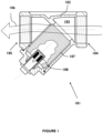
- a strainer 101 is shown in Figures 1 to 4 .
- the strainer 101 is suitable for use in fluid piping, for example fluid circuit piping of a heating or cooling system.
- strainer 101 comprises a body 102 for connection to connection to a fluid piping inflow conduit and to a fluid piping outflow conduit, as will be described in further detail below with reference to Figure 2 .
- the body 102 defines an interior chamber 103, a fluid inlet port 104 and a fluid outlet port 105.
- the body 102 defines a fluid flow path, indicated by arrow 106, between the fluid inlet port 104 and the fluid outlet port 105 that extends through the interior chamber 103.
- the body 102 is arranged such that fluid, such as circulating liquid of a heating or cooling system, flowing therethrough from the fluid inlet port 104 to the fluid outlet port 105 passes through the interior chamber 103.
- the strainer 101 comprises a screen collector 107.
- the screen collector 107 allows fluid to flow therethrough.
- the screen collector 107 is removably locatable in the body 102. More specifically, and as shown in Figures 1 and 2 , the screen collector 107 is locatable in the interior chamber 103, within the fluid flow path 106.
- the screen collector 107 is locatable within the body 102 such that fluid flowing through the strainer 101 from the fluid inlet port 104 to the fluid outlet port 105 passes through the screen collector 107.
- the screen collector 107 is described in detail below.
- the strainer 101 further comprises a permanent magnet collector 108.
- the permanent magnet collector 108 is removably locatable in the body 102. As shown in Figures 1 and 2 , the permanent magnet collector 108 is positionable to collect magnetic particles from fluid flowing through the interior chamber 103.
- the permanent magnet collector 108 is described in detail below.
- the strainer 101 is arranged to mechanically capture particles having a particle size equal or greater than a predetermined size and to magnetically capture magnetic particles having a particle size less than the predetermined size.
- the predetermined size is 80 microns and particles having a particle size equal or greater than 80 microns are captured by the screen collector 107 and particles having a particle size less than 80 microns are captured by the permanent magnet collector 108. It is to be appreciated that the predetermined size may vary between applications.
- the screen collector 107 is not limited to screening particles that are 80 microns or greater in size.
- the screen collector 107 can be selected to screen particles of a different particle size, for example depending on the particular intended application of the strainer 101.
- the permanent magnet collector thus provides an additional straining effect to that provided by the screen collector.
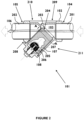
- Strainer 101 is shown installed for use in Figure 2 .
- the body 102 is connected to a fluid piping inflow conduit 201 and to a fluid piping outflow conduit 202. Fluid flowing from the fluid piping inflow conduit 201 to the fluid piping outflow conduit 202 flows through the interior chamber 103 of the body 102.
- the body 102 is made from a non-magnetic material.
- the body 102 is made from a non-magnetic metal, for example stainless steel or brass.
- the body 102 may however be made from any suitable non-magnetic material or combination of non-magnetic materials.
- the screen collector 107 comprises a substantially tubular body 203 having an open fluid inflow end 204.
- the screen collector 107 may take the form of a basket.
- the substantially tubular body 203 is locatable within the fluid flow path 106 such that fluid flowing from the fluid inlet port 104 towards the fluid outlet port 105 enters the substantially tubular body 203 through the open fluid inflow end 204.
- the substantially tubular body 203 is substantially cylindrical.
- the substantially tubular body 203 has a substantially circular shaped cross section, in the direction A-A. It is to be appreciated that in alternative examples the substantially tubular body 203 may have any suitable alternative cross-sectional shape.
- the screen collector 107 defines a plurality of openings 205 dimensioned to capture particles having a particle size equal to or greater than 80 microns.
- the screen collector 107 may however be arranged to capture particles of any suitable alternative size.
- the screen collector 107 is arranged to separate particles of a certain size from fluid flowing through the strainer 101.
- the screen collector 107 comprises a perforated metal sheet screen. It is to be appreciated that the screen collector could comprise any suitable alternative type of screen, for example an expanded metal sheet screen, a welded wire mesh screen, or a woven wire mesh screen. Further, the screen may be made from any suitable material or combination of materials, and is not limited to being made from metal.
- circulating fluid flowing in the fluid piping flows from the fluid piping inflow conduit 201, through the fluid inlet port 104 into the interior chamber 103, through the screen collector 107 and through the fluid outlet port 105 to exit the interior chamber 103 into the fluid piping outflow conduit 202.
- Particles having a particle size that is equal to or greater than a predetermined particle size are collected by the screen collector 107.
- Magnetic particles having a particle size less than the predetermined particle size are collected by the permanent magnet collector 108. It is to be appreciated however that the permanent magnet collector 108 may also collect particles having a particle size that is equal to or greater than the predetermined particle size, as will know be described.
- the substantially tubular body 203 is locatable within the fluid flow path 106 such that fluid flowing from the fluid inlet port 104 towards the fluid outlet port 105 enters the substantially tubular body 203 through the open fluid inflow end 204. It can be seen that the substantially tubular body 203 and the body 102, in particular the internal profile of the body 102, are arranged such that all the fluid entering the strainer 101 must enter the substantially tubular body 203 of the screen collector 107. Any particles in the fluid that are too big to pass through the openings 205 are mechanically captured and retained within the substantially tubular body 203 of the screen collector 107.
- the permanent magnet collector 108 is removably positionable within the substantially tubular body 203 of the screen collector 107. With this arrangement, magnetic particles attracted to the permanent magnet collector 108 are retained within the substantially tubular body 203 of the screen collector 107, along with the particles mechanically captured by the screen collector 107. It is to be appreciated that any suitable alternative relative positioning of the permanent magnet collector 108 and the screen collector 107 may be utilised.
- the screen collector 107 and permanent magnet collector 108 function to remove particles, such as corrosion particles, from contaminated fluid flowing through the strainer 101, such that fluid exits the interior chamber 103 cleaner than when it entered the interior chamber 103.
- using the strainer 101 upstream of an item of equipment functions to prevent contaminant particles from flowing to that item of equipment.
- the strainer 101 further comprises a permanent magnet collector housing 206 made from a non-magnetic material in which the permanent magnet collector 108 is located.
- the permanent magnet collector 108 is removably located in the permanent magnet collector housing 206.
- the permanent magnet collector housing 206 advantageously maintains the permanent magnet collector 108 in a dry condition.
- the permanent magnet collector housing 206 beneficially protects the permanent magnet collector 108 from detrimental effects of exposure to system fluid flowing through the interior chamber 103.
- the permanent magnet collector housing may be made from any suitable non-magnetic material or combination of non-magnetic materials.
- the body 102 defines a collector port 208 open to the interior chamber 103 through which the screen collector 107 and the permanent magnet collector 108 can be removably inserted into the body 102.
- the body 102 has a Y-shape.
- a first branch 209 of the Y-shape comprises the fluid inlet port 104
- a second branch 210 of the Y-shape comprises the fluid outlet port 105
- a third branch 21 I of the Y-shape comprises the collector port 208.
- the fluid inlet port 104 and the fluid outlet port 105 are aligned, with the first and second branches 209, 210 of the Y-shape being arranged linearly
- the third branch 211 extends outwardly from a position intermediate the fluid inlet and outlet ports 104, 105.
- the body 102 comprises an internal annular shoulder 211 against which the substantially tubular body 203 of the screen collector 107 abuts.
- the interior chamber 103 is, in effect, divided into three zones - a first zone upstream of the screen collector 107, a second zone occupied by the substantially tubular body 203 of the screen collector 107 and a third zone downstream of the screen collector 107.
- the strainer 101 is shown installed between the fluid piping inflow and outflow conduits 201, 202 such that the first and second branches 209, 210 of the Y-shaped body 102 are in a generally orientation along a virtual horizontal line and the third branch 211 of the Y-shaped body 102 points downwardly from the virtual horizontal line. With this orientation, gravity assists with the retention of collected particles within the substantially tubular body 203 of the screen collector 107.
- the strainer 101 comprises a collector port cap assembly 301.
- the collector port cap assembly 301 comprises a first cap 302 and a second cap 303.
- the first cap 302 is releasably engageable with the body 102 to selectively seal the collector port 208.
- the first cap 302 is made from a non-magnetic material and comprises a permanent magnet collector housing chamber 304 into which the permanent magnet collector 108 is removably locatable.
- the second cap 303 is releasably engageable with the first cap 302 to selectively seal the permanent magnet collector housing chamber 304 and is made from a non-magnetic material.
- the first cap 302 may be releasably engageable with the body 102 by any suitable engagement arrangement, for example a co-operating screw thread arrangement or a snap-fit arrangement.
- the second cap 303 may be releasably engageable with the first cap 302 by any suitable engagement arrangement, for example a co-operating screw thread arrangement or a snap-fit arrangement.
- the first cap 302 and the second cap 303 may each be made from any suitable non-magnetic material or combination of non-magnetic materials. Each of the first cap 302 and the second cap 303 may be made from a plastics material. The first cap 302 and the second cap 303 may be made from the same, or different, plastics material.
- the permanent magnet collector housing chamber 304 is positioned centrally of the first cap 302.
- the permanent magnet collector housing chamber 304 may be positioned at any suitable alternative site.
- the permanent magnet collector housing chamber 304 has an external surface 305.
- a fixing element 306 for releasably securing the permanent magnet collector 108 to the second cap 303 is provided.
- the fixing element 306 is a screw. Any suitable alternative fixing element, elements or arrangement may be utilised.
- the second cap 303 with permanent magnet collector 108 secured thereto forms a cap and magnet assembly 401.
- the cap and magnet assembly 401 is removable from the first cap 302.
- the first cap 302 can be disengaged from the second cap 303 and then moved away from the second cap 303 to withdraw the permanent magnet collector 108 from the permanent magnet collector housing chamber 304 of the first cap 302.
- the cap and magnet assembly 401 can beneficially be detached from the first cap 302 while the first cap 302 is secured to the body 102 of the strainer 101.
- the permanent magnet collector housing chamber 304 being integral to the first cap 302, which, in use, seals the collector port 208 of the body 102, the permanent magnet collector 108 can thus be withdrawn from the body 102 without unsealing the collector port 208.
- Figure 5 shows a cap and magnet assembly 501.
- a strainer 601 is shown in Figure 6 .
- Strainer 601 of Figure 6 is similar to strainer 101 of Figure 1 but comprises the cap and magnet assembly 501 of Figure 5 instead of the cap and magnet assembly 401 of Figure 4 .
- the cap and magnet assembly 501 of Figure 5 is similar to the cap and magnet assembly 401 of Figure 4 and will now be described with reference to Figure 5 and Figure 6 .
- Cap and magnet assembly 501 comprises a second cap 502 and a permanent magnet collector 503.
- the first cap 502 is made from non-magnetic material.
- the permanent magnet collector 503 is releasably securable to the second cap 502.
- the cap and magnet assembly 501 comprises a reusable fixing 504 for releasably securing the permanent magnet collector 503 to the second cap 502.
- the second cap 502 comprises an engagement portion for use in releasably engaging the second cap 502 with the first cap 302 of the strainer 601.
- the second cap 502 comprises an external screw thread 505 for co-operating with an internal screw thread 602 of the first cap 302.
- the second cap 502 comprises a collar 506. When the second cap 502 of the cap and magnet assembly 501 is engaged with the first cap 302, as shown in Figure 6 , the collar 506 is positioned up towards the exterior of the first cap 302.
- the second cap 502 comprises an internal extension portion 508, which extends to the side of the collar 506 that is presented to the first cap 302 when the second cap 502 is being engaged therewith.
- the internal extension portion 508 is dimensioned to extend into the permanent magnet collector housing chamber 304 of the first cap 302 when the second cap 502 is secured therewith.
- the second cap 502 extends into the permanent magnet collector housing chamber 304 when engaged with the first cap 302.
- Permanent magnet collector 503 has a first end 509, a second end 510, and a side wall 511 extending between the first and second ends 509, 510.
- the permanent magnet collector 503 is removably locatable within the permanent magnet collector housing chamber 304 such that both the first end 509 and the second end 510 are positioned within the interior chamber 103 of the body 102.
- the magnetic field present all around the permanent magnet collector 503 is exerted within the interior chamber 103. More specifically, with the illustrated arrangement of strainer 601, the magnetic field applied by the permanent magnet collector 503 within the screen collector 107 is optimised. In addition, the size of the permanent magnet collector 108 can be effectively minimised.
- the permanent magnet collector 503 is detachably attachable to free end 512 of the internal extension portion 508 of the second cap 502.
- the permanent magnet collector 503 is displaced from the underside of the collar 506 of the second cap 502 a distance 603 by the non-magnetic internal extension portion 508.
- the internal extension portion 508 ensures that the permanent magnet collector 503 is inserted to the desired position within the permanent magnet collector housing chamber 304 when the second cap 502 is engaged with the first cap 302.
- the use of the internal extension portion 508 ensures that magnetic material is not utilised within the strainer 601 at a position in which the effect of the associated magnetic field on magnetic particles within fluid flowing the internal chamber 103 thereof is relatively insignificant.
- the second cap 502 further comprises an external extension portion 507, which extends to the opposite side of the collar 506 and that remains outside of the first cap 302 when the second cap 502 is engaged therewith.
- the external extension portion 507 is profiled to allow a tool to be used thereon to facilitate engagement of the second cap 502 with the first cap 302.
- the external extension portion 507 may be profiled as a hexagonal head, with which a suitable socket can be used to effect rotation of the second cap 502.
- the strainer 101 may be provided with any suitable arrangement for use in connecting the body 102 to a fluid piping inflow conduit and to a fluid piping outflow conduit.
- the body 102 is provided with first and second connection screw threads 307, 308 for use in connecting the body 102 to a fluid piping inflow conduit and to a fluid piping outflow conduit.
- the body 102 is provided with first and second connection flanges for use in connecting the body 102 to a fluid piping inflow conduit and to a fluid piping outflow conduit
- a strainer as described herein may have an alternative arrangement to that illustrated.
- the body may define a collector port that is selectively sealable with a cap that does not form or comprise a permanent magnet collector housing chamber, in which case a separate permanent magnet collector housing may be provided.
- Fluid piping may be provided with one or more of strainers as described herein.
- strainers as described herein are usable in fluid circuit piping of a heating or cooling system, to protect one or more items of equipment, such as a pump, from contaminant particles in the circulating system water.
- the method involves the steps of receiving strainer 101, connecting the body 102 of the strainer 101 to a fluid piping inflow conduit of the fluid piping and connecting the body 102 of the strainer 101 to a fluid piping outflow conduit of the fluid piping.
- the method also involves the steps of locating the screen collector 107 within the body 102 of the strainer 101 and locating the permanent magnet collector 108 within the body of the strainer 101. It is to be appreciated that as the screen collector 107 and permanent magnet collector 108 are removably locatable within the body 102 of the strainer 101, the above-mentioned steps may be performed in any suitable order.
- the screen collector 107 and permanent magnet collector 108 may be located within the body 102 of the strainer 101 before or after the body 102 of the strainer 101 is connected between fluid piping inflow and outflow conduits.
- a method of treating fluid of fluid piping involves the steps of identifying a strainer 101 that is installed within fluid piping following the method of installing fluid treatment apparatus in fluid piping described above, stopping fluid flow into the body 102, removing, cleaning and replacing the screen collector 107, removing, cleaning and replacing the permanent magnet collector 108, and restarting a fluid flow into the body 102.
- the method of treatment provided by the strainer 101 is that of particle capturing and regular cleaning of the screen and permanent magnet collectors 107,108 ensures operational efficiency of the strainer 101 in capturing particles from the fluid flow and improves operational efficiency of the system.
- particles having a particle size equal to or greater than a predetermined size that enter into the strainer 101 with the circulating fluid are captured by the screen collector 107. These mechanically captured particles are retained in the interior chamber 103 until subsequently removed. Further, during normal operation of the strainer 101, magnetic particles are attracted by the permanent magnet collector 108 and collect on the external surface 305 of the permanent magnet collector housing chamber 304 that is exposed to the circulating fluid (wet side of first cap 302). These magnetically captured particles are retained in the interior chamber 103 until subsequently removed.
- the strainer 101 is isolated from fluid flow. Thus, the circulation of the system fluid into the strainer 101 is stopped.
- the first cap 302 is then removed from the body 102. Any magnetic detritus collected will be present on the external surface 305 of the permanent magnet collector housing chamber 304.
- the second cap 303 is then removed from the first cap 302, which has the effect of withdrawing the permanent magnet collector 108 from the permanent magnetic collector housing chamber 304. This removes the magnetic field previously applied by permanent magnet collector 108 to hold the collected magnetic particles on the external surface 305 of the permanent magnetic collector housing chamber 304. With the magnetic field now absent, the collected magnetic particles fall away from the first cap 302.
- the first cap 302 can be rinsed to ensure proper cleanliness, and the second cap 303 can then be replaced to seal the permanent magnet collector 108 within the permanent magnetic collector housing chamber 304.
- the screen collector 107 can be withdrawn through the collector port 208 and rinsed clean.
- the cleaned screen collector 107 can then be replaced in the interior chamber 103.
- the collector port cap assembly 301 can be reconnected to the body 102 to seal the collector port 208.
- the strainer 101 may then be opened back to the system flow. It is to be appreciated that the screen and permanent magnet collectors 107, 108 may be cleaned in any chronological order.
- the screen and permanent magnet collectors 107, 108 of the strainer 101 may be substituted, for example to change the size of the openings of the screen collector or the magnetic field applied by the permanent magnet collector.
- the strainer of the present invention is thus environmentally advantageous.
- a strainer as described herein may have any suitable dimensions, any suitable appearance, may be made from any suitable materials or combination of materials and may be made using any suitable method, process or technique or any suitable combination of methods, processes or techniques. It is thus to be understood that any suitable material fabrication, construction and method of manufacture may be used. A strainer as described herein may be used in any suitable application.
Landscapes
- Engineering & Computer Science (AREA)
- Chemical & Material Sciences (AREA)
- Chemical Kinetics & Catalysis (AREA)
- General Engineering & Computer Science (AREA)
- Water Supply & Treatment (AREA)
- Mechanical Engineering (AREA)
- Life Sciences & Earth Sciences (AREA)
- Hydrology & Water Resources (AREA)
- Environmental & Geological Engineering (AREA)
- Organic Chemistry (AREA)
- Combustion & Propulsion (AREA)
- Physics & Mathematics (AREA)
- Thermal Sciences (AREA)
- Filtration Of Liquid (AREA)
- Water Treatment By Electricity Or Magnetism (AREA)
Description
- The present invention relates to fluid treatment, in particular to a strainer for use in fluid piping, for example fluid circuit piping of a heating or cooling system.
- Known heating and cooling systems comprise a fluid circuit through which a fluid circulates under pressure. An example of this type of system is a closed circuit central heating system, in which system water flows in a loop from a boiler, through a series of radiators or heat emitters, and then back to the boiler.
- Systems of this type are typically manufactured from steel and other common metals. In such systems, material surfaces are exposed to the circulated fluid. A problem that is commonly associated that these systems is the corrosion of metal that is in contact with the system fluid.
- System corrosion results in contamination of the circulated water with corrosion particles, such as rust, detritus and other undesirable debris. The presence of corrosion particles within the circulated liquid negatively impacts system performance and causes damage. Unless the corrosion particles are captured and removed from the contaminated circulated liquid, system components can become clogged or blocked, leading to a significant loss of system efficiency, further system deterioration from leaks, and eventually total system failure.
- When the performance efficiency of a heating or cooling system reduces due to the effects of corrosion contamination, both the amount of energy required to operate the system and the amount of carbon dioxide (CO2) emitted by the system increases. It is therefore desirable from economic and environmental perspectives to prevent or inhibit the detrimental effect of corrosion particles within the circulating liquid.
- A known device for use in removing corrosion particles from the circulating fluid is a strainer (also termed a pipeline strainer). The strainer is connected to the fluid circuit piping, directly in-line with the fluid flow, and functions to mechanically remove unwanted solids from the system fluid. When installed, fluid flows through a screen within the strainer, which acts as a physical filter. Particles in the system fluid that are over a certain size are trapped by the screen, and captured particles are retained within the strainer for subsequent removal.
- Strainers are typically installed upstream of equipment to be protected. For example, a strainer may be installed upstream of a pump to prevent larger pieces of debris from fouling the impeller, which could result in a blockage or damage. By way of further example, a strainer may be used upstream of a boiler, a heat exchanger, or a large and/or expensive item in a system.
- A first type of prior art strainer is known as a Y-type strainer. The body of a Y-type strainer has first and second branches providing an inlet and an outlet, and a third intermediate branch providing a pocket for a screen that intersects the fluid flow path between the inlet and outlet, such that fluid flowing through the body passes through the screen. The screen is typically cylindrical and made from a metal perforated sheet or mesh. In use, fluid flows into an open end of the cylindrical screen and any particles that are too big to flow through the openings, such as rust and detritus particles, are trapped inside for subsequent removal. In this way, contaminant particles over a certain size are separated from the circulating fluid as it flows through the strainer. Over time, however, the particles captured within the cylindrical screen build up and inhibit throughflow. To prevent problems arising from clogging or blocking of the screen by caught particles, routine maintenance is required to remove the collected detritus from within the strainer. However, unlike some filters, the screen can be cleaned and reused.
- A typical screen has openings dimensioned to prevent passage therethrough of particles having a particle size equal to or greater than 80 microns. Therefore, particles having a particle size less than 80 microns are not prevented from flowing through the strainer and back into circulation. It is known for these smaller particles to settle in 'low flow' areas, for example at the bottom of radiators and pipes of a heating system. Further, it is known for rust particles, which are relatively very small, to combine with scale deposits to form a sludge-like substance (generally termed sludge). This is particularly prevalent in areas of particle settlement. Sludge is a common problem within heating systems, and can block pipework and develop into large clumps in the bottom of radiators. Sludge deposits or clumps at the lower end of a radiator cause a localised reduction in heat transmission (known in the industry as a cold spot). The presence of such cold spots increases energy usage and places the system under operational strain.
- Japanese Patent Publication No.
JP 2010 279886 A - According to a first aspect there is provided a strainer for use in fluid piping, said strainer comprising: a body for connection to a fluid piping inflow conduit and to a fluid piping outflow conduit, the body defining an interior chamber, a fluid inlet port and a fluid outlet port, and the body defining a fluid flow path between the fluid inlet port and the fluid outlet port that extends through the interior chamber; a screen collector removably locatable in the body, within the fluid flow path; and a permanent magnet collector removably locatable in the body; said body defining a collector port open to the interior chamber through which the screen collector and the permanent magnet collector can be removably inserted into the body; and the strainer comprises a first cap releasably engageable with the body to selectively seal the collector port, the first cap made from a non-magnetic material and defining a permanent magnet collector housing chamber into which the permanent magnet collector is removably locatable; characterised in that: the strainer further comprises a second cap releasably engageable with the first cap to selectively seal the permanent magnet collector housing chamber and form a collector port cap assembly that is releasably engageable with the body of the strainer by releasably engaging the first cap to the body to seal the collector port, the second cap made from a non-magnetic material; and said permanent magnet collector is releasably securable to said second cap to form a cap and magnet assembly that is detachable from the first cap while the first cap is secured to the body of the strainer.
- The screen collector may comprise a substantially tubular body having an open fluid inflow end, the substantially tubular body locatable within the fluid flow path such that fluid flowing from the fluid inlet port towards the fluid outlet port enters the substantially tubular body through the open fluid inflow end.
- The permanent magnet collector may be removably positionable within the substantially tubular body of the screen collector.
- The screen collector may define a plurality of openings dimensioned to capture particles having a particle size equal to or greater than 80 microns.
- The body may have a Y-shape, and in which a first branch of the Y-shape comprises the fluid inlet port, a second branch of the Y-shape comprises the fluid outlet port and a third branch of the Y-shape comprises the collector port.
- A fixing element may be provided for releasably securing the permanent magnet collector to the second cap.
- The second cap may extend into the permanent magnet collector housing chamber of the first cap when the second cap is engaged with the first cap.
- The permanent magnet may have a first end, a second end and a side wall extending between the first end and the second end, and the permanent magnet may be removably locatable within the permanent magnet collector housing chamber such that that the first end and the second end are positioned within the interior chamber of the body.
- The body may be provided with first and second connection screw threads, or with first and second connection flanges, for use in connecting the body to a fluid piping inflow conduit and to a fluid piping outflow conduit.
- According to a second aspect, a strainer according to the first aspect is used in fluid circuit piping of a heating or cooling system.
- According to a third aspect there is provided fluid piping provided with a strainer according to the first aspect.
- The invention advantageously provides a pipe line strainer with both a mechanical and a magnetic collector.
- Further particular and preferred aspects of the invention are set out in the accompanying dependent claims.
- The present invention will now be more particularly described, with reference to the accompanying drawings, in which:
-
Figure 1 shows a strainer for use in fluid piping, in a fully assembled condition; -
Figure 2 shows the strainer ofFigure 1 installed in fluid piping; -
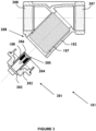
Figure 3 shows the strainer ofFigure 1 , in a partially assembled condition; -
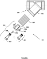
Figure 4 shows the strainer ofFigure 1 , in a fully disassembled condition; -
Figure 5 shows a cap and magnet assembly; and -
Figure 6 shows the cap and magnet assembly ofFigure 5 arranged for use. - Example embodiments are described below in sufficient detail to enable those of ordinary skill in the art to embody and implement the apparatus, systems and processes described herein. It is to be understood that embodiments can be provided in many alternate forms and the invention should not be construed as limited to the examples set forth herein but by the scope of the appended claims.
- A
strainer 101 is shown inFigures 1 to 4 . Thestrainer 101 is suitable for use in fluid piping, for example fluid circuit piping of a heating or cooling system. - In
Figures 1 and2 , thestrainer 101 is shown in a fully assembled condition. - Referring to
Figure 1 ,strainer 101 comprises abody 102 for connection to connection to a fluid piping inflow conduit and to a fluid piping outflow conduit, as will be described in further detail below with reference toFigure 2 . - The
body 102 defines aninterior chamber 103, afluid inlet port 104 and afluid outlet port 105. Thebody 102 defines a fluid flow path, indicated byarrow 106, between thefluid inlet port 104 and thefluid outlet port 105 that extends through theinterior chamber 103. Thebody 102 is arranged such that fluid, such as circulating liquid of a heating or cooling system, flowing therethrough from thefluid inlet port 104 to thefluid outlet port 105 passes through theinterior chamber 103. - The
strainer 101 comprises ascreen collector 107. Thescreen collector 107 allows fluid to flow therethrough. Thescreen collector 107 is removably locatable in thebody 102. More specifically, and as shown inFigures 1 and2 , thescreen collector 107 is locatable in theinterior chamber 103, within thefluid flow path 106. Thescreen collector 107 is locatable within thebody 102 such that fluid flowing through thestrainer 101 from thefluid inlet port 104 to thefluid outlet port 105 passes through thescreen collector 107. Thescreen collector 107 is described in detail below. - The
strainer 101 further comprises apermanent magnet collector 108. Thepermanent magnet collector 108 is removably locatable in thebody 102. As shown inFigures 1 and2 , thepermanent magnet collector 108 is positionable to collect magnetic particles from fluid flowing through theinterior chamber 103. Thepermanent magnet collector 108 is described in detail below. - The
strainer 101 is arranged to mechanically capture particles having a particle size equal or greater than a predetermined size and to magnetically capture magnetic particles having a particle size less than the predetermined size. In an example, the predetermined size is 80 microns and particles having a particle size equal or greater than 80 microns are captured by thescreen collector 107 and particles having a particle size less than 80 microns are captured by thepermanent magnet collector 108. It is to be appreciated that the predetermined size may vary between applications. Thus, thescreen collector 107 is not limited to screening particles that are 80 microns or greater in size. Thescreen collector 107 can be selected to screen particles of a different particle size, for example depending on the particular intended application of thestrainer 101. - The permanent magnet collector thus provides an additional straining effect to that provided by the screen collector.
-
Strainer 101 is shown installed for use inFigure 2 . As illustrated, thebody 102 is connected to a fluidpiping inflow conduit 201 and to a fluidpiping outflow conduit 202. Fluid flowing from the fluidpiping inflow conduit 201 to the fluidpiping outflow conduit 202 flows through theinterior chamber 103 of thebody 102. - The
body 102 is made from a non-magnetic material. In an example, thebody 102 is made from a non-magnetic metal, for example stainless steel or brass. Thebody 102 may however be made from any suitable non-magnetic material or combination of non-magnetic materials. - According to the specific illustrated embodiment, the
screen collector 107 comprises a substantiallytubular body 203 having an openfluid inflow end 204. Thescreen collector 107 may take the form of a basket. As shown, the substantiallytubular body 203 is locatable within thefluid flow path 106 such that fluid flowing from thefluid inlet port 104 towards thefluid outlet port 105 enters the substantiallytubular body 203 through the openfluid inflow end 204. - In this example, the substantially
tubular body 203 is substantially cylindrical. The substantiallytubular body 203 has a substantially circular shaped cross section, in the direction A-A. It is to be appreciated that in alternative examples the substantiallytubular body 203 may have any suitable alternative cross-sectional shape. - In this example, the
screen collector 107 defines a plurality ofopenings 205 dimensioned to capture particles having a particle size equal to or greater than 80 microns. Thescreen collector 107 may however be arranged to capture particles of any suitable alternative size. Thescreen collector 107 is arranged to separate particles of a certain size from fluid flowing through thestrainer 101. - In this example, the
screen collector 107 comprises a perforated metal sheet screen. It is to be appreciated that the screen collector could comprise any suitable alternative type of screen, for example an expanded metal sheet screen, a welded wire mesh screen, or a woven wire mesh screen. Further, the screen may be made from any suitable material or combination of materials, and is not limited to being made from metal. - The
screen collector 107 may define any suitable number ofopenings 205, which may be any suitable size and shape and which may include openings of different sizes and/or shapes. - In this example, the
permanent magnet collector 108 comprises a rare-earth magnet. Thepermanent magnet collector 108 may comprise an alternative type of magnet, for example a ferrite or AlNiCo type magnet. Thepermanent magnet collector 108 may comprise one or more magnets. Thepermanent magnet collector 108 is arranged to separate magnetic particles from fluid flowing through thestrainer 101. - During use of the
strainer 101, circulating fluid flowing in the fluid piping flows from the fluidpiping inflow conduit 201, through thefluid inlet port 104 into theinterior chamber 103, through thescreen collector 107 and through thefluid outlet port 105 to exit theinterior chamber 103 into the fluidpiping outflow conduit 202. - As the fluid flows through the
strainer 101, particles in the fluid are captured in theinterior chamber 103. - Particles having a particle size that is equal to or greater than a predetermined particle size are collected by the
screen collector 107. Magnetic particles having a particle size less than the predetermined particle size are collected by thepermanent magnet collector 108. It is to be appreciated however that thepermanent magnet collector 108 may also collect particles having a particle size that is equal to or greater than the predetermined particle size, as will know be described. - As shown, in the illustrated embodiment, the substantially
tubular body 203 is locatable within thefluid flow path 106 such that fluid flowing from thefluid inlet port 104 towards thefluid outlet port 105 enters the substantiallytubular body 203 through the openfluid inflow end 204. It can be seen that the substantiallytubular body 203 and thebody 102, in particular the internal profile of thebody 102, are arranged such that all the fluid entering thestrainer 101 must enter the substantiallytubular body 203 of thescreen collector 107. Any particles in the fluid that are too big to pass through theopenings 205 are mechanically captured and retained within the substantiallytubular body 203 of thescreen collector 107. - In this illustrated embodiment, the
permanent magnet collector 108 is removably positionable within the substantiallytubular body 203 of thescreen collector 107. With this arrangement, magnetic particles attracted to thepermanent magnet collector 108 are retained within the substantiallytubular body 203 of thescreen collector 107, along with the particles mechanically captured by thescreen collector 107. It is to be appreciated that any suitable alternative relative positioning of thepermanent magnet collector 108 and thescreen collector 107 may be utilised. - The
screen collector 107 andpermanent magnet collector 108 function to remove particles, such as corrosion particles, from contaminated fluid flowing through thestrainer 101, such that fluid exits theinterior chamber 103 cleaner than when it entered theinterior chamber 103. Thus, using thestrainer 101 upstream of an item of equipment functions to prevent contaminant particles from flowing to that item of equipment. - In this embodiment, the
strainer 101 further comprises a permanentmagnet collector housing 206 made from a non-magnetic material in which thepermanent magnet collector 108 is located. Preferably, and in this example, thepermanent magnet collector 108 is removably located in the permanentmagnet collector housing 206. The permanentmagnet collector housing 206 advantageously maintains thepermanent magnet collector 108 in a dry condition. The permanentmagnet collector housing 206 beneficially protects thepermanent magnet collector 108 from detrimental effects of exposure to system fluid flowing through theinterior chamber 103. The permanent magnet collector housing may be made from any suitable non-magnetic material or combination of non-magnetic materials. - In
Figure 2 ,particles 207 are shown collected around the permanentmagnet collector housing 206 due to a magnetic attraction between theparticles 207 and thepermanent magnet collector 108 located within the permanentmagnet collector housing 206. - In this illustrated embodiment, the
body 102 defines acollector port 208 open to theinterior chamber 103 through which thescreen collector 107 and thepermanent magnet collector 108 can be removably inserted into thebody 102. - According to the present embodiment, the
body 102 has a Y-shape. Afirst branch 209 of the Y-shape comprises thefluid inlet port 104, asecond branch 210 of the Y-shape comprises thefluid outlet port 105 and a third branch 21 I of the Y-shape comprises thecollector port 208. In this illustrated example, thefluid inlet port 104 and thefluid outlet port 105 are aligned, with the first andsecond branches third branch 211 extends outwardly from a position intermediate the fluid inlet andoutlet ports - In the shown arrangement, the
body 102 comprises an internalannular shoulder 211 against which the substantiallytubular body 203 of thescreen collector 107 abuts. When thescreen collector 107 is located within thebody 102 as shown, theinterior chamber 103 is, in effect, divided into three zones - a first zone upstream of thescreen collector 107, a second zone occupied by the substantiallytubular body 203 of thescreen collector 107 and a third zone downstream of thescreen collector 107. - In
Figure 2 , thestrainer 101 is shown installed between the fluid piping inflow andoutflow conduits second branches body 102 are in a generally orientation along a virtual horizontal line and thethird branch 211 of the Y-shapedbody 102 points downwardly from the virtual horizontal line. With this orientation, gravity assists with the retention of collected particles within the substantiallytubular body 203 of thescreen collector 107. - Further features of the present embodiment will now be described with reference to
Figures 3 and4 . - The
strainer 101 comprises a collectorport cap assembly 301. In this illustrated example, the collectorport cap assembly 301 comprises afirst cap 302 and asecond cap 303. Thefirst cap 302 is releasably engageable with thebody 102 to selectively seal thecollector port 208. Thefirst cap 302 is made from a non-magnetic material and comprises a permanent magnetcollector housing chamber 304 into which thepermanent magnet collector 108 is removably locatable. Thesecond cap 303 is releasably engageable with thefirst cap 302 to selectively seal the permanent magnetcollector housing chamber 304 and is made from a non-magnetic material. - The
first cap 302 may be releasably engageable with thebody 102 by any suitable engagement arrangement, for example a co-operating screw thread arrangement or a snap-fit arrangement. Thesecond cap 303 may be releasably engageable with thefirst cap 302 by any suitable engagement arrangement, for example a co-operating screw thread arrangement or a snap-fit arrangement. - The
first cap 302 and thesecond cap 303 may each be made from any suitable non-magnetic material or combination of non-magnetic materials. Each of thefirst cap 302 and thesecond cap 303 may be made from a plastics material. Thefirst cap 302 and thesecond cap 303 may be made from the same, or different, plastics material. - In the illustrated example, the permanent magnet
collector housing chamber 304 is positioned centrally of thefirst cap 302. The permanent magnetcollector housing chamber 304 may be positioned at any suitable alternative site. As shown, the permanent magnetcollector housing chamber 304 has anexternal surface 305. - In this illustrated example, a fixing
element 306 for releasably securing thepermanent magnet collector 108 to thesecond cap 303 is provided. In this example, the fixingelement 306 is a screw. Any suitable alternative fixing element, elements or arrangement may be utilised. - The
second cap 303 withpermanent magnet collector 108 secured thereto forms a cap andmagnet assembly 401. The cap andmagnet assembly 401 is removable from thefirst cap 302. According to the shown example, thefirst cap 302 can be disengaged from thesecond cap 303 and then moved away from thesecond cap 303 to withdraw thepermanent magnet collector 108 from the permanent magnetcollector housing chamber 304 of thefirst cap 302. The cap andmagnet assembly 401 can beneficially be detached from thefirst cap 302 while thefirst cap 302 is secured to thebody 102 of thestrainer 101. With the permanent magnetcollector housing chamber 304 being integral to thefirst cap 302, which, in use, seals thecollector port 208 of thebody 102, thepermanent magnet collector 108 can thus be withdrawn from thebody 102 without unsealing thecollector port 208. -
Figure 5 shows a cap andmagnet assembly 501. Astrainer 601 is shown inFigure 6 .Strainer 601 ofFigure 6 is similar tostrainer 101 ofFigure 1 but comprises the cap andmagnet assembly 501 ofFigure 5 instead of the cap andmagnet assembly 401 ofFigure 4 . The cap andmagnet assembly 501 ofFigure 5 is similar to the cap andmagnet assembly 401 ofFigure 4 and will now be described with reference toFigure 5 and Figure 6 . - Cap and
magnet assembly 501 comprises asecond cap 502 and apermanent magnet collector 503. Thefirst cap 502 is made from non-magnetic material. In this example, thepermanent magnet collector 503 is releasably securable to thesecond cap 502. In this example, the cap andmagnet assembly 501 comprises a reusable fixing 504 for releasably securing thepermanent magnet collector 503 to thesecond cap 502. Thesecond cap 502 comprises an engagement portion for use in releasably engaging thesecond cap 502 with thefirst cap 302 of thestrainer 601. According to the present example, thesecond cap 502 comprises anexternal screw thread 505 for co-operating with aninternal screw thread 602 of thefirst cap 302. Thesecond cap 502 comprises acollar 506. When thesecond cap 502 of the cap andmagnet assembly 501 is engaged with thefirst cap 302, as shown inFigure 6 , thecollar 506 is positioned up towards the exterior of thefirst cap 302. - As illustrated, the
second cap 502 comprises aninternal extension portion 508, which extends to the side of thecollar 506 that is presented to thefirst cap 302 when thesecond cap 502 is being engaged therewith. Theinternal extension portion 508 is dimensioned to extend into the permanent magnetcollector housing chamber 304 of thefirst cap 302 when thesecond cap 502 is secured therewith. Thus, thesecond cap 502 extends into the permanent magnetcollector housing chamber 304 when engaged with thefirst cap 302. -
Permanent magnet collector 503 has afirst end 509, asecond end 510, and aside wall 511 extending between the first and second ends 509, 510. In the present example, and as can be seen inFigure 6 , thepermanent magnet collector 503 is removably locatable within the permanent magnetcollector housing chamber 304 such that both thefirst end 509 and thesecond end 510 are positioned within theinterior chamber 103 of thebody 102. As a result, the magnetic field present all around thepermanent magnet collector 503 is exerted within theinterior chamber 103. More specifically, with the illustrated arrangement ofstrainer 601, the magnetic field applied by thepermanent magnet collector 503 within thescreen collector 107 is optimised. In addition, the size of thepermanent magnet collector 108 can be effectively minimised. - In the shown example, the
permanent magnet collector 503 is detachably attachable tofree end 512 of theinternal extension portion 508 of thesecond cap 502. When the cap andmagnet assembly 501 is received within thefirst cap 302, thepermanent magnet collector 503 is displaced from the underside of thecollar 506 of the second cap 502 adistance 603 by the non-magneticinternal extension portion 508. Theinternal extension portion 508 ensures that thepermanent magnet collector 503 is inserted to the desired position within the permanent magnetcollector housing chamber 304 when thesecond cap 502 is engaged with thefirst cap 302. The use of theinternal extension portion 508 ensures that magnetic material is not utilised within thestrainer 601 at a position in which the effect of the associated magnetic field on magnetic particles within fluid flowing theinternal chamber 103 thereof is relatively insignificant. - In this example also, the
second cap 502 further comprises anexternal extension portion 507, which extends to the opposite side of thecollar 506 and that remains outside of thefirst cap 302 when thesecond cap 502 is engaged therewith. In this specific example, theexternal extension portion 507 is profiled to allow a tool to be used thereon to facilitate engagement of thesecond cap 502 with thefirst cap 302. Theexternal extension portion 507 may be profiled as a hexagonal head, with which a suitable socket can be used to effect rotation of thesecond cap 502. - The
strainer 101 may be provided with any suitable arrangement for use in connecting thebody 102 to a fluid piping inflow conduit and to a fluid piping outflow conduit. In this illustrated example, thebody 102 is provided with first and secondconnection screw threads body 102 to a fluid piping inflow conduit and to a fluid piping outflow conduit. In an alternative example, thebody 102 is provided with first and second connection flanges for use in connecting thebody 102 to a fluid piping inflow conduit and to a fluid piping outflow conduit - It is to be appreciated that a strainer as described herein may have an alternative arrangement to that illustrated. For example, the body may define a collector port that is selectively sealable with a cap that does not form or comprise a permanent magnet collector housing chamber, in which case a separate permanent magnet collector housing may be provided.
- Fluid piping may be provided with one or more of strainers as described herein. For example, strainers as described herein are usable in fluid circuit piping of a heating or cooling system, to protect one or more items of equipment, such as a pump, from contaminant particles in the circulating system water.
- A method of installing fluid treatment apparatus in fluid piping will now be described. The method involves the steps of receiving
strainer 101, connecting thebody 102 of thestrainer 101 to a fluid piping inflow conduit of the fluid piping and connecting thebody 102 of thestrainer 101 to a fluid piping outflow conduit of the fluid piping. The method also involves the steps of locating thescreen collector 107 within thebody 102 of thestrainer 101 and locating thepermanent magnet collector 108 within the body of thestrainer 101. It is to be appreciated that as thescreen collector 107 andpermanent magnet collector 108 are removably locatable within thebody 102 of thestrainer 101, the above-mentioned steps may be performed in any suitable order. For example, thescreen collector 107 andpermanent magnet collector 108 may be located within thebody 102 of thestrainer 101 before or after thebody 102 of thestrainer 101 is connected between fluid piping inflow and outflow conduits. - In an application, the fluid piping is fluid circuit piping of a heating or cooling system. In such an application, the strainer is usable to remove contaminants, such as corrosion particles, from the circulating system liquid. In an alternative application, the fluid piping is piping of a fuel line. In such an application, the strainer is usable to remove contaminants from a flow of fuel. The fuel may, for example, be petrol.
- A method of treating fluid of fluid piping will now be described. The method involves the steps of identifying a
strainer 101 that is installed within fluid piping following the method of installing fluid treatment apparatus in fluid piping described above, stopping fluid flow into thebody 102, removing, cleaning and replacing thescreen collector 107, removing, cleaning and replacing thepermanent magnet collector 108, and restarting a fluid flow into thebody 102. The method of treatment provided by thestrainer 101 is that of particle capturing and regular cleaning of the screen and permanent magnet collectors 107,108 ensures operational efficiency of thestrainer 101 in capturing particles from the fluid flow and improves operational efficiency of the system. - Routine maintenance of the
strainer 101 will now be described. - During normal operation of the
strainer 101, particles having a particle size equal to or greater than a predetermined size that enter into thestrainer 101 with the circulating fluid are captured by thescreen collector 107. These mechanically captured particles are retained in theinterior chamber 103 until subsequently removed. Further, during normal operation of thestrainer 101, magnetic particles are attracted by thepermanent magnet collector 108 and collect on theexternal surface 305 of the permanent magnetcollector housing chamber 304 that is exposed to the circulating fluid (wet side of first cap 302). These magnetically captured particles are retained in theinterior chamber 103 until subsequently removed. - To remove material collected from the circulating fluid by the
strainer 101, thestrainer 101 is isolated from fluid flow. Thus, the circulation of the system fluid into thestrainer 101 is stopped. Thefirst cap 302 is then removed from thebody 102. Any magnetic detritus collected will be present on theexternal surface 305 of the permanent magnetcollector housing chamber 304. Thesecond cap 303 is then removed from thefirst cap 302, which has the effect of withdrawing thepermanent magnet collector 108 from the permanent magneticcollector housing chamber 304. This removes the magnetic field previously applied bypermanent magnet collector 108 to hold the collected magnetic particles on theexternal surface 305 of the permanent magneticcollector housing chamber 304. With the magnetic field now absent, the collected magnetic particles fall away from thefirst cap 302. Thefirst cap 302 can be rinsed to ensure proper cleanliness, and thesecond cap 303 can then be replaced to seal thepermanent magnet collector 108 within the permanent magneticcollector housing chamber 304. With thefirst cap 302 removed from thebody 102, thescreen collector 107 can be withdrawn through thecollector port 208 and rinsed clean. The cleanedscreen collector 107 can then be replaced in theinterior chamber 103. Following cleaning of thescreen collector 107 and thepermanent magnet collector 108, the collectorport cap assembly 301 can be reconnected to thebody 102 to seal thecollector port 208. Thestrainer 101 may then be opened back to the system flow. It is to be appreciated that the screen andpermanent magnet collectors - It is further to be appreciated that the screen and
permanent magnet collectors strainer 101 may be substituted, for example to change the size of the openings of the screen collector or the magnetic field applied by the permanent magnet collector. - At least the following benefits are associated with the strainer of the present invention:
- Magnetic particles are captured in addition to particles equal to greater than a particular size, which cleans the system flow more quickly
- The capturing of magnetic particles that are smaller in size than the particles captured mechanically reduces the quantity of unwanted particles in the system flow, which provides cleaner system flow
- The capturing of smaller particles reduces the number of particles dropping out of suspension within the system flow into low flow areas, which prevents detritus build up and clumping and, in the application of a heating system, reduces the risk of sludge and cold spots
- The capturing of more particles from the system water improves the operational efficiency of the system (helps achieve the original design efficiency) and reduces the risk of component damage and system failure, which reduces energy and maintenance costs and reduces carbon dioxide (CO2) emissions
- The strainer of the present invention is thus environmentally advantageous.
- A strainer as described herein may have any suitable dimensions, any suitable appearance, may be made from any suitable materials or combination of materials and may be made using any suitable method, process or technique or any suitable combination of methods, processes or techniques. It is thus to be understood that any suitable material fabrication, construction and method of manufacture may be used. A strainer as described herein may be used in any suitable application.
- Although illustrative embodiments of the invention have been disclosed in detail herein, with reference to the accompanying drawings, it is to be understood that the invention is not limited to the precise embodiments shown and that various changes and modifications can be effected therein by one skilled in the art without departing from the scope of the invention as defined by the appended claims.
Claims (15)
- A strainer (101) for use in fluid piping, said strainer (101) comprising:a body (102) for connection to a fluid piping inflow conduit (201) and to a fluid piping outflow conduit (202), the body (102) defining an interior chamber (103), a fluid inlet port (104) and a fluid outlet port (105), and the body (102) defining a fluid flow path (106) between the fluid inlet port (104) and the fluid outlet port (105) that extends through the interior chamber (103);a screen collector removably (107) locatable in the body (102), within the fluid flow path (106); anda permanent magnet collector (108) removably locatable in the body (102);said body (102) defining a collector port (208) open to the interior chamber (103) through which the screen collector (107) and the permanent magnet collector (108) can be removably inserted into the body (102); andthe strainer (101) comprises a first cap (302) releasably engageable with the body (102) to selectively seal the collector port (208), the first cap (302) made from a non-magnetic material and defining a permanent magnet collector housing chamber (304) into which the permanent magnet collector (108) is removably locatable; characterised in that:the strainer (101) further comprises a second cap (303) releasably engageable with the first cap (302) to selectively seal the permanent magnet collector housing chamber (304) and form a collector port cap assembly (301) that is releasably engageable with the body (102) of the strainer (101) by releasably engaging the first cap (302) to the body (102) to seal the collector port (208), the second cap (303) made from a non-magnetic material; andsaid permanent magnet collector (108) is releasably securable to said second cap (303) to form a cap and magnet assembly (401) that is detachable from the first cap (302) while the first cap (302) is secured to the body (102) of the strainer.
- A strainer (101) as claimed in claim 1, further comprising a fixing element (306) for releasably securing the permanent magnet collector (108) to the second cap (303).
- A strainer (101) as claimed in claim 1 or claim 2, wherein said permanent magnet collector (503) has a first end (509), a second end (510), and a side wall (511) extending between said first end (509) and said second end (510), and
said permanent magnet collector (503) is removably locatable within said permanent magnet collector housing chamber (304) such that that said first end (509) and said second end (510) are positioned within the interior chamber (103) of the body (101). - A strainer (101) as claimed in any of claims 1 to 3, wherein said screen collector (107) comprises a substantially tubular body (203) having an open fluid inflow end (204), the substantially tubular body (203) locatable within the fluid flow path (106) such that fluid flowing from the fluid inlet port (104) towards the fluid outlet port (105) enters the substantially tubular body (203) through the open fluid inflow end (204).
- A strainer (101) as claimed in claim 4, wherein said substantially tubular body (204) is substantially cylindrical.
- A strainer (101) as claimed in claim 5, wherein said permanent magnet collector (108) is removably positionable within the substantially tubular body (203) of the screen collector (107).
- A strainer (101) as claimed in any of claims 1 to 6, wherein said screen collector (107) defines a plurality of openings (205) dimensioned to capture particles having a particle size equal to or greater than 80 microns.
- A strainer (101) as claimed in any of claims 1 to 7, wherein the body (102) has a Y-shape, and in which a first branch (209) of the Y-shape comprises the fluid inlet port (104), a second branch (210) of the Y-shape comprises the fluid outlet port (105) and a third branch (211) of the Y-shape comprises the collector port (208).
- A strainer (101) as claimed in any of claims 1 to 8, wherein said permanent magnet collector comprises a rare-earth magnet.
- A strainer (101) as claimed in any of claims 1 to 9, wherein said screen collector (107) comprises a perforated metal sheet screen.
- A strainer (101) as claimed in any of claims 1 to 10, wherein said body (102) is provided with one of the following for use in connecting the body (102) to a fluid piping inflow conduit (201) and to a fluid piping outflow conduit (202): first and second connection screw threads, first and second connection flanges.
- A strainer (101) as claimed in any of claims 1 to 11, wherein said first cap (302) is releasably engageable with the body (102) by one of: a co-operating screw thread arrangement, a snap-fit arrangement.
- A strainer (101) as claimed in any of claims 1 to 12, wherein said second cap (303) is releasably engageable with the first cap (302) by one of: a co-operating screw thread arrangement, a snap-fit arrangement.
- Use of a strainer (101) as claimed in any of claims 1 to 13 in fluid circuit piping of a heating or cooling system.
- Fluid piping provided with a strainer (101), the strainer (101) as claimed in any of claims 1 to 13.
Applications Claiming Priority (2)
| Application Number | Priority Date | Filing Date | Title |
|---|---|---|---|
| GB1708380.9A GB2562772B (en) | 2017-05-25 | 2017-05-25 | Fluid treatment |
| PCT/GB2018/051429 WO2018215788A1 (en) | 2017-05-25 | 2018-05-25 | Fluid treatment |
Publications (3)
| Publication Number | Publication Date |
|---|---|
| EP3630331A1 EP3630331A1 (en) | 2020-04-08 |
| EP3630331B1 true EP3630331B1 (en) | 2025-02-26 |
| EP3630331C0 EP3630331C0 (en) | 2025-02-26 |
Family
ID=59271009
Family Applications (1)
| Application Number | Title | Priority Date | Filing Date |
|---|---|---|---|
| EP18730035.5A Active EP3630331B1 (en) | 2017-05-25 | 2018-05-25 | Fluid treatment |
Country Status (7)
| Country | Link |
|---|---|
| US (1) | US11426684B2 (en) |
| EP (1) | EP3630331B1 (en) |
| AU (1) | AU2018274715B2 (en) |
| CA (1) | CA3064680C (en) |
| GB (1) | GB2562772B (en) |
| MY (1) | MY194820A (en) |
| WO (1) | WO2018215788A1 (en) |
Families Citing this family (7)
| Publication number | Priority date | Publication date | Assignee | Title |
|---|---|---|---|---|
| JP2020046167A (en) * | 2018-09-21 | 2020-03-26 | パナソニックIpマネジメント株式会社 | Hot water circulation device |
| WO2020132568A1 (en) * | 2018-12-21 | 2020-06-25 | Strahman Valves, Inc. | Pipeline strainer |
| US11369900B2 (en) * | 2019-01-16 | 2022-06-28 | The Metraflex Company | Pipeline strainer with magnetic insert and baffle |
| CH716778B1 (en) * | 2019-11-08 | 2023-04-28 | Gea Aseptomag Ag | Magnetic separator. |
| US11786849B2 (en) * | 2019-11-27 | 2023-10-17 | Agco Corporation | Sprayer filtering system |
| US11707705B2 (en) * | 2021-05-05 | 2023-07-25 | Nibco Inc. | Multi-function hydraulic separator |
| FR3159215B1 (en) * | 2024-02-13 | 2026-03-06 | Airbus Helicopters | Mechanical system equipped with moving mechanical elements, a magnetic stopper and a lubrication system equipped with mechanical and magnetic filters. |
Family Cites Families (24)
| Publication number | Priority date | Publication date | Assignee | Title |
|---|---|---|---|---|
| US2603353A (en) * | 1952-07-15 | Magnetic -filter fob fluid lines | ||
| US2800230A (en) * | 1953-07-15 | 1957-07-23 | Jean Thoma | Magnetic separators |
| NL6411743A (en) * | 1964-10-09 | 1966-04-12 | ||
| US3372807A (en) * | 1966-12-19 | 1968-03-12 | Charles A. Barnard | Filter |
| US3834539A (en) * | 1972-12-26 | 1974-09-10 | C Thompson | Trap for removing solid particles from a liquid circulating system |
| US4183812A (en) * | 1979-01-22 | 1980-01-15 | Fosdick Dale P | Fluid filtering device |
| US5089129A (en) * | 1990-05-04 | 1992-02-18 | Brigman Bernard B | Fluid contaminate filtration system including a filter, a contaminate particle trap, and a cold start fluid circulation system |
| JPH08117517A (en) * | 1994-10-19 | 1996-05-14 | Miyawaki Inc | Strainer of fluid passage |
| JP2010279887A (en) * | 2009-06-03 | 2010-12-16 | Keihin Hi-Flo Sales Co Ltd | Strainer |
| JP2010279886A (en) * | 2009-06-03 | 2010-12-16 | Keihin Hi-Flo Sales Co Ltd | Strainer |
| CN202061466U (en) | 2011-05-10 | 2011-12-07 | 魏成和 | Magnetic filter |
| CN202315523U (en) * | 2011-10-27 | 2012-07-11 | 郝晓峰 | Y-shaped anti-rust heat meter filter |
| FR2982502B1 (en) * | 2011-11-14 | 2014-04-25 | Aqua Tech | CLOSER / CLARIFIER FILTER FOR CLOSED FLUID CIRCUIT AND ASSOCIATED METHOD FOR FLUID FIRM CIRCUIT DISEMBLING |
| CN202605871U (en) * | 2012-04-10 | 2012-12-19 | 天津市华顺通阀门有限公司 | Flange filter |
| JP2014138912A (en) * | 2013-01-21 | 2014-07-31 | Mitsubishi Electric Corp | Filter device |
| GB2503762B (en) * | 2013-03-06 | 2014-07-02 | Vexo Internat Uk Ltd | Fluid treatment apparatus & method |
| CN203878668U (en) * | 2014-04-25 | 2014-10-15 | 泰州金川泵业有限公司 | Novel intelligent water supply system |
| US10016708B2 (en) * | 2015-01-15 | 2018-07-10 | The Metraflex Company | Pipeline strainer |
| US10016707B2 (en) * | 2015-01-15 | 2018-07-10 | The Metraflex Company | Pipeline strainer |
| US9675979B2 (en) * | 2015-06-08 | 2017-06-13 | Saudi Arabian Oil Company | Controlling flow of black powder in hydrocarbon pipelines |
| US20170299107A1 (en) * | 2016-04-15 | 2017-10-19 | The Metraflex Company | Pipeline strainer for reducing entrained gas and debris |
| US10967312B2 (en) * | 2018-04-17 | 2021-04-06 | The Metraflex Company | Pipeline strainer with magnetic insert |
| KR20200046288A (en) * | 2018-10-24 | 2020-05-07 | 이상무 | Magnetic strainer |
| US11369900B2 (en) * | 2019-01-16 | 2022-06-28 | The Metraflex Company | Pipeline strainer with magnetic insert and baffle |
-
2017
- 2017-05-25 GB GB1708380.9A patent/GB2562772B/en active Active
-
2018
- 2018-05-25 EP EP18730035.5A patent/EP3630331B1/en active Active
- 2018-05-25 MY MYPI2019006849A patent/MY194820A/en unknown
- 2018-05-25 US US16/616,048 patent/US11426684B2/en active Active
- 2018-05-25 WO PCT/GB2018/051429 patent/WO2018215788A1/en not_active Ceased
- 2018-05-25 AU AU2018274715A patent/AU2018274715B2/en active Active
- 2018-05-25 CA CA3064680A patent/CA3064680C/en active Active
Also Published As
| Publication number | Publication date |
|---|---|
| GB2562772A (en) | 2018-11-28 |
| AU2018274715A1 (en) | 2019-12-12 |
| GB2562772B (en) | 2019-10-30 |
| EP3630331C0 (en) | 2025-02-26 |
| US11426684B2 (en) | 2022-08-30 |
| MY194820A (en) | 2022-12-17 |
| US20200139275A1 (en) | 2020-05-07 |
| CA3064680A1 (en) | 2018-11-29 |
| CA3064680C (en) | 2024-04-16 |
| EP3630331A1 (en) | 2020-04-08 |
| WO2018215788A1 (en) | 2018-11-29 |
| GB201708380D0 (en) | 2017-07-12 |
| AU2018274715B2 (en) | 2022-04-14 |
Similar Documents
| Publication | Publication Date | Title |
|---|---|---|
| EP3630331B1 (en) | Fluid treatment | |
| EP2758178B1 (en) | Magnetic particle separator for thermal systems | |
| US3834539A (en) | Trap for removing solid particles from a liquid circulating system | |
| EP2829811B1 (en) | Valve unit for thermal plants | |
| US4783266A (en) | Filter for removing particles from a fluid, and method therefore | |
| US20050121401A1 (en) | Backwash flushing filter | |
| US10001305B2 (en) | Fluid treatment apparatus and method | |
| KR101818356B1 (en) | Orifice steam trap apparatus | |
| US20200129990A1 (en) | Magnetic strainer | |
| JP2010236819A (en) | Cleaning device of heat exchanger heat transfer tube | |
| WO2009001142A1 (en) | Filtering system with means for purging the system | |
| EP3150266B1 (en) | Solid particles-fluids separator | |
| US11148079B2 (en) | Liquid treatment device | |
| KR20130051693A (en) | Automatic backwashing of filtering device for washing water | |
| EP3992156B1 (en) | Valve for plumbing systems, method of fluid treatment using said valve and method of flushing said valve | |
| WO2019102206A1 (en) | Apparatus for and method of fluid treatment | |
| JP6378592B2 (en) | strainer | |
| CA3027198A1 (en) | Air and particle separators | |
| CN114870486A (en) | Magnetic screen filter for central heating system | |
| KR200333645Y1 (en) | Magnetic Water Processor with Filter Screen | |
| KR200210977Y1 (en) | pipe joint | |
| EP4558456A1 (en) | System and method for scale management in water heating system | |
| JP2001314706A (en) | Strainer and strainer strainer | |
| KR840002443Y1 (en) | Filter | |
| GB2600940A (en) | Filter containing flow disrupter |
Legal Events
| Date | Code | Title | Description |
|---|---|---|---|
| STAA | Information on the status of an ep patent application or granted ep patent |
Free format text: STATUS: UNKNOWN |
|
| STAA | Information on the status of an ep patent application or granted ep patent |
Free format text: STATUS: THE INTERNATIONAL PUBLICATION HAS BEEN MADE |
|
| PUAI | Public reference made under article 153(3) epc to a published international application that has entered the european phase |
Free format text: ORIGINAL CODE: 0009012 |
|
| STAA | Information on the status of an ep patent application or granted ep patent |
Free format text: STATUS: REQUEST FOR EXAMINATION WAS MADE |
|
| 17P | Request for examination filed |
Effective date: 20191210 |
|
| AK | Designated contracting states |
Kind code of ref document: A1 Designated state(s): AL AT BE BG CH CY CZ DE DK EE ES FI FR GB GR HR HU IE IS IT LI LT LU LV MC MK MT NL NO PL PT RO RS SE SI SK SM TR |
|
| AX | Request for extension of the european patent |
Extension state: BA ME |
|
| DAV | Request for validation of the european patent (deleted) | ||
| DAX | Request for extension of the european patent (deleted) | ||
| STAA | Information on the status of an ep patent application or granted ep patent |
Free format text: STATUS: EXAMINATION IS IN PROGRESS |
|
| 17Q | First examination report despatched |
Effective date: 20201216 |
|
| REG | Reference to a national code |
Ref country code: DE Ref legal event code: R079 Free format text: PREVIOUS MAIN CLASS: B01D0035020000 Ipc: B03C0001033000 Ref document number: 602018079566 Country of ref document: DE |
|
| GRAP | Despatch of communication of intention to grant a patent |
Free format text: ORIGINAL CODE: EPIDOSNIGR1 |
|
| STAA | Information on the status of an ep patent application or granted ep patent |
Free format text: STATUS: GRANT OF PATENT IS INTENDED |
|
| RIC1 | Information provided on ipc code assigned before grant |
Ipc: F16L 55/24 20060101ALI20240917BHEP Ipc: C02F 1/48 20060101ALI20240917BHEP Ipc: B01D 29/33 20060101ALI20240917BHEP Ipc: B01D 35/06 20060101ALI20240917BHEP Ipc: B01D 35/02 20060101ALI20240917BHEP Ipc: C02F 103/02 20060101ALI20240917BHEP Ipc: C02F 1/00 20060101ALI20240917BHEP Ipc: B03C 1/28 20060101ALI20240917BHEP Ipc: B03C 1/033 20060101AFI20240917BHEP |
|
| INTG | Intention to grant announced |
Effective date: 20240927 |
|
| GRAS | Grant fee paid |
Free format text: ORIGINAL CODE: EPIDOSNIGR3 |
|
| RAP3 | Party data changed (applicant data changed or rights of an application transferred) |
Owner name: VEXO INTERNATIONAL (UK) LIMITED |
|
| GRAA | (expected) grant |
Free format text: ORIGINAL CODE: 0009210 |
|
| STAA | Information on the status of an ep patent application or granted ep patent |
Free format text: STATUS: THE PATENT HAS BEEN GRANTED |
|
| AK | Designated contracting states |
Kind code of ref document: B1 Designated state(s): AL AT BE BG CH CY CZ DE DK EE ES FI FR GB GR HR HU IE IS IT LI LT LU LV MC MK MT NL NO PL PT RO RS SE SI SK SM TR |
|
| REG | Reference to a national code |
Ref country code: GB Ref legal event code: FG4D |
|
| REG | Reference to a national code |
Ref country code: CH Ref legal event code: EP |
|
| REG | Reference to a national code |
Ref country code: DE Ref legal event code: R096 Ref document number: 602018079566 Country of ref document: DE |
|
| REG | Reference to a national code |
Ref country code: IE Ref legal event code: FG4D |
|
| U01 | Request for unitary effect filed |
Effective date: 20250321 |
|
| U07 | Unitary effect registered |
Designated state(s): AT BE BG DE DK EE FI FR IT LT LU LV MT NL PT RO SE SI Effective date: 20250327 |
|
| PG25 | Lapsed in a contracting state [announced via postgrant information from national office to epo] |
Ref country code: RS Free format text: LAPSE BECAUSE OF FAILURE TO SUBMIT A TRANSLATION OF THE DESCRIPTION OR TO PAY THE FEE WITHIN THE PRESCRIBED TIME-LIMIT Effective date: 20250526 |
|
| PG25 | Lapsed in a contracting state [announced via postgrant information from national office to epo] |
Ref country code: PL Free format text: LAPSE BECAUSE OF FAILURE TO SUBMIT A TRANSLATION OF THE DESCRIPTION OR TO PAY THE FEE WITHIN THE PRESCRIBED TIME-LIMIT Effective date: 20250226 |
|
| PG25 | Lapsed in a contracting state [announced via postgrant information from national office to epo] |
Ref country code: ES Free format text: LAPSE BECAUSE OF FAILURE TO SUBMIT A TRANSLATION OF THE DESCRIPTION OR TO PAY THE FEE WITHIN THE PRESCRIBED TIME-LIMIT Effective date: 20250226 |
|
| PG25 | Lapsed in a contracting state [announced via postgrant information from national office to epo] |
Ref country code: IS Free format text: LAPSE BECAUSE OF FAILURE TO SUBMIT A TRANSLATION OF THE DESCRIPTION OR TO PAY THE FEE WITHIN THE PRESCRIBED TIME-LIMIT Effective date: 20250626 Ref country code: NO Free format text: LAPSE BECAUSE OF FAILURE TO SUBMIT A TRANSLATION OF THE DESCRIPTION OR TO PAY THE FEE WITHIN THE PRESCRIBED TIME-LIMIT Effective date: 20250526 |
|
| PG25 | Lapsed in a contracting state [announced via postgrant information from national office to epo] |
Ref country code: HR Free format text: LAPSE BECAUSE OF FAILURE TO SUBMIT A TRANSLATION OF THE DESCRIPTION OR TO PAY THE FEE WITHIN THE PRESCRIBED TIME-LIMIT Effective date: 20250226 |
|
| U20 | Renewal fee for the european patent with unitary effect paid |
Year of fee payment: 8 Effective date: 20250611 |
|
| PG25 | Lapsed in a contracting state [announced via postgrant information from national office to epo] |
Ref country code: GR Free format text: LAPSE BECAUSE OF FAILURE TO SUBMIT A TRANSLATION OF THE DESCRIPTION OR TO PAY THE FEE WITHIN THE PRESCRIBED TIME-LIMIT Effective date: 20250527 |
|
| PGFP | Annual fee paid to national office [announced via postgrant information from national office to epo] |
Ref country code: IE Payment date: 20250530 Year of fee payment: 8 |
|
| PG25 | Lapsed in a contracting state [announced via postgrant information from national office to epo] |
Ref country code: SM Free format text: LAPSE BECAUSE OF FAILURE TO SUBMIT A TRANSLATION OF THE DESCRIPTION OR TO PAY THE FEE WITHIN THE PRESCRIBED TIME-LIMIT Effective date: 20250226 |
|
| PG25 | Lapsed in a contracting state [announced via postgrant information from national office to epo] |
Ref country code: CZ Free format text: LAPSE BECAUSE OF FAILURE TO SUBMIT A TRANSLATION OF THE DESCRIPTION OR TO PAY THE FEE WITHIN THE PRESCRIBED TIME-LIMIT Effective date: 20250226 |
|
| PG25 | Lapsed in a contracting state [announced via postgrant information from national office to epo] |
Ref country code: SK Free format text: LAPSE BECAUSE OF FAILURE TO SUBMIT A TRANSLATION OF THE DESCRIPTION OR TO PAY THE FEE WITHIN THE PRESCRIBED TIME-LIMIT Effective date: 20250226 |
|
| REG | Reference to a national code |
Ref country code: CH Ref legal event code: H13 Free format text: ST27 STATUS EVENT CODE: U-0-0-H10-H13 (AS PROVIDED BY THE NATIONAL OFFICE) Effective date: 20251223 |
|
| PLBE | No opposition filed within time limit |
Free format text: ORIGINAL CODE: 0009261 |
|
| STAA | Information on the status of an ep patent application or granted ep patent |
Free format text: STATUS: NO OPPOSITION FILED WITHIN TIME LIMIT |
|
| PG25 | Lapsed in a contracting state [announced via postgrant information from national office to epo] |
Ref country code: CH Free format text: LAPSE BECAUSE OF NON-PAYMENT OF DUE FEES Effective date: 20250531 |
|
| PG25 | Lapsed in a contracting state [announced via postgrant information from national office to epo] |
Ref country code: MC Free format text: LAPSE BECAUSE OF FAILURE TO SUBMIT A TRANSLATION OF THE DESCRIPTION OR TO PAY THE FEE WITHIN THE PRESCRIBED TIME-LIMIT Effective date: 20250226 |
|
| 26N | No opposition filed |
Effective date: 20251127 |
|
| PGFP | Annual fee paid to national office [announced via postgrant information from national office to epo] |
Ref country code: GB Payment date: 20260319 Year of fee payment: 9 |