EP3630249B1 - Headgear for a patient interface - Google Patents
Headgear for a patient interface Download PDFInfo
- Publication number
- EP3630249B1 EP3630249B1 EP18808781.1A EP18808781A EP3630249B1 EP 3630249 B1 EP3630249 B1 EP 3630249B1 EP 18808781 A EP18808781 A EP 18808781A EP 3630249 B1 EP3630249 B1 EP 3630249B1
- Authority
- EP
- European Patent Office
- Prior art keywords
- headgear
- headband
- flexible joint
- user
- head
- Prior art date
- Legal status (The legal status is an assumption and is not a legal conclusion. Google has not performed a legal analysis and makes no representation as to the accuracy of the status listed.)
- Active
Links
- 239000000463 material Substances 0.000 claims description 57
- 239000007789 gas Substances 0.000 claims description 23
- 239000012858 resilient material Substances 0.000 claims description 17
- 238000005070 sampling Methods 0.000 claims description 2
- 210000003128 head Anatomy 0.000 description 210
- 108091006146 Channels Proteins 0.000 description 26
- 238000000034 method Methods 0.000 description 22
- 210000000988 bone and bone Anatomy 0.000 description 12
- 239000000853 adhesive Substances 0.000 description 9
- 230000001070 adhesive effect Effects 0.000 description 9
- 239000004033 plastic Substances 0.000 description 8
- 229920003023 plastic Polymers 0.000 description 8
- 238000005452 bending Methods 0.000 description 7
- 238000003860 storage Methods 0.000 description 6
- 210000003582 temporal bone Anatomy 0.000 description 6
- 239000004753 textile Substances 0.000 description 6
- 238000002560 therapeutic procedure Methods 0.000 description 6
- 239000012528 membrane Substances 0.000 description 5
- 238000007789 sealing Methods 0.000 description 5
- LYCAIKOWRPUZTN-UHFFFAOYSA-N Ethylene glycol Chemical compound OCCO LYCAIKOWRPUZTN-UHFFFAOYSA-N 0.000 description 4
- 229920001971 elastomer Polymers 0.000 description 4
- 230000000241 respiratory effect Effects 0.000 description 4
- 230000029058 respiratory gaseous exchange Effects 0.000 description 4
- QVGXLLKOCUKJST-UHFFFAOYSA-N atomic oxygen Chemical compound [O] QVGXLLKOCUKJST-UHFFFAOYSA-N 0.000 description 3
- 230000007246 mechanism Effects 0.000 description 3
- 239000001301 oxygen Substances 0.000 description 3
- 229910052760 oxygen Inorganic materials 0.000 description 3
- -1 polyethylene terephthalate Polymers 0.000 description 3
- 230000000284 resting effect Effects 0.000 description 3
- 206010002091 Anaesthesia Diseases 0.000 description 2
- 239000004743 Polypropylene Substances 0.000 description 2
- 238000001949 anaesthesia Methods 0.000 description 2
- 230000037005 anaesthesia Effects 0.000 description 2
- 230000006399 behavior Effects 0.000 description 2
- 239000011248 coating agent Substances 0.000 description 2
- 238000000576 coating method Methods 0.000 description 2
- 239000000806 elastomer Substances 0.000 description 2
- 230000001815 facial effect Effects 0.000 description 2
- 210000001061 forehead Anatomy 0.000 description 2
- 210000004209 hair Anatomy 0.000 description 2
- WGCNASOHLSPBMP-UHFFFAOYSA-N hydroxyacetaldehyde Natural products OCC=O WGCNASOHLSPBMP-UHFFFAOYSA-N 0.000 description 2
- 239000002184 metal Substances 0.000 description 2
- 230000004048 modification Effects 0.000 description 2
- 238000012986 modification Methods 0.000 description 2
- 238000000465 moulding Methods 0.000 description 2
- 239000005020 polyethylene terephthalate Substances 0.000 description 2
- 229920000139 polyethylene terephthalate Polymers 0.000 description 2
- 229920005644 polyethylene terephthalate glycol copolymer Polymers 0.000 description 2
- 229920001155 polypropylene Polymers 0.000 description 2
- 230000000717 retained effect Effects 0.000 description 2
- 239000005060 rubber Substances 0.000 description 2
- 229920002379 silicone rubber Polymers 0.000 description 2
- 230000000007 visual effect Effects 0.000 description 2
- 238000010146 3D printing Methods 0.000 description 1
- 240000000491 Corchorus aestuans Species 0.000 description 1
- 235000011777 Corchorus aestuans Nutrition 0.000 description 1
- 235000010862 Corchorus capsularis Nutrition 0.000 description 1
- 240000006240 Linum usitatissimum Species 0.000 description 1
- 235000004431 Linum usitatissimum Nutrition 0.000 description 1
- 241000237509 Patinopecten sp. Species 0.000 description 1
- 206010039897 Sedation Diseases 0.000 description 1
- XUIMIQQOPSSXEZ-UHFFFAOYSA-N Silicon Chemical compound [Si] XUIMIQQOPSSXEZ-UHFFFAOYSA-N 0.000 description 1
- 229910000831 Steel Inorganic materials 0.000 description 1
- 239000004676 acrylonitrile butadiene styrene Substances 0.000 description 1
- 230000008901 benefit Effects 0.000 description 1
- 238000009954 braiding Methods 0.000 description 1
- 230000008859 change Effects 0.000 description 1
- 238000004891 communication Methods 0.000 description 1
- 239000002131 composite material Substances 0.000 description 1
- 238000010276 construction Methods 0.000 description 1
- 238000009945 crocheting Methods 0.000 description 1
- 230000001419 dependent effect Effects 0.000 description 1
- 239000006185 dispersion Substances 0.000 description 1
- 238000009826 distribution Methods 0.000 description 1
- 230000005489 elastic deformation Effects 0.000 description 1
- 239000013536 elastomeric material Substances 0.000 description 1
- 239000000835 fiber Substances 0.000 description 1
- 210000003811 finger Anatomy 0.000 description 1
- 239000012530 fluid Substances 0.000 description 1
- 238000011010 flushing procedure Methods 0.000 description 1
- 210000005224 forefinger Anatomy 0.000 description 1
- 210000004247 hand Anatomy 0.000 description 1
- 238000005304 joining Methods 0.000 description 1
- 238000009940 knitting Methods 0.000 description 1
- 229910001234 light alloy Inorganic materials 0.000 description 1
- 230000014759 maintenance of location Effects 0.000 description 1
- 239000007769 metal material Substances 0.000 description 1
- 238000006213 oxygenation reaction Methods 0.000 description 1
- 230000037361 pathway Effects 0.000 description 1
- 229920000642 polymer Polymers 0.000 description 1
- 229920001296 polysiloxane Polymers 0.000 description 1
- 230000004202 respiratory function Effects 0.000 description 1
- 210000002345 respiratory system Anatomy 0.000 description 1
- 238000002644 respiratory therapy Methods 0.000 description 1
- 230000004044 response Effects 0.000 description 1
- 235000020637 scallop Nutrition 0.000 description 1
- 230000036280 sedation Effects 0.000 description 1
- 229910052710 silicon Inorganic materials 0.000 description 1
- 239000010703 silicon Substances 0.000 description 1
- 239000004945 silicone rubber Substances 0.000 description 1
- 238000004513 sizing Methods 0.000 description 1
- 239000007787 solid Substances 0.000 description 1
- 239000010959 steel Substances 0.000 description 1
- 229920002994 synthetic fiber Polymers 0.000 description 1
- 239000004758 synthetic textile Substances 0.000 description 1
- 210000003813 thumb Anatomy 0.000 description 1
- 238000012546 transfer Methods 0.000 description 1
- 238000013022 venting Methods 0.000 description 1
- 239000002699 waste material Substances 0.000 description 1
- 210000002268 wool Anatomy 0.000 description 1
Images


Classifications
-
- A—HUMAN NECESSITIES
- A61—MEDICAL OR VETERINARY SCIENCE; HYGIENE
- A61M—DEVICES FOR INTRODUCING MEDIA INTO, OR ONTO, THE BODY; DEVICES FOR TRANSDUCING BODY MEDIA OR FOR TAKING MEDIA FROM THE BODY; DEVICES FOR PRODUCING OR ENDING SLEEP OR STUPOR
- A61M16/00—Devices for influencing the respiratory system of patients by gas treatment, e.g. mouth-to-mouth respiration; Tracheal tubes
- A61M16/06—Respiratory or anaesthetic masks
- A61M16/0666—Nasal cannulas or tubing
-
- A—HUMAN NECESSITIES
- A61—MEDICAL OR VETERINARY SCIENCE; HYGIENE
- A61M—DEVICES FOR INTRODUCING MEDIA INTO, OR ONTO, THE BODY; DEVICES FOR TRANSDUCING BODY MEDIA OR FOR TAKING MEDIA FROM THE BODY; DEVICES FOR PRODUCING OR ENDING SLEEP OR STUPOR
- A61M16/00—Devices for influencing the respiratory system of patients by gas treatment, e.g. mouth-to-mouth respiration; Tracheal tubes
- A61M16/06—Respiratory or anaesthetic masks
- A61M16/0683—Holding devices therefor
-
- A—HUMAN NECESSITIES
- A61—MEDICAL OR VETERINARY SCIENCE; HYGIENE
- A61M—DEVICES FOR INTRODUCING MEDIA INTO, OR ONTO, THE BODY; DEVICES FOR TRANSDUCING BODY MEDIA OR FOR TAKING MEDIA FROM THE BODY; DEVICES FOR PRODUCING OR ENDING SLEEP OR STUPOR
- A61M16/00—Devices for influencing the respiratory system of patients by gas treatment, e.g. mouth-to-mouth respiration; Tracheal tubes
- A61M16/06—Respiratory or anaesthetic masks
- A61M16/0605—Means for improving the adaptation of the mask to the patient
- A61M16/0633—Means for improving the adaptation of the mask to the patient with forehead support
-
- A—HUMAN NECESSITIES
- A61—MEDICAL OR VETERINARY SCIENCE; HYGIENE
- A61M—DEVICES FOR INTRODUCING MEDIA INTO, OR ONTO, THE BODY; DEVICES FOR TRANSDUCING BODY MEDIA OR FOR TAKING MEDIA FROM THE BODY; DEVICES FOR PRODUCING OR ENDING SLEEP OR STUPOR
- A61M16/00—Devices for influencing the respiratory system of patients by gas treatment, e.g. mouth-to-mouth respiration; Tracheal tubes
- A61M16/06—Respiratory or anaesthetic masks
- A61M16/0683—Holding devices therefor
- A61M16/0688—Holding devices therefor by means of an adhesive
-
- A—HUMAN NECESSITIES
- A61—MEDICAL OR VETERINARY SCIENCE; HYGIENE
- A61M—DEVICES FOR INTRODUCING MEDIA INTO, OR ONTO, THE BODY; DEVICES FOR TRANSDUCING BODY MEDIA OR FOR TAKING MEDIA FROM THE BODY; DEVICES FOR PRODUCING OR ENDING SLEEP OR STUPOR
- A61M2205/00—General characteristics of the apparatus
- A61M2205/02—General characteristics of the apparatus characterised by a particular materials
- A61M2205/0216—Materials providing elastic properties, e.g. for facilitating deformation and avoid breaking
Definitions
- the present disclosure generally relates to a headgear for a patient interface such as a face mask, nasal mask or nasal cannula.
- Patients may lose respiratory function during anaesthesia, or sedation, or more generally during medical procedures.
- a patient Prior to a medical procedure a patient may be pre-oxygenated by a medical professional to provide a reservoir of oxygen saturation, and this pre-oxygenation and CO2 flushing/washout may be carried out with a high flow therapy via a nasal cannula or other patient interface.
- a patient interface may be held in place on a patient's face by a headgear.
- the headgear has head straps to extend around the head of a patient or user, to position and hold the patient interface in the correct position to provide respiratory gases to the patient.
- head straps to extend around the head of a patient or user, to position and hold the patient interface in the correct position to provide respiratory gases to the patient.
- During fitting or removal of a nasal cannula or patient interface from the conscious or sedated patient it may be necessary for the medical professional to manipulate the position of the patient's head in order to apply or remove a head strap, or the like. As a result, this may cause some disturbance to the patient's position and/or comfort, provide awkward or uncomfortable mechanical loading on the medical professional, disturb the patient's hairnet and/or increase the time of the medical procedure.
- elastic and/or size-adjustable head straps may present disadvantages. It may be difficult for the medical professional to grip or adjust a head strap - particularly with gloved hands. When attempting to grip an elastic head strap the medical professional may attempt to slide a finger between the head strap and patient's head, or try to pull the head strap away from the patient's head by pinching the head strap, or drag a head strap across a patient's hair and skin. As a result, the medical professional may inadvertently dislodge the patient's hairnet or pull the patient's hair or skin, or cause discomfort.
- WO2011/121466 describes a patient interface device that includes a mask and a headgear component for attaching the patient interface device to the head of a patient.
- the headgear component includes a strap and an attachment element provided between the mask and the strap.
- the attachment element has a mask attachment portion coupled to the mask, a strap attachment portion coupled to the strap, and a flexible linkage portion provided between the mask attachment portion and the strap attachment portion.
- the flexible linkage portion is more flexible than both the mask attachment portion and the strap attachment portion to enable the mask attachment element to flex, bend, and/or twist along multiple axes to conform to particular facial contours of the patient.
- WO2014/020469 describes a patient interface assembly and a force limiter.
- the force limiter is adapted to limit a force between a patient interface and a patient's face when the patient interface is applied to the patient.
- the force limiter comprises a spring-like element with a substantially degressive spring characteristic.
- WO2014/020469 further describes to a patient interface, an attachment assembly and a clip for use in a patient interface assembly and comprising said force limiter.
- WO2007/045023 describes a nasal mask assembly including a relatively flexible cushion arrangement including a cushion that provides a breathing chamber and a face-contacting portion to form a seal around the patient's nose in use, an inlet tube supported by the cushion to deliver breathable gas into the breathing chamber for breathing by the patient, and three support members extending outwardly from the cushion.
- a relatively rigid frame is provided to a front side of the cushion arrangement.
- the frame includes three headgear attachment structures. Headgear includes three headgear straps engagable with the three support members and the three headgear attachment structures to maintain the cushion arrangement in a desired position on the patient's face.
- EP1658873 describes a mask fastening unit with a head strap arrangement with connecting sections to be fixed to the mask body.
- the adapter is secured to the mask body at least temporarily.
- the connecting sections of the head straps are fixed to it.
- the adapter plate is constructed for location at the highest point of the mask body. It has a triangular shape.
- the adapter is metal, especially light alloy, or plastic. Silicon rubber or other highly flexible straps are used
- WO 2008/037031 describes a mask for supplying gas under pressure to an airway of a human including: a flexible manifold shell, being made of a flexible material, the manifold including means for connection to a gas delivery pipe. There are at least two side walls which are at least partially formed by portions of the manifold shell; a flexible face contacting element defining an orifice to accommodate the nose of the human; a first connecting strap having a first end connected to the mask and a second end connectable to a mask retaining strap; and a second connecting strap having a first end connected to the mask and a second end connectable to the mask retaining strap.
- the first strap and the second strap engage respective side walls of the mask for distributing opposing distortional forces to a substantial portion of the respective side walls when the mask is in use.
- the connection of the straps to the mask allow forces exerted by the first and second straps are capable of deforming the manifold at least along X and Y axes to create a variety of different mask/orifice shapes.
- the manifold of the mask has a manifold height and a centroid.
- the first and second straps engage the mask along a connecting length thereby joining the first and second straps to respective side walls of the mask so that an axis through the centroid normal to the Y axis, intersects with at least part of each strap.
- US2012/227744 describes a patient interface assembly that includes a patient interface device and a headgear.
- the headgear includes a first headgear strap and a second headgear strap having first end portions connected to opposite sides of the patient interface device. Second end portions of the first headgear strap and a second headgear strap are coupled to a first beam member and a second beam member respectively.
- the first and second beam members extend behind a head of such as user during use and are joined together via an adjustment mechanism that allows the overall length of the first beam and the second beam to be selectively adjusted.
- US2012/132209 describes a headgear for use with a patient interface for delivering a flow of breathable gas to a patient includes at least a strap adapted to position the patient interface in sealing engagement with the patient's airways.
- the strap is constructed from an elastomer and a first side of the strap includes a first region on a portion of its surface that is textured to reduce friction with objects contacting the strap.
- a textured surface coating for a portion of an elastomer strap included in a headgear system is adapted to contact the skin of a patient, when in use, and the coating has a Ra value greater than zero.
- a vent for use with a patient interface for delivering a flow of breathable gas to a patient includes a plurality of rises and runs in a stepped arrangement; and a plurality of holes in the stepped arrangement for the venting of gas.
- WO01/32250 describes mask for supplying gas under pressure to the nasal airway of an infant human includes a manifold for supplying air to an aperture in the mask and a support structure or plate for supporting the manifold.
- a shaped membrane structure formed from a thin walled membrane extends generally away from the support structure and defines an enclosure for receiving at least the nares of an infant human nose and a generally trapezoidal aperture adapted to fit around the nasal area of the infant human.
- Part of the membrane around the aperture is sufficiently flexible to mould to the shape of the infant human's nasal area or is countoured to generally match the contours around that nasal area whilst the membrane structure itself has sufficient rigidity to support the weight of the backing plate without collapsing.
- WO2011/077254 describes a patient interface components and/or associated head gear and adjustment systems to improve sealing and/or patient comfort and/or ease of use.
- the interface comprising an inflating or ballooning seal.
- the headgear assembly can be connected to the interface with an elastic component and an inelastic component.
- the elastic component enabling a course fitting of the interface to the patient and the inelastic component enabling a final fitting of the interface to the patient.
- WO2013/026091 describes a headgear or headgear segments manufactured to shape thereby producing little or no waste material. Techniques such as knitting, braiding, crocheting, and 3D printing can be used to produce the headgear.
- WO2014/015382 describes a patient interface for delivery of a supply of pressurised air or breathable gas to an entrance of a patient's airways.
- WO2016/043603 describes a headgear system and/or an interface assembly incorporating a headgear system that, in some configurations, is configured to transform from elasticated or "stretchy" behaviour to "inelastic” behavior at least in response to normal or expected forces encountered during the intended therapy.
- EP2022528 describes a patient interface for delivery of respiratory therapy to a patient.
- a headgear comprises:
- the flexible joint allows for elongation (optionally lengthwise or in a direction along the at least one headgear member) to allow free relative movement between the headgear member or members and the patient interface or between the headgear member and adjacent headgear members.
- each flexible joint comprises a hinge, optionally the hinge is a living hinge.
- the flexible joint is adapted to bend or fold laterally to a longitudinal axis of an end portion of a said headgear member.
- the flexible joint is or comprises a unitary member.
- the flexible joint is a member formed from a soft flexible material.
- the flexible joint is an elastomeric member.
- the flexible joint is a hollow or tubular member.
- the flexible joint, or the at least one headgear member comprises a connecting portion or connection arrangement.
- the connecting portion or connection arrangement is configured to provide for connection with one or more of: an interface (or a part of an interface), an arm adapted to connect to or form part of a patient interface.
- the connecting portion or connection arrangement is configured to provide for a pivotal connection.
- the connecting portion or connection arrangement comprises a recess, or aperture configured to receive a projection or boss, optionally the projection or boss is located on an interface or part of an interface, optionally the recess or aperture is located on the flexible joint.
- the connecting portion or connection arrangement comprises a projection or boss configured to be received by a recess or aperture, optionally the projection or boss is located on the flexible joint, optionally the recess or aperture is located on an interface or part of an interface.
- the at least one headgear member is integral with the flexible joint.
- the headgear and an interface, or a part of an interface, or an arm adapted to connect to or form part of an interface may be integrally formed.
- the flexible joint elastically deforms (without permanent deformation) under use conditions.
- the flexible joint allows for rotation of a said headgear member relative to an adjacent headgear member about a longitudinal axis of an end portion of the headgear member attached to the adjacent headgear member.
- a said headgear member is moveably attached to the flexible joint to move relative to an adjacent headgear member along a longitudinal axis of the headgear member.
- the headgear member is telescopically attached to the flexible joint.
- the headgear member is telescopically received in an end portion of the flexible joint.
- the flexible joint comprises at least one passageway (optionally the flexible joint is or comprises a hollow or tubular member), the at least one passageway configured to allow for the passage of the head gear member.
- the headgear member is configured to move or slide within the at least one passageway
- the headgear member comprises at least one stop to limit movement of the headgear member relative to the flexible joint and/or the at least one passageway, optionally, the at least one stop is located at an end of the headgear member.
- the at least one stop comprises one or more of:
- the headgear member comprises one or more of a first stop and/or a second stop, wherein the first stop to provide for a first limit of movement of the head gear member relative to the flexible joint and/or the at least one passageway, and wherein the second stop to provide for a second limit of movement of the head gear member relative to the flexible joint and/or the at least one passageway.
- the at least one headgear member is/are releasably attachable, or connectable and detachable or disconnectable, with or from an adjacent headgear member and/or the flexible joint.
- an end of the at least one headgear member extends past or beyond the flexible joint.
- the headgear comprises at least one pair of said flexible joints, and each one of the pair of flexible joints engages a respective side of the user's head in use.
- the modulus of elasticity of the at least one of the headgear members is at least about 0.5 GPa, or at least about 1GPa, or at least about 1.5GPa, or at least about 1.8GPa, or at least about 2GPa, or at least about 3 GPa.
- the modulus of elasticity of the at least one of the headgear members is at least about 1GPa or at least about 1.5GPa, or at least about 1.8GPa, or at least about 2GPa.
- the flexible joint is formed from a material with a modulus of elasticity of less than about 0.2GPa, or less than about 0.1GPa, or less than about 0.06GPa.
- At least one of the headgear members is formed from a stiff resilient material and the flexible joint is formed from a soft flexible material, wherein the modulus of elasticity of the stiff resilient material is many times greater than the modulus of elasticity of the soft flexible material.
- the modulus of elasticity of the stiff resilient material is at least 10 times the modulus of elasticity of the soft flexible material, or at least 10, or 20, or 40, or 100, or 200 times the modulus of elasticity of the soft flexible material.
- the headgear comprises at least one positioning tab connected to at least one said headgear member.
- the headgear comprises at least one positioning tab or positioning member connected to, or forming part of, at least one said headgear member.
- the at least one positioning tab or positioning member allowing a user to apply and remove said headgear.
- the positioning tab or positioning member is provided by or comprises a substantially u-shaped portion.
- the positioning tab or positioning member comprises:
- the at least one positioning tab or positioning member is integrally formed with said headgear member.
- the headgear comprises a pair of engagement portions, each engagement portion configured to engage a side of the user's head in use.
- the pair of flexible joints provide or comprise the engagement portions.
- the pair of flexible joints and/or the at least one headgear member provide or comprise the engagement portions.
- the engagement portions comprise a textured surface
- the textured surface comprises one or more of: a knurled portion, a waved surface, a ribbed surface, a roughened surface, or may comprise micro or nano projections.
- the headgear comprises:
- each arm is attached to an end or end portion of the headband.
- each arm is a resilient arm.
- the resilient headband is shaped to fit a user's head with each end of the headband located to and biased against a respective side of the user's head, wherein in an un-deflected condition the distance between the ends of the headband is less than a width of a user's head so that defection of the headband to fit the user's head biases the ends of the headband against sides of the user's head.
- headband is shaped to fit over the top of a user's head.
- the headband comprises a central portion and an end portion(s), the end portion(s) located to a side or a respective side of the user's head, and wherein the central portion is angled with respect to the end portion(s), optionally, to fit about a rear portion of the user's head in use.
- the headband has a central portion, and two end portions, wherein the central portion is relatively stiffer or more stiff or less flexible, than the end portions.
- the central portion has a larger cross-sectional area than the end portions.
- the central portion is made of a first material and the end portions are made of a second material, wherein the first material is relatively stiffer or more stiff or less flexible, than the second material.
- the headgear comprises a second headband.
- the second headband comprises an elastic strap or band, optionally the elastic strap or band is elastic, and/or stretchable and/or elongatable.
- the second headband is engageable with a rear part of a user's head, optionally the second headband is configured to engage with a portion of the user's head rearward of a crown of a user's head.
- the second headband is adapted to be connected to the headband, optionally the headband comprises a connection feature adapted to allow for connection and disconnection of the headband and the second headband, optionally the connection feature comprises a groove, clip or buckle.
- the headband is shaped so that the flexible joints connecting the arms to the headband are located in use:
- the headgear in use, has a first lateral distance between the flexible joints, a second lateral distance between left and right side portions of the headband intermediate the flexible joints and a sagittal plane position of the headband, and a third lateral distance between ends or end portions of the arms attached to or attachable to the patient interface,
- the headgear has a first lateral distance between the flexible joints, a second lateral distance between left and right side portions of the headband intermediate the flexible joints and a sagittal plane position of the headband, and a third lateral distance between ends or end portions of the arms attached to or attachable to the patient interface,
- the second lateral distance is greater than the third lateral distance.
- the arms are integrally formed with the patient interface.
- the patient interface and the headgear form a continuous loop comprising an upper portion and a lower portion joined by the pair of flexible joints.
- the flexible joint, a or the positioning tab, or the at least one headgear members comprises at least one channel, optionally the channel extending from a front side of the flexible joint, or the at least one headgear member to a rear side of the flexible joint, or the at least one headgear member, or the or an engagement portion.
- a headgear for a patient interface which comprises:
- each flexible joint comprises a hinge, optionally the hinge is a living hinge.
- each arm is attached to an end or end portion of the headband.
- the flexible joint is adapted to bend laterally to a longitudinal axis of an end portion of the headband.
- the flexible joint is or comprises a unitary member.
- the flexible joint is a member formed from a soft flexible material.
- the flexible joint is an elastomeric member.
- the flexible joint is a hollow or tubular member.
- the flexible joint, or the at least one headgear member comprises a connecting portion or connection arrangement.
- the connecting portion or connection arrangement is configured to provide for connection with one or more of: an interface (or a part of an interface), an arm adapted to connect to or form part of a patient interface.
- the connecting portion or connection arrangement is configured to provide for a pivotal connection.
- the connecting portion or connection arrangement comprises a recess, or aperture configured to receive a projection or boss, optionally the projection or boss is located on an interface or part of an interface, optionally the recess or aperture is located on the flexible joint.
- the connecting portion or connection arrangement comprises a projection or boss configured to be received by a recess or aperture, optionally the projection or boss is located on the flexible joint, optionally the recess or aperture is located on an interface or part of an interface.
- the at least one headgear member is integral with the flexible joint.
- the headgear and an interface, or a part of an interface, or an arm adapted to connect to or form part of an interface may be integrally formed.
- the flexible joint elastically deforms (without permanent deformation) in use to allow the arm to move freely relative to the headband.
- the flexible joint allows for rotation of the arm relative to the headband about a longitudinal axis of an end portion of the arm attached to the headband.
- the arm is moveably attached to the flexible joint to move relative to the headband along a longitudinal axis of the arm.
- the arm is telescopically attached to the flexible joint.
- the arm is telescopically received in an end portion of the flexible joint.
- the flexible joint comprises at least one passageway (optionally the flexible joint is or comprises a hollow or tubular member), the at least one passageway configured to allow for the passage of the head gear member.
- the headgear member is configured to move or slide within the at least one passageway
- the headgear member comprises at least one stop to limit movement of the headgear member relative to the flexible joint and/or the at least one passageway, optionally, the at least one stop is located at an end of the headgear member.
- the at least one stop comprises one or more of:
- the headgear member comprises one or more of a first stop and/or a second stop, wherein the first stop to provide for a first limit of movement of the head gear member relative to the flexible joint and/or the at least one passageway, and wherein the second stop to provide for a second limit of movement of the head gear member relative to the flexible joint and/or the at least one passageway.
- the at least one headgear member is/are releasably attachable, or connectable and detachable or disconnectable, with or from an adjacent headgear member and/or the flexible joint.
- an end of the at least one headgear member extends past or beyond the flexible joint.
- the flexible joint at or adjacent each end of the headband engages a respective side of the user's head in use.
- the modulus of elasticity of the at least one of the headgear members is at least about 0.5 GPa, or at least about 1GPa, or at least about 1.5GPa, or at least about 1.8GPa, or at least about 2GPa, or at least about 3 GPa.
- the modulus of elasticity of the headband is at least about 1GPa or at least about 1.5GPa, or at least about 1.8GPa, or at least about 2GPa.
- the modulus of elasticity of the arms is at least about 1GPa or at least about 1.5GPa, or at least about 1.8GPa, or at least about 2GPa.
- the flexible joint is formed from a material with a modulus of elasticity of less than about 0.2GPa, or less than about 0.1GPa, or less than about 0.06GPa.
- the headband, or the headband and arms is formed from a stiff resilient material and the flexible joint is formed from a soft flexible material, wherein the modulus of elasticity of the stiff resilient material is many times greater than the modulus of elasticity of the soft flexible material.
- the modulus of elasticity of the stiff resilient material is at least 10 times the modulus of elasticity of the soft flexible material, or at least 20, or 40, or 100, or 200 times the modulus of elasticity of the soft flexible material.
- the headgear comprises at least one positioning tab connected to at least one said headgear member.
- the headgear comprises at least one positioning tab or positioning member connected to, or forming part of, at least one said headgear member.
- the at least one positioning tab or positioning member allowing a user to apply and remove said headgear.
- the positioning tab or positioning member is provided by or comprises a substantially u-shaped portion.
- the positioning tab or positioning member comprises:
- the at least one positioning tab or positioning member is integrally formed with said headgear member.
- the headgear comprises a pair of engagement portions, each engagement portion configured to engage a side of the user's head in use.
- the pair of flexible joints provide or comprise the engagement portions.
- the pair of flexible joints and/or the at least one headgear member provide or comprise the engagement portions.
- the engagement portions comprise a textured surface
- the textured surface comprises one or more of: a knurled portion, a waved surface, a ribbed surface, a roughened surface, or may comprise micro or nano projections optionally said micro projections is/are about 1x10⁻⁶ m, optionally said nano projections is/are about 1x10⁻⁹ m.
- the resilient headband is shaped to fit a user's head with each end of the headband located to and biased against a respective side of the user's head.
- the distance between the ends of the headband is less than a width of a user's head so that defection of the headband to fit the user's head biases the ends of the headband against sides of the user's head.
- the headband is shaped to fit over the top of a user's head.
- the headband comprises a central portion and an end portion(s), the end portion(s) located to a side or a respective side of the user's head, and wherein the central portion is angled with respect to the end portion(s), optionally, to fit about a rear portion of the user's head in use.
- the headband has a central portion, and two end portions, wherein the central portion is relatively stiffer or more stiff or less flexible, than the end portions.
- the central portion has a larger cross-sectional area than the end portions.
- the central portion is made of a first material and the end portions are made of a second material, wherein the first material is relatively stiffer or more stiff or less flexible, than the second material.
- the headgear comprises a second headband.
- the second headband comprises an elastic strap or band, optionally the elastic strap or band is elastic, and/or stretchable and/or elongatable.
- the second headband is engageable with a rear part of a user's head, optionally the second headband is configured to engage with a portion of the user's head rearward of a crown of a user's head.
- the second headband is adapted to be connected to the headband
- the headband comprises a connection feature adapted to allow for connection and disconnection of the headband and the second headband
- the connection feature comprises a groove, clip or buckle.
- the headband is shaped so that the flexible joints connecting the arms to the headband are located in use:
- the headgear in use, has a first lateral distance between the flexible joints, a second lateral distance between left and right side portions of the headband intermediate the flexible joints and a sagittal plane position of the headband, and a third lateral distance between ends or end portions of the arms attached to or attachable to the patient interface,
- the headgear has a first lateral distance between the flexible joints, a second lateral distance between left and right side portions of the headband intermediate the flexible joints and a sagittal plane position of the headband, and a third lateral distance between ends or end portions of the arms attached to or attachable to the patient interface,
- the second lateral distance is greater than the third lateral distance.
- a patient interface assembly comprising
- a headgear for a patient interface comprising:
- the at least one positioning member allowing a user to apply and remove said headgear.
- the positioning member is provided by, or comprises, a substantially u-shaped portion.
- the positioning member comprises:
- the at least one positioning member is integrally formed with said headgear member.
- the at least one positioning member is or comprises of a positioning tab.
- the flexible joint is a member formed from a soft flexible material.
- the positioning tab or positioning member is integrally formed with the flexible joint, optionally, the flexible joint and tab is or comprises a unitary member.
- the positioning tab or positioning member is marked with visual indicia to illustrate a direction to pull the tab to remove the headgear from a user's head.
- the positioning tab or positioning member protrudes outward from a headgear member in use (e.g. outwardly from the user's head).
- a headgear member is a headband and the headgear comprises a pair of positioning tabs or positioning member, each positioning tab adjacent an end or end portion of the headband to be located at a side of the user's head in use.
- the flexible joint, or the at least one headgear members, and/or the at least one positioning tab or positioning member, and/or the or an engagement portion comprises at least one channel.
- the channel extends from a front side of the flexible joint, or the at least one headgear member, or the at least one positioning tab or positioning member, or the or an engagement portion to a rear side of the flexible joint, or the at least one headgear member, or the at least one positioning tab or positioning member, or the or an engagement portion.
- the channel forms a channel passageway between a surface of the flexible joint, or the at least one headgear members, or the at least one positioning tab, or positioning member, or the or an engagement portion, and a patient's head.
- the channel is provided by a substantially U-shaped portion.
- the headgear comprises:
- each arm is a resilient arm.
- each arm is attached to an end or end portion of the headband.
- the headgear comprises a pair of engagement portions, each engagement portion configured to engage a side of the user's head in use.
- the headband comprises a central portion and an end portion(s), the end portion(s) located to a side or a respective side of the user's head, and wherein the central portion is angled with respect to the end portion(s), optionally in-use to fit about a rear potion of the user's head.
- the headgear comprises:
- the patient interface and headgear form a continuous loop comprising an upper portion and a lower portion joined by the pair of flexible joints.
- a headgear for a patient interface comprises:
- the headgear comprises a pair of flexible joints adapted to connect a said headgear member or headgear members to a patient interface, and/or wherein the headgear comprises a pair of flexible joints and a plurality of headgear members, the pair of flexible joints connecting a said headgear member to adjacent headgear members, each flexible joint allowing free relative movement between adjacent headgear members with at least two degrees of freedom.
- the positioning tab is integrally formed with the flexible joint, for example the flexible joint and tab is or comprises a unitary member.
- the positioning tab is marked with visual indicia to illustrate a direction to pull the tab to remove the headgear from a user's head.
- the positioning tab protrudes outward from a headgear member in use (e.g. outwardly from the user's head).
- a headgear member is a headband and the headgear comprises a pair of positioning tabs, each positioning tab adjacent an end or end portion of the headband to be located at a side of the user's head in use.
- the flexible joint, or the at least one headgear members, and/or the at least one positioning tab or positioning member, and/or the or an engagement portion comprises at least one channel.
- the channel extends from a front side of the flexible joint, or the at least one headgear member, or the at least one positioning tab or positioning member, or the or an engagement portion to a rear side of the flexible joint, or the at least one headgear member, or the at least one positioning tab or positioning member, or the or an engagement portion.
- the channel forms a channel passageway between a surface of the flexible joint, or the at least one headgear members, or the at least one positioning tab, or positioning member, or the or an engagement portion, and a patient's head.
- the channel is provided by a substantially U-shaped portion.
- the headgear comprises:
- each arm is a resilient arm.
- each arm is attached to an end or end portion of the headband.
- the headgear comprises a pair of engagement portions, each engagement portion configured to engage a side of the user's head in use.
- the pair of flexible joints provide or comprise the engagement portions.
- the pair of flexible joints and/or the at least one headgear member provide or comprise the engagement portions.
- the engagement portions comprise a textured surface
- the textured surface comprises one or more of: a knurled portion, a waved surface, a ribbed surface, a roughened surface, or may comprise micro or nano projections.
- the headband comprises a central portion and an end portion(s), the end portion(s) located to a side or a respective side of the user's head, and wherein the central portion is angled with respect to the end portion(s), optionally in-use to fit about a rear potion of the user's head.
- the headgear comprises:
- a patient interface and the headgear form a continuous loop comprising an upper portion and a lower portion joined by the pair of flexible joints.
- a headgear comprising:
- a pair of sliding members optionally located on each side of a headband.
- the at least one headgear member is a head band, optionally a single head band.
- the headband comprises a central portion and an end portion(s), the end portion(s) located to a side or a respective side of the user's head, and wherein the central portion is angled with respect to the end portion(s), optionally in-use to fit about a rear potion of the user's head.
- the sliding member comprises at least one passageway, the at least one passageway configured to allow for the passage of the head gear member.
- the headgear member is configured to move or slide within the at least one passageway
- the headgear member comprises at least one stop to limit movement of the headgear member relative to the sliding member and/or the at least one passageway, optionally, the at least one stop is located at an end of the headgear member.
- the at least one stop comprises one or more of:
- the headgear member comprises one or more of a first stop and/or a second stop, wherein the first stop to provide for a first limit of movement of the head gear member relative to the sliding member and/or the at least one passageway, and wherein the second stop to provide for a second limit of movement of the head gear member relative to the sliding member and/or the at least one passageway.
- the at least one headgear member is/are releasably attachable, or connectable and detachable or disconnectable, with or from an adjacent headgear member and/or the sliding member.
- an end of the at least one headgear member extends past or beyond the sliding member, optionally the end of the at least one headgear member configured to rest on a part of the patients head or face in use.
- the sliding member, or the at least one headgear member comprises a connecting portion or connection arrangement.
- the connecting portion is located to one side of the sliding member, optionally, the connecting portion is located distally from a centre of the sliding member, or the passageway.
- the connecting portion is located on a side of the sliding member opposite the patient's face.
- the connecting portion is located in a lower portion of the sliding member.
- the connecting portion or connection arrangement is configured to provide for connection with one or more of: an interface (or a part of an interface), an arm adapted to connect to or form part of a patient interface.
- the connecting portion or connection arrangement is configured to provide for a pivotal connection.
- the headgear is provided with an interface, and wherein the headgear and interface are configured between a storage configuration and an in use configuration, optionally, wherein in the storage configuration the interface is and headgear are folded together (optionally toward a common plane), and optionally, wherein in the in use configuration the interface is disposed at an angle from the headgear.
- the connecting portion or connection arrangement comprises a recess, or aperture configured to receive a projection or boss, optionally the projection or boss is located on an interface or part of an interface, optionally the recess or aperture is located on the sliding member.
- the connecting portion or connection arrangement comprises a projection or boss configured to be received by a recess or aperture, optionally the projection or boss is located on the sliding member, optionally the recess or aperture is located on an interface or part of an interface.
- the sliding member comprises at least one engagement portion, optionally each of a or the pair of sliding members each comprise at least one engagement portion, and optionally wherein each engagement portion configured to engage a side of the user's head in use.
- each engagement portion configured to engage a side of the user's head in use.
- the engagement portions comprise a textured surface
- the textured surface comprises one or more of: a knurled portion, a waved surface, a ribbed surface, a roughened surface, or may comprise micro or nano projections, optionally said micro projections is/are about 1x10⁻⁶ m, optionally said nano projections is/are about 1x10⁻⁹ m. m, optionally said nano projections is/are about 1x10⁻⁹ m.
- the engagement portion comprises an adhesive for engagement with the head of the user.
- the adhesive is a biocompatible adhesive.
- the headgear comprises a removable cover over the adhesive to be removed before using.
- the headgear comprises a pair of flexible joints, wherein each arm is attached to the headband by a said flexible joint allowing the arm to move freely relative to the headband with at least two degrees of freedom, and wherein each flexible joint is a said engagement portion.
- a headgear for a patient interface which comprises:
- the second lateral distance is greater than the third lateral distance.
- the headgear comprises: a pair of arms attached to ends of the resilient headband, each arm adapted to connect to or is part of a patient interface, and wherein each arm is attached to the headband by a flexible joint, the flexible joint allowing the arm to move freely relative to the headband with at least two degrees of freedom, and wherein the flexible joints provide or comprise the engagement portions.
- the arms are resilient arms.
- the headband is shaped to fit over the top of a user's head.
- the headband is shaped so that the engagement portions are located in use:
- the headgear comprises at least one positioning tab connected to at least one said headgear member.
- the headgear comprises at least one positioning member connected to at least one said headgear member.
- the patient interface and headgear form a continuous loop comprising an upper portion and a lower portion joined by the pair of flexible joints.
- a headgear for a patient interface which comprises:
- the upper portion comprises a resilient headband shaped to fit a user's head with each end of the headband located to a respective side of the user's head, and
- the resilient headband is shaped to fit a user's head with each end of the headband located to and biased against a respective side of the user's head.
- each arm is a resilient arm.
- the flexible joint provides for an end portion of the lower portion to move freely relative to a respective end portion of the upper portion with at least two degrees of freedom.
- the flexible joint is or comprises a unitary member.
- the flexible joint is a member formed from a soft flexible material.
- At least one end portion of the lower portion is moveably attached to an end of the upper portion for relative movement therebetween along a longitudinal axis of the lower portion.
- the end portion of the lower portion is telescopically attached to an end of the upper portion.
- the end portion of the lower portion is telescopically received in an end portion of the flexible joint.
- the headgear comprises at least one positioning tab connected to at least one of the upper portion and the lower portion.
- the tab is integrally formed with the flexible joint.
- the headgear comprises a pair of engagement portions, each engagement portion configured to engage a side of the user's head in use.
- the pair of flexible joints provides or comprises the pair of engagement portions.
- the headgear in use, has a first lateral distance between the engagement portions, a second lateral distance between left and right side portions of the headband that are intermediate the engagement portions and a sagittal plane position of the headband, and a third lateral distance between ends or end portions of the arms attached to or attachable to the patient interface,
- the second lateral distance is greater than the third lateral distance.
- a method for donning a headgear and patient interface which comprises:
- step (i) comprises gripping and pulling a pair of positioning tabs to apply a lateral force to each side or end of the resilient headband against a bias provided by the resilient headband to deform ends of the headband outwards
- step (iii) comprises releasing the lateral force from each positioning tab so that the bias of the headband forces engagement portions of the headgear against sides of the user's head to hold the headgear to the user's head with the patient interface in position on the user's nose, mouth or nose and mouth.
- each flexible joint is or comprises a said engagement portion
- the method comprises: releasing the lateral force from each side or end of the resilient headband so that the bias of the headband forces the flexible joints against sides of the user's head to hold the headgear to the user's head.
- step (iii) the method comprises positioning the engagement portions to be located:
- the headband or arm is moveably attached to the flexible joint to move relative to the flexible joint along a longitudinal axis of the headband or arm, and the method comprises: c) adjusting the position of the headband or arm to the flexible joint for correct placement of the patient interface on user's nose, mouth or nose and mouth.
- the method comprising applying the headband to the head of the user and without applying a secondary headband or strap around the back of the user's head.
- the method comprises applying the headband to the user's head with the user's head resting on a support (such as a pillow) and without lifting the user's head from the support.
- a support such as a pillow
- the method comprises applying the headband to the user's head without moving the user's head.
- the headgear may be the headgear of any of the arrangements disclosed.
- the headgear is the headgear of any of the arrangements disclosed.
- any of the arrangements relating to a headgear or patient interface may be interchangeably made operative with the headgear or patient interface of any one of the other arrangements.
- connection arrangement or portion as defined in any one of the arrangements may be provided upon a headgear as defined in any one of the arrangements for facilitating connection with a patient interface.
- a resilient member or part may be sufficiently stiff to resist bending or flexing under normal use conditions, or may be sufficiently flexible to bend or flex and recoil or spring back into shape under normal use conditions.
- living hinge includes, but is not limited to, straight or flat living hinges and/or butterfly-type living hinges.
- 'micro' means a dimension that is/are about 1x10⁻⁶ m in at least one dimension.
- 'nano' means a dimension that is/are about 1x10⁻⁹ m in at least one dimension.
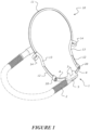
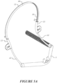
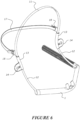
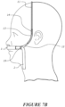
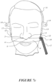
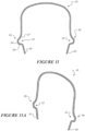
- Figure 1 shows a patient interface 1 and headgear 10 according to some embodiments described herein.
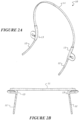
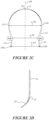
- Figures 3A to 3D illustrate a similar headgear attached to an alternative patient interface.
- the patient interface shown in Figures 3A to 3D is the same or similar to the interface described in US provisional application 62/399893 .
- the patient interface and/or headgear as described in this specification may be used in the respiratory system as disclosed in PCT Application no. WO 2016/157105 .
- a tube or conduit 2 provides a flow of respiratory gases to the patient via the interface 1.
- the patient interface comprises the tube 2.
- the patient interface is a nasal cannula comprising a pair of nasal prongs 3.
- the nasal prongs interface with the nares of a patient or user to provide a flow of respiratory gases to the user.
- the prongs provide a flow of gases to the user without forming a seal with the nares or nasal passages.
- the interface 1 may comprise a manifold section 5 comprising an inlet receiving gases from the tube 2 and an outlet or outlets, e.g. the prongs 3.
- the manifold 5 directs gases received by the manifold from the tube 2 to the prongs 3.
- the headgear may be attached to either side of the patient interface.
- the patient interface comprises a side member or arm 4 on each side of the interface.
- the illustrated example has a side arm 4 extending from each side of the manifold section 5.
- the headgear is attached to each side arm 4, e.g. to an end or end portion of each side arm.
- a conduit portion may be integrally formed in or with a side member or arm 4 of the cannula.
- a side member or arm 4 is a conduit for transporting a flow of gases from a patient conduit to the manifold section 5.
- the side arm conduit 4 may comprise a collapsible portion. Substantially a full length of the side arm conduit 4 may be configured to collapse, or a portion of the length of the side arm conduit may be configured to collapse.
- patient interface may be adapted to deliver a high flow therapy.
- 'High flow therapy' as used in this disclosure may refer to delivery of gases to a patient at a flow rate of greater than or equal to about 10 litres per minute (10 LPM).
- 'high flow therapy' may refer to the delivery of gases to a patient at a flow rate of between about 10 LPM and about 100 LPM, or between about 15 LPM and about 95 LPM, or between about 20 LPM and about 90 LPM, or between about 25 LPM and about 85 LPM, or between about 30 LPM and about 80 LPM, or between about 35 LPM and about 75 LPM, or between about 40 LPM and about 70 LPM, or between about 45 LPM and about 65 LPM, or between about 50 LPM and about 60 LPM.
- 'High flow therapy' may also for example, according to various embodiments and configurations described herein, be a flowrate of gases supplied or provided to an interface or via a system, such as through a flow path, but is not limited to, flows of at least about 5, 10, 20, 30, 40, 50, 60, 70, 80, 90, 100, 110, 120, 130, 140, 150 L/min (LPM), or more, and useful ranges may be selected between any of these values (for example, between about 40LPM to about 80LPM, or between about 50LPM to about 80LPM, or between about 60LPM to about 80LPM, or between about 70LPM to about 80LPM, or between about 5LPM and about 150LPM, or between 10LPM and about 150LPM, or between about 15LPM and about 150LPM, or between about 20LPM and about 150LPM, or between about 20LPM and about 120LPM, or between about 30LPM and about 120LPM, or between about 20LPM and about 100LPM,or between about 20LPM and about 90LP
- Gases delivered may comprise a percentage of oxygen.
- the percentage of oxygen in the gases delivered may be between about 20% and about 100%, or between about 30% and about 100%, or between about 40% and about 100%, or between about 50% and about 100%, or between about 60% and about 100%, or between about 70% and about 100%, or between about 80% and about 100%, or between about 90% and about 100%, or about 100%, or 100%.
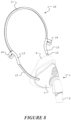
- the headgear 10 comprises at least one headgear member, for example a headband 11, and a pair of flexible joints 13 adapted to connect ends or end portions of a headgear member or a pair of headgear members to a patient interface.
- Each flexible joint 13 allows relative movement between the headgear member and the patient interface with at least two degrees of freedom.
- each flexible joint 13 allows free relative movement between the headgear member and the patient interface with at least two degrees of freedom.
- 'free movement' or to 'move freely' means the flexible joint does not employ a mechanism such as friction or mechanical indexing to impede movement or set or lock the flexible joint in a particular position.
- the flexible joint may allow free movement with at least 2 degrees of freedom between limits of movement. Limits of movement may be provided by the headgear members, for example by material choice and/or geometry.
- the headgear 10 comprises a plurality of headgear members 11, 12 connected together.
- the headgear may comprise a headband 11 and a pair of arms 12 attached to the headband.
- Each arm 12 may be adapted to connect to a patient interface 1.
- each arm 12 facilitates connection of the headgear 10 to the patient interface.
- the arms 12 act as a connecting structure between the interface 1 and the headband 11.
- the headband is a resilient headband.
- the arms 12 are resilient arms.
- Adjacent headgear members 11, 12 are attached or connected together by a flexible joint 13.
- the headgear members are integral with the flexible joint 13.
- the at least one headgear member is/are releasably attachable, or connectable and detachable or disconnectable, with or from an adjacent headgear member and/or the flexible joint.
- an end of the at least one headgear member extends past or beyond the flexible joint 13, which can increase contact with a user's head when in use for better pressure distribution
- the flexible joint 13 allows for one member (e.g. arm 12) to move freely relative to the adjacent connected member (e.g. the headband 13).
- the flexible joint 13 allows relative movement between adjacent headgear members with at least two degrees of freedom.
- the headband 11 is shown to move in a direction relative to the arms 12, that is a front-and-back direction, and the flexible joint may also allow each arm 12 to move relative to the headband in a left side to right side direction (i.e. perpendicular to the page), presenting two degrees of freedom of relative movement between the members 11, 12.
- the flexible joint 13 may be located at or near the sides of a user's heard, and/or at or near the top of a user's head.
- the flexible joint is located at or near a central portion of a headband.
- the flexible joint 13 allows relative movement between adjacent headgear members with at least one degrees of freedom.
- the flexible joint 13 may provide for elongation optionally in a lengthwise direction. The elongation of allows for movement between adjacent headgear members in a direction away from each other. Elongation of the flexible joint 13 can help to size the headgear for a particular patient.
- the flexible joint 13 may be provided by or comprise a substantially u-shaped portion.
- the flexible joint may have a first portion extending outward from a headgear member in use (e.g. outwardly from the user's head), and a second portion extending toward a headgear member in use (e.g. toward from the user's head).
- the flexible portion 13 may have an intermediate portion located intermediate the first portion and the second portion, the intermediate portion extending substantially parallel to a headgear member in use (e.g. parallel to the user's head).
- the flexible portion may be integrally formed as part of the headgear member, and/or headband.
- the flexible portion may be formed of the same material as the adjacent headgear members but be geometrically shaped to have a greater stiffness in one particular plane relative to one or more other planes.
- the flexible joint is stiffer in a coronal plane of the user, or a plane of the headband, as compared to the sagittal and medial planes of a user (or the other orthogonal planes).
- the flexible joint 13 may comprise a narrowed portion optionally to form a hinge.
- the narrowed portion may comprise one or more rounds, bevels or substantially V-shaped portions, to narrow the at least one headgear member from a first cross-sectional area to a second cross-sectional area which is smaller than the first cross-sectional area.
- the flexible joints may comprise a relatively flexible material relative to the headgear members (i.e. rubber or silicon) and/or a concertina or bellows section and/or a spring section so as to allow for relative movement by elongation of the flexible joint, and preferably at least some relative movement of connected headgear members away from each other.
- a relatively flexible material relative to the headgear members i.e. rubber or silicon
- a concertina or bellows section and/or a spring section so as to allow for relative movement by elongation of the flexible joint, and preferably at least some relative movement of connected headgear members away from each other.
- the flexible joint may allow for relative movement of around 5mm to around 20mm.
- the flexible joint may comprise at least one, or a plurality of sub sections.
- each sub section is a flexible joint as described elsewhere in the specification.
- one or more sub section(s) may provide for flexibility or free relative movement in one or more directions or degrees of freedom.
- the flexible joint may comprise one or more living hinges, where each living hinge provides for flexibility or free relative movement in a degree of freedom.
- one or more sub section(s) may provide for elongation (optionally lengthwise or in a direction along the at least one headgear member) to allow free relative movement between the headgear member or members and the patient interface or between the headgear member and adjacent headgear members.
- the flexible joint may comprise so one or more: living hinge, or concertina, or bellows section, or spring section.
- the flexible joint 13 is adapted to bend or fold laterally to a longitudinal axis of an end portion of a said headgear member, e.g. the headband 11.
- the joint may bend or fold/flex in any direction perpendicular to a longitudinal axis of an end portion of the headgear member (2-degrees of freedom).
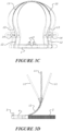
- the flexible joints 13 may allow the headband to be folded over onto the arms 12 to provide a folded up non-use configuration, for example in a package for sale.
- the flexible joint is or may comprise a flexible unitary member, for example a hollow member or a tubular member, e.g. a length of tube.
- the flexible joint may be a formed from a soft flexible material, such as an elastomeric material.
- the flexible joint may be a length of elastomeric tube, for example silicone tube or tubular member.
- the flexible joint preferably elastically deforms (without permanent deformation) under normal use conditions, so that the joint may flex between different positions many times without changing mechanical properties.
- the flexible joint may be over-moulded to the headband 11, or may be assembled to the headband.
- the flexible joint may be provided by a mechanical assembly or mechanism, for example a universal joint, or a two way hinged assembly allowing for hinging about two perpendicular axes.
- a hinge may be a living hinge.
- the flexible joint allows for rotation of a said headgear member, e.g. arm 12, relative to an adjacent headgear member, e.g. band 11, about a longitudinal axis of an end portion of the headgear member 12 attached to the adjacent headgear member 11.
- This rotation may be provided for by torsional elastic deformation of the flexible joint, e.g. twisting of the flexible joint.
- This torsional deflection presents a further freedom of movement, such that in some embodiments the flexible joint presents three degrees of freedom of movement.
- the flexible joint simultaneously accommodates lateral bending/folding in two degrees of freedom and also torsional rotation, to allow the joint 13 to flex in multiple dimensions.
- the flexible joints 13 take up or allow for torsional forces and bending resulting from movement of the arms 12 and/or interface 1 relative to the headband 11.
- the flexible joint provides bias against movement from an un-deflected or 'normal' position.
- the flexible joint is or comprises a flexible member such as an elastomeric member.
- the elastomeric member presents an un-deflected shape or relative position between adjacent members connected together by the flexible member. Movement between the connected members is achieved by flexing the flexible member away from the un-deflected position and resiliency of the flexible member acts to bias the flexible joint to the un-deflected position.
- a mechanical flexible joint may comprise a resilient member, e.g. a spring, to bias the joint to an un-deflected position.
- the flexible joint may comprise a bellows or concertina section.
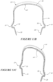
- the flexible joints 13 may be absent and the headband 11 may be a continuous rigid headband.
- the headband 11 may be a continuous rigid headband.
- Such arrangements are shown in Figures 11-11A and 13A-13C which show continuous headbands 11.
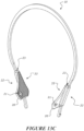
- these arrangements may comprise a single piece headband, a rigid or continuous headband with flexible joints 13 (for example as shown in Figures 11B and 11C ).
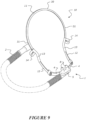
- the headgear comprises at least one connecting portion or connection arrangement 20.
- the connecting portion or connection arrangement 20 may be located on, or form part of the flexible joint(s) 13, or the at least one headgear member (for example band 11 or arm 12).
- the connecting portion or connection arrangement 20 may be configured to provide for connection with one or more of: an interface (for example interface 1, or any of the interfaces as shown in Figures 1 , 3A-13C ), or a part of an interface, an arm (for example side arm 4) adapted to connect to or form part of an interface.
- the connecting arrangement 20 when the connecting arrangement 20 is located on the at least one headgear members, the connecting arrangement 20 may be located away from an end of the at least one headgear member so that the headgear member extends past the connecting arrangement 20 to optionally rests on the user's face.
- the connecting portion or connection arrangement 20 may be configured to provide for a pivotal connection, or a rigid or semi-rigid connection.
- the connecting portion or connection arrangement 20 may comprise a recess, or aperture 21 configured to receive a projection or boss 21a, optionally the projection or boss 21a may be located on an interface 1 or part of an interface, optionally the recess or aperture is located on, or as part of, the flexible joint 13, or on a sliding member 22 of the headgear 10.
- the projection or boss may comprise a first portion 35 which has a smaller diameter or cross-sectional area than a second portion 36.
- the second potion 36 may be configured to retain the projection or boss 21 within recess or aperture 21.
- the connecting portion or connection arrangement 20 comprises a projection or boss configured to be received by a recess or aperture.
- the projection or boss 21a is located on the flexible joint 13 or on a sliding member 22 of the headgear 10, optionally the recess or aperture is located on an interface or part of an interface.
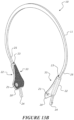
- the connecting portion or connection arrangement 20 may comprise of a slot 37 and a projection 38.
- the slot 37 or projection 38 may be located on, or form part of the flexible joint(s) 13, or the at least one headgear member (for example band 11 or arm 12) with the remaining part (i.e. the projection 38 or slot 37) may be located on one or more of: an interface (for example interface 1, or any of the interfaces as shown in Figures 1 , 3A-13C ), or a part of an interface, an arm (for example side arm 4) adapted to connect to or form part of an interface.
- Such a connection arrangement 20 is shown in Figures 14C and 14D .
- the slot 37 and projection 28 may be connected by one or more connection features, or any adhesive, or alternatively by over moulding.
- connection portion or connecting arrangement 20 may be one or more of: a Snap-fit, lock/key arrangement, male/female connection, or a plug socket arrangement.
- the arm of the interface, the flexible joint, and/or the sliding member of headgear may comprise one or more corresponding connection portions or arrangements.
- multiple corresponding connection portions or arrangements may be provide on the arm of the interface, the flexible joint, and/or the sliding member of headgear to provide for various sizings, for example adjustments along the height, e.g. a distance from the tip of the chin to the level of the top of a user's head, and/or depth, e.g. anterior to posterior of a user's head.
- connecting portions 20 are not shown however an example of a location of the connecting portions 20 is shown. It will be appreciated that these embodiments could be modified to include the connecting portions 20 as described above.
- the headgear and an interface, or a part of an interface, or an arm adapted to connect to or form part of an interface may be integrally formed.
- a headgear member 11, 12 may be moveably attached to the flexible joint to move relative to an adjacent headgear member along a longitudinal axis of an end portion of the headgear member 11, 12 attached to the flexible joint.
- the headgear member is telescopically attached to the flexible joint.
- One or both arms 12 may be movably attached to the respective flexible joint 13 to allow the arm 12 to move along a longitudinal axis of the end portion of the arm attached to the flexible joint.
- the arm or member may be received within a bore or recess of the flexible joint to slide therein to form a telescoping engagement.
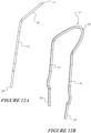
- FIGS 13A-13C show a sliding member 22 being configured to slide relative to the headgear member (for example headband 11, or end 12a of resilient arm 12.)
- the sliding member 22 is or optionally comprises flexible joint (as described above.)
- the sliding member 22 may comprise at least one passageway 23.
- sliding member 22 is or comprises a hollow or tubular member, which may optionally form said passageway 23.
- the at least one passageway 23 may be configured to allow for the passage of the headgear member.
- the headgear member may be configured to move or slide relative to the sliding member 22.
- an end of the at least one headgear member extends past or beyond the sliding member 22. In some embodiments the end of the at least one headgear member may be configured to rest on a part of the patients head or face in use.
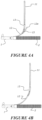
- the flexible joint may include an opening or openings, each opening (15 in Figure 4A but obscured from view) allowing an end of the headband 11 or end 12a of resilient arm 12 to extend through a side of the flexible joint.
- the relative position of the headgear members may be adjusted by pushing the headgear member through an opening to position the flexible joint a desired longitudinal position along the headgear member, or by positioning the arm within the flexible joint, as shown in Figure 4B .
- Relative movement between the headgear member and the flexible joint allows for size adjustment of the headgear to accommodate different sized users. Size adjustment can be in an anterior direction and/or can also be in the superior or vertical direction.
- the headgear member may comprise at least one stop 24, 25 to limit movement of the headgear member relative to the sliding member 22 and/or the at least one passageway 23.
- the at least one stop may be located at or near an end of the headgear member (for example stop 24), and/or along a length of the headgear member (for example stop 25).
- the at least one stop may comprise one or more of:
- headgear member (for example headband 11) comprises at one or more of: a first stop 24, and a second stop 25.
- the first stop 24 may provide for a first limit of movement of the head gear member relative to the sliding member 22 (which may optionally be a flexible joint) and/or the at least one passageway 23.
- the second stop 25 may provide for a second limit of movement of the head gear member relative to the sliding member 22 (which may optionally be a flexible joint).
- the flexible joint may allow for relative movement (optionally by elongation of the flexible joint) of around or about 5mm to around or about 20mm.
- each flexible joint provides for stepped telescopic movement in increments of about 5mm, for example via engagement and disengagement of notches in, along and/or on the passageway 23.
- the sliding member 22 comprises a connecting portion 20 as described elsewhere in the specification.
- the connecting portion 20 may be located to one side of the sliding member 22, optionally, the connecting portion 20 is located distally from a centre of the sliding member 22, or the passageway 23.
- the connecting portion 20 may be located on a side of the sliding member 22 opposite the patient's face. In some embodiments the connecting portion is located in a lower portion of the sliding member.
- the headgear may be provided with an interface, and the headgear and interface may be configurable between a storage configuration, and an in use configuration.
- the interface may pivot about the headgear via connection portion 20 so the headgear is folded towards the headband 11. This provides for a storage configuration with a smaller profile.
- the interface may pivot and/or hinge about the headgear via flexible joint 13 so the headgear is folded towards the headband 11.
- the headband 11 and interface may be folded towards a common plane, so that in a storage configuration the interface and headgear may be folded in a common plane.
- the in use position may be that shown in any of Figures 1-10 where the interface is disposed at an angle from the headgear.
- the sliding member 22 may comprise an engagement portion 33 as described below.
- the sliding member 22 may have at least one engagement portion.
- each of a, or the, pair of sliding members 22 each have an engagement portion 33.
- the sliding member may be made of a stiffer material than the at least one headgear member, and/or the headband. In some embodiments the sliding member may be made of a more flexible material than the at least one headgear member, and/or the headband.
- the sliding member may be configured to deform the profile of the headgear member which passes through the passageway to provide for a predetermined profile of a section of the headgear member in the area which passes through the passageway.
- this section is a straight section, or a curved section.
- the longitudinal movement may be indexed or otherwise settable to set the longitudinal position of the headgear member to the flexible joint.
- the longitudinal position may be set so that the member substantially does not move freely relative to the flexible joint.
- the headgear member may comprise protrusions or depressions (e.g. dimples or grooves) to be received by corresponding depressions or protrusions of the flexible joint, to provide an indexing arrangement to set the longitudinal position of the member to the flexible joint.
- protrusions or depressions e.g. dimples or grooves
- the headband and/or arms may be marked with size graduations, which may align with a corresponding indication or other feature on the flexible joint.
- the each one of the pair of flexible joints engages a respective side of the user's head in use.
- the headband is shaped to fit over the top of a user's head with each end of the headband located to a respective side of the user's head.
- the headband 11 is a resilient headband shaped to fit a user's head with each end of the headband located to a respective side of the user's head, and each flexible joint is attached to a respective end or end portion of the headband.
- the pair of flexible joints 13 provide or comprise a pair of engagement portions 33, each engagement portion 33 configured to engage a side of the user's head in use.
- the flexible joints may be adapted to attach directly to a patient interface, or may connect adjacent headgear members together, like members 11 and 12 shown in Figure 1 .
- the arms 12 are removably coupled to the interface 1.
- the arms 12 directly couple to the side arms 4 of the interface 1, e.g. to ends of the arms 4.
- Each arm 12 couples to one lateral end of the interface and the lateral ends are laterally opposed to each other.
- one or both arms 12 may be a resilient arm.
- the headband is shaped to fit over the top of a user's head. In some embodiments, the headband is shaped so that the flexible joints connecting the arms to the headband are located in use:
- headband 11 comprises a central portion 30 and an end portion(s) 31.
- the end portion(s) may be located to a side or a respective side of the user's head.
- the central portion 30 may be angled with respect to the end portion(s), optionally, to fit about a rear portion of the user's head in use.
- the central portion 30 adapted to fit about a rear portion of a user's head in use, allows the headband to fit a wide range of user head sizes.
- the headband is a resilient band, e.g. a headband formed from a resilient material.
- One or both arms may be resilient arms, and may be formed from the same resilient material as material of the headband.
- the resilient headband is shaped to fit a user's head with each end of the headband located to and biased against a respective side of the user's head.
- the distance between the ends of the headband is less than a width of a user's head so that deflection of the headband to fit the user's head biases the ends of the headband against sides of the user's head in use.
- the headband is of a sufficient length relative to its cross section to be flexible enough to allow a user to spread apart ends of the headband by a user and to provide a comfortable amount of force against the sides of a user's head.
- the amount of bias provided by the headband provides a force to the user's head that is comfortable yet assists to maintain a correct position on the user's head.
- the geometry, e.g. the length and cross sectional area, of the arms 12 may prevent significant flexing of the arm in normal use.
- the arm 12 may be sufficiently short relative to its cross sectional area to resist bending laterally or twisting.
- the arms 12 although may be made from the same material as the resilient headband 11, are rigid (e.g. do not flex substantially under normal use conditions).
- arms 12 are rigid when the interface is substantially soft and flexible like in the embodiments of Figure 3A - 6 .
- Rigid arms 12 assist in maintaining a robust connection between headband 11 and the interface 1, and arms 12 function to effectively transfer forces from the interface 1 to the flexible joints 13.
- a central portion 30 of the headband 11 is relatively stiffer or more stiff or less flexible, than the end portions 31.
- the central portion 30 may have a larger cross-sectional area than the end portions 31.
- the central portion 30 may have a cross-sectional area different than the end portions 31.
- the central portion 30 is made of a first material and the end portions 31 are made of a second material, and the first material is relatively stiffer or more stiff or less flexible, than the second material.
- the relative stiffness of the central portion 30 to the end portions 31 may be provided a particular direction for example in a direction towards a user.
- the resilient headband and/or resilient arms may have a rectangular cross section, a trapezoidal cross section, a circular cross section, or any other suitably shaped cross section.
- a cross section with a flat surface is adopted to provide sufficient contact area on the user's head so that sufficient friction is present to retain the headband in a desired position.
- the flat face will sit against the head and/or face of the user.
- the cross section of the headband and/or arms may change along their lengths, for example widening, or narrowing in order to provide greater or lesser dispersion of forces about regions of the patient's face and/or head.
- the modulus of elasticity (Young's modulus) of at least one of the headgear members is at least about 0.5GPa, or at least about 1GPa or at least about 1.5GPa, or at least about 1.8GPa, or at least about 2GPa, or at least about 3GPa.
- the headband or the headgear and arms may be formed from polymers which include but are not limited to rubbers (natural and synthetic) and plastics such as acrylonitrile butadiene styrene (ABS), polyethylene terephthalate glycol (PETG) and polypropylene (PP) which has a modulus of elasticity of about 1GPa to 3GPa.
- the headband or headband and arms may be formed from a metal material, for example a high tensile steel.
- the Young's modulus of the headgear members may be 200GPa or even higher.
- the headband or the headgear and arms may be formed from a resilient material which is not substantially brittle.
- one or more of the headgear members may comprises a plastic core and a textile casing, wherein the plastic core and the textile casing are formed as an integral structure by the application of a molten plastic material into the textile or natural fibre casing or a composite of textiles and natural fibres, for example as described in PCT application published as WO2016/043603 .
- the textile may be a synthetic textile or a textile made from natural fibres. Examples of natural fibres include wool, jute and flax.
- the plastic core of the headgear member may provide a resiliency so that the member is a resilient member. Additionally or alternatively a resilient member such as a metal band may be provided in or together with the plastic core to provide sufficient resiliency.
- the flexible joint may be formed from a resilient material with a significantly lower modulus of elasticity.
- the flexible joint may be formed from a material with a modulus of elasticity of less than about 0.2GPa, or less than about 0.1GPa, or less than about 0.06GPa.
- An example material is silicone rubber, which may have a Young's modulus of 0.05GPa or less.
- the headgear members are formed from a relatively stiff resilient material and the flexible joint is formed from a correspondingly relatively soft flexible material, wherein the modulus of elasticity of the stiff resilient material is many times greater than the modulus of elasticity of the soft flexible material.
- the soft flexible material is resilient in that it deforms without plastic deformation under normal use conditions. However, it is much more flexible than the material of the headgear members.
- the modulus of elasticity of the stiff resilient material of the headgear members is at least 10 times the modulus of elasticity of the soft flexible material of the flexible joints, or at least 20, or 40, or 100, or 200 times the modulus of elasticity of the soft flexible material.
- the flexible joints 13 isolates or separates movement of the interface from the headband, so that the headband is less likely to be disturbed on the head of the user.
- the headgear is mostly held to the user's head by the headband.
- the flexible joints 13 may act to isolate the lower portion of the headgear and/or interface to avoid or reduce disturbance of the bias toward the sides of the user's head provided by the headband.
- At least one positioning tab 14 or positioning member 26 is connected to, or forms part of, at least one said headgear member.
- the headgear has a pair of positioning tabs 14 or positioning members 26, each tab or member located at or near to an end or end portion of the headband 11.
- the at least one positioning tab or positioning member may allow a user to apply and remove said headgear.
- the tabs or members are arranged to be located at a side of the user's head in use.
- the positioning tab or positioning member 26 is provided on one of the flexible joints 13 described earlier.
- the tab 14 or member 26 may be integrally formed with the flexible joint.
- the least one positioning tab 14 or positioning member 26 is connected to, or integrally formed with a headgear member.
- the flexible joint with tab 14 or member 26 may be a unitary member.
- the tabs 14 or members 26 are provided with indicia to illustrate a direction to pull the tab to remove the headgear from a user's head, for example the tabs or members may include arrows marked on or formed in the tabs, as illustrated in the figures, the arrow indicating the direction to pull the headgear for removal.
- the tabs or members may extend from the headgear member so that in use the tabs protrude or extend outwardly from the user's head.
- the at least one positioning tab 14 or positioning member 26 may be provided by a substantially U-shaped portion.
- the positioning tab 14 or positioning member 26 comprise a first portion 27 extending outward from a headgear member in use (e.g. outwardly from the user's head), and a second portion 28 extending toward a headgear member in use (e.g. toward from the user's head).
- the positioning tab 14 or positioning member 26 comprise an intermediate portion 29 located intermediate the first portion 27 and the second portion 28, the intermediate portion 29 may extend substantially parallel to a headgear member in use (e.g. parallel to the user's head).
- the geometry of the positioning member can provide for the channel 32 as described below.
- Figure 3C illustrates deflection of the headgear 10 and patient interface 1 in a direction lateral to the sagittal plane of a user.
- a user or medical practitioner may pull on the tabs, e.g. by gripping the tabs between thumb and forefinger, to apply and remove the headgear.
- the medical practitioner may use the tabs to reposition the headband, for example by adjusting an angle of the headband relative to the arms 12 to better support or position the patient interface and/or improve patient comfort.
- the headband 11 may comprise one or more flexible joints 13.
- Figures 11B and 11C illustrate deflection of the headgear 10 in a direction along the coronal plane (i.e. perpendicular to the sagittal plane of a user).
- Figures 11B and 11C illustrate deflection of the headgear 10 in a direction from the chin towards the forehead of a patient, or from the forehead towards the chin of the patient.
- the solid line section 10" shows the original un-deformed shape of the headgear 10.
- the dashed line section 10' shows the deformed shape of the headgear when the headgear is stretched in a substantially coronal plane (for example when it is placed on or fitted to a user).
- the interface can be fitted to a user by stretching the flexible joint 13 to allow for the headgear to be deformed to match the shape of the head of a user. Once the stretching force is removed the headgear may return towards its un-deformed shape 10" to engage with a head of a user.
- the shape of the headgear when a force is applied to the headgear to fit the headgear and/or interface to a user's head, the shape of the headgear changes from a generally tall oval to a rounded rectangle shape.
- positioning tabs 32 may be provided as part of the, or separately to, the flexible portion 32 these may assist a user to fit the headgear as is described elsewhere in this specification.
- the user may pull on or twist the tabs or members to apply a torsional force to the headgear members to twist the headgear member so as to open the headgear (e.g. in a direction along the sagittal plane of a user's head in use) so it can be applied or removed from a user's head.
- the headgear members and/or the flexible joints may be configured to deform torsionally when a force is applied to the tabs or members. Applying a force (e.g. pulling) on the tabs or members may elastically deform the headgear (for example one or more of a flexible joint, a headband, an arm, or any other headgear member).
- the headgear may return towards an initial resting state whereby it engages with the head of a user.
- there may be no flexible joint e.g. in Figures 11, 11A , 12 and 12A where the headband 11 could be configured to connect directly to a patient interface
- the flexible joint may be configured to deform torsionally.
- the headband may be made from a material such as PETG (Polyethylene Terephthalate with a glycol modification).
- PETG Polyethylene Terephthalate with a glycol modification
- the headgear comprises a pair of engagement portions 33, each engagement portion 33 configured to engage a side of the user's head in use.
- each engagement portion 33 frictionally engages a side of the user's head.
- One or more engagement portions 33 may be integral with the headgear, or part thereof, and/or the at least one flexible joint, and/or be removable separate portions.
- the engagement portions 33 may provide friction pads to engage the user's head, and improve contact with the user's face.
- the engagement portion 33 comprises a textured surface to contact the head of the user, to increase friction between the headgear and a user's head to assist with maintaining the headgear in position on the user's head.
- the textured surface may comprise one or more of: a knurled portion, a waved surface, a ribbed surface, a roughened surface, or may comprise micro or nano projections.
- the engagement portion may 33 comprise an adhesive for engagement with the head of the user.
- the adhesive may be a biocompatible adhesive.
- the headgear may comprise a removable cover over the adhesive to be removed before user, e.g. a peelable layer.
- the pair of flexible joints 13 is or comprises the pair of engagement portions 33, each one of the pair of flexible joints configured to engage a side of the user's head in use.
- a textured pad or surface may be provide on an inwardly facing surface of the flexible joint to engage the side of the user's head.
- the headgear members 11, 12 are connected together to form a continuous loop together with the patient interface in use.
- the continuous loop is formed by the manifold section 5, interface side arm 4, headgear arm 12, flexible joint 13, headband 11, flexible joint 13, headgear arm 12 and interface side arm 4.
- the continuous loop comprises an upper portion and a lower portion with ends of the upper portion and ends of the lower portion connected together by the pair of flexible joints 13.
- the upper portion is provided by the headband 11, and the lower portion by the headgear arms 12 and patient interface 1.
- the arms and headband may be moveably attached together for relative movement therebetween along a longitudinal axis of the end portion of the arm.
- at least one end portion of the lower portion may be moveably attached to an end of the upper portion for relative movement therebetween along a longitudinal axis of the end portion of the lower portion. This movement allows for the length of the loop to be adjusted to correspond with a user's head size.
- the end portion of the lower portion is telescopically attached to an end of the upper portion, in a telescoping arrangement, for example as described earlier.
- the position tabs are preferably attached to the upper portion, e.g. to an upper portion side of the flexible joints.
- At least one positioning tab is connected to at least one of the upper portion and the lower portion.
- the headgear members which are connected together to form a continuous loop may be connectable or disconnectable from each other so as to provide for locations where the continuous loop may be opened. This may be useful when the headgear needs to be removed from a user without disturbing other devices which may be attached to the user.
- the continuous loop may be connectable and disconnectable between the headgear member and the interface (i.e., by connection arrangement 20), and/or between adjacent headgear members. If the headgear is telescoping as described above the sliding member 22 may be disconnectable from the headband 11 to break the continuous loop.
- the headgear may comprises a channel 32 to allow for the passage of devices, or accessories (e.g. arms of a spectacle) from one side of the headgear to the other.
- the channel 32 may be located or form part of one or more of: the flexible joint 13, or the positioning tab 14 or positioning member 26, or the at least one headgear members, or the engagement portion 33.
- the channel may form a channel passageway between a surface of the flexible joint, or the at least one headgear members, or the at least one positioning tab, or positioning member, or the engagement portion 33 and a patient's head.
- the channel 32 may extend from a front side of the headgear to a rear side of the headgear.
- the channel 32 may extend from a front side of the flexible joint 13, or the positioning tab 14 or positioning member 26, or the at least one headgear members, or the engagement portion 33 to a rear side of the flexible joint 13, or the positioning tab 14 or positioning member 26, or the at least one headgear members, or the engagement portion 33.
- the channel may be provided by a substantially U-shaped portion.
- the headgear may comprise engagement portions located on one or both sides of the channel 32 to rest on the users face in use.
- the channel may be provided as part of the engagement portions 33.
- the headband 11 is curved and predominantly lies in a plane, and the arms 12 each extend predominantly in a plane that is transverse to the plane of the headband.
- each arm is curved to predominantly lie in a plane that is transverse to the plane of the headband.
- the flexible joints may provide for each arm to lie in a plane that is transverse to the plane of the headband, and/or the arms 12 may be curved predominantly lie in a plane that is transverse to the plane of the headband.
- the headgear when the headgear is in use, e.g. positioned on a user's head to hold the interface 1 in place, and when viewed from a front (e.g. looking at the patient's face), the headgear forms a loop together with the interface 1, and wherein the loop has a narrow portion 21 between a top 11c of the headgear 10 and a bottom 12a, 12b of the headgear.
- the headgear 10 has a first lateral distance 21 between portions of the headgear that engage the user's head (e.g. the flexible joints 13 may contact the head and therefore provide or form engagement portions), a second lateral distance 22 between left and right side portions 11a, 11b of the headband 11 intermediate the engagement portions 13 and a sagittal plane position 11c of the headband, and a third lateral distance 23 between ends or end portions 12a, 12b of the headgear attached to or attachable to the patient interface 1.
- a lateral distance is across and perpendicular to the sagittal plane.
- the sagittal plane is identified by reference numeral 24.
- the first lateral distance 21 is less than the second 22 and third 23 lateral distances. In some embodiments, the second lateral distance 22 is greater than the third lateral distance 23.
- the user's head is clamped between the engagement portions located at the smallest lateral distance of the headgear. The engagement portions are biased against the user's head by the headband 11, as described earlier.
- this arrangement provides for a contact with the user's head at the engagement portions.
- a portion of the headgear between the engagement portions and the interface 1 may not contact or may have minimal contact with the head or face of the user.
- the arms 12 may not bear against the user's face, or may make minimal contact with the user's face.
- the arms 12 may support side portions of the interface 1, e.g. side arms 4, away from the user's face, or support the interface or to make minimal contact with the user's face.
- arm 12 of the headgear may be resilient, i.e. formed from a resilient material.
- the arms may be stiff to resist significant bending under normal operating conditions.
- the arms may be curved in a side view, with at least one centre of curvature forward of the side arm, for example as shown in Figures 2D and 3D .
- the curvature of the arms 12 provides for a correct positioning of the patient interface 1 on the face of the user and/or may assist to reduce contact between the interface and the user's face. Correct positioning of the interface may also be provided by flexible joints described above.
- the headgear may comprise a pair of flexible joints to attach the headgear to the patient interface, or the patient interface may comprise a pair of flexible joints to connect to the headgear.
- the arms 12 may be connected to the patient interface by the pair of flexible joints.
- the flexible joints connecting the headgear to the interface may be as described earlier.
- the arms 12 may be integrally formed with or are part of the patient interface, and the headband 11 may be connected via the flexible joints 13 to the patient interface side arms.
- one or both arms 12 may be integrally formed with a part of the patient interface, for example the 'plug' 708 and the 'conduit connector' 707 of the interface described in US provisional application 62/399893 , as shown in Figures 3A and 3B of this present application.
- the arms 12 may be integrally formed with the headband in a single continuous member.
- the headgear may comprise two pairs of flexible joints 13, one pair connecting between the headband 11 and the arms 12, and one pair connecting between the arms 12 and the patient interface 1.
- one or each arm 12 may be attached to the patient interface by ball and socket joint.
- the arms may be resilient.
- the arms 12 may be formed from soft flexible material.
- the arms 12 may be integrally formed with the flexible joints 13.
- An integrally formed flexible joint and arm member may comprise a flexible section forming the flexible joint, e.g. provided by a hollow section, and a less flexible or more rigid section forming the arm 12, e.g. provided by a solid cross section.
- the cannula or interface can be made of flexible material so that the side arms 4 of the cannula or interface can flex relative to the prongs. This flexibility provides additional adjustability of the headgear relative to the prongs since the cannula or interface side arms can move relative to the prongs.
- the resilient headband 11, flexible joints 13 and/or resilient arms 12 may be or comprise conduits.
- a resilient headband conduit may simultaneously secure the headgear to the patient's face and head while also providing a flow path to supply the patient interface with incoming gases.
- Conduits of the arm 12, flexible joint 13 and headband may connected together to be in fluid communication.
- an end of the arm and an end of the headband may be received in the flexible joint.
- a second headband 16 may additionally be provided to enhance securement to the patient's head.
- the second headband 16 may be engageable with a rear part of a user's head, and optionally the second headband may engage with a portion of the user's head rearward of a crown of a user's head.
- the second headband 16 may be resilient, flexible with a reduced modulus of elasticity compared to the headband 11, or may be an elasticated strap or an elastic cord.
- the second headband may be an elastic strap or band.
- the elastic strap or band may be elastic, and/or stretchable and/or elongatable.
- the second headband may be detachable from the remaining headgear components.
- the second headband may attach or releasably attach to the resilient headband 11 or to the flexible joints 13.
- the flexible joints 13 may have a 'Y' shape to accommodate both the first headband 11 and the second headband 16.
- the headband 11 may comprise a groove or cavity to store the second headband when the second headband is not required during use.
- the groove or cavity may be a scallop, or valley and may be C-shaped.
- the second headband for example an elastic cord is retained in the groove or channel in an outer surface of the resilient headband 11, as presented in Figure 5A .
- the second headband may be removed from the groove or channel for use, as shown in Figure 5B .
- the second headband 16 may alternatively be retained by retention clips provided on the resilient headband 11.
- the second headband 16 may be optionally provided to the headgear.
- the second headband may be optionally secured to the headband or arms or flexible joints by a connection feature to allow the second headband to be connected to the headband.
- a connection feature may comprise clips, connectors, grooves, or buckles for example.
- Figure 6 illustrates a second headband 17 which is an elastic band which is optionally attachable to the headgear by connectors 18.
- the strap may be provided with a connector half and the first headband, flexible joint or arm may be provided with a corresponding connector half.
- Figures 7A to 7C illustrate a headgear together with an interface that is similar to the headgear and interface shown in Figures 3A to 3D .
- the arms 12 of the headgear comprise a larger vertical dimension relative to the arms 12 of the embodiment shown in Figures 3A to 3D .
- the arms may contact the user's face, as shown in Figure 7C , to assist with supporting and maintaining a correct position of the interface on the user's face.
- the headgear may have a band or other feature 19 to secure a breathing conduit to the arm 12.
- FIGS 11-11A illustrate a headgear connectable with an interface.
- the headgear 10 may comprise a headband comprising positioning members 26.
- the positioning members 26 may act as flexible joints 13.
- the positioning members 26 may be used to fit the headgear to a user by a user pulling or applying force to the positioning members 26. This allows for extension of the profile of the headgear in a coronal plane of a user.
- the embodiment of Figures 11-11A also includes a channel 32 providing for a channel pathway between the user and the headgear 10.
- FIGS 13A-13C illustrate various headgears connectable with an interface.
- the headgear 10 comprises a pair of sliding members 22 which are configured to telescopically slide relative to the headgear member 11.
- the sliding members 22 comprise a connection arrangement 20 for connecting the headgear to an associated interface.
- the sliding members 22 of Figures 13A may have a flexible joint 34 to allow for movement between the sliding member 22 and the connecting arrangement 20.
- the flexible joint 34 may be a more flexible material than the remaining sliding member and/or connection arrangement, for example the flexible joint 34 may be made of a more flexible material (relative to the sliding member 22 and/or connection arrangement 20) and/or have a localised decrease in cross-sectional area (relative to the sliding member 22 and/or connection arrangement 20).
- the flexible joint 34 may be a living hinge.
- the sliding members 22 comprise positioning tabs or positioning members as described elsewhere in the present specification.
- a headgear according to described embodiments may be used together with other types of patient interfaces.
- a headgear according to embodiments described herein is shown together with a full face mask that covers the user's mouth and nose.
- the face mask comprises a seal 6 for contacting a user's face, and a body 7.
- the side arms 12 of the headgear may be connected to the body 7, by connectors, or may be formed with the body.
- Figure 9 shows a headgear according to embodiments described herein together with a patient interface comprising nasal pillows to engage the nares of a user.
- a patient interface comprising nasal pillows to engage the nares of a user.
- Other under-nose interfaces may be used, for example interfaces that seal against or over a base of the user's nose.
- Figure 10 shows a headgear according to embodiments described herein together with a nasal interface.
- the nasal interface comprises a body 7 and a nasal seal 6 for sealing over the user's nose.
- the headgear may also be provided as part of an assembly with a patient interface (for example as described above).
- the patient interface may be a nasal cannula, a full face mask, a nasal pillow mask, a nasal mask, an endotracheal tube, or a breath collector/sampler for sampling gases.
- the interface may be a sealing or a non-sealing interface.
- a method for donning a headgear to a user's head.
- the method comprises applying a lateral force to each side or end of a resilient headband 11 against the inwards bias provided by the resilient headband to deform ends of the headband outwards.
- the method then comprises positioning the headband over the top of a user's head, and releasing the lateral force from each side or end of the resilient headband so that the bias of the headband forces engagement portions (e.g. flexible joints 13) of the headgear against sides of the user's head to hold the headgear to the user's head.
- the relative position between the headband and the patient interface is adjusted by flexing the flexible joints 13 for correct placement of the patient interface on user's nose, mouth or nose and mouth.
- the headband may be positioned over the top of a user's head, and/or the engagement portions may be located:
- the method in the method of donning the headgear, includes gripping and pulling the pair of positioning tabs 14 to apply the lateral force to each side or end of a resilient headband of the headgear against the bias provided by the resilient headband to deform ends of the headband outwards. The outward force is then released to position the band correctly in place.
- the method may further comprise adjusting the position of the headband 11 or arm 12 to the flexible joint 13 for correct placement of the patient interface on user's nose, mouth or nose and mouth.
- the method may further comprise applying the headband 11 to the head of the user and without applying a secondary headband or strap around the back of the user's head.
- the headband may be applied to the user's head with the user's head resting on a support (such as a pillow) and without lifting the user's head from the support, and/or the headband may be applied to the user's head without moving the user's head.
- Embodiments described herein may allow for rapid application and removal of the patient interface without disturbing the patient's hairnet or the position of the patient's head.
- the headgear configuration may disperse weight of the interface and tube 2 over the top of the user's head.
- the medical professional may adjust the angle of the headband relative to the arms 12 to an optimal position to best disperse the weight of the patient interface and the tubing.
- the headband may be tilted forward or backward to provide additional resistance to forces pulling away from the face.
- Some embodiments may provide for a large range of head sizes, for example by variation in fit provided by the flexible joints 13 and/or adjustment in longitudinal position between headgear members.
- a further advantage is that the patient interface is held in a stable position on the patient's face, due to being resiliently supported from each side of the user's head.
Description
- The present disclosure generally relates to a headgear for a patient interface such as a face mask, nasal mask or nasal cannula.
- Patients may lose respiratory function during anaesthesia, or sedation, or more generally during medical procedures. Prior to a medical procedure a patient may be pre-oxygenated by a medical professional to provide a reservoir of oxygen saturation, and this pre-oxygenation and CO2 flushing/washout may be carried out with a high flow therapy via a nasal cannula or other patient interface.
- A patient interface may be held in place on a patient's face by a headgear. The headgear has head straps to extend around the head of a patient or user, to position and hold the patient interface in the correct position to provide respiratory gases to the patient. During fitting or removal of a nasal cannula or patient interface from the conscious or sedated patient it may be necessary for the medical professional to manipulate the position of the patient's head in order to apply or remove a head strap, or the like. As a result, this may cause some disturbance to the patient's position and/or comfort, provide awkward or uncomfortable mechanical loading on the medical professional, disturb the patient's hairnet and/or increase the time of the medical procedure.
- Additionally, elastic and/or size-adjustable head straps may present disadvantages. It may be difficult for the medical professional to grip or adjust a head strap - particularly with gloved hands. When attempting to grip an elastic head strap the medical professional may attempt to slide a finger between the head strap and patient's head, or try to pull the head strap away from the patient's head by pinching the head strap, or drag a head strap across a patient's hair and skin. As a result, the medical professional may inadvertently dislodge the patient's hairnet or pull the patient's hair or skin, or cause discomfort.
- In this specification where reference has been made to patent specifications, other external documents, or other sources of information, this is generally for the purpose of providing a context for discussing the features of the invention. Unless specifically stated otherwise, reference to such external documents is not to be construed as an admission that such documents, or such sources of information, in any jurisdiction, are prior art, or form part of the common general knowledge in the art.
-
WO2011/121466 describes a patient interface device that includes a mask and a headgear component for attaching the patient interface device to the head of a patient. The headgear component includes a strap and an attachment element provided between the mask and the strap. The attachment element has a mask attachment portion coupled to the mask, a strap attachment portion coupled to the strap, and a flexible linkage portion provided between the mask attachment portion and the strap attachment portion. The flexible linkage portion is more flexible than both the mask attachment portion and the strap attachment portion to enable the mask attachment element to flex, bend, and/or twist along multiple axes to conform to particular facial contours of the patient. -
WO2014/020469 describes a patient interface assembly and a force limiter. The force limiter is adapted to limit a force between a patient interface and a patient's face when the patient interface is applied to the patient. For this purpose, the force limiter comprises a spring-like element with a substantially degressive spring characteristic.WO2014/020469 further describes to a patient interface, an attachment assembly and a clip for use in a patient interface assembly and comprising said force limiter. -
WO2007/045023 describes a nasal mask assembly including a relatively flexible cushion arrangement including a cushion that provides a breathing chamber and a face-contacting portion to form a seal around the patient's nose in use, an inlet tube supported by the cushion to deliver breathable gas into the breathing chamber for breathing by the patient, and three support members extending outwardly from the cushion. A relatively rigid frame is provided to a front side of the cushion arrangement. The frame includes three headgear attachment structures. Headgear includes three headgear straps engagable with the three support members and the three headgear attachment structures to maintain the cushion arrangement in a desired position on the patient's face. -
EP1658873 describes a mask fastening unit with a head strap arrangement with connecting sections to be fixed to the mask body. The adapter is secured to the mask body at least temporarily. The connecting sections of the head straps are fixed to it. The adapter plate is constructed for location at the highest point of the mask body. It has a triangular shape. The adapter is metal, especially light alloy, or plastic. Silicon rubber or other highly flexible straps are used -
WO 2008/037031 describes a mask for supplying gas under pressure to an airway of a human including: a flexible manifold shell, being made of a flexible material, the manifold including means for connection to a gas delivery pipe. There are at least two side walls which are at least partially formed by portions of the manifold shell; a flexible face contacting element defining an orifice to accommodate the nose of the human; a first connecting strap having a first end connected to the mask and a second end connectable to a mask retaining strap; and a second connecting strap having a first end connected to the mask and a second end connectable to the mask retaining strap. The first strap and the second strap engage respective side walls of the mask for distributing opposing distortional forces to a substantial portion of the respective side walls when the mask is in use. The connection of the straps to the mask allow forces exerted by the first and second straps are capable of deforming the manifold at least along X and Y axes to create a variety of different mask/orifice shapes. The manifold of the mask has a manifold height and a centroid. The first and second straps engage the mask along a connecting length thereby joining the first and second straps to respective side walls of the mask so that an axis through the centroid normal to the Y axis, intersects with at least part of each strap. -
US2012/227744 describes a patient interface assembly that includes a patient interface device and a headgear. The headgear includes a first headgear strap and a second headgear strap having first end portions connected to opposite sides of the patient interface device. Second end portions of the first headgear strap and a second headgear strap are coupled to a first beam member and a second beam member respectively. The first and second beam members extend behind a head of such as user during use and are joined together via an adjustment mechanism that allows the overall length of the first beam and the second beam to be selectively adjusted. -
US2012/132209 describes a headgear for use with a patient interface for delivering a flow of breathable gas to a patient includes at least a strap adapted to position the patient interface in sealing engagement with the patient's airways. The strap is constructed from an elastomer and a first side of the strap includes a first region on a portion of its surface that is textured to reduce friction with objects contacting the strap. A textured surface coating for a portion of an elastomer strap included in a headgear system is adapted to contact the skin of a patient, when in use, and the coating has a Ra value greater than zero. A vent for use with a patient interface for delivering a flow of breathable gas to a patient includes a plurality of rises and runs in a stepped arrangement; and a plurality of holes in the stepped arrangement for the venting of gas. -
WO01/32250 -
WO2011/077254 describes a patient interface components and/or associated head gear and adjustment systems to improve sealing and/or patient comfort and/or ease of use. The interface comprising an inflating or ballooning seal. The headgear assembly can be connected to the interface with an elastic component and an inelastic component. The elastic component enabling a course fitting of the interface to the patient and the inelastic component enabling a final fitting of the interface to the patient. -
WO2013/026091 describes a headgear or headgear segments manufactured to shape thereby producing little or no waste material. Techniques such as knitting, braiding, crocheting, and 3D printing can be used to produce the headgear. -
WO2014/015382 describes a patient interface for delivery of a supply of pressurised air or breathable gas to an entrance of a patient's airways. -
WO2016/043603 describes a headgear system and/or an interface assembly incorporating a headgear system that, in some configurations, is configured to transform from elasticated or "stretchy" behaviour to "inelastic" behavior at least in response to normal or expected forces encountered during the intended therapy. -
EP2022528 describes a patient interface for delivery of respiratory therapy to a patient. - It is an object of embodiments disclosed herein to provide an improved headgear which will go at least some way towards addressing one or more of the above mentioned disadvantages or which will at least provide the industry or public with a useful choice.
- When applying and removing a patient interface to and from a patient, it is desirable to avoid movement of the patient's head, disruption of the patient's hairnet, and improve handling and positioning of a patient interface.
- The invention is defined in the
independent claim 1. Preferred embodiments are matter of the appended dependent claims. - A headgear comprises:
- at least one headgear member, and
- a pair of flexible joints adapted to connect a said headgear member or headgear members to a patient interface and/or a pair of flexible joints connecting a said headgear member to adjacent headgear members,
- each flexible joint allowing free relative movement between the headgear member or members and the patient interface or between the headgear member and adjacent headgear members with at least two degrees of freedom.
- The following additional features or embodiments are provided:
- In some embodiments the flexible joint allows for elongation (optionally lengthwise or in a direction along the at least one headgear member) to allow free relative movement between the headgear member or members and the patient interface or between the headgear member and adjacent headgear members.
- In some embodiments, each flexible joint comprises a hinge, optionally the hinge is a living hinge.
- In some embodiments, the flexible joint is adapted to bend or fold laterally to a longitudinal axis of an end portion of a said headgear member.
- In some embodiments, the flexible joint is or comprises a unitary member.
- The flexible joint is a member formed from a soft flexible material.
- In some embodiments, the flexible joint is an elastomeric member.
- In some embodiments, the flexible joint is a hollow or tubular member.
- In some embodiments, the flexible joint, or the at least one headgear member, comprises a connecting portion or connection arrangement.
- In some embodiments, the connecting portion or connection arrangement is configured to provide for connection with one or more of: an interface (or a part of an interface), an arm adapted to connect to or form part of a patient interface.
- In some embodiments, the connecting portion or connection arrangement is configured to provide for a pivotal connection.
- In some embodiments, the connecting portion or connection arrangement comprises a recess, or aperture configured to receive a projection or boss, optionally the projection or boss is located on an interface or part of an interface, optionally the recess or aperture is located on the flexible joint.
- In some embodiments, the connecting portion or connection arrangement comprises a projection or boss configured to be received by a recess or aperture, optionally the projection or boss is located on the flexible joint, optionally the recess or aperture is located on an interface or part of an interface.
- In some embodiments, the at least one headgear member is integral with the flexible joint.
- In some embodiments the headgear and an interface, or a part of an interface, or an arm adapted to connect to or form part of an interface may be integrally formed.
- In some embodiments, the flexible joint elastically deforms (without permanent deformation) under use conditions.
- In some embodiments, the flexible joint allows for rotation of a said headgear member relative to an adjacent headgear member about a longitudinal axis of an end portion of the headgear member attached to the adjacent headgear member.
- In some embodiments, a said headgear member is moveably attached to the flexible joint to move relative to an adjacent headgear member along a longitudinal axis of the headgear member.
- In some embodiments, the headgear member is telescopically attached to the flexible joint.
- In some embodiments, the headgear member is telescopically received in an end portion of the flexible joint.
- In some embodiments, the flexible joint comprises at least one passageway (optionally the flexible joint is or comprises a hollow or tubular member), the at least one passageway configured to allow for the passage of the head gear member.
- In some embodiments, the headgear member is configured to move or slide within the at least one passageway
- In some embodiments, the headgear member comprises at least one stop to limit movement of the headgear member relative to the flexible joint and/or the at least one passageway, optionally, the at least one stop is located at an end of the headgear member.
- In some embodiments, the at least one stop comprises one or more of:
- i. a protrusion
- ii. a recess
- iii. a barbed end
- iv. a localised increase or decrease in thickness, or cross-sectional area of the headgear member, optionally, relative to the size of the at least one passageway.
- In some embodiments, the headgear member comprises one or more of a first stop and/or a second stop, wherein the first stop to provide for a first limit of movement of the head gear member relative to the flexible joint and/or the at least one passageway, and wherein the second stop to provide for a second limit of movement of the head gear member relative to the flexible joint and/or the at least one passageway.
- In some embodiments, the at least one headgear member is/are releasably attachable, or connectable and detachable or disconnectable, with or from an adjacent headgear member and/or the flexible joint.
- In some embodiments, an end of the at least one headgear member extends past or beyond the flexible joint.
- In some embodiments, the headgear comprises at least one pair of said flexible joints, and each one of the pair of flexible joints engages a respective side of the user's head in use.
- In some embodiments, the modulus of elasticity of the at least one of the headgear members is at least about 0.5 GPa, or at least about 1GPa, or at least about 1.5GPa, or at least about 1.8GPa, or at least about 2GPa, or at least about 3 GPa.
- In some embodiments, the modulus of elasticity of the at least one of the headgear members is at least about 1GPa or at least about 1.5GPa, or at least about 1.8GPa, or at least about 2GPa.
- In some embodiments, the flexible joint is formed from a material with a modulus of elasticity of less than about 0.2GPa, or less than about 0.1GPa, or less than about 0.06GPa.
- In some embodiments, at least one of the headgear members is formed from a stiff resilient material and the flexible joint is formed from a soft flexible material, wherein the modulus of elasticity of the stiff resilient material is many times greater than the modulus of elasticity of the soft flexible material.
- In some embodiments, the modulus of elasticity of the stiff resilient material is at least 10 times the modulus of elasticity of the soft flexible material, or at least 10, or 20, or 40, or 100, or 200 times the modulus of elasticity of the soft flexible material.
- In some embodiments, the headgear comprises at least one positioning tab connected to at least one said headgear member.
- In some embodiments, the headgear comprises at least one positioning tab or positioning member connected to, or forming part of, at least one said headgear member.
- In some embodiments, the at least one positioning tab or positioning member allowing a user to apply and remove said headgear.
- In some embodiments, the positioning tab or positioning member is provided by or comprises a substantially u-shaped portion.
- In some embodiments, the positioning tab or positioning member comprises:
- a first portion extending outward from a headgear member in use (e.g. outwardly from the user's head),
- a second portion extending toward a headgear member in use (e.g. toward from the user's head),
- optionally, the positioning tab or positioning member comprises an intermediate portion located intermediate the first portion and the second portion, the intermediate portion extending substantially parallel to a headgear member in use (e.g. parallel to the user's head).
- In some embodiments, the at least one positioning tab or positioning member is integrally formed with said headgear member.
- In some embodiments, the headgear comprises a pair of engagement portions, each engagement portion configured to engage a side of the user's head in use.
- In some embodiments, the pair of flexible joints provide or comprise the engagement portions.
- In some embodiments, the pair of flexible joints and/or the at least one headgear member provide or comprise the engagement portions.
- In some embodiments, the engagement portions comprise a textured surface, optionally the textured surface comprises one or more of: a knurled portion, a waved surface, a ribbed surface, a roughened surface, or may comprise micro or nano projections.
- In some embodiments, the headgear comprises:
- a resilient headband shaped to fit a user's head with each end of the headband located to a respective side of the user's head,
- a pair of arms, each arm attached to the resilient headband, each arm adapted to connect to or part of a patient interface, and
- wherein each arm is attached to the headband by a said flexible joint, the flexible joint allowing the arm to move freely relative to the headband with at least two degrees of freedom.
- In some embodiments, each arm is attached to an end or end portion of the headband.
- In some embodiments, each arm is a resilient arm.
- According to the invention, the resilient headband is shaped to fit a user's head with each end of the headband located to and biased against a respective side of the user's head, wherein in an un-deflected condition the distance between the ends of the headband is less than a width of a user's head so that defection of the headband to fit the user's head biases the ends of the headband against sides of the user's head.
- In some embodiments, headband is shaped to fit over the top of a user's head.
- In some embodiments, the headband comprises a central portion and an end portion(s), the end portion(s) located to a side or a respective side of the user's head, and wherein the central portion is angled with respect to the end portion(s), optionally, to fit about a rear portion of the user's head in use.
- In some embodiments, the headband has a central portion, and two end portions, wherein the central portion is relatively stiffer or more stiff or less flexible, than the end portions.
- In some embodiments, the central portion has a larger cross-sectional area than the end portions.
- In some embodiments, the central portion is made of a first material and the end portions are made of a second material, wherein the first material is relatively stiffer or more stiff or less flexible, than the second material.
- In some embodiments, the headgear comprises a second headband.
- In some embodiments, the second headband comprises an elastic strap or band, optionally the elastic strap or band is elastic, and/or stretchable and/or elongatable.
- In some embodiments, the second headband is engageable with a rear part of a user's head, optionally the second headband is configured to engage with a portion of the user's head rearward of a crown of a user's head.
- In some embodiments, the second headband is adapted to be connected to the headband, optionally the headband comprises a connection feature adapted to allow for connection and disconnection of the headband and the second headband, optionally the connection feature comprises a groove, clip or buckle.
- In some embodiments, the headband is shaped so that the flexible joints connecting the arms to the headband are located in use:
- i) in proximity to the temporal bone of the user so that the flexible joints occupy an inward contour in front of the user's ear and above the zygomatic bone or arch when viewed in side profile, or
- ii) forward of the ear in proximity to the zygomatic bone when viewed in side profile.
- In some embodiments, in use, the headgear has a first lateral distance between the flexible joints, a second lateral distance between left and right side portions of the headband intermediate the flexible joints and a sagittal plane position of the headband, and a third lateral distance between ends or end portions of the arms attached to or attachable to the patient interface,
- wherein each lateral distance is across and perpendicular to the sagittal plane, and
- wherein the first lateral distance is less than the second and third lateral distances.
- In some embodiments, the headgear has a first lateral distance between the flexible joints, a second lateral distance between left and right side portions of the headband intermediate the flexible joints and a sagittal plane position of the headband, and a third lateral distance between ends or end portions of the arms attached to or attachable to the patient interface,
- wherein each lateral distance is across and perpendicular to the sagittal plane, and
- wherein the first lateral distance is less than the second and third lateral distances.
- In some embodiments, the second lateral distance is greater than the third lateral distance.
- In some embodiments, the arms are integrally formed with the patient interface.
- In some embodiments, the patient interface and the headgear form a continuous loop comprising an upper portion and a lower portion joined by the pair of flexible joints.
- In some embodiments, the flexible joint, a or the positioning tab, or the at least one headgear members comprises at least one channel, optionally the channel extending from a front side of the flexible joint, or the at least one headgear member to a rear side of the flexible joint, or the at least one headgear member, or the or an engagement portion.
- Also disclosed herein, but not independently claimed, is a headgear for a patient interface which comprises:
- a resilient headband shaped to fit a user's head with each end of the headband located to a respective side of the user's head,
- a pair of resilient arms, each arm attached to the resilient headband, each arm adapted to connect to or form part of a patient interface, and
- wherein each arm is attached to the headband by a flexible joint, the flexible joint allowing the arm to move freely relative to the headband with at least two degrees of freedom.
- In some arrangements, each flexible joint comprises a hinge, optionally the hinge is a living hinge.
- In some arrangements, each arm is attached to an end or end portion of the headband.
- In some arrangements, the flexible joint is adapted to bend laterally to a longitudinal axis of an end portion of the headband.
- In some arrangements, the flexible joint is or comprises a unitary member.
- In some arrangements, the flexible joint is a member formed from a soft flexible material.
- In some arrangements, the flexible joint is an elastomeric member.
- In some arrangements, the flexible joint is a hollow or tubular member.
- In some arrangements, the flexible joint, or the at least one headgear member, comprises a connecting portion or connection arrangement.
- In some arrangements, the connecting portion or connection arrangement is configured to provide for connection with one or more of: an interface (or a part of an interface), an arm adapted to connect to or form part of a patient interface.
- In some arrangements, the connecting portion or connection arrangement is configured to provide for a pivotal connection.
- In some arrangements, the connecting portion or connection arrangement comprises a recess, or aperture configured to receive a projection or boss, optionally the projection or boss is located on an interface or part of an interface, optionally the recess or aperture is located on the flexible joint.
- In some arrangements, the connecting portion or connection arrangement comprises a projection or boss configured to be received by a recess or aperture, optionally the projection or boss is located on the flexible joint, optionally the recess or aperture is located on an interface or part of an interface.
- In some arrangements, the at least one headgear member is integral with the flexible joint.
- In some arrangements, the headgear and an interface, or a part of an interface, or an arm adapted to connect to or form part of an interface may be integrally formed.
- In some arrangements, the flexible joint elastically deforms (without permanent deformation) in use to allow the arm to move freely relative to the headband.
- In some arrangements, the flexible joint allows for rotation of the arm relative to the headband about a longitudinal axis of an end portion of the arm attached to the headband.
- In some arrangements, the arm is moveably attached to the flexible joint to move relative to the headband along a longitudinal axis of the arm.
- In some arrangements, the arm is telescopically attached to the flexible joint.
- In some arrangements, the arm is telescopically received in an end portion of the flexible joint.
- In some arrangements, the flexible joint comprises at least one passageway (optionally the flexible joint is or comprises a hollow or tubular member), the at least one passageway configured to allow for the passage of the head gear member.
- In some arrangements, the headgear member is configured to move or slide within the at least one passageway
- In some arrangements, the headgear member comprises at least one stop to limit movement of the headgear member relative to the flexible joint and/or the at least one passageway, optionally, the at least one stop is located at an end of the headgear member.
- In some arrangements, the at least one stop comprises one or more of:
- i. a protrusion
- ii. a recess
- iii. a barbed end
- iv. a localised increase or decrease in thickness, or cross-sectional area of the headgear member, optionally, relative to the size of the at least one passageway.
- In some arrangements, the headgear member comprises one or more of a first stop and/or a second stop, wherein the first stop to provide for a first limit of movement of the head gear member relative to the flexible joint and/or the at least one passageway, and wherein the second stop to provide for a second limit of movement of the head gear member relative to the flexible joint and/or the at least one passageway.
- In some arrangements, the at least one headgear member is/are releasably attachable, or connectable and detachable or disconnectable, with or from an adjacent headgear member and/or the flexible joint.
- In some arrangements, an end of the at least one headgear member extends past or beyond the flexible joint.
- In some arrangements, the flexible joint at or adjacent each end of the headband engages a respective side of the user's head in use.
- In some arrangements, the modulus of elasticity of the at least one of the headgear members is at least about 0.5 GPa, or at least about 1GPa, or at least about 1.5GPa, or at least about 1.8GPa, or at least about 2GPa, or at least about 3 GPa.
- In some arrangements, the modulus of elasticity of the headband is at least about 1GPa or at least about 1.5GPa, or at least about 1.8GPa, or at least about 2GPa.
- In some arrangements, the modulus of elasticity of the arms is at least about 1GPa or at least about 1.5GPa, or at least about 1.8GPa, or at least about 2GPa.
- In some arrangements, the flexible joint is formed from a material with a modulus of elasticity of less than about 0.2GPa, or less than about 0.1GPa, or less than about 0.06GPa.
- In some arrangements, the headband, or the headband and arms, is formed from a stiff resilient material and the flexible joint is formed from a soft flexible material, wherein the modulus of elasticity of the stiff resilient material is many times greater than the modulus of elasticity of the soft flexible material.
- In some arrangements, the modulus of elasticity of the stiff resilient material is at least 10 times the modulus of elasticity of the soft flexible material, or at least 20, or 40, or 100, or 200 times the modulus of elasticity of the soft flexible material.
- In some arrangements, the headgear comprises at least one positioning tab connected to at least one said headgear member.
- In some arrangements, the headgear comprises at least one positioning tab or positioning member connected to, or forming part of, at least one said headgear member.
- In some arrangements, the at least one positioning tab or positioning member allowing a user to apply and remove said headgear.
- In some arrangements, the positioning tab or positioning member is provided by or comprises a substantially u-shaped portion.
- In some arrangements, the positioning tab or positioning member comprises:
- a first portion extending outward from a headgear member in use (e.g. outwardly from the user's head),
- a second portion extending toward a headgear member in use (e.g. toward from the user's head),
- optionally, the positioning tab or positioning member comprises an intermediate portion located intermediate the first portion and the second portion, the intermediate portion extending substantially parallel to a headgear member in use (e.g. parallel to the user's head).
- In some arrangements, the at least one positioning tab or positioning member is integrally formed with said headgear member.
- In some arrangements, the headgear comprises a pair of engagement portions, each engagement portion configured to engage a side of the user's head in use.
- In some arrangements, the pair of flexible joints provide or comprise the engagement portions.
- In some arrangements, the pair of flexible joints and/or the at least one headgear member provide or comprise the engagement portions.
- In some arrangements, the engagement portions comprise a textured surface, optionally the textured surface comprises one or more of: a knurled portion, a waved surface, a ribbed surface, a roughened surface, or may comprise micro or nano projections optionally said micro projections is/are about 1x10⁻⁶ m, optionally said nano projections is/are about 1x10⁻⁹ m.
- In some arrangements, the resilient headband is shaped to fit a user's head with each end of the headband located to and biased against a respective side of the user's head.
- In some arrangements, in an un-deflected condition the distance between the ends of the headband is less than a width of a user's head so that defection of the headband to fit the user's head biases the ends of the headband against sides of the user's head.
- In some arrangements, the headband is shaped to fit over the top of a user's head.
- In some arrangements, the headband comprises a central portion and an end portion(s), the end portion(s) located to a side or a respective side of the user's head, and wherein the central portion is angled with respect to the end portion(s), optionally, to fit about a rear portion of the user's head in use.
- In some arrangements, the headband has a central portion, and two end portions, wherein the central portion is relatively stiffer or more stiff or less flexible, than the end portions.
- In some arrangements, the central portion has a larger cross-sectional area than the end portions.
- In some arrangements, the central portion is made of a first material and the end portions are made of a second material, wherein the first material is relatively stiffer or more stiff or less flexible, than the second material.
- In some arrangements, the headgear comprises a second headband.
- In some arrangements, the second headband comprises an elastic strap or band, optionally the elastic strap or band is elastic, and/or stretchable and/or elongatable.
- In some arrangements, the second headband is engageable with a rear part of a user's head, optionally the second headband is configured to engage with a portion of the user's head rearward of a crown of a user's head.
- In some arrangements, the second headband is adapted to be connected to the headband, optionally the headband comprises a connection feature adapted to allow for connection and disconnection of the headband and the second headband, optionally the connection feature comprises a groove, clip or buckle.
- In some arrangements, the headband is shaped so that the flexible joints connecting the arms to the headband are located in use:
- i) in proximity to the temporal bone of the user so that the flexible joints occupy an inward contour in front of the user's ear and above the zygomatic bone or arch when viewed in side profile, or
- ii) forward of the ear in proximity to the zygomatic bone when viewed in side profile.
- In some arrangements, in use, the headgear has a first lateral distance between the flexible joints, a second lateral distance between left and right side portions of the headband intermediate the flexible joints and a sagittal plane position of the headband, and a third lateral distance between ends or end portions of the arms attached to or attachable to the patient interface,
- wherein each lateral distance is across and perpendicular to the sagittal plane, and
- wherein the first lateral distance is less than the second and third lateral distances.
- In some arrangements, the headgear has a first lateral distance between the flexible joints, a second lateral distance between left and right side portions of the headband intermediate the flexible joints and a sagittal plane position of the headband, and a third lateral distance between ends or end portions of the arms attached to or attachable to the patient interface,
- wherein each lateral distance is across and perpendicular to the sagittal plane, and
- wherein the first lateral distance is less than the second and third lateral distances.
- In some arrangements, the second lateral distance is greater than the third lateral distance.
- Also disclosed, but not independently claimed, is a patient interface assembly comprising
- a patient interface,
- a headgear, wherein the headgear is the headgear of any one of the preceding first, second and third aspects described above or below, the headgear configured to, in-use, locate the patient interface upon a patient's face.
- Also disclosed, but not independently claimed, is a headgear for a patient interface comprising:
- at least one headgear member, and
- at least one positioning member connected to, or forming part of at least one said headgear member.
- In some arrangements, the at least one positioning member allowing a user to apply and remove said headgear.
- In some arrangements, the positioning member is provided by, or comprises, a substantially u-shaped portion.
- In some arrangements, the positioning member comprises:
- a first portion extending outward from a headgear member in-use (e.g. outwardly from the user's head),
- a second portion extending toward a headgear member in-use (e.g. toward from the user's head),
- optionally the positioning member comprises an intermediate portion located intermediate the first portion and the second portion, the intermediate portion extending substantially parallel to a headgear member in use (e.g. parallel to the user's head).
- In some arrangements, the at least one positioning member is integrally formed with said headgear member.
- In some arrangements, the at least one positioning member is or comprises of a positioning tab.
- In some arrangements, the flexible joint is a member formed from a soft flexible material.
- In some arrangements, the positioning tab or positioning member is integrally formed with the flexible joint, optionally, the flexible joint and tab is or comprises a unitary member.
- In some arrangements, the positioning tab or positioning member is marked with visual indicia to illustrate a direction to pull the tab to remove the headgear from a user's head.
- In some arrangements, the positioning tab or positioning member protrudes outward from a headgear member in use (e.g. outwardly from the user's head).
- In some arrangements, a headgear member is a headband and the headgear comprises a pair of positioning tabs or positioning member, each positioning tab adjacent an end or end portion of the headband to be located at a side of the user's head in use.
- In some arrangements, the flexible joint, or the at least one headgear members, and/or the at least one positioning tab or positioning member, and/or the or an engagement portion comprises at least one channel.
- In some arrangements, the channel extends from a front side of the flexible joint, or the at least one headgear member, or the at least one positioning tab or positioning member, or the or an engagement portion to a rear side of the flexible joint, or the at least one headgear member, or the at least one positioning tab or positioning member, or the or an engagement portion.
- In some arrangements, in use, the channel forms a channel passageway between a surface of the flexible joint, or the at least one headgear members, or the at least one positioning tab, or positioning member, or the or an engagement portion, and a patient's head.
- In some arrangements, the channel is provided by a substantially U-shaped portion.
- In some arrangements, the headgear comprises:
- a resilient headband shaped to fit a user's head with each end of the headband located to a respective side of the user's head,
- a pair of arms, each arm attached to the resilient headband, each arm adapted to connect to or part of a patient interface, and
- wherein at least one positioning tab is connected to the headband or a said arm.
- In some arrangements, each arm is a resilient arm.
- In some arrangements, each arm is attached to an end or end portion of the headband.
- In some arrangements, the headgear comprises a pair of engagement portions, each engagement portion configured to engage a side of the user's head in use.
- In some arrangements, the headband comprises a central portion and an end portion(s), the end portion(s) located to a side or a respective side of the user's head, and wherein the central portion is angled with respect to the end portion(s), optionally in-use to fit about a rear potion of the user's head.
- In some arrangements, the headgear comprises:
- a resilient headband shaped to fit over the top of a user's head with each end of the headband located and biased to a respective side of the user's head, and
- a pair of engagement portions, each engagement portion configured to engage a side of the user's head,
- wherein in use the headgear has a first lateral distance between the engagement portions, a second lateral distance between left and right side portions of the headband that are intermediate the engagement portions and a sagittal plane position of the headband, and a third lateral distance between ends or end portions of the headgear attached to or attachable to the patient interface,
- wherein each lateral distance is across and perpendicular to the sagittal plane, and
- wherein the first lateral distance is less than the second and third lateral distances.
- In some arrangements, the patient interface and headgear form a continuous loop comprising an upper portion and a lower portion joined by the pair of flexible joints.
- Also disclosed herein, but not independently claimed, is a headgear for a patient interface comprises:
- at least one headgear member, and
- at least one positioning tab connected to at least one said headgear member.
- In some arrangements, the headgear comprises a pair of flexible joints adapted to connect a said headgear member or headgear members to a patient interface, and/or wherein the headgear comprises a pair of flexible joints and a plurality of headgear members, the pair of flexible joints connecting a said headgear member to adjacent headgear members, each flexible joint allowing free relative movement between adjacent headgear members with at least two degrees of freedom.
- In some arrangements, the positioning tab is integrally formed with the flexible joint, for example the flexible joint and tab is or comprises a unitary member.
- In some arrangements, the positioning tab is marked with visual indicia to illustrate a direction to pull the tab to remove the headgear from a user's head.
- In some arrangements, the positioning tab protrudes outward from a headgear member in use (e.g. outwardly from the user's head).
- In some arrangements, a headgear member is a headband and the headgear comprises a pair of positioning tabs, each positioning tab adjacent an end or end portion of the headband to be located at a side of the user's head in use.
- In some arrangements, the flexible joint, or the at least one headgear members, and/or the at least one positioning tab or positioning member, and/or the or an engagement portion comprises at least one channel.
- In some arrangements, the channel extends from a front side of the flexible joint, or the at least one headgear member, or the at least one positioning tab or positioning member, or the or an engagement portion to a rear side of the flexible joint, or the at least one headgear member, or the at least one positioning tab or positioning member, or the or an engagement portion.
- In some arrangements, in use, the channel forms a channel passageway between a surface of the flexible joint, or the at least one headgear members, or the at least one positioning tab, or positioning member, or the or an engagement portion, and a patient's head.
- In some arrangements, the channel is provided by a substantially U-shaped portion.
- In some arrangements, the headgear comprises:
- a resilient headband shaped to fit a user's head with each end of the headband located to a respective side of the user's head,
- a pair of arms, each arm attached to the resilient headband, each arm adapted to connect to or part of a patient interface, and
- wherein at least one positioning tab is connected to the headband or a said arm.
- In some arrangements, each arm is a resilient arm.
- In some arrangements, each arm is attached to an end or end portion of the headband.
- In some arrangements, the headgear comprises a pair of engagement portions, each engagement portion configured to engage a side of the user's head in use.
- In some arrangements, the pair of flexible joints provide or comprise the engagement portions.
- In some arrangements, the pair of flexible joints and/or the at least one headgear member provide or comprise the engagement portions.
- In some arrangements, the engagement portions comprise a textured surface, optionally the textured surface comprises one or more of: a knurled portion, a waved surface, a ribbed surface, a roughened surface, or may comprise micro or nano projections.
- In some arrangements, the headband comprises a central portion and an end portion(s), the end portion(s) located to a side or a respective side of the user's head, and wherein the central portion is angled with respect to the end portion(s), optionally in-use to fit about a rear potion of the user's head.
- In some arrangements, the headgear comprises:
- a resilient headband shaped to fit over the top of a user's head with each end of the headband located and biased to a respective side of the user's head, and
- a pair of engagement portions, each engagement portion configured to engage a side of the user's head,
- wherein in use the headgear has a first lateral distance between the engagement portions, a second lateral distance between left and right side portions of the headband that are intermediate the engagement portions and a sagittal plane position of the headband, and a third lateral distance between ends or end portions of the headgear attached to or attachable to the patient interface,
- wherein each lateral distance is across and perpendicular to the sagittal plane, and
- wherein the first lateral distance is less than the second and third lateral distances.
- In some arrangements, a patient interface and the headgear form a continuous loop comprising an upper portion and a lower portion joined by the pair of flexible joints.
- Also disclosed, but not independently claimed, is a headgear comprising:
- at least one headgear member
- at least one sliding member, the sliding member being moveable attached to the headband and configured to slide relative to the headband.
- In some arrangements, there are a pair of sliding members, optionally located on each side of a headband.
- In some arrangements, the at least one headgear member is a head band, optionally a single head band.
- In some arrangements, the headband comprises a central portion and an end portion(s), the end portion(s) located to a side or a respective side of the user's head, and wherein the central portion is angled with respect to the end portion(s), optionally in-use to fit about a rear potion of the user's head.
- In some arrangements, the sliding member comprises at least one passageway, the at least one passageway configured to allow for the passage of the head gear member.
- In some arrangements, the headgear member is configured to move or slide within the at least one passageway
- In some arrangements, the headgear member comprises at least one stop to limit movement of the headgear member relative to the sliding member and/or the at least one passageway, optionally, the at least one stop is located at an end of the headgear member.
- In some arrangements, the at least one stop comprises one or more of:
- i. a protrusion
- ii. a recess
- iii. a barbed end
- iv. a localised increase or decrease in thickness, or cross-sectional area of the headgear member, optionally, relative to the size of the at least one passageway.
- In some arrangements, the headgear member comprises one or more of a first stop and/or a second stop, wherein the first stop to provide for a first limit of movement of the head gear member relative to the sliding member and/or the at least one passageway, and wherein the second stop to provide for a second limit of movement of the head gear member relative to the sliding member and/or the at least one passageway.
- In some arrangements, the at least one headgear member is/are releasably attachable, or connectable and detachable or disconnectable, with or from an adjacent headgear member and/or the sliding member.
- In some arrangements, an end of the at least one headgear member extends past or beyond the sliding member, optionally the end of the at least one headgear member configured to rest on a part of the patients head or face in use.
- In some arrangements, the sliding member, or the at least one headgear member, comprises a connecting portion or connection arrangement.
- In some arrangements, the connecting portion is located to one side of the sliding member, optionally, the connecting portion is located distally from a centre of the sliding member, or the passageway.
- In some arrangements, the connecting portion is located on a side of the sliding member opposite the patient's face.
- In some arrangements, the connecting portion is located in a lower portion of the sliding member.
- In some arrangements, the connecting portion or connection arrangement is configured to provide for connection with one or more of: an interface (or a part of an interface), an arm adapted to connect to or form part of a patient interface.
- In some arrangements, the connecting portion or connection arrangement is configured to provide for a pivotal connection.
- In some arrangements, the headgear is provided with an interface, and wherein the headgear and interface are configured between a storage configuration and an in use configuration, optionally, wherein in the storage configuration the interface is and headgear are folded together (optionally toward a common plane), and optionally, wherein in the in use configuration the interface is disposed at an angle from the headgear.
- In some arrangements, the connecting portion or connection arrangement comprises a recess, or aperture configured to receive a projection or boss, optionally the projection or boss is located on an interface or part of an interface, optionally the recess or aperture is located on the sliding member.
- In some arrangements, the connecting portion or connection arrangement comprises a projection or boss configured to be received by a recess or aperture, optionally the projection or boss is located on the sliding member, optionally the recess or aperture is located on an interface or part of an interface.
- In some arrangements, the sliding member comprises at least one engagement portion, optionally each of a or the pair of sliding members each comprise at least one engagement portion, and optionally wherein each engagement portion configured to engage a side of the user's head in use.
- In some arrangements, the, each engagement portion configured to engage a side of the user's head in use.
- In some arrangements, the engagement portions comprise a textured surface, optionally the textured surface comprises one or more of: a knurled portion, a waved surface, a ribbed surface, a roughened surface, or may comprise micro or nano projections, optionally said micro projections is/are about 1x10⁻⁶ m, optionally said nano projections is/are about 1x10⁻⁹ m. m, optionally said nano projections is/are about 1x10⁻⁹ m.
- In some arrangements, the engagement portion comprises an adhesive for engagement with the head of the user.
- In some arrangements, the adhesive is a biocompatible adhesive.
- In some arrangements, the headgear comprises a removable cover over the adhesive to be removed before using.
- In some arrangements, the headgear comprises a pair of flexible joints, wherein each arm is attached to the headband by a said flexible joint allowing the arm to move freely relative to the headband with at least two degrees of freedom, and wherein each flexible joint is a said engagement portion.
- Also disclosed, but not independently claimed, is a headgear for a patient interface which comprises:
- a resilient headband shaped to fit over the top of a user's head with each end of the headband located and biased to a respective side of the user's head, and
- a pair of engagement portions, each engagement portion configured to engage a side of the user's head,
- wherein in use the headgear has a first lateral distance between the engagement portions, a second lateral distance between left and right side portions of the headband that are intermediate the engagement portions and a sagittal plane position of the headband, and a third lateral distance between ends or end portions of the headgear attached to or attachable to the patient interface,
- wherein each lateral distance is across and perpendicular to the sagittal plane, and
- wherein the first lateral distance is less than the second and third lateral distances.
- In some arrangements, the second lateral distance is greater than the third lateral distance.
- In some arrangements, the headgear comprises:
a pair of arms attached to ends of the resilient headband, each arm adapted to connect to or is part of a patient interface, and wherein each arm is attached to the headband by a flexible joint, the flexible joint allowing the arm to move freely relative to the headband with at least two degrees of freedom, and wherein the flexible joints provide or comprise the engagement portions. - In some arrangements, the arms are resilient arms.
- In some arrangements, the headband is shaped to fit over the top of a user's head.
- In some arrangements, the headband is shaped so that the engagement portions are located in use:
- i) in proximity to the temporal bone of the user so that the engagement portions occupy an inward contour in front of the user's ear and above the zygomatic bone or arch when viewed in side profile, or
- ii) forward of the ear in proximity to the zygomatic bone when viewed in side profile.
- In some arrangements, the headgear comprises at least one positioning tab connected to at least one said headgear member.
- In some arrangements, the headgear comprises at least one positioning member connected to at least one said headgear member.
- In some arrangements, the patient interface and headgear form a continuous loop comprising an upper portion and a lower portion joined by the pair of flexible joints.
- Also disclosed, but not independently claimed, is a headgear for a patient interface which comprises:
- a plurality of headgear members connected together to form a continuous loop together with the patient interface in use,
- the continuous loop comprising an upper portion and a lower portion, ends of the upper portion and ends of the lower portion connected together by a pair of flexible joints.
- In some arrangements, the upper portion comprises a resilient headband shaped to fit a user's head with each end of the headband located to a respective side of the user's head, and
- the lower portion comprises a pair of arms, each arm attached to the resilient headband, each arm adapted to connect to or is part of a patient interface,
- wherein each arm is attached to the headband by one of the pair of flexible joints.
- In some arrangements, the resilient headband is shaped to fit a user's head with each end of the headband located to and biased against a respective side of the user's head.
- In some arrangements, each arm is a resilient arm.
- In some arrangements, the flexible joint provides for an end portion of the lower portion to move freely relative to a respective end portion of the upper portion with at least two degrees of freedom.
- In some arrangements, the flexible joint is or comprises a unitary member.
- In some arrangements, the flexible joint is a member formed from a soft flexible material.
- In some arrangements, at least one end portion of the lower portion is moveably attached to an end of the upper portion for relative movement therebetween along a longitudinal axis of the lower portion.
- In some arrangements, the end portion of the lower portion is telescopically attached to an end of the upper portion.
- In some arrangements, the end portion of the lower portion is telescopically received in an end portion of the flexible joint.
- In some arrangements, the headgear comprises at least one positioning tab connected to at least one of the upper portion and the lower portion.
- In some arrangements, the tab is integrally formed with the flexible joint.
- In some arrangements, the headgear comprises a pair of engagement portions, each engagement portion configured to engage a side of the user's head in use.
- In some arrangements, the pair of flexible joints provides or comprises the pair of engagement portions.
- In some arrangements, in use, the headgear has a first lateral distance between the engagement portions, a second lateral distance between left and right side portions of the headband that are intermediate the engagement portions and a sagittal plane position of the headband, and a third lateral distance between ends or end portions of the arms attached to or attachable to the patient interface,
- wherein each lateral distance is across and perpendicular to the sagittal plane, and
- wherein the first lateral distance is less than the second and third lateral distances.
- In some arrangements, the second lateral distance is greater than the third lateral distance.
- Also disclosed, but not independently claimed, is a method for donning a headgear and patient interface which comprises:
- i) applying a lateral force to each side or end of a resilient headband of the headgear against a bias provided by the resilient headband to deform ends of the headband outwards,
- ii) positioning the headband over the top of a user's head and the interface to the nose, mouth or nose and mouth of the user,
- iii) releasing the lateral force from each side or end of the resilient headband so that the bias of the headband forces engagement portions of the headgear against sides of the user's head to hold the headgear to the user's head, and
- iv) manipulating a pair of flexible joints between the headband and a pair of arms of the headgear or between the headband and the patient interface to adjust a relative position between the headband and the patient interface for correct placement of the patient interface on user's nose, mouth or nose and mouth.
- In some arrangements, in step (i) the method comprises gripping and pulling a pair of positioning tabs to apply a lateral force to each side or end of the resilient headband against a bias provided by the resilient headband to deform ends of the headband outwards, and
in step (iii) the method comprises releasing the lateral force from each positioning tab so that the bias of the headband forces engagement portions of the headgear against sides of the user's head to hold the headgear to the user's head with the patient interface in position on the user's nose, mouth or nose and mouth. - In some arrangements, each flexible joint is or comprises a said engagement portion, and in step (iii) the method comprises:
releasing the lateral force from each side or end of the resilient headband so that the bias of the headband forces the flexible joints against sides of the user's head to hold the headgear to the user's head. - In some arrangements, in step (iii) the method comprises positioning the engagement portions to be located:
- a) in proximity to the temporal bone of the user so that the engagement portions occupy an inward contour in front of the user's ear and above the zygomatic bone or arch when viewed in side profile, or
- b) forward of the ear in proximity to the zygomatic bone when viewed in side profile.
- In some arrangements, the headband or arm is moveably attached to the flexible joint to move relative to the flexible joint along a longitudinal axis of the headband or arm, and the method comprises:
c) adjusting the position of the headband or arm to the flexible joint for correct placement of the patient interface on user's nose, mouth or nose and mouth. - In some arrangements, the method comprising applying the headband to the head of the user and without applying a secondary headband or strap around the back of the user's head.
- In some arrangements, the method comprises applying the headband to the user's head with the user's head resting on a support (such as a pillow) and without lifting the user's head from the support.
- In some arrangements, the method comprises applying the headband to the user's head without moving the user's head.
- In some arrangements the headgear may be the headgear of any of the arrangements disclosed.
- In a method of donning a headgear and patient interface, the headgear is the headgear of any of the arrangements disclosed.
- It will be appreciated that any of the above mentioned features could be combined with any of the other arrangements.
- In particular, any of the arrangements relating to a headgear or patient interface may be interchangeably made operative with the headgear or patient interface of any one of the other arrangements.
- Further, the connection arrangement or portion as defined in any one of the arrangements may be provided upon a headgear as defined in any one of the arrangements for facilitating connection with a patient interface.
- The term 'resilient' in relation to a member or part or material, unless the context suggests otherwise, is intended to mean the member or part or material is able to recoil or spring back into shape after bending or flexing, without permanent deformation or breaking, under normal use conditions. A resilient member or part may be sufficiently stiff to resist bending or flexing under normal use conditions, or may be sufficiently flexible to bend or flex and recoil or spring back into shape under normal use conditions.
- The term "comprising" as used in this specification and claims means "consisting at least in part of". When interpreting each statement in this specification and claims that includes the term "comprising", features other than that or those prefaced by the term may also be present. Related terms such as "comprise" and "comprises" are to be interpreted in the same manner.
- As referred to in the specification herein, use or reference to the term "living hinge" includes, but is not limited to, straight or flat living hinges and/or butterfly-type living hinges.
- As referred to in the specification herein, use or reference to the term 'micro' (such as in relation to a projection or projections) means a dimension that is/are about 1x10⁻⁶ m in at least one dimension.
- As referred to in the specification herein, use or reference to the term 'nano' (such as in relation to a projection or projections) means a dimension that is/are about 1x10⁻⁹ m in at least one dimension.
- It is intended that reference to a range of numbers disclosed herein (for example, 1 to 10) also incorporates reference to all rational numbers within that range (for example, 1, 1.1, 2, 3, 3.9, 4, 5, 6, 6.5, 7, 8, 9 and 10) and also any range of rational numbers within that range (for example, 2 to 8, 1.5 to 5.5 and 3.1 to 4.7) and, therefore, all sub-ranges of all ranges expressly disclosed herein are hereby expressly disclosed. These are only examples of what is specifically intended and all possible combinations of numerical values between the lowest value and the highest value enumerated are to be considered to be expressly stated in this application in a similar manner.
- As used herein the term "and/or" means "and" or "or", or both.
- As used herein "(s)" following a noun means the plural and/or singular forms of the noun.
- The invention consists in the foregoing and also envisages constructions of which the following gives examples only.
- Embodiments are described by way of example only and with reference to the drawings.
-
Figure 1 shows a patient interface and headgear. -
Figures 2A to 2D show a headgear similar to the headgear shown inFigure 1 .Figure 2A is a front, top, side perspective view.Figure 2B is a top view.Figure 2C is front view.Figure 2D is a side view. -
Figures 3A to 3D show the headgear fromFigures 2A to 2D attached to a patient interface.Figure 3A is a front, top, side perspective view.Figure 3B is a top view.Figure 3C is a front view illustrating resiliency of a headband of the headgear.Figure 3D is a side view illustrating bending or flexing of flexible joints between headgear members. -
Figures 4A and 4B show side views of a patient interface with a headgear according to another embodiment. -
Figures 5A and5B show a patient interface with a headgear according to another embodiment. -
Figure 5C shows a headband and second headband. -
Figure 6 shows a patient interface with a headgear according to another embodiment. -
Figures 7A to 7C show a headgear and patient interface similar to the headgear and interface shown inFigures 3A to 3D , being worn by a user.Figure 7A is a view from a left side and front of the user,Figure 7B is a view on the left side of the user, andFigure 7C is a front view. -
Figure 8 shows a headgear similar to the headgear shown inFigure 1 connected to a full face mask. -
Figure 9 shows a headgear similar to the headgear shown inFigure 1 connected to a patient interface with nasal pillows. -
Figure 10 shows a headgear similar to the headgear shown inFigure 1 connected to a nasal face mask. -
Figures 11 to 11A show a headgear according to another embodiment. -
Figures 11B to 11C show a headgear according to another embodiment. -
Figures 12A and 12B show a headgear according to another embodiment. -
Figures 13A to 13c show a headgear according to various embodiments. -
Figures 14A-14D show various connecting portion or connection arrangements. - Various embodiments are described below with reference to the Figures.
- Throughout the Figures and specification, the same reference numerals may be used to designate the same or similar components, and redundant descriptions thereof may be omitted.
-
Figure 1 shows apatient interface 1 andheadgear 10 according to some embodiments described herein. -
Figures 3A to 3D illustrate a similar headgear attached to an alternative patient interface. The patient interface shown inFigures 3A to 3D is the same or similar to the interface described inUS provisional application 62/399893 - The patient interface and/or headgear as described in this specification may be used in the respiratory system as disclosed in
PCT Application no. WO 2016/157105 . - A tube or
conduit 2 provides a flow of respiratory gases to the patient via theinterface 1. - In some embodiments the patient interface comprises the
tube 2. In the illustrated embodiment the patient interface is a nasal cannula comprising a pair ofnasal prongs 3. The nasal prongs interface with the nares of a patient or user to provide a flow of respiratory gases to the user. - In the illustrated embodiment the prongs provide a flow of gases to the user without forming a seal with the nares or nasal passages.
- In some embodiments the
interface 1 may comprise amanifold section 5 comprising an inlet receiving gases from thetube 2 and an outlet or outlets, e.g. theprongs 3. Themanifold 5 directs gases received by the manifold from thetube 2 to theprongs 3. The headgear may be attached to either side of the patient interface. In some embodiments the patient interface comprises a side member orarm 4 on each side of the interface. For example, the illustrated example has aside arm 4 extending from each side of themanifold section 5. - In some embodiments, the headgear is attached to each
side arm 4, e.g. to an end or end portion of each side arm. A conduit portion may be integrally formed in or with a side member orarm 4 of the cannula. - In some embodiments, a side member or
arm 4 is a conduit for transporting a flow of gases from a patient conduit to themanifold section 5. In some embodiments theside arm conduit 4 may comprise a collapsible portion. Substantially a full length of theside arm conduit 4 may be configured to collapse, or a portion of the length of the side arm conduit may be configured to collapse. - In some configurations, patient interface may be adapted to deliver a high flow therapy.
- 'High flow therapy' as used in this disclosure may refer to delivery of gases to a patient at a flow rate of greater than or equal to about 10 litres per minute (10 LPM). In some configurations, 'high flow therapy' may refer to the delivery of gases to a patient at a flow rate of between about 10 LPM and about 100 LPM, or between about 15 LPM and about 95 LPM, or between about 20 LPM and about 90 LPM, or between about 25 LPM and about 85 LPM, or between about 30 LPM and about 80 LPM, or between about 35 LPM and about 75 LPM, or between about 40 LPM and about 70 LPM, or between about 45 LPM and about 65 LPM, or between about 50 LPM and about 60 LPM.
- 'High flow therapy' may also for example, according to various embodiments and configurations described herein, be a flowrate of gases supplied or provided to an interface or via a system, such as through a flow path, but is not limited to, flows of at least about 5, 10, 20, 30, 40, 50, 60, 70, 80, 90, 100, 110, 120, 130, 140, 150 L/min (LPM), or more, and useful ranges may be selected between any of these values (for example, between about 40LPM to about 80LPM, or between about 50LPM to about 80LPM, or between about 60LPM to about 80LPM, or between about 70LPM to about 80LPM, or between about 5LPM and about 150LPM, or between 10LPM and about 150LPM, or between about 15LPM and about 150LPM, or between about 20LPM and about 150LPM, or between about 20LPM and about 120LPM, or between about 30LPM and about 120LPM, or between about 20LPM and about 100LPM,or between about 20LPM and about 90LPM, or between about 25LPM and about 85LPM, or between about 30LPM and about 80LPM or between about 30LPM and about 90LPM, or between about 35LPM and about 75LPM, or between about 40LPM and about 70LPM, or between about 45LPM and about 65LPM, or between about 50LPM and about 60LPM).
- Gases delivered may comprise a percentage of oxygen. In some configurations, the percentage of oxygen in the gases delivered may be between about 20% and about 100%, or between about 30% and about 100%, or between about 40% and about 100%, or between about 50% and about 100%, or between about 60% and about 100%, or between about 70% and about 100%, or between about 80% and about 100%, or between about 90% and about 100%, or about 100%, or 100%.
- In some embodiments, the
headgear 10 comprises at least one headgear member, for example aheadband 11, and a pair offlexible joints 13 adapted to connect ends or end portions of a headgear member or a pair of headgear members to a patient interface. Each flexible joint 13 allows relative movement between the headgear member and the patient interface with at least two degrees of freedom. - In some embodiments, each flexible joint 13 allows free relative movement between the headgear member and the patient interface with at least two degrees of freedom.
- Unless the context suggests otherwise, 'free movement' or to 'move freely' means the flexible joint does not employ a mechanism such as friction or mechanical indexing to impede movement or set or lock the flexible joint in a particular position. The flexible joint may allow free movement with at least 2 degrees of freedom between limits of movement. Limits of movement may be provided by the headgear members, for example by material choice and/or geometry.
- In some embodiments, the
headgear 10 comprises a plurality ofheadgear members headband 11 and a pair ofarms 12 attached to the headband. Eacharm 12 may be adapted to connect to apatient interface 1. In the illustrated embodiment, eacharm 12 facilitates connection of theheadgear 10 to the patient interface. Thearms 12 act as a connecting structure between theinterface 1 and theheadband 11. - In some embodiments the headband is a resilient headband. In some embodiments the
arms 12 are resilient arms. -
Adjacent headgear members - In some embodiments the headgear members are integral with the flexible joint 13.
- In some embodiments the at least one headgear member is/are releasably attachable, or connectable and detachable or disconnectable, with or from an adjacent headgear member and/or the flexible joint. In some embodiments an end of the at least one headgear member extends past or beyond the flexible joint 13, which can increase contact with a user's head when in use for better pressure distribution
- As described above, the flexible joint 13 allows for one member (e.g. arm 12) to move freely relative to the adjacent connected member (e.g. the headband 13).
- In some embodiments, the flexible joint 13 allows relative movement between adjacent headgear members with at least two degrees of freedom. For example, in
Figure 3D , theheadband 11 is shown to move in a direction relative to thearms 12, that is a front-and-back direction, and the flexible joint may also allow eacharm 12 to move relative to the headband in a left side to right side direction (i.e. perpendicular to the page), presenting two degrees of freedom of relative movement between themembers - In some embodiments the flexible joint 13 may be located at or near the sides of a user's heard, and/or at or near the top of a user's head.
- In some embodiments the flexible joint is located at or near a central portion of a headband.
- In some embodiments, the flexible joint 13 allows relative movement between adjacent headgear members with at least one degrees of freedom. In some embodiments, for example as shown in
Figures 11B-11C , the flexible joint 13 may provide for elongation optionally in a lengthwise direction. The elongation of allows for movement between adjacent headgear members in a direction away from each other. Elongation of the flexible joint 13 can help to size the headgear for a particular patient. - In some embodiments, for example as shown in
Figures 11B-11C , the flexible joint 13 may be provided by or comprise a substantially u-shaped portion. The flexible joint may have a first portion extending outward from a headgear member in use (e.g. outwardly from the user's head), and a second portion extending toward a headgear member in use (e.g. toward from the user's head). - In some embodiments the
flexible portion 13 may have an intermediate portion located intermediate the first portion and the second portion, the intermediate portion extending substantially parallel to a headgear member in use (e.g. parallel to the user's head). - In some embodiments, for example as shown in
Figures 11B-11C the flexible portion may be integrally formed as part of the headgear member, and/or headband. - In some embodiments, the flexible portion may be formed of the same material as the adjacent headgear members but be geometrically shaped to have a greater stiffness in one particular plane relative to one or more other planes. In some embodiments the flexible joint is stiffer in a coronal plane of the user, or a plane of the headband, as compared to the sagittal and medial planes of a user (or the other orthogonal planes).
- In some embodiments for example as shown in
Figure 14D the flexible joint 13 may comprise a narrowed portion optionally to form a hinge. The narrowed portion may comprise one or more rounds, bevels or substantially V-shaped portions, to narrow the at least one headgear member from a first cross-sectional area to a second cross-sectional area which is smaller than the first cross-sectional area. - In some embodiments the flexible joints may comprise a relatively flexible material relative to the headgear members (i.e. rubber or silicon) and/or a concertina or bellows section and/or a spring section so as to allow for relative movement by elongation of the flexible joint, and preferably at least some relative movement of connected headgear members away from each other.
- In some embodiments the flexible joint may allow for relative movement of around 5mm to around 20mm.
- In some embodiments the flexible joint may comprise at least one, or a plurality of sub sections.
- In some embodiments each sub section is a flexible joint as described elsewhere in the specification. In some embodiments one or more sub section(s) may provide for flexibility or free relative movement in one or more directions or degrees of freedom. For example, the flexible joint may comprise one or more living hinges, where each living hinge provides for flexibility or free relative movement in a degree of freedom.
- In some embodiments one or more sub section(s) may provide for elongation (optionally lengthwise or in a direction along the at least one headgear member) to allow free relative movement between the headgear member or members and the patient interface or between the headgear member and adjacent headgear members.
- In some embodiments the flexible joint may comprise so one or more: living hinge, or concertina, or bellows section, or spring section.
- In some embodiments, the flexible joint 13 is adapted to bend or fold laterally to a longitudinal axis of an end portion of a said headgear member, e.g. the
headband 11. The joint may bend or fold/flex in any direction perpendicular to a longitudinal axis of an end portion of the headgear member (2-degrees of freedom). Theflexible joints 13 may allow the headband to be folded over onto thearms 12 to provide a folded up non-use configuration, for example in a package for sale. - In some embodiments, the flexible joint is or may comprise a flexible unitary member, for example a hollow member or a tubular member, e.g. a length of tube. The flexible joint may be a formed from a soft flexible material, such as an elastomeric material. The flexible joint may be a length of elastomeric tube, for example silicone tube or tubular member. The flexible joint preferably elastically deforms (without permanent deformation) under normal use conditions, so that the joint may flex between different positions many times without changing mechanical properties.
- In some embodiments, the flexible joint may be over-moulded to the
headband 11, or may be assembled to the headband. - In some embodiments the flexible joint may be provided by a mechanical assembly or mechanism, for example a universal joint, or a two way hinged assembly allowing for hinging about two perpendicular axes. A hinge may be a living hinge.
- In some embodiments, the flexible joint allows for rotation of a said headgear member,
e.g. arm 12, relative to an adjacent headgear member,e.g. band 11, about a longitudinal axis of an end portion of theheadgear member 12 attached to theadjacent headgear member 11. This rotation may be provided for by torsional elastic deformation of the flexible joint, e.g. twisting of the flexible joint. This torsional deflection presents a further freedom of movement, such that in some embodiments the flexible joint presents three degrees of freedom of movement. - In some embodiments, the flexible joint simultaneously accommodates lateral bending/folding in two degrees of freedom and also torsional rotation, to allow the joint 13 to flex in multiple dimensions. The
flexible joints 13 take up or allow for torsional forces and bending resulting from movement of thearms 12 and/orinterface 1 relative to theheadband 11. - In some embodiments, the flexible joint provides bias against movement from an un-deflected or 'normal' position. For example, in some embodiments, the flexible joint is or comprises a flexible member such as an elastomeric member. The elastomeric member presents an un-deflected shape or relative position between adjacent members connected together by the flexible member. Movement between the connected members is achieved by flexing the flexible member away from the un-deflected position and resiliency of the flexible member acts to bias the flexible joint to the un-deflected position. A mechanical flexible joint may comprise a resilient member, e.g. a spring, to bias the joint to an un-deflected position.
- In some embodiments the flexible joint may comprise a bellows or concertina section.
- In some embodiments the
flexible joints 13 may be absent and theheadband 11 may be a continuous rigid headband. Such arrangements are shown inFigures 11-11A and13A-13C which show continuous headbands 11. However, as is discussed in more detail below these arrangements may comprise a single piece headband, a rigid or continuous headband with flexible joints 13 (for example as shown inFigures 11B and 11C ). - In some embodiments the headgear comprises at least one connecting portion or
connection arrangement 20. The connecting portion orconnection arrangement 20 may be located on, or form part of the flexible joint(s) 13, or the at least one headgear member (forexample band 11 or arm 12). The connecting portion orconnection arrangement 20 may be configured to provide for connection with one or more of: an interface (forexample interface 1, or any of the interfaces as shown inFigures 1 ,3A-13C ), or a part of an interface, an arm (for example side arm 4) adapted to connect to or form part of an interface. - Optionally, when the connecting
arrangement 20 is located on the at least one headgear members, the connectingarrangement 20 may be located away from an end of the at least one headgear member so that the headgear member extends past the connectingarrangement 20 to optionally rests on the user's face. - As shown in
Figures 13B and13C , andFigure 14A-14B the connecting portion orconnection arrangement 20 may be configured to provide for a pivotal connection, or a rigid or semi-rigid connection. The connecting portion orconnection arrangement 20 may comprise a recess, oraperture 21 configured to receive a projection orboss 21a, optionally the projection orboss 21a may be located on aninterface 1 or part of an interface, optionally the recess or aperture is located on, or as part of, the flexible joint 13, or on a slidingmember 22 of theheadgear 10. - In some embodiments the projection or boss may comprise a
first portion 35 which has a smaller diameter or cross-sectional area than asecond portion 36. Thesecond potion 36 may be configured to retain the projection orboss 21 within recess oraperture 21. - Alternatively, the connecting portion or
connection arrangement 20 comprises a projection or boss configured to be received by a recess or aperture. Optionally, the projection orboss 21a is located on the flexible joint 13 or on a slidingmember 22 of theheadgear 10, optionally the recess or aperture is located on an interface or part of an interface. - In some embodiments, the connecting portion or
connection arrangement 20 may comprise of aslot 37 and aprojection 38. Theslot 37 orprojection 38 may be located on, or form part of the flexible joint(s) 13, or the at least one headgear member (forexample band 11 or arm 12) with the remaining part (i.e. theprojection 38 or slot 37) may be located on one or more of: an interface (forexample interface 1, or any of the interfaces as shown inFigures 1 ,3A-13C ), or a part of an interface, an arm (for example side arm 4) adapted to connect to or form part of an interface. Such aconnection arrangement 20 is shown inFigures 14C and 14D . Theslot 37 andprojection 28 may be connected by one or more connection features, or any adhesive, or alternatively by over moulding. - In some embodiments the connection portion or connecting
arrangement 20 may be one or more of: a Snap-fit, lock/key arrangement, male/female connection, or a plug socket arrangement. - In some embodiments the arm of the interface, the flexible joint, and/or the sliding member of headgear may comprise one or more corresponding connection portions or arrangements. Optionally, multiple corresponding connection portions or arrangements may be provide on the arm of the interface, the flexible joint, and/or the sliding member of headgear to provide for various sizings, for example adjustments along the height, e.g. a distance from the tip of the chin to the level of the top of a user's head, and/or depth, e.g. anterior to posterior of a user's head.
- It will be appreciated that in
Figures 11C-12B the connectingportions 20 are not shown however an example of a location of the connectingportions 20 is shown. It will be appreciated that these embodiments could be modified to include the connectingportions 20 as described above. - In some embodiments the headgear and an interface, or a part of an interface, or an arm adapted to connect to or form part of an interface may be integrally formed.
- In some embodiments, a
headgear member headgear member - In some embodiments, the headgear member is telescopically attached to the flexible joint. One or both
arms 12 may be movably attached to the respective flexible joint 13 to allow thearm 12 to move along a longitudinal axis of the end portion of the arm attached to the flexible joint. The arm or member may be received within a bore or recess of the flexible joint to slide therein to form a telescoping engagement. - An embodiment of such a telescopic arrangement is shown in
Figures 13A-13C , these figures show a slidingmember 22 being configured to slide relative to the headgear member (forexample headband 11, or end 12a ofresilient arm 12.) In some embodiments there may be a pair of slidingmembers 22. The slidingmember 22 is or optionally comprises flexible joint (as described above.) The slidingmember 22 may comprise at least onepassageway 23. Optionally, slidingmember 22 is or comprises a hollow or tubular member, which may optionally form saidpassageway 23. The at least onepassageway 23 may be configured to allow for the passage of the headgear member. The headgear member may be configured to move or slide relative to the slidingmember 22. - In some embodiments an end of the at least one headgear member extends past or beyond the sliding
member 22. In some embodiments the end of the at least one headgear member may be configured to rest on a part of the patients head or face in use. - As shown in
Figure 4A , in some embodiments, the flexible joint may include an opening or openings, each opening (15 inFigure 4A but obscured from view) allowing an end of theheadband 11 orend 12a ofresilient arm 12 to extend through a side of the flexible joint. The relative position of the headgear members may be adjusted by pushing the headgear member through an opening to position the flexible joint a desired longitudinal position along the headgear member, or by positioning the arm within the flexible joint, as shown inFigure 4B . Relative movement between the headgear member and the flexible joint allows for size adjustment of the headgear to accommodate different sized users. Size adjustment can be in an anterior direction and/or can also be in the superior or vertical direction. - As shown in
Figures 13A-13C , the headgear member may comprise at least onestop member 22 and/or the at least onepassageway 23. The at least one stop, may be located at or near an end of the headgear member (for example stop 24), and/or along a length of the headgear member (for example stop 25). - The at least one stop may comprise one or more of:
- i. a protrusion
- ii. a recess
- iii. a barbed end (for example as shown by stop 24).
- iv. a localised increase or decrease in thickness, or cross-sectional area of the headgear member, optionally, relative to the size of the at least one passageway (for example as shown by stop 25).
- In some embodiments headgear member (for example headband 11) comprises at one or more of: a
first stop 24, and asecond stop 25. Thefirst stop 24 may provide for a first limit of movement of the head gear member relative to the sliding member 22 (which may optionally be a flexible joint) and/or the at least onepassageway 23. Thesecond stop 25 may provide for a second limit of movement of the head gear member relative to the sliding member 22 (which may optionally be a flexible joint). - In some embodiments the flexible joint may allow for relative movement (optionally by elongation of the flexible joint) of around or about 5mm to around or about 20mm. in some embodiments, each flexible joint provides for stepped telescopic movement in increments of about 5mm, for example via engagement and disengagement of notches in, along and/or on the
passageway 23. - In some embodiments the sliding
member 22 comprises a connectingportion 20 as described elsewhere in the specification. In some embodiments, for example as shown inFigures 13A-13C , the connectingportion 20 may be located to one side of the slidingmember 22, optionally, the connectingportion 20 is located distally from a centre of the slidingmember 22, or thepassageway 23. The connectingportion 20 may be located on a side of the slidingmember 22 opposite the patient's face. In some embodiments the connecting portion is located in a lower portion of the sliding member. - The headgear may be provided with an interface, and the headgear and interface may be configurable between a storage configuration, and an in use configuration.
- In some embodiments the interface may pivot about the headgear via
connection portion 20 so the headgear is folded towards theheadband 11. This provides for a storage configuration with a smaller profile. In some embodiments the interface may pivot and/or hinge about the headgear via flexible joint 13 so the headgear is folded towards theheadband 11. Theheadband 11 and interface may be folded towards a common plane, so that in a storage configuration the interface and headgear may be folded in a common plane. The in use position may be that shown in any ofFigures 1-10 where the interface is disposed at an angle from the headgear. - In some embodiments the sliding
member 22 may comprise anengagement portion 33 as described below. The slidingmember 22 may have at least one engagement portion. In some embodiments each of a, or the, pair of slidingmembers 22 each have anengagement portion 33. - In some embodiments the sliding member may be made of a stiffer material than the at least one headgear member, and/or the headband. In some embodiments the sliding member may be made of a more flexible material than the at least one headgear member, and/or the headband.
- In some embodiments the sliding member may be configured to deform the profile of the headgear member which passes through the passageway to provide for a predetermined profile of a section of the headgear member in the area which passes through the passageway. Optionally this section is a straight section, or a curved section.
- The longitudinal movement may be indexed or otherwise settable to set the longitudinal position of the headgear member to the flexible joint. In such an embodiment the longitudinal position may be set so that the member substantially does not move freely relative to the flexible joint.
- In some embodiments, the headgear member may comprise protrusions or depressions (e.g. dimples or grooves) to be received by corresponding depressions or protrusions of the flexible joint, to provide an indexing arrangement to set the longitudinal position of the member to the flexible joint.
- In some embodiments the headband and/or arms may be marked with size graduations, which may align with a corresponding indication or other feature on the flexible joint.
- In some embodiments, the each one of the pair of flexible joints engages a respective side of the user's head in use.
- In some embodiments, the headband is shaped to fit over the top of a user's head with each end of the headband located to a respective side of the user's head.
- In some embodiments, the
headband 11 is a resilient headband shaped to fit a user's head with each end of the headband located to a respective side of the user's head, and each flexible joint is attached to a respective end or end portion of the headband. - In some embodiments, the pair of
flexible joints 13 provide or comprise a pair ofengagement portions 33, eachengagement portion 33 configured to engage a side of the user's head in use. - As described above, in some embodiments the flexible joints may be adapted to attach directly to a patient interface, or may connect adjacent headgear members together, like
members Figure 1 . InFigure 1 , thearms 12 are removably coupled to theinterface 1. Thearms 12 directly couple to theside arms 4 of theinterface 1, e.g. to ends of thearms 4. Eacharm 12 couples to one lateral end of the interface and the lateral ends are laterally opposed to each other. In some embodiments, one or botharms 12 may be a resilient arm. - In some embodiments, the headband is shaped to fit over the top of a user's head. In some embodiments, the headband is shaped so that the flexible joints connecting the arms to the headband are located in use:
- i) in proximity to the temporal bone of the user so that the flexible joints occupy an inward contour in front of the user's ear and above the zygomatic bone or arch when viewed in side profile, or
- ii) forward of the ear in proximity to the zygomatic bone when viewed in side profile.
- Referring now to
Figures 12 and 12A whereheadband 11 comprises acentral portion 30 and an end portion(s) 31. In use the end portion(s) may be located to a side or a respective side of the user's head. Thecentral portion 30 may be angled with respect to the end portion(s), optionally, to fit about a rear portion of the user's head in use. Thecentral portion 30 adapted to fit about a rear portion of a user's head in use, allows the headband to fit a wide range of user head sizes. - In some embodiments the headband is a resilient band, e.g. a headband formed from a resilient material. One or both arms may be resilient arms, and may be formed from the same resilient material as material of the headband.
- The resilient headband is shaped to fit a user's head with each end of the headband located to and biased against a respective side of the user's head.
- In an un-deflected condition the distance between the ends of the headband is less than a width of a user's head so that deflection of the headband to fit the user's head biases the ends of the headband against sides of the user's head in use.
- The headband is of a sufficient length relative to its cross section to be flexible enough to allow a user to spread apart ends of the headband by a user and to provide a comfortable amount of force against the sides of a user's head. The amount of bias provided by the headband provides a force to the user's head that is comfortable yet assists to maintain a correct position on the user's head.
- In some embodiments, the geometry, e.g. the length and cross sectional area, of the
arms 12 may prevent significant flexing of the arm in normal use. - The
arm 12 may be sufficiently short relative to its cross sectional area to resist bending laterally or twisting. - In the illustrated embodiments of at least
Figures 1 to 6 thearms 12, although may be made from the same material as theresilient headband 11, are rigid (e.g. do not flex substantially under normal use conditions). - In particular the
arms 12 are rigid when the interface is substantially soft and flexible like in the embodiments ofFigure 3A - 6 .Rigid arms 12 assist in maintaining a robust connection betweenheadband 11 and theinterface 1, andarms 12 function to effectively transfer forces from theinterface 1 to the flexible joints 13. - In some embodiments a
central portion 30 of theheadband 11 is relatively stiffer or more stiff or less flexible, than theend portions 31. Thecentral portion 30 may have a larger cross-sectional area than theend portions 31. Thecentral portion 30 may have a cross-sectional area different than theend portions 31. - In some embodiments, the
central portion 30 is made of a first material and theend portions 31 are made of a second material, and the first material is relatively stiffer or more stiff or less flexible, than the second material. In some embodiments the relative stiffness of thecentral portion 30 to theend portions 31 may be provided a particular direction for example in a direction towards a user. - The resilient headband and/or resilient arms may have a rectangular cross section, a trapezoidal cross section, a circular cross section, or any other suitably shaped cross section.
- Preferably a cross section with a flat surface is adopted to provide sufficient contact area on the user's head so that sufficient friction is present to retain the headband in a desired position. The flat face will sit against the head and/or face of the user. The cross section of the headband and/or arms may change along their lengths, for example widening, or narrowing in order to provide greater or lesser dispersion of forces about regions of the patient's face and/or head.
- In some embodiments, the modulus of elasticity (Young's modulus) of at least one of the headgear members is at least about 0.5GPa, or at least about 1GPa or at least about 1.5GPa, or at least about 1.8GPa, or at least about 2GPa, or at least about 3GPa. For example the headband or the headgear and arms may be formed from polymers which include but are not limited to rubbers (natural and synthetic) and plastics such as acrylonitrile butadiene styrene (ABS), polyethylene terephthalate glycol (PETG) and polypropylene (PP) which has a modulus of elasticity of about 1GPa to 3GPa. In some embodiments the headband or headband and arms may be formed from a metal material, for example a high tensile steel. Thus the Young's modulus of the headgear members may be 200GPa or even higher.
- In some embodiments the headband or the headgear and arms may be formed from a resilient material which is not substantially brittle.
- In some embodiments, one or more of the headgear members, e.g. the
headband 11 and/or thearms 12, may comprises a plastic core and a textile casing, wherein the plastic core and the textile casing are formed as an integral structure by the application of a molten plastic material into the textile or natural fibre casing or a composite of textiles and natural fibres, for example as described inPCT application published as WO2016/043603 . - The textile may be a synthetic textile or a textile made from natural fibres. Examples of natural fibres include wool, jute and flax. The plastic core of the headgear member may provide a resiliency so that the member is a resilient member. Additionally or alternatively a resilient member such as a metal band may be provided in or together with the plastic core to provide sufficient resiliency.
- In contrast to the headgear members, e.g.
members - In some embodiments, the modulus of elasticity of the stiff resilient material of the headgear members is at least 10 times the modulus of elasticity of the soft flexible material of the flexible joints, or at least 20, or 40, or 100, or 200 times the modulus of elasticity of the soft flexible material.
- In some embodiments, the
flexible joints 13 isolates or separates movement of the interface from the headband, so that the headband is less likely to be disturbed on the head of the user. - In some embodiments, the headgear is mostly held to the user's head by the headband. The
flexible joints 13 may act to isolate the lower portion of the headgear and/or interface to avoid or reduce disturbance of the bias toward the sides of the user's head provided by the headband. - In some embodiments, at least one
positioning tab 14 or positioningmember 26 is connected to, or forms part of, at least one said headgear member. For example, in some embodiments the headgear has a pair ofpositioning tabs 14 orpositioning members 26, each tab or member located at or near to an end or end portion of theheadband 11. The at least one positioning tab or positioning member may allow a user to apply and remove said headgear. - In some embodiments the tabs or members are arranged to be located at a side of the user's head in use.
- In some embodiments, the positioning tab or positioning
member 26 is provided on one of theflexible joints 13 described earlier. For example, thetab 14 ormember 26 may be integrally formed with the flexible joint. - In some embodiments, the least one
positioning tab 14 or positioningmember 26 is connected to, or integrally formed with a headgear member. The flexible joint withtab 14 ormember 26 may be a unitary member. - In some embodiments, the
tabs 14 ormembers 26 are provided with indicia to illustrate a direction to pull the tab to remove the headgear from a user's head, for example the tabs or members may include arrows marked on or formed in the tabs, as illustrated in the figures, the arrow indicating the direction to pull the headgear for removal. In some embodiments the tabs or members may extend from the headgear member so that in use the tabs protrude or extend outwardly from the user's head. - As shown in
Figures 11-11C , in some embodiments the at least onepositioning tab 14 or positioningmember 26 may be provided by a substantially U-shaped portion. Optionally, thepositioning tab 14 or positioningmember 26 comprise afirst portion 27 extending outward from a headgear member in use (e.g. outwardly from the user's head), and asecond portion 28 extending toward a headgear member in use (e.g. toward from the user's head). - In some embodiments, the
positioning tab 14 or positioningmember 26 comprise anintermediate portion 29 located intermediate thefirst portion 27 and thesecond portion 28, theintermediate portion 29 may extend substantially parallel to a headgear member in use (e.g. parallel to the user's head). Optionally the geometry of the positioning member can provide for thechannel 32 as described below. -
Figure 3C illustrates deflection of theheadgear 10 andpatient interface 1 in a direction lateral to the sagittal plane of a user. A user or medical practitioner may pull on the tabs, e.g. by gripping the tabs between thumb and forefinger, to apply and remove the headgear. Once the headgear is placed on the user's head, the medical practitioner may use the tabs to reposition the headband, for example by adjusting an angle of the headband relative to thearms 12 to better support or position the patient interface and/or improve patient comfort. - In some embodiments such as those shown in
Figures 11B and 11C , theheadband 11 may comprise one or moreflexible joints 13.Figures 11B and 11C illustrate deflection of theheadgear 10 in a direction along the coronal plane (i.e. perpendicular to the sagittal plane of a user). In other words,Figures 11B and 11C illustrate deflection of theheadgear 10 in a direction from the chin towards the forehead of a patient, or from the forehead towards the chin of the patient. Thesolid line section 10" shows the original un-deformed shape of theheadgear 10. The dashed line section 10' shows the deformed shape of the headgear when the headgear is stretched in a substantially coronal plane (for example when it is placed on or fitted to a user). The interface can be fitted to a user by stretching the flexible joint 13 to allow for the headgear to be deformed to match the shape of the head of a user. Once the stretching force is removed the headgear may return towards itsun-deformed shape 10" to engage with a head of a user. - In some embodiments when a force is applied to the headgear to fit the headgear and/or interface to a user's head, the shape of the headgear changes from a generally tall oval to a rounded rectangle shape.
- In some
embodiments positioning tabs 32 may be provided as part of the, or separately to, theflexible portion 32 these may assist a user to fit the headgear as is described elsewhere in this specification. - In some embodiments the user may pull on or twist the tabs or members to apply a torsional force to the headgear members to twist the headgear member so as to open the headgear (e.g. in a direction along the sagittal plane of a user's head in use) so it can be applied or removed from a user's head. The headgear members and/or the flexible joints may be configured to deform torsionally when a force is applied to the tabs or members. Applying a force (e.g. pulling) on the tabs or members may elastically deform the headgear (for example one or more of a flexible joint, a headband, an arm, or any other headgear member). Once the force is removed the headgear may return towards an initial resting state whereby it engages with the head of a user. In some embodiments there may be no flexible joint (e.g. in
Figures 11, 11A ,12 and 12A where theheadband 11 could be configured to connect directly to a patient interface), or the flexible joint may be configured to deform torsionally. - In some embodiments the headband may be made from a material such as PETG (Polyethylene Terephthalate with a glycol modification).
- In some embodiments the headgear comprises a pair of
engagement portions 33, eachengagement portion 33 configured to engage a side of the user's head in use. - In some embodiments each
engagement portion 33 frictionally engages a side of the user's head. One ormore engagement portions 33 may be integral with the headgear, or part thereof, and/or the at least one flexible joint, and/or be removable separate portions. Theengagement portions 33 may provide friction pads to engage the user's head, and improve contact with the user's face. In some embodiments theengagement portion 33 comprises a textured surface to contact the head of the user, to increase friction between the headgear and a user's head to assist with maintaining the headgear in position on the user's head. - In some embodiments the textured surface may comprise one or more of: a knurled portion, a waved surface, a ribbed surface, a roughened surface, or may comprise micro or nano projections.
- In some embodiments, the engagement portion may 33 comprise an adhesive for engagement with the head of the user. The adhesive may be a biocompatible adhesive. The headgear may comprise a removable cover over the adhesive to be removed before user, e.g. a peelable layer.
- In some embodiments, the pair of
flexible joints 13 is or comprises the pair ofengagement portions 33, each one of the pair of flexible joints configured to engage a side of the user's head in use. For example a textured pad or surface may be provide on an inwardly facing surface of the flexible joint to engage the side of the user's head. - In some embodiments, the
headgear members Figure 1 as an example and going around the loop from theinterface 1, the continuous loop is formed by themanifold section 5,interface side arm 4,headgear arm 12, flexible joint 13,headband 11, flexible joint 13,headgear arm 12 andinterface side arm 4. The continuous loop comprises an upper portion and a lower portion with ends of the upper portion and ends of the lower portion connected together by the pair offlexible joints 13. - In some embodiments, the upper portion is provided by the
headband 11, and the lower portion by theheadgear arms 12 andpatient interface 1. - As described earlier, in some embodiments the arms and headband may be moveably attached together for relative movement therebetween along a longitudinal axis of the end portion of the arm. Thus, in some embodiments, at least one end portion of the lower portion may be moveably attached to an end of the upper portion for relative movement therebetween along a longitudinal axis of the end portion of the lower portion. This movement allows for the length of the loop to be adjusted to correspond with a user's head size.
- In some embodiments, the end portion of the lower portion is telescopically attached to an end of the upper portion, in a telescoping arrangement, for example as described earlier. The position tabs are preferably attached to the upper portion, e.g. to an upper portion side of the flexible joints.
- In some embodiments, at least one positioning tab is connected to at least one of the upper portion and the lower portion. In some embodiments the headgear members which are connected together to form a continuous loop may be connectable or disconnectable from each other so as to provide for locations where the continuous loop may be opened. This may be useful when the headgear needs to be removed from a user without disturbing other devices which may be attached to the user.
- In some embodiments the continuous loop may be connectable and disconnectable between the headgear member and the interface (i.e., by connection arrangement 20), and/or between adjacent headgear members. If the headgear is telescoping as described above the sliding
member 22 may be disconnectable from theheadband 11 to break the continuous loop. - In some embodiments the headgear may comprises a
channel 32 to allow for the passage of devices, or accessories (e.g. arms of a spectacle) from one side of the headgear to the other. Thechannel 32 may be located or form part of one or more of: the flexible joint 13, or thepositioning tab 14 or positioningmember 26, or the at least one headgear members, or theengagement portion 33. - In some embodiments the channel may form a channel passageway between a surface of the flexible joint, or the at least one headgear members, or the at least one positioning tab, or positioning member, or the
engagement portion 33 and a patient's head. Thechannel 32 may extend from a front side of the headgear to a rear side of the headgear. Optionally, thechannel 32 may extend from a front side of the flexible joint 13, or thepositioning tab 14 or positioningmember 26, or the at least one headgear members, or theengagement portion 33 to a rear side of the flexible joint 13, or thepositioning tab 14 or positioningmember 26, or the at least one headgear members, or theengagement portion 33. - As shown in
Figures 11-11C , the channel may be provided by a substantially U-shaped portion. Optionally, the headgear may comprise engagement portions located on one or both sides of thechannel 32 to rest on the users face in use. In some embodiments the channel may be provided as part of theengagement portions 33. - With reference to the Figures and particularly
Figures 2D and3D , theheadband 11 is curved and predominantly lies in a plane, and thearms 12 each extend predominantly in a plane that is transverse to the plane of the headband. In the illustrated embodiments, each arm is curved to predominantly lie in a plane that is transverse to the plane of the headband. - In some embodiments, the flexible joints may provide for each arm to lie in a plane that is transverse to the plane of the headband, and/or the
arms 12 may be curved predominantly lie in a plane that is transverse to the plane of the headband. - With reference to
Figure 2C and3C , in some embodiments, when the headgear is in use, e.g. positioned on a user's head to hold theinterface 1 in place, and when viewed from a front (e.g. looking at the patient's face), the headgear forms a loop together with theinterface 1, and wherein the loop has anarrow portion 21 between a top 11c of theheadgear 10 and a bottom 12a, 12b of the headgear. - In some embodiments, the
headgear 10 has afirst lateral distance 21 between portions of the headgear that engage the user's head (e.g. theflexible joints 13 may contact the head and therefore provide or form engagement portions), asecond lateral distance 22 between left andright side portions 11a, 11b of theheadband 11 intermediate theengagement portions 13 and a sagittal plane position 11c of the headband, and athird lateral distance 23 between ends orend portions patient interface 1. A lateral distance is across and perpendicular to the sagittal plane. InFigure 2C the sagittal plane is identified byreference numeral 24. - In some embodiments, the
first lateral distance 21 is less than the second 22 and third 23 lateral distances. In some embodiments, thesecond lateral distance 22 is greater than thethird lateral distance 23. In use, the user's head is clamped between the engagement portions located at the smallest lateral distance of the headgear. The engagement portions are biased against the user's head by theheadband 11, as described earlier. - In some embodiments, this arrangement provides for a contact with the user's head at the engagement portions. A portion of the headgear between the engagement portions and the
interface 1 may not contact or may have minimal contact with the head or face of the user. For example, thearms 12 may not bear against the user's face, or may make minimal contact with the user's face. Thearms 12 may support side portions of theinterface 1, e.g.side arms 4, away from the user's face, or support the interface or to make minimal contact with the user's face. - As described previously, in some embodiments,
arm 12 of the headgear may be resilient, i.e. formed from a resilient material. - In some embodiments, the arms may be stiff to resist significant bending under normal operating conditions.
- In some embodiments, the arms may be curved in a side view, with at least one centre of curvature forward of the side arm, for example as shown in
Figures 2D and3D . With ends of the headband located at sides of the patient's head, the curvature of thearms 12 provides for a correct positioning of thepatient interface 1 on the face of the user and/or may assist to reduce contact between the interface and the user's face. Correct positioning of the interface may also be provided by flexible joints described above. - In some embodiments, the headgear may comprise a pair of flexible joints to attach the headgear to the patient interface, or the patient interface may comprise a pair of flexible joints to connect to the headgear. For example, the
arms 12 may be connected to the patient interface by the pair of flexible joints. The flexible joints connecting the headgear to the interface may be as described earlier. For example, in some embodiments thearms 12 may be integrally formed with or are part of the patient interface, and theheadband 11 may be connected via theflexible joints 13 to the patient interface side arms. - In some embodiments, one or both
arms 12 may be integrally formed with a part of the patient interface, for example the 'plug' 708 and the 'conduit connector' 707 of the interface described inUS provisional application 62/399893 Figures 3A and3B of this present application. - In some embodiments, the
arms 12 may be integrally formed with the headband in a single continuous member. - In some embodiments, the headgear may comprise two pairs of
flexible joints 13, one pair connecting between theheadband 11 and thearms 12, and one pair connecting between thearms 12 and thepatient interface 1. - In some embodiments, one or each
arm 12 may be attached to the patient interface by ball and socket joint. As described above, in some embodiments, the arms may be resilient. Alternatively, in some embodiments thearms 12 may be formed from soft flexible material. For example, thearms 12 may be integrally formed with the flexible joints 13. - An integrally formed flexible joint and arm member may comprise a flexible section forming the flexible joint, e.g. provided by a hollow section, and a less flexible or more rigid section forming the
arm 12, e.g. provided by a solid cross section. - The cannula or interface can be made of flexible material so that the
side arms 4 of the cannula or interface can flex relative to the prongs. This flexibility provides additional adjustability of the headgear relative to the prongs since the cannula or interface side arms can move relative to the prongs. - In some embodiments, the
resilient headband 11,flexible joints 13 and/orresilient arms 12 may be or comprise conduits. For example, a resilient headband conduit may simultaneously secure the headgear to the patient's face and head while also providing a flow path to supply the patient interface with incoming gases. Conduits of thearm 12, flexible joint 13 and headband may connected together to be in fluid communication. For example, an end of the arm and an end of the headband may be received in the flexible joint. - With reference to
Figures 5A ,5B and6 , in some embodiments asecond headband 16 may additionally be provided to enhance securement to the patient's head. Thesecond headband 16 may be engageable with a rear part of a user's head, and optionally the second headband may engage with a portion of the user's head rearward of a crown of a user's head. Thesecond headband 16 may be resilient, flexible with a reduced modulus of elasticity compared to theheadband 11, or may be an elasticated strap or an elastic cord. The second headband may be an elastic strap or band. The elastic strap or band may be elastic, and/or stretchable and/or elongatable. The second headband may be detachable from the remaining headgear components. The second headband may attach or releasably attach to theresilient headband 11 or to the flexible joints 13. Theflexible joints 13 may have a 'Y' shape to accommodate both thefirst headband 11 and thesecond headband 16. - In some embodiments for example as shown in
Figure 5C theheadband 11 may comprise a groove or cavity to store the second headband when the second headband is not required during use. - In some embodiments the groove or cavity may be a scallop, or valley and may be C-shaped. In a storage or non-use configuration the second headband, for example an elastic cord is retained in the groove or channel in an outer surface of the
resilient headband 11, as presented inFigure 5A . The second headband may be removed from the groove or channel for use, as shown inFigure 5B . Thesecond headband 16 may alternatively be retained by retention clips provided on theresilient headband 11. - In some embodiments the
second headband 16 may be optionally provided to the headgear. The second headband may be optionally secured to the headband or arms or flexible joints by a connection feature to allow the second headband to be connected to the headband. Such a connection feature may comprise clips, connectors, grooves, or buckles for example. -
Figure 6 illustrates asecond headband 17 which is an elastic band which is optionally attachable to the headgear byconnectors 18. The strap may be provided with a connector half and the first headband, flexible joint or arm may be provided with a corresponding connector half. -
Figures 7A to 7C illustrate a headgear together with an interface that is similar to the headgear and interface shown inFigures 3A to 3D . InFigures 7A to 7C , thearms 12 of the headgear comprise a larger vertical dimension relative to thearms 12 of the embodiment shown inFigures 3A to 3D . InFigures 7A to 7C , the arms may contact the user's face, as shown inFigure 7C , to assist with supporting and maintaining a correct position of the interface on the user's face. As shown inFigures 7B and7C , the headgear may have a band orother feature 19 to secure a breathing conduit to thearm 12. -
Figures 11-11A illustrate a headgear connectable with an interface. Theheadgear 10 may comprise a headband comprisingpositioning members 26. - In some embodiments the
positioning members 26 may act asflexible joints 13. - In some embodiments, the
positioning members 26 may be used to fit the headgear to a user by a user pulling or applying force to thepositioning members 26. This allows for extension of the profile of the headgear in a coronal plane of a user. The embodiment ofFigures 11-11A also includes achannel 32 providing for a channel pathway between the user and theheadgear 10. -
Figures 13A-13C illustrate various headgears connectable with an interface. Theheadgear 10 comprises a pair of slidingmembers 22 which are configured to telescopically slide relative to theheadgear member 11. The slidingmembers 22 comprise aconnection arrangement 20 for connecting the headgear to an associated interface. The slidingmembers 22 ofFigures 13A may have a flexible joint 34 to allow for movement between the slidingmember 22 and the connectingarrangement 20. The flexible joint 34 may be a more flexible material than the remaining sliding member and/or connection arrangement, for example the flexible joint 34 may be made of a more flexible material (relative to the slidingmember 22 and/or connection arrangement 20) and/or have a localised decrease in cross-sectional area (relative to the slidingmember 22 and/or connection arrangement 20). The flexible joint 34 may be a living hinge. - In various embodiments, the sliding
members 22 comprise positioning tabs or positioning members as described elsewhere in the present specification. - The various embodiments for a headgear described above are illustrated in
Figures 1 and3A to 7C together with a nasal cannula. However, a headgear according to described embodiments may be used together with other types of patient interfaces. For example, inFigure 8 , a headgear according to embodiments described herein is shown together with a full face mask that covers the user's mouth and nose. The face mask comprises aseal 6 for contacting a user's face, and a body 7. Theside arms 12 of the headgear may be connected to the body 7, by connectors, or may be formed with the body. -
Figure 9 shows a headgear according to embodiments described herein together with a patient interface comprising nasal pillows to engage the nares of a user. Other under-nose interfaces may be used, for example interfaces that seal against or over a base of the user's nose. -
Figure 10 shows a headgear according to embodiments described herein together with a nasal interface. The nasal interface comprises a body 7 and anasal seal 6 for sealing over the user's nose. - The headgear may also be provided as part of an assembly with a patient interface (for example as described above). The patient interface may be a nasal cannula, a full face mask, a nasal pillow mask, a nasal mask, an endotracheal tube, or a breath collector/sampler for sampling gases.
- In some embodiments the interface may be a sealing or a non-sealing interface.
- In some embodiments a method is provided (but not claimed) for donning a headgear to a user's head. The method comprises applying a lateral force to each side or end of a
resilient headband 11 against the inwards bias provided by the resilient headband to deform ends of the headband outwards. The method then comprises positioning the headband over the top of a user's head, and releasing the lateral force from each side or end of the resilient headband so that the bias of the headband forces engagement portions (e.g. flexible joints 13) of the headgear against sides of the user's head to hold the headgear to the user's head. - In some embodiments, the relative position between the headband and the patient interface is adjusted by flexing the
flexible joints 13 for correct placement of the patient interface on user's nose, mouth or nose and mouth. The headband may be positioned over the top of a user's head, and/or the engagement portions may be located: - a) in proximity to the temporal bone of the user so that the engagement portions occupy an inward contour in front of the user's ear and above the zygomatic bone or arch when viewed in side profile, or
- b) forward of the ear in proximity to the zygomatic bone when viewed in side profile.
- In some embodiments, in the method of donning the headgear, the method includes gripping and pulling the pair of
positioning tabs 14 to apply the lateral force to each side or end of a resilient headband of the headgear against the bias provided by the resilient headband to deform ends of the headband outwards. The outward force is then released to position the band correctly in place. The method may further comprise adjusting the position of theheadband 11 orarm 12 to the flexible joint 13 for correct placement of the patient interface on user's nose, mouth or nose and mouth. - The method may further comprise applying the
headband 11 to the head of the user and without applying a secondary headband or strap around the back of the user's head. The headband may be applied to the user's head with the user's head resting on a support (such as a pillow) and without lifting the user's head from the support, and/or the headband may be applied to the user's head without moving the user's head. - When a patient is under anaesthesia or is sedated, quick removal and application of a patient interface may take priority over patient comfort, for example due to an emergency. Further, comfort is less important in short term medical procedures compared to use of a respiratory interface during sleep, for example in treatment of OSA overnight.
- Embodiments described herein may allow for rapid application and removal of the patient interface without disturbing the patient's hairnet or the position of the patient's head. The headgear configuration may disperse weight of the interface and
tube 2 over the top of the user's head. - In some embodiments, the medical professional may adjust the angle of the headband relative to the
arms 12 to an optimal position to best disperse the weight of the patient interface and the tubing. The headband may be tilted forward or backward to provide additional resistance to forces pulling away from the face. Some embodiments may provide for a large range of head sizes, for example by variation in fit provided by theflexible joints 13 and/or adjustment in longitudinal position between headgear members. A further advantage is that the patient interface is held in a stable position on the patient's face, due to being resiliently supported from each side of the user's head. - The foregoing description of the invention includes preferred forms thereof. Modifications may be made thereto without departing from the scope of the invention as defined by the accompanying claims.
Claims (15)
- A headgear (10) for a patient interface (1) comprising:at least one headgear member or headgear members, wherein the headgear member or headgear members comprise a resilient headband (11), anda pair of flexible joints (13, 34) adapted to connect a said headgear member or headgear members to the patient interface and/or a pair of flexible joints (13,34) connecting a said headgear member to adjacent headgear members,each flexible joint (13,34) allowing free relative movement between the headgear member or members and the patient interface (1) or between the headgear member and adjacent headgear members with at least two degrees of freedom,wherein the flexible joint (13,34) is a member formed from a soft flexible material,wherein the resilient headband (11) is shaped to fit a user's head with each end of the headband (11) located to and biased against a respective side of the user's head, andwherein the resilient headband (11) is configured such that in an un-deflected condition the distance between the ends of the resilient headband is less than a width of a user's head so that, in use, deflection of the resilient headband to fit the user's head biases the ends of the resilient headband against sides of the user's head.
- The headgear (10) of claim 1, wherein the flexible joint (13) allows for elongation optionally lengthwise or in a direction along the at least one headgear member to allow free relative movement between the headgear member or members and the patient interface (1) or between the headgear member and adjacent headgear members.
- The headgear (10) of claim 1 or 2, wherein each flexible joint (13, 34) comprises a hinge, optionally the hinge is a living hinge and/or the flexible joint (13, 34) is adapted to bend or fold laterally to a longitudinal axis of an end portion of a said headgear member.
- The headgear (10) of any one of claims 1 to 3, wherein the flexible joint (13, 34) is or comprises a unitary member and/or is an elastomeric member and/or is a hollow or tubular member.
- The headgear (10) of any one of claims 1 to 4, wherein the flexible joint (13, 34), or the at least one headgear member, comprises a connecting portion or connection arrangement (20), optionallywherein the connecting portion or connection arrangement (20) is configured to provide for connection with one or more of: an interface, a part of an interface, an arm adapted to connect to or form part of the patient interface (1), optionallywherein the connecting portion or connection arrangement (20) is configured to provide for a pivotal connection, optionallywherein the connecting portion or connection arrangement (20) comprises a recess, or aperture (21) configured to receive a projection or boss (21a) , optionally the projection or boss (21a) is located on an interface or part of an interface, optionally the recess or aperture (21) is located on the flexible joint (13), optionallywherein the connecting portion or connection arrangement (20) comprises a projection or boss (21a) configured to be received by a recess or aperture (21), optionally the projection or boss (21a) is located on the flexible joint (13), optionally the recess or aperture (21) is located on an interface or part of an interface.
- The headgear (10) of any one of claims 1 to 5, wherein the flexible joint (13) elastically deforms under use conditions.
- The headgear (10) of any one of claims 1 to 6, wherein the flexible joint (13) allows for rotation of a said headgear member relative to an adjacent headgear member about a longitudinal axis of an end portion of the headgear member attached to the adjacent headgear member.
- The headgear (10) of any one of claims 1 to 7, wherein a said headgear member is moveably attached to the flexible joint (13) to move relative to an adjacent headgear member along a longitudinal axis of the headgear member.
- The headgear (10) of claim 8, wherein the headgear member is telescopically attached to the flexible joint (13), optionallythe headgear member is telescopically received in an end portion of the flexible joint (13), optionallywherein the flexible joint (13) comprises at least one passageway (23), optionally the flexible joint (13) is or comprises a hollow or tubular member, the at least one passageway (23) configured to allow for the passage of the headgear member, optionallythe headgear member is configured to move or slide within the at least one passageway (23).
- The headgear (10) of claim 9, wherein the headgear member comprises at least one stop (24, 25) to limit movement of the headgear member relative to the flexible joint (13) and/or the at least one passageway (23), optionally, the at least one stop (24, 25) is located at an end of the headgear member, optionallywherein the at least one stop (24, 25) comprises one or more of:i. a protrusionii. a recessiii. a barbed endiv. a localised increase or decrease in thickness, or cross-sectional area of the headgear member, optionally, relative to the size of the at least one passageway (23), optionallythe headgear member comprises one or more of a first stop (24) and/or a second stop (25), wherein the first stop (24) to provide for a first limit of movement of the head gear member relative to the flexible joint (13) and/or the at least one passageway (23), and wherein the second stop (25) to provide for a second limit of movement of the head gear member relative to the flexible joint (13) and/or the at least one passageway (23).
- The headgear (10) of any one of claims 1 to 10, wherein the at least one headgear member is/are releasably attachable, or connectable and detachable or disconnectable, with or from the adjacent headgear member and/or the flexible joint (13), optionally
wherein an end of the at least one headgear member extends past or beyond the flexible joint (13). - The headgear (10) of any one of claims 1 to 11, wherein the headgear (10) comprises at least one pair of said flexible joints (13), and each one of the pair of flexible joints (13) engages a respective side of the user's head in use.
- The headgear (10) of any one of claims 1 to 12, wherein the modulus of elasticity of the at least one of the headgear members is at least about 0.5 GPa, or at least about 1GPa, or at least about 1.5GPa, or at least about 1.8GPa, or at least about 2GPa, or at least about 3 GPa, optionallythe flexible joint (13) is formed from a material with a modulus of elasticity of less than about 0.2GPa, or less than about 0.1GPa, or less than about 0.06GPa, optionallywherein at least one of the headgear members is formed from a stiff resilient material and the flexible joint (13) is formed from a soft flexible material, wherein the modulus of elasticity of the stiff resilient material is many times greater than the modulus of elasticity of the soft flexible material, optionallywherein the modulus of elasticity of the stiff resilient material is at least 10 times the modulus of elasticity of the soft flexible material, or at least 10, or 20, or 40, or 100, or 200 times the modulus of elasticity of the soft flexible material.
- A patient interface assembly comprising:a patient interface (1),a headgear (10), wherein the headgear (10) is the headgear (10) of any one of claims 1 to 13, the headgear (10) configured to, in-use, locate the patient interface (1) upon a patient's face.
- The patient interface assembly of claim 14, wherein the patient interface (1) is a nasal cannula, a full face mask, a nasal pillow mask, a nasal mask, an endotracheal tube, or a breath collector/sampler for sampling gases.
Priority Applications (1)
| Application Number | Priority Date | Filing Date | Title |
|---|---|---|---|
| EP23163927.9A EP4233955A3 (en) | 2017-05-30 | 2018-05-30 | Headgear for a patient interface |
Applications Claiming Priority (2)
| Application Number | Priority Date | Filing Date | Title |
|---|---|---|---|
| US201762512587P | 2017-05-30 | 2017-05-30 | |
| PCT/IB2018/053824 WO2018220535A1 (en) | 2017-05-30 | 2018-05-30 | Headgear for a patient interface |
Related Child Applications (2)
| Application Number | Title | Priority Date | Filing Date |
|---|---|---|---|
| EP23163927.9A Division EP4233955A3 (en) | 2017-05-30 | 2018-05-30 | Headgear for a patient interface |
| EP23163927.9A Division-Into EP4233955A3 (en) | 2017-05-30 | 2018-05-30 | Headgear for a patient interface |
Publications (3)
| Publication Number | Publication Date |
|---|---|
| EP3630249A1 EP3630249A1 (en) | 2020-04-08 |
| EP3630249A4 EP3630249A4 (en) | 2021-02-24 |
| EP3630249B1 true EP3630249B1 (en) | 2023-05-10 |
Family
ID=64454499
Family Applications (2)
| Application Number | Title | Priority Date | Filing Date |
|---|---|---|---|
| EP18808781.1A Active EP3630249B1 (en) | 2017-05-30 | 2018-05-30 | Headgear for a patient interface |
| EP23163927.9A Pending EP4233955A3 (en) | 2017-05-30 | 2018-05-30 | Headgear for a patient interface |
Family Applications After (1)
| Application Number | Title | Priority Date | Filing Date |
|---|---|---|---|
| EP23163927.9A Pending EP4233955A3 (en) | 2017-05-30 | 2018-05-30 | Headgear for a patient interface |
Country Status (5)
| Country | Link |
|---|---|
| US (1) | US20200171261A1 (en) |
| EP (2) | EP3630249B1 (en) |
| JP (2) | JP7311431B2 (en) |
| AU (1) | AU2018277237A1 (en) |
| WO (1) | WO2018220535A1 (en) |
Families Citing this family (3)
| Publication number | Priority date | Publication date | Assignee | Title |
|---|---|---|---|---|
| TW202027811A (en) * | 2018-12-10 | 2020-08-01 | 紐西蘭商費雪&佩凱爾關心健康有限公司 | Respiratory interface |
| US11633561B2 (en) * | 2019-06-28 | 2023-04-25 | ResMed Pty Ltd | Adjustable headgear that is easy to don and doff |
| WO2023164747A1 (en) * | 2022-03-03 | 2023-09-07 | ResMed Pty Ltd | Positioning and stabilising structure with patient contacting portions |
Citations (3)
| Publication number | Priority date | Publication date | Assignee | Title |
|---|---|---|---|---|
| EP2022528A2 (en) * | 2007-07-30 | 2009-02-11 | Resmed Limited | Patient interface |
| WO2014015382A1 (en) * | 2012-07-27 | 2014-01-30 | Resmed Limited | Patient interface and method for making same |
| WO2016043603A1 (en) * | 2014-09-16 | 2016-03-24 | Fisher & Paykel Healthcare Limited | Headgear assemblies and interface assemblies with headgear |
Family Cites Families (22)
| Publication number | Priority date | Publication date | Assignee | Title |
|---|---|---|---|---|
| GB1045066A (en) * | 1964-10-06 | 1966-10-05 | Westland Aircraft Ltd | Improvements in or relating to breathing attachment |
| US4774946A (en) * | 1983-11-28 | 1988-10-04 | Ackrad Laboratories, Inc. | Nasal and endotracheal tube apparatus |
| US6065473A (en) * | 1997-06-16 | 2000-05-23 | Airsep Corporation | Non-contact gas dispenser and apparatus for use therewith |
| AUPQ382299A0 (en) * | 1999-11-03 | 1999-11-25 | Australian Centre For Advanced Medical Technology Ltd | Mask |
| NZ524698A (en) * | 2000-05-17 | 2004-02-27 | Southmedic Inc | Patient oxygen delivery system |
| US6619288B2 (en) * | 2000-11-15 | 2003-09-16 | Deka Products Limited Partnership | Breathing mask with incomplete headband |
| US7296575B1 (en) * | 2003-12-05 | 2007-11-20 | Ric Investments, Llc | Headgear and interface assembly using same |
| EP1658873A1 (en) * | 2004-11-22 | 2006-05-24 | Gerhard Schumacher | Mask for a repiratory device for treatment of sleep apnea |
| WO2007045023A1 (en) * | 2005-10-19 | 2007-04-26 | Resmed Ltd | Nasal mask assembly |
| US7931026B2 (en) * | 2006-01-20 | 2011-04-26 | Ric Investments, Llc | Adjustable conduit coupling assembly |
| WO2008037031A1 (en) | 2006-09-28 | 2008-04-03 | Australian Centre For Advanced Medical Technology Pty Ltd | Improved respirator mask |
| US8573201B2 (en) | 2007-10-22 | 2013-11-05 | Resmed Limited | Patient interface systems |
| GB2527432B (en) * | 2009-12-23 | 2016-04-06 | Fisher & Paykel Healthcare Ltd | Patient interface and headgear |
| US20130008449A1 (en) * | 2010-04-01 | 2013-01-10 | Koninklijke Philips Electronics N.V. | Flexible mask attachment for a patient interface device |
| NZ609162A (en) * | 2010-10-08 | 2015-02-27 | Resmed Ltd | Unobtrusive nasal mask |
| US9044562B2 (en) * | 2011-05-11 | 2015-06-02 | Carefusion 207, Inc. | Quick donning headgear |
| NZ621617A (en) * | 2011-08-22 | 2016-02-26 | Resmed Ltd | Manufactured to shape headgear and masks |
| BR112015002034A2 (en) | 2012-08-03 | 2017-07-04 | Koninklijke Philips Nv | patient interface set, force limiter for use in a patient interface set, patient interface for use in a patient interface set, fixation set for use in a patient interface set, and clip for use in a fastening set |
| GB2553475B8 (en) * | 2012-08-08 | 2019-01-02 | Fisher & Paykel Healthcare Ltd | Headgear for patient interface |
| TWI708572B (en) * | 2014-09-16 | 2020-11-01 | 紐西蘭商費雪&佩凱爾關心健康有限公司 | Intramold headgear |
| EP3988153B1 (en) | 2015-03-31 | 2024-04-24 | Fisher & Paykel Healthcare Limited | A user interface for supplying gases to an airway |
| EP3337544A1 (en) * | 2015-08-19 | 2018-06-27 | Tortle Products, LLC | Head positioning aids with attachments for medical devices |
-
2018
- 2018-05-30 WO PCT/IB2018/053824 patent/WO2018220535A1/en active Application Filing
- 2018-05-30 AU AU2018277237A patent/AU2018277237A1/en active Pending
- 2018-05-30 EP EP18808781.1A patent/EP3630249B1/en active Active
- 2018-05-30 EP EP23163927.9A patent/EP4233955A3/en active Pending
- 2018-05-30 JP JP2019566143A patent/JP7311431B2/en active Active
- 2018-05-30 US US16/616,650 patent/US20200171261A1/en active Pending
-
2023
- 2023-03-16 JP JP2023041577A patent/JP2023080100A/en active Pending
Patent Citations (3)
| Publication number | Priority date | Publication date | Assignee | Title |
|---|---|---|---|---|
| EP2022528A2 (en) * | 2007-07-30 | 2009-02-11 | Resmed Limited | Patient interface |
| WO2014015382A1 (en) * | 2012-07-27 | 2014-01-30 | Resmed Limited | Patient interface and method for making same |
| WO2016043603A1 (en) * | 2014-09-16 | 2016-03-24 | Fisher & Paykel Healthcare Limited | Headgear assemblies and interface assemblies with headgear |
Also Published As
| Publication number | Publication date |
|---|---|
| WO2018220535A1 (en) | 2018-12-06 |
| JP2020521580A (en) | 2020-07-27 |
| JP7311431B2 (en) | 2023-07-19 |
| EP4233955A2 (en) | 2023-08-30 |
| EP3630249A1 (en) | 2020-04-08 |
| EP4233955A3 (en) | 2023-11-15 |
| EP3630249A4 (en) | 2021-02-24 |
| US20200171261A1 (en) | 2020-06-04 |
| JP2023080100A (en) | 2023-06-08 |
| AU2018277237A1 (en) | 2019-12-19 |
Similar Documents
| Publication | Publication Date | Title |
|---|---|---|
| US11752367B2 (en) | Patient interface systems | |
| JP7015352B2 (en) | Interface including part to seal the nose | |
| JP6997829B2 (en) | Interface with nasal seal and rolling hinges | |
| JP7427630B2 (en) | Patient connectors and headgear for respiratory equipment | |
| JP6783331B2 (en) | Patient interface and headgear | |
| JP6929922B2 (en) | Flexible exoskeleton mask with inflatable seal member | |
| US20220193362A1 (en) | Patient interface | |
| JP2020171742A (en) | Nose assembly | |
| US8573201B2 (en) | Patient interface systems | |
| US8561613B2 (en) | Respiratory mask assembly for stabilizing patient interface | |
| EP1057494A2 (en) | Air mask with seal | |
| CN109803707B (en) | Collapsible catheter, patient interface and headgear connector | |
| AU2009221630A1 (en) | Mask system | |
| EP3630249B1 (en) | Headgear for a patient interface | |
| WO2019159063A1 (en) | A collapsible conduit, patient interface and headgear connector | |
| AU2014218465A1 (en) | Mask System | |
| TWI833731B (en) | Patient interface |
Legal Events
| Date | Code | Title | Description |
|---|---|---|---|
| STAA | Information on the status of an ep patent application or granted ep patent |
Free format text: STATUS: THE INTERNATIONAL PUBLICATION HAS BEEN MADE |
|
| PUAI | Public reference made under article 153(3) epc to a published international application that has entered the european phase |
Free format text: ORIGINAL CODE: 0009012 |
|
| STAA | Information on the status of an ep patent application or granted ep patent |
Free format text: STATUS: REQUEST FOR EXAMINATION WAS MADE |
|
| 17P | Request for examination filed |
Effective date: 20191125 |
|
| AK | Designated contracting states |
Kind code of ref document: A1 Designated state(s): AL AT BE BG CH CY CZ DE DK EE ES FI FR GB GR HR HU IE IS IT LI LT LU LV MC MK MT NL NO PL PT RO RS SE SI SK SM TR |
|
| AX | Request for extension of the european patent |
Extension state: BA ME |
|
| DAV | Request for validation of the european patent (deleted) | ||
| DAX | Request for extension of the european patent (deleted) | ||
| A4 | Supplementary search report drawn up and despatched |
Effective date: 20210127 |
|
| RIC1 | Information provided on ipc code assigned before grant |
Ipc: A61M 16/06 20060101AFI20210121BHEP |
|
| STAA | Information on the status of an ep patent application or granted ep patent |
Free format text: STATUS: EXAMINATION IS IN PROGRESS |
|
| 17Q | First examination report despatched |
Effective date: 20220428 |
|
| GRAP | Despatch of communication of intention to grant a patent |
Free format text: ORIGINAL CODE: EPIDOSNIGR1 |
|
| STAA | Information on the status of an ep patent application or granted ep patent |
Free format text: STATUS: GRANT OF PATENT IS INTENDED |
|
| INTG | Intention to grant announced |
Effective date: 20230120 |
|
| GRAS | Grant fee paid |
Free format text: ORIGINAL CODE: EPIDOSNIGR3 |
|
| GRAA | (expected) grant |
Free format text: ORIGINAL CODE: 0009210 |
|
| STAA | Information on the status of an ep patent application or granted ep patent |
Free format text: STATUS: THE PATENT HAS BEEN GRANTED |
|
| AK | Designated contracting states |
Kind code of ref document: B1 Designated state(s): AL AT BE BG CH CY CZ DE DK EE ES FI FR GB GR HR HU IE IS IT LI LT LU LV MC MK MT NL NO PL PT RO RS SE SI SK SM TR |
|
| REG | Reference to a national code |
Ref country code: GB Ref legal event code: FG4D |
|
| REG | Reference to a national code |
Ref country code: AT Ref legal event code: REF Ref document number: 1566099 Country of ref document: AT Kind code of ref document: T Effective date: 20230515 Ref country code: CH Ref legal event code: EP |
|
| REG | Reference to a national code |
Ref country code: DE Ref legal event code: R096 Ref document number: 602018049719 Country of ref document: DE |
|
| REG | Reference to a national code |
Ref country code: IE Ref legal event code: FG4D |
|
| P01 | Opt-out of the competence of the unified patent court (upc) registered |
Effective date: 20230526 |
|
| REG | Reference to a national code |
Ref country code: LT Ref legal event code: MG9D |
|
| REG | Reference to a national code |
Ref country code: NL Ref legal event code: MP Effective date: 20230510 |
|
| REG | Reference to a national code |
Ref country code: AT Ref legal event code: MK05 Ref document number: 1566099 Country of ref document: AT Kind code of ref document: T Effective date: 20230510 |
|
| PG25 | Lapsed in a contracting state [announced via postgrant information from national office to epo] |
Ref country code: SE Free format text: LAPSE BECAUSE OF FAILURE TO SUBMIT A TRANSLATION OF THE DESCRIPTION OR TO PAY THE FEE WITHIN THE PRESCRIBED TIME-LIMIT Effective date: 20230510 Ref country code: PT Free format text: LAPSE BECAUSE OF FAILURE TO SUBMIT A TRANSLATION OF THE DESCRIPTION OR TO PAY THE FEE WITHIN THE PRESCRIBED TIME-LIMIT Effective date: 20230911 Ref country code: NO Free format text: LAPSE BECAUSE OF FAILURE TO SUBMIT A TRANSLATION OF THE DESCRIPTION OR TO PAY THE FEE WITHIN THE PRESCRIBED TIME-LIMIT Effective date: 20230810 Ref country code: NL Free format text: LAPSE BECAUSE OF FAILURE TO SUBMIT A TRANSLATION OF THE DESCRIPTION OR TO PAY THE FEE WITHIN THE PRESCRIBED TIME-LIMIT Effective date: 20230510 Ref country code: ES Free format text: LAPSE BECAUSE OF FAILURE TO SUBMIT A TRANSLATION OF THE DESCRIPTION OR TO PAY THE FEE WITHIN THE PRESCRIBED TIME-LIMIT Effective date: 20230510 Ref country code: AT Free format text: LAPSE BECAUSE OF FAILURE TO SUBMIT A TRANSLATION OF THE DESCRIPTION OR TO PAY THE FEE WITHIN THE PRESCRIBED TIME-LIMIT Effective date: 20230510 |
|
| PGFP | Annual fee paid to national office [announced via postgrant information from national office to epo] |
Ref country code: GB Payment date: 20230720 Year of fee payment: 6 |
|
| PG25 | Lapsed in a contracting state [announced via postgrant information from national office to epo] |
Ref country code: RS Free format text: LAPSE BECAUSE OF FAILURE TO SUBMIT A TRANSLATION OF THE DESCRIPTION OR TO PAY THE FEE WITHIN THE PRESCRIBED TIME-LIMIT Effective date: 20230510 Ref country code: PL Free format text: LAPSE BECAUSE OF FAILURE TO SUBMIT A TRANSLATION OF THE DESCRIPTION OR TO PAY THE FEE WITHIN THE PRESCRIBED TIME-LIMIT Effective date: 20230510 Ref country code: LV Free format text: LAPSE BECAUSE OF FAILURE TO SUBMIT A TRANSLATION OF THE DESCRIPTION OR TO PAY THE FEE WITHIN THE PRESCRIBED TIME-LIMIT Effective date: 20230510 Ref country code: LT Free format text: LAPSE BECAUSE OF FAILURE TO SUBMIT A TRANSLATION OF THE DESCRIPTION OR TO PAY THE FEE WITHIN THE PRESCRIBED TIME-LIMIT Effective date: 20230510 Ref country code: IS Free format text: LAPSE BECAUSE OF FAILURE TO SUBMIT A TRANSLATION OF THE DESCRIPTION OR TO PAY THE FEE WITHIN THE PRESCRIBED TIME-LIMIT Effective date: 20230910 Ref country code: HR Free format text: LAPSE BECAUSE OF FAILURE TO SUBMIT A TRANSLATION OF THE DESCRIPTION OR TO PAY THE FEE WITHIN THE PRESCRIBED TIME-LIMIT Effective date: 20230510 Ref country code: GR Free format text: LAPSE BECAUSE OF FAILURE TO SUBMIT A TRANSLATION OF THE DESCRIPTION OR TO PAY THE FEE WITHIN THE PRESCRIBED TIME-LIMIT Effective date: 20230811 |
|
| PGFP | Annual fee paid to national office [announced via postgrant information from national office to epo] |
Ref country code: FR Payment date: 20230719 Year of fee payment: 6 Ref country code: DE Payment date: 20230720 Year of fee payment: 6 |
|
| PG25 | Lapsed in a contracting state [announced via postgrant information from national office to epo] |
Ref country code: FI Free format text: LAPSE BECAUSE OF FAILURE TO SUBMIT A TRANSLATION OF THE DESCRIPTION OR TO PAY THE FEE WITHIN THE PRESCRIBED TIME-LIMIT Effective date: 20230510 |
|
| REG | Reference to a national code |
Ref country code: CH Ref legal event code: PL |
|
| PG25 | Lapsed in a contracting state [announced via postgrant information from national office to epo] |
Ref country code: SK Free format text: LAPSE BECAUSE OF FAILURE TO SUBMIT A TRANSLATION OF THE DESCRIPTION OR TO PAY THE FEE WITHIN THE PRESCRIBED TIME-LIMIT Effective date: 20230510 |
|
| REG | Reference to a national code |
Ref country code: BE Ref legal event code: MM Effective date: 20230531 |
|
| PG25 | Lapsed in a contracting state [announced via postgrant information from national office to epo] |
Ref country code: SM Free format text: LAPSE BECAUSE OF FAILURE TO SUBMIT A TRANSLATION OF THE DESCRIPTION OR TO PAY THE FEE WITHIN THE PRESCRIBED TIME-LIMIT Effective date: 20230510 Ref country code: SK Free format text: LAPSE BECAUSE OF FAILURE TO SUBMIT A TRANSLATION OF THE DESCRIPTION OR TO PAY THE FEE WITHIN THE PRESCRIBED TIME-LIMIT Effective date: 20230510 Ref country code: RO Free format text: LAPSE BECAUSE OF FAILURE TO SUBMIT A TRANSLATION OF THE DESCRIPTION OR TO PAY THE FEE WITHIN THE PRESCRIBED TIME-LIMIT Effective date: 20230510 Ref country code: LU Free format text: LAPSE BECAUSE OF NON-PAYMENT OF DUE FEES Effective date: 20230530 Ref country code: LI Free format text: LAPSE BECAUSE OF NON-PAYMENT OF DUE FEES Effective date: 20230531 Ref country code: EE Free format text: LAPSE BECAUSE OF FAILURE TO SUBMIT A TRANSLATION OF THE DESCRIPTION OR TO PAY THE FEE WITHIN THE PRESCRIBED TIME-LIMIT Effective date: 20230510 Ref country code: DK Free format text: LAPSE BECAUSE OF FAILURE TO SUBMIT A TRANSLATION OF THE DESCRIPTION OR TO PAY THE FEE WITHIN THE PRESCRIBED TIME-LIMIT Effective date: 20230510 Ref country code: CZ Free format text: LAPSE BECAUSE OF FAILURE TO SUBMIT A TRANSLATION OF THE DESCRIPTION OR TO PAY THE FEE WITHIN THE PRESCRIBED TIME-LIMIT Effective date: 20230510 Ref country code: CH Free format text: LAPSE BECAUSE OF NON-PAYMENT OF DUE FEES Effective date: 20230531 |
|
| REG | Reference to a national code |
Ref country code: DE Ref legal event code: R097 Ref document number: 602018049719 Country of ref document: DE |
|
| PG25 | Lapsed in a contracting state [announced via postgrant information from national office to epo] |
Ref country code: MC Free format text: LAPSE BECAUSE OF FAILURE TO SUBMIT A TRANSLATION OF THE DESCRIPTION OR TO PAY THE FEE WITHIN THE PRESCRIBED TIME-LIMIT Effective date: 20230510 |
|
| REG | Reference to a national code |
Ref country code: IE Ref legal event code: MM4A |
|
| PG25 | Lapsed in a contracting state [announced via postgrant information from national office to epo] |
Ref country code: MC Free format text: LAPSE BECAUSE OF FAILURE TO SUBMIT A TRANSLATION OF THE DESCRIPTION OR TO PAY THE FEE WITHIN THE PRESCRIBED TIME-LIMIT Effective date: 20230510 |
|
| PLBE | No opposition filed within time limit |
Free format text: ORIGINAL CODE: 0009261 |
|
| STAA | Information on the status of an ep patent application or granted ep patent |
Free format text: STATUS: NO OPPOSITION FILED WITHIN TIME LIMIT |