EP3630237B1 - Needle shield for injection needle retraction - Google Patents
Needle shield for injection needle retraction Download PDFInfo
- Publication number
- EP3630237B1 EP3630237B1 EP18730955.4A EP18730955A EP3630237B1 EP 3630237 B1 EP3630237 B1 EP 3630237B1 EP 18730955 A EP18730955 A EP 18730955A EP 3630237 B1 EP3630237 B1 EP 3630237B1
- Authority
- EP
- European Patent Office
- Prior art keywords
- needle
- injection
- shield
- injector
- needle shield
- Prior art date
- Legal status (The legal status is an assumption and is not a legal conclusion. Google has not performed a legal analysis and makes no representation as to the accuracy of the status listed.)
- Active
Links
Images


Classifications
-
- A—HUMAN NECESSITIES
- A61—MEDICAL OR VETERINARY SCIENCE; HYGIENE
- A61M—DEVICES FOR INTRODUCING MEDIA INTO, OR ONTO, THE BODY; DEVICES FOR TRANSDUCING BODY MEDIA OR FOR TAKING MEDIA FROM THE BODY; DEVICES FOR PRODUCING OR ENDING SLEEP OR STUPOR
- A61M5/00—Devices for bringing media into the body in a subcutaneous, intra-vascular or intramuscular way; Accessories therefor, e.g. filling or cleaning devices, arm-rests
- A61M5/14—Infusion devices, e.g. infusing by gravity; Blood infusion; Accessories therefor
- A61M5/142—Pressure infusion, e.g. using pumps
- A61M5/14244—Pressure infusion, e.g. using pumps adapted to be carried by the patient, e.g. portable on the body
-
- A—HUMAN NECESSITIES
- A61—MEDICAL OR VETERINARY SCIENCE; HYGIENE
- A61M—DEVICES FOR INTRODUCING MEDIA INTO, OR ONTO, THE BODY; DEVICES FOR TRANSDUCING BODY MEDIA OR FOR TAKING MEDIA FROM THE BODY; DEVICES FOR PRODUCING OR ENDING SLEEP OR STUPOR
- A61M5/00—Devices for bringing media into the body in a subcutaneous, intra-vascular or intramuscular way; Accessories therefor, e.g. filling or cleaning devices, arm-rests
- A61M5/178—Syringes
- A61M5/31—Details
- A61M5/32—Needles; Details of needles pertaining to their connection with syringe or hub; Accessories for bringing the needle into, or holding the needle on, the body; Devices for protection of needles
- A61M5/3202—Devices for protection of the needle before use, e.g. caps
-
- A—HUMAN NECESSITIES
- A61—MEDICAL OR VETERINARY SCIENCE; HYGIENE
- A61M—DEVICES FOR INTRODUCING MEDIA INTO, OR ONTO, THE BODY; DEVICES FOR TRANSDUCING BODY MEDIA OR FOR TAKING MEDIA FROM THE BODY; DEVICES FOR PRODUCING OR ENDING SLEEP OR STUPOR
- A61M5/00—Devices for bringing media into the body in a subcutaneous, intra-vascular or intramuscular way; Accessories therefor, e.g. filling or cleaning devices, arm-rests
- A61M5/178—Syringes
- A61M5/31—Details
- A61M5/32—Needles; Details of needles pertaining to their connection with syringe or hub; Accessories for bringing the needle into, or holding the needle on, the body; Devices for protection of needles
- A61M5/3205—Apparatus for removing or disposing of used needles or syringes, e.g. containers; Means for protection against accidental injuries from used needles
- A61M5/321—Means for protection against accidental injuries by used needles
- A61M5/322—Retractable needles, i.e. disconnected from and withdrawn into the syringe barrel by the piston
- A61M5/3232—Semi-automatic needle retraction, i.e. in which triggering of the needle retraction requires a deliberate action by the user, e.g. manual release of spring-biased retraction means
-
- A—HUMAN NECESSITIES
- A61—MEDICAL OR VETERINARY SCIENCE; HYGIENE
- A61M—DEVICES FOR INTRODUCING MEDIA INTO, OR ONTO, THE BODY; DEVICES FOR TRANSDUCING BODY MEDIA OR FOR TAKING MEDIA FROM THE BODY; DEVICES FOR PRODUCING OR ENDING SLEEP OR STUPOR
- A61M5/00—Devices for bringing media into the body in a subcutaneous, intra-vascular or intramuscular way; Accessories therefor, e.g. filling or cleaning devices, arm-rests
- A61M5/178—Syringes
- A61M5/31—Details
- A61M5/32—Needles; Details of needles pertaining to their connection with syringe or hub; Accessories for bringing the needle into, or holding the needle on, the body; Devices for protection of needles
- A61M5/3205—Apparatus for removing or disposing of used needles or syringes, e.g. containers; Means for protection against accidental injuries from used needles
- A61M5/321—Means for protection against accidental injuries by used needles
- A61M5/3243—Means for protection against accidental injuries by used needles being axially-extensible, e.g. protective sleeves coaxially slidable on the syringe barrel
- A61M5/3245—Constructional features thereof, e.g. to improve manipulation or functioning
-
- A—HUMAN NECESSITIES
- A61—MEDICAL OR VETERINARY SCIENCE; HYGIENE
- A61M—DEVICES FOR INTRODUCING MEDIA INTO, OR ONTO, THE BODY; DEVICES FOR TRANSDUCING BODY MEDIA OR FOR TAKING MEDIA FROM THE BODY; DEVICES FOR PRODUCING OR ENDING SLEEP OR STUPOR
- A61M5/00—Devices for bringing media into the body in a subcutaneous, intra-vascular or intramuscular way; Accessories therefor, e.g. filling or cleaning devices, arm-rests
- A61M5/178—Syringes
- A61M5/31—Details
- A61M5/32—Needles; Details of needles pertaining to their connection with syringe or hub; Accessories for bringing the needle into, or holding the needle on, the body; Devices for protection of needles
- A61M5/3293—Needles; Details of needles pertaining to their connection with syringe or hub; Accessories for bringing the needle into, or holding the needle on, the body; Devices for protection of needles characterised by features of the needle hub
-
- A—HUMAN NECESSITIES
- A61—MEDICAL OR VETERINARY SCIENCE; HYGIENE
- A61M—DEVICES FOR INTRODUCING MEDIA INTO, OR ONTO, THE BODY; DEVICES FOR TRANSDUCING BODY MEDIA OR FOR TAKING MEDIA FROM THE BODY; DEVICES FOR PRODUCING OR ENDING SLEEP OR STUPOR
- A61M5/00—Devices for bringing media into the body in a subcutaneous, intra-vascular or intramuscular way; Accessories therefor, e.g. filling or cleaning devices, arm-rests
- A61M5/14—Infusion devices, e.g. infusing by gravity; Blood infusion; Accessories therefor
- A61M5/142—Pressure infusion, e.g. using pumps
- A61M5/14244—Pressure infusion, e.g. using pumps adapted to be carried by the patient, e.g. portable on the body
- A61M5/14248—Pressure infusion, e.g. using pumps adapted to be carried by the patient, e.g. portable on the body of the skin patch type
- A61M2005/14252—Pressure infusion, e.g. using pumps adapted to be carried by the patient, e.g. portable on the body of the skin patch type with needle insertion means
- A61M2005/14256—Pressure infusion, e.g. using pumps adapted to be carried by the patient, e.g. portable on the body of the skin patch type with needle insertion means with means for preventing access to the needle after use
-
- A—HUMAN NECESSITIES
- A61—MEDICAL OR VETERINARY SCIENCE; HYGIENE
- A61M—DEVICES FOR INTRODUCING MEDIA INTO, OR ONTO, THE BODY; DEVICES FOR TRANSDUCING BODY MEDIA OR FOR TAKING MEDIA FROM THE BODY; DEVICES FOR PRODUCING OR ENDING SLEEP OR STUPOR
- A61M5/00—Devices for bringing media into the body in a subcutaneous, intra-vascular or intramuscular way; Accessories therefor, e.g. filling or cleaning devices, arm-rests
- A61M5/178—Syringes
- A61M5/31—Details
- A61M5/32—Needles; Details of needles pertaining to their connection with syringe or hub; Accessories for bringing the needle into, or holding the needle on, the body; Devices for protection of needles
- A61M5/3205—Apparatus for removing or disposing of used needles or syringes, e.g. containers; Means for protection against accidental injuries from used needles
- A61M5/321—Means for protection against accidental injuries by used needles
- A61M5/3216—Caps placed transversally onto the needle, e.g. pivotally attached to the needle base
- A61M5/3219—Semi-automatic repositioning of the cap, i.e. in which the repositioning of the cap to the needle covering position requires a deliberate action by the user to trigger the repositioning of the cap, e.g. manual release of spring-biased cap repositioning means
Definitions
- the present disclosure is generally directed to a needle shield, and, more particularly, to a needle shield employed in an injector for covering and retracting an injection needle post injection.
- An injector such as, for example, a drug injector
- a drug injector is typically engaged with a user's skin to perform an injection. Thereafter, the injector is withdrawn from the user's skin, leaving the injection needle thereof exposed. It is well documented that exposure of a used needle is dangerous as an individual (whether the user or another individual) may be pricked by the exposed, used needle, causing injury or harm, whether by the physical prick, by exposing an individual to a drug that may cause a reaction, or by blood transmitted disease.
- the injection needle is non-retractable, but rather a needle shield is employed to cover the injection needle after injection.
- the needle shield may be maintained propped open by the injection needle. Subsequent collapse of the needle shield bends the injection needle into a secure area within the needle shield. In rare cases, however, it has been found that bending of the needle may nevertheless potentially result in a stick hazard.
- WO2017/210448 discloses a system for safeguarding a needle point, that may be moved between a protected retracted position, an active extended position and/or an intermediate position. In the retracted position, the needle point is protected inside a housing, and in the extended position it is exposed. In the intermediate position, the needle point is partially protected and/or concealed by a shield and/or an indentation.
- US2013/253434 discloses a device for preventing a needle stick hazard in the event of a collapse of a protective needle flap of a portable drug pump.
- the device includes a needle guide, a secure space and/or a shield. A point of a needle is deflected into a secure shielded space upon collapse of the protective flap. Also provided is an exposing position wherein the needle protrudes through an opening in the flap.
- WO02/02165 discloses a needle device provided with a needle retraction mechanism that retracts the needle upon removing the device from the skin surface, the device being inoperative when the needle is retracted.
- the needle can be further made inoperative by bending it, or by covering a needle opening formed in the base of the housing when one attempts to reuse the device. Alternatively, the needle is covered automatically by a needle shield after use.
- an injector having a needle shield, together configured such that collapse of the needle shield predominantly retracts the injection needle back toward the retracted (pre-injection) position thereof.
- an injector comprising an injector housing having a surface configured to contact a skin surface of a user, the surface having an opening therein.
- a needle hub is movably mounted within the injector housing and an injection needle is supported by the movable needle hub.
- the needle hub and the injection needle are axially translatable between a retracted position, wherein at least a tip of the injection needle is contained within the injector housing, and an injection position, wherein at least the tip of the injection needle protrudes from the injector housing.
- a biasing member can be operatively connected with the injection needle to axially translate the needle hub and the injection needle from the retracted position to the injection position.
- the injector further comprises a needle shield having an aperture, the needle shield being movably connected to the injector housing and movable between a first position and a second position.
- the needle hub and the injection needle axially translate along an axis extending substantially perpendicularly to the surface from the retracted position to the injection position.
- the injection needle extends through the needle shield aperture in the injection position of the injection needle and the first position of the needle shield, and the injection needle is blocked from extending through the needle shield aperture in the second position of the needle shield.
- the needle shield includes a cantilever arm having a flanged free end partially blocking the needle shield aperture, the flange free end clearing the injection needle in the first position of the needle shield, and blocking extension of the injection needle through the needle shield aperture in the second position of the needle shield.
- an injection needle shield generally designated 10, in accordance with a first embodiment of the present disclosure.
- the injection needle shield 10 is employed with a wearable injector (patch injector) 50, such as, for example, without limitation, a wearable drug injector, but the disclosure is not so limited.
- the injection needle shield 10 may alternatively be employed in other injector configurations.
- an injector 50 generally comprises a housing 52 having a surface 54 configured to contact a skin surface of a user (not shown), e.g., a patient, the surface 54 having an opening 54a therein.
- a needle hub 56 e.g., a polymeric needle hub 56
- an injection needle 58 is supported by the movable needle hub 56.
- the injection needle 58 may be at least a 27 gauge needle.
- the needle hub 56 and the injection needle 58 are axially translatable along an axis A, extending substantially perpendicularly to the surface 54, between a retracted position ( Fig. 2 ), wherein at least a tip 58a of the injection needle 58 is contained within the injector housing 52, and an injection position ( Figs. 4-6 ), wherein at least the tip 58a of the injection needle 58 protrudes from the injector housing 52 through the opening 54a and through an aperture 14 of the needle shield 10 (as will be explained in further detail below).
- a biasing member 60 is operatively connected with the injection needle 58 to drive the needle hub 56 and the injection needle 58 from the retracted position to the injection position.
- the biasing member 60 takes the form of a coil spring expandable from a contracted state ( Fig. 2 ) to an expanded state ( Fig. 4 ).
- the coil spring 60 is mounted between the needle hub 56 and a depressible activation button assembly 62 of the injector 50, i.e., the spring 60 abuts the activation button assembly 62 at one end and abuts the needle hub 56 at an opposing end.
- the coil spring 60 In the contracted, i.e., energy storing, state thereof, the coil spring 60 is prevented from driving the needle hub 56 and the injection needle 58 into the injection position.
- the coil spring 60 drives the needle hub 56 and the injection needle 58 into the injection position.
- the biasing member 60 may alternatively take the form of other members capable of storing and releasing a biasing force. Non-limiting examples include other springs (e.g., torsion or leaf springs), elastic bands, and the like.
- the biasing member 60 may take the form of an actuator configured to apply a translational force onto the needle hub 56 and the injection needle 58.
- the needle shield 10 e.g., a polymeric needle shield 10 is movably connected to the injector housing 52 in a manner well understood by those of ordinary skill in the art.
- the needle shield 10 is pivotably attached to the injector housing 52, e.g., via a pin connector 53 proximate an end of the needle shield 10, proximate the opening 54a of the skin contacting surface 54.
- the needle shield 10 is movable between a first position and a second position. In the first position ( Fig. 4 ), the needle shield 10 extends generally flush with the skin contacting surface 54 of the injector 50, but the disclosure is not so limited. In the second position ( Figs.
- the needle shield 10 is pivoted away, i.e., downwardly, with respect to the axis A, from the skin contacting surface 54.
- the aperture 14 of the needle shield 10 is elevationally lower than the tip 58a of the injection needle 58, with respect to the axis A, in any position of the injection needle 58.
- the needle shield 10 covers the tip 58a of the injection needle 58 ( Fig. 7 ).
- the needle shield 10 is biased by a coil spring 64 to the second position thereof, but the disclosure is not so limited.
- the needle shield 10 may be biased into the second position thereof by another form of biasing member (such as, for example, without limitation, as identified above as alternative biasing members 60) or merely by gravitational force.
- the needle shield 10 includes a base surface 12 defining the aperture 14 therein.
- the needle shield 10 further includes at least one post 16 (a pair of posts 16 in the illustrated embodiment) extending upwardly from the base surface 12.
- a cantilevered arm 18 extends downwardly from the post(s) 16 toward the base surface 12.
- the cantilevered arm 18 includes a flanged free end 18a, i.e., the free end of the arm 18 comprises a flange 18a extending generally laterally relative to the arm 18.
- the cantilevered arm 18 is dimensioned such that the flanged end 18a is positioned in the needle shield aperture 14 and the laterally extending flange 18a is angled to extend substantially along the same plane as the plane of extension of the base surface 12, thereby partially blocking the needle shield aperture 14.
- the injection needle 58 Prior to placement of the injector 50 on the skin surface of a user, the injection needle 58 is blocked from extending through the needle shield aperture 14 ( Fig. 2 ). That is, when the needle shield 10 is in the second position, the injection needle 58 is either not axially aligned with the aperture 14 or the flanged free end 18a of the cantilevered arm 18 blocks the pathway of the injection needle 58 through the aperture 14. Conversely, when the injector 50 is placed on the skin surface of a user (prior to injection), moving the needle shield 10 to the first position thereof (against the force biasing the needle shield 10 into the second position), the needle shield aperture 14 axially aligns with the injection needle 58.
- the injection needle 58 when the needle shield 10 is moved to the first position thereof and the injection needle 58 is in the retracted position thereof, a portion of the needle shield aperture 14 unblocked by the flanged free end 18a of the cantilevered arm 18 is axially aligned with the injection needle 58.
- the flanged end 18a clears the injection needle 58 in such configuration.
- the injection needle 58 when the injector 50 is placed on the user's skin surface, the injection needle 58 may be moved to the injection position ( Fig. 4 ), such that the injection needle 58 extends through the opening 54a of the injector 50, through the needle shield aperture 14 and into the user as the injection needle 58 is driven into the injection position thereof.
- the user removes the injector 50 from the skin surface of the user. Accordingly, as the injector 50 is removed from the skin surface (and while the injection needle 58 remains in the injection position thereof), the biasing force (either gravitational force or the biasing force of the spring 64) also returns the needle shield 10 to the second position thereof.
- the biasing force either gravitational force or the biasing force of the spring 64
- the flanged end 18a of the cantilevered arm 18 comes into contact with the injection needle 58 during needle shield 10 movement from the first position ( Fig. 4 ) toward the second position ( Fig. 7 ) with the injection needle 58 in the injection position.
- the cantilevered arm 18 is constructed to be elastically flexible, and is more flexible than the injection needle 58. That is, the injection needle 58 is constructed to define a greater bending stiffness, i.e., resistance against bending deformation, than the cantilevered arm 18, in a manner well understood by those of ordinary skill in the art.
- the cantilevered arm 18 may be constructed of a polymeric material and the injection needle 58 may be constructed of a metal material that exhibits a greater bending stiffness than the bending stiffness of the polymeric material of the cantilevered arm 18.
- the cantilevered arm 18 is, therefore, more deflectable than the injection needle 58.
- the injection needle 58 when the injection needle 58 is in the injection position and comes into contact with the flanged end 18a of the cantilevered arm 18 ( Fig. 5 ), as the needle shield 10 moves from the first position back to the second position, the injection needle 58 deflects ( Fig. 6 ), i.e., elastically flexes, the cantilevered arm 18 out of an unflexed resting position thereof. Deflection of the cantilevered arm 18 temporarily moves the flanged end 18a aside, enlarging the unblocked portion of the needle shield aperture 14, to permit the needle shield 10 to pivot beyond the injection needle 58 and reach the second position thereof.
- the cantilevered arm 18 returns to the unflexed resting position thereof ( Fig. 7 ). As shown in Fig. 7 , return of the cantilevered arm 18 to the unflexed resting position thereof when the needle shield 10 returns to the second position thereof results in the flanged free end 18a of the cantilevered arm 18 returning to blocking the pathway of the injection needle 58 through the needle shield aperture 14.
- the needle shield 10 covers the tip 58a of the injection needle 58 when the needle shield 10 is in the second position and the injection needle 58 is in the injection position, thereby protecting the user or other individual from inadvertent contact with the tip 58a of the used injection needle 58 that may otherwise injure or infect the individual.
- the needle shield 10 After the injector 50 is removed from the skin surface of the user, and the needle shield 10 returns to the second position thereof to cover the injection needle tip 58a, however, inadvertent subsequent contact with the needle shield 10 with a force countering and overcoming the biasing force of the spring 64 moves the needle shield 10 back toward the first position thereof, i.e., collapse the needle shield.
- the injection needle 58 defines a greater stiffness than the stiffness of the coil spring 60 in a manner well understood by those of ordinary skill in the art.
- the injection needle 58 may be constructed of a material that defines a stiffness greater than a stiffness of the coil spring 60 and/or a coil spring 60 may be selected that defines a weaker stiffness than the injection needle 58.
- contact of the needle shield 10 with the injection needle 58 during subsequent collapse of the needle shield 10 from the second position to the first position pushes the injection needle 58 and the needle hub 56 back toward the retracted position thereof, compressing the coil spring 60 back toward the contracted state, rather than merely bending the injection needle 58.
- the injection needle 58 may also bend at least slightly, while moving back toward the injector housing 52 in addition to predominantly contracting the coil spring 60 to retract the needle hub 56 and the injection needle 58.
- the injection needle 58 may be supported against bending to cause retraction of the needle hub 56 and the injection needle 58 rather than bending of the injection needle 58.
- the cantilevered arm 18 may be positioned to reduce or prevent bending of the injection needle 58.
- the needle shield 10 may be configured such that a different portion of the shield 10, e.g., the base surface 12, contacts the injection needle 58 upon such movement to axially translate the needle hub 56 and the injection needle 58 back toward the retracted position.
- Figs. 9-10 illustrate an example of the needle shield 110, which does not form part of the invention.
- the reference numerals of the example are distinguishable from those of the above-described first embodiment ( Figs. 1-8 ) by a factor of one-hundred (100), but otherwise indicate the same elements as indicated above, except as otherwise specified.
- the needle shield 110 of the present example is substantially similar to that of the earlier embodiment. Therefore, the description of certain similarities and modes of operation between the embodiment and the example may be omitted herein for the sake of brevity and convenience, and, therefore, is not limiting.
- One difference of the needle shield 110 over the embodiment of Figs. 1-8 is that when the needle shield 110 is in the second position thereof and the needle hub 156 and the injection needle 158 are in the injection position, movement of the needle shield 110 back toward the first position indirectly axially translates (retracts) the injection needle 158 back toward the retracted position.
- the needle shield 110 comprises a cantilevered arm 118 extending upwardly from the base surface 112 of the needle shield 110 toward the needle hub 156.
- the cantilevered arm 118 defines a flanged free end 118a at an upper end thereof. That is, a flange 118a extends laterally from the cantilevered arm 18 at, or proximate, the upper free end thereof.
- the cantilevered arm 118 is configured to engage the needle hub 156, rather than the injection needle 158, during movement of the needle shield 110 from the second position thereof toward the first position thereof when the injection needle 158 is in the injection position, thereby axially translating the needle hub 156 back into the injector housing 152 to retract the needle hub 156 and the injection needle 158.
- the needle hub 156 clears the cantilevered arm 118. That is, the cantilevered arm 118 is positioned such that when the needle hub 156 and the injection needle 158 are in the retracted position, the cantilevered arm 118 does not engage, or otherwise interfere with, the needle hub 156 during movement of the needle shield 110 from the second position thereof to the first position thereof, e.g., while initially placing the injector 150 on the body of the user. Thereafter the cantilevered arm 118 also does not interfere with movement of the needle hub 156 and the injection needle 158 from the retraction position to the injection position for injection.
- the needle hub 156 comprises a flanged member 156a extending therefrom configured to engage the flanged end 118a of the cantilevered arm 118, but the disclosure is not so limited.
Description
- This application claims priority from
U.S. Provisional Patent Application No. 62/512,474, titled "Needle Shield Safety Latch Lock to Needle Hub", filed on May 30, 2017 - The present disclosure is generally directed to a needle shield, and, more particularly, to a needle shield employed in an injector for covering and retracting an injection needle post injection.
- An injector, such as, for example, a drug injector, is typically engaged with a user's skin to perform an injection. Thereafter, the injector is withdrawn from the user's skin, leaving the injection needle thereof exposed. It is well documented that exposure of a used needle is dangerous as an individual (whether the user or another individual) may be pricked by the exposed, used needle, causing injury or harm, whether by the physical prick, by exposing an individual to a drug that may cause a reaction, or by blood transmitted disease.
- In certain prior wearable injector devices, the injection needle is non-retractable, but rather a needle shield is employed to cover the injection needle after injection. The needle shield may be maintained propped open by the injection needle. Subsequent collapse of the needle shield bends the injection needle into a secure area within the needle shield. In rare cases, however, it has been found that bending of the needle may nevertheless potentially result in a stick hazard.
-
WO2017/210448 discloses a system for safeguarding a needle point, that may be moved between a protected retracted position, an active extended position and/or an intermediate position. In the retracted position, the needle point is protected inside a housing, and in the extended position it is exposed. In the intermediate position, the needle point is partially protected and/or concealed by a shield and/or an indentation. -
US2013/253434 discloses a device for preventing a needle stick hazard in the event of a collapse of a protective needle flap of a portable drug pump. The device includes a needle guide, a secure space and/or a shield. A point of a needle is deflected into a secure shielded space upon collapse of the protective flap. Also provided is an exposing position wherein the needle protrudes through an opening in the flap. -
WO02/02165 - Therefore, it would be advantageous to manufacture an injector having a needle shield, together configured such that collapse of the needle shield predominantly retracts the injection needle back toward the retracted (pre-injection) position thereof.
- Briefly stated, one aspect of the present disclosure is directed to an injector comprising an injector housing having a surface configured to contact a skin surface of a user, the surface having an opening therein. A needle hub is movably mounted within the injector housing and an injection needle is supported by the movable needle hub. The needle hub and the injection needle are axially translatable between a retracted position, wherein at least a tip of the injection needle is contained within the injector housing, and an injection position, wherein at least the tip of the injection needle protrudes from the injector housing. A biasing member can be operatively connected with the injection needle to axially translate the needle hub and the injection needle from the retracted position to the injection position. The injector further comprises a needle shield having an aperture, the needle shield being movably connected to the injector housing and movable between a first position and a second position. The needle hub and the injection needle axially translate along an axis extending substantially perpendicularly to the surface from the retracted position to the injection position. The injection needle extends through the needle shield aperture in the injection position of the injection needle and the first position of the needle shield, and the injection needle is blocked from extending through the needle shield aperture in the second position of the needle shield. The needle shield includes a cantilever arm having a flanged free end partially blocking the needle shield aperture, the flange free end clearing the injection needle in the first position of the needle shield, and blocking extension of the injection needle through the needle shield aperture in the second position of the needle shield. When the needle shield is in the second position and the needle hub and the injection needle are in the injection position, the needle shield covers the tip of the injection needle and subsequent movement of the needle shield toward the first position axially translates the needle hub and the injection needle back toward the retracted position from the injection position, along the axis, and the needle shield directly contacts the injection needle to axially translate the needle hub and the injection needle back toward the retracted position.
- The following detailed description of aspects of the disclosure will be better understood when read in conjunction with the appended drawings. It should be understood, however, that the disclosure is not limited to the precise arrangements and instrumentalities shown. In the drawings:
-
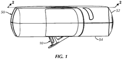
Fig. 1 is an elevational view of a wearable injector, having a needle shield in accordance with a first embodiment of the present disclosure movably mounted thereto; -
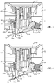
Fig. 2 is a cross-sectional view of the injector and needle shield ofFig. 1 , taken along the sectional line 2-2 ofFig. 1 , with an injection needle of the injector in a retracted position thereof and the needle shield in a second position thereof; -
Fig. 3 is a top and side perspective view of the needle shield ofFig. 1 ; -
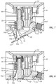
Fig. 4 is an enlarged, partial cross-sectional view of the injector and needle shield ofFig. 1 , taken along the sectional line 2-2 ofFig. 1 , with the injection needle in a injection position thereof and the needle shield in a first position thereof; -
Fig. 5 is an enlarged, partial cross-sectional view of the injector and needle shield ofFig. 1 , taken along the sectional line 2-2 ofFig. 1 , with the injection needle in the injection position thereof and the needle shield returning from the first position thereof to the second position thereof; -
Fig. 6 is an enlarged, partial cross-sectional view of the injector and needle shield ofFig. 1 , taken along the sectional line 2-2 ofFig. 1 , with the injection needle in the injection position thereof and the needle shield further traveled from the first position thereof to the second position thereof relative toFig. 5 ; -
Fig. 7 is an enlarged, partial cross-sectional view of the injector and needle shield ofFig. 1 , taken along the sectional line 2-2 ofFig. 1 , with the injection needle in the injection position thereof and the needle shield in the second position thereof; -
Fig. 8 is an enlarged, partial cross-sectional view of the injector and needle shield ofFig. 1 , taken along the sectional line 2-2 ofFig. 1 , with needle shield moved from the second position thereof substantially back to the first position thereof and axially translating the injection needle therewith substantially back to the retracted position thereof; -
Fig. 9 is an enlarged, partial cross-sectional view of the an injector and a needle shield in accordance with a second example not according to the invention of the present disclosure, taken along the sectional line 2-2 ofFig. 1 , with the needle hub being retracted by the needle shield (in broken line) and the needle hub clearing the needle shield (in solid line); and -
Fig. 10 is an enlarged, partial cross-sectional view of the injector and the needle shield ofFig. 9 , taken along the sectional line 2-2 ofFig. 1 , with needle shield being moved from the second position thereof back to the first position thereof and axially translating the needle hub therewith back to the retracted position thereof. - Certain terminology is used in the following description for convenience only and is not limiting. The words "lower," "bottom," "upper" and "top" designate directions in the drawings to which reference is made. The words "inwardly," "outwardly," "upwardly" and "downwardly" refer to directions toward and away from, respectively, the geometric center of the injector, and designated parts thereof, in accordance with the present disclosure. Unless specifically set forth herein, the terms "a," "an" and "the" are not limited to one element, but instead should be read as meaning "at least one." The terminology includes the words noted above, derivatives thereof and words of similar import.
- It should also be understood that the terms "about," "approximately," "generally," "substantially" and like terms, used herein when referring to a dimension or characteristic of a component of the disclosure, indicate that the described dimension/characteristic is not a strict boundary or parameter and does not exclude minor variations therefrom that are functionally similar. At a minimum, such references that include a numerical parameter would include variations that, using mathematical and industrial principles accepted in the art (e.g., rounding, measurement or other systematic errors, manufacturing tolerances, etc.), would not vary the least significant digit.
- Referring to the drawings in detail, wherein like numerals indicate like elements throughout, there is shown in
Figs. 1-8 an injection needle shield, generally designated 10, in accordance with a first embodiment of the present disclosure. Generally, theinjection needle shield 10 is employed with a wearable injector (patch injector) 50, such as, for example, without limitation, a wearable drug injector, but the disclosure is not so limited. At a minimum, theinjection needle shield 10 may alternatively be employed in other injector configurations. - As should be understood by those of ordinary skill in the art, and as best shown in
Fig. 2 , aninjector 50 generally comprises ahousing 52 having asurface 54 configured to contact a skin surface of a user (not shown), e.g., a patient, thesurface 54 having an opening 54a therein. As shown, aneedle hub 56, e.g., apolymeric needle hub 56, is movably mounted within theinjector housing 52 and aninjection needle 58 is supported by themovable needle hub 56. In one non-limiting example, theinjection needle 58 may be at least a 27 gauge needle. Theneedle hub 56 and theinjection needle 58 are axially translatable along an axis A, extending substantially perpendicularly to thesurface 54, between a retracted position (Fig. 2 ), wherein at least atip 58a of theinjection needle 58 is contained within theinjector housing 52, and an injection position (Figs. 4-6 ), wherein at least thetip 58a of theinjection needle 58 protrudes from theinjector housing 52 through the opening 54a and through anaperture 14 of the needle shield 10 (as will be explained in further detail below). - A
biasing member 60 is operatively connected with theinjection needle 58 to drive theneedle hub 56 and theinjection needle 58 from the retracted position to the injection position. In the illustrated embodiment, thebiasing member 60 takes the form of a coil spring expandable from a contracted state (Fig. 2 ) to an expanded state (Fig. 4 ). In the illustrated embodiment, thecoil spring 60 is mounted between theneedle hub 56 and a depressibleactivation button assembly 62 of theinjector 50, i.e., thespring 60 abuts theactivation button assembly 62 at one end and abuts theneedle hub 56 at an opposing end. In the contracted, i.e., energy storing, state thereof, thecoil spring 60 is prevented from driving theneedle hub 56 and theinjection needle 58 into the injection position. Upon release into the expanded, i.e., an energy releasing, state thereof (generally by depressing the activation button assembly 62), thecoil spring 60 drives theneedle hub 56 and theinjection needle 58 into the injection position. As should be understood by those of ordinary skill in the art, the biasingmember 60 may alternatively take the form of other members capable of storing and releasing a biasing force. Non-limiting examples include other springs (e.g., torsion or leaf springs), elastic bands, and the like. Alternatively, the biasingmember 60 may take the form of an actuator configured to apply a translational force onto theneedle hub 56 and theinjection needle 58. - Turning to the
needle shield 10, theneedle shield 10, e.g., apolymeric needle shield 10, is movably connected to theinjector housing 52 in a manner well understood by those of ordinary skill in the art. In the illustrated embodiment, theneedle shield 10 is pivotably attached to theinjector housing 52, e.g., via apin connector 53 proximate an end of theneedle shield 10, proximate theopening 54a of theskin contacting surface 54. Theneedle shield 10 is movable between a first position and a second position. In the first position (Fig. 4 ), theneedle shield 10 extends generally flush with theskin contacting surface 54 of theinjector 50, but the disclosure is not so limited. In the second position (Figs. 1 ,2 ,7 ), theneedle shield 10 is pivoted away, i.e., downwardly, with respect to the axis A, from theskin contacting surface 54. In the second position, theaperture 14 of theneedle shield 10 is elevationally lower than thetip 58a of theinjection needle 58, with respect to the axis A, in any position of theinjection needle 58. As will be explained in further detail below, when theneedle shield 10 is in the second position and theinjection needle 58 is in the injection position, theneedle shield 10 covers thetip 58a of the injection needle 58 (Fig. 7 ). In the illustrated embodiment, theneedle shield 10 is biased by acoil spring 64 to the second position thereof, but the disclosure is not so limited. Alternatively, theneedle shield 10 may be biased into the second position thereof by another form of biasing member (such as, for example, without limitation, as identified above as alternative biasing members 60) or merely by gravitational force. - As shown best in
Fig. 3 , theneedle shield 10 includes abase surface 12 defining theaperture 14 therein. Theneedle shield 10 further includes at least one post 16 (a pair ofposts 16 in the illustrated embodiment) extending upwardly from thebase surface 12. A cantileveredarm 18 extends downwardly from the post(s) 16 toward thebase surface 12. The cantileveredarm 18 includes a flangedfree end 18a, i.e., the free end of thearm 18 comprises aflange 18a extending generally laterally relative to thearm 18. The cantileveredarm 18 is dimensioned such that theflanged end 18a is positioned in theneedle shield aperture 14 and the laterally extendingflange 18a is angled to extend substantially along the same plane as the plane of extension of thebase surface 12, thereby partially blocking theneedle shield aperture 14. - Prior to placement of the
injector 50 on the skin surface of a user, theinjection needle 58 is blocked from extending through the needle shield aperture 14 (Fig. 2 ). That is, when theneedle shield 10 is in the second position, theinjection needle 58 is either not axially aligned with theaperture 14 or the flangedfree end 18a of the cantileveredarm 18 blocks the pathway of theinjection needle 58 through theaperture 14. Conversely, when theinjector 50 is placed on the skin surface of a user (prior to injection), moving theneedle shield 10 to the first position thereof (against the force biasing theneedle shield 10 into the second position), theneedle shield aperture 14 axially aligns with theinjection needle 58. That is, when theneedle shield 10 is moved to the first position thereof and theinjection needle 58 is in the retracted position thereof, a portion of theneedle shield aperture 14 unblocked by the flangedfree end 18a of the cantileveredarm 18 is axially aligned with theinjection needle 58. Theflanged end 18a clears theinjection needle 58 in such configuration. Accordingly, when theinjector 50 is placed on the user's skin surface, theinjection needle 58 may be moved to the injection position (Fig. 4 ), such that theinjection needle 58 extends through theopening 54a of theinjector 50, through theneedle shield aperture 14 and into the user as theinjection needle 58 is driven into the injection position thereof. - After injection, e.g., of medicament, is complete, the user (or another individual) removes the
injector 50 from the skin surface of the user. Accordingly, as theinjector 50 is removed from the skin surface (and while theinjection needle 58 remains in the injection position thereof), the biasing force (either gravitational force or the biasing force of the spring 64) also returns theneedle shield 10 to the second position thereof. Progressive movement of theneedle shield 10 under the biasing force from the first position (where theinjection needle 58 is aligned with an unblocked portion of the needle shield aperture 14) to the second position (wherein theinjection needle 58 is either not axially aligned with theneedle shield aperture 14 or the flangedfree end 18a of the cantileveredarm 18 blocks the pathway of theinjection needle 58 through the aperture 14) progressively moves at least the unblocked portion of theneedle shield aperture 14 out of axial alignment with theinjection needle 58. - As shown between
Figs. 5 and 6 , theflanged end 18a of the cantileveredarm 18 comes into contact with theinjection needle 58 duringneedle shield 10 movement from the first position (Fig. 4 ) toward the second position (Fig. 7 ) with theinjection needle 58 in the injection position. The cantileveredarm 18 is constructed to be elastically flexible, and is more flexible than theinjection needle 58. That is, theinjection needle 58 is constructed to define a greater bending stiffness, i.e., resistance against bending deformation, than the cantileveredarm 18, in a manner well understood by those of ordinary skill in the art. For example, the cantileveredarm 18 may be constructed of a polymeric material and theinjection needle 58 may be constructed of a metal material that exhibits a greater bending stiffness than the bending stiffness of the polymeric material of the cantileveredarm 18. The cantileveredarm 18 is, therefore, more deflectable than theinjection needle 58. - Accordingly, when the
injection needle 58 is in the injection position and comes into contact with theflanged end 18a of the cantilevered arm 18 (Fig. 5 ), as theneedle shield 10 moves from the first position back to the second position, theinjection needle 58 deflects (Fig. 6 ), i.e., elastically flexes, the cantileveredarm 18 out of an unflexed resting position thereof. Deflection of the cantileveredarm 18 temporarily moves theflanged end 18a aside, enlarging the unblocked portion of theneedle shield aperture 14, to permit theneedle shield 10 to pivot beyond theinjection needle 58 and reach the second position thereof. As theneedle shield 10 clears thetip 58a of theinjection needle 58 and theinjection needle 58 disengages the cantileveredarm 18, the cantileveredarm 18 returns to the unflexed resting position thereof (Fig. 7 ). As shown inFig. 7 , return of the cantileveredarm 18 to the unflexed resting position thereof when theneedle shield 10 returns to the second position thereof results in the flangedfree end 18a of the cantileveredarm 18 returning to blocking the pathway of theinjection needle 58 through theneedle shield aperture 14. - As explained previously, the
needle shield 10 covers thetip 58a of theinjection needle 58 when theneedle shield 10 is in the second position and theinjection needle 58 is in the injection position, thereby protecting the user or other individual from inadvertent contact with thetip 58a of the usedinjection needle 58 that may otherwise injure or infect the individual. After theinjector 50 is removed from the skin surface of the user, and theneedle shield 10 returns to the second position thereof to cover theinjection needle tip 58a, however, inadvertent subsequent contact with theneedle shield 10 with a force countering and overcoming the biasing force of thespring 64 moves theneedle shield 10 back toward the first position thereof, i.e., collapse the needle shield. - As shown in
Fig. 8 , subsequent collapse of theneedle shield 10 from the second position toward the first position thereof, advantageously axially translates theneedle hub 56 and theinjection needle 58 back toward the retracted position thereof to preclude theinjection needle 58 from potentially extending beyond theneedle shield 10. As shown inFig. 8 , the flangedfree end 18a of the cantileveredarm 18 directly contacts theinjection needle 58, e.g., contacts thetip 58a, upon such movement. In some embodiments, theinjection needle 58 defines a greater stiffness than the stiffness of thecoil spring 60 in a manner well understood by those of ordinary skill in the art. For example, theinjection needle 58 may be constructed of a material that defines a stiffness greater than a stiffness of thecoil spring 60 and/or acoil spring 60 may be selected that defines a weaker stiffness than theinjection needle 58. - Accordingly, as shown in
Fig. 8 , contact of theneedle shield 10 with theinjection needle 58 during subsequent collapse of theneedle shield 10 from the second position to the first position pushes theinjection needle 58 and theneedle hub 56 back toward the retracted position thereof, compressing thecoil spring 60 back toward the contracted state, rather than merely bending theinjection needle 58. In some cases, theinjection needle 58 may also bend at least slightly, while moving back toward theinjector housing 52 in addition to predominantly contracting thecoil spring 60 to retract theneedle hub 56 and theinjection needle 58. Alternatively, theinjection needle 58 may be supported against bending to cause retraction of theneedle hub 56 and theinjection needle 58 rather than bending of theinjection needle 58. For example, the cantileveredarm 18 may be positioned to reduce or prevent bending of theinjection needle 58. As should be understood by those of ordinary skill in the art, however, theneedle shield 10 may be configured such that a different portion of theshield 10, e.g., thebase surface 12, contacts theinjection needle 58 upon such movement to axially translate theneedle hub 56 and theinjection needle 58 back toward the retracted position. -
Figs. 9-10 illustrate an example of theneedle shield 110, which does not form part of the invention. The reference numerals of the example (for both theinjector 150 and the needle shield 110) are distinguishable from those of the above-described first embodiment (Figs. 1-8 ) by a factor of one-hundred (100), but otherwise indicate the same elements as indicated above, except as otherwise specified. Theneedle shield 110 of the present example is substantially similar to that of the earlier embodiment. Therefore, the description of certain similarities and modes of operation between the embodiment and the example may be omitted herein for the sake of brevity and convenience, and, therefore, is not limiting. - One difference of the
needle shield 110 over the embodiment ofFigs. 1-8 , is that when theneedle shield 110 is in the second position thereof and theneedle hub 156 and theinjection needle 158 are in the injection position, movement of theneedle shield 110 back toward the first position indirectly axially translates (retracts) theinjection needle 158 back toward the retracted position. - As shown in
Figs. 9 and 10 , theneedle shield 110 comprises acantilevered arm 118 extending upwardly from thebase surface 112 of theneedle shield 110 toward theneedle hub 156. Thecantilevered arm 118 defines a flangedfree end 118a at an upper end thereof. That is, aflange 118a extends laterally from the cantileveredarm 18 at, or proximate, the upper free end thereof. Thecantilevered arm 118 is configured to engage theneedle hub 156, rather than theinjection needle 158, during movement of theneedle shield 110 from the second position thereof toward the first position thereof when theinjection needle 158 is in the injection position, thereby axially translating theneedle hub 156 back into theinjector housing 152 to retract theneedle hub 156 and theinjection needle 158. - Conversely, prior to injection (
Fig. 9 -arm 118 drawn in solid line), theneedle hub 156 clears the cantileveredarm 118. That is, thecantilevered arm 118 is positioned such that when theneedle hub 156 and theinjection needle 158 are in the retracted position, thecantilevered arm 118 does not engage, or otherwise interfere with, theneedle hub 156 during movement of theneedle shield 110 from the second position thereof to the first position thereof, e.g., while initially placing theinjector 150 on the body of the user. Thereafter thecantilevered arm 118 also does not interfere with movement of theneedle hub 156 and theinjection needle 158 from the retraction position to the injection position for injection. - After injection, when the
injector 150 is removed from the user's skin and theneedle shield 110 has returned to the second position thereof, if theneedle shield 110 is pushed back toward the first position, as shown inFig. 10 , thecantilevered arm 118 contacts theneedle hub 156 and retracts theneedle hub 156 and theinjection needle 158 toward the retracted position (Fig. 9 -arm 118 drawn in broken lines). In the illustrated example, theneedle hub 156 comprises aflanged member 156a extending therefrom configured to engage theflanged end 118a of the cantileveredarm 118, but the disclosure is not so limited. - It will be appreciated by those skilled in the art that changes could be made to the embodiments described above without departing from the broad inventive concept thereof. It is understood, therefore, that this disclosure is not limited to the particular embodiments disclosed, but it is intended to cover modifications within the scope of the appended claims.
Claims (13)
- An injector (50, 150) comprising:an injector housing (52, 152) having a surface (54, 154) configured to contact a skin surface of a user, the surface (54, 154) having an opening (54a, 154a) therein;a needle hub (56, 156) movably mounted within the injector housing (52, 152);an injection needle (58, 158) supported by the movable needle hub (56, 156), the needle hub (56, 156) and the injection needle (58, 158) being axially translatable between a retracted position, wherein at least a tip (58a, 158a) of the injection needle (58, 158) is contained within the injector housing (52, 152), and an injection position, wherein at least the tip (58a, 158a) of the injection needle (58, 158) protrudes from the injector housing (52, 152);a needle shield (10, 110) having an aperture (14, 114), the needle shield (10, 110) being movably connected to the injector housing (52, 152) and movable between a first position and a second position;the needle hub (56, 156) and the injection needle (58, 158) axially translate along an axis (A) extending substantially perpendicularly to the surface (54, 154) from the retracted position to the injection position;the injection needle (58, 158) extends through the needle shield aperture (14, 114) in the injection position of the injection needle (58, 158) and the first position of the needle shield (10, 110), and the injection needle (58, 158) is blocked from extending through the needle shield aperture (14, 114) in the second position of the needle shield (10, 110),characterized in that: the needle shield (10) includes a cantilevered arm (18), the cantilevered arm (18) having a flanged free end (18a) partially blocking the needle shield aperture (14), the flanged free end (18a) clearing the injection needle (58) in the first position of the needle shield (10), and the flanged free end (18a) blocking extension of the injection needle (58) through the needle shield aperture (14) in the second position of the needle shield (10), andwhen the needle shield (10, 110) is in the second position and the needle hub (56, 156) and the injection needle (58, 158) are in the injection position, the needle shield (10, 110) covers the tip (58a, 158a) of the injection needle (58, 158) and subsequent movement of the needle shield (10, 110) toward the first position axially translates the needle hub (56, 156) and the injection needle (58, 158) back toward the retracted position from the injection position, along the axis (A), wherein the needle shield (10) directly contacts the injection needle (58) to axially translate the needle hub (56) and the injection needle (58) back toward the retracted position.
- The injector of claim 1, further comprising a biasing member (60, 160) operatively connected with the injection needle (58, 158) to axially translate the needle hub (56, 156) and the injection needle (58, 158) from the retracted position to the injection position.
- The injector of claim 2, wherein the biasing member (60, 160) applies a biasing force to drive the needle hub (56, 156) and the injection needle (58, 158) from the retracted position to the injection position, and when the needle shield (10, 110) is in the second position and the needle hub (56, 156) and the injection needle (58, 158) are in the injection position, subsequent movement of the needle shield (10, 110) from the second position toward the first position, with a force countering and overcoming the biasing force of the biasing member (60, 160), axially translates the needle hub (56, 156) and the injection needle (58, 158) back toward the retracted position.
- The injector of claim 1, wherein when the needle shield (10) is in the second position and the needle hub (56) and the injection needle (58) are in the injection position, the flanged free end (18a) of the cantilevered arm (18) contacts the tip (58a) of the injection needle (58) to axially translate the needle hub (56) and the injection needle (58) back toward the retracted position, upon subsequent movement of the needle shield (10) toward the first position.
- The injector of claim 1, wherein the cantilevered arm (18) is elastically flexible, and wherein the cantilevered arm (18) is more flexible than the injection needle (58).
- The injector of claim 5, wherein when the injection needle (58) is in the injection position, the injection needle (58) engages and elastically flexes the cantilevered arm (18) out of an unflexed resting position thereof during movement of the needle shield (10) from the first position to the second position, and wherein the injection needle (58) disengages the cantilevered arm (18) in the second position of the needle shield (10), whereby the cantilevered arm (18) returns to the unflexed resting position thereof.
- The injector of claim 6, wherein when the injection needle (58) is in the injection position, the injection needle (58) engages the flanged free end (18a) of the cantilevered arm (18) during movement of the needle shield (10) from the first position to the second position.
- The injector of claim 1, wherein when the needle shield (110) is in the second position and the needle hub (156) and the injection needle (158) are in the injection position, subsequent movement of the needle shield (110) toward the first position indirectly axially translates the injection needle (158) back toward the retracted position.
- The injector of claim 1, wherein the needle shield (10, 110) is generally flush with surface (54, 154) of the injector housing (52, 152) in the first position, and the needle shield (10. 110) is pivoted away from the surface (54, 154) of the injector housing (52, 152) in the second position.
- The injector of claim 1, wherein the needle shield (10, 110) is biased by a force into the second position thereof.
- The injector of claim 2, wherein the biasing member (60, 160) is a coil spring expandable from a contracted state to an expanded state to axially translate the needle hub (56, 156) and the injection needle (58, 158) from the retracted position to the injection position.
- The injector of claim 11, wherein when the needle shield (10, 110) is in the second position and the needle hub (56, 156) and the injection needle (58, 158) are in the injection position, subsequent movement of the needle shield (10, 110) toward the first position that axially translates the needle hub (56, 156) and the injection needle (58, 158) back toward the retracted position also compresses the coil spring (60, 160) back toward the contracted state.
- The injector of claim 11, wherein the injection needle (58, 158) defines a stiffness greater than a stiffness of the coil spring (60, 160).
Priority Applications (1)
| Application Number | Priority Date | Filing Date | Title |
|---|---|---|---|
| EP21197374.8A EP3964252A1 (en) | 2017-05-30 | 2018-05-30 | Needle shield for injection needle retraction |
Applications Claiming Priority (2)
| Application Number | Priority Date | Filing Date | Title |
|---|---|---|---|
| US201762512474P | 2017-05-30 | 2017-05-30 | |
| PCT/US2018/035000 WO2018222636A1 (en) | 2017-05-30 | 2018-05-30 | Needle shield for injection needle retraction |
Related Child Applications (1)
| Application Number | Title | Priority Date | Filing Date |
|---|---|---|---|
| EP21197374.8A Division EP3964252A1 (en) | 2017-05-30 | 2018-05-30 | Needle shield for injection needle retraction |
Publications (2)
| Publication Number | Publication Date |
|---|---|
| EP3630237A1 EP3630237A1 (en) | 2020-04-08 |
| EP3630237B1 true EP3630237B1 (en) | 2021-10-20 |
Family
ID=62598099
Family Applications (2)
| Application Number | Title | Priority Date | Filing Date |
|---|---|---|---|
| EP21197374.8A Pending EP3964252A1 (en) | 2017-05-30 | 2018-05-30 | Needle shield for injection needle retraction |
| EP18730955.4A Active EP3630237B1 (en) | 2017-05-30 | 2018-05-30 | Needle shield for injection needle retraction |
Family Applications Before (1)
| Application Number | Title | Priority Date | Filing Date |
|---|---|---|---|
| EP21197374.8A Pending EP3964252A1 (en) | 2017-05-30 | 2018-05-30 | Needle shield for injection needle retraction |
Country Status (5)
| Country | Link |
|---|---|
| US (1) | US11389598B2 (en) |
| EP (2) | EP3964252A1 (en) |
| JP (2) | JP7009513B2 (en) |
| CN (2) | CN115634342A (en) |
| WO (1) | WO2018222636A1 (en) |
Families Citing this family (5)
| Publication number | Priority date | Publication date | Assignee | Title |
|---|---|---|---|---|
| PL1762259T3 (en) | 2005-09-12 | 2011-03-31 | Unomedical As | Inserter for an infusion set with a first and second spring units |
| WO2012123274A1 (en) | 2011-03-14 | 2012-09-20 | Unomedical A/S | Inserter system with transport protection |
| US20190275236A1 (en) * | 2018-03-08 | 2019-09-12 | Eyal BARMAIMON | Full path rigid needle |
| SG11202111673SA (en) | 2019-05-20 | 2021-11-29 | Unomedical As | Rotatable infusion device and methods thereof |
| USD1007676S1 (en) | 2021-11-16 | 2023-12-12 | Regeneron Pharmaceuticals, Inc. | Wearable autoinjector |
Citations (1)
| Publication number | Priority date | Publication date | Assignee | Title |
|---|---|---|---|---|
| US20140228780A1 (en) * | 2010-01-19 | 2014-08-14 | Medimop Medical Projects Ltd. | Needle assembly for drug pump |
Family Cites Families (20)
| Publication number | Priority date | Publication date | Assignee | Title |
|---|---|---|---|---|
| GB9021075D0 (en) | 1990-09-27 | 1990-11-07 | Frontier Plastics South Wales | Improvements relating to sharps disposal containers |
| CN1193804C (en) | 1998-09-23 | 2005-03-23 | L·R·科赫 | Needle point guard safety cap assembly |
| US7530964B2 (en) | 2000-06-30 | 2009-05-12 | Elan Pharma International Limited | Needle device and method thereof |
| CN100479875C (en) | 2002-07-22 | 2009-04-22 | 贝克顿·迪金森公司 | Patch-like infusion device |
| US8512287B2 (en) | 2003-07-22 | 2013-08-20 | Becton, Dickinson And Company | Patch-like infusion device |
| US7513888B2 (en) | 2004-02-17 | 2009-04-07 | Smiths Medical Asd, Inc. | Needle guards |
| CN2748099Y (en) | 2004-10-19 | 2005-12-28 | 丹阳市共创医疗器械科技有限公司 | Safety syringe with automatic retractable needle |
| US8016796B2 (en) | 2005-05-27 | 2011-09-13 | Smiths Medical Asd, Inc. | Safety needle device with snap feature and method of making same |
| US9056188B2 (en) | 2006-11-22 | 2015-06-16 | Becton, Dickinson And Company | Needle shielding flag structures |
| JP5102350B2 (en) * | 2007-04-30 | 2012-12-19 | メドトロニック ミニメド インコーポレイテッド | Reservoir filling / bubble management / infusion medium delivery system and method using the system |
| US7713243B2 (en) | 2007-09-25 | 2010-05-11 | Becton, Dickinson And Company | Tip shield for needle stick prevention |
| ES2788079T3 (en) | 2007-11-21 | 2020-10-20 | Becton Dickinson Co | Needle safety device |
| CN105107064B (en) | 2010-06-09 | 2021-10-01 | 西兰制药公司 | Fluid delivery device needle retraction mechanism, cartridge and expandable hydraulic fluid seal |
| ES2627509T3 (en) | 2010-11-19 | 2017-07-28 | Eli Lilly And Company | Needle loader for medication injection device |
| US9072827B2 (en) * | 2012-03-26 | 2015-07-07 | Medimop Medical Projects Ltd. | Fail safe point protector for needle safety flap |
| EP2836260B1 (en) | 2012-04-10 | 2016-05-25 | Carebay Europe Ltd. | Cap assembly |
| WO2014001319A1 (en) | 2012-06-29 | 2014-01-03 | Novo Nordisk A/S | Spring driven injection device |
| EP3074065B1 (en) | 2013-11-26 | 2023-07-26 | Retractable Technologies, Inc. | Frontal attachment device for syringe with rotationally activated retractable needle |
| US9415176B1 (en) | 2015-01-22 | 2016-08-16 | West Pharmaceutical Services, Inc. | Autoinjector having an end-of-dose visual indicator |
| EP3463526A1 (en) * | 2016-06-02 | 2019-04-10 | West Pharma. Services Il, Ltd. | Three position needle retraction |
-
2018
- 2018-05-30 US US16/617,819 patent/US11389598B2/en active Active
- 2018-05-30 JP JP2019566222A patent/JP7009513B2/en active Active
- 2018-05-30 EP EP21197374.8A patent/EP3964252A1/en active Pending
- 2018-05-30 WO PCT/US2018/035000 patent/WO2018222636A1/en active Application Filing
- 2018-05-30 CN CN202211153963.6A patent/CN115634342A/en active Pending
- 2018-05-30 CN CN201880034803.5A patent/CN111065428B/en active Active
- 2018-05-30 EP EP18730955.4A patent/EP3630237B1/en active Active
-
2022
- 2022-01-12 JP JP2022002872A patent/JP7304445B2/en active Active
Patent Citations (1)
| Publication number | Priority date | Publication date | Assignee | Title |
|---|---|---|---|---|
| US20140228780A1 (en) * | 2010-01-19 | 2014-08-14 | Medimop Medical Projects Ltd. | Needle assembly for drug pump |
Also Published As
| Publication number | Publication date |
|---|---|
| JP7304445B2 (en) | 2023-07-06 |
| JP2022036230A (en) | 2022-03-04 |
| CN115634342A (en) | 2023-01-24 |
| CN111065428B (en) | 2022-10-11 |
| EP3964252A1 (en) | 2022-03-09 |
| US11389598B2 (en) | 2022-07-19 |
| JP7009513B2 (en) | 2022-01-25 |
| US20200188608A1 (en) | 2020-06-18 |
| WO2018222636A1 (en) | 2018-12-06 |
| EP3630237A1 (en) | 2020-04-08 |
| JP2020522315A (en) | 2020-07-30 |
| CN111065428A (en) | 2020-04-24 |
Similar Documents
| Publication | Publication Date | Title |
|---|---|---|
| EP3630237B1 (en) | Needle shield for injection needle retraction | |
| JP6480548B2 (en) | Needlestick prevention safety device for injection devices | |
| US5334149A (en) | Post-injection sheath for a hypodermic syringe needle | |
| EP1658008B1 (en) | Improvements relating to lancets | |
| US6432120B1 (en) | Lancet assembly | |
| KR101840625B1 (en) | Safety device for a pre-filled syringe and injection device | |
| CN103079616B (en) | For safety device and the injection device of prepackage type syringe | |
| CA2695412C (en) | Injection device | |
| KR102651644B1 (en) | Support structures, drug delivery devices, and assembly methods | |
| US20030163097A1 (en) | Huber needle with anti-rebound safety mechanism | |
| EP2983748B1 (en) | Medicament delivery device and method of assembling the same | |
| EP0541690A1 (en) | Safety syringe | |
| EP3664870A1 (en) | Injector premature activation blocking mechanism | |
| EP2632513B1 (en) | Safety devices | |
| CN109310825B (en) | Auxiliary device for a medicament delivery device | |
| EP3603706A1 (en) | Safe injecting device and safety mechanism applied thereto | |
| CN115175718A (en) | Disposable safety needle guard | |
| EP4299092A1 (en) | Cap for removing a needle shield attached to a medical container arranged inside a body of an autoinjector | |
| EP4265284A1 (en) | Disposable injection needle | |
| KR20240016328A (en) | Safety clips for medical injection devices | |
| JP2001079085A (en) | Syringe needle protector, syringe needle having syringe needle protector, and medical implement having syringe needle protector |
Legal Events
| Date | Code | Title | Description |
|---|---|---|---|
| STAA | Information on the status of an ep patent application or granted ep patent |
Free format text: STATUS: UNKNOWN |
|
| STAA | Information on the status of an ep patent application or granted ep patent |
Free format text: STATUS: THE INTERNATIONAL PUBLICATION HAS BEEN MADE |
|
| PUAI | Public reference made under article 153(3) epc to a published international application that has entered the european phase |
Free format text: ORIGINAL CODE: 0009012 |
|
| STAA | Information on the status of an ep patent application or granted ep patent |
Free format text: STATUS: REQUEST FOR EXAMINATION WAS MADE |
|
| 17P | Request for examination filed |
Effective date: 20191118 |
|
| AK | Designated contracting states |
Kind code of ref document: A1 Designated state(s): AL AT BE BG CH CY CZ DE DK EE ES FI FR GB GR HR HU IE IS IT LI LT LU LV MC MK MT NL NO PL PT RO RS SE SI SK SM TR |
|
| AX | Request for extension of the european patent |
Extension state: BA ME |
|
| DAV | Request for validation of the european patent (deleted) | ||
| DAX | Request for extension of the european patent (deleted) | ||
| STAA | Information on the status of an ep patent application or granted ep patent |
Free format text: STATUS: EXAMINATION IS IN PROGRESS |
|
| 17Q | First examination report despatched |
Effective date: 20200904 |
|
| STAA | Information on the status of an ep patent application or granted ep patent |
Free format text: STATUS: EXAMINATION IS IN PROGRESS |
|
| GRAP | Despatch of communication of intention to grant a patent |
Free format text: ORIGINAL CODE: EPIDOSNIGR1 |
|
| STAA | Information on the status of an ep patent application or granted ep patent |
Free format text: STATUS: GRANT OF PATENT IS INTENDED |
|
| INTG | Intention to grant announced |
Effective date: 20210507 |
|
| GRAS | Grant fee paid |
Free format text: ORIGINAL CODE: EPIDOSNIGR3 |
|
| GRAA | (expected) grant |
Free format text: ORIGINAL CODE: 0009210 |
|
| STAA | Information on the status of an ep patent application or granted ep patent |
Free format text: STATUS: THE PATENT HAS BEEN GRANTED |
|
| AK | Designated contracting states |
Kind code of ref document: B1 Designated state(s): AL AT BE BG CH CY CZ DE DK EE ES FI FR GB GR HR HU IE IS IT LI LT LU LV MC MK MT NL NO PL PT RO RS SE SI SK SM TR |
|
| REG | Reference to a national code |
Ref country code: GB Ref legal event code: FG4D |
|
| REG | Reference to a national code |
Ref country code: CH Ref legal event code: EP |
|
| REG | Reference to a national code |
Ref country code: IE Ref legal event code: FG4D |
|
| REG | Reference to a national code |
Ref country code: DE Ref legal event code: R096 Ref document number: 602018025318 Country of ref document: DE |
|
| REG | Reference to a national code |
Ref country code: AT Ref legal event code: REF Ref document number: 1439401 Country of ref document: AT Kind code of ref document: T Effective date: 20211115 |
|
| REG | Reference to a national code |
Ref country code: LT Ref legal event code: MG9D |
|
| REG | Reference to a national code |
Ref country code: NL Ref legal event code: MP Effective date: 20211020 |
|
| REG | Reference to a national code |
Ref country code: AT Ref legal event code: MK05 Ref document number: 1439401 Country of ref document: AT Kind code of ref document: T Effective date: 20211020 |
|
| PG25 | Lapsed in a contracting state [announced via postgrant information from national office to epo] |
Ref country code: RS Free format text: LAPSE BECAUSE OF FAILURE TO SUBMIT A TRANSLATION OF THE DESCRIPTION OR TO PAY THE FEE WITHIN THE PRESCRIBED TIME-LIMIT Effective date: 20211020 Ref country code: LT Free format text: LAPSE BECAUSE OF FAILURE TO SUBMIT A TRANSLATION OF THE DESCRIPTION OR TO PAY THE FEE WITHIN THE PRESCRIBED TIME-LIMIT Effective date: 20211020 Ref country code: FI Free format text: LAPSE BECAUSE OF FAILURE TO SUBMIT A TRANSLATION OF THE DESCRIPTION OR TO PAY THE FEE WITHIN THE PRESCRIBED TIME-LIMIT Effective date: 20211020 Ref country code: BG Free format text: LAPSE BECAUSE OF FAILURE TO SUBMIT A TRANSLATION OF THE DESCRIPTION OR TO PAY THE FEE WITHIN THE PRESCRIBED TIME-LIMIT Effective date: 20220120 Ref country code: AT Free format text: LAPSE BECAUSE OF FAILURE TO SUBMIT A TRANSLATION OF THE DESCRIPTION OR TO PAY THE FEE WITHIN THE PRESCRIBED TIME-LIMIT Effective date: 20211020 |
|
| PG25 | Lapsed in a contracting state [announced via postgrant information from national office to epo] |
Ref country code: IS Free format text: LAPSE BECAUSE OF FAILURE TO SUBMIT A TRANSLATION OF THE DESCRIPTION OR TO PAY THE FEE WITHIN THE PRESCRIBED TIME-LIMIT Effective date: 20220220 Ref country code: SE Free format text: LAPSE BECAUSE OF FAILURE TO SUBMIT A TRANSLATION OF THE DESCRIPTION OR TO PAY THE FEE WITHIN THE PRESCRIBED TIME-LIMIT Effective date: 20211020 Ref country code: PT Free format text: LAPSE BECAUSE OF FAILURE TO SUBMIT A TRANSLATION OF THE DESCRIPTION OR TO PAY THE FEE WITHIN THE PRESCRIBED TIME-LIMIT Effective date: 20220221 Ref country code: PL Free format text: LAPSE BECAUSE OF FAILURE TO SUBMIT A TRANSLATION OF THE DESCRIPTION OR TO PAY THE FEE WITHIN THE PRESCRIBED TIME-LIMIT Effective date: 20211020 Ref country code: NO Free format text: LAPSE BECAUSE OF FAILURE TO SUBMIT A TRANSLATION OF THE DESCRIPTION OR TO PAY THE FEE WITHIN THE PRESCRIBED TIME-LIMIT Effective date: 20220120 Ref country code: NL Free format text: LAPSE BECAUSE OF FAILURE TO SUBMIT A TRANSLATION OF THE DESCRIPTION OR TO PAY THE FEE WITHIN THE PRESCRIBED TIME-LIMIT Effective date: 20211020 Ref country code: LV Free format text: LAPSE BECAUSE OF FAILURE TO SUBMIT A TRANSLATION OF THE DESCRIPTION OR TO PAY THE FEE WITHIN THE PRESCRIBED TIME-LIMIT Effective date: 20211020 Ref country code: HR Free format text: LAPSE BECAUSE OF FAILURE TO SUBMIT A TRANSLATION OF THE DESCRIPTION OR TO PAY THE FEE WITHIN THE PRESCRIBED TIME-LIMIT Effective date: 20211020 Ref country code: GR Free format text: LAPSE BECAUSE OF FAILURE TO SUBMIT A TRANSLATION OF THE DESCRIPTION OR TO PAY THE FEE WITHIN THE PRESCRIBED TIME-LIMIT Effective date: 20220121 Ref country code: ES Free format text: LAPSE BECAUSE OF FAILURE TO SUBMIT A TRANSLATION OF THE DESCRIPTION OR TO PAY THE FEE WITHIN THE PRESCRIBED TIME-LIMIT Effective date: 20211020 |
|
| REG | Reference to a national code |
Ref country code: DE Ref legal event code: R097 Ref document number: 602018025318 Country of ref document: DE |
|
| PG25 | Lapsed in a contracting state [announced via postgrant information from national office to epo] |
Ref country code: SM Free format text: LAPSE BECAUSE OF FAILURE TO SUBMIT A TRANSLATION OF THE DESCRIPTION OR TO PAY THE FEE WITHIN THE PRESCRIBED TIME-LIMIT Effective date: 20211020 Ref country code: SK Free format text: LAPSE BECAUSE OF FAILURE TO SUBMIT A TRANSLATION OF THE DESCRIPTION OR TO PAY THE FEE WITHIN THE PRESCRIBED TIME-LIMIT Effective date: 20211020 Ref country code: RO Free format text: LAPSE BECAUSE OF FAILURE TO SUBMIT A TRANSLATION OF THE DESCRIPTION OR TO PAY THE FEE WITHIN THE PRESCRIBED TIME-LIMIT Effective date: 20211020 Ref country code: EE Free format text: LAPSE BECAUSE OF FAILURE TO SUBMIT A TRANSLATION OF THE DESCRIPTION OR TO PAY THE FEE WITHIN THE PRESCRIBED TIME-LIMIT Effective date: 20211020 Ref country code: DK Free format text: LAPSE BECAUSE OF FAILURE TO SUBMIT A TRANSLATION OF THE DESCRIPTION OR TO PAY THE FEE WITHIN THE PRESCRIBED TIME-LIMIT Effective date: 20211020 Ref country code: CZ Free format text: LAPSE BECAUSE OF FAILURE TO SUBMIT A TRANSLATION OF THE DESCRIPTION OR TO PAY THE FEE WITHIN THE PRESCRIBED TIME-LIMIT Effective date: 20211020 |
|
| PLBE | No opposition filed within time limit |
Free format text: ORIGINAL CODE: 0009261 |
|
| STAA | Information on the status of an ep patent application or granted ep patent |
Free format text: STATUS: NO OPPOSITION FILED WITHIN TIME LIMIT |
|
| 26N | No opposition filed |
Effective date: 20220721 |
|
| PG25 | Lapsed in a contracting state [announced via postgrant information from national office to epo] |
Ref country code: AL Free format text: LAPSE BECAUSE OF FAILURE TO SUBMIT A TRANSLATION OF THE DESCRIPTION OR TO PAY THE FEE WITHIN THE PRESCRIBED TIME-LIMIT Effective date: 20211020 |
|
| PG25 | Lapsed in a contracting state [announced via postgrant information from national office to epo] |
Ref country code: SI Free format text: LAPSE BECAUSE OF FAILURE TO SUBMIT A TRANSLATION OF THE DESCRIPTION OR TO PAY THE FEE WITHIN THE PRESCRIBED TIME-LIMIT Effective date: 20211020 |
|
| REG | Reference to a national code |
Ref country code: CH Ref legal event code: PL |
|
| REG | Reference to a national code |
Ref country code: BE Ref legal event code: MM Effective date: 20220531 |
|
| PG25 | Lapsed in a contracting state [announced via postgrant information from national office to epo] |
Ref country code: MC Free format text: LAPSE BECAUSE OF FAILURE TO SUBMIT A TRANSLATION OF THE DESCRIPTION OR TO PAY THE FEE WITHIN THE PRESCRIBED TIME-LIMIT Effective date: 20211020 Ref country code: LU Free format text: LAPSE BECAUSE OF NON-PAYMENT OF DUE FEES Effective date: 20220530 Ref country code: LI Free format text: LAPSE BECAUSE OF NON-PAYMENT OF DUE FEES Effective date: 20220531 Ref country code: CH Free format text: LAPSE BECAUSE OF NON-PAYMENT OF DUE FEES Effective date: 20220531 |
|
| PG25 | Lapsed in a contracting state [announced via postgrant information from national office to epo] |
Ref country code: IT Free format text: LAPSE BECAUSE OF FAILURE TO SUBMIT A TRANSLATION OF THE DESCRIPTION OR TO PAY THE FEE WITHIN THE PRESCRIBED TIME-LIMIT Effective date: 20211020 Ref country code: BE Free format text: LAPSE BECAUSE OF NON-PAYMENT OF DUE FEES Effective date: 20220531 |
|
| P01 | Opt-out of the competence of the unified patent court (upc) registered |
Effective date: 20230529 |
|
| PGFP | Annual fee paid to national office [announced via postgrant information from national office to epo] |
Ref country code: IE Payment date: 20230529 Year of fee payment: 6 Ref country code: FR Payment date: 20230525 Year of fee payment: 6 Ref country code: DE Payment date: 20230530 Year of fee payment: 6 |
|
| PGFP | Annual fee paid to national office [announced via postgrant information from national office to epo] |
Ref country code: GB Payment date: 20230529 Year of fee payment: 6 |