EP3629780B2 - Transferring apparatus for transferring and method for transferring of rod-like articles of tobacco industry, and apparatus for conversion of configuration of a stream of such articles - Google Patents
Transferring apparatus for transferring and method for transferring of rod-like articles of tobacco industry, and apparatus for conversion of configuration of a stream of such articles Download PDFInfo
- Publication number
- EP3629780B2 EP3629780B2 EP18737974.8A EP18737974A EP3629780B2 EP 3629780 B2 EP3629780 B2 EP 3629780B2 EP 18737974 A EP18737974 A EP 18737974A EP 3629780 B2 EP3629780 B2 EP 3629780B2
- Authority
- EP
- European Patent Office
- Prior art keywords
- articles
- rod
- transferring
- stream
- slidable
- Prior art date
- Legal status (The legal status is an assumption and is not a legal conclusion. Google has not performed a legal analysis and makes no representation as to the accuracy of the status listed.)
- Active
Links
Images


Classifications
-
- A—HUMAN NECESSITIES
- A24—TOBACCO; CIGARS; CIGARETTES; SIMULATED SMOKING DEVICES; SMOKERS' REQUISITES
- A24C—MACHINES FOR MAKING CIGARS OR CIGARETTES
- A24C5/00—Making cigarettes; Making tipping materials for, or attaching filters or mouthpieces to, cigars or cigarettes
- A24C5/47—Attaching filters or mouthpieces to cigars or cigarettes, e.g. inserting filters into cigarettes or their mouthpieces
- A24C5/478—Transport means for filter- or cigarette-rods in view of their assembling
-
- A—HUMAN NECESSITIES
- A24—TOBACCO; CIGARS; CIGARETTES; SIMULATED SMOKING DEVICES; SMOKERS' REQUISITES
- A24C—MACHINES FOR MAKING CIGARS OR CIGARETTES
- A24C5/00—Making cigarettes; Making tipping materials for, or attaching filters or mouthpieces to, cigars or cigarettes
- A24C5/32—Separating, ordering, counting or examining cigarettes; Regulating the feeding of tobacco according to rod or cigarette condition
- A24C5/322—Transporting cigarettes during manufacturing
- A24C5/327—Construction details of the cigarette transport drum
-
- A—HUMAN NECESSITIES
- A24—TOBACCO; CIGARS; CIGARETTES; SIMULATED SMOKING DEVICES; SMOKERS' REQUISITES
- A24D—CIGARS; CIGARETTES; TOBACCO SMOKE FILTERS; MOUTHPIECES OF CIGARS OR CIGARETTES; MANUFACTURE OF TOBACCO SMOKE FILTERS OR MOUTHPIECES
- A24D3/00—Tobacco smoke filters, e.g. filter tips or filtering inserts; Filters specially adapted for simulated smoking devices; Mouthpieces of cigars or cigarettes
- A24D3/02—Manufacture of tobacco smoke filters
- A24D3/0275—Manufacture of tobacco smoke filters for filters with special features
- A24D3/0287—Manufacture of tobacco smoke filters for filters with special features for composite filters
-
- B—PERFORMING OPERATIONS; TRANSPORTING
- B65—CONVEYING; PACKING; STORING; HANDLING THIN OR FILAMENTARY MATERIAL
- B65G—TRANSPORT OR STORAGE DEVICES, e.g. CONVEYORS FOR LOADING OR TIPPING, SHOP CONVEYOR SYSTEMS OR PNEUMATIC TUBE CONVEYORS
- B65G29/00—Rotary conveyors, e.g. rotating discs, arms, star-wheels or cones
- B65G29/02—Rotary conveyors, e.g. rotating discs, arms, star-wheels or cones for inclined or vertical transit
Definitions
- the object of the invention is a transferring apparatus for transferring and a method for transferring of rod-like articles of the tobacco industry, and an apparatus for conversion of configuration of a stream of such articles.
- rod-like articles such as non-filter cigarettes, filter cigarettes, cigarillos, filter rods made of one kind of material, multi-segment filter rods, cigars etc.
- the semi-finished products manufactured at individual production stages are also referred to as rod-like articles.
- the rod-like articles may be transferred in a mass flow in which the relative position of the articles being transferred is random and variable, however, a part of the machines requires transferring of rod-like articles in streams of individual articles in which the position of neighbouring articles relative to one another is defined. It is possible to transfer the rod-like articles successively one after another so that the axes of the rod-like articles are parallel to the transferring direction, which means that the articles are transferred coaxially.
- Multi-segment filter rods are an example of a rod-like article which is composed of a plurality of rod-like articles.
- the multi-segment filter rods consist of segments made of various kinds of filter materials. Before manufacturing multi-segment rods, the filter rods containing a filter material of one kind are cut into a plurality of short filter segments. The filter segments made of different materials are placed in an appropriate order maintaining defined distances between the segments in order to ultimately manufacture multi-segment rods in successive operations, whereas in a finished rod the segments may abut or there may be distances left between the segments.
- a segment stream forming unit together with the separating cam designed to separate individual segments constitute a feeding apparatus designed to feed the segments to the transferring apparatus, whereas the configuration of the stream from which the separating cam pulls out the segments, one at a time, is such that the segments move coaxially one after another and remain in contact with one another.
- the segments are transferred downwards by means of a transferring wheel with lugs onto the belt conveyor which, in the segment receiving area, is U-shaped in cross-section.
- the belt conveyor constitutes a receiving apparatus on which a second stream of segments with a configuration different from the first stream is formed.
- the stream configuration on the belt conveyor is such that the segments move coaxially at distances, whereas the segments may move at equal distances or the segments may be spaced so that the distances between the segments may have two different values, i.e. may be alternately the same.
- the patent EP2230951B1 has disclosed a transferring disc of a transferring apparatus on which the lugs are arranged uniformly and are used to place the segments at equal distances on the belt conveyor.
- the patent EP2230951B1 has also disclosed a transferring disc on which the lugs are arranged non-uniformly and are used to place the segments at alternately the same distances on the belt conveyor.
- the segments are transferred from the first segment stream uniformly to a place from which they are taken by a lug of the transferring disc.
- every second segment is taken immediately after feeding it to the place from which it is taken by a lug of the transferring disc, and every second segment waits at this place to be taken, which means that a certain time passes between segment feeding and segment being taken by a lug of the transferring disc.
- a problem occurs in the case of feeding of very short segments because, when separating short segments from the segment stream, as a result of mutual friction of neighbouring segments the short segments may rotate in an uncontrolled manner.
- segments which are taken with a delay may also rotate in an uncontrolled manner because the guiding surfaces on which the articles are guided are movable, and the segments are not held on all sides.
- short segments may be transferred and placed on the belt conveyor in an uncontrolled position, in consequence of which a defective rod will be manufactured.
- the control system should detect such rod and it should be rejected from the production.
- a part of the rods with turned segments is not detected and defective filter tips made of them are attached to cigarettes. Such defective cigarettes may get to customers.
- a further apparatus for the transferring of rod-like articles of the tobacco industry is disclosed in document EP 3117722 A1 .
- This invention solves the problem of developing an apparatus for the transferring of rod-like articles and an apparatus for the conversion of configuration of a stream of rod-like articles where such apparatuses will eliminate the risk of manufacture of defective rods.
- This task concerns in particular such rods whose manufacturing requires placing short segments at different distances on the conveyor.
- the object of the invention is a transferring apparatus for transferring of a stream of rod-like articles from an apparatus feeding the rod-like articles to an apparatus receiving the rod-like articles in machines of the tobacco industry.
- the feeding apparatus the rod-like articles are conveyed in a first stream of rod-like articles in which the rod-like articles are arranged in a first configuration
- the receiving apparatus the rod-like articles are conveyed in a second stream of rod-like articles in which the rod-like articles are arranged in a second configuration.
- the apparatus according to the invention comprises a transferring wheel, non-slidable lugs situated on the circumference of the transferring wheel, and a guiding surface to guide the rod-like article.
- the rod-like articles are conveyed axially, tangentially to the guiding surface.
- the apparatus according to the invention is characterised by having a slidable lug being slidable relative to the circumference of the transferring wheel by means of a drive mechanism so that the said slidable lug varies its position relative to an adjacent non-slidable lug.
- the apparatus according to the invention is further characterised in that the slidable lug is attached to an arm being rotatably attached on the axis of rotation of the transferring wheel.
- the apparatus according to the invention is further characterised in that the slidable lug is attached to an arm being attached rotatably eccentrically relative to the axis of rotation of the transferring wheel.
- the apparatus according to the invention is characterised in that the rotary drive mechanism is rotatably or slidably coupled with the arm of the lug at a coupling point, whereas the distance of the coupling point from the axis of rotation of the drive mechanism cyclically varies during rotation of the drive mechanism.
- the apparatus according to the invention is characterised in that the drive mechanism is provided with a drive disc having a guiding groove engaged with a coupling mandrel attached to the arm.
- the apparatus according to the invention is characterised in that the drive disc is attached eccentrically relative to the axis of rotation of the transferring wheel.
- the apparatus according to the invention is characterised by having at least two slidable lugs and at least two non-slidable lugs arranged alternately.
- the apparatus according to the invention is characterised in that the guiding surface is the circumferential surface of the transferring wheel.
- the object of the invention is further an apparatus for the conversion of configuration of a stream of rod-like articles in the machines of the tobacco industry comprising: an apparatus feeding the rod-like articles in which a first stream of the rod-like articles is conveyed and from which the rod-like articles are fed to a transferring apparatus, whereas the rod-like articles in the first stream are arranged in a first configuration. It further comprises a transferring apparatus for the transferring of the rod-like articles according to the invention, whereas the rod-like articles are transferred to a receiving apparatus; and a receiving apparatus for receiving the rod-like articles in which a second stream of the rod-like articles is conveyed, whereas the rod-like articles in the second stream are arranged in a second configuration.
- the method according to the invention is characterised in that during conveying of the rod-like articles in the transferring apparatus the rod-like articles are shifted relative to one another so that the input distances between the successive rod-like articles are varied to the output distances by changing the relative position of the adjacent lugs in the conveying apparatus.
- the invention introduces an advantageous method for controlling the distances between the sequences which may be easily used in existing production lines without the need of introducing a new unit in the line.
- the method according to the invention allows controlling the distances while using a high speed of transfer of the rod-like articles.
- the drive disc 13 may be attached in the axis 11 by means of a bearing or to a shaft.
- the drive mechanism 10 is rotatably and/or slidably coupled at the coupling point K with at least one arm 20 to which the slidable lug 22 is attached.
- the arms 20 provided with the slidable lugs 22 and the transferring wheel 30 are rotatably attached so that the axis of rotation 21 of the arms 20 and the axis of rotation 31 of the transferring wheel 30 overlap, while the drive disc 13 of the drive mechanism 10 is rotatably attached so that its axis of rotation 11 does not overlap the axis of rotation 31 of the transferring wheel 30 and the axis of rotation 21 of the arms 20.
- the grooves 12 are rectilinear grooves, whereas they may have the form of arched grooves.
- the slidable lugs 22 move during the operation of the transferring apparatus 1 with a variable rotational speed, while the non-slidable lugs 33 move with a constant rotational speed of the transferring wheel 30.
- the coupling of the drive disc 13 of the drive mechanism 10 with the arm 20 by means of the coupling mandrel 23 ensures the power transmission from the drive disc 13 of the drive mechanism 10 to the arm 20.
- the rotational movement of the drive disc 13 of the drive mechanism 10 forces the rotational movement of the arms 20 and the slidable lugs 22.
- the coupling of the drive disc 13 of the drive mechanism 10 is slidable due to the movement of the coupling mandrel 23 in the groove 12 and rotatable due to the relative rotational movement of the arm 20 and the drive disc 13 of the drive mechanism 10.
- the coupling point K of the drive disc 13 of the drive mechanism 10 and the arm 20 lying in the axis of the coupling mandrel 23 may be distinguished.
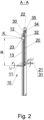
- the distance between the coupling point K and the axis of rotation 11 of the drive disc 13 of the drive mechanism 10 is variable during the rotational movement of the transferring apparatus 1.
- the position of the coupling mandrel 23 in the guiding groove 12 varies. This variation involves an alteration of the distance of the coupling point K from the axis of rotation 11 of the drive disc 13 marked as R in Fig. 2 .
- the coupling mandrel 23 moves along the guiding groove 12, which forces a variation of position of the slidable lug 22 relative to the non-slidable lug 33.
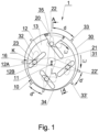
- the original angular distance d between the non-slidable lug 33 and the slidable lug 22 is marked in Fig. 1 .
- the first lugs 33, 22, after making a part of the rotation, will be in the same position as the second lugs 33', 22', and the angular distance d' between them is smaller than the original distance d.
- the angular distance between the lugs 33, 22 varies in the course of rotation of the transferring apparatus.
- Fig. 3 shows an embodiment of the transferring apparatus in a conveying system of the tobacco industry.
- the transferring apparatus 1 shown in Fig. 1 is situated between the feeding apparatus 100 in which the segments are conveyed in the first stream S1 and the receiving apparatus 200 in which the segments are conveyed in the second stream S2.
- the feeding apparatus 100, the transferring apparatus 1 and the receiving apparatus 200 form an apparatus for the conversion of stream configuration in the first embodiment.
- the feeding apparatus 100 comprises a spiral rotary drum 110 for lengthwise feeding of the segments 40 in the first stream S1 and a separating cam 111 to separate an individual segment 40 and deliver such segment to the feeding area 14 (the operation of the spiral drum and the separating cam was described in detail in the patent EP2230951B1 ).
- the separating cam 111 may be replaced with another delivering element, for example with a delivering wheel situated perpendicular to the transferring plane.
- the segments 40 are delivered to the feeding area 14 at a uniform rate so that they can be received at equal distances.
- the distances between the successive segments in the feeding area 14 are the input distances at the transferring apparatus 1.
- the segments 40 are spaced at output distances different from the input distances.
- the length of the output distances varies alternately, with the sum of two consecutive input distances being equal to the sum of two consecutive output distances.
- the configuration of the first stream S1 in the feeding apparatus 100 is such that the segments 40 are fed axially one after another and touch one another.
- the segments 40 move in the second stream S2.
- the segments 40 are fed axially one after another in the conveying direction, they do not abut and are alternately arranged at the distance a or b.
- a variation of configuration of the segment stream from S1 to S2 is made by means of the transferring apparatus 1 according to the invention.
- the segments 40 are transferred in such a way that from the segment stream S1 in the first configuration wherein the segments 40 are spaced at equal distances the segment stream S2 in the second configuration wherein the segments 40 are spaced at different distances is formed.
- a reverse conversion of arrangement configuration of the segments 40 in the streams is also possible, i.e. from a stream with a non-uniform segment arrangement a stream with a uniform segment arrangement may be formed.
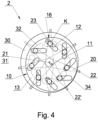
- Fig. 4 shows a second embodiment of the transferring apparatus 2 according to the invention.
- the transferring apparatus 2 has the form of a transferring wheel unit having a guiding wheel 30 with a guiding surface 34 on which the rod-like articles of the tobacco industry are guided.
- the transferring apparatus 2 comprises a drive mechanism 10 rotatably and/or slidably coupled with at least one arm 20 at the coupling point K.
- the transferring wheel has the through holes 32 through which the coupling mandrels 23 pass.
- the coupling unit 16 couples the drive disc 13 of the drive mechanism 10 with the arm 20 by means of the coupling mandrel 23.
- the transferring apparatus 2 comprises eight arms 20, provided with the lugs 22, 22'.
- the movement of the slidable lugs 22, 22' on the circumference of the transferring wheel 30 causes a continuous variation of the distance between the slidable lugs 22, 22'.
- the range of the variation of position of the slidable lugs 22, 22' may be adjusted by selecting relevant geometrical parameters of the coupling unit.
- the transferring apparatus 2 is adapted to convey and change the stream U1 of the rod-like articles from the feeding apparatus 300 into the stream U2 of the rod-like articles fed to the receiving apparatus 200.
- the rod-like articles are in this case filter segments.
- the stream U1 is formed by the segment groups 41, whereas the successive segment groups 41 are situated at the distance e from one another.
- the stream U2 is formed from the segment groups 41, whereas between the segment groups 41 the distance e'", smaller than the distance e, is maintained.
- the feeding apparatus 300 is adapted to convey the segments on a circular, generally arched path.
- the segment groups 41 are situated on the circumferential surface 44 of the wheel 45 and are conveyed on the path of movement by means of the uniformly spaced lugs 46.
- the segment groups 41 are fed to the transferring apparatus 1 in the feeding area 14.
- the transferring apparatus 1 is provided with the lugs of one kind, namely with the slidable lugs 22 being slidable relative to the guiding surface 34.
- the distance between the adjacent segment groups 41 is reduced from the value e via the values e', e" down to e'" decreasing due to the variation of position of the adjacent slidable lugs 22.
- the segment groups 41 at the distances e'" are transferred to the receiving apparatus 200 in the receiving area 15.
- the receiving apparatus 200 is adapted to convey the segments in the stream U2 on a linear path while keeping the distances e'" between the segment groups 41.
- the apparatus comprising the feeding apparatus 300, the transferring apparatus 2 and the receiving apparatus 200 is an apparatus for the conversion of stream configuration of the segment groups 41 conveyed on an arc with distances for the stream configuration of the segment groups 41 in the linear movement with smaller distances between the segment groups 41.
- the transferring apparatus 2 works with a guide 47 which forms a channel for the transferred segment groups 41.
- Fig. 6 presents an apparatus for the conversion of stream configuration in a third embodiment comprising the feeding apparatus 300, the transferring apparatus 3 and the receiving apparatus 200.
- the transferring apparatus 3 is adapted to convert the stream V1 of the segment groups 41 into the segment stream V2, whereas in the stream V2 there are no distances between the segments.
- the stream V1 is conveyed on a circular path.
- the slidable lugs 26 having a smaller thickness than the slidable lugs 22 in the previous embodiments are used, for example the slidable lugs 26 may be designed as steel plates.
- the guiding surface 37 is a cylindrical surface with the axis 36 situated eccentrically relative to the axis 21 on which the arms 27 with the slidable lugs 26 are rotatably attached.
- the guiding surface 37 may be stationary, then the segments will be conveyed by sliding on the guiding surface 37.
- the guiding surface 37 may be rotational with the axis of rotation 36, whereas the guiding surface 37 rotates with a rotational speed equal to the rotational speed of the drive disc 13. Due to the eccentric situation of the guiding surface 37, the slidable lugs 26 protrude above the guiding surface 37 to the height r which varies with the rotation of the slidable lugs 26 around the axis 21.
- the height r decreases to zero or to a value close to zero. Due to the fact that the height r drops to zero, it is possible to push the segment groups 41 close to one another. Pushing the segment groups 41 close to one another in the stream V2 is also possible when the slidable lugs 26 do not go completely below the guiding surface 37 while keeping the linear speed of the receiving apparatus 200 smaller than the speed of the slidable lugs 26. Similar to the previous embodiments, the arms 27 are attached on the axis 21, whereas the drive disc 13 is attached eccentrically on the axis 11.
- the linear speed of the belt conveyor in the receiving apparatus 200 may be equal to or smaller than the speed with which the slidable lugs 26 move.
- the configuration of the stream V2 is such that the segments are conveyed coaxially linearly one after another, the segments touching one another.
- Fig. 7 presents an apparatus for the conversion of stream configuration in a fourth embodiment comprising the feeding apparatus 300, the transferring apparatus 4 and the receiving apparatus 200.
- the transferring apparatus 4 is adapted to convert the stream W1 of the segment groups 41 conveyed at distances s into the stream W2 of segments without distances.
- the lugs 26 like in the third embodiment are used, whereas the arms 28 to which the slidable lugs 26 are attached are fixed on a plurality of axes of rotation 38 arranged around the axis 21.
- the axes of rotation 38 may be arranged in the disc 48 rotatably attached on the axis 21.
- the stationary guiding surface 37' is a cylindrical surface or a cylindrical surface sector with the axis 36 situated eccentrically relative to the axis 21.
- the segment groups 41 are conveyed by sliding on the guiding surface 39.
- the guiding surface 39 may have a circumferential cut-out in which the slidable lugs 26 move. Due to the eccentric arrangment of the guiding surface 39, the slidable lugs 26 protrude above the guiding surface 39 to a different height varying with the rotation of the slidable lugs 26. The slidable lug 26 being in the receiving area 15 does not protrude above the guiding surface 39. As a result, it is possible to push the segment groups 41 close to one another.
- the distances between the segment groups 41 decrease from the value s of the stream W1 via s' and s" due to a change in mutual position of the slidable lugs 26 down to the value s'" equal to zero.
- the segments are conveyed in segment groups 41 on an arc, with the distances s being kept between the groups.
- the configuration of the stream W2 is such that the segments are conveyed coaxially linearly one after another, the segments abutting.
- Fig. 8 shows an apparatus for the conversion of segment stream configuration comprising the feeding apparatus 60 to feed the segment groups 70 or individual segments, the transferring apparatuses 61, 62, 63 and the receiving apparatus 200.
- the input stream Z1 of the segment groups 70 or the individual segments has an input configuration in which the segment groups 70 or the individual segments are conveyed at defined distances h.
- the output stream Z5 has an output configuration in which the segment groups 70 or the individual segments are conveyed at defined distances h'.
- the transferring apparatuses 61, 62, 63 are used to convey the segments respectively in the streams Z2, Z3, Z4, whereas they may reduce the distances between the groups 70 or the segments or keep the distances of the preceding streams.
- the transferring apparatus 61, 62, 63 may be designed according to one of the embodiments of the transferring apparatus 2, 3, 4.
Landscapes
- Manufacturing Of Cigar And Cigarette Tobacco (AREA)
- Specific Conveyance Elements (AREA)
- Cigarettes, Filters, And Manufacturing Of Filters (AREA)
Description
- The object of the invention is a transferring apparatus for transferring and a method for transferring of rod-like articles of the tobacco industry, and an apparatus for conversion of configuration of a stream of such articles.
- In the tobacco industry machines, various kinds of rod-like articles such as non-filter cigarettes, filter cigarettes, cigarillos, filter rods made of one kind of material, multi-segment filter rods, cigars etc. are manufactured. The semi-finished products manufactured at individual production stages are also referred to as rod-like articles. The rod-like articles may be transferred in a mass flow in which the relative position of the articles being transferred is random and variable, however, a part of the machines requires transferring of rod-like articles in streams of individual articles in which the position of neighbouring articles relative to one another is defined. It is possible to transfer the rod-like articles successively one after another so that the axes of the rod-like articles are parallel to the transferring direction, which means that the articles are transferred coaxially. It is possible to transfer the articles one after another so that the axes of the articles are situated transversely to the conveying direction, with the axes of the articles being situated parallel to one another. The distances between the segments and the possibility to transfer the segments in groups or independently of one another may be defined. In view of different production line configurations it is also needed to transfer the articles among the streams, whereas the configuration in the streams may be different for each stream.
- Multi-segment filter rods are an example of a rod-like article which is composed of a plurality of rod-like articles. The multi-segment filter rods consist of segments made of various kinds of filter materials. Before manufacturing multi-segment rods, the filter rods containing a filter material of one kind are cut into a plurality of short filter segments. The filter segments made of different materials are placed in an appropriate order maintaining defined distances between the segments in order to ultimately manufacture multi-segment rods in successive operations, whereas in a finished rod the segments may abut or there may be distances left between the segments. An apparatus for the manufacture of multi-segment filter rods is known from the patent
EP2230951B1 , whereas in that apparatus several streams of rod-like articles with different configurations may be indicated. The rods made of a filter material of one kind are cut into segments which are conveyed in the form of a first stream in which the segments move axially one after another. The segments are fed one by one from the stream by means of a separating cam to a transferring apparatus comprising a transferring wheel provided with lugs which transfers the segments onto a belt conveyor. A segment stream forming unit together with the separating cam designed to separate individual segments constitute a feeding apparatus designed to feed the segments to the transferring apparatus, whereas the configuration of the stream from which the separating cam pulls out the segments, one at a time, is such that the segments move coaxially one after another and remain in contact with one another. The segments are transferred downwards by means of a transferring wheel with lugs onto the belt conveyor which, in the segment receiving area, is U-shaped in cross-section. The belt conveyor constitutes a receiving apparatus on which a second stream of segments with a configuration different from the first stream is formed. The stream configuration on the belt conveyor is such that the segments move coaxially at distances, whereas the segments may move at equal distances or the segments may be spaced so that the distances between the segments may have two different values, i.e. may be alternately the same. The patentEP2230951B1 has disclosed a transferring disc of a transferring apparatus on which the lugs are arranged uniformly and are used to place the segments at equal distances on the belt conveyor. The patentEP2230951B1 has also disclosed a transferring disc on which the lugs are arranged non-uniformly and are used to place the segments at alternately the same distances on the belt conveyor. - The segments are transferred from the first segment stream uniformly to a place from which they are taken by a lug of the transferring disc. In the case of non-uniform feeding of the segments and placing of the segments at different distances on the belt conveyor every second segment is taken immediately after feeding it to the place from which it is taken by a lug of the transferring disc, and every second segment waits at this place to be taken, which means that a certain time passes between segment feeding and segment being taken by a lug of the transferring disc. A problem occurs in the case of feeding of very short segments because, when separating short segments from the segment stream, as a result of mutual friction of neighbouring segments the short segments may rotate in an uncontrolled manner. Furthermore, it may happen that segments which are taken with a delay may also rotate in an uncontrolled manner because the guiding surfaces on which the articles are guided are movable, and the segments are not held on all sides. As a result, short segments may be transferred and placed on the belt conveyor in an uncontrolled position, in consequence of which a defective rod will be manufactured. The control system should detect such rod and it should be rejected from the production. However, a part of the rods with turned segments is not detected and defective filter tips made of them are attached to cigarettes. Such defective cigarettes may get to customers. A further apparatus for the transferring of rod-like articles of the tobacco industry is disclosed in document
EP 3117722 A1 . - This invention solves the problem of developing an apparatus for the transferring of rod-like articles and an apparatus for the conversion of configuration of a stream of rod-like articles where such apparatuses will eliminate the risk of manufacture of defective rods. This task concerns in particular such rods whose manufacturing requires placing short segments at different distances on the conveyor.
- The object of the invention is a transferring apparatus for transferring of a stream of rod-like articles from an apparatus feeding the rod-like articles to an apparatus receiving the rod-like articles in machines of the tobacco industry. In the feeding apparatus the rod-like articles are conveyed in a first stream of rod-like articles in which the rod-like articles are arranged in a first configuration, and in the receiving apparatus the rod-like articles are conveyed in a second stream of rod-like articles in which the rod-like articles are arranged in a second configuration. The apparatus according to the invention comprises a transferring wheel, non-slidable lugs situated on the circumference of the transferring wheel, and a guiding surface to guide the rod-like article. The rod-like articles are conveyed axially, tangentially to the guiding surface. The apparatus according to the invention is characterised by having a slidable lug being slidable relative to the circumference of the transferring wheel by means of a drive mechanism so that the said slidable lug varies its position relative to an adjacent non-slidable lug.
- The apparatus according to the invention is further characterised in that the slidable lug is attached to an arm being rotatably attached on the axis of rotation of the transferring wheel.
- The apparatus according to the invention is further characterised in that the slidable lug is attached to an arm being attached rotatably eccentrically relative to the axis of rotation of the transferring wheel.
- The apparatus according to the invention is characterised in that the rotary drive mechanism is rotatably or slidably coupled with the arm of the lug at a coupling point, whereas the distance of the coupling point from the axis of rotation of the drive mechanism cyclically varies during rotation of the drive mechanism. The apparatus according to the invention is characterised in that the drive mechanism is provided with a drive disc having a guiding groove engaged with a coupling mandrel attached to the arm.
- The apparatus according to the invention is characterised in that the drive disc is attached eccentrically relative to the axis of rotation of the transferring wheel.
- The apparatus according to the invention is characterised by having at least two slidable lugs and at least two non-slidable lugs arranged alternately.
- The apparatus according to the invention is characterised in that the guiding surface is the circumferential surface of the transferring wheel.
- The apparatus according to the invention is characterised in that the guiding surface is a cylindrical surface situated above the circumferential surface of the transferring wheel.
- The object of the invention is further an apparatus for the conversion of configuration of a stream of rod-like articles in the machines of the tobacco industry comprising: an apparatus feeding the rod-like articles in which a first stream of the rod-like articles is conveyed and from which the rod-like articles are fed to a transferring apparatus, whereas the rod-like articles in the first stream are arranged in a first configuration. It further comprises a transferring apparatus for the transferring of the rod-like articles according to the invention, whereas the rod-like articles are transferred to a receiving apparatus; and a receiving apparatus for receiving the rod-like articles in which a second stream of the rod-like articles is conveyed, whereas the rod-like articles in the second stream are arranged in a second configuration.
- The apparatus according to the invention is characterised in that the feeding apparatus is provided with a separating cam designed to feed the rod-like articles and situated in a plane perpendicular to the transferring plane.
- The apparatus according to the invention is further characterised in that the feeding apparatus has a feeding wheel designed to feed the rod-like articles and situated in a plane perpendicular to the transferring plane.
- The apparatus according to the invention is further characterised in that the receiving apparatus is a belt conveyor.
- The object of the invention is further a method for transferring of rod-like articles being conveyed axially from an apparatus feeding rod-like articles to an apparatus receiving the rod-like articles by means of a transferring apparatus provided with a transferring wheel and with lugs wherein the rod-like articles are fed from the feeding apparatus to the transferring apparatus, the rod-like articles are conveyed in the transferring apparatus, giving input distances between the rod-like articles in the transferring apparatus, the rod-like articles are transferred from the transferring apparatus to the receiving apparatus keeping output distances of the transferring apparatus between the successive rod-like articles. The method according to the invention is characterised in that during conveying of the rod-like articles in the transferring apparatus the rod-like articles are shifted relative to one another so that the input distances between the successive rod-like articles are varied to the output distances by changing the relative position of the adjacent lugs in the conveying apparatus.
- The method according to the invention is characterised in that the input distances are uniform, and the output distances are alternately uniform.
- The invention introduces an advantageous method for controlling the distances between the sequences which may be easily used in existing production lines without the need of introducing a new unit in the line. The method according to the invention allows controlling the distances while using a high speed of transfer of the rod-like articles.
- The object of the invention was shown in detail in a preferred embodiment in a drawing in which:
- Fig. 1
- shows a transferring apparatus in a first embodiment;
- Fig. 2
- shows a cross-section through the apparatus of
Fig. 1 ; - Fig. 3
- shows an apparatus for the conversion of configuration in a first embodiment;
- Fig. 4
- shows the transferring apparatus in a second embodiment;
- Fig. 5
- shows the apparatus for the conversion of configuration of the stream in a second embodiment;
- Fig. 6
- shows the apparatus for the conversion of configuration of the stream in a third embodiment;
- Fig. 7
- shows the apparatus for the conversion of configuration of the stream in a fourth embodiment;
- Fig. 8
- shows the apparatus for the conversion of configuration of the stream in a fifth embodiment.
-
Fig. 1 and2 show a first embodiment of a transferring apparatus according to the invention. The transferringapparatus 1 according to the invention has the form of a unit comprising atransferring wheel 30, non-slidable lugs 33, 33' immobile relative to the transferring wheel, slidable lugs 22, 22' movable relative to the transferring wheel, and adrive mechanism 10 adapted to vary the position of the slidable lugs. The non-slidable lugs 33, 33', immobile relative to the guidingsurface 34, are situated on the circumference of thetransferring wheel 30. The non-slidable lugs 33, 33' may constitute a part of thetransferring wheel 30. Thelugs transferring wheel 30. The rod-like articles are conveyed on a guidingsurface 34 being the circumferential surface of thetransferring wheel 30. The transferringapparatus 1 is provided with the slidable lugs 22 which are not connected with the guidingsurface 34 and may slide relative to the guidingsurface 34. Theslidable lug 22 is attached to anarm 20 which is rotatably attached on theaxis 21, for example to a bearing. In the guidingsurface 34 of thetransferring wheel 30 there is a lengthwise cut-out 35 through which thearm 20 protrudes so that theslidable lug 22 is situated above the guidingsurface 34. Acoupling mandrel 23 is rotatably attached to thearm 20. Thecoupling mandrel 23 is adapted to move along a guidinggroove 12 in adrive disc 13 of adrive mechanism 10 and in a throughhole 32 in the transferring wheel, whereas the axis ofrotation 11 of thedrive disc 13 is situated eccentrically relative to thetransferring wheel 30, i.e. relative to theaxis 31. The rotational movement of thedrive disc 13 of thedrive mechanism 10 takes place with a rotational speed ω equal to the rotational speed of thetransferring wheel 30. Thedrive disc 13 may be attached in theaxis 11 by means of a bearing or to a shaft. Thedrive mechanism 10 is rotatably and/or slidably coupled at the coupling point K with at least onearm 20 to which theslidable lug 22 is attached. Thearms 20 provided with the slidable lugs 22 and thetransferring wheel 30 are rotatably attached so that the axis ofrotation 21 of thearms 20 and the axis ofrotation 31 of thetransferring wheel 30 overlap, while thedrive disc 13 of thedrive mechanism 10 is rotatably attached so that its axis ofrotation 11 does not overlap the axis ofrotation 31 of thetransferring wheel 30 and the axis ofrotation 21 of thearms 20. The eccentric attachment of thedrive disc 13 of thedrive mechanism 10 and the configuration of thecoupling unit 16 adapted to couple thearms 20 with thedrive mechanism 10 as well as the fact of mechanical coupling of thedrive mechanism 10 and thearms 20 with the slidable lugs 22 by means of thecoupling mandrel 23 cause cyclical variations of position of theslidable lug 22 relative to the adjacentnon-slidable lug 33. - The
coupling unit 16 comprises the guidinggroove 12 in thedrive disc 13 of thedrive mechanism 10 and thecoupling mandrel 23 attached to thearm 20. The transferringwheel 30 is provided with the throughhole 32 enabling thecoupling mandrel 23 to pass from thearm 20 operating inside the transferringwheel 30 to thedrive disc 13 of thedrive mechanism 10 situated outside the transferringwheel 30. The effect of sliding of the slidable lugs 22 on the circumference of thetransferring wheel 30 results from the transformation of the movement in radial direction of thecoupling mandrel 23 relative to the axis ofrotation 11 of thedrive mechanism 10 resulting from the eccentric attachment of thedrive mechanism 10 relative to the axis ofrotation 21 of thearms 20 into a movement with a tangential component of thecoupling mandrel 23 relative to the axis ofrotation 21 of thearms 20. Such transformation is caused by an appropriate configuration of thegrooves 12 of thecoupling unit 16 which guide thecoupling mandrel 23. The appropriate configuration of thecoupling unit 16 consists in selecting the shape of thegrooves 12, their position and angular orientation relative to both axes ofrotation grooves 12 are rectilinear grooves, whereas they may have the form of arched grooves. As a result, the slidable lugs 22 move during the operation of the transferringapparatus 1 with a variable rotational speed, while the non-slidable lugs 33 move with a constant rotational speed of thetransferring wheel 30. - The coupling of the
drive disc 13 of thedrive mechanism 10 with thearm 20 by means of thecoupling mandrel 23 ensures the power transmission from thedrive disc 13 of thedrive mechanism 10 to thearm 20. The rotational movement of thedrive disc 13 of thedrive mechanism 10 forces the rotational movement of thearms 20 and the slidable lugs 22. The coupling of thedrive disc 13 of thedrive mechanism 10 is slidable due to the movement of thecoupling mandrel 23 in thegroove 12 and rotatable due to the relative rotational movement of thearm 20 and thedrive disc 13 of thedrive mechanism 10. Thecoupling mandrel 23 may be rotatably attached to thearm 20, may have the form of a roller and may roll along thewall groove 12, whereas such solution where thecoupling mandrel 23 is not rotatably attached thearm 20, but rotates relative to thegroove 12, is also possible. - In the
drive mechanism 10, the coupling point K of thedrive disc 13 of thedrive mechanism 10 and thearm 20 lying in the axis of thecoupling mandrel 23 may be distinguished. The distance between the coupling point K and the axis ofrotation 11 of thedrive disc 13 of thedrive mechanism 10 is variable during the rotational movement of the transferringapparatus 1. During the rotation of thedrive disc 13 of thedrive mechanism 10, due to the eccentric situation of thedrive disc 13 and thearms 20, the position of thecoupling mandrel 23 in the guidinggroove 12 varies. This variation involves an alteration of the distance of the coupling point K from the axis ofrotation 11 of thedrive disc 13 marked as R inFig. 2 . In connection with the movement of thecoupling mandrel 23 in thegroove 12, the position of the slidable lug 22' relative to the non-slidable lug 33' being adjacent to the slidable lug 22' also varies (Fig. 1 ). - During the movement of the mechanisms of the transferring
apparatus 2, thecoupling mandrel 23 moves along the guidinggroove 12, which forces a variation of position of theslidable lug 22 relative to thenon-slidable lug 33. The original angular distance d between thenon-slidable lug 33 and theslidable lug 22 is marked inFig. 1 . The first lugs 33, 22, after making a part of the rotation, will be in the same position as the second lugs 33', 22', and the angular distance d' between them is smaller than the original distance d. The angular distance between thelugs coupling mandrel 23 moves further along the guidinggroove 12, and the distance between the slidable lug 22' and the non-slidable lug 33' decreases. In the course of further rotation, after achieving the minimum angular distance d" between theadjacent lugs coupling mandrel 23 moves in the guidinggroove 12 in the opposite direction to the previous direction, which forces a variation of position of theslidable lug 22 so that the angular distance between theslidable lug 22 and thenon-slidable lug 33 increases. During the rotation of the transferringapparatus 1, there occurs a cyclical variation of angular distance between the slidable lugs 22 and the non-slidable lugs 33. The transferringapparatus 1 may have onenon-slidable lug 33 and oneslidable lug 22, whereas in a preferred solution there is an even number of the non-slidable lugs 33 and the slidable lugs 22, with the lugs being alternately arranged. -
Fig. 3 shows an embodiment of the transferring apparatus in a conveying system of the tobacco industry. The transferringapparatus 1 shown inFig. 1 is situated between thefeeding apparatus 100 in which the segments are conveyed in the first stream S1 and the receivingapparatus 200 in which the segments are conveyed in the second stream S2. Thefeeding apparatus 100, the transferringapparatus 1 and the receivingapparatus 200 form an apparatus for the conversion of stream configuration in the first embodiment. - In the border area between the
feeding apparatus 100 and the transferringapparatus 1 there is afeeding area 14 in which thesegments 40 are transferred from thefeeding apparatus 100 to the transferringapparatus 1. Thefeeding apparatus 100 comprises a spiralrotary drum 110 for lengthwise feeding of thesegments 40 in the first stream S1 and aseparating cam 111 to separate anindividual segment 40 and deliver such segment to the feeding area 14 (the operation of the spiral drum and the separating cam was described in detail in the patentEP2230951B1 ). The separatingcam 111 may be replaced with another delivering element, for example with a delivering wheel situated perpendicular to the transferring plane. Thesegments 40 are delivered to thefeeding area 14 at a uniform rate so that they can be received at equal distances. The distances between the successive segments in thefeeding area 14 are the input distances at the transferringapparatus 1. After transferring to a transferringarea 15 and to the receivingapparatus 200, thesegments 40 are spaced at output distances different from the input distances. The length of the output distances varies alternately, with the sum of two consecutive input distances being equal to the sum of two consecutive output distances. - After placing the
segment 40 in thefeeding area 14, it is supported on the guidingsurface 34. In thefeeding area 14, there may be situated further guiding surfaces which keep thesegment 40 in the proper position, i.e. tangentially to the guidingsurface 34.Fig. 3 shows aguide 47 whose task is to form a channel for thesegments 40 between the transferringsurface 34 and the guidingsurface 48. - In the border area between the transferring
apparatus 1 and the receivingapparatus 200 there is a receivingarea 15 in which thesegments 40 are received by the receivingapparatus 200. The receivingapparatus 200 comprises abelt conveyor 210 on which thesegments 40 move linearly, whereas the belt of the belt conveyor may be U-shaped only in the receiving area or at the full length at which thesegments 40 are conveyed. - The configuration of the first stream S1 in the
feeding apparatus 100 is such that thesegments 40 are fed axially one after another and touch one another. In the receivingapparatus 200, thesegments 40 move in the second stream S2. In the configuration of the second stream S2, thesegments 40 are fed axially one after another in the conveying direction, they do not abut and are alternately arranged at the distance a or b. A variation of configuration of the segment stream from S1 to S2 is made by means of the transferringapparatus 1 according to the invention. - In the embodiment of the apparatus according to the invention shown, the
segments 40 are transferred in such a way that from the segment stream S1 in the first configuration wherein thesegments 40 are spaced at equal distances the segment stream S2 in the second configuration wherein thesegments 40 are spaced at different distances is formed. A reverse conversion of arrangement configuration of thesegments 40 in the streams is also possible, i.e. from a stream with a non-uniform segment arrangement a stream with a uniform segment arrangement may be formed. -
Fig. 4 shows a second embodiment of the transferringapparatus 2 according to the invention. The transferringapparatus 2 has the form of a transferring wheel unit having a guidingwheel 30 with a guidingsurface 34 on which the rod-like articles of the tobacco industry are guided. The transferringapparatus 2 comprises adrive mechanism 10 rotatably and/or slidably coupled with at least onearm 20 at the coupling point K. The transferring wheel has the throughholes 32 through which thecoupling mandrels 23 pass. Similar to the first embodiment, thecoupling unit 16 couples thedrive disc 13 of thedrive mechanism 10 with thearm 20 by means of thecoupling mandrel 23. In the second embodiment, the transferringapparatus 2 comprises eightarms 20, provided with thelugs 22, 22'. In the second embodiment, the movement of the slidable lugs 22, 22' on the circumference of thetransferring wheel 30 causes a continuous variation of the distance between the slidable lugs 22, 22'. Also in this embodiment, the range of the variation of position of the slidable lugs 22, 22' may be adjusted by selecting relevant geometrical parameters of the coupling unit. - In the second embodiment of the apparatus for the conversion of stream configuration shown in
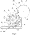
Fig. 5 , the transferringapparatus 2 is adapted to convey and change the stream U1 of the rod-like articles from thefeeding apparatus 300 into the stream U2 of the rod-like articles fed to the receivingapparatus 200. The rod-like articles are in this case filter segments. The stream U1 is formed by thesegment groups 41, whereas thesuccessive segment groups 41 are situated at the distance e from one another. The stream U2 is formed from thesegment groups 41, whereas between thesegment groups 41 the distance e'", smaller than the distance e, is maintained. Thefeeding apparatus 300 is adapted to convey the segments on a circular, generally arched path. The segment groups 41 are situated on thecircumferential surface 44 of thewheel 45 and are conveyed on the path of movement by means of the uniformly spaced lugs 46. The segment groups 41 are fed to the transferringapparatus 1 in thefeeding area 14. The transferringapparatus 1 is provided with the lugs of one kind, namely with the slidable lugs 22 being slidable relative to the guidingsurface 34. During the transferring of thesegment groups 41 in thetransferring apparatus 1, the distance between theadjacent segment groups 41 is reduced from the value e via the values e', e" down to e'" decreasing due to the variation of position of the adjacent slidable lugs 22. The segment groups 41 at the distances e'" are transferred to the receivingapparatus 200 in the receivingarea 15. The receivingapparatus 200 is adapted to convey the segments in the stream U2 on a linear path while keeping the distances e'" between the segment groups 41. The apparatus comprising thefeeding apparatus 300, the transferringapparatus 2 and the receivingapparatus 200 is an apparatus for the conversion of stream configuration of thesegment groups 41 conveyed on an arc with distances for the stream configuration of thesegment groups 41 in the linear movement with smaller distances between the segment groups 41. In the embodiment shown inFig. 5 , the transferringapparatus 2 works with aguide 47 which forms a channel for the transferredsegment groups 41. -
Fig. 6 presents an apparatus for the conversion of stream configuration in a third embodiment comprising thefeeding apparatus 300, the transferringapparatus 3 and the receivingapparatus 200. In the third embodiment, the transferringapparatus 3 is adapted to convert the stream V1 of thesegment groups 41 into the segment stream V2, whereas in the stream V2 there are no distances between the segments. The stream V1 is conveyed on a circular path. In thetransferring apparatus 3, the slidable lugs 26 having a smaller thickness than the slidable lugs 22 in the previous embodiments are used, for example the slidable lugs 26 may be designed as steel plates. The guidingsurface 37 is a cylindrical surface with theaxis 36 situated eccentrically relative to theaxis 21 on which thearms 27 with the slidable lugs 26 are rotatably attached. The guidingsurface 37 may be stationary, then the segments will be conveyed by sliding on the guidingsurface 37. The guidingsurface 37 may be rotational with the axis ofrotation 36, whereas the guidingsurface 37 rotates with a rotational speed equal to the rotational speed of thedrive disc 13. Due to the eccentric situation of the guidingsurface 37, the slidable lugs 26 protrude above the guidingsurface 37 to the height r which varies with the rotation of the slidable lugs 26 around theaxis 21. For theslidable lug 26 being in the receivingarea 15, the height r decreases to zero or to a value close to zero. Due to the fact that the height r drops to zero, it is possible to push thesegment groups 41 close to one another. Pushing thesegment groups 41 close to one another in the stream V2 is also possible when the slidable lugs 26 do not go completely below the guidingsurface 37 while keeping the linear speed of the receivingapparatus 200 smaller than the speed of the slidable lugs 26. Similar to the previous embodiments, thearms 27 are attached on theaxis 21, whereas thedrive disc 13 is attached eccentrically on theaxis 11. Similar to the previous embodiments, during the rotation of the transferringapparatus 3 there occurs a cyclical variation of distances between the adjacent slidable lugs 26, whereas such distance reaches the smallest value for the slidable lugs 26 being at the receivingarea 15. In the course of conveying of thesegment groups 41 in thetransferring apparatus 3, the distance is reduced from the value c as in the stream V1, via the values c', c" and c'" decreasing due to the variation of position of the slidable lugs 26, with the distance c'" being slightly greater than the thickness of the slidable lugs 26, down to the value c"" equal to zero in the receivingapparatus 200. The linear speed of the belt conveyor in the receivingapparatus 200 may be equal to or smaller than the speed with which the slidable lugs 26 move. The configuration of the stream V2 is such that the segments are conveyed coaxially linearly one after another, the segments touching one another. -
Fig. 7 presents an apparatus for the conversion of stream configuration in a fourth embodiment comprising thefeeding apparatus 300, the transferringapparatus 4 and the receivingapparatus 200. In the fourth embodiment, the transferringapparatus 4 is adapted to convert the stream W1 of thesegment groups 41 conveyed at distances s into the stream W2 of segments without distances. In thetransferring apparatus 4, thelugs 26 like in the third embodiment are used, whereas thearms 28 to which the slidable lugs 26 are attached are fixed on a plurality of axes ofrotation 38 arranged around the axis 21.The axes ofrotation 38 may be arranged in thedisc 48 rotatably attached on theaxis 21. The stationary guiding surface 37' is a cylindrical surface or a cylindrical surface sector with theaxis 36 situated eccentrically relative to theaxis 21. The segment groups 41 are conveyed by sliding on the guidingsurface 39. The guidingsurface 39 may have a circumferential cut-out in which the slidable lugs 26 move. Due to the eccentric arrangment of the guidingsurface 39, the slidable lugs 26 protrude above the guidingsurface 39 to a different height varying with the rotation of the slidable lugs 26. Theslidable lug 26 being in the receivingarea 15 does not protrude above the guidingsurface 39. As a result, it is possible to push thesegment groups 41 close to one another. The distances between thesegment groups 41 decrease from the value s of the stream W1 via s' and s" due to a change in mutual position of the slidable lugs 26 down to the value s'" equal to zero. In the stream W1, the segments are conveyed insegment groups 41 on an arc, with the distances s being kept between the groups. The configuration of the stream W2 is such that the segments are conveyed coaxially linearly one after another, the segments abutting. -
Fig. 8 shows an apparatus for the conversion of segment stream configuration comprising thefeeding apparatus 60 to feed thesegment groups 70 or individual segments, the transferringapparatuses apparatus 200. The input stream Z1 of thesegment groups 70 or the individual segments has an input configuration in which thesegment groups 70 or the individual segments are conveyed at defined distances h. The output stream Z5 has an output configuration in which thesegment groups 70 or the individual segments are conveyed at defined distances h'. The transferringapparatuses groups 70 or the segments or keep the distances of the preceding streams. The transferringapparatus apparatus
Claims (14)
- Transferring apparatus (1) for transferring of a stream of rod-like articles (40) from an apparatus (100) feeding rod-like articles to an apparatus (200) receiving the rod-like articles in the machines of the tobacco industry, whereas in the feeding apparatus (100) the rod-like articles (40) are conveyed in a first stream (S1) of rod-like articles in which the rod-like articles are arranged in a first configuration, and in the receiving apparatus (200) the rod-like articles (40) are conveyed in a second stream (S2) of rod-like articles in which the rod-like articles (40) are arranged in a second configuration, comprising:a transferring wheel (30);non-slidable lugs (33) situated on the circumference of the transferring wheel (30);a guiding surface (34) to guide the rod-like article, the rod-like articles being conveyed axially, tangentially to the guiding surface (34);
characterised in thatthe apparatus has a slidable lug (22) being slidable relative to the circumference of the transferring wheel (30) by means of a drive mechanism (10) so that the said slidable lug (22) varies its position relative to an adjacent non-slidable lug (33). - Apparatus as in claim 1 characterised in that the slidable lug (22) is attached to an arm (20) being rotatably attached on the axis of rotation (31) of the transferring wheel (30).
- Apparatus as in claim 1 characterised in that the slidable lug (22) is attached to an arm (20) being attached rotatably eccentrically relative to the axis of rotation (31) of the transferring wheel (30).
- Apparatus as in any of the claims 1 to 3 characterised in that the rotary drive mechanism (10) is rotatably or slidably coupled with the arm (20) of the lug (22) at a coupling point (K), whereas the distance of the coupling point (K) from the axis of rotation (11) of the drive mechanism (10) cyclically varies during rotation of the drive mechanism (10).
- Apparatus as in claim 4 characterised in that the drive mechanism (10) is provided with a drive disc (13) having a guiding groove (12) engaged with a coupling mandrel (23) attached to the arm (20).
- Apparatus as in claim 5 characterised in that the drive disc (13) is attached eccentrically relative to the axis of rotation (31) of the transferring wheel (30).
- Apparatus as in any of the previous claims characterised by having at least two slidable lugs (22) and at least two non-slidable lugs (33) arranged alternately.
- Apparatus as in any of the claims 1 to 7 characterised in that the guiding surface (34) is the circumferential surface of the transferring wheel (30).
- Apparatus as in any of the claims 1 to 7 characterised in that the guiding surface (34) is a cylindrical surface situated above the circumferential surface of the transferring wheel (30).
- Apparatus for the conversion of configuration of a stream of rod-like articles in the machines of the tobacco industry comprising:an apparatus (100) feeding rod-like articles in which a first stream (S1) of rod-like articles is conveyed and from which the rod-like articles (40) are fed to a transferring apparatus (1), whereas the rod-like articles (40) in the first stream (S1) are arranged in a first configuration;a transferring apparatus (1) for transferring of the rod-like articles according to one of the claims 1 to 9, whereas the rod-like articles are transferred to a receiving apparatus (200); anda receiving apparatus (200) for receiving rod-like articles in which a second stream (S2) of rod-like articles is conveyed, whereas the rod-like articles (40) in the second stream (S2) are arranged in a second configuration.
- Apparatus as in claim 10 characterised in that the feeding apparatus (100) is provided with a separating cam (111) designed to feed the rod-like articles and situated in a plane perpendicular to the transferring plane.
- Apparatus as in claim 11 characterised in that the feeding apparatus (100) has a feeding wheel designed to feed the rod-like articles and situated in a plane perpendicular to the transferring plane.
- Apparatus as in any of the claims 10 to 12 characterised in that the feeding apparatus (200) is a belt conveyor.
- Method for transferring of rod-like articles being conveyed axially from an apparatus (100) feeding the rod-like articles to an apparatus (200) receiving the rod-like articles by means of a transferring apparatus (1) provided with a transferring wheel (30) and with lugs (22, 33) whereinthe rod-like articles are fed from the feeding apparatus to the transferring apparatus,the rod-like articles are conveyed in the transferring apparatus, setting input distances between the rod-like articles in the transferring apparatus,the rod-like articles are transferred from the transferring apparatus to the receiving apparatus keeping output distances of the transferring apparatus between the successive rod-like articles,
characterised in thatduring conveying of the rod-like articles in the transferring apparatus the rod-like articles are shifted relative to one another so that the input distances between the rod-like articles are varied to the output distances by changing the relative position of the adjacent lugs in the conveying apparatus, andin that the input distances are uniform, and the output distances are alternately uniform.
Priority Applications (1)
| Application Number | Priority Date | Filing Date | Title |
|---|---|---|---|
| PL18737974.8T PL3629780T5 (en) | 2017-05-29 | 2018-05-22 | Transferring apparatus for transferring and method for transferring of rod-like articles of tobacco industry, and apparatus for conversion of configuration of a stream of such articles |
Applications Claiming Priority (2)
| Application Number | Priority Date | Filing Date | Title |
|---|---|---|---|
| PL421723A PL238818B1 (en) | 2017-05-29 | 2017-05-29 | Transfer device intended for transferring and method for transferring of tobacco industry bar-like articles and the device for conversion of such articles stream configuration |
| PCT/IB2018/053595 WO2018220472A1 (en) | 2017-05-29 | 2018-05-22 | Transferring apparatus for transferring and method for transferring of rod-like articles of tobacco industry, and apparatus for conversion of configuration of a stream of such articles |
Publications (3)
| Publication Number | Publication Date |
|---|---|
| EP3629780A1 EP3629780A1 (en) | 2020-04-08 |
| EP3629780B1 EP3629780B1 (en) | 2020-09-23 |
| EP3629780B2 true EP3629780B2 (en) | 2025-03-19 |
Family
ID=64454474
Family Applications (1)
| Application Number | Title | Priority Date | Filing Date |
|---|---|---|---|
| EP18737974.8A Active EP3629780B2 (en) | 2017-05-29 | 2018-05-22 | Transferring apparatus for transferring and method for transferring of rod-like articles of tobacco industry, and apparatus for conversion of configuration of a stream of such articles |
Country Status (8)
| Country | Link |
|---|---|
| US (1) | US11213065B2 (en) |
| EP (1) | EP3629780B2 (en) |
| JP (1) | JP7158418B2 (en) |
| KR (1) | KR102614518B1 (en) |
| CN (1) | CN110650638B (en) |
| PL (2) | PL238818B1 (en) |
| RU (1) | RU2754167C2 (en) |
| WO (1) | WO2018220472A1 (en) |
Families Citing this family (2)
| Publication number | Priority date | Publication date | Assignee | Title |
|---|---|---|---|---|
| CN121620304A (en) * | 2023-08-08 | 2026-03-06 | 菲利普莫里斯生产公司 | The segments for aerosol-generated products are positioned using positioning wheels with adjustable receiving positions. |
| CN118141148A (en) * | 2024-01-23 | 2024-06-07 | 许昌烟草机械有限责任公司 | A conveying device for rod-shaped materials |
Citations (1)
| Publication number | Priority date | Publication date | Assignee | Title |
|---|---|---|---|---|
| WO2010076653A1 (en) † | 2008-12-30 | 2010-07-08 | Philip Morris Products S.A. | Apparatus and method for combining components for smoking articles |
Family Cites Families (21)
| Publication number | Priority date | Publication date | Assignee | Title |
|---|---|---|---|---|
| GB915203A (en) * | 1958-02-27 | 1963-01-09 | Desmond Walter Molins | Improvements in or relating to the manufacture of composite mouthpieces for cigarettes |
| GB1053547A (en) | 1962-09-05 | |||
| US3357320A (en) | 1965-02-05 | 1967-12-12 | Brown & Williamson Tobacco Corp | Multiple filter assembly apparatus |
| US4063480A (en) * | 1976-04-30 | 1977-12-20 | Hauni-Werke Korber & Co., Kg | Apparatus for severing rod-shaped smokers' products |
| GB1578737A (en) | 1976-07-22 | 1980-11-05 | Molins Ltd | Apparatus for assembling rod-like articles |
| IT1188972B (en) | 1980-12-12 | 1988-01-28 | Gd Spa | TRANSFER DEVICE FOR BAR-SHAPED ITEMS |
| IT1186915B (en) * | 1985-07-24 | 1987-12-16 | Sasib Spa | HONEY DRUM DEVICE FOR THE COLLECTION OF ASTIFORM OBJECTS FROM A POWER SUPPLY |
| ES2013098A6 (en) | 1989-03-10 | 1990-04-16 | Jofemar Sa | UNITARY PRODUCT EXTRACTOR. |
| ITBO20040239A1 (en) | 2004-04-22 | 2004-07-22 | Gd Spa | TRANSFER UNIT OF ELONGATED ITEMS |
| WO2006004111A1 (en) | 2004-07-07 | 2006-01-12 | Japan Tobacco Inc. | Filter rod manufacturing machine |
| PL383995A1 (en) | 2007-12-10 | 2009-06-22 | Philip Morris Products S.A. | The manner of setting up a group of segments in multi-segment filter production process and a device for preparation and setting up in groups of segments in multi-segment filter production process |
| DE102008063847B4 (en) * | 2008-12-19 | 2010-08-05 | Hauni Maschinenbau Ag | Swash plate, conveyor drum and machine of the tobacco processing industry |
| PL388549A1 (en) * | 2009-07-15 | 2011-01-17 | International Tobacco Machinery Poland Spółka Z Ograniczoną Odpowiedzialnością | Method for secure transmission of filter elements in the manufacturing process of multi-segment filters |
| ITBO20110158A1 (en) * | 2011-03-28 | 2012-09-29 | Gd Spa | TRANSFER OR ACCOMPANIMENT DRUM FOR FILTER OR CIGARETTE CUTTERS WITH OPERATIONAL HEADS CARRIED BY RADIAL ARMS. |
| BR112013032904B1 (en) | 2011-06-20 | 2021-01-05 | Philip Morris Products S.A. | apparatus and method for introducing objects into a continuous flow of material |
| CN103010776B (en) * | 2012-12-14 | 2015-01-07 | 湖北中烟工业有限责任公司 | Capsule filling mechanism for producing capsule filter rods |
| CN103144953B (en) * | 2013-03-20 | 2015-02-25 | 湖南大学 | Bar stock axial-radial high-speed flexible conveying device and conveying method |
| US10085479B2 (en) * | 2014-03-07 | 2018-10-02 | Aiger Group Ag | Apparatus, method and system for buffering and processing multi-segment rod-like articles |
| EP3050441A1 (en) * | 2015-01-29 | 2016-08-03 | International Tobacco Machinery Poland Sp. z o.o. | Apparatus to manufacture rod-like articles used in products of the tobacco industry and transport unit to transfer stream of rod-like articles |
| CN106347982B (en) * | 2015-07-13 | 2018-10-02 | 中烟机械技术中心有限责任公司 | By rod-shaped products by transform linear motion be circular motion transfer device and method |
| HUE034707T2 (en) | 2015-07-16 | 2018-02-28 | Int Tobacco Machinery Poland Sp Zoo | A transfer disc and its use |
-
2017
- 2017-05-29 PL PL421723A patent/PL238818B1/en unknown
-
2018
- 2018-05-22 CN CN201880033370.1A patent/CN110650638B/en active Active
- 2018-05-22 WO PCT/IB2018/053595 patent/WO2018220472A1/en not_active Ceased
- 2018-05-22 KR KR1020197035119A patent/KR102614518B1/en active Active
- 2018-05-22 PL PL18737974.8T patent/PL3629780T5/en unknown
- 2018-05-22 EP EP18737974.8A patent/EP3629780B2/en active Active
- 2018-05-22 RU RU2019138223A patent/RU2754167C2/en active
- 2018-05-22 US US16/609,452 patent/US11213065B2/en not_active Expired - Fee Related
- 2018-05-22 JP JP2019565916A patent/JP7158418B2/en active Active
Patent Citations (1)
| Publication number | Priority date | Publication date | Assignee | Title |
|---|---|---|---|---|
| WO2010076653A1 (en) † | 2008-12-30 | 2010-07-08 | Philip Morris Products S.A. | Apparatus and method for combining components for smoking articles |
Also Published As
| Publication number | Publication date |
|---|---|
| RU2019138223A3 (en) | 2021-08-02 |
| WO2018220472A1 (en) | 2018-12-06 |
| EP3629780B1 (en) | 2020-09-23 |
| PL421723A1 (en) | 2018-12-03 |
| US20200163374A1 (en) | 2020-05-28 |
| JP2020521482A (en) | 2020-07-27 |
| JP7158418B2 (en) | 2022-10-21 |
| EP3629780A1 (en) | 2020-04-08 |
| PL3629780T5 (en) | 2025-06-09 |
| KR102614518B1 (en) | 2023-12-14 |
| RU2019138223A (en) | 2021-06-30 |
| BR112019025252A2 (en) | 2020-06-23 |
| KR20200014302A (en) | 2020-02-10 |
| CN110650638A (en) | 2020-01-03 |
| RU2754167C2 (en) | 2021-08-30 |
| US11213065B2 (en) | 2022-01-04 |
| PL3629780T3 (en) | 2021-01-25 |
| CN110650638B (en) | 2021-12-07 |
| PL238818B1 (en) | 2021-10-11 |
Similar Documents
| Publication | Publication Date | Title |
|---|---|---|
| RU2710767C2 (en) | Apparatus for making multi-segment rods for tobacco industry products and conveyor unit for transferring sequence of rod-like elements | |
| EP3285604B1 (en) | Apparatus for centring of a rod-like article or a rod-like article group | |
| EP3629780B1 (en) | Transferring apparatus for transferring and method for transferring of rod-like articles of tobacco industry, and apparatus for conversion of configuration of a stream of such articles | |
| EP3322309B1 (en) | Method and apparatus for shifting of rod-like articles, and apparatus of shifting of rod-like articles | |
| EP3376883A1 (en) | Centering device for rod shaped articles of the tobacco industry | |
| EP3158879B1 (en) | Transfer method and transferring apparatus for transferring rod-shaped article | |
| US11219238B2 (en) | Method and apparatus for conveying rod-like articles of tobacco industry | |
| BR112019025252B1 (en) | TRANSFER APPARATUS FOR TRANSFERRING A CHAIN OF ROD-LIKE ARTICLES FROM AN APPARATUS FEEDING ROD-LIKE ARTICLES TO AN APPARATUS RECEIVING THE ROD-LIKE ARTICLES IN TOBACCO INDUSTRY MACHINES, APPARATUS FOR CONVERTING A CHAIN OF ROD-LIKE ARTICLES IN TOBACCO INDUSTRY MACHINES AND METHOD FOR TRANSFERRING A ROD-LIKE ARTICLE FROM AN APPARATUS FEEDING THE ROD-LIKE ARTICLE TO AN APPARATUS RECEIVING THE ROD-LIKE ARTICLE BY MEANS OF A TRANSFER APPARATUS PROVIDED WITH A TRANSFER WHEEL AND WITH PROTRUSIONS | |
| US20260114499A1 (en) | Conveying and forming method and apparatus for forming a stream of tobacco industry segments | |
| EP4378327A1 (en) | Apparatus for manufacturing multi-segment articles | |
| EP4487701B1 (en) | Conveying and forming method and apparatus for forming a stream of tobacco industry segments | |
| EP3501302A1 (en) | Apparatus for manufacturing multi-segment rods of the tobacco processing industry | |
| WO2024246676A1 (en) | Apparatus for pushing together rod-like articles of tobacco industry | |
| CN120265152A (en) | Apparatus and method for manufacturing multi-segment articles |
Legal Events
| Date | Code | Title | Description |
|---|---|---|---|
| STAA | Information on the status of an ep patent application or granted ep patent |
Free format text: STATUS: UNKNOWN |
|
| STAA | Information on the status of an ep patent application or granted ep patent |
Free format text: STATUS: THE INTERNATIONAL PUBLICATION HAS BEEN MADE |
|
| PUAI | Public reference made under article 153(3) epc to a published international application that has entered the european phase |
Free format text: ORIGINAL CODE: 0009012 |
|
| STAA | Information on the status of an ep patent application or granted ep patent |
Free format text: STATUS: REQUEST FOR EXAMINATION WAS MADE |
|
| 17P | Request for examination filed |
Effective date: 20191223 |
|
| AK | Designated contracting states |
Kind code of ref document: A1 Designated state(s): AL AT BE BG CH CY CZ DE DK EE ES FI FR GB GR HR HU IE IS IT LI LT LU LV MC MK MT NL NO PL PT RO RS SE SI SK SM TR |
|
| AX | Request for extension of the european patent |
Extension state: BA ME |
|
| GRAP | Despatch of communication of intention to grant a patent |
Free format text: ORIGINAL CODE: EPIDOSNIGR1 |
|
| STAA | Information on the status of an ep patent application or granted ep patent |
Free format text: STATUS: GRANT OF PATENT IS INTENDED |
|
| INTG | Intention to grant announced |
Effective date: 20200717 |
|
| GRAS | Grant fee paid |
Free format text: ORIGINAL CODE: EPIDOSNIGR3 |
|
| GRAA | (expected) grant |
Free format text: ORIGINAL CODE: 0009210 |
|
| STAA | Information on the status of an ep patent application or granted ep patent |
Free format text: STATUS: THE PATENT HAS BEEN GRANTED |
|
| DAV | Request for validation of the european patent (deleted) | ||
| DAX | Request for extension of the european patent (deleted) | ||
| AK | Designated contracting states |
Kind code of ref document: B1 Designated state(s): AL AT BE BG CH CY CZ DE DK EE ES FI FR GB GR HR HU IE IS IT LI LT LU LV MC MK MT NL NO PL PT RO RS SE SI SK SM TR |
|
| REG | Reference to a national code |
Ref country code: GB Ref legal event code: FG4D |
|
| REG | Reference to a national code |
Ref country code: CH Ref legal event code: EP |
|
| REG | Reference to a national code |
Ref country code: IE Ref legal event code: FG4D |
|
| REG | Reference to a national code |
Ref country code: DE Ref legal event code: R096 Ref document number: 602018008128 Country of ref document: DE Ref country code: AT Ref legal event code: REF Ref document number: 1315465 Country of ref document: AT Kind code of ref document: T Effective date: 20201015 |
|
| REG | Reference to a national code |
Ref country code: CH Ref legal event code: NV Representative=s name: VALIPAT S.A. C/O BOVARD SA NEUCHATEL, CH |
|
| PG25 | Lapsed in a contracting state [announced via postgrant information from national office to epo] |
Ref country code: HR Free format text: LAPSE BECAUSE OF FAILURE TO SUBMIT A TRANSLATION OF THE DESCRIPTION OR TO PAY THE FEE WITHIN THE PRESCRIBED TIME-LIMIT Effective date: 20200923 Ref country code: GR Free format text: LAPSE BECAUSE OF FAILURE TO SUBMIT A TRANSLATION OF THE DESCRIPTION OR TO PAY THE FEE WITHIN THE PRESCRIBED TIME-LIMIT Effective date: 20201224 Ref country code: NO Free format text: LAPSE BECAUSE OF FAILURE TO SUBMIT A TRANSLATION OF THE DESCRIPTION OR TO PAY THE FEE WITHIN THE PRESCRIBED TIME-LIMIT Effective date: 20201223 Ref country code: FI Free format text: LAPSE BECAUSE OF FAILURE TO SUBMIT A TRANSLATION OF THE DESCRIPTION OR TO PAY THE FEE WITHIN THE PRESCRIBED TIME-LIMIT Effective date: 20200923 Ref country code: SE Free format text: LAPSE BECAUSE OF FAILURE TO SUBMIT A TRANSLATION OF THE DESCRIPTION OR TO PAY THE FEE WITHIN THE PRESCRIBED TIME-LIMIT Effective date: 20200923 |
|
| REG | Reference to a national code |
Ref country code: AT Ref legal event code: MK05 Ref document number: 1315465 Country of ref document: AT Kind code of ref document: T Effective date: 20200923 |
|
| PG25 | Lapsed in a contracting state [announced via postgrant information from national office to epo] |
Ref country code: RS Free format text: LAPSE BECAUSE OF FAILURE TO SUBMIT A TRANSLATION OF THE DESCRIPTION OR TO PAY THE FEE WITHIN THE PRESCRIBED TIME-LIMIT Effective date: 20200923 Ref country code: LV Free format text: LAPSE BECAUSE OF FAILURE TO SUBMIT A TRANSLATION OF THE DESCRIPTION OR TO PAY THE FEE WITHIN THE PRESCRIBED TIME-LIMIT Effective date: 20200923 |
|
| REG | Reference to a national code |
Ref country code: NL Ref legal event code: MP Effective date: 20200923 |
|
| REG | Reference to a national code |
Ref country code: LT Ref legal event code: MG4D |
|
| PG25 | Lapsed in a contracting state [announced via postgrant information from national office to epo] |
Ref country code: SM Free format text: LAPSE BECAUSE OF FAILURE TO SUBMIT A TRANSLATION OF THE DESCRIPTION OR TO PAY THE FEE WITHIN THE PRESCRIBED TIME-LIMIT Effective date: 20200923 Ref country code: LT Free format text: LAPSE BECAUSE OF FAILURE TO SUBMIT A TRANSLATION OF THE DESCRIPTION OR TO PAY THE FEE WITHIN THE PRESCRIBED TIME-LIMIT Effective date: 20200923 Ref country code: EE Free format text: LAPSE BECAUSE OF FAILURE TO SUBMIT A TRANSLATION OF THE DESCRIPTION OR TO PAY THE FEE WITHIN THE PRESCRIBED TIME-LIMIT Effective date: 20200923 Ref country code: CZ Free format text: LAPSE BECAUSE OF FAILURE TO SUBMIT A TRANSLATION OF THE DESCRIPTION OR TO PAY THE FEE WITHIN THE PRESCRIBED TIME-LIMIT Effective date: 20200923 Ref country code: PT Free format text: LAPSE BECAUSE OF FAILURE TO SUBMIT A TRANSLATION OF THE DESCRIPTION OR TO PAY THE FEE WITHIN THE PRESCRIBED TIME-LIMIT Effective date: 20210125 Ref country code: RO Free format text: LAPSE BECAUSE OF FAILURE TO SUBMIT A TRANSLATION OF THE DESCRIPTION OR TO PAY THE FEE WITHIN THE PRESCRIBED TIME-LIMIT Effective date: 20200923 |
|
| PG25 | Lapsed in a contracting state [announced via postgrant information from national office to epo] |
Ref country code: AL Free format text: LAPSE BECAUSE OF FAILURE TO SUBMIT A TRANSLATION OF THE DESCRIPTION OR TO PAY THE FEE WITHIN THE PRESCRIBED TIME-LIMIT Effective date: 20200923 Ref country code: AT Free format text: LAPSE BECAUSE OF FAILURE TO SUBMIT A TRANSLATION OF THE DESCRIPTION OR TO PAY THE FEE WITHIN THE PRESCRIBED TIME-LIMIT Effective date: 20200923 Ref country code: ES Free format text: LAPSE BECAUSE OF FAILURE TO SUBMIT A TRANSLATION OF THE DESCRIPTION OR TO PAY THE FEE WITHIN THE PRESCRIBED TIME-LIMIT Effective date: 20200923 Ref country code: IS Free format text: LAPSE BECAUSE OF FAILURE TO SUBMIT A TRANSLATION OF THE DESCRIPTION OR TO PAY THE FEE WITHIN THE PRESCRIBED TIME-LIMIT Effective date: 20210123 |
|
| REG | Reference to a national code |
Ref country code: DE Ref legal event code: R026 Ref document number: 602018008128 Country of ref document: DE |
|
| PLBI | Opposition filed |
Free format text: ORIGINAL CODE: 0009260 |
|
| PG25 | Lapsed in a contracting state [announced via postgrant information from national office to epo] |
Ref country code: SK Free format text: LAPSE BECAUSE OF FAILURE TO SUBMIT A TRANSLATION OF THE DESCRIPTION OR TO PAY THE FEE WITHIN THE PRESCRIBED TIME-LIMIT Effective date: 20200923 |
|
| PLAX | Notice of opposition and request to file observation + time limit sent |
Free format text: ORIGINAL CODE: EPIDOSNOBS2 |
|
| 26 | Opposition filed |
Opponent name: G.D S.P.A. Effective date: 20210622 |
|
| PG25 | Lapsed in a contracting state [announced via postgrant information from national office to epo] |
Ref country code: DK Free format text: LAPSE BECAUSE OF FAILURE TO SUBMIT A TRANSLATION OF THE DESCRIPTION OR TO PAY THE FEE WITHIN THE PRESCRIBED TIME-LIMIT Effective date: 20200923 |
|
| PLBB | Reply of patent proprietor to notice(s) of opposition received |
Free format text: ORIGINAL CODE: EPIDOSNOBS3 |
|
| PG25 | Lapsed in a contracting state [announced via postgrant information from national office to epo] |
Ref country code: LU Free format text: LAPSE BECAUSE OF NON-PAYMENT OF DUE FEES Effective date: 20210522 Ref country code: MC Free format text: LAPSE BECAUSE OF FAILURE TO SUBMIT A TRANSLATION OF THE DESCRIPTION OR TO PAY THE FEE WITHIN THE PRESCRIBED TIME-LIMIT Effective date: 20200923 |
|
| REG | Reference to a national code |
Ref country code: BE Ref legal event code: MM Effective date: 20210531 |
|
| PG25 | Lapsed in a contracting state [announced via postgrant information from national office to epo] |
Ref country code: IE Free format text: LAPSE BECAUSE OF NON-PAYMENT OF DUE FEES Effective date: 20210522 |
|
| PG25 | Lapsed in a contracting state [announced via postgrant information from national office to epo] |
Ref country code: FR Free format text: LAPSE BECAUSE OF NON-PAYMENT OF DUE FEES Effective date: 20210531 |
|
| PG25 | Lapsed in a contracting state [announced via postgrant information from national office to epo] |
Ref country code: BE Free format text: LAPSE BECAUSE OF NON-PAYMENT OF DUE FEES Effective date: 20210531 |
|
| APBM | Appeal reference recorded |
Free format text: ORIGINAL CODE: EPIDOSNREFNO |
|
| APBP | Date of receipt of notice of appeal recorded |
Free format text: ORIGINAL CODE: EPIDOSNNOA2O |
|
| APAH | Appeal reference modified |
Free format text: ORIGINAL CODE: EPIDOSCREFNO |
|
| APBQ | Date of receipt of statement of grounds of appeal recorded |
Free format text: ORIGINAL CODE: EPIDOSNNOA3O |
|
| P01 | Opt-out of the competence of the unified patent court (upc) registered |
Effective date: 20230418 |
|
| PG25 | Lapsed in a contracting state [announced via postgrant information from national office to epo] |
Ref country code: NL Free format text: LAPSE BECAUSE OF NON-PAYMENT OF DUE FEES Effective date: 20200923 Ref country code: CY Free format text: LAPSE BECAUSE OF FAILURE TO SUBMIT A TRANSLATION OF THE DESCRIPTION OR TO PAY THE FEE WITHIN THE PRESCRIBED TIME-LIMIT Effective date: 20200923 |
|
| PG25 | Lapsed in a contracting state [announced via postgrant information from national office to epo] |
Ref country code: HU Free format text: LAPSE BECAUSE OF FAILURE TO SUBMIT A TRANSLATION OF THE DESCRIPTION OR TO PAY THE FEE WITHIN THE PRESCRIBED TIME-LIMIT; INVALID AB INITIO Effective date: 20180522 |
|
| PG25 | Lapsed in a contracting state [announced via postgrant information from national office to epo] |
Ref country code: SI Free format text: LAPSE BECAUSE OF FAILURE TO SUBMIT A TRANSLATION OF THE DESCRIPTION OR TO PAY THE FEE WITHIN THE PRESCRIBED TIME-LIMIT Effective date: 20200923 |
|
| PGFP | Annual fee paid to national office [announced via postgrant information from national office to epo] |
Ref country code: GB Payment date: 20230524 Year of fee payment: 6 |
|
| PG25 | Lapsed in a contracting state [announced via postgrant information from national office to epo] |
Ref country code: MK Free format text: LAPSE BECAUSE OF FAILURE TO SUBMIT A TRANSLATION OF THE DESCRIPTION OR TO PAY THE FEE WITHIN THE PRESCRIBED TIME-LIMIT Effective date: 20200923 |
|
| APAH | Appeal reference modified |
Free format text: ORIGINAL CODE: EPIDOSCREFNO |
|
| PG25 | Lapsed in a contracting state [announced via postgrant information from national office to epo] |
Ref country code: TR Free format text: LAPSE BECAUSE OF FAILURE TO SUBMIT A TRANSLATION OF THE DESCRIPTION OR TO PAY THE FEE WITHIN THE PRESCRIBED TIME-LIMIT Effective date: 20200923 |
|
| PG25 | Lapsed in a contracting state [announced via postgrant information from national office to epo] |
Ref country code: MT Free format text: LAPSE BECAUSE OF FAILURE TO SUBMIT A TRANSLATION OF THE DESCRIPTION OR TO PAY THE FEE WITHIN THE PRESCRIBED TIME-LIMIT Effective date: 20200923 |
|
| APBU | Appeal procedure closed |
Free format text: ORIGINAL CODE: EPIDOSNNOA9O |
|
| GBPC | Gb: european patent ceased through non-payment of renewal fee |
Effective date: 20240522 |
|
| PUAH | Patent maintained in amended form |
Free format text: ORIGINAL CODE: 0009272 |
|
| STAA | Information on the status of an ep patent application or granted ep patent |
Free format text: STATUS: PATENT MAINTAINED AS AMENDED |
|
| 27A | Patent maintained in amended form |
Effective date: 20250319 |
|
| AK | Designated contracting states |
Kind code of ref document: B2 Designated state(s): AL AT BE BG CH CY CZ DE DK EE ES FI FR GB GR HR HU IE IS IT LI LT LU LV MC MK MT NL NO PL PT RO RS SE SI SK SM TR |
|
| REG | Reference to a national code |
Ref country code: DE Ref legal event code: R102 Ref document number: 602018008128 Country of ref document: DE |
|
| PG25 | Lapsed in a contracting state [announced via postgrant information from national office to epo] |
Ref country code: GB Free format text: LAPSE BECAUSE OF NON-PAYMENT OF DUE FEES Effective date: 20240522 |
|
| PGFP | Annual fee paid to national office [announced via postgrant information from national office to epo] |
Ref country code: PL Payment date: 20250508 Year of fee payment: 8 Ref country code: DE Payment date: 20250521 Year of fee payment: 8 |
|
| PGFP | Annual fee paid to national office [announced via postgrant information from national office to epo] |
Ref country code: IT Payment date: 20250527 Year of fee payment: 8 |
|
| PGFP | Annual fee paid to national office [announced via postgrant information from national office to epo] |
Ref country code: BG Payment date: 20250521 Year of fee payment: 8 |
|
| PGFP | Annual fee paid to national office [announced via postgrant information from national office to epo] |
Ref country code: CH Payment date: 20250601 Year of fee payment: 8 |