EP3629675A1 - Object sensor including deposited heater - Google Patents
Object sensor including deposited heater Download PDFInfo
- Publication number
- EP3629675A1 EP3629675A1 EP19196846.0A EP19196846A EP3629675A1 EP 3629675 A1 EP3629675 A1 EP 3629675A1 EP 19196846 A EP19196846 A EP 19196846A EP 3629675 A1 EP3629675 A1 EP 3629675A1
- Authority
- EP
- European Patent Office
- Prior art keywords
- cover
- layers
- heater
- electrically conductive
- conductive material
- Prior art date
- Legal status (The legal status is an assumption and is not a legal conclusion. Google has not performed a legal analysis and makes no representation as to the accuracy of the status listed.)
- Granted
Links
Images
Classifications
-
- H—ELECTRICITY
- H05—ELECTRIC TECHNIQUES NOT OTHERWISE PROVIDED FOR
- H05K—PRINTED CIRCUITS; CASINGS OR CONSTRUCTIONAL DETAILS OF ELECTRIC APPARATUS; MANUFACTURE OF ASSEMBLAGES OF ELECTRICAL COMPONENTS
- H05K3/00—Apparatus or processes for manufacturing printed circuits
- H05K3/10—Apparatus or processes for manufacturing printed circuits in which conductive material is applied to the insulating support in such a manner as to form the desired conductive pattern
- H05K3/12—Apparatus or processes for manufacturing printed circuits in which conductive material is applied to the insulating support in such a manner as to form the desired conductive pattern using thick film techniques, e.g. printing techniques to apply the conductive material or similar techniques for applying conductive paste or ink patterns
- H05K3/1216—Apparatus or processes for manufacturing printed circuits in which conductive material is applied to the insulating support in such a manner as to form the desired conductive pattern using thick film techniques, e.g. printing techniques to apply the conductive material or similar techniques for applying conductive paste or ink patterns by screen printing or stencil printing
-
- G—PHYSICS
- G01—MEASURING; TESTING
- G01S—RADIO DIRECTION-FINDING; RADIO NAVIGATION; DETERMINING DISTANCE OR VELOCITY BY USE OF RADIO WAVES; LOCATING OR PRESENCE-DETECTING BY USE OF THE REFLECTION OR RERADIATION OF RADIO WAVES; ANALOGOUS ARRANGEMENTS USING OTHER WAVES
- G01S7/00—Details of systems according to groups G01S13/00, G01S15/00, G01S17/00
- G01S7/02—Details of systems according to groups G01S13/00, G01S15/00, G01S17/00 of systems according to group G01S13/00
- G01S7/40—Means for monitoring or calibrating
- G01S7/4004—Means for monitoring or calibrating of parts of a radar system
-
- H—ELECTRICITY
- H05—ELECTRIC TECHNIQUES NOT OTHERWISE PROVIDED FOR
- H05B—ELECTRIC HEATING; ELECTRIC LIGHT SOURCES NOT OTHERWISE PROVIDED FOR; CIRCUIT ARRANGEMENTS FOR ELECTRIC LIGHT SOURCES, IN GENERAL
- H05B3/00—Ohmic-resistance heating
- H05B3/84—Heating arrangements specially adapted for transparent or reflecting areas, e.g. for demisting or de-icing windows, mirrors or vehicle windshields
-
- B—PERFORMING OPERATIONS; TRANSPORTING
- B41—PRINTING; LINING MACHINES; TYPEWRITERS; STAMPS
- B41M—PRINTING, DUPLICATING, MARKING, OR COPYING PROCESSES; COLOUR PRINTING
- B41M1/00—Inking and printing with a printer's forme
- B41M1/12—Stencil printing; Silk-screen printing
-
- C—CHEMISTRY; METALLURGY
- C03—GLASS; MINERAL OR SLAG WOOL
- C03C—CHEMICAL COMPOSITION OF GLASSES, GLAZES OR VITREOUS ENAMELS; SURFACE TREATMENT OF GLASS; SURFACE TREATMENT OF FIBRES OR FILAMENTS MADE FROM GLASS, MINERALS OR SLAGS; JOINING GLASS TO GLASS OR OTHER MATERIALS
- C03C17/00—Surface treatment of glass, not in the form of fibres or filaments, by coating
- C03C17/006—Surface treatment of glass, not in the form of fibres or filaments, by coating with materials of composite character
- C03C17/008—Surface treatment of glass, not in the form of fibres or filaments, by coating with materials of composite character comprising a mixture of materials covered by two or more of the groups C03C17/02, C03C17/06, C03C17/22 and C03C17/28
- C03C17/009—Mixtures of organic and inorganic materials, e.g. ormosils and ormocers
-
- C—CHEMISTRY; METALLURGY
- C03—GLASS; MINERAL OR SLAG WOOL
- C03C—CHEMICAL COMPOSITION OF GLASSES, GLAZES OR VITREOUS ENAMELS; SURFACE TREATMENT OF GLASS; SURFACE TREATMENT OF FIBRES OR FILAMENTS MADE FROM GLASS, MINERALS OR SLAGS; JOINING GLASS TO GLASS OR OTHER MATERIALS
- C03C17/00—Surface treatment of glass, not in the form of fibres or filaments, by coating
- C03C17/34—Surface treatment of glass, not in the form of fibres or filaments, by coating with at least two coatings having different compositions
-
- C—CHEMISTRY; METALLURGY
- C09—DYES; PAINTS; POLISHES; NATURAL RESINS; ADHESIVES; COMPOSITIONS NOT OTHERWISE PROVIDED FOR; APPLICATIONS OF MATERIALS NOT OTHERWISE PROVIDED FOR
- C09D—COATING COMPOSITIONS, e.g. PAINTS, VARNISHES OR LACQUERS; FILLING PASTES; CHEMICAL PAINT OR INK REMOVERS; INKS; CORRECTING FLUIDS; WOODSTAINS; PASTES OR SOLIDS FOR COLOURING OR PRINTING; USE OF MATERIALS THEREFOR
- C09D11/00—Inks
- C09D11/52—Electrically conductive inks
-
- G—PHYSICS
- G01—MEASURING; TESTING
- G01S—RADIO DIRECTION-FINDING; RADIO NAVIGATION; DETERMINING DISTANCE OR VELOCITY BY USE OF RADIO WAVES; LOCATING OR PRESENCE-DETECTING BY USE OF THE REFLECTION OR RERADIATION OF RADIO WAVES; ANALOGOUS ARRANGEMENTS USING OTHER WAVES
- G01S13/00—Systems using the reflection or reradiation of radio waves, e.g. radar systems; Analogous systems using reflection or reradiation of waves whose nature or wavelength is irrelevant or unspecified
- G01S13/88—Radar or analogous systems specially adapted for specific applications
- G01S13/93—Radar or analogous systems specially adapted for specific applications for anti-collision purposes
- G01S13/931—Radar or analogous systems specially adapted for specific applications for anti-collision purposes of land vehicles
-
- G—PHYSICS
- G01—MEASURING; TESTING
- G01S—RADIO DIRECTION-FINDING; RADIO NAVIGATION; DETERMINING DISTANCE OR VELOCITY BY USE OF RADIO WAVES; LOCATING OR PRESENCE-DETECTING BY USE OF THE REFLECTION OR RERADIATION OF RADIO WAVES; ANALOGOUS ARRANGEMENTS USING OTHER WAVES
- G01S7/00—Details of systems according to groups G01S13/00, G01S15/00, G01S17/00
- G01S7/02—Details of systems according to groups G01S13/00, G01S15/00, G01S17/00 of systems according to group G01S13/00
-
- G—PHYSICS
- G01—MEASURING; TESTING
- G01S—RADIO DIRECTION-FINDING; RADIO NAVIGATION; DETERMINING DISTANCE OR VELOCITY BY USE OF RADIO WAVES; LOCATING OR PRESENCE-DETECTING BY USE OF THE REFLECTION OR RERADIATION OF RADIO WAVES; ANALOGOUS ARRANGEMENTS USING OTHER WAVES
- G01S7/00—Details of systems according to groups G01S13/00, G01S15/00, G01S17/00
- G01S7/02—Details of systems according to groups G01S13/00, G01S15/00, G01S17/00 of systems according to group G01S13/00
- G01S7/40—Means for monitoring or calibrating
- G01S7/4004—Means for monitoring or calibrating of parts of a radar system
- G01S7/4039—Means for monitoring or calibrating of parts of a radar system of sensor or antenna obstruction, e.g. dirt- or ice-coating
- G01S7/4043—Means for monitoring or calibrating of parts of a radar system of sensor or antenna obstruction, e.g. dirt- or ice-coating including means to prevent or remove the obstruction
-
- G—PHYSICS
- G01—MEASURING; TESTING
- G01S—RADIO DIRECTION-FINDING; RADIO NAVIGATION; DETERMINING DISTANCE OR VELOCITY BY USE OF RADIO WAVES; LOCATING OR PRESENCE-DETECTING BY USE OF THE REFLECTION OR RERADIATION OF RADIO WAVES; ANALOGOUS ARRANGEMENTS USING OTHER WAVES
- G01S7/00—Details of systems according to groups G01S13/00, G01S15/00, G01S17/00
- G01S7/48—Details of systems according to groups G01S13/00, G01S15/00, G01S17/00 of systems according to group G01S17/00
- G01S7/481—Constructional features, e.g. arrangements of optical elements
-
- G—PHYSICS
- G01—MEASURING; TESTING
- G01S—RADIO DIRECTION-FINDING; RADIO NAVIGATION; DETERMINING DISTANCE OR VELOCITY BY USE OF RADIO WAVES; LOCATING OR PRESENCE-DETECTING BY USE OF THE REFLECTION OR RERADIATION OF RADIO WAVES; ANALOGOUS ARRANGEMENTS USING OTHER WAVES
- G01S7/00—Details of systems according to groups G01S13/00, G01S15/00, G01S17/00
- G01S7/48—Details of systems according to groups G01S13/00, G01S15/00, G01S17/00 of systems according to group G01S17/00
- G01S7/497—Means for monitoring or calibrating
-
- H—ELECTRICITY
- H01—ELECTRIC ELEMENTS
- H01B—CABLES; CONDUCTORS; INSULATORS; SELECTION OF MATERIALS FOR THEIR CONDUCTIVE, INSULATING OR DIELECTRIC PROPERTIES
- H01B1/00—Conductors or conductive bodies characterised by the conductive materials; Selection of materials as conductors
- H01B1/20—Conductive material dispersed in non-conductive organic material
- H01B1/22—Conductive material dispersed in non-conductive organic material the conductive material comprising metals or alloys
-
- H—ELECTRICITY
- H05—ELECTRIC TECHNIQUES NOT OTHERWISE PROVIDED FOR
- H05B—ELECTRIC HEATING; ELECTRIC LIGHT SOURCES NOT OTHERWISE PROVIDED FOR; CIRCUIT ARRANGEMENTS FOR ELECTRIC LIGHT SOURCES, IN GENERAL
- H05B3/00—Ohmic-resistance heating
- H05B3/10—Heating elements characterised by the composition or nature of the materials or by the arrangement of the conductor
- H05B3/12—Heating elements characterised by the composition or nature of the materials or by the arrangement of the conductor characterised by the composition or nature of the conductive material
-
- H—ELECTRICITY
- H05—ELECTRIC TECHNIQUES NOT OTHERWISE PROVIDED FOR
- H05B—ELECTRIC HEATING; ELECTRIC LIGHT SOURCES NOT OTHERWISE PROVIDED FOR; CIRCUIT ARRANGEMENTS FOR ELECTRIC LIGHT SOURCES, IN GENERAL
- H05B3/00—Ohmic-resistance heating
- H05B3/10—Heating elements characterised by the composition or nature of the materials or by the arrangement of the conductor
- H05B3/18—Heating elements characterised by the composition or nature of the materials or by the arrangement of the conductor the conductor being embedded in an insulating material
-
- H—ELECTRICITY
- H05—ELECTRIC TECHNIQUES NOT OTHERWISE PROVIDED FOR
- H05B—ELECTRIC HEATING; ELECTRIC LIGHT SOURCES NOT OTHERWISE PROVIDED FOR; CIRCUIT ARRANGEMENTS FOR ELECTRIC LIGHT SOURCES, IN GENERAL
- H05B3/00—Ohmic-resistance heating
- H05B3/20—Heating elements having extended surface area substantially in a two-dimensional [2D] plane, e.g. plate-heater
-
- H—ELECTRICITY
- H05—ELECTRIC TECHNIQUES NOT OTHERWISE PROVIDED FOR
- H05B—ELECTRIC HEATING; ELECTRIC LIGHT SOURCES NOT OTHERWISE PROVIDED FOR; CIRCUIT ARRANGEMENTS FOR ELECTRIC LIGHT SOURCES, IN GENERAL
- H05B3/00—Ohmic-resistance heating
- H05B3/20—Heating elements having extended surface area substantially in a two-dimensional [2D] plane, e.g. plate-heater
- H05B3/22—Heating elements having extended surface area substantially in a two-dimensional [2D] plane, e.g. plate-heater non-flexible
- H05B3/28—Heating elements having extended surface area substantially in a two-dimensional [2D] plane, e.g. plate-heater non-flexible heating conductor embedded in insulating material
- H05B3/286—Heating elements having extended surface area substantially in a two-dimensional [2D] plane, e.g. plate-heater non-flexible heating conductor embedded in insulating material the insulating material being an organic material, e.g. plastic
-
- H—ELECTRICITY
- H05—ELECTRIC TECHNIQUES NOT OTHERWISE PROVIDED FOR
- H05B—ELECTRIC HEATING; ELECTRIC LIGHT SOURCES NOT OTHERWISE PROVIDED FOR; CIRCUIT ARRANGEMENTS FOR ELECTRIC LIGHT SOURCES, IN GENERAL
- H05B3/00—Ohmic-resistance heating
- H05B3/84—Heating arrangements specially adapted for transparent or reflecting areas, e.g. for demisting or de-icing windows, mirrors or vehicle windshields
- H05B3/86—Heating arrangements specially adapted for transparent or reflecting areas, e.g. for demisting or de-icing windows, mirrors or vehicle windshields the heating conductors being embedded in the transparent or reflecting material
-
- G—PHYSICS
- G01—MEASURING; TESTING
- G01S—RADIO DIRECTION-FINDING; RADIO NAVIGATION; DETERMINING DISTANCE OR VELOCITY BY USE OF RADIO WAVES; LOCATING OR PRESENCE-DETECTING BY USE OF THE REFLECTION OR RERADIATION OF RADIO WAVES; ANALOGOUS ARRANGEMENTS USING OTHER WAVES
- G01S7/00—Details of systems according to groups G01S13/00, G01S15/00, G01S17/00
- G01S7/48—Details of systems according to groups G01S13/00, G01S15/00, G01S17/00 of systems according to group G01S17/00
- G01S7/497—Means for monitoring or calibrating
- G01S2007/4975—Means for monitoring or calibrating of sensor obstruction by, e.g. dirt- or ice-coating, e.g. by reflection measurement on front-screen
-
- G—PHYSICS
- G01—MEASURING; TESTING
- G01S—RADIO DIRECTION-FINDING; RADIO NAVIGATION; DETERMINING DISTANCE OR VELOCITY BY USE OF RADIO WAVES; LOCATING OR PRESENCE-DETECTING BY USE OF THE REFLECTION OR RERADIATION OF RADIO WAVES; ANALOGOUS ARRANGEMENTS USING OTHER WAVES
- G01S13/00—Systems using the reflection or reradiation of radio waves, e.g. radar systems; Analogous systems using reflection or reradiation of waves whose nature or wavelength is irrelevant or unspecified
- G01S13/88—Radar or analogous systems specially adapted for specific applications
- G01S13/93—Radar or analogous systems specially adapted for specific applications for anti-collision purposes
- G01S13/931—Radar or analogous systems specially adapted for specific applications for anti-collision purposes of land vehicles
- G01S2013/9327—Sensor installation details
- G01S2013/93271—Sensor installation details in the front of the vehicles
-
- G—PHYSICS
- G01—MEASURING; TESTING
- G01S—RADIO DIRECTION-FINDING; RADIO NAVIGATION; DETERMINING DISTANCE OR VELOCITY BY USE OF RADIO WAVES; LOCATING OR PRESENCE-DETECTING BY USE OF THE REFLECTION OR RERADIATION OF RADIO WAVES; ANALOGOUS ARRANGEMENTS USING OTHER WAVES
- G01S7/00—Details of systems according to groups G01S13/00, G01S15/00, G01S17/00
- G01S7/02—Details of systems according to groups G01S13/00, G01S15/00, G01S17/00 of systems according to group G01S13/00
- G01S7/027—Constructional details of housings, e.g. form, type, material or ruggedness
-
- H—ELECTRICITY
- H05—ELECTRIC TECHNIQUES NOT OTHERWISE PROVIDED FOR
- H05B—ELECTRIC HEATING; ELECTRIC LIGHT SOURCES NOT OTHERWISE PROVIDED FOR; CIRCUIT ARRANGEMENTS FOR ELECTRIC LIGHT SOURCES, IN GENERAL
- H05B2203/00—Aspects relating to Ohmic resistive heating covered by group H05B3/00
- H05B2203/002—Heaters using a particular layout for the resistive material or resistive elements
- H05B2203/003—Heaters using a particular layout for the resistive material or resistive elements using serpentine layout
-
- H—ELECTRICITY
- H05—ELECTRIC TECHNIQUES NOT OTHERWISE PROVIDED FOR
- H05B—ELECTRIC HEATING; ELECTRIC LIGHT SOURCES NOT OTHERWISE PROVIDED FOR; CIRCUIT ARRANGEMENTS FOR ELECTRIC LIGHT SOURCES, IN GENERAL
- H05B2203/00—Aspects relating to Ohmic resistive heating covered by group H05B3/00
- H05B2203/013—Heaters using resistive films or coatings
-
- H—ELECTRICITY
- H05—ELECTRIC TECHNIQUES NOT OTHERWISE PROVIDED FOR
- H05B—ELECTRIC HEATING; ELECTRIC LIGHT SOURCES NOT OTHERWISE PROVIDED FOR; CIRCUIT ARRANGEMENTS FOR ELECTRIC LIGHT SOURCES, IN GENERAL
- H05B2203/00—Aspects relating to Ohmic resistive heating covered by group H05B3/00
- H05B2203/017—Manufacturing methods or apparatus for heaters
-
- H—ELECTRICITY
- H05—ELECTRIC TECHNIQUES NOT OTHERWISE PROVIDED FOR
- H05B—ELECTRIC HEATING; ELECTRIC LIGHT SOURCES NOT OTHERWISE PROVIDED FOR; CIRCUIT ARRANGEMENTS FOR ELECTRIC LIGHT SOURCES, IN GENERAL
- H05B2214/00—Aspects relating to resistive heating, induction heating and heating using microwaves, covered by groups H05B3/00, H05B6/00
- H05B2214/02—Heaters specially designed for de-icing or protection against icing
Definitions
- cruise control systems may incorporate RADAR or light detection and ranging (LIDAR) for detecting an object or another vehicle in the pathway of a vehicle.
- LIDAR light detection and ranging
- the cruise control setting may be automatically adjusted to reduce the speed of the vehicle based on detecting another vehicle in the pathway of the vehicle.
- RADAR and LIDAR systems have proven useful, including them on vehicles is not without challenges.
- Some environmental conditions can interfere with the ability to get a reliable reading from the device. For example, ice or snow may build up or condensation may form on the cover in amounts that reduce or block the radiation otherwise emitted from the detector or the radiation that is reflected back toward the detector.
- the small size of the detectors and the thin cover material make it challenging to include a heater for reducing or removing ice, snow or condensation.
- An illustrative example method of making a sensor device including a cover covering at least one of an emitter and a detector includes establishing a heater on the cover by depositing a fluid comprising an electrically conductive material onto a portion of the cover and curing the deposited electrically conductive material.
- the cover has an interior surface facing the at least one of the emitter and detector and the method comprises depositing the fluid comprising the electrically conductive material onto the interior surface.
- the depositing comprises screen printing.
- the depositing comprises robotically controlling a flow of the fluid and a pattern of the fluid on the portion of the cover.
- the cover comprises a plurality of layers and the portion of the cover comprises one of the layers.
- one of the layers comprises glass or polycarbonate
- another one of the layers comprises a thin film substrate
- the method comprises depositing the fluid onto the thin film substrate and adhesively securing the thin film substrate to the one of the layers.
- the plurality of layers comprises two layers that comprise glass or polycarbonate
- the method includes depositing the fluid onto a surface of one of the two layers, positioning the surface of the one of the two layers to face toward another of the two layers, and laminating the two layers together with the heater between the two layers.
- the curing comprises heating the electrically conductive material.
- the cover comprises glass and the heating comprises heating the cover and the electrically conductive material in a firing furnace.
- An example embodiment having one or more features of the method of any of the previous paragraphs includes forming at least one electrically conductive connector pad on the cover by depositing some of the fluid comprising the electrically conductive material onto the cover in a pad configuration.
- An example embodiment having one or more features of the method of any of the previous paragraphs includes establishing the heater and forming the at least one connector pad simultaneously.
- An illustrative example embodiment of a sensor device includes an emitter configured to emit radiation.
- a detector is configured to detect radiation reflected off an object.
- a cover covers at least one of the emitter and the detector and allows the radiation to pass through the cover.
- a heater comprises at least one conductor formed onto a portion of the cover from a fluid comprising an electrically conductive material that was deposited onto the portion of the cover and cured.
- the cover has an interior surface facing the at least one of the emitter and the detector and the portion of the cover including the heater is on the interior surface.
- the heater comprises a wire-like trace comprising the electrically conductive material.
- the electrically conductive material comprises silver.
- the heater comprises at least one electrically conductive connector pad, the at least one connector pad is made of the electrically conductive material, and the electrically conductive material of the at least one connector pad was deposited in fluid form onto the cover and cured.
- An example embodiment having one or more features of the sensor device of any of the previous paragraphs includes at least one conductive wire having an end soldered to the at least one connector pad.
- the electrically conductive material comprises silver and the at least one connector pad comprises silver.
- the cover comprises a plurality of layers, one of the layers comprises at least one of glass and polycarbonate, another one of the layers comprises a thin film substrate secured to the one of the layers, and the portion of the cover comprises the thin film substrate.
- the cover comprises a plurality of layers, the plurality of layers comprises two layers that comprise glass or polycarbonate, the heater is on one surface of one of the two layers that faces toward another of the two layers, and the two layers are laminated together with the heater are situated between the two layers.
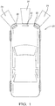
- Figure 1 schematically illustrates a vehicle 20 including sensor devices 22 that are useful for detecting an object in a vicinity of the vehicle 20.
- the sensor devices 22 respectively have detecting fields represented at 24 to allow for selectively determining or approximating a distance to a detected object and a relationship between an object and the vehicle 20, such as a rate at which the vehicle is approaching an object.
- the sensor devices 22 are RADAR devices.
- the sensor devices 22 are LIDAR devices.
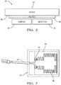
- Figure 2 schematically illustrates selected features of the sensor devices 22.
- At least one emitter 30 emits radiation into the corresponding detecting field 24.
- At least one detector 32 detects radiation reflected from an object in the corresponding detecting field 24.
- a single emitter 30 and a single detector 32 are shown for discussion purposes.
- Example embodiments include multiple emitters and multiple detectors within a sensor device 22.
- a cover 34 covers the emitter 30 and the detector 32 in this example.
- the cover 34 has an interior surface 36 facing toward the emitter 30 and the detector 32.
- the cover 34 is transparent to the radiation used for detecting objects such that the cover 34 does not interfere with radiation emitted by the emitter 30 or reflecting from an object and traveling back toward the detector 32.
- a heater 38 is provided on a portion of the cover 34.
- the heater 38 is situated on the interior surface 36 of the cover 34. Providing the heater 38 on the interior surface protects the heater 38 from environmental conditions that may otherwise compromise the operation or effectiveness of the heater 38.
- Another feature of having the heater 38 on the interior surface 36 is that the exterior of the cover 34 can be heated when desired without reaching a temperature that would be too hot for an individual to touch. This is useful, for example, when the cover 34 is situated where the cover is exposed to potential contact.
- the heater 38 is situated on the interior surface 36 where the heater 38 will not interfere with radiation passing through the cover 34 from the emitter 30 or toward the detector 32. As shown in Figure 3 , the heater 38 comprises a wire-like trace of electrically conductive material on the interior surface 36 of the cover 34. The position and arrangement of the heater 38 provides enough surface contact to sufficiently heat the cover 34 while not blocking the area through which radiation must pass for proper operation of the emitter 30 and the detector 32.
- a fluid comprising the electrically conductive material of the heater 38 is deposited onto the interior surface 36 of the cover 34 and then cured to solidify the electrically conductive material and secure the heater 38 to the cover 34.
- An example electrically conductive material comprises silver, which has material characteristics that are amenable to screen printing and other fluid deposition techniques. Silver also has characteristics that provide reliable heater performance over time.
- the cover 34 comprises glass or polycarbonate in many embodiments and silver is compatible with each when deposited onto the cover 34.
- the example heater 38 includes electrically conductive connector pads 40 that also comprise silver in this embodiment.
- the connector pads 40 in this example are screen printed or otherwise deposited onto the interior surface 36 of the cover 34.
- the connector pads 40 are formed simultaneously with forming or establishing the heater 38 in some embodiments.
- Silver connector pads 40 which may be pre-fluxed, allow for soldering ends or leads of conductors 42, such as wires, to the connector pads 40.
- the leads or terminals that are secured to the connector pads 40 are pre-fluxed and attached to the pads 40.
- the conductors 42 provide the necessary power for operating the heater 38 when needed.
- the heater 38 has a higher power per unit size compared to heating elements provided on vehicle windows such as rear defrosters.
- the heater 38 is capable of warming the cover 34 quickly to ensure reliable operation of the sensor device 22.
- the electrical resistance of the heater 38 which corresponds to its heating capacity, can be controlled by selecting different electrically conductive materials, for example.
- Embodiments of this invention avoid a need to imbed a wire into the substrate of the cover 34, which can be problematic.
- screen printing the heater 38 in place provides superior control over the position, size and configuration of the heater 38 on the cover 34 compared to a process of imbedding a wire.
- the cover 34 is typically too thin to imbed a wire without protrusions or causing distortion to the shape and appearance of the cover.
- once a wire is imbedded it becomes difficult to make an electrically conductive connection.
- the soldered connections with the deposited connector pads 40 are easier to make and do not present any distortion or appearance issues.
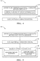
- Figure 4 is summarizes an example approach to establishing the heater 38 on the cover 34 in a flow chart 50.
- the fluid comprising the electrically conductive material is deposited onto the selected portion of the cover 34.
- At least one conductive connector pad 40 is formed also while depositing the electrically conductive material at 52.
- the fluid is deposited directly onto the interior surface 36 of the cover 34.
- the flow and pattern of the fluid are controlled to achieve the desired heater configuration and placement on the cover 34.
- the fluid is screen printed onto the cover 34.
- the fluid flow and pattern are robotically controlled as the fluid is deposited onto the cover 34.
- the electrically conductive material is cured to secure the heater 38 to the cover 34.
- the cover and the deposited conductive material are heated in a firing furnace to secure the heater 38 to the cover 34.
- curing occurs at a lower temperature to avoid damage to or distortion of the cover material.
- Another embodiment includes laminating two cover layers together.
- Each of the layers comprises glass or polycarbonate.
- the fluid comprising the electrically conductive material is deposited onto a surface of one of the layers that is positioned to face toward the other of the two layers.
- the layers are laminated together with the heater between the layers.
- Some laminated embodiments include a vinyl interlayer between the two cover layers that comprise glass or polycarbonate.
- Figure 5 includes a flowchart 60 that summarizes another example approach.
- the cover 34 comprises a plurality of layers.
- the fluid comprising the electrically conductive material is deposited onto a thin film substrate at 62.
- the deposition process may include screen printing or robotic deposition. Curing the conductive material, which was deposited in the form of the heater 38 and the connector pads 40, occurs at 64.
- the substrate becomes one of the layers of the cover 34 in this example.
- the substrate supporting the heater 38 is then secured to at least one layer of the cover 34 at 66. As shown at 68 securing the substrate to the cover layer is accomplished by adhesively securing the substrate to the cover layer. In some embodiments the adhesive is a part of the substrate while in others a separate adhesive applied between the substrate and the cover layer secures the substrate and heater 38 in place.
- some embodiments include laminating two layers of cover material together with the substrate between those layers. This approach effectively encases the heater 38 within the material of the cover 34.
- One feature of the laminating approach at 70 compared to the adhesive-based approach at 68 is that laminating the layers together provides increased thermal conductivity between the heater 38 and the material of the cover 34.
- connection for powering or controlling the heater 38 can be made with a conductive foil inserted into the laminate.
- Another option is to include a cut-out in one of the laminated layers with the connector pad 40 at least partially exposed by the cut-out.
- the examples described above provide improved heater configurations for sensor or detector covers, such as those used for RADAR or LIDAR.
- the application of a conductive material in fluid form allows for achieving desired heater configurations and performance while avoiding the difficulties associated with attempting to imbed a wire on the cover.
Landscapes
- Engineering & Computer Science (AREA)
- Radar, Positioning & Navigation (AREA)
- Remote Sensing (AREA)
- Physics & Mathematics (AREA)
- Chemical & Material Sciences (AREA)
- Computer Networks & Wireless Communication (AREA)
- General Physics & Mathematics (AREA)
- Life Sciences & Earth Sciences (AREA)
- Materials Engineering (AREA)
- Organic Chemistry (AREA)
- General Chemical & Material Sciences (AREA)
- Chemical Kinetics & Catalysis (AREA)
- Geochemistry & Mineralogy (AREA)
- Electromagnetism (AREA)
- Wood Science & Technology (AREA)
- Microelectronics & Electronic Packaging (AREA)
- Manufacturing & Machinery (AREA)
- Inorganic Chemistry (AREA)
- Composite Materials (AREA)
- Dispersion Chemistry (AREA)
- Spectroscopy & Molecular Physics (AREA)
- Surface Heating Bodies (AREA)
- Radar Systems Or Details Thereof (AREA)
- Optical Radar Systems And Details Thereof (AREA)
- Resistance Heating (AREA)
Abstract
Description
- Advances in electronics and technology have made it possible to incorporate a variety of advanced features on automotive vehicles. Various sensing technologies have been developed for detecting objects in a vicinity or pathway of a vehicle. Such systems are useful for detecting objects in the pathway or vicinity of a vehicle for parking assist and cruise control adjustment features, for example.
- More recently, automated vehicle features have become possible to allow for autonomous or semi-autonomous vehicle control. For example, cruise control systems may incorporate RADAR or light detection and ranging (LIDAR) for detecting an object or another vehicle in the pathway of a vehicle. Depending on the approach speed, the cruise control setting may be automatically adjusted to reduce the speed of the vehicle based on detecting another vehicle in the pathway of the vehicle.
- While RADAR and LIDAR systems have proven useful, including them on vehicles is not without challenges. Some environmental conditions can interfere with the ability to get a reliable reading from the device. For example, ice or snow may build up or condensation may form on the cover in amounts that reduce or block the radiation otherwise emitted from the detector or the radiation that is reflected back toward the detector. The small size of the detectors and the thin cover material make it challenging to include a heater for reducing or removing ice, snow or condensation.
- An illustrative example method of making a sensor device including a cover covering at least one of an emitter and a detector includes establishing a heater on the cover by depositing a fluid comprising an electrically conductive material onto a portion of the cover and curing the deposited electrically conductive material.
- In an example embodiment having one or more features of the method of the previous paragraph, the cover has an interior surface facing the at least one of the emitter and detector and the method comprises depositing the fluid comprising the electrically conductive material onto the interior surface.
- In an example embodiment having one or more features of the method of any of the previous paragraphs, the depositing comprises screen printing.
- In an example embodiment having one or more features of the method of any of the previous paragraphs, the depositing comprises robotically controlling a flow of the fluid and a pattern of the fluid on the portion of the cover.
- In an example embodiment having one or more features of the method of any of the previous paragraphs, the cover comprises a plurality of layers and the portion of the cover comprises one of the layers.
- In an example embodiment having one or more features of the method of any of the previous paragraphs, one of the layers comprises glass or polycarbonate, another one of the layers comprises a thin film substrate, and the method comprises depositing the fluid onto the thin film substrate and adhesively securing the thin film substrate to the one of the layers.
- In an example embodiment having one or more features of the method of any of the previous paragraphs, the plurality of layers comprises two layers that comprise glass or polycarbonate, and the method includes depositing the fluid onto a surface of one of the two layers, positioning the surface of the one of the two layers to face toward another of the two layers, and laminating the two layers together with the heater between the two layers.
- In an example embodiment having one or more features of the method of any of the previous paragraphs, the curing comprises heating the electrically conductive material.
- In an example embodiment having one or more features of the method of any of the previous paragraphs, the cover comprises glass and the heating comprises heating the cover and the electrically conductive material in a firing furnace.
- An example embodiment having one or more features of the method of any of the previous paragraphs includes forming at least one electrically conductive connector pad on the cover by depositing some of the fluid comprising the electrically conductive material onto the cover in a pad configuration.
- An example embodiment having one or more features of the method of any of the previous paragraphs includes establishing the heater and forming the at least one connector pad simultaneously.
- An illustrative example embodiment of a sensor device includes an emitter configured to emit radiation. A detector is configured to detect radiation reflected off an object. A cover covers at least one of the emitter and the detector and allows the radiation to pass through the cover. A heater comprises at least one conductor formed onto a portion of the cover from a fluid comprising an electrically conductive material that was deposited onto the portion of the cover and cured.
- In an example embodiment having one or more features of the sensor device of the previous paragraph, the cover has an interior surface facing the at least one of the emitter and the detector and the portion of the cover including the heater is on the interior surface.
- In an example embodiment having one or more features of the sensor device of any of the previous paragraphs, the heater comprises a wire-like trace comprising the electrically conductive material.
- In an example embodiment having one or more features of the sensor device of any of the previous paragraphs, the electrically conductive material comprises silver.
- In an example embodiment having one or more features of the sensor device of any of the previous paragraphs, the heater comprises at least one electrically conductive connector pad, the at least one connector pad is made of the electrically conductive material, and the electrically conductive material of the at least one connector pad was deposited in fluid form onto the cover and cured.
- An example embodiment having one or more features of the sensor device of any of the previous paragraphs includes at least one conductive wire having an end soldered to the at least one connector pad.
- In an example embodiment having one or more features of the sensor device of any of the previous paragraphs, the electrically conductive material comprises silver and the at least one connector pad comprises silver.
- In an example embodiment having one or more features of the sensor device of any of the previous paragraphs, the cover comprises a plurality of layers, one of the layers comprises at least one of glass and polycarbonate, another one of the layers comprises a thin film substrate secured to the one of the layers, and the portion of the cover comprises the thin film substrate.
- In an example embodiment having one or more features of the sensor device of any of the previous paragraphs, the cover comprises a plurality of layers, the plurality of layers comprises two layers that comprise glass or polycarbonate, the heater is on one surface of one of the two layers that faces toward another of the two layers, and the two layers are laminated together with the heater are situated between the two layers.
- The various features and advantages of at least one disclosed example embodiment will become apparent to those skilled in the art from the following detailed description. The drawings that accompany the detailed description can be briefly described as follows.
-
Figure 1 schematically illustrates a vehicle including a sensor device designed according to an embodiment of this invention. -
Figure 2 schematically illustrates selected features of a sensor device designed according to an embodiment of this invention. -
Figure 3 schematically illustrates an example heater configuration on an example cover designed according to an embodiment of this invention. -
Figure 4 is a flow chart diagram summarizing an example method according to an embodiment of this invention. -
Figure 5 is a flow chart diagram summarizing another example method. -
Figure 1 schematically illustrates avehicle 20 includingsensor devices 22 that are useful for detecting an object in a vicinity of thevehicle 20. Thesensor devices 22 respectively have detecting fields represented at 24 to allow for selectively determining or approximating a distance to a detected object and a relationship between an object and thevehicle 20, such as a rate at which the vehicle is approaching an object. In some embodiments thesensor devices 22 are RADAR devices. In other embodiments thesensor devices 22 are LIDAR devices. -
Figure 2 schematically illustrates selected features of thesensor devices 22. At least oneemitter 30 emits radiation into the corresponding detectingfield 24. At least onedetector 32 detects radiation reflected from an object in thecorresponding detecting field 24. Asingle emitter 30 and asingle detector 32 are shown for discussion purposes. Example embodiments include multiple emitters and multiple detectors within asensor device 22. - A
cover 34 covers theemitter 30 and thedetector 32 in this example. Thecover 34 has aninterior surface 36 facing toward theemitter 30 and thedetector 32. Thecover 34 is transparent to the radiation used for detecting objects such that thecover 34 does not interfere with radiation emitted by theemitter 30 or reflecting from an object and traveling back toward thedetector 32. - For situations or conditions that may allow for ice, snow or condensation to build up or form on the
cover 34, aheater 38 is provided on a portion of thecover 34. In this embodiment theheater 38 is situated on theinterior surface 36 of thecover 34. Providing theheater 38 on the interior surface protects theheater 38 from environmental conditions that may otherwise compromise the operation or effectiveness of theheater 38. Another feature of having theheater 38 on theinterior surface 36 is that the exterior of thecover 34 can be heated when desired without reaching a temperature that would be too hot for an individual to touch. This is useful, for example, when thecover 34 is situated where the cover is exposed to potential contact. - The
heater 38 is situated on theinterior surface 36 where theheater 38 will not interfere with radiation passing through thecover 34 from theemitter 30 or toward thedetector 32. As shown inFigure 3 , theheater 38 comprises a wire-like trace of electrically conductive material on theinterior surface 36 of thecover 34. The position and arrangement of theheater 38 provides enough surface contact to sufficiently heat thecover 34 while not blocking the area through which radiation must pass for proper operation of theemitter 30 and thedetector 32. - A fluid comprising the electrically conductive material of the
heater 38 is deposited onto theinterior surface 36 of thecover 34 and then cured to solidify the electrically conductive material and secure theheater 38 to thecover 34. - An example electrically conductive material comprises silver, which has material characteristics that are amenable to screen printing and other fluid deposition techniques. Silver also has characteristics that provide reliable heater performance over time. The
cover 34 comprises glass or polycarbonate in many embodiments and silver is compatible with each when deposited onto thecover 34. - The
example heater 38 includes electricallyconductive connector pads 40 that also comprise silver in this embodiment. Theconnector pads 40 in this example are screen printed or otherwise deposited onto theinterior surface 36 of thecover 34. Theconnector pads 40 are formed simultaneously with forming or establishing theheater 38 in some embodiments.Silver connector pads 40, which may be pre-fluxed, allow for soldering ends or leads ofconductors 42, such as wires, to theconnector pads 40. In some embodiments, the leads or terminals that are secured to theconnector pads 40 are pre-fluxed and attached to thepads 40. Theconductors 42 provide the necessary power for operating theheater 38 when needed. - One feature of the illustrated embodiment is that the
heater 38 has a higher power per unit size compared to heating elements provided on vehicle windows such as rear defrosters. Theheater 38 is capable of warming thecover 34 quickly to ensure reliable operation of thesensor device 22. The electrical resistance of theheater 38, which corresponds to its heating capacity, can be controlled by selecting different electrically conductive materials, for example. - Embodiments of this invention avoid a need to imbed a wire into the substrate of the
cover 34, which can be problematic. For example, screen printing theheater 38 in place provides superior control over the position, size and configuration of theheater 38 on thecover 34 compared to a process of imbedding a wire. Additionally, there are no cover distortion or external appearance issues when incorporating a depositedheater 38 on thecover 34. Thecover 34 is typically too thin to imbed a wire without protrusions or causing distortion to the shape and appearance of the cover. Additionally, once a wire is imbedded it becomes difficult to make an electrically conductive connection. The soldered connections with the depositedconnector pads 40 are easier to make and do not present any distortion or appearance issues. -
Figure 4 is summarizes an example approach to establishing theheater 38 on thecover 34 in aflow chart 50. At 52 the fluid comprising the electrically conductive material is deposited onto the selected portion of thecover 34. At least oneconductive connector pad 40 is formed also while depositing the electrically conductive material at 52. In this example, the fluid is deposited directly onto theinterior surface 36 of thecover 34. At 54, the flow and pattern of the fluid are controlled to achieve the desired heater configuration and placement on thecover 34. In some example embodiments the fluid is screen printed onto thecover 34. In other embodiments, the fluid flow and pattern are robotically controlled as the fluid is deposited onto thecover 34. At 56 the electrically conductive material is cured to secure theheater 38 to thecover 34. In some examples, such as those that include glass as the material of thecover 34, the cover and the deposited conductive material are heated in a firing furnace to secure theheater 38 to thecover 34. In other embodiments that include other cover materials, such as polycarbonate, curing occurs at a lower temperature to avoid damage to or distortion of the cover material. - Another embodiment includes laminating two cover layers together. Each of the layers comprises glass or polycarbonate. The fluid comprising the electrically conductive material is deposited onto a surface of one of the layers that is positioned to face toward the other of the two layers. The layers are laminated together with the heater between the layers. Some laminated embodiments include a vinyl interlayer between the two cover layers that comprise glass or polycarbonate.
-
Figure 5 includes aflowchart 60 that summarizes another example approach. In this case, thecover 34 comprises a plurality of layers. The fluid comprising the electrically conductive material is deposited onto a thin film substrate at 62. The deposition process may include screen printing or robotic deposition. Curing the conductive material, which was deposited in the form of theheater 38 and theconnector pads 40, occurs at 64. The substrate becomes one of the layers of thecover 34 in this example. - The substrate supporting the
heater 38 is then secured to at least one layer of thecover 34 at 66. As shown at 68 securing the substrate to the cover layer is accomplished by adhesively securing the substrate to the cover layer. In some embodiments the adhesive is a part of the substrate while in others a separate adhesive applied between the substrate and the cover layer secures the substrate andheater 38 in place. - As shown at 70 some embodiments include laminating two layers of cover material together with the substrate between those layers. This approach effectively encases the
heater 38 within the material of thecover 34. One feature of the laminating approach at 70 compared to the adhesive-based approach at 68 is that laminating the layers together provides increased thermal conductivity between theheater 38 and the material of thecover 34. - In any of the example laminated embodiments, the connection for powering or controlling the
heater 38 can be made with a conductive foil inserted into the laminate. Another option is to include a cut-out in one of the laminated layers with theconnector pad 40 at least partially exposed by the cut-out. - The examples described above provide improved heater configurations for sensor or detector covers, such as those used for RADAR or LIDAR. The application of a conductive material in fluid form allows for achieving desired heater configurations and performance while avoiding the difficulties associated with attempting to imbed a wire on the cover.
- The preceding description is exemplary rather than limiting in nature. Variations and modifications to the disclosed examples may become apparent to those skilled in the art that do not necessarily depart from the essence of this invention.
Claims (14)
- A method of making a sensor device (22) including a cover (34) covering at least one of an emitter (30) and a detector (32), the method comprising:establishing a heater (38) on the cover (34) bydepositing (52) a fluid comprising an electrically conductive material onto a portion of the cover (34) andcuring (56) the deposited electrically conductive material.
- The method of claim 1, wherein the cover (34) has an interior surface (36) facing the at least one of the emitter (30) and detector (32) and the method comprises depositing the fluid comprising the electrically conductive material onto the interior surface (36).
- The method of claim 1 or 2, wherein the depositing comprises
screen printing or
robotically controlling a flow of the fluid and a pattern of the fluid on the portion of the cover (34). - The method of any one the preceding claims, wherein
the cover (34) comprises a plurality of layers; and
the portion of the cover (34) comprises one of the layers. - The method of claim 4, wherein
one of the layers comprises glass or polycarbonate;
another one of the layers comprises a thin film substrate; and
the method comprises depositing the fluid onto the thin film substrate and adhesively securing the thin film substrate to the one of the layers. - The method of claim 4, wherein
the plurality of layers comprises two layers that comprise glass or polycarbonate; the method comprisesdepositing the fluid onto a surface of one of the two layers,positioning the surface of the one of the two layers to face toward another of the two layers, andlaminating the two layers together with the heater (38) between the two layers. - The method of any one the preceding claims, comprising simultaneously establishing the heater (38) and forming at least one electrically conductive connector pad (40) on the cover (34) by depositing some of the fluid comprising the electrically conductive material onto the cover (34) in a pad (40) configuration.
- A sensor device (22), comprising:an emitter (30) configured to emit radiation;a detector (32) configured to detect radiation reflected off an object;a cover (34) covering at least one of the emitter (30) and the detector (32), the cover (34) allowing the radiation to pass through the cover (34); anda heater (38) comprising at least one conductor formed onto a portion of the cover (34) from a fluid comprising an electrically conductive material that was deposited onto the portion of the cover (34) and cured.
- The sensor device (22) of claim 8, wherein
the cover (34) has an interior surface (36) facing the at least one of the emitter (30) and the detector (32); and
the portion of the cover (34) including the heater (38) is on the interior surface (36). - The sensor device (22) of claim 8 or 9, wherein the heater (38) comprises a wire-like trace comprising the electrically conductive material.
- The sensor device (22) of any one of the claims 8-10, wherein the electrically conductive material comprises silver.
- The sensor device (22) of any one of the claims 8-11, wherein
the heater (38) comprises at least one electrically conductive connector pad (40);
the at least one connector pad (40) is made of the electrically conductive material; and
the electrically conductive material of the at least one connector pad (40) is deposited in fluid form onto the cover (34) and cured. - The sensor device (22) of any one of the claims 8-12, wherein
the cover (34) comprises a plurality of layers;
one of the layers comprises glass or polycarbonate;
another one of the layers comprises a thin film substrate secured to the one of the layers; and
the portion of the cover (34) comprises the thin film substrate. - The sensor device (22) of any one of the claims 8-13, wherein
the cover (34) comprises a plurality of layers;
the plurality of layers comprises two layers that comprise glass or polycarbonate;
the heater (38) is on one surface of one of the two layers that faces toward another one of the two layers;
the two layers are laminated together; and
the heater (38) is situated between the two layers.
Applications Claiming Priority (1)
| Application Number | Priority Date | Filing Date | Title |
|---|---|---|---|
| US16/140,740 US20200100367A1 (en) | 2018-09-25 | 2018-09-25 | Object sensor including deposited heater |
Publications (2)
| Publication Number | Publication Date |
|---|---|
| EP3629675A1 true EP3629675A1 (en) | 2020-04-01 |
| EP3629675B1 EP3629675B1 (en) | 2022-02-09 |
Family
ID=67953576
Family Applications (1)
| Application Number | Title | Priority Date | Filing Date |
|---|---|---|---|
| EP19196846.0A Revoked EP3629675B1 (en) | 2018-09-25 | 2019-09-12 | Object sensor including deposited heater |
Country Status (5)
| Country | Link |
|---|---|
| US (2) | US20200100367A1 (en) |
| EP (1) | EP3629675B1 (en) |
| JP (1) | JP7010907B2 (en) |
| KR (2) | KR20200035218A (en) |
| CN (1) | CN110954901B (en) |
Families Citing this family (6)
| Publication number | Priority date | Publication date | Assignee | Title |
|---|---|---|---|---|
| JP7192551B2 (en) * | 2019-02-13 | 2022-12-20 | 株式会社デンソー | rangefinder |
| JP7759165B2 (en) * | 2022-03-01 | 2025-10-23 | 三恵技研工業株式会社 | Radome for vehicle-mounted radar device and manufacturing method thereof |
| US12253575B1 (en) * | 2022-07-07 | 2025-03-18 | Waymo Llc | Systems and methods for detecting failure of spring contacts |
| JP7800386B2 (en) * | 2022-11-09 | 2026-01-16 | トヨタ自動車株式会社 | Structure and performance degradation suppression device |
| WO2025105139A1 (en) * | 2023-11-13 | 2025-05-22 | Agc株式会社 | Optical sensor cover and optical sensor |
| JP7770750B2 (en) * | 2024-02-09 | 2025-11-17 | 三恵技研工業株式会社 | Snow-melting radome and its manufacturing method |
Citations (5)
| Publication number | Priority date | Publication date | Assignee | Title |
|---|---|---|---|---|
| US6674392B1 (en) * | 1999-12-24 | 2004-01-06 | Robert Bosch Gmbh | Automotive radar system |
| EP1605729A2 (en) * | 2004-04-15 | 2005-12-14 | Pilkington Plc | Electrically heated window |
| US20060086710A1 (en) * | 2004-10-07 | 2006-04-27 | Rehau Ag & Co. | Heating element on the polymer inside surface of a motor vehicle front-end module/bumper in an operative connection to a radar transmitter/receiver unit |
| KR100945258B1 (en) * | 2009-10-06 | 2010-03-03 | 삼성유리공업 주식회사 | An antifog apparatus for mirror |
| US20140070054A1 (en) * | 2010-12-31 | 2014-03-13 | Battelle Memorial Institute | Anti-icing, de-icing, and heating configuration, integration, and power methods for aircraft, aerodynamic, and complex surfaces |
Family Cites Families (37)
| Publication number | Priority date | Publication date | Assignee | Title |
|---|---|---|---|---|
| GB2091529A (en) | 1981-01-14 | 1982-07-28 | Boussois Sa | Heatable Panels |
| JPS6036359U (en) * | 1983-08-20 | 1985-03-13 | トヨタ自動車株式会社 | Anti-fog transparent material |
| US4786784A (en) * | 1987-02-17 | 1988-11-22 | Libbey-Owens-Ford Co. | Method for producing an electrically heated window assembly and resulting article |
| GB8705075D0 (en) | 1987-03-04 | 1987-04-08 | Pilkington Brothers Plc | Printing |
| US5388509A (en) * | 1993-05-05 | 1995-02-14 | Cutcher; Thomas V. | Method for making a printing screen and printing a variable thichness pattern |
| DE29803544U1 (en) | 1998-02-28 | 1998-04-23 | SEKURIT SAINT-GOBAIN Deutschland GmbH & Co. KG, 52066 Aachen | Electrically heated rear window made of laminated glass |
| JP3468212B2 (en) * | 2000-07-14 | 2003-11-17 | 株式会社デンソー | Housing for reflection measurement device |
| GB2372927A (en) * | 2001-03-01 | 2002-09-04 | Pilkington Plc | Heated vehicle window |
| US20060001727A1 (en) * | 2001-04-19 | 2006-01-05 | Haas William S | Controllable thermal warming device |
| US8084722B2 (en) | 2001-04-19 | 2011-12-27 | Haas William S | Controllable thermal warming devices |
| GB0111979D0 (en) | 2001-05-17 | 2001-07-04 | Lucas Industries Ltd | Sensing apparatus for vehicles |
| DE10126869A1 (en) | 2001-06-01 | 2002-12-19 | Saint Gobain Sekurit D Gmbh | Electrically heated disc |
| US6701835B2 (en) | 2001-07-31 | 2004-03-09 | Pilkington North America, Inc. | Method for placing indicia on substrates |
| US6559419B1 (en) * | 2001-08-03 | 2003-05-06 | Centre Luxembourgeois De Recherches Pour Le Verre Et La Ceramique S.A. (C.R.V.C.) | Multi-zone arrangement for heatable vehicle window |
| US7202445B2 (en) * | 2002-11-28 | 2007-04-10 | Nok Corporation | Door mirror heater |
| JP2006194639A (en) | 2005-01-11 | 2006-07-27 | Denso Corp | Radar equipment |
| US20060186104A1 (en) * | 2005-02-22 | 2006-08-24 | Winter John A | Fluid deposition of electrically conductive strips and articles having solid electrically conductive strips obtained therefrom |
| EP1967041B1 (en) | 2005-12-29 | 2010-08-25 | Exatec, LLC. | Busbar designs optimized for robotic dispense application |
| US20080099456A1 (en) * | 2006-10-25 | 2008-05-01 | Schwenke Robert A | Dispensing method for variable line volume |
| EP2095685B1 (en) | 2006-12-20 | 2013-02-13 | Illinois Tool Works Inc. | Flat electric heater element, in particular for glass panes of a motor vehicle |
| EP1951001A1 (en) * | 2007-01-24 | 2008-07-30 | Pilkington Italia S.p.A. | Heatable vehicle glazing |
| DE102007035027A1 (en) * | 2007-07-26 | 2009-01-29 | Adc Automotive Distance Control Systems Gmbh | Viewing window for arranging an optical sensor and / or recognition system in a vehicle |
| JP2009117292A (en) | 2007-11-09 | 2009-05-28 | Renias:Kk | Exothermic resin sheet and manufacturing method thereof |
| CN102067721B (en) * | 2008-07-08 | 2013-08-21 | 菲格垃株式会社 | Manufacturing method of heat-generating plate material, heat-generating plate material manufactured by the manufacturing method, plate-like structure, and heat-generating system |
| JP2012144217A (en) | 2011-01-14 | 2012-08-02 | Asahi Glass Co Ltd | Automotive window glass |
| US9802390B2 (en) | 2013-02-05 | 2017-10-31 | Nippon Sheet Glass Co., Ltd. | Laminted glass assembly |
| US9112278B2 (en) * | 2013-05-29 | 2015-08-18 | Delphi Technologies, Inc. | Radar device for behind windshield installations |
| JP2015025770A (en) * | 2013-07-29 | 2015-02-05 | 株式会社リコー | Detection device, vehicle |
| EP3215869B1 (en) | 2014-11-03 | 2021-12-08 | Illinois Tool Works Inc. | Transmissive front-face heater for vehicle sensor system |
| JP6592997B2 (en) * | 2015-07-10 | 2019-10-23 | 横浜ゴム株式会社 | Printing method |
| JP6665691B2 (en) | 2016-06-01 | 2020-03-13 | 豊田合成株式会社 | Decorative parts for vehicles |
| GB201610639D0 (en) | 2016-06-17 | 2016-08-03 | Univ Swansea | Glass laminate structure |
| US10923252B2 (en) * | 2016-09-29 | 2021-02-16 | Kyocera Corporation | Resistor, circuit board, and electronic device |
| DE102016225668B4 (en) | 2016-12-20 | 2024-03-21 | Magna Exteriors Gmbh | Component system with a plastic component and a sensor |
| JP6905831B2 (en) | 2017-01-19 | 2021-07-21 | 日本板硝子株式会社 | Laminated glass |
| EP4685122A3 (en) | 2017-08-07 | 2026-04-15 | AGC Glass Europe | Protective housing for a sensing device |
| CN110635240B (en) | 2019-09-11 | 2024-05-17 | 宁波信泰机械有限公司 | Heatable radome structure and production method thereof |
-
2018
- 2018-09-25 US US16/140,740 patent/US20200100367A1/en not_active Abandoned
-
2019
- 2019-09-12 EP EP19196846.0A patent/EP3629675B1/en not_active Revoked
- 2019-09-18 JP JP2019169181A patent/JP7010907B2/en active Active
- 2019-09-20 KR KR1020190115798A patent/KR20200035218A/en not_active Ceased
- 2019-09-24 CN CN201910903613.9A patent/CN110954901B/en active Active
-
2021
- 2021-09-17 KR KR1020210124576A patent/KR102496575B1/en active Active
-
2023
- 2023-03-28 US US18/127,156 patent/US12439524B2/en active Active
Patent Citations (5)
| Publication number | Priority date | Publication date | Assignee | Title |
|---|---|---|---|---|
| US6674392B1 (en) * | 1999-12-24 | 2004-01-06 | Robert Bosch Gmbh | Automotive radar system |
| EP1605729A2 (en) * | 2004-04-15 | 2005-12-14 | Pilkington Plc | Electrically heated window |
| US20060086710A1 (en) * | 2004-10-07 | 2006-04-27 | Rehau Ag & Co. | Heating element on the polymer inside surface of a motor vehicle front-end module/bumper in an operative connection to a radar transmitter/receiver unit |
| KR100945258B1 (en) * | 2009-10-06 | 2010-03-03 | 삼성유리공업 주식회사 | An antifog apparatus for mirror |
| US20140070054A1 (en) * | 2010-12-31 | 2014-03-13 | Battelle Memorial Institute | Anti-icing, de-icing, and heating configuration, integration, and power methods for aircraft, aerodynamic, and complex surfaces |
Also Published As
| Publication number | Publication date |
|---|---|
| US12439524B2 (en) | 2025-10-07 |
| EP3629675B1 (en) | 2022-02-09 |
| CN110954901A (en) | 2020-04-03 |
| JP2020052042A (en) | 2020-04-02 |
| CN110954901B (en) | 2023-11-03 |
| JP7010907B2 (en) | 2022-02-10 |
| US20200100367A1 (en) | 2020-03-26 |
| KR102496575B1 (en) | 2023-02-07 |
| US20230240015A1 (en) | 2023-07-27 |
| KR20200035218A (en) | 2020-04-02 |
| KR20210118788A (en) | 2021-10-01 |
Similar Documents
| Publication | Publication Date | Title |
|---|---|---|
| US12439524B2 (en) | Object sensor including a deposited heater and method of forming same | |
| JP5808419B2 (en) | Panel heater with temperature monitoring function | |
| US11603051B2 (en) | Decorative component for vehicle | |
| EP3215869B1 (en) | Transmissive front-face heater for vehicle sensor system | |
| US10775948B2 (en) | Touch control glazing with a capacitive touch sensitive device and a light emitting diode and the manufacturing | |
| US10694587B2 (en) | Electrically heatable composite pane having a capacitive switching region | |
| JP6448809B2 (en) | Heatable laminated side glass | |
| KR20190058291A (en) | Heating Device And Outside Information Acquiring Device of Car Having the Device Thereof | |
| EA035186B1 (en) | Electrically heatable glass panel with switch region | |
| KR20190013861A (en) | Vehicle glass for head-up display, vehicle having the same, and manufacturing thereof | |
| JP7461121B2 (en) | Screen Heater System | |
| JP7527872B2 (en) | Heater units and their applications | |
| CN221081580U (en) | Heating panel, laser radar and car | |
| JP2021111495A (en) | Heater unit and applied article thereof | |
| US20250275019A1 (en) | Transparent Flexible Foil Heater | |
| US20250196807A1 (en) | Window Inductive Heating System | |
| CN121114926A (en) | Housing structure of radar device for vehicle |
Legal Events
| Date | Code | Title | Description |
|---|---|---|---|
| PUAI | Public reference made under article 153(3) epc to a published international application that has entered the european phase |
Free format text: ORIGINAL CODE: 0009012 |
|
| STAA | Information on the status of an ep patent application or granted ep patent |
Free format text: STATUS: THE APPLICATION HAS BEEN PUBLISHED |
|
| AK | Designated contracting states |
Kind code of ref document: A1 Designated state(s): AL AT BE BG CH CY CZ DE DK EE ES FI FR GB GR HR HU IE IS IT LI LT LU LV MC MK MT NL NO PL PT RO RS SE SI SK SM TR |
|
| AX | Request for extension of the european patent |
Extension state: BA ME |
|
| STAA | Information on the status of an ep patent application or granted ep patent |
Free format text: STATUS: REQUEST FOR EXAMINATION WAS MADE |
|
| 17P | Request for examination filed |
Effective date: 20200930 |
|
| RBV | Designated contracting states (corrected) |
Designated state(s): AL AT BE BG CH CY CZ DE DK EE ES FI FR GB GR HR HU IE IS IT LI LT LU LV MC MK MT NL NO PL PT RO RS SE SI SK SM TR |
|
| STAA | Information on the status of an ep patent application or granted ep patent |
Free format text: STATUS: EXAMINATION IS IN PROGRESS |
|
| 17Q | First examination report despatched |
Effective date: 20201201 |
|
| GRAP | Despatch of communication of intention to grant a patent |
Free format text: ORIGINAL CODE: EPIDOSNIGR1 |
|
| STAA | Information on the status of an ep patent application or granted ep patent |
Free format text: STATUS: GRANT OF PATENT IS INTENDED |
|
| INTG | Intention to grant announced |
Effective date: 20211025 |
|
| GRAS | Grant fee paid |
Free format text: ORIGINAL CODE: EPIDOSNIGR3 |
|
| RAP1 | Party data changed (applicant data changed or rights of an application transferred) |
Owner name: APTIV TECHNOLOGIES LIMITED |
|
| GRAA | (expected) grant |
Free format text: ORIGINAL CODE: 0009210 |
|
| STAA | Information on the status of an ep patent application or granted ep patent |
Free format text: STATUS: THE PATENT HAS BEEN GRANTED |
|
| AK | Designated contracting states |
Kind code of ref document: B1 Designated state(s): AL AT BE BG CH CY CZ DE DK EE ES FI FR GB GR HR HU IE IS IT LI LT LU LV MC MK MT NL NO PL PT RO RS SE SI SK SM TR |
|
| REG | Reference to a national code |
Ref country code: GB Ref legal event code: FG4D |
|
| REG | Reference to a national code |
Ref country code: CH Ref legal event code: EP Ref country code: AT Ref legal event code: REF Ref document number: 1468288 Country of ref document: AT Kind code of ref document: T Effective date: 20220215 |
|
| REG | Reference to a national code |
Ref country code: IE Ref legal event code: FG4D |
|
| REG | Reference to a national code |
Ref country code: DE Ref legal event code: R096 Ref document number: 602019011444 Country of ref document: DE |
|
| REG | Reference to a national code |
Ref country code: LT Ref legal event code: MG9D |
|
| REG | Reference to a national code |
Ref country code: NL Ref legal event code: MP Effective date: 20220209 |
|
| REG | Reference to a national code |
Ref country code: AT Ref legal event code: MK05 Ref document number: 1468288 Country of ref document: AT Kind code of ref document: T Effective date: 20220209 |
|
| PG25 | Lapsed in a contracting state [announced via postgrant information from national office to epo] |
Ref country code: SE Free format text: LAPSE BECAUSE OF FAILURE TO SUBMIT A TRANSLATION OF THE DESCRIPTION OR TO PAY THE FEE WITHIN THE PRESCRIBED TIME-LIMIT Effective date: 20220209 Ref country code: RS Free format text: LAPSE BECAUSE OF FAILURE TO SUBMIT A TRANSLATION OF THE DESCRIPTION OR TO PAY THE FEE WITHIN THE PRESCRIBED TIME-LIMIT Effective date: 20220209 Ref country code: PT Free format text: LAPSE BECAUSE OF FAILURE TO SUBMIT A TRANSLATION OF THE DESCRIPTION OR TO PAY THE FEE WITHIN THE PRESCRIBED TIME-LIMIT Effective date: 20220609 Ref country code: NO Free format text: LAPSE BECAUSE OF FAILURE TO SUBMIT A TRANSLATION OF THE DESCRIPTION OR TO PAY THE FEE WITHIN THE PRESCRIBED TIME-LIMIT Effective date: 20220509 Ref country code: NL Free format text: LAPSE BECAUSE OF FAILURE TO SUBMIT A TRANSLATION OF THE DESCRIPTION OR TO PAY THE FEE WITHIN THE PRESCRIBED TIME-LIMIT Effective date: 20220209 Ref country code: LT Free format text: LAPSE BECAUSE OF FAILURE TO SUBMIT A TRANSLATION OF THE DESCRIPTION OR TO PAY THE FEE WITHIN THE PRESCRIBED TIME-LIMIT Effective date: 20220209 Ref country code: HR Free format text: LAPSE BECAUSE OF FAILURE TO SUBMIT A TRANSLATION OF THE DESCRIPTION OR TO PAY THE FEE WITHIN THE PRESCRIBED TIME-LIMIT Effective date: 20220209 Ref country code: ES Free format text: LAPSE BECAUSE OF FAILURE TO SUBMIT A TRANSLATION OF THE DESCRIPTION OR TO PAY THE FEE WITHIN THE PRESCRIBED TIME-LIMIT Effective date: 20220209 Ref country code: BG Free format text: LAPSE BECAUSE OF FAILURE TO SUBMIT A TRANSLATION OF THE DESCRIPTION OR TO PAY THE FEE WITHIN THE PRESCRIBED TIME-LIMIT Effective date: 20220509 |
|
| PG25 | Lapsed in a contracting state [announced via postgrant information from national office to epo] |
Ref country code: PL Free format text: LAPSE BECAUSE OF FAILURE TO SUBMIT A TRANSLATION OF THE DESCRIPTION OR TO PAY THE FEE WITHIN THE PRESCRIBED TIME-LIMIT Effective date: 20220209 Ref country code: LV Free format text: LAPSE BECAUSE OF FAILURE TO SUBMIT A TRANSLATION OF THE DESCRIPTION OR TO PAY THE FEE WITHIN THE PRESCRIBED TIME-LIMIT Effective date: 20220209 Ref country code: GR Free format text: LAPSE BECAUSE OF FAILURE TO SUBMIT A TRANSLATION OF THE DESCRIPTION OR TO PAY THE FEE WITHIN THE PRESCRIBED TIME-LIMIT Effective date: 20220510 Ref country code: FI Free format text: LAPSE BECAUSE OF FAILURE TO SUBMIT A TRANSLATION OF THE DESCRIPTION OR TO PAY THE FEE WITHIN THE PRESCRIBED TIME-LIMIT Effective date: 20220209 Ref country code: AT Free format text: LAPSE BECAUSE OF FAILURE TO SUBMIT A TRANSLATION OF THE DESCRIPTION OR TO PAY THE FEE WITHIN THE PRESCRIBED TIME-LIMIT Effective date: 20220209 |
|
| PG25 | Lapsed in a contracting state [announced via postgrant information from national office to epo] |
Ref country code: IS Free format text: LAPSE BECAUSE OF FAILURE TO SUBMIT A TRANSLATION OF THE DESCRIPTION OR TO PAY THE FEE WITHIN THE PRESCRIBED TIME-LIMIT Effective date: 20220609 |
|
| PG25 | Lapsed in a contracting state [announced via postgrant information from national office to epo] |
Ref country code: SM Free format text: LAPSE BECAUSE OF FAILURE TO SUBMIT A TRANSLATION OF THE DESCRIPTION OR TO PAY THE FEE WITHIN THE PRESCRIBED TIME-LIMIT Effective date: 20220209 Ref country code: SK Free format text: LAPSE BECAUSE OF FAILURE TO SUBMIT A TRANSLATION OF THE DESCRIPTION OR TO PAY THE FEE WITHIN THE PRESCRIBED TIME-LIMIT Effective date: 20220209 Ref country code: RO Free format text: LAPSE BECAUSE OF FAILURE TO SUBMIT A TRANSLATION OF THE DESCRIPTION OR TO PAY THE FEE WITHIN THE PRESCRIBED TIME-LIMIT Effective date: 20220209 Ref country code: EE Free format text: LAPSE BECAUSE OF FAILURE TO SUBMIT A TRANSLATION OF THE DESCRIPTION OR TO PAY THE FEE WITHIN THE PRESCRIBED TIME-LIMIT Effective date: 20220209 Ref country code: DK Free format text: LAPSE BECAUSE OF FAILURE TO SUBMIT A TRANSLATION OF THE DESCRIPTION OR TO PAY THE FEE WITHIN THE PRESCRIBED TIME-LIMIT Effective date: 20220209 Ref country code: CZ Free format text: LAPSE BECAUSE OF FAILURE TO SUBMIT A TRANSLATION OF THE DESCRIPTION OR TO PAY THE FEE WITHIN THE PRESCRIBED TIME-LIMIT Effective date: 20220209 |
|
| REG | Reference to a national code |
Ref country code: DE Ref legal event code: R026 Ref document number: 602019011444 Country of ref document: DE |
|
| PLBI | Opposition filed |
Free format text: ORIGINAL CODE: 0009260 |
|
| PLAX | Notice of opposition and request to file observation + time limit sent |
Free format text: ORIGINAL CODE: EPIDOSNOBS2 |
|
| PG25 | Lapsed in a contracting state [announced via postgrant information from national office to epo] |
Ref country code: AL Free format text: LAPSE BECAUSE OF FAILURE TO SUBMIT A TRANSLATION OF THE DESCRIPTION OR TO PAY THE FEE WITHIN THE PRESCRIBED TIME-LIMIT Effective date: 20220209 |
|
| 26 | Opposition filed |
Opponent name: AGC GLASS EUROPE Effective date: 20221108 |
|
| PG25 | Lapsed in a contracting state [announced via postgrant information from national office to epo] |
Ref country code: SI Free format text: LAPSE BECAUSE OF FAILURE TO SUBMIT A TRANSLATION OF THE DESCRIPTION OR TO PAY THE FEE WITHIN THE PRESCRIBED TIME-LIMIT Effective date: 20220209 |
|
| PLBB | Reply of patent proprietor to notice(s) of opposition received |
Free format text: ORIGINAL CODE: EPIDOSNOBS3 |
|
| RAP4 | Party data changed (patent owner data changed or rights of a patent transferred) |
Owner name: APTIV TECHNOLOGIES LIMITED |
|
| PG25 | Lapsed in a contracting state [announced via postgrant information from national office to epo] |
Ref country code: MC Free format text: LAPSE BECAUSE OF FAILURE TO SUBMIT A TRANSLATION OF THE DESCRIPTION OR TO PAY THE FEE WITHIN THE PRESCRIBED TIME-LIMIT Effective date: 20220209 |
|
| REG | Reference to a national code |
Ref country code: CH Ref legal event code: PL |
|
| REG | Reference to a national code |
Ref country code: BE Ref legal event code: MM Effective date: 20220930 |
|
| P01 | Opt-out of the competence of the unified patent court (upc) registered |
Effective date: 20230424 |
|
| PG25 | Lapsed in a contracting state [announced via postgrant information from national office to epo] |
Ref country code: LU Free format text: LAPSE BECAUSE OF NON-PAYMENT OF DUE FEES Effective date: 20220912 |
|
| PG25 | Lapsed in a contracting state [announced via postgrant information from national office to epo] |
Ref country code: LI Free format text: LAPSE BECAUSE OF NON-PAYMENT OF DUE FEES Effective date: 20220930 Ref country code: IT Free format text: LAPSE BECAUSE OF FAILURE TO SUBMIT A TRANSLATION OF THE DESCRIPTION OR TO PAY THE FEE WITHIN THE PRESCRIBED TIME-LIMIT Effective date: 20220209 Ref country code: IE Free format text: LAPSE BECAUSE OF NON-PAYMENT OF DUE FEES Effective date: 20220912 Ref country code: CH Free format text: LAPSE BECAUSE OF NON-PAYMENT OF DUE FEES Effective date: 20220930 |
|
| PG25 | Lapsed in a contracting state [announced via postgrant information from national office to epo] |
Ref country code: BE Free format text: LAPSE BECAUSE OF NON-PAYMENT OF DUE FEES Effective date: 20220930 |
|
| PGFP | Annual fee paid to national office [announced via postgrant information from national office to epo] |
Ref country code: GB Payment date: 20230914 Year of fee payment: 5 |
|
| PGFP | Annual fee paid to national office [announced via postgrant information from national office to epo] |
Ref country code: FR Payment date: 20230912 Year of fee payment: 5 Ref country code: DE Payment date: 20230921 Year of fee payment: 5 |
|
| PLAB | Opposition data, opponent's data or that of the opponent's representative modified |
Free format text: ORIGINAL CODE: 0009299OPPO |
|
| R26 | Opposition filed (corrected) |
Opponent name: AGC GLASS EUROPE Effective date: 20221108 |
|
| REG | Reference to a national code |
Ref country code: DE Ref legal event code: R103 Ref document number: 602019011444 Country of ref document: DE Ref country code: DE Ref legal event code: R064 Ref document number: 602019011444 Country of ref document: DE |
|
| RDAF | Communication despatched that patent is revoked |
Free format text: ORIGINAL CODE: EPIDOSNREV1 |
|
| PG25 | Lapsed in a contracting state [announced via postgrant information from national office to epo] |
Ref country code: HU Free format text: LAPSE BECAUSE OF FAILURE TO SUBMIT A TRANSLATION OF THE DESCRIPTION OR TO PAY THE FEE WITHIN THE PRESCRIBED TIME-LIMIT; INVALID AB INITIO Effective date: 20190912 |
|
| PG25 | Lapsed in a contracting state [announced via postgrant information from national office to epo] |
Ref country code: CY Free format text: LAPSE BECAUSE OF FAILURE TO SUBMIT A TRANSLATION OF THE DESCRIPTION OR TO PAY THE FEE WITHIN THE PRESCRIBED TIME-LIMIT Effective date: 20220209 |
|
| PG25 | Lapsed in a contracting state [announced via postgrant information from national office to epo] |
Ref country code: MK Free format text: LAPSE BECAUSE OF FAILURE TO SUBMIT A TRANSLATION OF THE DESCRIPTION OR TO PAY THE FEE WITHIN THE PRESCRIBED TIME-LIMIT Effective date: 20220209 |
|
| RDAG | Patent revoked |
Free format text: ORIGINAL CODE: 0009271 |
|
| STAA | Information on the status of an ep patent application or granted ep patent |
Free format text: STATUS: PATENT REVOKED |
|
| REG | Reference to a national code |
Ref country code: CH Ref legal event code: PL |
|
| 27W | Patent revoked |
Effective date: 20240307 |
|
| GBPR | Gb: patent revoked under art. 102 of the ep convention designating the uk as contracting state |
Effective date: 20240307 |
|
| PG25 | Lapsed in a contracting state [announced via postgrant information from national office to epo] |
Ref country code: TR Free format text: LAPSE BECAUSE OF FAILURE TO SUBMIT A TRANSLATION OF THE DESCRIPTION OR TO PAY THE FEE WITHIN THE PRESCRIBED TIME-LIMIT Effective date: 20220209 |