EP3629512B1 - Method and node in a wireless communication network - Google Patents
Method and node in a wireless communication network Download PDFInfo
- Publication number
- EP3629512B1 EP3629512B1 EP19202611.0A EP19202611A EP3629512B1 EP 3629512 B1 EP3629512 B1 EP 3629512B1 EP 19202611 A EP19202611 A EP 19202611A EP 3629512 B1 EP3629512 B1 EP 3629512B1
- Authority
- EP
- European Patent Office
- Prior art keywords
- ues
- group
- pilot
- sequences
- network node
- Prior art date
- Legal status (The legal status is an assumption and is not a legal conclusion. Google has not performed a legal analysis and makes no representation as to the accuracy of the status listed.)
- Active
Links
- 238000000034 method Methods 0.000 title claims description 67
- 238000004891 communication Methods 0.000 title description 46
- 230000005540 biological transmission Effects 0.000 claims description 69
- 238000012545 processing Methods 0.000 claims description 54
- 238000004590 computer program Methods 0.000 claims description 14
- 230000009471 action Effects 0.000 description 37
- 239000013598 vector Substances 0.000 description 23
- 238000001914 filtration Methods 0.000 description 18
- 238000011109 contamination Methods 0.000 description 14
- 238000010586 diagram Methods 0.000 description 13
- 230000002452 interceptive effect Effects 0.000 description 12
- 239000011159 matrix material Substances 0.000 description 7
- 230000003595 spectral effect Effects 0.000 description 7
- 238000003491 array Methods 0.000 description 6
- 238000001514 detection method Methods 0.000 description 5
- 230000008901 benefit Effects 0.000 description 4
- 238000005562 fading Methods 0.000 description 4
- 230000001965 increasing effect Effects 0.000 description 4
- 230000001419 dependent effect Effects 0.000 description 3
- 230000006870 function Effects 0.000 description 3
- 230000014509 gene expression Effects 0.000 description 3
- 230000008569 process Effects 0.000 description 3
- 230000001413 cellular effect Effects 0.000 description 2
- 230000008859 change Effects 0.000 description 2
- 238000010276 construction Methods 0.000 description 2
- 238000005516 engineering process Methods 0.000 description 2
- 230000006872 improvement Effects 0.000 description 2
- 230000007774 longterm Effects 0.000 description 2
- 230000003287 optical effect Effects 0.000 description 2
- 230000008054 signal transmission Effects 0.000 description 2
- 230000011664 signaling Effects 0.000 description 2
- 238000012549 training Methods 0.000 description 2
- 241000760358 Enodes Species 0.000 description 1
- XUIMIQQOPSSXEZ-UHFFFAOYSA-N Silicon Chemical compound [Si] XUIMIQQOPSSXEZ-UHFFFAOYSA-N 0.000 description 1
- 230000004075 alteration Effects 0.000 description 1
- 238000013459 approach Methods 0.000 description 1
- 230000009286 beneficial effect Effects 0.000 description 1
- 230000015556 catabolic process Effects 0.000 description 1
- 238000006731 degradation reaction Methods 0.000 description 1
- 238000011161 development Methods 0.000 description 1
- 239000010432 diamond Substances 0.000 description 1
- 238000011156 evaluation Methods 0.000 description 1
- 230000000763 evoking effect Effects 0.000 description 1
- 230000007246 mechanism Effects 0.000 description 1
- 230000009467 reduction Effects 0.000 description 1
- 230000004044 response Effects 0.000 description 1
- 229910052710 silicon Inorganic materials 0.000 description 1
- 239000010703 silicon Substances 0.000 description 1
- 238000006467 substitution reaction Methods 0.000 description 1
Images


Classifications
-
- H—ELECTRICITY
- H04—ELECTRIC COMMUNICATION TECHNIQUE
- H04L—TRANSMISSION OF DIGITAL INFORMATION, e.g. TELEGRAPHIC COMMUNICATION
- H04L5/00—Arrangements affording multiple use of the transmission path
- H04L5/003—Arrangements for allocating sub-channels of the transmission path
- H04L5/0048—Allocation of pilot signals, i.e. of signals known to the receiver
-
- H—ELECTRICITY
- H04—ELECTRIC COMMUNICATION TECHNIQUE
- H04B—TRANSMISSION
- H04B1/00—Details of transmission systems, not covered by a single one of groups H04B3/00 - H04B13/00; Details of transmission systems not characterised by the medium used for transmission
- H04B1/69—Spread spectrum techniques
- H04B1/707—Spread spectrum techniques using direct sequence modulation
- H04B1/7097—Interference-related aspects
- H04B1/7103—Interference-related aspects the interference being multiple access interference
- H04B1/7107—Subtractive interference cancellation
-
- H—ELECTRICITY
- H04—ELECTRIC COMMUNICATION TECHNIQUE
- H04B—TRANSMISSION
- H04B7/00—Radio transmission systems, i.e. using radiation field
- H04B7/02—Diversity systems; Multi-antenna system, i.e. transmission or reception using multiple antennas
- H04B7/04—Diversity systems; Multi-antenna system, i.e. transmission or reception using multiple antennas using two or more spaced independent antennas
- H04B7/0413—MIMO systems
-
- H—ELECTRICITY
- H04—ELECTRIC COMMUNICATION TECHNIQUE
- H04J—MULTIPLEX COMMUNICATION
- H04J11/00—Orthogonal multiplex systems, e.g. using WALSH codes
- H04J11/0023—Interference mitigation or co-ordination
- H04J11/0026—Interference mitigation or co-ordination of multi-user interference
- H04J11/0036—Interference mitigation or co-ordination of multi-user interference at the receiver
- H04J11/004—Interference mitigation or co-ordination of multi-user interference at the receiver using regenerative subtractive interference cancellation
- H04J11/0043—Interference mitigation or co-ordination of multi-user interference at the receiver using regenerative subtractive interference cancellation by grouping or ordering the users
-
- H—ELECTRICITY
- H04—ELECTRIC COMMUNICATION TECHNIQUE
- H04L—TRANSMISSION OF DIGITAL INFORMATION, e.g. TELEGRAPHIC COMMUNICATION
- H04L25/00—Baseband systems
- H04L25/02—Details ; arrangements for supplying electrical power along data transmission lines
- H04L25/0202—Channel estimation
- H04L25/0224—Channel estimation using sounding signals
- H04L25/0226—Channel estimation using sounding signals sounding signals per se
-
- H—ELECTRICITY
- H04—ELECTRIC COMMUNICATION TECHNIQUE
- H04L—TRANSMISSION OF DIGITAL INFORMATION, e.g. TELEGRAPHIC COMMUNICATION
- H04L5/00—Arrangements affording multiple use of the transmission path
- H04L5/0001—Arrangements for dividing the transmission path
- H04L5/0003—Two-dimensional division
- H04L5/0005—Time-frequency
- H04L5/0007—Time-frequency the frequencies being orthogonal, e.g. OFDM(A), DMT
-
- H—ELECTRICITY
- H04—ELECTRIC COMMUNICATION TECHNIQUE
- H04L—TRANSMISSION OF DIGITAL INFORMATION, e.g. TELEGRAPHIC COMMUNICATION
- H04L5/00—Arrangements affording multiple use of the transmission path
- H04L5/003—Arrangements for allocating sub-channels of the transmission path
- H04L5/0032—Distributed allocation, i.e. involving a plurality of allocating devices, each making partial allocation
- H04L5/0035—Resource allocation in a cooperative multipoint environment
-
- H—ELECTRICITY
- H04—ELECTRIC COMMUNICATION TECHNIQUE
- H04L—TRANSMISSION OF DIGITAL INFORMATION, e.g. TELEGRAPHIC COMMUNICATION
- H04L5/00—Arrangements affording multiple use of the transmission path
- H04L5/003—Arrangements for allocating sub-channels of the transmission path
- H04L5/0053—Allocation of signaling, i.e. of overhead other than pilot signals
-
- H—ELECTRICITY
- H04—ELECTRIC COMMUNICATION TECHNIQUE
- H04B—TRANSMISSION
- H04B2201/00—Indexing scheme relating to details of transmission systems not covered by a single group of H04B3/00 - H04B13/00
- H04B2201/69—Orthogonal indexing scheme relating to spread spectrum techniques in general
- H04B2201/707—Orthogonal indexing scheme relating to spread spectrum techniques in general relating to direct sequence modulation
- H04B2201/70701—Orthogonal indexing scheme relating to spread spectrum techniques in general relating to direct sequence modulation featuring pilot assisted reception
Landscapes
- Engineering & Computer Science (AREA)
- Signal Processing (AREA)
- Computer Networks & Wireless Communication (AREA)
- Power Engineering (AREA)
- Mobile Radio Communication Systems (AREA)
- Radio Transmission System (AREA)
Description
- Implementations described herein generally relate to a network node and a method in a network node. In particular is herein described a mechanism for grouping User Equipment (UE) into different UE groups.
- The number of active antenna elements in an antenna array is increasing over time as may be observed by recent releases of Long Term Evolution (LTE) system where the newer releases support Multiple-Input Multiple-Output (MIMO) links with an increasing amount of antennas. Further increase in number of antenna elements, particularly at the base stations, is envisioned as an attractive physical-layer solution to improve the spectral efficiency of future communication systems such as fifth generation (5G) systems and in response to ever-increasing data traffic. So the term Massive MIMO (mMIMO) is employed to refer to the cases where the receivers and/ or the transmitters enjoy many active antenna elements, such as e.g. hundreds of antenna elements. These types of mMIMO antenna systems are also known as Large-Scale Antenna Systems, Very Large MIMO, Hyper MIMO, Full-Dimension MIMO, Many-Antenna Base Stations and/ or ARGOS.
- To enable Space-Division Multiple-Access (SDMA) with mMIMO, the channel matrix between transmit antennas and receive antennas should be known. The channel estimation is an essential part as it allows separating the data streams associated with different User Equipment (UEs), served by the base station. In fact, one can view the channel matrix/ vectors for example between different UEs and the base station as a spatial signature generated by the environment where one needs to learn such a random set of spatial signatures. Having learned the so-called spatial signatures, one can then try to perform spatial filtering (e.g. projection of the received baseband signals in the signal space spanned by the estimated channel vectors) at the receiver or spatial pre-coding (e.g. transmission of the data sequences in a properly chosen subspace of the signal space spanned by the estimated channel matrix) at the transmitter to ensure concurrent transmission and reception of multiple UEs with a negligible or no inter-user interference.
- To estimate the channel between different nodes in a wireless communication network, i.e. UEs, base station/ network node, access node, radio head, hyper transmitters, etc., one generally transmits pilot sequences known both by the transmitter and the receiver. These known pilot sequences are also referred to as reference signals/ symbols or pilot signals/symbols. These expressions may sometimes be used alternatively for denoting the same thing as pilot sequences. Using these pilot sequences, the unknown radio channel between transmit and receive nodes may be estimated. Sending the pilot sequences in general leads to a loss in spectrally efficiency as it requires additional time-frequency resources to be used. The number and density of pilot sequences respectively depends on the number of antennas and time-frequency characteristics of the channel.
- To learn the channel (e.g., the equivalent complex number affecting the transmitted signals for narrowband radio channels), at least one linear equation per number of unknowns is needed to find a meaningful estimation of the channel in general and in particular when the antenna spacing are configured such that it results to a full rank channel matrix. So to learn for example a downlink channel from a base station with nt antennas to K users each with nr antennas, at least nt pilots signal are needed; i.e. one pilot per antenna, or alternatively nt orthogonal sequences of length nt (or spanning a subspace with dimension nt) are required. For uplink transmission, however the required number of pilot sequences changes to Knr. It may be noted that the number of pilot sequences increases linearly with the number of antennas and hence it does not scale favourably for massive antenna arrays.
- A remedy to this shortcoming is to use the channel reciprocity. That is when the uplink and downlink transmissions occur over the same frequency band the uplink and downlink channel remains the same at a given time instant. So the Time-Division Duplex (TDD) operation allows using the number of pilot sequences according to:

- In practice, the typical number of antennas at User Equipment (UE), such as e.g. a mobile telephone, a computer tablet, a laptop with wireless capability or similar portable device, is kept low to allow smaller size, simpler processing for a longer battery life time and cheaper UE. However the base station may afford a larger number of antennas, where nr « nt. So for example for a scenario with massive MIMO at the base station and K UEs each with a single antenna the required number of pilot sequences in order to learn the uplink and downlink channel in TDD mode is equal to the number of UEs. For massive MIMO, it is expected to have K « nt, which results to an affordable overhead associated to the pilot sequences.
- The density of the pilot sequences depends on the radio channel characteristic. The characteristics of the radio channel change over time and frequency. However the variations in time depend on the mobility of the UEs. The faster the UEs move, the faster the channel in time changes due to a larger Doppler frequency. The radio channel can be assumed unchanged within the coherence time Tc, which is a function of the carrier frequency and the velocity of the UEs. So to learn the channel between transmit and receive antennas over a coherence time, at least one pilot symbol per coherence time is needed. Similarly, the radio channel varies in frequency. However the changes in the frequency are generally characterised by the coherence bandwidth, Bc which depends on the delay profile of the channel and the symbol duration.
- To sum-up, in order to learn the radio channel in the time-frequency grid in the TDD mode for mMIMO communication in a cell with K UEs each with a single antenna, K orthogonal pilot sequences, each associated to a UE, are required over a time-frequency grid of the size Tc × Bc.
-
Figure 1A depicts a conventional transmission frame structure for Time-Division Duplex (TDD) communications where each frame is consisted of multiple subframes. In theFigure 1A , there are L subframes. Each subframe comprises pilot data, for channel estimation, control signals for uplink and downlink transmission and then the data transmission. Each subframe is a grid of Resource Elements (REs) over time and frequency, where each resource element consumes one symbol duration and one subcarrier. The guard intervals may also be situated between uplink and downlink transmissions as well as between the pilot region and data region, which however for simplicity of exposition have been omitted. - Non-orthogonal multiple-access is the paradigm to concurrently schedule multiple UEs over the same time-frequency resource element. One appealing approach to separate the uplink superimposed data streams may be to use spatial domain provided by a plurality of antennas. Toward this end, the receiver needs to estimate the channels from each UE and then using the estimated channels to perform spatial filtering to remove the cross-talk, i.e. interference, among the superimposed streams.
-
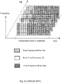
Figure 1B illustrates the uplink transmission for K UEs over shared time-frequency resource elements where each frame has two regions: pilot region and data region which also comprises the control data. - To overcome the pilot contamination, it is required to ensure the pilot sequences transmitted in the time-frequency grid dedicated to the pilot transmissions are orthogonal to one another. One example of orthogonal pilot transmission is illustrated in
Figure 1C . The conventional solution is to schedule multiple UEs where the total number of UEs in the cell is less than the total number of orthogonal sequences.Figure 1C depicts the one example for orthogonal pilot transmission obtained by Time-Division Multiplexing (TDM) in the pilot region, and non-orthogonal data transmission over shared uplink resources. It is understood that in the pilot region one may use Frequency-Division Multiplexing (FDM) or combination of FDM and TDM. For uplink transmission however, the UEs may employ the pilot sequences over the entire sub-band, for which TDM or Code-Division Multiplexing (CDM) over pilot may be used, such as pilots with covering code used in LTE. - However, the maximum number of orthogonal sequences that may be placed in the pilot time-frequency grid is limited. This consequently puts a limit on the number of scheduled UEs regardless of the number of antennas. So the prior art is incapable to allow UE scheduling beyond half of the coherence time and also leads to intra-cell (for pilot sequence reuse within a cell) or inter-cell interference for reused pilot sequences across different cells.
- For TDD mMIMO communications when the number of antennas is very large, the limiting factor for achieving high network throughput is the limited number of orthogonal pilot sequences. For radio channels with the coherence time Tc symbols, for high number of antennas, in order to maximise the aggregate throughput, it is optimal to allocate half of the coherence time for channel training, i.e. transmitting pilot or reference sequences. Therefore, the conventional solution is designed to schedule up to:

- UEs within each coherence interval. For multi-carrier systems:


dimension n x 1. - Then, using MMSE channel estimation, the estimated channel will be:

- The received noisy superimposed data may then be written as:

- The access node then performs spatial filtering to separate the data stream for the first UE. For a very large array, i.e. nt » 1, the Matched Filtering (MF), a.k.a. Maximum-Ratio Combining (MRC) is optimal and the following rate is achievable:

- Semi-Orthogonal Multiple-Access (SOMA) is a solution constructed in a way that it enables to schedule twice as many UEs in each coherence interval as compared to the conventional TDD yet avoiding the pilot contamination. The construction of SOMA is in way that it possesses a semi-orthogonal feature in signal transmission such that in a given time slot some of users appear orthogonal while the remaining users may transmit non-orthogonally. The main shortcoming of SOMA is that the channels of the UEs cannot be estimated simultaneously without interference. However, by sequential decoding the interference-free sequential channel estimation becomes feasible. Thus, having estimated the first channel vector only matched filtering for spatial filtering can be employed since the other channels are unknown. MF is optimal for very large arrays, however for smaller size arrays, other spatial filtering such as zero-forcing (ZF) and Minimum Mean-Square Error (MMSE) processing can outperform that with MF.
- It appears that further development is required in order to be able to schedule more UEs in a network by a network node to provide higher aggregate rates, in particular in a massive MIMO environment where intense pilot signalling is required.
-
WO 2013/091187 A1 discloses a semi-full-duplex single-carrier transmission technique. -
WO 2011/041544 A2 discloses a method of initializing reference signal (RS) sequence for a wireless communication system.WO 2014/208859 A1 discloses a grouping based reference signal transmission for massive MIMO scheme. - It is therefore an object to obviate at least some of the above mentioned disadvantages and to improve the performance in a wireless communication network.
- This and other objects are achieved by the features of the appended independent claims. Further implementation forms are apparent from the dependent claims, the description and the figures.
- The present invention is defined by the method of independent claim 6 and by the apparatus of
independent claims 1, 11 and 12. Additional features of the invention are presented in the dependent claims. In the following, parts of the description and drawing referring to embodiments, which are not covered by the claims are not presented as embodiments of the invention, but as examples useful for understanding the invention. - According to a first aspect, a network node is provided. The network node may be configured to receive data from a plurality of User Equipment (UEs) over a plurality of shared time-frequency resources, which network node is connected to an antenna array with at least one active antenna element. The network node comprises a processing unit. The processing unit is configured to group a plurality of UEs into at least a first UE group and a second UE group. Further, the processing unit is configured to assign a mutually orthogonal pilot sequence to each UE comprised in the first UE group. Also, the processing unit is further configured to assign a mutually orthogonal pilot sequence to each UE comprised in the second UE group. Additionally, the processing unit is configured to assign a resource-offset to the UEs comprised in each UE group, by which each UE is allowed to start its transmission sub-frame in its Transmission Time Interval (TTI). Further, the network node comprises a transmitter configured to transmit the pilot sequences and the resource-offset to UEs.
- By grouping UEs into different UE groups and allowing UEs to reuse pilot sequences of other UE groups, more UEs may be scheduled for uplink transmission in comparison with conventional solutions. By assigning a resource offset to UEs in a UE group, pilot contamination may be avoided, when pilot sequences are reused. Thanks to the described network node and method performed therein, a new multiple access technique is achieved. Thereby, also a higher spectral efficiency is achieved, in comparison with conventional solutions.
- In a first possible implementation of the network node according to the first aspect, the processing unit is further configured to assign the resource-offset such that the pilot sequences of the UEs in the first UE group are not interfered by the pilot sequences of the UEs in the second UE group.
- By assigning a resource offset to UEs in a UE group, pilot contamination may be avoided, when pilot sequences are reused.
- In a second possible implementation of the network node according to the first aspect, or according to the first possible implementation thereof, the processing unit is further configured to assign and transmit a partial blanking pattern sequence to UEs comprised in at least one of the UE groups, wherein the partial blanking pattern sequence has a granularity equal to granularity of the pilot sequences of UEs comprised in other UE groups, for reducing the interference among the UE groups.
- By applying a partial subframe blanking, the aggregate throughput of the system is enhanced.
- In a third possible implementation of the network node according to the first aspect, or according to any previous possible implementation thereof, the processing unit is further configured to update the grouping of UEs, the assigning of pilot sequences, the assigning of resource-offset sequences or the assigning of partial blanking pattern sequences, based on UE mobility, channel conditions, active number of UEs within range and transmission load.
- By updating and re-performing the grouping of UEs continuously, or at certain predetermined time intervals, the grouping and assignment of resources may be continuously optimised and compensation for UEs movement within the cell may be made.
- In a fourth possible implementation of the network node according to the first aspect, or according to any previous possible implementation thereof, the processing unit is configured to group the plurality of UEs into at least the first UE group and the second UE group, based on cell location of each UE.
- Thereby, by grouping the UEs based on physical position, e.g. which cell the UE is positioned in, the reduced risk of interference between pilot sequences be re-used by other groups may be reduced as it may be possible to filter out such interfering pilot sequences, e.g. in case of Massive MIMO implementation, where interfering signals may be filtered out from the direction of the source of the interfering signal.
- In a fifth possible implementation of the network node according to the first aspect, or according to any previous possible implementation thereof, the processing unit is furthermore configured to group the UEs situated within a Macro cell into the first UE group, and to group the UEs situated within a virtual Pico cell into the second UE group.
- Again, by grouping the UEs based on physical position, e.g. which cell the UE is positioned in, the reduced risk of interference between pilot sequences be re-used by other groups may be reduced as it may be possible to filter out such interfering pilot sequences, e.g. in case of Massive MIMO implementation, where interfering signals may be filtered out from the direction of the source of the interfering signal.
- In a sixth possible implementation of the network node according to the first aspect, or according to any previous possible implementation thereof, the processing unit is furthermore configured to group the UEs, based on Channel Quality Index (CQI) wherein UEs associated with a CQI lower than a threshold value are grouped in the first UE group. The CQI may represent an index in a looked-up table where the index enumerates for example Signal-to-Noise Ratio (SNR) or Signal-to-Noise-plus-Interference Ratio (SINR).
- UEs having a low CQI may typically be positioned at the cell border and are in particular sensible for interference. By the disclosed implementation, these UEs are grouped in the first group, wherein there is no interference by any simultaneously transmitted pilot sequences from other UEs in other UE groups. Thereby, it is avoided that the communication link to such UE is lost.
- In a seventh possible implementation of the network node according to the first aspect, or according to any previous possible implementation thereof, the processing unit is further configured to coordinate reception and transmission at a plurality of access nodes, associated with the network node in Coordinated Multi-Point (CoMP) transmissions.
- Thereby communication of a UE via a plurality of access nodes in CoMP transmissions is enabled.
- In an eighth possible implementation of the network node according to the first aspect, or according to any previous possible implementation thereof, the network node further comprises a receiver. The receiver is configured to receive the mutually orthogonal pilot sequences and data sequences from the UEs grouped in the first UE group and to receive the mutually orthogonal pilot sequences and data sequences from the UEs grouped in the second UE group. The processing unit is further configured to estimate a channel of each UE in the first UE group, based on the received mutually orthogonal pilot sequences of UEs grouped in the first UE group. Also, the processing unit is further configured to detect the data sequences of the UEs in the first UE group, which data sequences are used to cancel interference over received pilot sequences of UEs grouped in the second UE group. In addition, the processing unit is configured to estimate a channel of each UE in the second UE group, based on the received mutually orthogonal pilot sequences of UEs grouped in the second UE group. Furthermore, the processing unit is also configured to detect the data sequences of the UEs in the second UE group, wherein the data sequences are used to cancel interference over the received pilot sequences from UEs grouped in the first UE group.
- Thereby further improvements are enabled.
- In a ninth possible implementation of the network node according to the first aspect, or according to any previous possible implementation thereof, the processing unit is further configured to sequentially continue the channel estimation and data detection process, iteratively.
- By updating and re-performing the grouping of UEs continuously, or at certain predetermined time intervals, the grouping and assignment of resources may be continuously optimised and compensation for UEs movement within the cell may be made.
- In a tenth possible implementation of the network node according to the first aspect, or according to any previous possible implementation thereof, the processing unit is further configured to instruct at least one UE to adjust transmission power, based on at least one of: the channel estimation of each UE group and the interference among the UE groups.
- By adjusting the transmission power, interference between UEs in the uplink may be further reduced.
- According to a second aspect, a method in a network node is provided. The method comprises grouping a plurality of UEs into at least a first UE group and a second UE group. Further, the method also comprises assigning a mutually orthogonal pilot sequence to each UE comprised in the first UE group. In addition, the method comprises assigning a mutually orthogonal pilot sequence to each UE comprised in the second UE group. Further, the method comprises assigning a resource-offset to the UEs comprised in each UE group, by which each UE is allowed to start its transmission sub-frame in its TTI. The method also comprises transmitting the assigned pilot sequences and the assigned resource-offset to UEs.
- By grouping UEs into different UE groups and allowing UEs to reuse pilot sequences of other UE groups, more UEs may be scheduled for uplink transmission in comparison with conventional solutions. By assigning a resource offset to UEs in a UE group, pilot contamination may be avoided, when pilot sequences are reused. Thanks to the described network node and method performed therein, a new multiple access technique is achieved. Thereby, also a higher spectral efficiency is achieved, in comparison with conventional solutions.
- In a first possible implementation of the method according to the second aspect, further comprises assigning the resource-offset such that the pilot sequences of the UEs in the first UE group are not interfered by the pilot sequences of the UEs in the second UE group.
- By assigning a resource offset to UEs in a UE group, pilot contamination may be avoided, when pilot sequences are reused.
- In a second possible implementation of the method according to the second aspect, or according to the first possible implementation thereof, a partial blanking pattern sequence may be assigned and transmitted to UEs comprised in at least one of the UE groups, wherein the partial blanking pattern sequence has a granularity equal to granularity of the pilot sequences of UEs comprised in other UE groups, for reducing the interference among the UE groups.
- By applying a partial subframe blanking, the aggregate throughput of the system is enhanced.
- In a third possible implementation of the method according to the second aspect, or according to any previous possible implementation thereof, the grouping of UEs, the assigning of pilot sequences, the assigning of resource-offset sequences or the assigning of partial blanking pattern sequences may be updated, based on UE mobility, channel conditions, active number of UEs within range and transmission load.
- By updating and re-performing the grouping of UEs continuously, or at certain predetermined time intervals, the grouping and assignment of resources may be continuously optimised and compensation for UEs movement within the cell may be made.
- In a fourth possible implementation of the method according to the second aspect, or according to any previous possible implementation thereof, the grouping of the plurality of UEs into at least the first UE group and the second UE group may be based on cell location of each UE.
- Thereby, by grouping the UEs based on physical position, e.g. which cell the UE is positioned in, the reduced risk of interference between pilot sequences be re-used by other groups may be reduced as it may be possible to filter out such interfering pilot sequences, e.g. in case of Massive MIMO implementation, where interfering signals may be filtered out from the direction of the source of the interfering signal.
- In a fifth possible implementation of the method according to the second aspect, or according to any previous possible implementation thereof, the grouping of the UEs situated within a Macro cell may be made into the first UE group, and the grouping of the UEs situated within a virtual Pico cell may be made into the second UE group.
- Again, by grouping the UEs based on physical position, e.g. which cell the UE is positioned in, the reduced risk of interference between pilot sequences be re-used by other groups may be reduced as it may be possible to filter out such interfering pilot sequences, e.g. in case of Massive MIMO implementation, where interfering signals may be filtered out from the direction of the source of the interfering signal.
- In a sixth possible implementation of the method according to the second aspect, or according to any previous possible implementation thereof, the grouping of the UEs may be made based on CQI wherein UEs associated with a CQI lower than a threshold value are grouped in the first UE group.
- UEs having a low CQI may typically be positioned at the cell border and are in particular sensible for interference. By the disclosed implementation, these UEs are grouped in the first group, wherein there is no interference by any simultaneously transmitted pilot sequences from other UEs in other UE groups. Thereby, it is avoided that the communication link to such UE is lost.
- In a seventh possible implementation of the method according to the second aspect, or according to any previous possible implementation thereof, a coordination may be made of reception and transmission at a plurality of access nodes, associated with the network node in CoMP transmissions.
- Thereby communication of a UE via a plurality of access nodes in CoMP transmissions is enabled.
- In an eighth possible implementation of the method according to the second aspect, or according to any previous possible implementation thereof, the method further comprises receiving the mutually orthogonal pilot sequences and data sequences from the UEs grouped in the first UE group and to receive the mutually orthogonal pilot sequences and data sequences from the UEs grouped in the second UE group. The method further comprises estimating a channel of each UE in the first UE group, based on the received mutually orthogonal pilot sequences of UEs grouped in the first UE group. Also, the method also comprises detecting the data sequences of the UEs in the first UE group, which data sequences are used to cancel interference over received pilot sequences of UEs grouped in the second UE group. In addition, the method also comprises estimating a channel of each UE in the second UE group, based on the received mutually orthogonal pilot sequences of UEs grouped in the second UE group. Furthermore, the method also comprises detecting the data sequences of the UEs in the second UE group, wherein the data sequences may be used to cancel interference over the received pilot sequences from UEs grouped in the first UE group.
- Thereby further improvements are enabled.
- In a ninth possible implementation of the method according to the second aspect, or according to any previous possible implementation thereof, the method further comprises sequentially continue the channel estimation and data detection process, iteratively.
- By updating and re-performing the grouping of UEs continuously, or at certain predetermined time intervals, the grouping and assignment of resources may be continuously optimised and compensation for UEs movement within the cell may be made.
- In a tenth possible implementation of the method according to the second aspect, or according to any previous possible implementation thereof, the method further comprising instructing at least one UE to adjust transmission power, based on at least one of: the channel estimation of each UE group and the interference among the UE groups.
- By adjusting the transmission power, interference between UEs in the uplink may be further reduced.
- According to a third aspect, a computer program comprising program code for performing a method according to the second aspect, or any possible implementation thereof, when the computer program runs on a computer.
- By grouping UEs into different UE groups and allowing UEs to reuse pilot sequences of other UE groups, more UEs may be scheduled for uplink transmission in comparison with conventional solutions. By assigning a resource offset to UEs in a UE group, pilot contamination may be avoided, when pilot sequences are reused. Thanks to the described network node and method performed therein, a new multiple access technique is achieved. Thereby, also a higher spectral efficiency is achieved, in comparison with conventional solutions. Thereby an improved performance within the wireless communication network is provided.
- Other objects, advantages and novel features of the described different aspects of the invention will become apparent from the following detailed description.
- Various embodiments of the invention are described in more detail with reference to attached drawings illustrating examples of embodiments of the invention in which:
- Figure 1A
- is a block diagram illustrating a transmission frame according to conventional solutions.
- Figure 1B
- is a block diagram illustrating multi user scheduling according to conventional solutions.
- Figure 1C
- is a block diagram illustrating multi user scheduling according to conventional solutions.
- Figure 2
- is a block diagram illustrating a wireless communication network according to some embodiments of the invention.
- Figure 3
- is a block diagram illustrating multiple access with user grouping according to an embodiment of the invention.
- Figure 4A
- is a block diagram illustrating two groups scheduling according to an embodiment of the invention.
- Figure 4B
- is a block diagram illustrating a receiver according to an embodiment of the invention.
- Figure 5
- is a block diagram illustrating two UE groups scheduling according to an embodiment of the invention.
- Figure 6A
- is a block diagram illustrating a wireless communication network according to some embodiments of the invention.
- Figure 6B
- is a block diagram illustrating UE grouping according to an embodiment of the invention.
- Figure 7
- is a block diagram illustrating a wireless communication network according to some embodiments of the invention.
- Figure 8
- is a flow chart illustrating a method in a network node according to an embodiment of the invention.
- Figure 9
- is a block diagram illustrating a network node architecture according to an embodiment of the invention.
- Figure 10
- is a block diagram illustrating a comparison between different embodiments of the invention and various conventional solutions.
- Embodiments of the invention described herein are defined as a network node and a method in a network node, which may be put into practice in the embodiments described below. These embodiments may, however, be exemplified and realised in many different forms and are not to be limited to the examples set forth herein; rather, these illustrative examples of embodiments are provided so that this disclosure will be thorough and complete.
- Still other objects and features may become apparent from the following detailed description, considered in conjunction with the accompanying drawings. It is to be understood, however, that the drawings are designed solely for purposes of illustration and not as a definition of the limits of the herein disclosed embodiments, for which reference is to be made to the appended claims. Further, the drawings are not necessarily drawn to scale and, unless otherwise indicated, they are merely intended to conceptually illustrate the structures and procedures described herein.
-
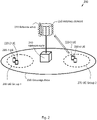
Figure 2 is a schematic illustration over awireless communication network 200 comprising anetwork node 210 and a number of User Equipment (UEs) 220-1, 220-2, 220-3, 220-4. Thenetwork node 210 comprises, or is connected to an access node having radio communication ability within acoverage area 230. Thenetwork node 210 also comprises, or is connected to anantenna array 240, comprising at least oneantenna element 250. In some embodiments, theantenna array 240 may be configured for MIMO, or massive MIMO communication. Massive MIMO is sometimes loosely defined as a system comprising 100 ormore antenna elements 250. Advantages with massive MIMO comprise e.g. improved UE detection, reduced transmit power per UE 220-1, 220-2, 220-3, 220-4, and higher aggregate rate thanks to a high spatial resolution of massive MIMO. - The
wireless communication network 200 may at least partly be based on, or inspired by, radio access technologies such as, e.g., 3GPP LTE, LTE-Advanced, Evolved Universal Terrestrial Radio Access Network (E-UTRAN), Universal Mobile Telecommunications System (UMTS), just to mention some few options. - The expressions "wireless communication network", "wireless communication system" and/ or "cellular telecommunication system" may within the technological context of this disclosure sometimes be utilised interchangeably.
- The
wireless communication network 200 may be configured to operate according to the Time Division Duplex (TDD) principle and in the subsequent description and associated figures, embodiments will be consequently described in a TDD environment. However, some embodiments may be based on, or implemented in a Frequency Division Duplex (FDD) environment. - TDD is an application of time-division multiplexing to separate uplink and downlink signals in time, possibly with a Guard Period (GP) situated in the time domain between the uplink and downlink signalling and/ or between the pilot region and data region. FDD means that the transmitter and receiver operate at different carrier frequencies.
- The purpose of the illustration in
Figure 2 is to provide a simplified, general overview of thewireless communication network 200 and the involved methods and nodes, such as thenetwork node 210 and UEs 220-1, 220-2, 220-3, 220-4 herein described, and the functionalities involved. Further, a new multiple-access technique is presented that enables to schedule more UEs 220-1, 220-2, 220-3, 220-4 for uplink transmission over shared channels as compared with conventional solutions that utilise orthogonal pilot transmission in a cell, as illustrated inFigure 1A . Thereby, the spectrally efficiency for MIMO and in particular massive MIMO communications is improved. The solution may be regarded as generalisation of the previously described SOMA and may hence be referred to as Generalised SOMA (GSOMA) subsequently, but without the disadvantages associated with SOMA as subsequently will be further explained. - More specifically, embodiments herein describes a method for communication of multiple data packets originated from multiple UEs 220-1, 220-2, 220-3, 220-4 such that the UEs 220-1, 220-2, 220-3, 220-4 are grouped such that some UEs 220-1, 220-2 are grouped in a
first UE group 260 and some other UEs 220-3, 220-4 are grouped in asecond UE group 270. - The UEs 220-1, 220-2, 220-3, 220-4 within each
group same group different groups UE group - GSOMA comprises both the SOMA scheme and the conventional TDD solution as special cases. When each
group - In some embodiments the data packets within each
UE group group - In another embodiment of the solution, the
UE group system 200. In yet another embodiment UE grouping may be performed in the network level where thegroups - It is to be noted that the illustrated network setting of one
network node 210, four UEs 220-1, 220-2, 220-3, 220-4 and twoUE groups Figure 2 is to be regarded as a nonlimiting example of an embodiment only. Thewireless communication network 200 may comprise any other number and/ or combination ofnetwork nodes 210 and/ or UEs 220-1, 220-2, 220-3, 220-4. Any other arbitrary plurality of UEs 220-1, 220-2, 220-3, 220-4,UE groups network nodes 210 may thus be involved in some embodiments of the disclosed invention. - The
network node 210 may according to some embodiments be configured for downlink transmission and uplink reception may be referred to, respectively, as e.g., a base station, NodeB, evolved Node Bs (eNB, or eNode B), base transceiver station, Access Point Base Station, base station router, Radio Base Station (RBS), micro base station, pico base station, femto base station, Home eNodeB, sensor, beacon device, relay node, repeater or any other network node configured for communication with the UEs 220-1, 220-2, 220-3, 220-4 over a wireless interface, depending, e.g., of the radio access technology and/ or terminology used. - The UEs 220-1, 220-2, 220-3, 220-4 may correspondingly be represented by, e.g. a wireless communication terminal, a mobile cellular phone, a Personal Digital Assistant (PDA), a wireless platform, a mobile station, a tablet computer, a portable communication device, a laptop, a computer, a wireless terminal acting as a relay, a relay node, a mobile relay, a Customer Premises Equipment (CPE), a Fixed Wireless Access (FWA) nodes or any other kind of device configured to communicate wirelessly with the
network node 210, according to different embodiments and different vocabulary. - An example of an embodiment will subsequently be described. In such embodiment, the UEs 220-1, 220-2, 220-3, 220-4 are grouped into J groups where each group j contains kj UEs 220-1, 220-2, 220-3, 220-4 for j ∈ {1,2, ...,J} where

Figure 2 for an illustration. The UE i in UE group j ∈ {1,2, ...,J} uses the pilot sequences si . That is the pilot sequences are reused. The pilot sequences within eachUE group UE group - Conventional reuse of pilot sequences where the pilot sequences interference with one another results in "pilot contaminations" which severely degrades the performance of the UEs 220-1, 220-2, 220-3, 220-4. However with this new solution, it is allowed to reuse the pilot sequences in a controlled fashion. A pilot reuse is performed non-orthogonally to boost the spectral efficiency of the
system 200. However, the interference may be controlled by a transmission of a resource-offset such as for example timing-offset or frequency-offset. Thus, the pilot sequences ofdifferent UE groups first UE group 260 are received interference-free. That is the other UEs 220-1, 220-2 grouped in thefirst UE group 260 appear silent at the receiver side. The pilot sequences of UE group j ∈ {1,2, ...,J}, are only interfered by data symbols ofUEs 1 to j - 1. -
Figure 3 illustrates an embodiment comprising multiple-access with user grouping for pilot reuse and resource-offset transmission. The time axis indicates the reception time at the receiver side. In some embodiments of the solution, the UEs 220-1, 220-2, 220-3, 220-4 may use partial blanking to control to the quality channel estimation at the receiver side as illustrated inFigure 3 . - The disclosed structure allows reusing the pilot sequences because it avoids pilot contaminations. So for example, if a time interval of length Tp is used for pilot and the total transmission for each subframe is Tc = Td+Tp , where Td is a transmission time for data, Tc is the coherence time. Then the maximum number of
UE groups 
- To illustrate the ultimate impact of the disclosed method, consider the case of an
access node 210 with anantenna array 240 with very high number ofantenna elements 250. For this case, the conventional solution allocates half of the time for training and the remaining time for data transmission in order to maximise the aggregate rate. That is the total number of symbols nsym that can be asymptotically with a negligible error can be detected as the number of antennas increases, is given by:
- However, with the new solution according to equation (7), two
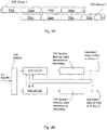
UE groups Figure 4A illustrates an example of this case with twoUE groups different UE groups first UE group 260, the associated channels are estimated and then the followed data is decoded. The decoded data of thefirst UE group 260 is fed to the channel estimator subtracted the interference due to the data symbols for the pilots of thesecond UE group 270. The procedure is then continued iteratively. For large number ofantennas 250, it can be shown that the number of recovered symbols

antennas 250, which will be discussed subsequently. - For multicarrier system, equation (8) and equation (9) will respectively change to


-
Figure 4B illustrates an example of a receiver utilised e.g. in the two UE group case illustrated inFigure 4A . - For the case the
antenna array 240 comprises not somany antenna elements 250, it may be beneficial to partially blank some part of subframes to enhance the channel estimation and to improve consequently the performance of spatial filtering which in turn enhances the spectral efficiency of the system.Figure 5 depicts an example. The blanking pattern, may be chosen based on the inter-UE interference when for higher interference a blanking pattern with a higher density may be considered and also for lower interference, a sparser blanking pattern may be selected to improve the spectral efficiency of thesystem 200, in some embodiments. - The quality of channel estimation quality plays a key role on the performance of the
system 200. One way to optimise the performance of thesystem 200 is to perform closed loop power control where the power control is done based on the uplink pilot symbol. For the disclosed construction it is desirable that to have variable average power allocation on the pilot and the data symbols where the power allocation varies overdifferent groups Figure 4B andFigure 5 , it may be desirable to have higher power allocation on the pilot sequences of the UEs 220-1, 220-2 in thefirst UE group 260 to allows a higher quality channel estimation which enables an improved detection of the data symbols of thefirst UE group 260 and also better interference cancellation on the pilot sequences. Note that that in order to perform interference cancellation on the pilot sequences of bothUE groups - In another embodiment, the resource-offset may compromise frequency-offset such that the same principle with the time-offset can be accomplished in frequency domain. That is the resource on the horizontal axis in
Figure 3 is frequency. Thus the grouping for the case of joint time- and frequency-offset can be computed as:
- The main solution in
Figure 3 is constructed by grouping the UEs 220-1, 220-2, 220-3, 220-4. The UE grouping in some scenarios can be done based on the association of UEs 220-1, 220-2, 220-3, 220-4 to cells. The following embodiment of the UE grouping in the main solution is done in the network-level where the UE grouping may amount to a Virtual Heterogeneous Network (vHetNet) as illustrated inFigure 6A . The reason for virtual HetNet is to avoid backhaul deployments as compared to the conventional deployment. In this example, avirtual pico cell 410 and amacro cell 230 are provided, however, other set-ups may comprise another number ofvirtual pico cells 410. - An example of the solution is given in
Figure 6B . The disclosed solution may be necessary as for uplink transmission the pilot sequences from the virtual Pico-cells 410 and theMacro cell 230 will interfere with one another. The transmitted uplink reference signals from the Pico cell UEs 220-3, 220-4 and Macro cell UEs 220-1, 220-2 interfere with one another. Hence, the constructed directional beams leak to unwanted UEs due to the pilot contaminations. For the case when thevirtual Pico cell 410 andMacro cells 230 have different antenna hardware, a Coordinated Multi-Point (CoMP) transmission can be simply adopted as the associated base stations are collocated. - Hence the receiver in
Figure 6A can be implemented when thefirst UE group 260 comprises Macro cell UEs 220-1, 220-2 and thesecond UE group 270 comprises Pico cell UEs 220-3, 220-4. - Further, the aggregate-rate of the scheme over Rayleigh fading radio channels whose coherence time is Tc, i.e. the number of symbols for which the channel approximately remains unchanged, may be considered. It is assumed that the average channel gain from each UE 220-1, 220-2, 220-3, 220-4 to the
antenna array 240 attached to theaccess node 210 is normalised to one. The following three solutions are considered and subsequently discussed: a) conventional TDD, b) SOMA, and c) GSOMA with time-offset and partial blanking. - For Conventional TDD, consider the baseline solution using the conventional TDD solution protocol where the number of UEs 220-1, 220-2, 220-3, 220-4 is set to half of the coherence time. The conventional TDD solution with Matched Filtering (MF) and MMSE channel estimation achieves the sum-rate:

- Using Zero-Forcing (ZF) for spatial filtering and MMSE channel estimation, one can prove the following holds


- Finally, an embodiment comprising GSOMA with Time-offset and Blanking may be discussed. Consider the transmission protocol illustrated in
Figure 5 wherein the uplink transmission with multiple subframes is considered. There are twoUE groups UE group 
UE group second UE group 270 are completely reused by the UEs 220-3, 220-4 of thesecond UE group 270. The UEs 220-1, 220-2, 220-3, 220-4 employ partial blanking, which the blanking pattern is signalled by theaccess node 210, and it is designed such the pilots of the first group do not receive any interference at all and the channel estimation for the UEs 220-1, 220-2 in thefirst UE group 260 does not degrade with respect to the baseline. The blanking pattern in this example has the granularity of half of the subframe length which is equal to the portion of pilot region. However the pilot sequences of thesecond UE group 270 are concurrently received as the data of thefirst UE group 260. The disclosed embodiment according toFigure 5 , with MF for spatial filtering and MMSE channel estimation achieves the sum-rate:


- Subsequently, a proof of the sum-rate with MF will be outlined to further clarify some aspects of the described embodiments of the solution. In this example, there are two
UE groups first UE group 260 are mutually orthogonal hence the receiver can perform channel estimation for each UE 220-1, 220-2 in theUE group 260 independently and without interference. Without loss of generality, consider the first UE 220-1 in thefirst UE group 260. Then the received pilot sequence is given by:
first UE group 260 to theantenna array 240 with nt antenna elements 250, and x p11 is the pilot symbol transmitted from the first UE 220-1 in thefirst UE group 260 and z p1 is the AWGN noise vector with nt antenna elements 250 at theantenna array 240. Over the first time-frequency resource element the other UEs 220-2 are silent and the first channel estimator can estimate the channel vector h 11 without any interference. The estimated channel vector can be written as ĥ 11 = h 11 + z e11 , where z e11 denotes the channel estimation error vector. With the MMSE channel estimation, each element of the channel estimation error vector has the variance equal to
first UE group 260. - The received data signal over ith time-frequency resource element is given by:

- Where h ij denotes the channel vector of UE i of group j, x dj1,i denotes the data symbol transmitted from UE j in the
first UE group 260 over the ith time-frequency resource element, j = 1,2,..., k and xpi2 denotes the pilot of the 220-3, 220-4 of thesecond UE group 270 that is transmitted in ith time-frequency resource element and z i denotes AWGN at the receiver for ith time-frequency resource element. Next the receiver using the estimated channel vector of the first user, ĥ 11 = h 11 + z e11 , where z e11 is channel estimation error, obtained via the signal vector y p1 , can perform the normalised matched filtering for 2 ≤ i ≤ N, as follows:

first UE group 260, the following sum-rate for the first group becomes achievable:
- Further, the
second UE group 270 may be considered. The receiver first needs to estimate the channel of the UEs 220-3, 220-4 of thesecond UE group 270. The UEs 220-3, 220-4 in thesecond UE group 270 transmit the corresponding pilot sequences concurrently with the data symbols of all UEs 220-1, 220-2 in thefirst UE group 260. Consider the received signal:
second UE group 270. The received noisy pilot sequence associated the corresponding UE 220-3 is interfered by the data symbols x dj1,i for allUEs 1 ≤ j ≤ K in thefirst UE group 260. However these data symbols are previously decoded and the associated channels are also estimated as ĥ j1. Thus the receiver can perform an interference cancellation as follows to obtain the processed signal ỹ i:
- The estimated channel vector obtained via ỹ t can be written as ĥ i2 = h i2 + z e
i2 , where z ei2 denotes the channel estimation error vector. With the MMSE channel estimation, each element of the channel estimation error vector has the variance equal to:
second UE group 270. Now using the estimated channels ĥ i2, the receiver performs MF filtering for the signals that carry the information of the UE 220-3, 220-4 in thesecond UE group 270. Toward this end, consider the first UE 220-3 in thesecond UE group 270. The received data over ith time-frequency resource element is given by:
second UE group 270 over the ith time-frequency resource element. Next the receiver using the estimated channel vector, ĥ 12 = h 12 + z e12, of the first UE 220-3 in thesecond UE group 270 performs the normalised matched filtering as follows to obtain the processed signal ỹ i :
- Note that the desired variable || ĥ 11||x d11,i is uncorrelated to the remaining terms in (28). Hence, by using the fact that the worst uncorrelated noise is Gaussian, and repeating this procedure for all UEs 220-3, 220-4 in the
second UE group 270, then the following rate becomes achievable:
- Where Rk2 denotes the transmission rate of user k in the second group, the first inequality similarly follows by Jensen inequality and the last equality holds because of the properties of inverse-Wishart distribution. Now the summation of the rates of all UEs 220-1, 220-2, 220-3, 220-4 in both
UE groups 
- Furthermore, a proof of the sum-rate obtained by ZF will be outlined. There are two
UE groups first UE group 260 are orthogonal so the receiver can estimate the channels of all UEs 220-1, 220-2 prior to the spatial filtering. The estimated channels can be written in a matrix according as:
first UE group 260 to the antenna array. Using the estimated channel matrix Ĥ 1, the receiver forms the zero-forcing matrix given as:
- Using the constructed spatial filter W ZF, the receiver obtains the signal vector:

- From equation (33), it is seen that the spatial ZF filtering orthogonalises (i.e. zero-forces) the interference of the other UEs 220-1, 220-2, 220-3, 220-4. Considering the first element of ỹ i

- Again it may be noted that || ŵ 11||x d11,i is uncorrelated with the remaining variables in equation (34). Then evoking the fact that the worst uncorrelated noise is Gaussian, the following rate is achievable:


- Further, the
second UE group 270 may be considered. The receiver first estimates all channels of the UEs 220-3, 220-4 of thesecond UE group 270. This can be done in a similar fashion as has already been illustrated in the previous example, using the same interference cancellation procedure as described in equation (25). Having estimated channels of all UEs 220-3, 220-4 in thesecond UE group 270, the receiver then performs ZF using the estimated channel vectors. By following the same procedure as that for thefirst UE group 260 outlined in equations (31)-(35), the sum-rate for thesecond UE group 270 is given by:

- Finally, the sum-rate of all UEs 220-1, 220-2, 220-3, 220-4 in both
UE groups 
-
Figure 7 illustrates yet a Hetnet scenario, similar to the virtual Hetnet depicted inFigure 6A . However, thesystem 200 here comprises apico node 710, forming apico cell 720. Thepico node 710 is connected to thenetwork node 210 via a backhaul link, which may be wired or wireless in different embodiments. However, other set-ups may comprise another number ofpico nodes 710 andpico cells 720. - In some embodiments, UEs 220-1, 220-2 situated in the
macro cell 230, served bynetwork node 210 may be grouped together in one group, e.g. thefirst UE group 260 while UEs 220-3, 220-4 served by thepico node 710 may be grouped in thesecond group 250 etc.Figure 8 is a flow chart illustrating embodiments of amethod 800 innetwork node 210. Themethod 800 concerns wireless communication with a plurality of UEs 220-1, 220-2, 220-3, 220-4 in awireless communication system 200, wherein the UEs 220-1, 220-2, 220-3, 220-4 are grouped together in at least twoUE groups network node 210 comprises, or is connectable to; a plurality ofantenna elements 250, forming amultiple antenna array 240 which may be configured for massive Multiple-Input Multiple-Output (MIMO) transmission. - The
multiple antenna array 240 comprises a multitude ofantenna elements 250, such as e.g. hundred ormore antenna elements 250 in some embodiments. Thewireless communication system 200 thus may be configured for massive MIMO, according to some embodiments. The multitude of antenna elements may in some embodiments be mounted at a distance from each other, within themultiple antenna array 240, such that some, several or even all of theantenna elements 250 may be able to receive/ transmit the same signal from/ to the UEs 220-1, 220-2, 220-3, 220-4. - The
wireless communication network 200 may be based on 3GPP LTE. Further, thewireless communication system 200 may be based on FDD or TDD in different embodiments. Thenetwork node 210 may comprise an eNodeB according to some embodiments. - To appropriately communicate with the UEs 220-1, 220-2, 220-3, 220-4, the
method 500 may comprise a number of actions 801-813. - It is however to be noted that any, some or all of the described actions 801-813, may be performed in a somewhat different chronological order than the enumeration indicates, be performed simultaneously or even be performed in a completely reversed order according to different embodiments. Some of the actions 801-813, such as the actions 806-813 may be performed only in some alternative embodiments. Further, it is to be noted that some actions may be performed in a plurality of alternative manners according to different embodiments, and that some such alternative manners may be performed only within some, but not necessarily all embodiments. The
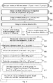
method 800 may comprise the following actions: - A plurality of UEs 220-1, 220-2, 220-3, 220-4 are grouped into at least a
first UE group 260 and asecond UE group 270. - The total number of UEs 220-1, 220-2, 220-3, 220-4 may be any arbitrary integer > 1. Also the number of
UE groups UE groups - The grouping of the plurality of UEs 220-1, 220-2, 220-3, 220-4 into any of at least a
first UE group 260 and asecond UE group 270, may in some embodiments be based on cell location of each UE 220-1, 220-2, 220-3, 220-4. - In some embodiments, the UEs 220-1, 220-2 situated within a
Macro cell 230 may be grouped in thefirst UE group 260, and UEs 220-3, 220-4 situated within avirtual Pico cell 410 may be grouped in thesecond UE group 270. - Furthermore, the grouping of the UEs 220-1, 220-2, 220-3, 220-4, based on received signal strength, wherein UEs 220-1, 220-2, 220-3, 220-4 associated with a received signal strength lower than a threshold value may be grouped in the
first UE group 260 while UEs 220-1, 220-2, 220-3, 220-4 associated with a received signal strength exceeding the threshold value may be grouped in thesecond UE group 270. - A mutually orthogonal pilot sequence is assigned to each UE 220-1, 220-2 comprised in the
first UE group 260. - Pilot sequences of mutually orthogonal pilot sequences may be assigned to the UEs 220-1, 220-2 grouped 801 in the
first UE group 260 which are reusable by UEs 220-3, 220-4 grouped 801 in thesecond UE group 270 in some embodiments. - A mutually orthogonal pilot sequence is assigned to each UE 220-3, 220-4 comprised in the
second UE group 270. - Pilot sequences of mutually orthogonal pilot sequences may be assigned to the UEs 220-3, 220-4 grouped 801 in the
second UE group 270, which are reusable by UEs 220-1, 220-2 in thefirst UE group 260. - A resource-offset is assigned to the UEs 220-1, 220-2, 220-3, 220-4 comprised in each
UE group - The first resource-offset sequences may be selected such that the received pilot sequences of UEs 220-1, 220-2 in the
first UE group 260 are not interfered by signals transmitted from the UEs 220-3, 220-4 in thesecond UE group 270 while the pilot sequences of UEs 220-3, 220-4 in thesecond UE group 270 are received concurrently with the data of the UEs 220-1, 220-2 in thefirst UE group 260 and any other pilot sequence which is orthogonal to the pilot sequences of the UEs 220-3, 220-4 in thesecond UE group 270, in some embodiments. - The assigned 802, 803 pilot sequences and the assigned 804 resource-offset are transmitted to UEs 220-1, 220-2, 220-3, 220-4.
- This action may be performed only in some alternative embodiments.
- A partial blanking pattern sequence may be transmitted to UEs 220-1, 220-2, 220-3, 220-4 comprised in at least one of the
UE groups - The partial blanking pattern of the UEs 220-1, 220-2 in the
first UE group 260 may have a granularity equal to the portion of the pilot region of UEs 220-3, 220-4 comprised inother UE groups 270, for reducing interference among the pilot and data sequences, and vice versa. - This action may be performed only in some alternative embodiments.
- Pilot sequences and data sequences may be received from the UEs 220-1, 220-2, 220-3, 220-4 in the
respective UE groups - Pilot sequences and/ or data sequences may be received from the UEs 220-1, 220-2, 220-3, 220-4 in the
respective UE groups - This action may be performed only in some alternative embodiments.
- A channel of each UE 220-1, 220-2 in the
first UE group 260 may be estimated. - A respective channel of each UE 220-1, 220-2 in the
first UE group 260 may be estimated, based on the received 805 orthogonal pilot sequences from UEs 220-1, 220-2 in thefirst UE group 260. - This action may be performed only in some alternative embodiments.
- Data sequences of the UEs 220-1, 220-2 in the
first UE group 260 may be detected. - Data sequences of the UEs 220-1, 220-2 in the
first UE group 260 may be detected, which may be used to cancel interference over the received 805 pilot sequences of UEs 220-3, 220-4 in thesecond UE group 270. - This action may be performed only in some alternative embodiments.
- A channel of each UE 220-3, 220-4 in the
second UE group 270 may be estimated. - This action may be performed only in some alternative embodiments.
- Data sequences of the UEs 220-3, 220-4 in the
second UE group 270 may be detected. - The data sequences of the UEs 220-3, 220-4 in the
second UE group 270 may be detected, which may be used to cancel interference over the received 805 pilot sequences ofUEs 220 in thefirst UE group 260. - This action may be performed only in some alternative embodiments.
- Use data sequences of UEs 220-3, 220-4 in the
second UE group 270 to cancel interference over received pilot sequences from the UEs 220-1, 220-2 in thefirst UE group 260, and vice versa, i.e. data sequences of the UEs 220-1, 220-2 in thefirst UE group 260 may be used to cancel interference over the received 805 pilot sequences of UEs 220-3, 220-4 in thesecond UE group 270. - This action may be performed before
action 810 in some embodiments. - This action may be performed only in some alternative embodiments.
- The UEs 220-1, 220-2, 220-3, 220-4 may be instructed to adjust transmission power, based on the inter-group interference between the pilot and data symbol sequences and quality of the channel estimation.
- Further, some embodiments may comprise updating the
grouping 801, the assigned 802, 803 pilot sequences, the assigned 804 resource-offset sequences or the transmitted 806 partial blanking pattern sequences, which may be signalled to the UEs 220-1, 220-2, 220-3, 220-4, based on UE mobility, channel conditions, active number of UEs within range and transmission load. - Some embodiments may comprise coordinating reception and transmission at a plurality of
access nodes 710, associated with thenetwork node 210 in Coordinated Multi-Point (CoMP) transmissions. -
Figure 9 illustrates an embodiment of anetwork node 210, configured for wireless communication with UEs 220-1, 220-2, 220-3, 220-4 in awireless communication system 200. - The
network node 210 is configured for performing themethod 800, according to any, some, all, or at least one of the enumerated actions 801-813, according to some embodiments. Thus thenetwork node 210 is configured to receive data from a plurality of UEs 220-1, 220-2, 220-3, 220-4 over a plurality of shared time-frequency resources. Thenetwork node 210 may be connected to anantenna array 240 with at least oneactive antenna element 250. However, in some embodiments, theantenna array 240 may comprise a plurality ofantenna elements 250, such as tens, or hundreds ofantenna elements 250. - The
network node 210 may according to some embodiments comprise an evolved NodeB, eNodeB. Thewireless communication network 200 may optionally be based on 3rd Generation Partnership Project Long Term Evolution, 3GPP LTE. - The
network node 210 comprises aprocessing unit 920. Theprocessing unit 920 is configured to group a plurality of UEs 220-1, 220-2, 220-3, 220-4 into at least afirst UE group 260 and asecond UE group 270. Theprocessing unit 920 is further configured to assign a mutually orthogonal pilot sequence to each UE 220-1, 220-2 comprised in thefirst UE group 260. In addition, theprocessing unit 920 is configured to assign a mutually orthogonal pilot sequence to each UE 220-3, 220-4 comprised in thesecond UE group 270. Also, theprocessing unit 920 is furthermore additionally configured to assign a resource-offset to the UEs 220-1, 220-2, 220-3, 220-4 comprised in eachUE group - The
processing unit 920 may be further configured to assign the resource-offset such that the pilot sequences of the UEs 220-1, 220-2 in thefirst UE group 260 are not interfered by the pilot sequences of the UEs 220-3, 220-4 in thesecond UE group 270, in some embodiments. - Further, the
processing unit 920 may be further configured to assign and transmit a partial blanking pattern sequence to UEs 220-1, 220-2 comprised in at least one of theUE groups 260, wherein the partial blanking pattern sequence may have a granularity equal to granularity of the pilot sequences of UEs 220-3, 220-4 comprised inother UE groups 270, for reducing the interference among theUE groups - The
processing unit 920 may also be further configured to update the grouping of UEs 220-1, 220-2, 220-3, 220-4, the assigning of pilot sequences, the assigning of resource-offset sequences or the assigning of partial blanking pattern sequences, based on UE mobility, channel conditions, active number of UEs within range and/ or transmission load. - The
processing unit 920 may furthermore be configured to group the plurality of UEs 220-1, 220-2, 220-3, 220-4 into at least thefirst UE group 260 and thesecond UE group 270, based on cell location of each UE 220-1, 220-2, 220-3, 220-4 in some embodiments. - Furthermore, the
processing unit 920 may also be configured to group the UEs 220-1, 220-2 situated within aMacro cell 230 into thefirst UE group 260, and to group the UEs 220-3, 220-4 situated within avirtual Pico cell 410 into thesecond UE group 270. - The
processing unit 920 may furthermore be configured to group the UEs 220-1, 220-2, 220-3, 220-4, based on Channel Quality Index (CQI) wherein UEs 220-1, 220-2, 220-3, 220-4 associated with a CQI lower than a threshold value are grouped in thefirst UE group 260. - The
processing unit 920 may be further configured to coordinate reception and transmission at a plurality ofaccess nodes 710, associated with thenetwork node 210 in CoMP transmissions. - The
processing unit 920 may also be further configured to estimate a channel of each UE 220-1, 220-2 in thefirst UE group 260, based on the received mutually orthogonal pilot sequences of UEs 220-1, 220-2 grouped in thefirst UE group 260 in some embodiments. - Also, the
processing unit 920 may be further configured to detect the data sequences of the UEs 220-1, 220-2 in thefirst UE group 260, which data sequences are used to cancel interference over received pilot sequences of UEs 220-3, 220-4 grouped in thesecond UE group 270. - The
processing unit 920 may be further configured to estimate a channel of each UE 220-3, 220-4 in thesecond UE group 270, based on the received mutually orthogonal pilot sequences of UEs 220-3, 220-4 grouped in thesecond UE group 270. - Further, the
processing unit 920 may be further configured to detect the data sequences of the UEs 220-3, 220-4 in thesecond UE group 270, wherein the data sequences may be used to cancel interference over the received pilot sequences from UEs 220-1, 220-2 grouped in thefirst UE group 260. - The
processing unit 920 may in some embodiments be further configured to sequentially continue the channel estimation and data detection process, iteratively. - Also, the
processing unit 920 may be further configured to instruct at least one UE 220-1, 220-2, 220-3, 220-4 to adjust transmission power, based on at least one of: the channel estimation of eachUE group UE groups -
Such processing unit 920 may comprise one or more instances of a processing circuit, i.e. a Central Processing Unit (CPU), a processing unit, a processing circuit, a processor, an Application Specific Integrated Circuit (ASIC), a microprocessor, or other processing logic that may interpret and execute instructions. The herein utilised expression "processing unit" may thus represent a processing circuitry comprising a plurality of processing circuits, such as, e.g., any, some or all of the ones enumerated above. - Furthermore, the
network node 210 comprises atransmitter 930 configured to transmit the pilot sequences and the resource-offset and possibly also other wireless signals to UEs 220-1, 220-2, 220-3, 220-4. - Further the
network node 210 may in addition comprise areceiver 910 configured to receive the mutually orthogonal pilot sequences and data sequences from the UEs 220-1, 220-2 grouped in thefirst UE group 260 and to receive the mutually orthogonal pilot sequences and data sequences from the UEs 220-3, 220-4 grouped in thesecond UE group 270, in some embodiments. - Furthermore, the
network node 210 may comprise at least onememory 925, according to some embodiments. Theoptional memory 925 may comprise a physical device utilised to store data or programs, i.e., sequences of instructions, on a temporary or permanent basis. According to some embodiments, thememory 925 may comprise integrated circuits comprising silicon-based transistors. Further, thememory 925 may be volatile or non-volatile. - The actions 801-813 to be performed in the
network node 210 may be implemented through the one ormore processing circuits 920 in thenetwork node 210, together with computer program product for performing the functions of the actions 801-813. Thus a computer program product, comprising instructions for performing the actions 801-813 in thenetwork node 210 may perform wireless communication with UEs 220-1, 220-2, 220-3, 220-4 in awireless communication system 200 in antenna streams, when the computer program product is loaded in aprocessing circuit 920 of thenetwork node 210. - Thus a computer program comprising program code for performing the
method 800 according to any of the actions 801-813, may perform wireless communication with UEs 220-1, 220-2, 220-3, 220-4 in awireless communication system 200, when the computer program is loaded into aprocessor 920 of the network node 110. - Thereby a computer program product may comprise a computer readable storage medium storing program code thereon for use by a
network node 210, for wireless communication with UEs 220-1, 220-2, 220-3, 220-4 in awireless communication system 200. The program code comprising instructions for executing amethod 800 comprising: grouping 801 a plurality of UEs 220-1, 220-2, 220-3, 220-4 into at least afirst UE group 260 and asecond UE group 270; assigning 802 a mutually orthogonal pilot sequence to each UE 220-1, 220-2 comprised in thefirst UE group 260; assigning 803 a mutually orthogonal pilot sequence to each UE 220-3, 220-4 comprised in thesecond UE group 270; assigning 804 a resource-offset to the UEs 220-1, 220-2, 220-3, 220-4 comprised in eachUE group - The computer program product mentioned above may be provided for instance in the form of a data carrier carrying computer program code for performing at least some of the actions 801-813 according to some embodiments when being loaded into the
processing circuit 920. The data carrier may be, e.g., a hard disk, a CD ROM disc, a memory stick, an optical storage device, a magnetic storage device or any other appropriate medium such as a disk or tape that may hold machine readable data in a non-transitory manner. The computer program product may furthermore be provided as computer program code on a server and downloaded to thenetwork node 210 remotely, e.g., over an Internet or an intranet connection. -
Figure 10 shows the evaluation results for the coherence time Tc = 10, and Rayleigh fading channels where


first UE group 260 is increased to improve the channel estimation to be used for interference cancellation on the pilot of the UEs 220-3, 220-4 in thesecond group 270.Figure 10 plots the average rate obtained by simulating 5000 random channels and computing the associated average rate after MF and ZF, which are shown by square and diamonds respectively. The analytical bounds in equations (11)-(16) are plotted with dashed and solid lines for MF and ZF respectively. For the sum-rate 15 [bit/s/Hz], by setting the spatial filtering to be ZF, the conventional TDD demands for more than 700 antennas while the new solution requires nearly 200 antennas as compared to the conventional solution, which is a significant reduction. For SOMA, in order to achieve the same rate requires nearly 450 antennas. For 200 and 400 antennas, the gain in throughput with respect to the conventional TDD amounts to nearly 43% and 40%, respectively, and the gain with respect to SOMA amount to nearly 40% and 25%, respectively. Theantenna array 240 can collect the energy over multiple paths and hence theaccess node 210 is capable to recover the noisy received signal in spite of the fact the data power is very low. This hence advocates the use of massiveMIMO antenna arrays 240 for establishment of energy-efficient communication systems 200. - Some embodiments of the disclosed
method 800 may be applicable insystems 200 combined with multi-carrier modulations, such as OFDM transmission. - The terminology used in the description of the embodiments as illustrated in the accompanying drawings is not intended to be limiting of the described
method 800 and/ ornetwork node 210. Various changes, substitutions and/ or alterations may be made, without departing from the invention as defined by the appended claims. - As used herein, the term "and/ or" comprises any and all combinations of one or more of the associated listed items. The term "or" as used herein, is to be interpreted as a mathematical OR, i.e., as an inclusive disjunction; not as a mathematical exclusive OR (XOR), unless expressly stated otherwise. In addition, the singular forms "a", "an" and "the" are to be interpreted as "at least one", thus also possibly comprising a plurality of entities of the same kind, unless expressly stated otherwise. It will be further understood that the terms "includes", "comprises", "including" and/ or "comprising", specifies the presence of stated features, actions, integers, steps, operations, elements, and/ or components, but do not preclude the presence or addition of one or more other features, actions, integers, steps, operations, elements, components, and/ or groups thereof. A single unit such as e.g. a processor may fulfil the functions of several items recited in the claims. The mere fact that certain measures are recited in mutually different dependent claims does not indicate that a combination of these measures cannot be used to advantage. A computer program may be stored/ distributed on a suitable medium, such as an optical storage medium or a solid-state medium supplied together with or as part of other hardware, but may also be distributed in other forms such as via Internet or other wired or wireless communication system.
Claims (14)
- A network node (210), comprising:a processing unit (920) configured to:group a plurality of UEs (220-1, 220-2, 220-3, 220-4) into at least a first UE group (260) and a second UE group (270);assign a mutually orthogonal pilot sequence to each UE (220-1, 220-2) comprised in the first UE group (260);assign a mutually orthogonal pilot sequence to each UE (220-3, 220-4) comprised in the second UE group (270); andassign a resource-offset to each of the UEs (220-1, 220-2, 220-3, 220-4) comprised in each UE group (260, 270), by which each UE (220-1, 220-2, 220-3, 220-4) is allowed to start its transmission sub-frame in its Transmission Time Interval, TTI, wherein the resource offset comprises a time offset ora frequency offset; anda transmitter (930) configured to transmit a pilot sequence index and the resource-offset to each UE (220-1, 220-2, 220-3, 220-4);
wherein the processing unit (920) is further configured to assign and transmit a partial blanking pattern sequence to the UEs (220-1, 220-2) comprised in at least one of the UE groups (260). - The network node (210) according to claim 1, wherein the processing unit (920) is further configured to assign the resource-offset such that the pilot sequences of the UEs (220-1, 220-2) in the first UE group (260) are not interfered by the pilot sequences of the UEs (220-3, 220-4) in the second UE group (270).
- The network node (210) according to claim 1 or 2, wherein the partial blanking pattern of the UEs (220-1, 220-2) in the at least one of the UE group (260) has a granularity equal to a portion of a pilot region of UEs (220-3, 220-4) comprised in other UE groups (270).
- The network node (210) according to any of claims 1-3, wherein the processing unit (920) is configured to group the plurality of UEs (220-1, 220-2, 220-3, 220-4) into at least the first UE group (260) and the second UE group (270), based on cell location of each UE (220-1, 220-2, 220-3, 220-4).
- The network node (210) according to any of the proceeding claims, further comprising a receiver (910) configured to receive the mutually orthogonal pilot sequences and data sequences from the UEs (220-1, 220-2) grouped in the first UE group (260) and to receive the mutually orthogonal pilot sequences and data sequences from the UEs (220-3, 220-4) grouped in the second UE group (270).
- A method (800) in a network node (210), comprising:grouping (801) a plurality of UEs (220-1, 220-2, 220-3, 220-4) into at least a first UE group (260) and a second UE group (270);assigning (802) a mutually orthogonal pilot sequence to each UE (220-1, 220-2) comprised in the first UE group (260);assigning (803) a mutually orthogonal pilot sequence to each UE (220-3, 220-4) comprised in the second UE group (270);assigning (804) a resource-offset to each of the UEs (220-1, 220-2, 220-3, 220-4) comprised in each UE group (260, 270), by which each UE (220-1, 220-2, 220-3, 220-4) is allowed to start its transmission sub-frame in its Transmission Time Interval, TTI, wherein the resource offset comprises a time offset or a frequency offset; andtransmitting (805)a pilot sequence index and the assigned (804) resource-offset to each UE (220-1, 220-2, 220-3, 220-4);wherein the method further comprises assigning and transmitting a partial blanking pattern sequence to UEs (220-1, 220-2) comprised in at least one of the UE groups (260)..
- The method according to claim 6, further comprising assigning the resource-offset such that the pilot sequences of the UEs in the first UE group are not interfered by the pilot sequences of the UEs in the second UE group.
- The method according to claim 6 or 7, wherein the partial blanking pattern of the UEs (220-1, 220-2) in the at least one of the UE group (260) has a granularity equal to a portion of a pilot region of UEs (220-3, 220-4) comprised in other UE groups (270).
- The method according to any one of claims 6 -8, further comprising grouping the plurality of UEs (220-1, 220-2, 220-3, 220-4) into at least the first UE group (260) and the second UE group (270), based on cell location of each UE (220-1, 220-2, 220-3, 220-4).
- The method according to any one of claims 6 -9, further comprising receiving the mutually orthogonal pilot sequences and data sequences from the UEs grouped in the first UE group and receiving the mutually orthogonal pilot sequences and data sequences from the UEs grouped in the second UE group.
- A computer program comprising instructions which, when the program is executed by a computer, cause the computer to perform the method steps of any of claims 6 to 10.
- A UE (220-1, 220-2, 220-3, 220-4), which is in a UE group (260, 270) being configured and grouped by a network node (210) according to claim 1, the UE being configured to:receive, from said network node (210), a pilot sequence index and a resource-offset;transmit, to said network node (210), a pilot sequence and a data sequence wherein the pilot sequence is mutually orthogonal to pilot sequences of other UEs which are in the same UE group as the UE; andto further receive, from said network node (210), a partial blanking pattern sequence.
- The UE according to claim 12, wherein the partial blanking pattern of the UEs (220-1, 220-2) in the at least one of the UE group (260) has a granularity equal to a portion of a pilot region of UEs (220-3, 220-4) comprised in other UE groups (270).
- The UE according to claim 12 or claim 13, further being configured to adjust transmission power, based on channel estimation of the UE.
Applications Claiming Priority (3)
| Application Number | Priority Date | Filing Date | Title |
|---|---|---|---|
| PCT/EP2014/063286 WO2015197110A1 (en) | 2014-06-24 | 2014-06-24 | Method and apparatus for multiple access in a wireless communication system |
| PCT/EP2014/077138 WO2015197142A1 (en) | 2014-06-24 | 2014-12-10 | Method and node in a wireless communication network |
| EP14809414.7A EP3146664B1 (en) | 2014-06-24 | 2014-12-10 | Method and node in a wireless communication network |
Related Parent Applications (1)
| Application Number | Title | Priority Date | Filing Date |
|---|---|---|---|
| EP14809414.7A Division EP3146664B1 (en) | 2014-06-24 | 2014-12-10 | Method and node in a wireless communication network |
Publications (2)
| Publication Number | Publication Date |
|---|---|
| EP3629512A1 EP3629512A1 (en) | 2020-04-01 |
| EP3629512B1 true EP3629512B1 (en) | 2022-05-04 |
Family
ID=50982915
Family Applications (4)
| Application Number | Title | Priority Date | Filing Date |
|---|---|---|---|
| EP14732559.1A Active EP3152849B1 (en) | 2014-06-24 | 2014-06-24 | Method and apparatus for multiple access in a wireless communication system |
| EP18171670.5A Withdrawn EP3419201A1 (en) | 2014-06-24 | 2014-06-24 | Method and apparatus for multiple access in a wireless communication system |
| EP19202611.0A Active EP3629512B1 (en) | 2014-06-24 | 2014-12-10 | Method and node in a wireless communication network |
| EP14809414.7A Active EP3146664B1 (en) | 2014-06-24 | 2014-12-10 | Method and node in a wireless communication network |
Family Applications Before (2)
| Application Number | Title | Priority Date | Filing Date |
|---|---|---|---|
| EP14732559.1A Active EP3152849B1 (en) | 2014-06-24 | 2014-06-24 | Method and apparatus for multiple access in a wireless communication system |
| EP18171670.5A Withdrawn EP3419201A1 (en) | 2014-06-24 | 2014-06-24 | Method and apparatus for multiple access in a wireless communication system |
Family Applications After (1)
| Application Number | Title | Priority Date | Filing Date |
|---|---|---|---|
| EP14809414.7A Active EP3146664B1 (en) | 2014-06-24 | 2014-12-10 | Method and node in a wireless communication network |
Country Status (5)
| Country | Link |
|---|---|
| US (1) | US10270569B2 (en) |
| EP (4) | EP3152849B1 (en) |
| CN (2) | CN106664146B (en) |
| ES (1) | ES2764475T3 (en) |
| WO (2) | WO2015197110A1 (en) |
Families Citing this family (28)
| Publication number | Priority date | Publication date | Assignee | Title |
|---|---|---|---|---|
| EP3275108B1 (en) * | 2015-03-25 | 2021-11-17 | Telefonaktiebolaget LM Ericsson (publ) | Methods and devices for handling and assigning uplink pilots |
| CN111432486B (en) | 2015-05-08 | 2023-11-21 | 华为技术有限公司 | Apparatus and method for controlling resource allocation in wireless communication network |
| CN104993857B (en) * | 2015-05-14 | 2018-12-18 | 大唐移动通信设备有限公司 | A kind of method and device of cooperative beam figuration |
| CN106411456B (en) * | 2015-07-31 | 2020-11-24 | 索尼公司 | Signal processing system and method, base station and user equipment |
| CN108370261B (en) * | 2015-12-10 | 2021-09-10 | 索尼集团公司 | Operating a cellular MIMO system |
| US10461891B2 (en) | 2015-12-18 | 2019-10-29 | Qualcomm Incorporated | Staggered pilot placement |
| TWI597993B (en) * | 2015-12-29 | 2017-09-01 | 財團法人工業技術研究院 | Method for schduling pilot signal, control node and wireless device |
| CN105704820B (en) * | 2015-12-31 | 2019-01-01 | 北京邮电大学 | Power distribution method and device in a kind of non-orthogonal multiple |
| CN105634571B (en) * | 2016-01-18 | 2018-12-28 | 重庆邮电大学 | Pilot pollution based on portion of pilot multiplexing in extensive mimo system mitigates method |
| CN107277783A (en) * | 2016-04-07 | 2017-10-20 | 中国移动通信有限公司研究院 | A kind of uplink signal transmission method, base station, user equipment and system |
| US11190307B2 (en) * | 2016-04-29 | 2021-11-30 | Lg Electronics Inc. | Method for receiving data by using 2D channel-based transmission scheme, and apparatus therefor |
| JP7005514B2 (en) * | 2016-06-17 | 2022-01-21 | オッポ広東移動通信有限公司 | Data transmission method and equipment |
| CN106788928B (en) * | 2016-08-09 | 2019-01-04 | 北京展讯高科通信技术有限公司 | Pilot frequency symbol position determines method, user terminal |
| CN109792414B (en) * | 2016-10-10 | 2021-11-30 | 索尼移动通讯有限公司 | Method and apparatus for cellular multiple-input multiple-output system |
| WO2018091081A1 (en) * | 2016-11-16 | 2018-05-24 | Telefonaktiebolaget Lm Ericsson (Publ) | Listen before talk for reference signals in mimo systems |
| CN110050451B (en) * | 2016-12-05 | 2020-12-15 | 华为技术有限公司 | Pilot sequence generator and corresponding method and channel estimator and corresponding method |
| US10749713B2 (en) * | 2017-11-13 | 2020-08-18 | Qualcomm Incorporated | Resource pattern for uplink transmissions |
| CN110311875B (en) * | 2018-03-20 | 2022-10-18 | 华为技术有限公司 | Data transmission method and device |
| US10419077B1 (en) * | 2018-03-28 | 2019-09-17 | Google Llc | Wireless communication via a mobile relay |
| CN108429611B (en) * | 2018-05-23 | 2021-12-28 | 东南大学 | Pilot frequency distribution and channel estimation method under macro connection |
| US10959245B2 (en) * | 2018-09-18 | 2021-03-23 | Intel IP Corporation | Methods, systems, and apparatus to coordinate multiple access point scheduling and transmission |
| CN109951219B (en) * | 2019-02-02 | 2020-08-11 | 浙江大学 | Low-cost large-scale non-orthogonal multi-access method |
| EP3902177B1 (en) * | 2019-02-03 | 2023-12-06 | Huawei Technologies Co., Ltd. | Communications method, apparatus, and system |
| WO2020231301A1 (en) * | 2019-05-10 | 2020-11-19 | Telefonaktiebolaget Lm Ericsson (Publ) | Radio network node and method performed therein for handling |
| US11533214B2 (en) | 2019-06-14 | 2022-12-20 | Qatar Foundation For Education, Science And Community Development | Spectral efficient uplink multiple access techniques using index modulation |
| EP4030830A4 (en) | 2019-10-10 | 2022-12-07 | Huawei Technologies Co., Ltd. | Channel estimation method and apparatus |
| CN113992260B (en) * | 2021-11-19 | 2023-06-23 | 东方红卫星移动通信有限公司 | Low-orbit satellite wide-narrow-band wave beam cooperative control method |
| US20240129887A1 (en) * | 2022-10-18 | 2024-04-18 | International Business Machines Corporation | Dynamic massive mimo end device pairing based on predicted and real time connection state |
Family Cites Families (16)
| Publication number | Priority date | Publication date | Assignee | Title |
|---|---|---|---|---|
| KR100510434B1 (en) * | 2001-04-09 | 2005-08-26 | 니폰덴신뎅와 가부시키가이샤 | OFDM signal transmission system, OFDM signal transmission apparatus and OFDM signal receiver |
| US6917581B2 (en) * | 2001-07-17 | 2005-07-12 | Ipr Licensing, Inc. | Use of orthogonal or near orthogonal codes in reverse link |
| US7317770B2 (en) * | 2003-02-28 | 2008-01-08 | Nec Laboratories America, Inc. | Near-optimal multiple-input multiple-output (MIMO) channel detection via sequential Monte Carlo |
| CN101316115B (en) * | 2007-05-31 | 2015-02-18 | 电信科学技术研究院 | Detection method, equipment and system of pilot frequency sequence signal |
| US9253651B2 (en) * | 2009-05-01 | 2016-02-02 | Qualcom Incorporated | Transmission and detection of overhead channels and signals in a wireless network |
| KR101237666B1 (en) * | 2009-07-28 | 2013-02-26 | 엘지전자 주식회사 | Method and apparatus of transmitting reference signal for reducing inter-cell interference in multiple input multiple output communication system |
| US8948097B2 (en) * | 2009-09-30 | 2015-02-03 | Qualcomm Incorporated | UE-RS sequence initialization for wireless communication systems |
| SG191749A1 (en) * | 2011-01-14 | 2013-08-30 | Ericsson Telefon Ab L M | Crosstalk limitation between modems |
| CN102811107B (en) * | 2011-06-03 | 2016-03-30 | 华为技术有限公司 | Pilot frequency sequence collocation method and the network equipment |
| US8718003B2 (en) * | 2011-06-20 | 2014-05-06 | Samsung Electronics Co., Ltd. | System and method for an uplink control signal in wireless communication systems |
| CN103733554A (en) * | 2011-08-15 | 2014-04-16 | 夏普株式会社 | Wireless transmission device, wireless reception device, program, integrated circuit, and wireless communication system |
| JP5811794B2 (en) * | 2011-11-16 | 2015-11-11 | 富士通株式会社 | Communication device |
| US20140348040A1 (en) * | 2011-12-21 | 2014-11-27 | Broadcom Corporation | Semi-Full-Duplex Single-Carrier Transmission Technique |
| JP2016528776A (en) * | 2013-06-26 | 2016-09-15 | エルジー エレクトロニクス インコーポレイティド | Grouping-based reference signal transmission for large-scale MIMO systems |
| WO2015008914A1 (en) * | 2013-07-17 | 2015-01-22 | Lg Electronics Inc. | Grouping based reference signal transmission for massive mimo scheme |
| US10003389B2 (en) * | 2014-06-04 | 2018-06-19 | Sony Corporation | MIMO communication method, and base station apparatus and terminal |
-
2014
- 2014-06-24 EP EP14732559.1A patent/EP3152849B1/en active Active
- 2014-06-24 EP EP18171670.5A patent/EP3419201A1/en not_active Withdrawn
- 2014-06-24 WO PCT/EP2014/063286 patent/WO2015197110A1/en active Application Filing
- 2014-06-24 CN CN201480080188.3A patent/CN106664146B/en active Active
- 2014-12-10 CN CN201480080044.8A patent/CN106471746B/en active Active
- 2014-12-10 ES ES14809414T patent/ES2764475T3/en active Active
- 2014-12-10 EP EP19202611.0A patent/EP3629512B1/en active Active
- 2014-12-10 EP EP14809414.7A patent/EP3146664B1/en active Active
- 2014-12-10 WO PCT/EP2014/077138 patent/WO2015197142A1/en active Application Filing
-
2016
- 2016-12-22 US US15/388,997 patent/US10270569B2/en active Active
Also Published As
| Publication number | Publication date |
|---|---|
| EP3146664A1 (en) | 2017-03-29 |
| EP3152849B1 (en) | 2018-08-08 |
| EP3629512A1 (en) | 2020-04-01 |
| CN106471746A (en) | 2017-03-01 |
| CN106664146B (en) | 2019-02-26 |
| CN106664146A (en) | 2017-05-10 |
| CN106471746B (en) | 2019-04-12 |
| EP3419201A1 (en) | 2018-12-26 |
| US10270569B2 (en) | 2019-04-23 |
| EP3152849A1 (en) | 2017-04-12 |
| ES2764475T3 (en) | 2020-06-03 |
| WO2015197142A1 (en) | 2015-12-30 |
| WO2015197110A1 (en) | 2015-12-30 |
| US20170104568A1 (en) | 2017-04-13 |
| EP3146664B1 (en) | 2019-10-16 |
Similar Documents
| Publication | Publication Date | Title |
|---|---|---|
| US10270569B2 (en) | Method and node in a wireless communication network | |
| US11336409B2 (en) | Apparatus and method for controlling resource allocation in a wireless communication network | |
| US10135514B2 (en) | Method and apparatus for providing channel state information-reference signal (CSI-RS) configuration information in a wireless communication system supporting multiple antennas | |
| US9848430B2 (en) | Flexible MIMO resource allocation through cross-correlation nulling and frequency domain segmented receiver processing | |
| US9723508B2 (en) | Wireless interference mitigation | |
| JP6590789B2 (en) | System and method for utilizing inter-cell multiplexing gain in wireless cellular systems via distributed input distributed output technology | |
| US9825741B2 (en) | Interference management in a wireless network | |
| JP2019169967A (en) | System and method for radio frequency calibration exploiting channel reciprocity in distributed input distributed output wireless communication | |
| US10200170B2 (en) | Method and apparatus for a multi-cell full-dimension MIMO system | |
| US9456360B2 (en) | Method and systems for decentralized interference management in a multi-antenna wireless communication system | |
| WO2014158208A1 (en) | Orthogonal beamforming for multiple user multiple-input and multiple-output (mu-mimo) | |
| EP3580978A1 (en) | System and method for providing explicit feedback in the uplink |
Legal Events
| Date | Code | Title | Description |
|---|---|---|---|
| PUAI | Public reference made under article 153(3) epc to a published international application that has entered the european phase |
Free format text: ORIGINAL CODE: 0009012 |
|
| STAA | Information on the status of an ep patent application or granted ep patent |
Free format text: STATUS: THE APPLICATION HAS BEEN PUBLISHED |
|
| AC | Divisional application: reference to earlier application |
Ref document number: 3146664 Country of ref document: EP Kind code of ref document: P |
|
| AK | Designated contracting states |
Kind code of ref document: A1 Designated state(s): AL AT BE BG CH CY CZ DE DK EE ES FI FR GB GR HR HU IE IS IT LI LT LU LV MC MK MT NL NO PL PT RO RS SE SI SK SM TR |
|
| STAA | Information on the status of an ep patent application or granted ep patent |
Free format text: STATUS: REQUEST FOR EXAMINATION WAS MADE |
|
| 17P | Request for examination filed |
Effective date: 20200916 |
|
| RBV | Designated contracting states (corrected) |
Designated state(s): AL AT BE BG CH CY CZ DE DK EE ES FI FR GB GR HR HU IE IS IT LI LT LU LV MC MK MT NL NO PL PT RO RS SE SI SK SM TR |
|
| GRAP | Despatch of communication of intention to grant a patent |
Free format text: ORIGINAL CODE: EPIDOSNIGR1 |
|
| STAA | Information on the status of an ep patent application or granted ep patent |
Free format text: STATUS: GRANT OF PATENT IS INTENDED |
|
| RIC1 | Information provided on ipc code assigned before grant |
Ipc: H04L 25/02 20060101ALI20211112BHEP Ipc: H04B 7/04 20170101ALI20211112BHEP Ipc: H04L 5/00 20060101AFI20211112BHEP |
|
| INTG | Intention to grant announced |
Effective date: 20211130 |
|
| GRAS | Grant fee paid |
Free format text: ORIGINAL CODE: EPIDOSNIGR3 |
|
| GRAA | (expected) grant |
Free format text: ORIGINAL CODE: 0009210 |
|
| STAA | Information on the status of an ep patent application or granted ep patent |
Free format text: STATUS: THE PATENT HAS BEEN GRANTED |
|
| AC | Divisional application: reference to earlier application |
Ref document number: 3146664 Country of ref document: EP Kind code of ref document: P |
|
| AK | Designated contracting states |
Kind code of ref document: B1 Designated state(s): AL AT BE BG CH CY CZ DE DK EE ES FI FR GB GR HR HU IE IS IT LI LT LU LV MC MK MT NL NO PL PT RO RS SE SI SK SM TR |
|
| REG | Reference to a national code |
Ref country code: GB Ref legal event code: FG4D |
|
| REG | Reference to a national code |
Ref country code: CH Ref legal event code: EP |
|
| REG | Reference to a national code |
Ref country code: AT Ref legal event code: REF Ref document number: 1490314 Country of ref document: AT Kind code of ref document: T Effective date: 20220515 |
|
| REG | Reference to a national code |
Ref country code: DE Ref legal event code: R096 Ref document number: 602014083649 Country of ref document: DE |
|
| REG | Reference to a national code |
Ref country code: IE Ref legal event code: FG4D |
|
| REG | Reference to a national code |
Ref country code: NL Ref legal event code: FP |
|
| REG | Reference to a national code |
Ref country code: LT Ref legal event code: MG9D |
|
| REG | Reference to a national code |
Ref country code: AT Ref legal event code: MK05 Ref document number: 1490314 Country of ref document: AT Kind code of ref document: T Effective date: 20220504 |
|
| PG25 | Lapsed in a contracting state [announced via postgrant information from national office to epo] |
Ref country code: SE Free format text: LAPSE BECAUSE OF FAILURE TO SUBMIT A TRANSLATION OF THE DESCRIPTION OR TO PAY THE FEE WITHIN THE PRESCRIBED TIME-LIMIT Effective date: 20220504 Ref country code: PT Free format text: LAPSE BECAUSE OF FAILURE TO SUBMIT A TRANSLATION OF THE DESCRIPTION OR TO PAY THE FEE WITHIN THE PRESCRIBED TIME-LIMIT Effective date: 20220905 Ref country code: NO Free format text: LAPSE BECAUSE OF FAILURE TO SUBMIT A TRANSLATION OF THE DESCRIPTION OR TO PAY THE FEE WITHIN THE PRESCRIBED TIME-LIMIT Effective date: 20220804 Ref country code: LT Free format text: LAPSE BECAUSE OF FAILURE TO SUBMIT A TRANSLATION OF THE DESCRIPTION OR TO PAY THE FEE WITHIN THE PRESCRIBED TIME-LIMIT Effective date: 20220504 Ref country code: HR Free format text: LAPSE BECAUSE OF FAILURE TO SUBMIT A TRANSLATION OF THE DESCRIPTION OR TO PAY THE FEE WITHIN THE PRESCRIBED TIME-LIMIT Effective date: 20220504 Ref country code: GR Free format text: LAPSE BECAUSE OF FAILURE TO SUBMIT A TRANSLATION OF THE DESCRIPTION OR TO PAY THE FEE WITHIN THE PRESCRIBED TIME-LIMIT Effective date: 20220805 Ref country code: FI Free format text: LAPSE BECAUSE OF FAILURE TO SUBMIT A TRANSLATION OF THE DESCRIPTION OR TO PAY THE FEE WITHIN THE PRESCRIBED TIME-LIMIT Effective date: 20220504 Ref country code: ES Free format text: LAPSE BECAUSE OF FAILURE TO SUBMIT A TRANSLATION OF THE DESCRIPTION OR TO PAY THE FEE WITHIN THE PRESCRIBED TIME-LIMIT Effective date: 20220504 Ref country code: BG Free format text: LAPSE BECAUSE OF FAILURE TO SUBMIT A TRANSLATION OF THE DESCRIPTION OR TO PAY THE FEE WITHIN THE PRESCRIBED TIME-LIMIT Effective date: 20220804 Ref country code: AT Free format text: LAPSE BECAUSE OF FAILURE TO SUBMIT A TRANSLATION OF THE DESCRIPTION OR TO PAY THE FEE WITHIN THE PRESCRIBED TIME-LIMIT Effective date: 20220504 |
|
| PG25 | Lapsed in a contracting state [announced via postgrant information from national office to epo] |
Ref country code: RS Free format text: LAPSE BECAUSE OF FAILURE TO SUBMIT A TRANSLATION OF THE DESCRIPTION OR TO PAY THE FEE WITHIN THE PRESCRIBED TIME-LIMIT Effective date: 20220504 Ref country code: PL Free format text: LAPSE BECAUSE OF FAILURE TO SUBMIT A TRANSLATION OF THE DESCRIPTION OR TO PAY THE FEE WITHIN THE PRESCRIBED TIME-LIMIT Effective date: 20220504 Ref country code: LV Free format text: LAPSE BECAUSE OF FAILURE TO SUBMIT A TRANSLATION OF THE DESCRIPTION OR TO PAY THE FEE WITHIN THE PRESCRIBED TIME-LIMIT Effective date: 20220504 Ref country code: IS Free format text: LAPSE BECAUSE OF FAILURE TO SUBMIT A TRANSLATION OF THE DESCRIPTION OR TO PAY THE FEE WITHIN THE PRESCRIBED TIME-LIMIT Effective date: 20220904 |
|
| PG25 | Lapsed in a contracting state [announced via postgrant information from national office to epo] |
Ref country code: SM Free format text: LAPSE BECAUSE OF FAILURE TO SUBMIT A TRANSLATION OF THE DESCRIPTION OR TO PAY THE FEE WITHIN THE PRESCRIBED TIME-LIMIT Effective date: 20220504 Ref country code: SK Free format text: LAPSE BECAUSE OF FAILURE TO SUBMIT A TRANSLATION OF THE DESCRIPTION OR TO PAY THE FEE WITHIN THE PRESCRIBED TIME-LIMIT Effective date: 20220504 Ref country code: RO Free format text: LAPSE BECAUSE OF FAILURE TO SUBMIT A TRANSLATION OF THE DESCRIPTION OR TO PAY THE FEE WITHIN THE PRESCRIBED TIME-LIMIT Effective date: 20220504 Ref country code: EE Free format text: LAPSE BECAUSE OF FAILURE TO SUBMIT A TRANSLATION OF THE DESCRIPTION OR TO PAY THE FEE WITHIN THE PRESCRIBED TIME-LIMIT Effective date: 20220504 Ref country code: DK Free format text: LAPSE BECAUSE OF FAILURE TO SUBMIT A TRANSLATION OF THE DESCRIPTION OR TO PAY THE FEE WITHIN THE PRESCRIBED TIME-LIMIT Effective date: 20220504 Ref country code: CZ Free format text: LAPSE BECAUSE OF FAILURE TO SUBMIT A TRANSLATION OF THE DESCRIPTION OR TO PAY THE FEE WITHIN THE PRESCRIBED TIME-LIMIT Effective date: 20220504 |
|
| REG | Reference to a national code |
Ref country code: DE Ref legal event code: R097 Ref document number: 602014083649 Country of ref document: DE |
|
| PLBE | No opposition filed within time limit |
Free format text: ORIGINAL CODE: 0009261 |
|
| STAA | Information on the status of an ep patent application or granted ep patent |
Free format text: STATUS: NO OPPOSITION FILED WITHIN TIME LIMIT |
|
| PG25 | Lapsed in a contracting state [announced via postgrant information from national office to epo] |
Ref country code: AL Free format text: LAPSE BECAUSE OF FAILURE TO SUBMIT A TRANSLATION OF THE DESCRIPTION OR TO PAY THE FEE WITHIN THE PRESCRIBED TIME-LIMIT Effective date: 20220504 |
|
| 26N | No opposition filed |
Effective date: 20230207 |
|
| PG25 | Lapsed in a contracting state [announced via postgrant information from national office to epo] |
Ref country code: SI Free format text: LAPSE BECAUSE OF FAILURE TO SUBMIT A TRANSLATION OF THE DESCRIPTION OR TO PAY THE FEE WITHIN THE PRESCRIBED TIME-LIMIT Effective date: 20220504 |
|
| REG | Reference to a national code |
Ref country code: CH Ref legal event code: PL |
|
| REG | Reference to a national code |
Ref country code: BE Ref legal event code: MM Effective date: 20221231 |
|
| PG25 | Lapsed in a contracting state [announced via postgrant information from national office to epo] |
Ref country code: LU Free format text: LAPSE BECAUSE OF NON-PAYMENT OF DUE FEES Effective date: 20221210 |
|
| PG25 | Lapsed in a contracting state [announced via postgrant information from national office to epo] |
Ref country code: LI Free format text: LAPSE BECAUSE OF NON-PAYMENT OF DUE FEES Effective date: 20221231 Ref country code: IE Free format text: LAPSE BECAUSE OF NON-PAYMENT OF DUE FEES Effective date: 20221210 Ref country code: CH Free format text: LAPSE BECAUSE OF NON-PAYMENT OF DUE FEES Effective date: 20221231 |
|
| PG25 | Lapsed in a contracting state [announced via postgrant information from national office to epo] |
Ref country code: BE Free format text: LAPSE BECAUSE OF NON-PAYMENT OF DUE FEES Effective date: 20221231 |
|
| PGFP | Annual fee paid to national office [announced via postgrant information from national office to epo] |
Ref country code: NL Payment date: 20231116 Year of fee payment: 10 |
|
| PGFP | Annual fee paid to national office [announced via postgrant information from national office to epo] |
Ref country code: GB Payment date: 20231102 Year of fee payment: 10 |
|
| PG25 | Lapsed in a contracting state [announced via postgrant information from national office to epo] |
Ref country code: IT Free format text: LAPSE BECAUSE OF FAILURE TO SUBMIT A TRANSLATION OF THE DESCRIPTION OR TO PAY THE FEE WITHIN THE PRESCRIBED TIME-LIMIT Effective date: 20220504 |
|
| PGFP | Annual fee paid to national office [announced via postgrant information from national office to epo] |
Ref country code: FR Payment date: 20231108 Year of fee payment: 10 Ref country code: DE Payment date: 20231031 Year of fee payment: 10 |
|
| PG25 | Lapsed in a contracting state [announced via postgrant information from national office to epo] |
Ref country code: HU Free format text: LAPSE BECAUSE OF FAILURE TO SUBMIT A TRANSLATION OF THE DESCRIPTION OR TO PAY THE FEE WITHIN THE PRESCRIBED TIME-LIMIT; INVALID AB INITIO Effective date: 20141210 |
|
| PG25 | Lapsed in a contracting state [announced via postgrant information from national office to epo] |
Ref country code: CY Free format text: LAPSE BECAUSE OF FAILURE TO SUBMIT A TRANSLATION OF THE DESCRIPTION OR TO PAY THE FEE WITHIN THE PRESCRIBED TIME-LIMIT Effective date: 20220504 |