EP3629447A1 - Electric machine assembly with reduced rotor post leakage - Google Patents
Electric machine assembly with reduced rotor post leakage Download PDFInfo
- Publication number
- EP3629447A1 EP3629447A1 EP19200171.7A EP19200171A EP3629447A1 EP 3629447 A1 EP3629447 A1 EP 3629447A1 EP 19200171 A EP19200171 A EP 19200171A EP 3629447 A1 EP3629447 A1 EP 3629447A1
- Authority
- EP
- European Patent Office
- Prior art keywords
- rotor
- magnetic flux
- magnetic
- posts
- conductive sheets
- Prior art date
- Legal status (The legal status is an assumption and is not a legal conclusion. Google has not performed a legal analysis and makes no representation as to the accuracy of the status listed.)
- Pending
Links
Images



Classifications
-
- H—ELECTRICITY
- H02—GENERATION; CONVERSION OR DISTRIBUTION OF ELECTRIC POWER
- H02K—DYNAMO-ELECTRIC MACHINES
- H02K21/00—Synchronous motors having permanent magnets; Synchronous generators having permanent magnets
- H02K21/02—Details
- H02K21/021—Means for mechanical adjustment of the excitation flux
- H02K21/028—Means for mechanical adjustment of the excitation flux by modifying the magnetic circuit within the field or the armature, e.g. by using shunts, by adjusting the magnets position, by vectorial combination of field or armature sections
-
- H—ELECTRICITY
- H02—GENERATION; CONVERSION OR DISTRIBUTION OF ELECTRIC POWER
- H02K—DYNAMO-ELECTRIC MACHINES
- H02K21/00—Synchronous motors having permanent magnets; Synchronous generators having permanent magnets
- H02K21/12—Synchronous motors having permanent magnets; Synchronous generators having permanent magnets with stationary armatures and rotating magnets
- H02K21/14—Synchronous motors having permanent magnets; Synchronous generators having permanent magnets with stationary armatures and rotating magnets with magnets rotating within the armatures
-
- H—ELECTRICITY
- H02—GENERATION; CONVERSION OR DISTRIBUTION OF ELECTRIC POWER
- H02K—DYNAMO-ELECTRIC MACHINES
- H02K1/00—Details of the magnetic circuit
- H02K1/06—Details of the magnetic circuit characterised by the shape, form or construction
- H02K1/22—Rotating parts of the magnetic circuit
-
- H—ELECTRICITY
- H02—GENERATION; CONVERSION OR DISTRIBUTION OF ELECTRIC POWER
- H02K—DYNAMO-ELECTRIC MACHINES
- H02K1/00—Details of the magnetic circuit
- H02K1/06—Details of the magnetic circuit characterised by the shape, form or construction
- H02K1/22—Rotating parts of the magnetic circuit
- H02K1/24—Rotor cores with salient poles ; Variable reluctance rotors
- H02K1/246—Variable reluctance rotors
-
- H—ELECTRICITY
- H02—GENERATION; CONVERSION OR DISTRIBUTION OF ELECTRIC POWER
- H02K—DYNAMO-ELECTRIC MACHINES
- H02K1/00—Details of the magnetic circuit
- H02K1/06—Details of the magnetic circuit characterised by the shape, form or construction
- H02K1/22—Rotating parts of the magnetic circuit
- H02K1/27—Rotor cores with permanent magnets
- H02K1/2706—Inner rotors
- H02K1/272—Inner rotors the magnetisation axis of the magnets being perpendicular to the rotor axis
- H02K1/274—Inner rotors the magnetisation axis of the magnets being perpendicular to the rotor axis the rotor consisting of two or more circumferentially positioned magnets
- H02K1/2753—Inner rotors the magnetisation axis of the magnets being perpendicular to the rotor axis the rotor consisting of two or more circumferentially positioned magnets the rotor consisting of magnets or groups of magnets arranged with alternating polarity
- H02K1/276—Magnets embedded in the magnetic core, e.g. interior permanent magnets [IPM]
- H02K1/2766—Magnets embedded in the magnetic core, e.g. interior permanent magnets [IPM] having a flux concentration effect
-
- H—ELECTRICITY
- H02—GENERATION; CONVERSION OR DISTRIBUTION OF ELECTRIC POWER
- H02K—DYNAMO-ELECTRIC MACHINES
- H02K15/00—Processes or apparatus specially adapted for manufacturing, assembling, maintaining or repairing of dynamo-electric machines
- H02K15/02—Processes or apparatus specially adapted for manufacturing, assembling, maintaining or repairing of dynamo-electric machines of stator or rotor bodies
-
- H—ELECTRICITY
- H02—GENERATION; CONVERSION OR DISTRIBUTION OF ELECTRIC POWER
- H02K—DYNAMO-ELECTRIC MACHINES
- H02K15/00—Processes or apparatus specially adapted for manufacturing, assembling, maintaining or repairing of dynamo-electric machines
- H02K15/02—Processes or apparatus specially adapted for manufacturing, assembling, maintaining or repairing of dynamo-electric machines of stator or rotor bodies
- H02K15/03—Processes or apparatus specially adapted for manufacturing, assembling, maintaining or repairing of dynamo-electric machines of stator or rotor bodies having permanent magnets
-
- H—ELECTRICITY
- H02—GENERATION; CONVERSION OR DISTRIBUTION OF ELECTRIC POWER
- H02K—DYNAMO-ELECTRIC MACHINES
- H02K19/00—Synchronous motors or generators
- H02K19/02—Synchronous motors
- H02K19/10—Synchronous motors for multi-phase current
- H02K19/103—Motors having windings on the stator and a variable reluctance soft-iron rotor without windings
-
- H—ELECTRICITY
- H02—GENERATION; CONVERSION OR DISTRIBUTION OF ELECTRIC POWER
- H02K—DYNAMO-ELECTRIC MACHINES
- H02K37/00—Motors with rotor rotating step by step and without interrupter or commutator driven by the rotor, e.g. stepping motors
- H02K37/02—Motors with rotor rotating step by step and without interrupter or commutator driven by the rotor, e.g. stepping motors of variable reluctance type
- H02K37/04—Motors with rotor rotating step by step and without interrupter or commutator driven by the rotor, e.g. stepping motors of variable reluctance type with rotors situated within the stators
-
- H—ELECTRICITY
- H02—GENERATION; CONVERSION OR DISTRIBUTION OF ELECTRIC POWER
- H02K—DYNAMO-ELECTRIC MACHINES
- H02K37/00—Motors with rotor rotating step by step and without interrupter or commutator driven by the rotor, e.g. stepping motors
- H02K37/10—Motors with rotor rotating step by step and without interrupter or commutator driven by the rotor, e.g. stepping motors of permanent magnet type
Definitions
- the subject matter described herein relates to electric machines, such as electric motors.
- Electric machines such as synchronous reluctance and interior permanent magnet (IPM) machines rely on the flow of magnetic flux in rotors of the machines to generate torque.
- the rotors include mechanical features (e.g., shapes) which act as magnetic flux guiding channels and other features that operate as flux barriers. These guiding channels provide a smaller reluctance path along one axis of the machine (e.g., the direct or d-axis) and the flux barriers provide a greater reluctance path along another axis of the machine (e.g., the quadrature or q-axis). The difference in reluctance along these different paths and axes provides an overall reluctance torque.
- the difference in reluctance is created by the shape and size of the flux guiding channels and flux barriers in the rotor. Due to the speed at which the rotor spins during operation, the flux guiding channels may be subject to large forces. Posts can extend between the channels and bridges can connect the ends of the channels to provide structural support to the flux guiding channels. But, these posts and bridges provide locations for increased flux leakage in the machine. This flux leakage decreases the power factor and torque density of the machines, and can require increased voltages to be supplied to power the machines.
- an electric machine assembly in one embodiment, includes a rotor formed from one or more conductive sheets having elongated magnetic flux barriers separated from each other in radial directions that radially extend away from an axis of rotation of the rotor.
- the magnetic flux barriers are separated from each other by magnetic flux carrier portions of the one or more conductive sheets.
- the assembly also includes a non-magnetic post coupled with the magnetic flux carrier portions of the one or more conductive sheets on opposite sides of at least one of the magnetic flux barriers.
- the non-magnetic post is elongated in the radial directions from a first magnetic flux carrier portion to a second magnetic flux carrier portion of the magnetic flux carrier portions on the opposite sides of the at least one magnetic flux barrier.
- a rotor of an electric machine assembly includes plural conductive sheets laminated with each other.
- the conductive sheets have elongated magnetic flux barriers separated from each other in radial directions that radially extend away from an axis of rotation of the rotor.
- the magnetic flux barriers are separated from each other by magnetic flux carrier portions of the one or more conductive sheets.
- the rotor also includes non-magnetic posts coupled with the magnetic flux carrier portions of the one or more conductive sheets on opposite sides of at least one of the magnetic flux barriers.
- the non-magnetic posts are elongated in the radial directions from a first magnetic flux carrier portion to a second magnetic flux carrier portion of the magnetic flux carrier portions on the opposite sides of each of the magnetic flux barriers.
- One or more embodiments of the inventive subject matter described herein relate to electric machine assemblies that provide for improved torque density due at least in part to changes in the features in the machines that provide for magnetic flux carrier portions and/or magnetic flux barrier portions.
- the machines can be synchronous reluctance and interior permanent magnet machines.
- a stator of the machine can be a stator having distributed or concentrated windings.
- a rotor of the machine includes a laminated stack of electrical sheets (e.g., steel sheets) that are insulated from each other and clamped together.
- the rotor includes features that operate as magnetic flux guiding channels having a lower reluctance along the quadrature or q-axis of the machine, and a higher reluctance along the direct or d-axis of the machine.
- the difference in reluctance along the different axes leads to an overall reluctance torque of the machine.
- the difference in reluctance is created by the shape and size of the flux carrier portions and the flux barrier portions of the rotor.
- the ferromagnetic posts that are present in some known electric machines are replaced with non-magnetic posts, or posts that are not formed from a ferromagnetic material and therefore do not allow magnetic flux to flow through the non-magnetic posts. Removing the magnetic posts from the rotor can reduce the flux leakage that occurs in the posts of known machines. This can improve the power factor of the machine by increasing the torque density of the machine and/or reducing the voltage needed to generate the same amount of torque (as a machine with ferromagnetic posts).
- the non-ferromagnetic posts described herein are formed from one or more dielectric or insulating materials, and are not formed from a dual phase magnetic material. Dual phase magnetic materials can be made non-magnetic at selected locations, but these materials can have relatively low mechanical strength (e.g., no greater than 80 ksi). This lower strength may result in damage or destruction of the posts in some machines. Conversely, using the non-ferromagnetic posts described herein can reduce flux leakage while providing a greater mechanical strength (e.g., greater than 80 ksi and up to 200 ksi or more).
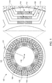
- FIG. 1 illustrates one example of an electric machine assembly 100.
- the electric machine 100 can be a synchronous reluctance and interior permanent magnet machine.
- the electric machine 100 includes a stator 102 having distributed or concentrated conductive windings 104 through which electric current is conducted to cause the electric machine 100 to operate.
- the electric machine 100 also includes a rotor 106 formed from a laminated stack of conductive sheets (e.g., steel sheets), insulated from each other and clamped together.
- the machine assembly 100 can operate as a motor that operates to propel a vehicle.
- the rotor 106 can be rotated by the electric current in the windings 104 of the stator 102, which rotates a shaft joined to the rotor 106.
- This shaft can be coupled with turbine blades, axles, wheels, or the like, to help propel a vehicle such as an airplane, land-based vehicle (e.g., automobile, rail vehicle, mining vehicle, etc.), or marine vessel.
- a vehicle such as an airplane,
- the rotor 106 is formed from a ferromagnetic material that allows magnetic flux to flow through the rotor 106.
- the rotor 106 includes several features that define magnetic flux carrier portions 108 of the rotor 106 and magnetic flux barriers 110 of the rotor 106.
- the flux barriers 110 are portions of the rotor 106 that have been removed, such as air gaps in the rotor 106. Permanent magnets 112 can be placed inside these flux barriers 110. Alternatively, no magnets 112 are in the flux barriers 110.
- the flux carrier portions 108 represent segments of the rotor 106 that remain after the flux barriers 110 are cut from, removed, or otherwise formed in the rotor 106.
- Neighboring flux carrier portions 108 are connected by elongated ferromagnetic posts 114 along radial directions (e.g., directions that radially extend from a center axis or axis of rotation 116 of the rotor 106).
- the ends of the flux carrier portions 108 are connected by elongated bridges 118 along circumferential directions (e.g., directions that circumferentially surround the axis of rotation 116 of the rotor 106).
- the flux carrier portions 108 and/or bridges 118 can be formed when the flux barriers 110 are cut from the sheets forming the rotor 106.
- a varying electric current is conducted through the windings 104 to cause the rotor 106 to rotate relative to the stator 102.
- This current creates magnetic flux in the rotor 106.
- the flux carrier portions 108 guide and carry magnetic flux in the rotor 106 while the barrier portions 110 block or impede flow of the magnetic flux in the rotor 106.
- These portions 108, 110 create a larger reluctance path in the rotor 106 along a first axis 120 (e.g., the quadrature or 'q' axis of the rotor 106) and a smaller reluctance path in the rotor 106 along a different, second axis 122 (e.g., the direct or 'd' axis of the rotor 106).
- the difference in reluctance along the different axes 120, 122 leads to an overall reluctance torque.
- the difference in reluctance can be created by the shape and size of the flux carrier portions 108 and the flux barrier portions 110.
- One problem with the rotor 106 is that a significant amount of magnetic flux can leak of the lower reluctance path along the axis 120 at the posts 114.
- the leaking flux in the posts 114 reduces the power factor of the rotor 106, reduces the torque density of the rotor 106, and can require more current to be conducted through the windings 104 to generate the same amount of torque (as a rotor 106 that does not have as much flux leakage at the posts 114).
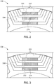
- Figure 2 illustrates one example of a segment of a rotor 206 having flux carrier portions 208 and flux barrier portions 210.
- the rotor 206 can be similar to the rotor 106 shown in Figure 1 , except that the shape and number of the portions 208, 210 may differ from the portions 108, 110 shown in Figure 1 .
- Permanent magnets 232 can be inserted in the barrier portions 210, as described above.
- a post 214 connects neighboring flux carrier portions 208, as described above.
- FIG. 3 illustrates one embodiment of a segment of a rotor 306 having the flux carrier portions 208 and the flux barrier portions 210 shown in Figure 2 .
- the rotor 306 can be similar to the rotors 106, 206, except that the posts 114, 214 in the rotors 106, 206 are removed in the rotor 306. Instead, an airgap 324 is left in the space where the post 214 is located in the rotor 206.
- FIG 4 illustrates examples of airgap torques 426, 428 that are generated by rotation of the rotors 206, 306 with and without the ferromagnetic posts 214, respectively.
- the torques 426, 428 represent the amount of torque generated by rotation of the rotors 206, 306 upon application of the same electric current to the conductive windings 104 in the stator 102 (shown in Figure 1 ).
- the torques 426, 428 are shown alongside a horizontal axis 430 representative of positions of the rotors 206, 306 and alongside a vertical axis 432 representative of torques generated by the rotors 206, 306.
- the torques 428 generated by the rotors 306 that do not include the ferromagnetic posts 114, 214 are significantly greater than the torques 426 generated by the rotors 106, 206 that include the ferromagnetic posts 114, 214.
- removing the ferromagnetic posts 114, 214 can increase the torque generated by rotation of the rotor by an average of 13% across all rotor positions.
- an electric machine assembly 100 includes the stator 102 and the rotor 306 having the airgap 324 in place of the posts 114, 214.
- the airgap 324 can be a space or void that does not include any ferromagnetic material and can be referred to as a non-magnetic space or void.
- the airgap 324 can be bounded by the permanent magnets 323 on both circumferential sides of the airgap 324 (e.g., the opposite sides of the airgap 324 that are along a circumferential direction relative to the rotation axis 116) and can be bounded by the flux carrier portions 208 of the rotor 306 in both radial sides of the airgap 324 (e.g., the opposite sides of the airgap 324 that are along a direction that radially extends away from the rotation axis 116).
- Removal or the absence of the posts 114, 214 can significantly reduce the leakage of magnetic flux from the flux carrier portions 208 of the rotor 306, and therefore can significantly increase the torque or torque density generated by the assembly 100 (and/or reduce the amount of current needed to produce the same torque as an assembly that includes the posts 114, 214).
- the posts 114, 214 provide structural support for the flux carrier portions 208. Removing the posts 114, 214 to leave an empty airgap 324 can, in some embodiments, result in structural damage or failure to the rotor 306 due to the high speeds at which the rotor 306 rotates.
- the airgap 324 is filled or replaced with a non-magnetic post that both reduces leakage of magnetic flux from the flux carrier portions 208 (as the airgap 324 does) and provides structural support to the flux carrier portions 208 to prevent mechanical failure of the portions 208 (which the airgap 324 may not do).
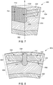
- Figure 5 illustrates a front view of a rotor 506 of the electric machine assembly 100 shown in Figure 1 according to another embodiment.
- Figure 6 illustrates a perspective cut-away view of the segment of the rotor 506 shown in Figure 5 according to one embodiment.
- Figure 7 illustrates a cross-sectional cut-away view of the segment of the rotor 506.
- the rotor 506 includes the flux carrier portions 208 and flux barrier portions 210 described above.
- the magnets 232 can be inserted in the barrier portions 210.
- the rotor 506 is coupled with a shaft 552 that is rotated by the rotor 506 during operation of the assembly 100.
- the rotor 506 optionally can include airgaps (not shown) between the magnets 232 along circumferential directions 534 and located between neighboring flux carrier portions 208 along a radial direction 536.
- the circumferential directions 534 encircle the rotation axis 116 (shown in Figure 1 ) of the rotor 506.
- the radial direction 536 radially extends away from the rotation axis 116.
- These airgaps can be at least partially filled by a non-magnetic post 538.
- the post 538 provides structural support to the flux carrier portions 208 while reducing (or not increasing) the leakage of flux from the flux carrier portions 208.
- the post 538 is a non-magnetic or non-ferromagnetic body formed from one or more materials that are not ferromagnetic materials in one embodiment.
- the post 538 can be formed from one or more of aluminum, non-ferromagnetic stainless steel, titanium, copper beryllium, or any other non-magnetic metal, ceramic, composite material (e.g., such as carbon fiber or alloys), etc.
- the non-magnetic post 538 can be made of an insulating, non-metallic material or a high strength alloy that is electrically nonconductive.
- the post 538 can be formed from thinner sections or plates 740 (shown in Figure 7 ) that are coupled together (e.g., by interlocking, press-fitting, lamination, etc.). These sections or plates 740 can be insulated from each other by including a dielectric layer between neighboring sections or plates 740. Alternatively, the post 538 can be formed as a single and/or homogeneous body that is not formed by coupling multiple parts together.
- the posts 538 are elongated in the radial directions 536 from one flux carrier portion 208 to another flux carrier portion 208, with these carrier portions 208 being on opposite sides of the same flux barrier portion 210.
- the posts 538 also are elongated along the direct axes 120 of the rotors 506.
- Each of the posts 538 is positioned as a bridge between the carrier portions 208 that are on opposite sides of the same barrier portion 210, even though the posts 538 do not carry magnetic flux. For example, the magnetic flux flowing in the carrier portions 208 does not flow through the posts 538 coupling the carrier portions 208 with each other.
- the magnetic flux flows or is carried through the carrier portions 208 and predominantly along the quadrature axes 122 of the assemblies 100 due to the quadrature axes 122 providing lower reluctance paths to the flow of the magnetic flux in the rotors 506 relative to the paths along the direct axes 120 (that extend through the posts 538 along the lengths of the posts 538) of the assemblies 100.
- the illustrated posts 538 have opposite ends 642, 644 (labeled in Figure 6 ) that are joined by an elongated center body 646 (labeled in Figure 6 ).
- the ends 642, 644 can be wider than the center body 646.
- an outer width dimension 648 (labeled in Figure 6 ) of each of the ends 642, 644 can be larger than an outer width dimension 650 (labeled in Figure 6 ) in the middle (along the length) of the center body 646.
- the width dimensions 648, 650 can be measured in the circumferential directions 534 or directions that are parallel to the circumferential directions 534 (e.g., curved directions that do not intersect the circumferential directions).
- the width dimensions 648, 650 can be measured in directions that are perpendicular to the radial direction 536 and that are in the plane defined by the rotor 506 shown in Figure 6 .
- the post 538 shown in Figures 5 through 7 has a dog bone shape, but alternatively can have another shape.
- the post 538 can have a dumbbell shape with a steeper transition between the center body 646 and the ends 642, 644, the post 538 can have a fluted shape with a more gradual transition between the center body 646 and the ends 642, 644, the post 638 can have triangle-shaped ends 642, 644, the post 638 can have dovetail shapes at the ends 642, 644, or the post 638 can have another shape that is able to interlock carrier portions with each other.
- Figure 8 illustrates a front view of a segment of another embodiment of a rotor 806 of the assembly 100.
- the rotor 806 includes the flux carrier portions 208, flux barrier portions 210, magnets 232, and posts 538 described above.
- the rotor 806 also is coupled with the shaft 552 described above.
- the rotor 806 can be a composite rotor that is formed from an assembly 854 of laminated ferromagnetic portions or layers (with the layers being planar and parallel to the plane of Figure 8 ) that are shrink-fitted onto a solid ferromagnetic body 856. This shrink fitting can be performed by creating the laminated portion assembly 854 in larger dimensions that shrink during heating or operation of the rotor 806.
- the rotor is formed by coupling the laminated layers of the assembly 854 with the solid body 856 using the posts 538.
- the laminated assembly 854 is coupled with the solid body 856 at an interface 858.
- the posts 538 can then be axially slid or otherwise inserted into the airgaps 524.
- the non-magnetic post 538 can be a part/extension of the shaft 552 (made of same material as 538) wherein the non-magnetic assembly can be axially inserted into the preformed cuts on laminated ferromagnetic portion 854 and solid ferromagnetic portion 856.
- the posts 538 can be additively manufactured. For example, three-dimensional printing can be used to print the posts in the airgaps of the rotor so that the posts are formed within the rotor and are not formed before placing the posts in the airgaps of the rotor.
- the rotor 506, 806 shown in Figures 5 through 8 can include one or more stress relief features. These relief features can include small cut outs or extensions of the airgap 524 into which the post 538 is inserted.
- each stress relief features can be an arch-shaped cutout or removal of the rotor 506, 806 that axially extends through the layers of the rotor 506, 806.
- the relief features can be located radially inward and outward of the post 538.
- one relief feature can be located between the rotation axis 116 of the rotor 506, 806 and the post 538 along the radial direction 536, while another relief feature can be located between the post 538 and the stator 102 along the radial direction 536.
- Adding the relief features to the rotor 506, 806 can significantly reduce the mechanical stress imparted on or experienced by the rotor 506, 806 at interfaces between the rotor 506, 806 and the post 538 on both sides of the radial direction 536.
- adding the relief features to the rotor 506, 806 can reduce the maximum principal stress exerted on the rotor 506, 806 at interfaces between the rotor 506, 806 and the post 538 on both sides of the radial direction 536 by at least one order of magnitude.
- addition of the relief features reduces the maximum principal stress by at least 14%.
- FIG 10 illustrates another embodiment of a rotor 1006 of the electric machine assembly 100 shown in Figure 1 according to another embodiment.
- the rotor 1006 includes the flux carrier portions 208 and the flux barrier portions 210 described above.
- One difference between the rotor 1006 and other rotors shown and/or described herein is the presence of one or more posts 214 within the flux barrier portions 210 and multiple, separate magnets 232 in one or more of the flux barrier portions 210.
- posts 214 can radially extend through a flux barrier portion 210 to subdivide the flux barrier portion 210 into multiple, separate chambers.
- Separate magnets 232 can be inserted into two or more of these chambers defined by the posts 214, also as shown in Figure 10 .
- a flux barrier portion 210 can be divided into a different number of separate chambers by a different number of posts 214 and/or a different number of magnets 232 can be inserted into the same flux barrier portion 210.
- Figure 9 illustrates a flowchart of one embodiment of a method 900 for manufacturing a rotor of an electric machine assembly.
- the method 900 can be used to create one or more of the rotors 506, 806 described herein.
- several magnetically conductive sheets are obtained. These sheets can be conductive such that magnetic flux is able to flow through the sheets.
- the sheets can be cut into the shape of the rotor (e.g., into circles).
- elongated magnetic flux carrier portions are formed into the magnetically conductive sheets. These carrier portions 208 can be formed by cutting elongated magnetic flux barriers 210 into the conductive sheets. The barriers 210 can be cut into the conductive sheets such that the magnetic flux barriers 210 are separated from each other in radial directions 536 of the conductive sheets. The conductive sheets can be laminated together prior to or after forming the carrier portions.
- non-magnetic posts are inserted into the magnetic flux barriers.
- the posts 538 can be inserted into airgaps 524 formed by the flux barriers 210.
- the airgaps 524 can be oriented such that each of the non-magnetic posts 538 is elongated in a different radial direction 536 outward from the rotation axis 116 of the rotor 506, 806.
- the posts 538 are inserted into the airgaps 524 such that the posts 538 extend from one magnetic flux carrier portion 208 to another magnetic flux carrier portion 208 on opposite sides the magnetic flux barrier 210.
- the rotor is formed using the conductive sheets having the magnetic flux carrier portions, the non-magnetic posts, and the magnetic flux barriers.
- the rotor 506, 806 can be inserted into the stator 102.
- the rotor 506, 806 can be formed by combining a laminate assembly 854 of the conductive sheets with a solid body 856 of ferromagnetic material at an interface 858 that extends through the airgaps 524 and the posts 538.
- an electric machine assembly in one embodiment, includes a rotor formed from one or more conductive sheets having elongated magnetic flux barriers separated from each other in radial directions that radially extend away from an axis of rotation of the rotor.
- the magnetic flux barriers are separated from each other by magnetic flux carrier portions of the one or more conductive sheets.
- the assembly also includes a non-magnetic post coupled with the magnetic flux carrier portions of the one or more conductive sheets on opposite sides of at least one of the magnetic flux barriers.
- the non-magnetic post is elongated in the radial directions from a first magnetic flux carrier portion to a second magnetic flux carrier portion of the magnetic flux carrier portions on the opposite sides of the at least one magnetic flux barrier.
- the non-magnetic post reduces magnetic flux leakage from the one or more conductive sheets such that a torque generated by operation of the rotor is increased relative to another rotor that does not include the non-magnetic post at the same rotor speed and stator excitation.
- the non-magnetic post is elongated along a direct axis of the rotor having a greater reluctance than a quadrature axis of the rotor.
- the non-magnetic post is formed from one or more of aluminum, non-ferromagnetic steel, titanium, copper beryllium, another non-ferromagnetic metal material, a ceramic material, a composite material (such as but not limited to carbon fiber), an alloy, or any other non-magnetic material.
- the non-magnetic post is formed from an electrically insulating material.
- the non-magnetic post includes opposite ends joined by an elongated center body.
- the opposite ends can have larger width dimensions in directions that are transverse to the radial directions than a width dimension of the center body in the directions that are transverse to the radial direction.
- the non-magnetic post has a dog bone shape, a dumbbell shape, an hourglass shape, a dovetail shape, or any other shape capable of having interlocking mechanisms between parts of the rotor.
- the assembly also includes one or more magnets disposed in the magnetic flux barriers.
- a rotor of an electric machine assembly includes plural magnetically conductive sheets laminated with each other.
- the conductive sheets have elongated magnetic flux barriers separated from each other in radial directions that radially extend away from an axis of rotation of the rotor.
- the magnetic flux barriers are separated from each other by magnetic flux carrier portions of the one or more conductive sheets.
- the rotor also includes multiple non-magnetic posts which are laminated, insulated and coupled with the magnetic flux carrier portions of the one or more conductive sheets on opposite sides of at least one of the magnetic flux barriers.
- the non-magnetic posts are elongated in the radial directions from a first magnetic flux carrier portion to a second magnetic flux carrier portion of the magnetic flux carrier portions on the opposite sides of each of the magnetic flux barriers.
- the non-magnetic posts reduce magnetic flux leakage from the one or more conductive sheets such that a torque generated by operation of the electric motor assembly is increased relative to another electric motor assembly that does not include the non-magnetic posts at the same rotor speed and stator excitation.
- At least one of the non-magnetic posts is elongated along a direct axis of the conductive sheets having a greater reluctance than a quadrature axis of the conductive sheets.
- the non-magnetic posts are formed from one or more of aluminum, non-ferromagnetic steel, titanium, copper-beryllium, another non-ferromagnetic metal, a ceramic, a composite material (such as but not limited to carbon fiber).
- the non-magnetic posts are formed from an electrically insulative material.
- each of the non-magnetic posts includes opposite ends joined by an elongated center body.
- the opposite ends can have larger width dimensions in directions that are transverse to the radial directions than a width dimension of the center body in the directions that are transverse to the radial direction.
- each of the non-magnetic posts has a dog bone shape, dumbbell shape, hour-glass shape, dovetail shape, or another suitable shape capable of having interlocking mechanisms between the parts of the rotor.
- the rotor also includes one or more magnets disposed in the magnetic flux barriers.
- a method includes obtaining magnetically conductive sheets and forming elongated magnetic flux carrier portions of the conductive sheets by cutting elongated magnetic flux barriers into the conductive sheets.
- the magnetic flux barriers are cut into the conductive sheets such that the magnetic flux barriers are separated from each other in radial directions of the conductive sheets.
- the method also includes inserting or forming non-magnetic posts into the magnetic flux barriers such that each of the non-magnetic post is elongated in a different radial direction of the radial directions from a first magnetic flux carrier portion to a second magnetic flux carrier portion of the magnetic flux carrier portions on opposite sides of at least one magnetic flux barrier, and forming at least part of a rotor for an electric machine assembly using the conductive sheets having the magnetic flux carrier portions, the non-magnetic posts, and the magnetic flux barriers.
- inserting the non-magnetic posts reduces magnetic flux leakage from the rotor such that a torque generated by operation of the rotor is increased relative to another rotor that does not include the non-magnetic post at the same rotor speed and stator excitation.
- the non-magnetic posts are inserted into the magnetic flux barriers such that at least one of the non-magnetic posts is elongated along a direct axis of the rotor having a greater reluctance than a quadrature axis of the rotor.
- forming the magnetic flux carrier portions includes cutting elongated openings that are oriented along the radial directions of the conductive sheets, the elongated openings having wider opposite end holes joined by a thinner elongated slot.
- inserting the non-magnetic posts into the magnetic flux barriers includes inserting wider opposite ends of the non-magnetic posts into the wider opposite end holes of the elongated openings and elongated center bodies of the non-magnetic posts into the elongated slot.
- the method also includes inserting magnets into the magnetic flux barriers.
- forming at least part of the rotor includes fixing a preformed laminated section of the rotor to a solid body of the rotor using one or more of shrink-fitting or the posts.
Landscapes
- Engineering & Computer Science (AREA)
- Power Engineering (AREA)
- Manufacturing & Machinery (AREA)
- Permanent Field Magnets Of Synchronous Machinery (AREA)
- Iron Core Of Rotating Electric Machines (AREA)
Abstract
Description
- The subject matter described herein relates to electric machines, such as electric motors.
- Electric machines such as synchronous reluctance and interior permanent magnet (IPM) machines rely on the flow of magnetic flux in rotors of the machines to generate torque. The rotors include mechanical features (e.g., shapes) which act as magnetic flux guiding channels and other features that operate as flux barriers. These guiding channels provide a smaller reluctance path along one axis of the machine (e.g., the direct or d-axis) and the flux barriers provide a greater reluctance path along another axis of the machine (e.g., the quadrature or q-axis). The difference in reluctance along these different paths and axes provides an overall reluctance torque.
- The difference in reluctance is created by the shape and size of the flux guiding channels and flux barriers in the rotor. Due to the speed at which the rotor spins during operation, the flux guiding channels may be subject to large forces. Posts can extend between the channels and bridges can connect the ends of the channels to provide structural support to the flux guiding channels. But, these posts and bridges provide locations for increased flux leakage in the machine. This flux leakage decreases the power factor and torque density of the machines, and can require increased voltages to be supplied to power the machines.
- In one embodiment, an electric machine assembly includes a rotor formed from one or more conductive sheets having elongated magnetic flux barriers separated from each other in radial directions that radially extend away from an axis of rotation of the rotor. The magnetic flux barriers are separated from each other by magnetic flux carrier portions of the one or more conductive sheets. The assembly also includes a non-magnetic post coupled with the magnetic flux carrier portions of the one or more conductive sheets on opposite sides of at least one of the magnetic flux barriers. The non-magnetic post is elongated in the radial directions from a first magnetic flux carrier portion to a second magnetic flux carrier portion of the magnetic flux carrier portions on the opposite sides of the at least one magnetic flux barrier.
- In one embodiment, a rotor of an electric machine assembly includes plural conductive sheets laminated with each other. The conductive sheets have elongated magnetic flux barriers separated from each other in radial directions that radially extend away from an axis of rotation of the rotor. The magnetic flux barriers are separated from each other by magnetic flux carrier portions of the one or more conductive sheets. The rotor also includes non-magnetic posts coupled with the magnetic flux carrier portions of the one or more conductive sheets on opposite sides of at least one of the magnetic flux barriers. The non-magnetic posts are elongated in the radial directions from a first magnetic flux carrier portion to a second magnetic flux carrier portion of the magnetic flux carrier portions on the opposite sides of each of the magnetic flux barriers.
- The present inventive subject matter will be better understood from reading the following description of non-limiting embodiments, with reference to the attached drawings, wherein below:
-
Figure 1 illustrates one example of an electric machine assembly; -
Figure 2 illustrates one example of a segment of a rotor of the machine assembly shown inFigure 1 having flux carrier portions and flux barrier portions; -
Figure 3 illustrates one embodiment of a segment of a rotor of the machine assembly shown inFigure 1 having the flux carrier portions and the flux barrier portions shown inFigure 2 ; -
Figure 4 illustrates examples of airgap torques that are generated by rotation of the rotors shown inFigures 2 and 3 with and without ferromagnetic posts shown inFigure 2 ; -
Figure 5 illustrates a front view of a rotor of the electric machine assembly shown inFigure 1 according to another embodiment; -
Figure 6 illustrates a perspective cut-away view of the segment of the rotor shown inFigure 5 according to one embodiment; -
Figure 7 illustrates a cross-sectional cut-away view of the segment of the rotor shown inFigures 5 and 6 ; -
Figure 8 illustrates a front view of a segment of another embodiment of a rotor of the machine assembly shown inFigure 1 ; -
Figure 9 illustrates a flowchart of one embodiment of a method for manufacturing a rotor of an electric machine assembly; and -
Figure 10 illustrates another embodiment of a rotor of the electric machine assembly shown inFigure 1 according to another embodiment. - One or more embodiments of the inventive subject matter described herein relate to electric machine assemblies that provide for improved torque density due at least in part to changes in the features in the machines that provide for magnetic flux carrier portions and/or magnetic flux barrier portions. The machines can be synchronous reluctance and interior permanent magnet machines. A stator of the machine can be a stator having distributed or concentrated windings. A rotor of the machine includes a laminated stack of electrical sheets (e.g., steel sheets) that are insulated from each other and clamped together. The rotor includes features that operate as magnetic flux guiding channels having a lower reluctance along the quadrature or q-axis of the machine, and a higher reluctance along the direct or d-axis of the machine.
- The difference in reluctance along the different axes leads to an overall reluctance torque of the machine. The difference in reluctance is created by the shape and size of the flux carrier portions and the flux barrier portions of the rotor. In one embodiment of the inventive subject matter, the ferromagnetic posts that are present in some known electric machines are replaced with non-magnetic posts, or posts that are not formed from a ferromagnetic material and therefore do not allow magnetic flux to flow through the non-magnetic posts. Removing the magnetic posts from the rotor can reduce the flux leakage that occurs in the posts of known machines. This can improve the power factor of the machine by increasing the torque density of the machine and/or reducing the voltage needed to generate the same amount of torque (as a machine with ferromagnetic posts).
- In one embodiment, the non-ferromagnetic posts described herein are formed from one or more dielectric or insulating materials, and are not formed from a dual phase magnetic material. Dual phase magnetic materials can be made non-magnetic at selected locations, but these materials can have relatively low mechanical strength (e.g., no greater than 80 ksi). This lower strength may result in damage or destruction of the posts in some machines. Conversely, using the non-ferromagnetic posts described herein can reduce flux leakage while providing a greater mechanical strength (e.g., greater than 80 ksi and up to 200 ksi or more).
-
Figure 1 illustrates one example of anelectric machine assembly 100. Theelectric machine 100 can be a synchronous reluctance and interior permanent magnet machine. Theelectric machine 100 includes astator 102 having distributed or concentratedconductive windings 104 through which electric current is conducted to cause theelectric machine 100 to operate. Theelectric machine 100 also includes arotor 106 formed from a laminated stack of conductive sheets (e.g., steel sheets), insulated from each other and clamped together. Themachine assembly 100 can operate as a motor that operates to propel a vehicle. For example, therotor 106 can be rotated by the electric current in thewindings 104 of thestator 102, which rotates a shaft joined to therotor 106. This shaft can be coupled with turbine blades, axles, wheels, or the like, to help propel a vehicle such as an airplane, land-based vehicle (e.g., automobile, rail vehicle, mining vehicle, etc.), or marine vessel. - The
rotor 106 is formed from a ferromagnetic material that allows magnetic flux to flow through therotor 106. Therotor 106 includes several features that define magneticflux carrier portions 108 of therotor 106 andmagnetic flux barriers 110 of therotor 106. Theflux barriers 110 are portions of therotor 106 that have been removed, such as air gaps in therotor 106.Permanent magnets 112 can be placed inside theseflux barriers 110. Alternatively, nomagnets 112 are in theflux barriers 110. Theflux carrier portions 108 represent segments of therotor 106 that remain after theflux barriers 110 are cut from, removed, or otherwise formed in therotor 106. - Neighboring
flux carrier portions 108 are connected by elongatedferromagnetic posts 114 along radial directions (e.g., directions that radially extend from a center axis or axis ofrotation 116 of the rotor 106). The ends of theflux carrier portions 108 are connected byelongated bridges 118 along circumferential directions (e.g., directions that circumferentially surround the axis ofrotation 116 of the rotor 106). Theflux carrier portions 108 and/orbridges 118 can be formed when theflux barriers 110 are cut from the sheets forming therotor 106. - In operation, a varying electric current is conducted through the
windings 104 to cause therotor 106 to rotate relative to thestator 102. This current creates magnetic flux in therotor 106. Theflux carrier portions 108 guide and carry magnetic flux in therotor 106 while thebarrier portions 110 block or impede flow of the magnetic flux in therotor 106. Theseportions rotor 106 along a first axis 120 (e.g., the quadrature or 'q' axis of the rotor 106) and a smaller reluctance path in therotor 106 along a different, second axis 122 (e.g., the direct or 'd' axis of the rotor 106). The difference in reluctance along thedifferent axes flux carrier portions 108 and theflux barrier portions 110. - One problem with the
rotor 106 is that a significant amount of magnetic flux can leak of the lower reluctance path along theaxis 120 at theposts 114. The leaking flux in theposts 114 reduces the power factor of therotor 106, reduces the torque density of therotor 106, and can require more current to be conducted through thewindings 104 to generate the same amount of torque (as arotor 106 that does not have as much flux leakage at the posts 114). -
Figure 2 illustrates one example of a segment of arotor 206 havingflux carrier portions 208 andflux barrier portions 210. Therotor 206 can be similar to therotor 106 shown inFigure 1 , except that the shape and number of theportions portions Figure 1 .Permanent magnets 232 can be inserted in thebarrier portions 210, as described above. Apost 214 connects neighboringflux carrier portions 208, as described above. - One option to reduce the flux leakage at the
posts rotors posts Figure 3 illustrates one embodiment of a segment of arotor 306 having theflux carrier portions 208 and theflux barrier portions 210 shown inFigure 2 . Therotor 306 can be similar to therotors posts rotors rotor 306. Instead, anairgap 324 is left in the space where thepost 214 is located in therotor 206. - Removing the
ferromagnetic post rotors axes 120 in therotors Figure 4 illustrates examples of airgap torques 426, 428 that are generated by rotation of therotors ferromagnetic posts 214, respectively. Thetorques rotors conductive windings 104 in the stator 102 (shown inFigure 1 ). Thetorques horizontal axis 430 representative of positions of therotors vertical axis 432 representative of torques generated by therotors torques 428 generated by therotors 306 that do not include theferromagnetic posts torques 426 generated by therotors ferromagnetic posts ferromagnetic posts - In one embodiment, an
electric machine assembly 100 includes thestator 102 and therotor 306 having theairgap 324 in place of theposts airgap 324 can be a space or void that does not include any ferromagnetic material and can be referred to as a non-magnetic space or void. Theairgap 324 can be bounded by the permanent magnets 323 on both circumferential sides of the airgap 324 (e.g., the opposite sides of theairgap 324 that are along a circumferential direction relative to the rotation axis 116) and can be bounded by theflux carrier portions 208 of therotor 306 in both radial sides of the airgap 324 (e.g., the opposite sides of theairgap 324 that are along a direction that radially extends away from the rotation axis 116). Removal or the absence of theposts flux carrier portions 208 of therotor 306, and therefore can significantly increase the torque or torque density generated by the assembly 100 (and/or reduce the amount of current needed to produce the same torque as an assembly that includes theposts 114, 214). - But, removing the
posts assembly 100. Theposts flux carrier portions 208. Removing theposts empty airgap 324 can, in some embodiments, result in structural damage or failure to therotor 306 due to the high speeds at which therotor 306 rotates. In another embodiment, theairgap 324 is filled or replaced with a non-magnetic post that both reduces leakage of magnetic flux from the flux carrier portions 208 (as theairgap 324 does) and provides structural support to theflux carrier portions 208 to prevent mechanical failure of the portions 208 (which theairgap 324 may not do). -
Figure 5 illustrates a front view of arotor 506 of theelectric machine assembly 100 shown inFigure 1 according to another embodiment.Figure 6 illustrates a perspective cut-away view of the segment of therotor 506 shown inFigure 5 according to one embodiment.Figure 7 illustrates a cross-sectional cut-away view of the segment of therotor 506. Therotor 506 includes theflux carrier portions 208 andflux barrier portions 210 described above. Themagnets 232 can be inserted in thebarrier portions 210. Therotor 506 is coupled with ashaft 552 that is rotated by therotor 506 during operation of theassembly 100. - The
rotor 506 optionally can include airgaps (not shown) between themagnets 232 alongcircumferential directions 534 and located between neighboringflux carrier portions 208 along aradial direction 536. Thecircumferential directions 534 encircle the rotation axis 116 (shown inFigure 1 ) of therotor 506. Theradial direction 536 radially extends away from therotation axis 116. These airgaps can be at least partially filled by anon-magnetic post 538. - The
post 538 provides structural support to theflux carrier portions 208 while reducing (or not increasing) the leakage of flux from theflux carrier portions 208. Thepost 538 is a non-magnetic or non-ferromagnetic body formed from one or more materials that are not ferromagnetic materials in one embodiment. For example, thepost 538 can be formed from one or more of aluminum, non-ferromagnetic stainless steel, titanium, copper beryllium, or any other non-magnetic metal, ceramic, composite material (e.g., such as carbon fiber or alloys), etc. Optionally, thenon-magnetic post 538 can be made of an insulating, non-metallic material or a high strength alloy that is electrically nonconductive. Thepost 538 can be formed from thinner sections or plates 740 (shown inFigure 7 ) that are coupled together (e.g., by interlocking, press-fitting, lamination, etc.). These sections orplates 740 can be insulated from each other by including a dielectric layer between neighboring sections orplates 740. Alternatively, thepost 538 can be formed as a single and/or homogeneous body that is not formed by coupling multiple parts together. - The
posts 538 are elongated in theradial directions 536 from oneflux carrier portion 208 to anotherflux carrier portion 208, with thesecarrier portions 208 being on opposite sides of the sameflux barrier portion 210. Theposts 538 also are elongated along thedirect axes 120 of therotors 506. Each of theposts 538 is positioned as a bridge between thecarrier portions 208 that are on opposite sides of thesame barrier portion 210, even though theposts 538 do not carry magnetic flux. For example, the magnetic flux flowing in thecarrier portions 208 does not flow through theposts 538 coupling thecarrier portions 208 with each other. Instead, the magnetic flux flows or is carried through thecarrier portions 208 and predominantly along the quadrature axes 122 of theassemblies 100 due to the quadrature axes 122 providing lower reluctance paths to the flow of the magnetic flux in therotors 506 relative to the paths along the direct axes 120 (that extend through theposts 538 along the lengths of the posts 538) of theassemblies 100. - The illustrated
posts 538 have opposite ends 642, 644 (labeled inFigure 6 ) that are joined by an elongated center body 646 (labeled inFigure 6 ). The ends 642, 644 can be wider than thecenter body 646. For example, an outer width dimension 648 (labeled inFigure 6 ) of each of theends Figure 6 ) in the middle (along the length) of thecenter body 646. Thewidth dimensions circumferential directions 534 or directions that are parallel to the circumferential directions 534 (e.g., curved directions that do not intersect the circumferential directions). Alternatively, thewidth dimensions radial direction 536 and that are in the plane defined by therotor 506 shown inFigure 6 . - The
post 538 shown inFigures 5 through 7 has a dog bone shape, but alternatively can have another shape. For example, thepost 538 can have a dumbbell shape with a steeper transition between thecenter body 646 and theends post 538 can have a fluted shape with a more gradual transition between thecenter body 646 and theends ends -
Figure 8 illustrates a front view of a segment of another embodiment of arotor 806 of theassembly 100. Therotor 806 includes theflux carrier portions 208,flux barrier portions 210,magnets 232, andposts 538 described above. Therotor 806 also is coupled with theshaft 552 described above. Therotor 806 can be a composite rotor that is formed from anassembly 854 of laminated ferromagnetic portions or layers (with the layers being planar and parallel to the plane ofFigure 8 ) that are shrink-fitted onto a solidferromagnetic body 856. This shrink fitting can be performed by creating thelaminated portion assembly 854 in larger dimensions that shrink during heating or operation of therotor 806. This shrinking can reduce the dimensions of theassembly 854 to dimensions that couple and secure theassembly 854 to thebody 856. Alternatively, a dove tail or other interlocking mechanism can be used to couple thelaminated assembly 854 with thesolid body 856. In one embodiment, the rotor is formed by coupling the laminated layers of theassembly 854 with thesolid body 856 using theposts 538. Thelaminated assembly 854 is coupled with thesolid body 856 at aninterface 858. Theposts 538 can then be axially slid or otherwise inserted into theairgaps 524. This manufacturing technique can enable the separate portions of thelaminated assembly 854, which experience greater electromagnetic losses (e.g., flux leakage), to be laminated together, while other portions that do not experience as much electromagnetic losses to be solid bodies (and thereby easier to forge or machine). In another embodiment, thenon-magnetic post 538 can be a part/extension of the shaft 552 (made of same material as 538) wherein the non-magnetic assembly can be axially inserted into the preformed cuts on laminatedferromagnetic portion 854 and solidferromagnetic portion 856. Alternatively, theposts 538 can be additively manufactured. For example, three-dimensional printing can be used to print the posts in the airgaps of the rotor so that the posts are formed within the rotor and are not formed before placing the posts in the airgaps of the rotor. - In one embodiment, the
rotor Figures 5 through 8 can include one or more stress relief features. These relief features can include small cut outs or extensions of theairgap 524 into which thepost 538 is inserted. For example, each stress relief features can be an arch-shaped cutout or removal of therotor rotor post 538. For example, one relief feature can be located between therotation axis 116 of therotor post 538 along theradial direction 536, while another relief feature can be located between thepost 538 and thestator 102 along theradial direction 536. Adding the relief features to therotor rotor rotor post 538 on both sides of theradial direction 536. For example, adding the relief features to therotor rotor rotor post 538 on both sides of theradial direction 536 by at least one order of magnitude. In one embodiment, addition of the relief features reduces the maximum principal stress by at least 14%. -
Figure 10 illustrates another embodiment of arotor 1006 of theelectric machine assembly 100 shown inFigure 1 according to another embodiment. Therotor 1006 includes theflux carrier portions 208 and theflux barrier portions 210 described above. One difference between therotor 1006 and other rotors shown and/or described herein is the presence of one ormore posts 214 within theflux barrier portions 210 and multiple,separate magnets 232 in one or more of theflux barrier portions 210. As shown inFigure 10 ,posts 214 can radially extend through aflux barrier portion 210 to subdivide theflux barrier portion 210 into multiple, separate chambers.Separate magnets 232 can be inserted into two or more of these chambers defined by theposts 214, also as shown inFigure 10 . Optionally, aflux barrier portion 210 can be divided into a different number of separate chambers by a different number ofposts 214 and/or a different number ofmagnets 232 can be inserted into the sameflux barrier portion 210. -
Figure 9 illustrates a flowchart of one embodiment of amethod 900 for manufacturing a rotor of an electric machine assembly. Themethod 900 can be used to create one or more of therotors - At 904, elongated magnetic flux carrier portions are formed into the magnetically conductive sheets. These
carrier portions 208 can be formed by cutting elongatedmagnetic flux barriers 210 into the conductive sheets. Thebarriers 210 can be cut into the conductive sheets such that themagnetic flux barriers 210 are separated from each other inradial directions 536 of the conductive sheets. The conductive sheets can be laminated together prior to or after forming the carrier portions. - At 906, non-magnetic posts are inserted into the magnetic flux barriers. For example, the
posts 538 can be inserted intoairgaps 524 formed by theflux barriers 210. Theairgaps 524 can be oriented such that each of thenon-magnetic posts 538 is elongated in a differentradial direction 536 outward from therotation axis 116 of therotor posts 538 are inserted into theairgaps 524 such that theposts 538 extend from one magneticflux carrier portion 208 to another magneticflux carrier portion 208 on opposite sides themagnetic flux barrier 210. - At 908, the rotor is formed using the conductive sheets having the magnetic flux carrier portions, the non-magnetic posts, and the magnetic flux barriers. For example, the
rotor stator 102. Optionally, therotor laminate assembly 854 of the conductive sheets with asolid body 856 of ferromagnetic material at aninterface 858 that extends through theairgaps 524 and theposts 538. - In one embodiment, an electric machine assembly includes a rotor formed from one or more conductive sheets having elongated magnetic flux barriers separated from each other in radial directions that radially extend away from an axis of rotation of the rotor. The magnetic flux barriers are separated from each other by magnetic flux carrier portions of the one or more conductive sheets. The assembly also includes a non-magnetic post coupled with the magnetic flux carrier portions of the one or more conductive sheets on opposite sides of at least one of the magnetic flux barriers. The non-magnetic post is elongated in the radial directions from a first magnetic flux carrier portion to a second magnetic flux carrier portion of the magnetic flux carrier portions on the opposite sides of the at least one magnetic flux barrier.
- Optionally, the non-magnetic post reduces magnetic flux leakage from the one or more conductive sheets such that a torque generated by operation of the rotor is increased relative to another rotor that does not include the non-magnetic post at the same rotor speed and stator excitation.
- Optionally, the non-magnetic post is elongated along a direct axis of the rotor having a greater reluctance than a quadrature axis of the rotor.
- Optionally, the non-magnetic post is formed from one or more of aluminum, non-ferromagnetic steel, titanium, copper beryllium, another non-ferromagnetic metal material, a ceramic material, a composite material (such as but not limited to carbon fiber), an alloy, or any other non-magnetic material.
- Optionally, the non-magnetic post is formed from an electrically insulating material.
- Optionally, the non-magnetic post includes opposite ends joined by an elongated center body. The opposite ends can have larger width dimensions in directions that are transverse to the radial directions than a width dimension of the center body in the directions that are transverse to the radial direction.
- Optionally, the non-magnetic post has a dog bone shape, a dumbbell shape, an hourglass shape, a dovetail shape, or any other shape capable of having interlocking mechanisms between parts of the rotor.
- Optionally, the assembly also includes one or more magnets disposed in the magnetic flux barriers.
- In one embodiment, a rotor of an electric machine assembly includes plural magnetically conductive sheets laminated with each other. The conductive sheets have elongated magnetic flux barriers separated from each other in radial directions that radially extend away from an axis of rotation of the rotor. The magnetic flux barriers are separated from each other by magnetic flux carrier portions of the one or more conductive sheets. The rotor also includes multiple non-magnetic posts which are laminated, insulated and coupled with the magnetic flux carrier portions of the one or more conductive sheets on opposite sides of at least one of the magnetic flux barriers. The non-magnetic posts are elongated in the radial directions from a first magnetic flux carrier portion to a second magnetic flux carrier portion of the magnetic flux carrier portions on the opposite sides of each of the magnetic flux barriers.
- Optionally, the non-magnetic posts reduce magnetic flux leakage from the one or more conductive sheets such that a torque generated by operation of the electric motor assembly is increased relative to another electric motor assembly that does not include the non-magnetic posts at the same rotor speed and stator excitation.
- Optionally, at least one of the non-magnetic posts is elongated along a direct axis of the conductive sheets having a greater reluctance than a quadrature axis of the conductive sheets.
- Optionally, the non-magnetic posts are formed from one or more of aluminum, non-ferromagnetic steel, titanium, copper-beryllium, another non-ferromagnetic metal, a ceramic, a composite material (such as but not limited to carbon fiber).
- Optionally, the non-magnetic posts are formed from an electrically insulative material.
- Optionally, each of the non-magnetic posts includes opposite ends joined by an elongated center body. The opposite ends can have larger width dimensions in directions that are transverse to the radial directions than a width dimension of the center body in the directions that are transverse to the radial direction.
- Optionally, each of the non-magnetic posts has a dog bone shape, dumbbell shape, hour-glass shape, dovetail shape, or another suitable shape capable of having interlocking mechanisms between the parts of the rotor.
- Optionally, the rotor also includes one or more magnets disposed in the magnetic flux barriers.
- In one embodiment, a method includes obtaining magnetically conductive sheets and forming elongated magnetic flux carrier portions of the conductive sheets by cutting elongated magnetic flux barriers into the conductive sheets. The magnetic flux barriers are cut into the conductive sheets such that the magnetic flux barriers are separated from each other in radial directions of the conductive sheets. The method also includes inserting or forming non-magnetic posts into the magnetic flux barriers such that each of the non-magnetic post is elongated in a different radial direction of the radial directions from a first magnetic flux carrier portion to a second magnetic flux carrier portion of the magnetic flux carrier portions on opposite sides of at least one magnetic flux barrier, and forming at least part of a rotor for an electric machine assembly using the conductive sheets having the magnetic flux carrier portions, the non-magnetic posts, and the magnetic flux barriers.
- Optionally, inserting the non-magnetic posts reduces magnetic flux leakage from the rotor such that a torque generated by operation of the rotor is increased relative to another rotor that does not include the non-magnetic post at the same rotor speed and stator excitation.
- Optionally, the non-magnetic posts are inserted into the magnetic flux barriers such that at least one of the non-magnetic posts is elongated along a direct axis of the rotor having a greater reluctance than a quadrature axis of the rotor.
- Optionally, forming the magnetic flux carrier portions includes cutting elongated openings that are oriented along the radial directions of the conductive sheets, the elongated openings having wider opposite end holes joined by a thinner elongated slot.
- Optionally, inserting the non-magnetic posts into the magnetic flux barriers includes inserting wider opposite ends of the non-magnetic posts into the wider opposite end holes of the elongated openings and elongated center bodies of the non-magnetic posts into the elongated slot.
- Optionally, the method also includes inserting magnets into the magnetic flux barriers.
- Optionally, forming at least part of the rotor includes fixing a preformed laminated section of the rotor to a solid body of the rotor using one or more of shrink-fitting or the posts.
- It is to be understood that the above description is intended to be illustrative, and not restrictive. For example, the above-described embodiments (and/or aspects thereof) may be used in combination with each other. In addition, many modifications may be made to adapt a particular situation or material to the teachings of the inventive subject matter without departing from its scope. While the dimensions and types of materials described herein are intended to define the parameters of the inventive subject matter, they are by no means limiting and are exemplary embodiments. Many other embodiments will be apparent to one of ordinary skill in the art upon reviewing the above description. The scope of the inventive subject matter should, therefore, be determined with reference to the appended claims, along with the full scope of equivalents to which such claims are entitled. In the appended claims, the terms "including" and "in which" are used as the plain-English equivalents of the respective terms "comprising" and "wherein." Moreover, in the following claims, the terms "first," "second," and "third," etc. are used merely as labels, and are not intended to impose numerical requirements on their objects. Further, the limitations of the following claims are not written in means-plus-function format and are not intended to be interpreted based on 35 U.S.C. § 112(f), unless and until such claim limitations expressly use the phrase "means for" followed by a statement of function void of further structure.
- This written description uses examples to disclose several embodiments of the inventive subject matter, and also to enable one of ordinary skill in the art to practice the embodiments of inventive subject matter, including making and using any devices or systems and performing any incorporated methods. The patentable scope of the inventive subject matter is defined by the claims, and may include other examples that occur to one of ordinary skill in the art. Such other examples are intended to be within the scope of the claims if they have structural elements that do not differ from the literal language of the claims, or if they include equivalent structural elements with insubstantial differences from the literal languages of the claims.
- The foregoing description of certain embodiments of the present inventive subject matter will be better understood when read in conjunction with the appended drawings. The various embodiments are not limited to the arrangements and instrumentality shown in the drawings.
- As used herein, an element or step recited in the singular and proceeded with the word "a" or "an" should be understood as not excluding plural of said elements or steps, unless such exclusion is explicitly stated. Furthermore, references to "one embodiment" of the present invention are not intended to be interpreted as excluding the existence of additional embodiments that also incorporate the recited features. Moreover, unless explicitly stated to the contrary, embodiments "comprising," "comprises," "including," "includes," "having," or "has" an element or a plurality of elements having a particular property may include additional such elements not having that property.
- Further aspects of the invention are provided by the subject matter of the following clauses:
- 1. An electric machine assembly including a rotor formed from one or more magnetically conductive sheets having elongated magnetic flux barriers separated from each other in radial directions that radially extend away from an axis of rotation of the rotor, the magnetic flux barriers separated from each other by magnetic flux carrier portions of the one or more conductive sheets, and a non-magnetic post coupled with the magnetic flux carrier portions of the one or more magnetically conductive sheets on opposite sides of at least one of the magnetic flux barriers, the non-magnetic post elongated in the radial directions from a first magnetic flux carrier portion to a second magnetic flux carrier portion of the magnetic flux carrier portions on the opposite sides of the at least one magnetic flux barrier.
- 2. The electric machine assembly of any preceding clause, wherein the non-magnetic post reduces magnetic flux leakage from the one or more magnetically conductive sheets such that a torque generated by operation of the rotor is increased relative to another rotor that does not include the non-magnetic post at the same rotor speed and stator excitation.
- 3. The electric machine assembly of any preceding clause, wherein the non-magnetic post is elongated along a direct axis of the rotor having a greater reluctance than a quadrature axis of the rotor.
- 4. The electric machine assembly of any preceding clause, wherein the non-magnetic post is formed from one or more of aluminum, non-ferromagnetic steel, titanium, copper beryllium, another non-ferromagnetic metal material, a ceramic material, a composite material, or an alloy.
- 5. The electric machine assembly of any preceding clause, wherein the non-magnetic post is formed from an electrically insulating material.
- 6. The electric machine assembly of any preceding clause, wherein the non-magnetic post includes opposite ends joined by an elongated center body, the opposite ends having larger width dimensions in directions that are transverse to the radial directions than a width dimension of the center body in the directions that are transverse to the radial direction.
- 7. The electric machine assembly of any preceding clause, wherein the non-magnetic post has a dog bone, dumbbell, hourglass, or dovetail shape.
- 8. The electric machine assembly of any preceding clause, further comprising one or more magnets disposed in the magnetic flux barriers.
- 9. A rotor of an electric machine assembly, the rotor including plural magnetically conductive sheets laminated with each other, the magnetically conductive sheets having elongated magnetic flux barriers separated from each other in radial directions that radially extend away from an axis of rotation of the rotor, the magnetic flux barriers separated from each other by magnetic flux carrier portions of the one or more magnetically conductive sheets, and multiple non-magnetic posts which are laminated, insulated and coupled with the magnetic flux carrier portions of the one or more magnetically conductive sheets on opposite sides of at least one of the magnetic flux barriers, the non-magnetic posts elongated in the radial directions from a first magnetic flux carrier portion to a second magnetic flux carrier portion of the magnetic flux carrier portions on the opposite sides of each of the magnetic flux barriers.
- 10. The rotor of any preceding clause, wherein the non-magnetic posts reduce magnetic flux leakage from the one or more magnetically conductive sheets such that a torque generated by operation of the electric motor assembly is increased relative to another electric motor assembly that does not include the non-magnetic posts at the same rotor speed and stator excitation.
- 11. The rotor of any preceding clause, wherein at least one of the non-magnetic posts is elongated along a direct axis of the magnetically conductive sheets having a greater reluctance than a quadrature axis of the conductive sheets.
- 12. The rotor of any preceding clause, wherein the non-magnetic post is formed from one or more of aluminum, non-ferromagnetic steel, titanium, copper-beryllium, another non-ferromagnetic metal, a ceramic, or a composite material.
- 13. The rotor of any preceding clause, wherein the non-magnetic posts are formed from an electrically insulating material.
- 14. The rotor of any preceding clause, wherein each of the non-magnetic posts includes opposite ends joined by an elongated center body, the opposite ends having larger width dimensions in directions that are transverse to the radial directions than a width dimension of the center body in the directions that are transverse to the radial direction.
- 15. The rotor of any preceding clause, wherein each of the non-magnetic posts has a dog bone, dumbbell, hour-glass, or dovetail shape.
- 16. The rotor of any preceding clause, further comprising one or more magnets disposed in the magnetic flux barriers.
- 17. A method including obtaining magnetically conductive sheets, forming elongated magnetic flux carrier portions of the magnetically conductive sheets by cutting elongated magnetic flux barriers into the magnetically conductive sheets, the magnetic flux barriers cut into the magnetically conductive sheets such that the magnetic flux barriers are separated from each other in radial directions of the magnetically conductive sheets, inserting or forming non-magnetic posts into the magnetic flux barriers such that each of the non-magnetic posts is elongated in a different radial direction of the radial directions from a first magnetic flux carrier portion to a second magnetic flux carrier portion of the magnetic flux carrier portions on opposite sides of at least one magnetic flux barrier, and forming at least part of a rotor for an electric machine assembly using the magnetically conductive sheets having the magnetic flux carrier portions, the non-magnetic posts, and the magnetic flux barriers.
- 18. The method of any preceding clause, wherein inserting the non-magnetic posts reduces magnetic flux leakage from the rotor such that a torque generated by operation of the rotor is increased relative to another rotor that does not include the non-magnetic post at the same rotor speed and stator excitation.
- 19. The method of any preceding clause, wherein forming the magnetic flux carrier portions includes cutting elongated openings that are oriented along the radial directions of the magnetically conductive sheets, the elongated openings having wider opposite end holes joined by a thinner elongated slot.
- 20. The method of any preceding clause, wherein forming at least part of the rotor includes fixing a preformed laminated section of the rotor to a solid body of the rotor using one or more of shrink-fitting or the posts.
Claims (15)
- An electric machine assembly (100) comprising:a rotor (106, 206, 306, 506, 806, 1006) formed from one or more magnetically conductive sheets having elongated magnetic flux barriers (210) separated from each other in radial directions (536) that radially extend away from an axis (120) of rotation (116) of the rotor (806), the magnetic flux barriers (110, 210) separated from each other by magnetic flux carrier portions (208) of the one or more conductive sheets; anda non-magnetic post (538)coupled with the magnetic flux carrier portions (208) of the one or more magnetically conductive sheets on opposite sides of at least one of the magnetic flux barriers (110, 210), the non-magnetic post (538)elongated in the radial directions (536) from a first magnetic flux carrier portion (108, 208) to a second magnetic flux carrier portion (108, 208) of the magnetic flux carrier portions (208) on the opposite sides of the at least one magnetic flux barrier (110, 210).
- The electric machine assembly (100) of claim 1, wherein the non-magnetic post (538) reduces magnetic flux leakage from the one or more magnetically conductive sheets such that a torque generated by operation of the rotor (806) is increased relative to another rotor (106, 206, 306, 506, 806, 1006) that does not include the non-magnetic post (538)at the same rotor (106, 206, 306, 506, 806, 1006) speed and stator (102) excitation.
- The electric machine assembly (100) of claim 1 or 2, wherein the non-magnetic post (538) is elongated along a direct axis (120) of the rotor (806) having a greater reluctance than a quadrature axis (120) of the rotor (806).
- The electric machine assembly (100) of any of claims 1 to 3, wherein the non-magnetic post (538) is formed from one or more of aluminum, non-ferromagnetic steel, titanium, copper beryllium, another non-ferromagnetic metal material, a ceramic material, a composite material, or an alloy.
- The electric machine assembly (100) of any of claims 1 to 3, wherein the non-magnetic post (538) is formed from an electrically insulating material.
- The electric machine assembly (100) of any of claims 1 to 5, wherein the non-magnetic post (538) includes opposite ends (642, 644) joined by an elongated center body (646), the opposite ends (642, 644) having larger width dimensions (648, 650) in directions that are transverse to the radial directions (536) than a width dimension of the center body (646) in the directions that are transverse to the radial direction (536).
- The electric machine assembly (100) of claim 6, wherein the non-magnetic post (538) has a dog bone, dumbbell, hourglass, or dovetail shape.
- The electric machine assembly (100) of any of claims 1 to 7, further comprising one or more magnets (112, 232) disposed in the magnetic flux barriers (110, 210).
- A rotor (806) of an electric machine assembly (100), the rotor (80606) comprising:plural magnetically conductive sheets laminated with each other, the magnetically conductive sheets having elongated magnetic flux barriers (210) separated from each other in radial directions (536) that radially extend away from an axis (120) of rotation (116) of the rotor (806), the magnetic flux barriers (210) separated from each other by magnetic flux carrier portions (208) of the one or more magnetically conductive sheets; andmultiple non-magnetic posts (538) which are laminated, insulated and coupled with the magnetic flux carrier portions (208) of the one or more magnetically conductive sheets on opposite sides of at least one of the magnetic flux barriers (110, 210), the non-magnetic posts (538) elongated in the radial directions (536) from a first magnetic flux carrier portion (108, 208) to a second magnetic flux carrier portion (108, 208) of the magnetic flux carrier portions (208) on the opposite sides of each of the magnetic flux barriers (110, 210).
- The rotor (806) of claim 9, wherein the non-magnetic posts (538) reduce magnetic flux leakage from the one or more magnetically conductive sheets such that a torque generated by operation of the electric motor assembly is increased relative to another electric motor assembly that does not include the non-magnetic posts (538) at the same rotor (806) speed and stator (102) excitation.
- The rotor (806) of claim 9 or 10, wherein at least one of the non-magnetic posts (538) is elongated along a direct axis (120) of the magnetically conductive sheets having a greater reluctance than a quadrature axis (120) of the conductive sheets.
- The rotor (806) of any of claims 9 to 11, wherein the non-magnetic post (538) is formed from one or more of aluminum, non-ferromagnetic steel, titanium, copper-beryllium, another non-ferromagnetic metal, a ceramic, or a composite material.
- The rotor (806) of any of claims 9 to 11, wherein the non-magnetic posts (538) are formed from an electrically insulating material.
- The rotor (806) of any of claims 9 to 13, wherein each of the non-magnetic posts (538) includes opposite ends (642, 644) joined by an elongated center body (646), the opposite ends (642, 644) having larger width dimensions (648, 650) in directions that are transverse to the radial directions (536) than a width dimension of the center body (646) in the directions that are transverse to the radial direction (536).
- The rotor (806) of claim 14, wherein each of the non-magnetic posts (538) has a dog bone, dumbbell, hour-glass, or dovetail shape.
Applications Claiming Priority (1)
| Application Number | Priority Date | Filing Date | Title |
|---|---|---|---|
| US16/146,495 US11095198B2 (en) | 2018-09-28 | 2018-09-28 | Electric machine assembly with reduced rotor post leakage |
Publications (1)
| Publication Number | Publication Date |
|---|---|
| EP3629447A1 true EP3629447A1 (en) | 2020-04-01 |
Family
ID=68084644
Family Applications (1)
| Application Number | Title | Priority Date | Filing Date |
|---|---|---|---|
| EP19200171.7A Pending EP3629447A1 (en) | 2018-09-28 | 2019-09-27 | Electric machine assembly with reduced rotor post leakage |
Country Status (3)
| Country | Link |
|---|---|
| US (2) | US11095198B2 (en) |
| EP (1) | EP3629447A1 (en) |
| CN (1) | CN110971098A (en) |
Cited By (2)
| Publication number | Priority date | Publication date | Assignee | Title |
|---|---|---|---|---|
| DE102020129142A1 (en) | 2020-11-05 | 2022-05-05 | Audi Aktiengesellschaft | Rotor for a rotating electrical machine |
| WO2025240583A1 (en) * | 2024-05-14 | 2025-11-20 | Schaeffler Technologies AG & Co. KG | Non-uniform flux barrier shapes for permanent magnet-assisted synchronous reluctance motors |
Families Citing this family (3)
| Publication number | Priority date | Publication date | Assignee | Title |
|---|---|---|---|---|
| JP7483863B2 (en) * | 2019-08-22 | 2024-05-15 | ナショナル リサーチ カウンシル オブ カナダ | Fabricating Synchronous Reluctance Machines Using Additive Manufacturing |
| JP2022107335A (en) * | 2021-01-08 | 2022-07-21 | トヨタ自動車株式会社 | Motor magnet oil-cooled structure and motor |
| US20230053482A1 (en) * | 2021-08-23 | 2023-02-23 | GM Global Technology Operations LLC | Composite inserts for a rotor lamination |
Citations (3)
| Publication number | Priority date | Publication date | Assignee | Title |
|---|---|---|---|---|
| WO2011132250A1 (en) * | 2010-04-19 | 2011-10-27 | トヨタ自動車株式会社 | Rotor for an embedded-magnet synchronous motor |
| US20130026871A1 (en) * | 2011-07-29 | 2013-01-31 | General Electric Company | Electrical machine |
| US20160294262A1 (en) * | 2015-04-01 | 2016-10-06 | Toyota Jidosha Kabushiki Kaisha | Laminated rotor and manufacturing method for laminated rotor |
Family Cites Families (30)
| Publication number | Priority date | Publication date | Assignee | Title |
|---|---|---|---|---|
| US4459502A (en) * | 1982-11-17 | 1984-07-10 | Westinghouse Electric Corp. | Self-cascaded reluctance motor with axially laminated rotor |
| IT1208879B (en) * | 1987-04-30 | 1989-07-10 | Isoflux Servomotors Spa | ELECTRIC RELUCTANCE MACHINE |
| US4918831A (en) * | 1987-12-28 | 1990-04-24 | General Electric Company | Method of fabricating composite rotor laminations for use in reluctance, homopolar and permanent magnet machines |
| US5117553A (en) * | 1990-06-25 | 1992-06-02 | General Electric Company | Method of assembling rotor magnets |
| US5554900A (en) * | 1994-02-04 | 1996-09-10 | Schlenker Enterprises Ltd. | Motor including embedded permanent-magnet rotor |
| US6684483B2 (en) | 2001-09-14 | 2004-02-03 | General Motors Corporation | Method of fabricating a rotor for an electric traction motor |
| US6675460B2 (en) * | 2001-10-03 | 2004-01-13 | Delphi Technologies, Inc. | Method of making a powder metal rotor for a synchronous reluctance machine |
| JP3951905B2 (en) * | 2002-04-25 | 2007-08-01 | 日産自動車株式会社 | Magnetic steel sheet forming body for rotor core, rotor for built-in permanent magnet type rotating electric machine using the same, method for producing electromagnetic steel sheet forming body for rotor core, and permanent magnet built-in type rotating electric machine |
| JP2005130604A (en) | 2003-10-23 | 2005-05-19 | Nissan Motor Co Ltd | Magnetic steel sheet forming body, rotor for a built-in permanent magnet rotating machine using the same, rotating machine with built-in permanent magnet, and vehicle using this built-in permanent magnet rotating machine |
| JP4815967B2 (en) | 2005-09-21 | 2011-11-16 | トヨタ自動車株式会社 | Permanent magnet rotating electric machine |
| US7436096B2 (en) * | 2005-10-31 | 2008-10-14 | Caterpillar Inc. | Rotor having permanent magnets and axialy-extending channels |
| JP4815204B2 (en) | 2005-12-01 | 2011-11-16 | アイチエレック株式会社 | Permanent magnet rotating machine and compressor |
| US7932658B2 (en) | 2007-03-15 | 2011-04-26 | A.O. Smith Corporation | Interior permanent magnet motor including rotor with flux barriers |
| JP2009095109A (en) * | 2007-10-05 | 2009-04-30 | Toyota Central R&D Labs Inc | Rotating electric machine rotor and rotating electric machine |
| JP2009201269A (en) | 2008-02-22 | 2009-09-03 | Fuji Electric Systems Co Ltd | Embedded magnet motor and manufacturing method therefor |
| US20090224624A1 (en) | 2008-03-06 | 2009-09-10 | Ajith Kuttannair Kumar | Rotor structure for interior permanent magnet electromotive machine |
| JP5387033B2 (en) | 2009-02-19 | 2014-01-15 | 新日鐵住金株式会社 | Split rotor and electric motor |
| CN102668343B (en) * | 2009-12-22 | 2015-05-27 | 丰田自动车株式会社 | Rotor and rotor manufacturing method |
| JP2013183536A (en) * | 2012-03-01 | 2013-09-12 | Fujitsu General Ltd | Electric motor |
| US9641033B2 (en) | 2013-09-06 | 2017-05-02 | General Electric Company | Electric machine having offset rotor sections |
| FR3019948B1 (en) * | 2014-04-10 | 2017-12-22 | Moteurs Leroy-Somer | ROTOR OF ELECTRIC ROTATING MACHINE. |
| JP6210160B2 (en) | 2014-08-11 | 2017-10-11 | 富士電機株式会社 | Synchronous reluctance rotating electric machine |
| CA2916710A1 (en) | 2015-01-29 | 2016-07-29 | Rolls-Royce Corporation | Seals for gas turbine engines |
| CN204967578U (en) | 2015-09-23 | 2016-01-13 | 渤海大学 | Reduce PMSM torque ripple's rotor structure |
| US9520752B1 (en) | 2015-09-30 | 2016-12-13 | Faraday & Future Inc. | Interior permanent magnet machine for automotive electric vehicles |
| US10193427B2 (en) | 2015-12-01 | 2019-01-29 | General Electric Company | Method of fabricating electric machine laminations using additive manufacturing |
| US10491061B2 (en) * | 2015-12-08 | 2019-11-26 | General Electric Company | Rotor for a reluctance machine |
| US10439456B2 (en) | 2016-04-25 | 2019-10-08 | General Electric Company | Sleeve rotor synchronous reluctance electric machine |
| JP6886803B2 (en) * | 2016-11-16 | 2021-06-16 | 株式会社前川製作所 | Rotor for magnet-embedded motor and magnet-embedded motor |
| DE102018201591A1 (en) | 2018-02-01 | 2019-08-01 | Baumüller Nürnberg GmbH | rotor |
-
2018
- 2018-09-28 US US16/146,495 patent/US11095198B2/en active Active
-
2019
- 2019-09-24 CN CN201910905201.9A patent/CN110971098A/en active Pending
- 2019-09-27 EP EP19200171.7A patent/EP3629447A1/en active Pending
-
2021
- 2021-06-24 US US17/356,609 patent/US11606012B2/en active Active
Patent Citations (3)
| Publication number | Priority date | Publication date | Assignee | Title |
|---|---|---|---|---|
| WO2011132250A1 (en) * | 2010-04-19 | 2011-10-27 | トヨタ自動車株式会社 | Rotor for an embedded-magnet synchronous motor |
| US20130026871A1 (en) * | 2011-07-29 | 2013-01-31 | General Electric Company | Electrical machine |
| US20160294262A1 (en) * | 2015-04-01 | 2016-10-06 | Toyota Jidosha Kabushiki Kaisha | Laminated rotor and manufacturing method for laminated rotor |
Cited By (3)
| Publication number | Priority date | Publication date | Assignee | Title |
|---|---|---|---|---|
| DE102020129142A1 (en) | 2020-11-05 | 2022-05-05 | Audi Aktiengesellschaft | Rotor for a rotating electrical machine |
| DE102020129142B4 (en) | 2020-11-05 | 2022-05-12 | Audi Aktiengesellschaft | Rotor for a rotating electrical machine |
| WO2025240583A1 (en) * | 2024-05-14 | 2025-11-20 | Schaeffler Technologies AG & Co. KG | Non-uniform flux barrier shapes for permanent magnet-assisted synchronous reluctance motors |
Also Published As
| Publication number | Publication date |
|---|---|
| US11606012B2 (en) | 2023-03-14 |
| US11095198B2 (en) | 2021-08-17 |
| CN110971098A (en) | 2020-04-07 |
| US20210328487A1 (en) | 2021-10-21 |
| US20200106350A1 (en) | 2020-04-02 |
Similar Documents
| Publication | Publication Date | Title |
|---|---|---|
| US11606012B2 (en) | Electric machine assembly with reduced rotor post leakage | |
| US7479723B2 (en) | Permanent magnet machine rotor | |
| EP2553792B1 (en) | Rotor of an electric machine with embedded permanent magnets and electric machine | |
| US12119712B2 (en) | Rotor of rotary electric machine | |
| US20240380256A1 (en) | Segmented stator for a permanent magnet electric machine having a fractional-slot concentrated winding | |
| US9287742B2 (en) | Spoke permanent magnet machine with reduced torque ripple and method of manufacturing thereof | |
| US10381889B2 (en) | Permanent magnet machine with segmented sleeve for magnets | |
| EP2159903B1 (en) | Transverse flux machine | |
| US9800125B2 (en) | Reluctance rotor with mechanical stabilizing | |
| EP3403315B1 (en) | Rotor assembly | |
| US10749385B2 (en) | Dual magnetic phase material rings for AC electric machines | |
| US4510680A (en) | Method of making a permanent magnet rotor | |
| US20180205276A1 (en) | Internal mount permanent magnet attachment for electric machine | |
| KR20110103955A (en) | Method for manufacturing electric machine and its stator part | |
| EP1995846A2 (en) | Tubular electrical machines | |
| EP2456048A2 (en) | Rotor structure for a fault-tolerant permanent magnet electromotive machine | |
| EP3332471B1 (en) | Rotor for electric machine, and manufacturing method of rotor | |
| EP3410574A1 (en) | Hybrid synchronous machines | |
| EP2999100A1 (en) | A method for producing a squirrel-cage rotor and a rotor produced thereby | |
| US4480207A (en) | Permanent magnet rotor and method of making same | |
| EP2658090A1 (en) | Rotor magnet engagement assembly | |
| US9755465B2 (en) | Method for manufacturing a rotor of a synchronous reluctance motor, a rotor of a synchronous reluctance motor, and a synchronous reluctance motor | |
| EP3748817A1 (en) | Permanent magnet module for a permanent magnet machine | |
| US20080100167A1 (en) | Permanent magnet machine rotor | |
| US20250141286A1 (en) | A rotor topology for very high speed permanent magnet machines |
Legal Events
| Date | Code | Title | Description |
|---|---|---|---|
| PUAI | Public reference made under article 153(3) epc to a published international application that has entered the european phase |
Free format text: ORIGINAL CODE: 0009012 |
|
| STAA | Information on the status of an ep patent application or granted ep patent |
Free format text: STATUS: THE APPLICATION HAS BEEN PUBLISHED |
|
| AK | Designated contracting states |
Kind code of ref document: A1 Designated state(s): AL AT BE BG CH CY CZ DE DK EE ES FI FR GB GR HR HU IE IS IT LI LT LU LV MC MK MT NL NO PL PT RO RS SE SI SK SM TR |
|
| AX | Request for extension of the european patent |
Extension state: BA ME |
|
| STAA | Information on the status of an ep patent application or granted ep patent |
Free format text: STATUS: REQUEST FOR EXAMINATION WAS MADE |
|
| 17P | Request for examination filed |
Effective date: 20200930 |
|
| RBV | Designated contracting states (corrected) |
Designated state(s): AL AT BE BG CH CY CZ DE DK EE ES FI FR GB GR HR HU IE IS IT LI LT LU LV MC MK MT NL NO PL PT RO RS SE SI SK SM TR |
|
| STAA | Information on the status of an ep patent application or granted ep patent |
Free format text: STATUS: EXAMINATION IS IN PROGRESS |
|
| 17Q | First examination report despatched |
Effective date: 20210210 |