EP3629437A1 - Method and device for controlling at least one circuit breaker of a power system - Google Patents
Method and device for controlling at least one circuit breaker of a power system Download PDFInfo
- Publication number
- EP3629437A1 EP3629437A1 EP18199596.0A EP18199596A EP3629437A1 EP 3629437 A1 EP3629437 A1 EP 3629437A1 EP 18199596 A EP18199596 A EP 18199596A EP 3629437 A1 EP3629437 A1 EP 3629437A1
- Authority
- EP
- European Patent Office
- Prior art keywords
- current
- circuit breaker
- current transformer
- sensed
- control
- Prior art date
- Legal status (The legal status is an assumption and is not a legal conclusion. Google has not performed a legal analysis and makes no representation as to the accuracy of the status listed.)
- Granted
Links
Images


Classifications
-
- H—ELECTRICITY
- H02—GENERATION; CONVERSION OR DISTRIBUTION OF ELECTRIC POWER
- H02H—EMERGENCY PROTECTIVE CIRCUIT ARRANGEMENTS
- H02H3/00—Emergency protective circuit arrangements for automatic disconnection directly responsive to an undesired change from normal electric working condition with or without subsequent reconnection ; integrated protection
- H02H3/44—Emergency protective circuit arrangements for automatic disconnection directly responsive to an undesired change from normal electric working condition with or without subsequent reconnection ; integrated protection responsive to the rate of change of electrical quantities
-
- G—PHYSICS
- G01—MEASURING; TESTING
- G01R—MEASURING ELECTRIC VARIABLES; MEASURING MAGNETIC VARIABLES
- G01R19/00—Arrangements for measuring currents or voltages or for indicating presence or sign thereof
- G01R19/003—Measuring mean values of current or voltage during a given time interval
-
- H—ELECTRICITY
- H02—GENERATION; CONVERSION OR DISTRIBUTION OF ELECTRIC POWER
- H02H—EMERGENCY PROTECTIVE CIRCUIT ARRANGEMENTS
- H02H11/00—Emergency protective circuit arrangements for preventing the switching-on in case an undesired electric working condition might result
- H02H11/006—Emergency protective circuit arrangements for preventing the switching-on in case an undesired electric working condition might result in case of too high or too low voltage
- H02H11/007—Emergency protective circuit arrangements for preventing the switching-on in case an undesired electric working condition might result in case of too high or too low voltage involving automatic switching for adapting the protected apparatus to the supply voltage
-
- H—ELECTRICITY
- H02—GENERATION; CONVERSION OR DISTRIBUTION OF ELECTRIC POWER
- H02H—EMERGENCY PROTECTIVE CIRCUIT ARRANGEMENTS
- H02H3/00—Emergency protective circuit arrangements for automatic disconnection directly responsive to an undesired change from normal electric working condition with or without subsequent reconnection ; integrated protection
- H02H3/02—Details
- H02H3/06—Details with automatic reconnection
-
- H—ELECTRICITY
- H02—GENERATION; CONVERSION OR DISTRIBUTION OF ELECTRIC POWER
- H02H—EMERGENCY PROTECTIVE CIRCUIT ARRANGEMENTS
- H02H3/00—Emergency protective circuit arrangements for automatic disconnection directly responsive to an undesired change from normal electric working condition with or without subsequent reconnection ; integrated protection
- H02H3/02—Details
- H02H3/06—Details with automatic reconnection
- H02H3/066—Reconnection being a consequence of eliminating the fault which caused disconnection
Definitions
- the invention relates to methods and devices for controlling at least one circuit breaker of a power system.
- the invention relates in particular to methods and devices that allow at least one circuit breaker of a high or medium voltage system to be controlled.
- the invention relates in particular to methods and devices for controlled reclosing of at least one circuit breaker of a transmission line.
- CBs circuit breakers
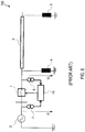
- FIG. 6 shows a basic single-line diagram of a power system 100 that uses a conventional technique for controlling reclosing of a CB.
- the system comprises a power source 2 and a CB 1.
- the CB 1 is arranged to energize and de-energize a transmission line 3.
- the transmission line 3 may be equipped with one or more shunt reactors 4, 9.
- the shunt reactor(s) 4, 9 is/are operative to compensate a capacitance of the transmission line 3.
- Shunt reactor 4 is arranged at the local end of the transmission line, close to the CB 1 and the power source 2.
- Another shunt reactor 9 may be arranged on the far end of the transmission line 3 or in another location along the transmission line 3.
- the healthy phases will generally retain a trapped charge voltage that oscillates at one or more frequencies determined by the parameters of the transmission line 3 and the reactor(s) 4, 9.
- the trapped charge can cause high overvoltages up to 4pu on the transmission line 3.
- the high overvoltages may cause severe stress on an insulation of the transmission line 3.
- the high overvoltages may cause operation of surge arresters.
- Each CB pole can be closed in a beat minimum of the differential voltage across the CB 1.
- a control or protection device 10 can be used to control reclosing of the CB 1.
- the differential voltage across the CB 1 can usually not be measured directly, but has to be calculated as the difference of a source voltage U 1 and a line voltage U 2 . While the source voltage (also referred to as busbar voltage) U 1 can be considered constant in both voltage amplitude and frequency, the voltage U 2 on the transmission line 3 cannot be considered constant in both voltage amplitude and frequency after the CB 1 has tripped, i.e., when a decision on reclosing has to be taken.
- Figure 6 illustrates a conventional control setup for controlled reclosing in which the control or protection device 10 obtains the source voltage U 1 from a source voltage transformer (VT) 7 arranged on the busbar, and the line voltage U 2 from a line VT 5 arranged on the local end of the transmission line 3.
- VT source voltage transformer
- CVTs capacitive voltage transformers
- the transmission line VT 5 may exhibit significant error in both amplitude and phase.
- Conventional techniques that measure the line voltage U 2 using the transmission line VT 5 and calculate the voltage difference across the CB from the difference of the source voltage U 1 measured using the source VT 7 and the line voltage U 2 using the transmission line VT 5 may suffer from inaccurate predictions of the voltage difference across the CB 1 and its beat minima.
- CIGRE WG 13.07 " Controlled Switching of HVAC Circuit Breakers: Guide for Application - Lines, Reactors, Capacitors, Transformers.” 1st part, ÉLECTRA, No. 183, April 1999, pp. 43-73 . 2 nd part," ÉLECTRA, No. 185, August 1999, pp. 37-57 discloses controlled reclosing on shunt compensated transmission lines and discusses the challenge of obtaining a correct image of the line voltage signal U 2 after tripping.
- US 7 936 093 B2 discloses the use of a reactor current and time derivative of a source voltage for obtaining target instants for controlled reclosing. However, the method of US 7 936 093 B2 assumes that zero crossings of the reactor current coincide with zero crossings of the time derivative of a source voltage. Such coincident zero crossings will not necessarily occur in practice, and/or it may take an unacceptably long time for such coincident zero crossings to be observed. The method of US 7 936 093 B2 also assumes that the line frequency is constant, which may not always be the case after CB tripping.
- methods and devices that calculate the line voltage from a time derivative of a current through a shunt reactor.
- Such methods and devices may perform controlled reclosing of a circuit breaker after tripping at a target time at which a difference between a source or busbar voltage U 1 and a derived line voltage calculated as L ⁇ d I L /d t (where L is an inductance of the shunt reactor and I L is a current through the shunt reactor while the circuit breaker is open) is at or near zero or in a beat minimum of the differential voltage calculated as U 1 - L ⁇ d I L /d t.
- the methods and devices may use the value L ⁇ d I L /d t as an estimate for the line voltage of the transmission line for other purposes, such as detecting an instant of line de-energization, detecting an extinction of temporary faults or secondary arcing, at least one protection function, and/or line synchronization.
- the methods and devices according to embodiments may use a current transformer that is connected in series with a shunt reactor, which is arranged between an end of the transmission line and ground, to measure the current through the shunt reactor.
- the current transformer may be an inductive transformer or may comprise a Rogowski coil or a Hall-effect sensor or a similar sensor adapted to measure a current signal. Output signals of the current transformer may be in analog form (such as current or voltage) or streams of digital signals on a process bus. If the current transformer comprises a Rogowski coil, its output voltage, which is by principle the derivative of the current, may be used directly as representation of the line voltage of the transmission line.
- a method of controlling at least one circuit breaker of a power system comprises a power source, a transmission line coupled to the power source through the circuit breaker, a shunt reactor coupled to the transmission line, and a current transformer connected in series with the shunt reactor.
- the method comprises processing an output signal of the current transformer, comprising determining a time derivative of a current sensed by the current transformer.
- the method comprises performing a control and/or protection operation based on the determined time derivative of the current sensed by the current transformer.
- the control and/or protection operation may be performed by at least one control or protection device.
- the control and/or protection operation may be performed automatically by the at least one control or protection device.
- the shunt reactor may be designed to compensate the capacitance of the transmission line by an arbitrary degree, usually in a range from 30 to 80%.
- Processing the output signal of the current transformer may comprise determining a line voltage on the transmission line based on the time derivative of the current sensed by the current transformer.
- the circuit breaker may be a circuit breaker for a transmission line.
- Performing the control and/or protection operation may comprise controlling a reclosing of the circuit breaker after tripping of the circuit breaker.
- the power system may comprise a voltage transformer connected to the power source and adapted to sense a source voltage of the power source or the busbar in at least one phase.
- the at least one control or protection device may control reclosing of the circuit breaker based on an output signal of the voltage transformer and the time derivative of the current sensed by the current transformer.
- the control and/or protection operation may comprise controlling a target reclosing time at which the circuit breaker is reclosed based on the output signal of the voltage transformer and the time derivative of the current sensed by the current transformer.
- the control or protection device may comprise a point-on-wave controller.
- the point-on-wave controller may predict differential voltage signals across the circuit breaker when the circuit breaker is open to identify future beat minima, based on the output signal of the voltage transformer indicative of U 1 and based on the calculated line voltage L ⁇ d I L /d t derived from the time derivative of the shunt reactor current.
- the point-on-wave controller may forward individual reclosing commands to each circuit breaker pole.
- the controlled reclosing may comprise controlling the target closing time such that U 1 - L ⁇ d I L /d t (where U 1 is the source voltage sensed by the voltage transformer, L is an inductance of the shunt reactor, and I L is the current through the shunt reactor while the circuit breaker is open sensed by the current transformer) is at or near zero at the target reclosing time.
- Processing the output signal of the current transformer may comprise multiplying the time derivative of the current sensed by the current transformer by an inductance of the shunt reactor or by another suitable scaling factor.
- the method may further comprise receiving the inductance of the shunt reactor.
- the inductance of the shunt reactor may be received at an interface of the control or protection device.
- the inductance of the shunt reactor may be read from a physical rating plate of the shunt reactor, from a data sheet of the shunt reactor, or from a computerized record representing technical data of the shunt reactor, and may be received at a user interface or data interface of the control or protection device.
- the method may further comprise determining the inductance of the shunt reactor in a calibration that uses the output signal of the voltage transformer measured while the circuit breaker is closed and the time derivative of the current sensed by the current transformer while the circuit breaker is closed.
- the inductance of the shunt reactor may be determined based on at least one peak value, root mean square (RMS) value or other average value of the output signal of the voltage transformer while the circuit breaker is closed and at least one peak value, RMS value or other average value of the time derivative of the current sensed by the current transformer while the circuit breaker is closed.
- RMS root mean square
- the inductance of the shunt reactor may be determined as a quotient of a peak value or RMS value of the output signal of the voltage transformer while the circuit breaker is closed and a peak value or RMS value of the time derivative of the current sensed by the current transformer while the circuit breaker is closed.
- the inductance of the shunt reactor may be determined as a quotient of an average of several peak values or RMS values of the output signal of the voltage transformer while the circuit breaker is closed and an average of several peak values or RMS values of the time derivative of the current sensed by the current transformer while the circuit breaker is closed.
- the method may further comprise using the time derivative of the current sensed by the current transformer to perform one or several of: detecting an instant of line de-energization; detecting an extinction of temporary faults or secondary arcing; at least one protection function; line synchronization.
- the method may be used for plural phases of a power system.
- the method may be used for controlled reclosing on several phases of a power system.
- plural current transformers are provided for the different phases.
- the output signals of the plural current transformers may be processed to determine time derivatives of the current for two or three phases, for example.
- control or protection device may perform the control and/or protection operation based on the determined time derivatives of the currents of the plural phases.
- Performing the control and/or protection operation may comprise performing controlled reclosing of several circuit breakers or circuit breaker poles associated with different phases of the transmission line.
- the controlled reclosing may respectively be performed, for each phase, in dependence on an output voltage of the voltage transformer or a busbar voltage for the respective phase and in dependence on the product of a shunt reactor impedance and the time derivative of the shunt reactor current measured by the current transformer for the respective phase.
- a control or protection device for controlling at least one circuit breaker of a power system comprises a power source, a transmission line coupled to the power source through the circuit breaker, a shunt reactor coupled to the transmission line, and a current transformer connected in series with the shunt reactor.
- the control or protection device comprises an input to receive an input signal representing a current sensed by the current transformer or a time derivative of the current sensed by the current transformer.
- the control or protection device comprises a control circuit adapted to perform a control and/or protection operation based on the time derivative of the current sensed by the current transformer.
- the control or protection device may be adapted to calculate the time derivative of the current sensed by the current transformer.
- the input of the control or protection device may be coupled to a computing device that calculates the time derivative of the current sensed by the current transformer.
- the computing device may further be adapted to multiply the current sensed by the current transformer or the time derivative of that current by a suitable scaling factor such as the inductance of the shunt reactor.
- the control or protection device may comprise a point-on-wave controller.
- the point-on-wave controller may be adapted to control reclosing of a circuit breaker after tripping based on an output signal of a voltage transformer connected to the power source and a line voltage derived from the time derivative of the current sensed by the current transformer.
- the point-on-wave controller may be adapted to predict differential voltage signals across the circuit breaker when the circuit breaker is open to identify future beat minima, based on a source voltage U 1 and based on a calculated line voltage L ⁇ d I L /d t derived from the time derivative of the shunt reactor current.
- the point-on-wave controller may be adapted to control the target closing time such that U 1 - L ⁇ d I L /d t (where U 1 is the source voltage, L is an inductance of the shunt reactor, and I L is the current through the shunt reactor while the circuit breaker is open sensed by the current transformer) is close to zero at the target reclosing time.
- the point-on-wave controller may be adapted to forward individual reclosing commands to each circuit breaker pole.
- the control or protection device may have an interface to receive the inductance of the shunt reactor.
- the inductance of the shunt reactor may be read from a physical rating plate of the shunt reactor, from a data sheet of the shunt reactor, or from a computerized record representing technical data of the shunt reactor, and may be received at a user interface or data interface of the control or protection device.
- the control or protection device may be adapted to determine the inductance of the shunt reactor in a calibration that uses the output signal of the source voltage transformer or load voltage transformer measured while the circuit breaker is closed and the time derivative of the current sensed by the current transformer while the circuit breaker is closed.
- the control or protection device may be adapted to determine the inductance of the shunt reactor based on at least one peak value, RMS value or other average value of the output signal of the source voltage transformer or load voltage transformer while the circuit breaker is closed and at least one peak value, RMS value or other average value of the time derivative of the current sensed by the current transformer while the circuit breaker is closed.
- the control or protection device may be adapted to determine the inductance of the shunt reactor as a quotient of a peak value or RMS value of the output signal of the source voltage transformer or load voltage transformer while the circuit breaker is closed and a peak value or RMS value of the time derivative of the current sensed by the current transformer while the circuit breaker is closed.
- the control or protection device may be adapted to determine the inductance of the shunt reactor as a quotient of an average of several peak values or RMS values of the output signal of the source voltage transformer or load voltage transformer while the circuit breaker is closed and an average of several peak values or RMS values of the time derivative of the current sensed by the current transformer while the circuit breaker is closed.
- control or protection device When used for a power system having plural, e.g. three, phases, the control or protection device may be adapted to determine the inductance of the shunt reactor for each one of the plural phases.
- the control or protection device may be adapted to perform, in any phase or phases of the power system, one or several of: detecting an instant of line de-energization; detecting an extinction of temporary faults or secondary arcing; at least one protection function; line synchronization.
- control or protection device may be adapted to perform the method of any aspect or embodiment of the invention.
- the control or protection device may be adapted to perform controlled reclosing for circuit breakers or circuit breaker poles individually in any one or more phases of a power system.
- plural current transformers can be provided for the different phases.
- the control or protection device may have inputs that are adapted to receive output signals of the plural current transformers that sense a shunt reactor current through shunt reactors of plural different phases of the transmission line.
- the control or protection device may be adapted to effect a controlled reclosing of several circuit breakers or circuit breaker poles associated with different phases of the transmission line.
- the controlled reclosing may respectively be performed, for each phase, in dependence on an output voltage of the voltage transformer or a busbar voltage for the respective phase and in dependence on the product of a shunt reactor impedance and the time derivative of the shunt reactor current measured by the current transformer for the respective phase.
- a power system comprises a power source, a transmission line coupled to the power source through a circuit breaker, a shunt reactor coupled to the transmission line, a current transformer connected in series with a shunt reactor, and the control or protection device according to the invention.
- the shunt reactor may be connected to the local end of the transmission line.
- One or several additional shunt reactors may be connected to the remote end of the transmission line or at other locations.
- the power system may further comprise a computing device adapted to calculate the time derivative of the current sensed by the current transformer.
- the computing device may be adapted to reconstruct a line voltage signal on the transmission line by multiplying the time derivative of the current sensed by the current transformer by an inductance of the shunt reactor or by another suitable scaling factor.
- the current transformer of the power system may comprise a Rogowski coil or a Hall-effect sensor or a similar sensor adapted to measure a current.
- control operations or other operations such as protection operations to be performed in a power network having a transmission line with at least one shunt reactor, without having to rely on potentially inaccurate line voltage measurements in a state in which a circuit breaker has tripped.
- a current transformer typically has a better frequency response than a capacitive voltage transformer.
- the methods and control or protection devices according to embodiments provide increased accuracy of the computed line voltage signal as a basis for a more accurate calculation of a reclosing target, even for different line frequencies.
- Embodiments of the invention may be used for controlled reclosing of a circuit breaker after tripping, without being limited thereto.
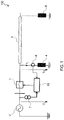
- Figure 1 is a schematic representation of a power system according to an embodiment.
- the power system may be a high voltage power system or a medium voltage power system.
- the power system may comprise a power source 2 and a CB 1.
- the CB 1 is arranged to connect a transmission line 3 to the power source 2 when the CB 1 is closed and to disconnect the transmission line 3 from the power source 2 when the CB 1 is open.
- the transmission line 3 may be equipped with one or more shunt reactors 4, 9.
- the shunt reactor(s) 4, 9 is/are operative to compensate a capacitance of the transmission line 3.
- the shunt reactor 4 is arranged at the local end of the transmission line, close to the CB 1.
- Another shunt reactor 9 may be arranged on the far end of the transmission line 3 or in another location along the transmission line 3, but is not required for the techniques of this disclosure.
- a control or protection device 10 may perform controlled reclosing of the CB 1 after tripping.
- the control or protection device 10 may be or may comprise a point-on-wave controller.
- the control or protection device 10 may be adapted to predict differential voltage signals across the CB 1 when the CB 1 is open to determine a target time for reclosing.
- the control or protection device 10 performs controlled reclosing using a source voltage U 1 and calculated (rather than measured) line voltage L ⁇ d I L /d t derived from a time derivative of a shunt reactor current I L .
- the control or protection device 10 may predict future beat minima at which a voltage difference across the open CB 1 is minimum, based on the measured source voltage U 1 and the calculated line voltage L ⁇ d I L /d t derived from the time derivative of the shunt reactor current I L to determine the target reclosing time of the CB 1.
- the target reclosing time may be determined individually for separate phases or poles of the CB 1.
- the control or protection device 10 may be adapted to forward individual reclosing commands to each circuit breaker pole, in accordance with the predicted future minima of the beat of the voltage difference across the open CB 1.
- the power system 10 may comprise a current transformer 6 connected in series with the shunt reactor 4.
- a series connection of the current transformer 6 and the shunt reactor 4 may be connected between an end of the transmission line 3 and ground.
- the control or protection device 10 may comprise circuitry to calculate the time derivative of the shunt reactor current I L sensed by the current transformer 6.
- the circuitry may comprise an integrated semiconductor circuit such as a processor, controller, or application specific integrated circuit that is programmed to calculate the time derivative.
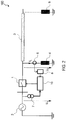
- a separate computing device 8 may be connected between the current transformer 6 and the control or protection device 10. The computing device 8 may compute the time derivative of the shunt reactor current I L sensed by the current transformer 6.
- the computing device 8 may provide the time derivative of the shunt reactor current I L sensed by the current transformer 6, or the reconstructed line voltage signal on the transmission line 3 obtained by multiplying the time derivative of the shunt reactor current I L sensed by the current transformer 6 by an inductance of the shunt reactor 4 or by another suitable scaling factor, to the control or protection device 10.
- the control or protection device 10 or computing device 8 may use the output signal of the current transformer 6 arranged in series with the local shunt reactor 4 to reconstruct the voltage signal U 2 on the local end of the transmission line 3.
- U L L ⁇ dI L dt
- the beat pattern in the differential voltage U CB across the CB 1 may be used by the control or protection device 10 to predict future minima of the beat, e.g., based on the recurring pattern of previous beats in U CB .
- the calculation of the derived line voltage U L can be performed through an analog circuit or numerically, from sampled current values (obtained by the point-on-wave controller itself or via a digital communication system). The calculation can be done by the control or protection device 10, as illustrated in Figure 1 , or by a separate computing device 8 interposed between CT 6 and control or protection device 10, as illustrated in Figure 2 . Instead of the inductance value L in equation (1) a different scaling factor may be applied, for example to match the input ratings of the control or protection device 10.
- the current transformer 6 may comprise a Rogowski coil, which by definition outputs a time derivative of the measured reactor current.
- control or protection device 10 While operation of the control or protection device 10 has been explained with reference to one phase, the power system 10 typically has several phases. A transmission line 3, shunt reactor 4, current transformer 6 and voltage transformer 7 may respectively be provided for each one of the various phases.
- the control or protection device 10 may initiate controlled reclosing of the circuit breaker 1 or of several circuit breaker poles for any of the plural phases that have been tripped, using the techniques described herein.
- Figure 3 shows waveforms 11, 12, 13 of the source voltage U 1 for three different phases, the waveforms 21, 22, 23 of the line voltage U 2 for the three different phases, the waveforms 31, 32, 33 of the reactor current I L for the three different phases, and the waveforms 41, 42, 43 of the calculated line voltage U L determined in accordance with equation (1) from the time derivative of the shunt reactor current.
- the calculated line voltage U L determined in accordance with equation (1) from the time derivative of the shunt reactor current matches the line voltage U 2 that would be obtained from a voltage transformer having good frequency response characteristics.
- the differential voltage U CB across the CB 1 when the CB 1 has tripped, calculated in accordance with equation (2), allows the beat minima of the differential voltage to be predicted with good accuracy.
- Figure 4 is a flow chart of a method 60 according to an embodiment.
- the method 60 may be performed to implement controlled reclosing of the CB 1 after tripping.
- the CB 1 of a power system may be tripped.
- another suitable scaling factor may be applied.
- the differential voltage U CB across the CB 1 after tripping may be determined in accordance with equation (2).
- a beat pattern in the differential voltage U CB across the CB 1 after tripping may be used to predict future minima in U CB .
- controlled reclosing of the CB 1 may be performed using the beat pattern in the differential voltage U CB across the CB 1 after tripping determined in step 63.
- Target reclosing times may be set so that the various poles of the CB 1 are reclosed at beat minima of the differential voltage U CB for the respective phases.
- the inductance L of the shunt reactor 4 may be read from a physical rating plate of the shunt reactor 4, from a data sheet of the shunt reactor 4, or from a computerized record representing technical data of the shunt reactor 4.
- the inductance L may be input into the control or protection device 10, for example, via a user interface or via a data interface.
- a calibration routine may be executed to determine the inductance L of the shunt reactor 4.
- Figure 5 is a flow chart of a method 70 according to an embodiment.
- the method 70 may be performed to determine the inductance L of the shunt reactor 4 in a calibration.
- step 71 the calibration is started.
- the time derivative d I L /d t of the shunt reactor current signal I L measured while the CB 1 is closed may be received or calculated from the shunt reactor current signal I L .
- the source voltage U 1 measured by the VT 7 while the CB 1 is closed may be received.
- the inductance L of the shunt reactor 4 may be calculated based on the source voltage U 1 measured by the VT 7 while the CB 1 is closed and based on the time derivative d I L /d t of the shunt reactor current signal I L measured while the CB 1 is closed.
- the load voltage U 2 measured by the VT 5 may be used while the CB 1 is closed.
- the calculated inductance L of the shunt reactor 4 may be stored in the control or protection device 10 or in the computing device 8, for use in combination with the time derivative d I L /d t of the shunt reactor current signal I L measured while the CB 1 is open to calculate the line voltage U L in accordance with equation (1) for controlled circuit breaker reclosing or for other power system related functions.
- the calibration routine may be performed while the CB 1 is closed.
- the calibration routine may use a source voltage U 1 measured by the VT 7 while the CB 1 is closed and a time derivative of the shunt current signal I L measured by the current transformer 6 while the CB 1 is closed.
- a load voltage U 2 measured by load VT 5 may be used while the CB 1 is closed.
- ⁇ 1 designates a peak value of the source voltage U 1 measured by the VT 7 while the CB 1 is closed
- dI ⁇ dt designates a peak value of the time derivative d I L /d t of the shunt reactor current signal I L measured by the current transformer 6 while the CB 1 is closed.
- peaks of the same polarity are used for both ⁇ 1 and dI ⁇ dt .
- equation (3) may be evaluated by using an average of several peak values of the source voltage U 1 measured by the VT 7, or of the load voltage U 2 measured by the VT 5, while the CB 1 is closed as ⁇ 1 and an average of several peak values of the time derivative of the shunt reactor current signal I L measured by the current transformer 6 while the CB 1 is closed as dI ⁇ dt .
- equation (3) may be evaluated by using the calculated RMS value, or the average of several calculated RMS values, of the source voltage U 1 measured by the VT 7, or of the load voltage U 2 measured by the VT 5, while the CB 1 is closed as ⁇ 1 and the calculated RMS value, or the average of several calculated RMS values, of the shunt reactor current signal I L measured by the current transformer 6 while the CB 1 is closed as dI ⁇ dt .
- Averages other than RMS may be used instead of the RMS values to calculate the inductance L during calibration.
- calibration may be performed for each one of plural different phases of a power system using the techniques described herein to determine the inductances of the shunt reactors of the plural different phases of the transmission line.
- the inductance value calculated in one phase may be applied to all phases, or an inductance value obtained by calculating the average of the inductance values calculated in all phases may be applied to all phases.
- the output signal of the current transformer 6 may be used to calculate the line voltage, obviating the need for using a voltage transformer 7 as in the conventional system illustrated in Figure 6 .
- the time derivative of the shunt reactor current may be used for detecting an instant of line de-energization, for detecting an extinction of temporary faults or secondary arcing, for performing one or several protection functions, and/or for line synchronization (e.g., synchro-check).
- control or protection device While the device 10 is referred to as a "control or protection device” herein, it will be appreciated that the device 10 can perform both control and protection functions.
- the word "or” as used herein is to be understood as being non-exclusive.
Landscapes
- Physics & Mathematics (AREA)
- General Physics & Mathematics (AREA)
- Protection Of Transformers (AREA)
- Emergency Protection Circuit Devices (AREA)
- Driving Mechanisms And Operating Circuits Of Arc-Extinguishing High-Tension Switches (AREA)
- Protection Of Static Devices (AREA)
Abstract
Description
- The invention relates to methods and devices for controlling at least one circuit breaker of a power system. The invention relates in particular to methods and devices that allow at least one circuit breaker of a high or medium voltage system to be controlled. The invention relates in particular to methods and devices for controlled reclosing of at least one circuit breaker of a transmission line.
- Power systems, such as systems for high or medium voltage power transmission, are often equipped with one or several circuit breakers (CBs) to implement control and protection functions. After tripping of a CB, reclosing the CB with an appropriate timing is often desirable to minimize switching transients but may represent a considerable challenge.
-
Figure 6 shows a basic single-line diagram of apower system 100 that uses a conventional technique for controlling reclosing of a CB. The system comprises apower source 2 and aCB 1. TheCB 1 is arranged to energize and de-energize atransmission line 3. Thetransmission line 3 may be equipped with one ormore shunt reactors transmission line 3.Shunt reactor 4 is arranged at the local end of the transmission line, close to theCB 1 and thepower source 2. Anothershunt reactor 9 may be arranged on the far end of thetransmission line 3 or in another location along thetransmission line 3. - On tripping of a
CB 1, the healthy phases will generally retain a trapped charge voltage that oscillates at one or more frequencies determined by the parameters of thetransmission line 3 and the reactor(s) 4, 9. When reclosing theCB 1, the trapped charge can cause high overvoltages up to 4pu on thetransmission line 3. The high overvoltages may cause severe stress on an insulation of thetransmission line 3. The high overvoltages may cause operation of surge arresters. - One way of mitigating the risk of such high overvoltages occuring, is controlled reclosing. Each CB pole can be closed in a beat minimum of the differential voltage across the
CB 1. A control orprotection device 10 can be used to control reclosing of theCB 1. - The differential voltage across the
CB 1 can usually not be measured directly, but has to be calculated as the difference of a source voltage U 1 and a line voltage U 2. While the source voltage (also referred to as busbar voltage) U 1 can be considered constant in both voltage amplitude and frequency, the voltage U 2 on thetransmission line 3 cannot be considered constant in both voltage amplitude and frequency after theCB 1 has tripped, i.e., when a decision on reclosing has to be taken. -
Figure 6 illustrates a conventional control setup for controlled reclosing in which the control orprotection device 10 obtains the source voltage U 1 from a source voltage transformer (VT) 7 arranged on the busbar, and the line voltage U 2 from aline VT 5 arranged on the local end of thetransmission line 3. - However, common designs of voltage transformers are often tuned to nominal power frequency. This applies in particular to capacitive voltage transformers (CVTs). At different frequencies such as those appearing on the
transmission line 3 after CB tripping, thetransmission line VT 5 may exhibit significant error in both amplitude and phase. Conventional techniques that measure the line voltage U 2 using thetransmission line VT 5 and calculate the voltage difference across the CB from the difference of the source voltage U 1 measured using thesource VT 7 and the line voltage U 2 using thetransmission line VT 5 may suffer from inaccurate predictions of the voltage difference across theCB 1 and its beat minima. - CIGRE WG 13.07, "Controlled Switching of HVAC Circuit Breakers: Guide for Application - Lines, Reactors, Capacitors, Transformers." 1st part, ÉLECTRA, No. 183, April 1999, pp. 43-73. 2nd part," ÉLECTRA, No. 185, August 1999, pp. 37-57 discloses controlled reclosing on shunt compensated transmission lines and discusses the challenge of obtaining a correct image of the line voltage signal U 2 after tripping.
-
US 7 936 093 B2 discloses the use of a reactor current and time derivative of a source voltage for obtaining target instants for controlled reclosing. However, the method ofUS 7 936 093 B2 assumes that zero crossings of the reactor current coincide with zero crossings of the time derivative of a source voltage. Such coincident zero crossings will not necessarily occur in practice, and/or it may take an unacceptably long time for such coincident zero crossings to be observed. The method ofUS 7 936 093 B2 also assumes that the line frequency is constant, which may not always be the case after CB tripping. - It is an object of the invention to provide improved methods and devices for performing control and/or protection operations in a power system. It is in particular an object of the invention to provide methods and devices for control and/or protection operations that can be used on transmission lines equipped with one or several shunt reactors and that allow more reliable controlled reclosing of a circuit breaker after tripping. It is in particular an object of the invention to provide methods and control or protection devices for controlled reclosing of a circuit breaker for a transmission line after tripping that can reliably operate without requiring zero crossings of the reactor current to coincide with zero crossings of the time derivative of a source voltage and/or without requiring the line frequency to be constant.
- A method and a device as recited in the independent claims are provided. The dependent claims define embodiments.
- According to embodiments, methods and devices are provided that calculate the line voltage from a time derivative of a current through a shunt reactor. Such methods and devices may perform controlled reclosing of a circuit breaker after tripping at a target time at which a difference between a source or busbar voltage U 1 and a derived line voltage calculated as L · dIL /dt (where L is an inductance of the shunt reactor and IL is a current through the shunt reactor while the circuit breaker is open) is at or near zero or in a beat minimum of the differential voltage calculated as U 1 - L · dIL /dt. The methods and devices may use the value L · dIL /dt as an estimate for the line voltage of the transmission line for other purposes, such as detecting an instant of line de-energization, detecting an extinction of temporary faults or secondary arcing, at least one protection function, and/or line synchronization.
- The methods and devices according to embodiments may use a current transformer that is connected in series with a shunt reactor, which is arranged between an end of the transmission line and ground, to measure the current through the shunt reactor.
- The current transformer may be an inductive transformer or may comprise a Rogowski coil or a Hall-effect sensor or a similar sensor adapted to measure a current signal. Output signals of the current transformer may be in analog form (such as current or voltage) or streams of digital signals on a process bus. If the current transformer comprises a Rogowski coil, its output voltage, which is by principle the derivative of the current, may be used directly as representation of the line voltage of the transmission line.
- A method of controlling at least one circuit breaker of a power system is provided. The power system comprises a power source, a transmission line coupled to the power source through the circuit breaker, a shunt reactor coupled to the transmission line, and a current transformer connected in series with the shunt reactor. The method comprises processing an output signal of the current transformer, comprising determining a time derivative of a current sensed by the current transformer. The method comprises performing a control and/or protection operation based on the determined time derivative of the current sensed by the current transformer.
- The control and/or protection operation may be performed by at least one control or protection device.
- The control and/or protection operation may be performed automatically by the at least one control or protection device.
- The shunt reactor may be designed to compensate the capacitance of the transmission line by an arbitrary degree, usually in a range from 30 to 80%.
- Processing the output signal of the current transformer may comprise determining a line voltage on the transmission line based on the time derivative of the current sensed by the current transformer.
- The circuit breaker may be a circuit breaker for a transmission line. Performing the control and/or protection operation may comprise controlling a reclosing of the circuit breaker after tripping of the circuit breaker.
- The power system may comprise a voltage transformer connected to the power source and adapted to sense a source voltage of the power source or the busbar in at least one phase. The at least one control or protection device may control reclosing of the circuit breaker based on an output signal of the voltage transformer and the time derivative of the current sensed by the current transformer.
- The control and/or protection operation may comprise controlling a target reclosing time at which the circuit breaker is reclosed based on the output signal of the voltage transformer and the time derivative of the current sensed by the current transformer.
- The control or protection device may comprise a point-on-wave controller.
- The point-on-wave controller may predict differential voltage signals across the circuit breaker when the circuit breaker is open to identify future beat minima, based on the output signal of the voltage transformer indicative of U 1 and based on the calculated line voltage L · dIL /dt derived from the time derivative of the shunt reactor current.
- The point-on-wave controller may forward individual reclosing commands to each circuit breaker pole.
- The controlled reclosing may comprise controlling the target closing time such that U 1 - L · dIL /dt (where U 1 is the source voltage sensed by the voltage transformer, L is an inductance of the shunt reactor, and IL is the current through the shunt reactor while the circuit breaker is open sensed by the current transformer) is at or near zero at the target reclosing time.
- Processing the output signal of the current transformer may comprise multiplying the time derivative of the current sensed by the current transformer by an inductance of the shunt reactor or by another suitable scaling factor.
- The method may further comprise receiving the inductance of the shunt reactor. The inductance of the shunt reactor may be received at an interface of the control or protection device. The inductance of the shunt reactor may be read from a physical rating plate of the shunt reactor, from a data sheet of the shunt reactor, or from a computerized record representing technical data of the shunt reactor, and may be received at a user interface or data interface of the control or protection device.
- The method may further comprise determining the inductance of the shunt reactor in a calibration that uses the output signal of the voltage transformer measured while the circuit breaker is closed and the time derivative of the current sensed by the current transformer while the circuit breaker is closed.
- The inductance of the shunt reactor may be determined based on at least one peak value, root mean square (RMS) value or other average value of the output signal of the voltage transformer while the circuit breaker is closed and at least one peak value, RMS value or other average value of the time derivative of the current sensed by the current transformer while the circuit breaker is closed.
- The inductance of the shunt reactor may be determined as a quotient of a peak value or RMS value of the output signal of the voltage transformer while the circuit breaker is closed and a peak value or RMS value of the time derivative of the current sensed by the current transformer while the circuit breaker is closed.
- The inductance of the shunt reactor may be determined as a quotient of an average of several peak values or RMS values of the output signal of the voltage transformer while the circuit breaker is closed and an average of several peak values or RMS values of the time derivative of the current sensed by the current transformer while the circuit breaker is closed.
- The method may further comprise using the time derivative of the current sensed by the current transformer to perform one or several of: detecting an instant of line de-energization; detecting an extinction of temporary faults or secondary arcing; at least one protection function; line synchronization.
- The method may be used for plural phases of a power system. For illustration, the method may be used for controlled reclosing on several phases of a power system. In a power system with plural phases, plural current transformers are provided for the different phases. The output signals of the plural current transformers may be processed to determine time derivatives of the current for two or three phases, for example.
- In the method, the control or protection device may perform the control and/or protection operation based on the determined time derivatives of the currents of the plural phases.
- Performing the control and/or protection operation may comprise performing controlled reclosing of several circuit breakers or circuit breaker poles associated with different phases of the transmission line. The controlled reclosing may respectively be performed, for each phase, in dependence on an output voltage of the voltage transformer or a busbar voltage for the respective phase and in dependence on the product of a shunt reactor impedance and the time derivative of the shunt reactor current measured by the current transformer for the respective phase.
- A control or protection device for controlling at least one circuit breaker of a power system is provided. The power system comprises a power source, a transmission line coupled to the power source through the circuit breaker, a shunt reactor coupled to the transmission line, and a current transformer connected in series with the shunt reactor. The control or protection device comprises an input to receive an input signal representing a current sensed by the current transformer or a time derivative of the current sensed by the current transformer. The control or protection device comprises a control circuit adapted to perform a control and/or protection operation based on the time derivative of the current sensed by the current transformer.
- The control or protection device may be adapted to calculate the time derivative of the current sensed by the current transformer.
- The input of the control or protection device may be coupled to a computing device that calculates the time derivative of the current sensed by the current transformer.
- The computing device may further be adapted to multiply the current sensed by the current transformer or the time derivative of that current by a suitable scaling factor such as the inductance of the shunt reactor.
- The control or protection device may comprise a point-on-wave controller.
- The point-on-wave controller may be adapted to control reclosing of a circuit breaker after tripping based on an output signal of a voltage transformer connected to the power source and a line voltage derived from the time derivative of the current sensed by the current transformer.
- The point-on-wave controller may be adapted to predict differential voltage signals across the circuit breaker when the circuit breaker is open to identify future beat minima, based on a source voltage U 1 and based on a calculated line voltage L · dIL /dt derived from the time derivative of the shunt reactor current.
- The point-on-wave controller may be adapted to control the target closing time such that U 1 - L · dIL /dt (where U 1 is the source voltage, L is an inductance of the shunt reactor, and IL is the current through the shunt reactor while the circuit breaker is open sensed by the current transformer) is close to zero at the target reclosing time.
- The point-on-wave controller may be adapted to forward individual reclosing commands to each circuit breaker pole.
- The control or protection device may have an interface to receive the inductance of the shunt reactor. The inductance of the shunt reactor may be read from a physical rating plate of the shunt reactor, from a data sheet of the shunt reactor, or from a computerized record representing technical data of the shunt reactor, and may be received at a user interface or data interface of the control or protection device.
- The control or protection device may be adapted to determine the inductance of the shunt reactor in a calibration that uses the output signal of the source voltage transformer or load voltage transformer measured while the circuit breaker is closed and the time derivative of the current sensed by the current transformer while the circuit breaker is closed.
- The control or protection device may be adapted to determine the inductance of the shunt reactor based on at least one peak value, RMS value or other average value of the output signal of the source voltage transformer or load voltage transformer while the circuit breaker is closed and at least one peak value, RMS value or other average value of the time derivative of the current sensed by the current transformer while the circuit breaker is closed.
- The control or protection device may be adapted to determine the inductance of the shunt reactor as a quotient of a peak value or RMS value of the output signal of the source voltage transformer or load voltage transformer while the circuit breaker is closed and a peak value or RMS value of the time derivative of the current sensed by the current transformer while the circuit breaker is closed.
- The control or protection device may be adapted to determine the inductance of the shunt reactor as a quotient of an average of several peak values or RMS values of the output signal of the source voltage transformer or load voltage transformer while the circuit breaker is closed and an average of several peak values or RMS values of the time derivative of the current sensed by the current transformer while the circuit breaker is closed.
- When used for a power system having plural, e.g. three, phases, the control or protection device may be adapted to determine the inductance of the shunt reactor for each one of the plural phases.
- The control or protection device may be adapted to perform, in any phase or phases of the power system, one or several of: detecting an instant of line de-energization; detecting an extinction of temporary faults or secondary arcing; at least one protection function; line synchronization.
- The control or protection device may be adapted to perform the method of any aspect or embodiment of the invention.
- The control or protection device may be adapted to perform controlled reclosing for circuit breakers or circuit breaker poles individually in any one or more phases of a power system. In a power system with plural phases, plural current transformers can be provided for the different phases.
- The control or protection device may have inputs that are adapted to receive output signals of the plural current transformers that sense a shunt reactor current through shunt reactors of plural different phases of the transmission line.
- The control or protection device may be adapted to effect a controlled reclosing of several circuit breakers or circuit breaker poles associated with different phases of the transmission line. The controlled reclosing may respectively be performed, for each phase, in dependence on an output voltage of the voltage transformer or a busbar voltage for the respective phase and in dependence on the product of a shunt reactor impedance and the time derivative of the shunt reactor current measured by the current transformer for the respective phase.
- A power system according to an embodiment comprises a power source, a transmission line coupled to the power source through a circuit breaker, a shunt reactor coupled to the transmission line, a current transformer connected in series with a shunt reactor, and the control or protection device according to the invention.
- The shunt reactor may be connected to the local end of the transmission line. One or several additional shunt reactors may be connected to the remote end of the transmission line or at other locations.
- The power system may further comprise a computing device adapted to calculate the time derivative of the current sensed by the current transformer.
- The computing device may be adapted to reconstruct a line voltage signal on the transmission line by multiplying the time derivative of the current sensed by the current transformer by an inductance of the shunt reactor or by another suitable scaling factor.
- The current transformer of the power system may comprise a Rogowski coil or a Hall-effect sensor or a similar sensor adapted to measure a current.
- The method, control or protection device, and system according to embodiments allow control operations or other operations such as protection operations to be performed in a power network having a transmission line with at least one shunt reactor, without having to rely on potentially inaccurate line voltage measurements in a state in which a circuit breaker has tripped.
- A current transformer typically has a better frequency response than a capacitive voltage transformer. The methods and control or protection devices according to embodiments provide increased accuracy of the computed line voltage signal as a basis for a more accurate calculation of a reclosing target, even for different line frequencies.
- Embodiments of the invention may be used for controlled reclosing of a circuit breaker after tripping, without being limited thereto.
- The subject-matter of the invention will be explained in more detail with reference to preferred exemplary embodiments which are illustrated in the attached drawings, in which:
-
Figure 1 is a schematic representation of a power system comprising a control or protection device according to an embodiment. -
Figure 2 is a schematic representation of a power system comprising a control or protection device according to an embodiment, wherein a computing device separate from the control or protection device is provided. -
Figure 3 illustrates signals for different phases of a power system. -
Figure 4 is a flow chart of a method according to an embodiment. -
Figure 5 is a flow chart of a method that comprises a calibration according to an embodiment. -
Figure 6 is a schematic representation of a power system employing a conventional control structure for controlled reclosing. - Exemplary embodiments of the invention will be described with reference to the drawings in which identical or similar reference signs designate identical or similar elements. While some embodiments will be described in the context of controlled reclosing of a circuit breaker (CB) after tripping, the embodiments are not limited thereto. The features of embodiments may be combined with each other, unless specifically noted otherwise.
- While the power system and its components are described and shown in single-phase representation, it is generally to be understood that a power system and its components usually comprise three phases. However, the invention with its embodiments is not limited to a specific number of system phases.
-
Figure 1 is a schematic representation of a power system according to an embodiment. The power system may be a high voltage power system or a medium voltage power system. - The power system may comprise a
power source 2 and aCB 1. TheCB 1 is arranged to connect atransmission line 3 to thepower source 2 when theCB 1 is closed and to disconnect thetransmission line 3 from thepower source 2 when theCB 1 is open. Thetransmission line 3 may be equipped with one ormore shunt reactors transmission line 3. Theshunt reactor 4 is arranged at the local end of the transmission line, close to theCB 1. Anothershunt reactor 9 may be arranged on the far end of thetransmission line 3 or in another location along thetransmission line 3, but is not required for the techniques of this disclosure. - A control or
protection device 10 may perform controlled reclosing of theCB 1 after tripping. The control orprotection device 10 may be or may comprise a point-on-wave controller. The control orprotection device 10 may be adapted to predict differential voltage signals across theCB 1 when theCB 1 is open to determine a target time for reclosing. - Contrary to conventional control strategies that use a
voltage transformer 5 for directly measuring a line voltage U 2 for identifying future beat minima (as illustrated inFigure 6 and as explained above), the control orprotection device 10 performs controlled reclosing using a source voltage U 1 and calculated (rather than measured) line voltage L · dIL /dt derived from a time derivative of a shunt reactor current IL . The control orprotection device 10 may predict future beat minima at which a voltage difference across theopen CB 1 is minimum, based on the measured source voltage U 1 and the calculated line voltage L · dIL /dt derived from the time derivative of the shunt reactor current IL to determine the target reclosing time of theCB 1. The target reclosing time may be determined individually for separate phases or poles of theCB 1. The control orprotection device 10 may be adapted to forward individual reclosing commands to each circuit breaker pole, in accordance with the predicted future minima of the beat of the voltage difference across theopen CB 1. - In order to provide the shunt reactor current, the
power system 10 may comprise acurrent transformer 6 connected in series with theshunt reactor 4. A series connection of thecurrent transformer 6 and theshunt reactor 4 may be connected between an end of thetransmission line 3 and ground. - The control or
protection device 10 may comprise circuitry to calculate the time derivative of the shunt reactor current IL sensed by thecurrent transformer 6. The circuitry may comprise an integrated semiconductor circuit such as a processor, controller, or application specific integrated circuit that is programmed to calculate the time derivative. In another embodiment, as illustrated inFigure 2 , aseparate computing device 8 may be connected between thecurrent transformer 6 and the control orprotection device 10. Thecomputing device 8 may compute the time derivative of the shunt reactor current IL sensed by thecurrent transformer 6. Thecomputing device 8 may provide the time derivative of the shunt reactor current IL sensed by thecurrent transformer 6, or the reconstructed line voltage signal on thetransmission line 3 obtained by multiplying the time derivative of the shunt reactor current IL sensed by thecurrent transformer 6 by an inductance of theshunt reactor 4 or by another suitable scaling factor, to the control orprotection device 10. - The control or
protection device 10 orcomputing device 8 may use the output signal of thecurrent transformer 6 arranged in series with thelocal shunt reactor 4 to reconstruct the voltage signal U 2 on the local end of thetransmission line 3. According to the basic electrical equation of a reactor,
Figure 3 , which reflect that U 2 = UL. - The differential voltage UCB across the
CB 1 after tripping may be determined using the calculated voltage UL,
- The beat pattern in the differential voltage UCB across the
CB 1 may be used by the control orprotection device 10 to predict future minima of the beat, e.g., based on the recurring pattern of previous beats in UCB. - The calculation of the derived line voltage UL can be performed through an analog circuit or numerically, from sampled current values (obtained by the point-on-wave controller itself or via a digital communication system). The calculation can be done by the control or
protection device 10, as illustrated inFigure 1 , or by aseparate computing device 8 interposed betweenCT 6 and control orprotection device 10, as illustrated inFigure 2 . Instead of the inductance value L in equation (1) a different scaling factor may be applied, for example to match the input ratings of the control orprotection device 10. - The
current transformer 6 may comprise a Rogowski coil, which by definition outputs a time derivative of the measured reactor current. In such an embodiment, the step of calculating the derivative of the shunt reactor current signal IL is implicitly included in the measurement of the shunt reactor current signal, and the derived line voltage signal U 2 = UL is obtained simply by appropriate scaling of the output signal of the Rogowski coil, for example to satisfyequation 1. - While operation of the control or
protection device 10 has been explained with reference to one phase, thepower system 10 typically has several phases. Atransmission line 3, shuntreactor 4,current transformer 6 andvoltage transformer 7 may respectively be provided for each one of the various phases. The control orprotection device 10 may initiate controlled reclosing of thecircuit breaker 1 or of several circuit breaker poles for any of the plural phases that have been tripped, using the techniques described herein. -
Figure 3 showswaveforms waveforms waveforms waveforms Figure 3 , the calculated line voltage UL determined in accordance with equation (1) from the time derivative of the shunt reactor current matches the line voltage U 2 that would be obtained from a voltage transformer having good frequency response characteristics. The differential voltage UCB across theCB 1 when theCB 1 has tripped, calculated in accordance with equation (2), allows the beat minima of the differential voltage to be predicted with good accuracy. -
Current transformers 6 usually have a better frequency response thancapacitive voltage transformers 5. Hence, the accuracy of the derived line voltage signal UL determined in accordance with equation (1) is suitable for calculating a correct reclosing target, even at line frequencies significantly different from nominal power frequency. -
Figure 4 is a flow chart of amethod 60 according to an embodiment. Themethod 60 may be performed to implement controlled reclosing of theCB 1 after tripping. - At
step 61, theCB 1 of a power system may be tripped. - At
step 62, the time derivative of the shunt current signal IL measured while theCB 1 is open may be calculated and multiplied by the inductance L of the shunt reactor, in accordance with equation (1), to yield a voltage that is equal to the line voltage signal U 2 = UL. Instead of the inductance value L, another suitable scaling factor may be applied. - At
step 63, the differential voltage UCB across theCB 1 after tripping may be determined in accordance with equation (2). A beat pattern in the differential voltage UCB across theCB 1 after tripping may be used to predict future minima in UCB. - At
step 64, controlled reclosing of theCB 1 may be performed using the beat pattern in the differential voltage UCB across theCB 1 after tripping determined instep 63. Target reclosing times may be set so that the various poles of theCB 1 are reclosed at beat minima of the differential voltage UCB for the respective phases. - The inductance L of the
shunt reactor 4 may be read from a physical rating plate of theshunt reactor 4, from a data sheet of theshunt reactor 4, or from a computerized record representing technical data of theshunt reactor 4. The inductance L may be input into the control orprotection device 10, for example, via a user interface or via a data interface. - Alternatively or additionally, a calibration routine may be executed to determine the inductance L of the
shunt reactor 4. -
Figure 5 is a flow chart of amethod 70 according to an embodiment. Themethod 70 may be performed to determine the inductance L of theshunt reactor 4 in a calibration. - At
step 71, the calibration is started. - At
step 72, the time derivative dIL /dt of the shunt reactor current signal IL measured while theCB 1 is closed may be received or calculated from the shunt reactor current signal IL. - At
step 73, the source voltage U 1 measured by theVT 7 while theCB 1 is closed may be received. - At
step 74, the inductance L of theshunt reactor 4 may be calculated based on the source voltage U 1 measured by theVT 7 while theCB 1 is closed and based on the time derivative dIL /dt of the shunt reactor current signal IL measured while theCB 1 is closed. Instead of the source voltage U 1 measured by theVT 7, the load voltage U 2 measured by theVT 5 may be used while theCB 1 is closed. - At
step 75, the calculated inductance L of theshunt reactor 4 may be stored in the control orprotection device 10 or in thecomputing device 8, for use in combination with the time derivative dIL /dt of the shunt reactor current signal IL measured while theCB 1 is open to calculate the line voltage UL in accordance with equation (1) for controlled circuit breaker reclosing or for other power system related functions. - The calibration routine may be performed while the
CB 1 is closed. The calibration routine may use a source voltage U 1 measured by theVT 7 while theCB 1 is closed and a time derivative of the shunt current signal IL measured by thecurrent transformer 6 while theCB 1 is closed. Instead of the source voltage U 1 measured by theVT 7, a load voltage U 2 measured byload VT 5 may be used while theCB 1 is closed. - In the calibration routine, the inductance L may be determined as

VT 7 while theCB 1 is closed and
current transformer 6 while theCB 1 is closed. In equation (3) peaks of the same polarity are used for both Û 1 and
- Instead of using a single peak value, equation (3) may be evaluated by using an average of several peak values of the source voltage U 1 measured by the
VT 7, or of the load voltage U 2 measured by theVT 5, while theCB 1 is closed as Û 1 and an average of several peak values of the time derivative of the shunt reactor current signal IL measured by thecurrent transformer 6 while theCB 1 is closed as
VT 7, or of the load voltage U 2 measured by theVT 5, while theCB 1 is closed as Û 1 and the calculated RMS value, or the average of several calculated RMS values, of the shunt reactor current signal IL measured by thecurrent transformer 6 while theCB 1 is closed as
- While a calibration has been explained with reference to one phase, calibration may be performed for each one of plural different phases of a power system using the techniques described herein to determine the inductances of the shunt reactors of the plural different phases of the transmission line. Alternatively, the inductance value calculated in one phase may be applied to all phases, or an inductance value obtained by calculating the average of the inductance values calculated in all phases may be applied to all phases.
- While embodiments of the invention have been described in association with controlled reclosing of a circuit breaker after tripping, the methods, devices, and systems may be used for other purposes. For illustration, the output signal of the
current transformer 6 may be used to calculate the line voltage, obviating the need for using avoltage transformer 7 as in the conventional system illustrated inFigure 6 . The time derivative of the shunt reactor current may be used for detecting an instant of line de-energization, for detecting an extinction of temporary faults or secondary arcing, for performing one or several protection functions, and/or for line synchronization (e.g., synchro-check). - While the
device 10 is referred to as a "control or protection device" herein, it will be appreciated that thedevice 10 can perform both control and protection functions. The word "or" as used herein is to be understood as being non-exclusive. - While peak values or RMS values of various signals have been described herein in the context of techniques for determining the inductance value of the shunt reactor, other values that are characteristic for a voltage amplitude and an amplitude of a time derivative may be used in the disclosed procedures.
- While the invention has been described in detail in the drawings and foregoing description, such description is to be considered illustrative or exemplary and not restrictive. Variations to the disclosed embodiments can be understood and effected by those skilled in the art and practicing the claimed invention, from a study of the drawings, the disclosure, and the appended claims. In the claims, the word "comprising" does not exclude other elements or steps, and the indefinite article "a" or "an" does not exclude a plurality. The mere fact that certain elements or steps are recited in distinct claims does not indicate that a combination of these elements or steps cannot be used to advantage; specifically, in addition to the actual claim dependency, any further meaningful claim combination shall be considered disclosed.
Claims (15)
- A method of controlling at least one circuit breaker (1) of a power system (100), the power system (100) further comprising a power source (2), a transmission line (3) coupled to the power source (2) through the circuit breaker (1), a shunt reactor (4) coupled to the transmission line (3), and a current transformer (6) connected in series with the shunt reactor (4), the method comprising:processing an output signal of the current transformer (6), comprising determining a time derivative of a current (IL ) sensed by the current transformer (6); andperforming a control and/or protection operation based on the determined time derivative of the current (IL ) sensed by the current transformer (6).
- The method of claim 1, wherein processing the output signal of the current transformer (6) comprises determining a line voltage (U 2) on the transmission line (3) based on the time derivative of the current (IL ) sensed by the current transformer (6).
- The method of claim 1 or claim 2, wherein the control and/or protection operation comprises a controlled reclosing of the circuit breaker (1) after tripping of the circuit breaker (1).
- The method of claim 3, wherein the power system comprises a voltage transformer (7) connected to the power source (2) and adapted to sense a source voltage (U 1) of the power source (2), wherein the control and/or protection operation comprises a controlled reclosing of the circuit breaker (1) based on an output signal of the voltage transformer (7) and on the time derivative of the current (IL ) sensed by the current transformer (6).
- The method of claim 4, wherein the controlled reclosing of the circuit breaker (1) comprises controlling a target reclosing time at which the circuit breaker (1) is reclosed based on the output signal of the voltage transformer (7) and on the time derivative of the current (IL ) sensed by the current transformer (6).
- The method of any one of claims 3 to 5, wherein the reclosing of the circuit breaker (1) is controlled by a control or protection device (10) comprising a point-on-wave controller.
- The method of any one of the preceding claims, wherein processing the output signal of the current transformer (6) comprises determining a line voltage on the transmission line (3) by multiplying the time derivative of the current (IL ) sensed by the current transformer (6) by an inductance of the shunt reactor (4) or by another suitable scaling factor.
- The method of claim 7 when dependent on any one of claims 4 to 6, further comprising determining the inductance of the shunt reactor (4) in a calibration that uses the output signal of the voltage transformer (7) measured while the circuit breaker (1) is closed and the time derivative of the current (IL ) sensed by the current transformer (6) while the circuit breaker (1) is closed.
- The method of claim 8, wherein the inductance of the shunt reactor (4) is determined based on at least one peak value of the output signal of the voltage transformer (7) while the circuit breaker (1) is closed and at least one peak value of the time derivative of the current (IL ) sensed by the current transformer (6) while the circuit breaker (1) is closed, or
wherein the inductance of the shunt reactor (4) is determined based on at least one calculated root mean square, RMS, value of the output signal of the voltage transformer (7) while the circuit breaker (1) is closed and at least one calculated RMS value of the time derivative of the current (IL ) sensed by the current transformer (6) while the circuit breaker (1) is closed. - The method of any one of the preceding claims, further comprising using the time derivative of the current (IL ) sensed by the current transformer (6) to perform at least one of:- detecting an instant of line de-energization;- detecting an extinction of temporary faults or secondary arcing;- at least one protection function;- line synchronization.
- A control or protection device (10) for controlling at least one circuit breaker (1) of a power system, the power system further comprising a power source (2), a transmission line (3) coupled to the power source (2) through the circuit breaker (1), a shunt reactor (4) coupled to the transmission line (3), and a current transformer (6) connected in series with the shunt reactor (4),
wherein the control or protection device (10) comprises:an input to receive an input signal representing a current (IL ) sensed by the current transformer (6) or a time derivative of the current (IL ) sensed by the current transformer (6); anda control circuit adapted to perform a control and/or protection operation based on the time derivative of the current (IL ) sensed by the current transformer (6). - The control or protection device (10) of claim 11, wherein the control or protection device (10) comprises a point-on-wave controller adapted to perform controlled reclosing of a circuit breaker (1) after tripping based on an output signal of a voltage transformer (7) connected to the power source (2) and on a line voltage signal derived from the time derivative of the current (IL ) sensed by the current transformer (6).
- The control or protection device (10) of claim 11 or claim 12, wherein the control or protection device (10) is adapted to perform the method of any one of claims 1 to 10.
- A power system (100), comprising:a power source (2),a transmission line (3) coupled to the power source (2) through a circuit breaker (1),a shunt reactor (4) coupled to the transmission line (3),a current transformer (6) connected in series with the shunt reactor (4), andthe control or protection device (10) of any one of claims 11 to 13.
- The power system of claim 14, further comprising a computing device (8) adapted to calculate the time derivative of the current (IL ) sensed by the current transformer (6),
optionally wherein the computing device (8) is adapted to reconstruct a line voltage signal on the transmission line (3) by multiplying the time derivative of the current (IL ) sensed by the current transformer (6) by an inductance of the shunt reactor (4) or by another suitable scaling factor.
Priority Applications (5)
| Application Number | Priority Date | Filing Date | Title |
|---|---|---|---|
| US17/278,802 US11757282B2 (en) | 2018-09-28 | 2019-09-24 | Method and device for controlling at least one circuit breaker of a power system |
| JP2021517387A JP7214854B2 (en) | 2018-09-28 | 2019-09-24 | Method and apparatus for controlling at least one circuit breaker in an electrical power system |
| CN201980061082.1A CN112703649B (en) | 2018-09-28 | 2019-09-24 | Method and device for controlling at least one circuit breaker of an electric power system |
| PCT/EP2019/075651 WO2020064699A1 (en) | 2018-09-28 | 2019-09-24 | Method and device for controlling at least one circuit breaker of a power system |
| CA3114019A CA3114019C (en) | 2018-09-28 | 2019-09-24 | Method and device for controlling at least one circuit breaker of a power system |
Applications Claiming Priority (1)
| Application Number | Priority Date | Filing Date | Title |
|---|---|---|---|
| IN201841036616 | 2018-09-28 |
Publications (2)
| Publication Number | Publication Date |
|---|---|
| EP3629437A1 true EP3629437A1 (en) | 2020-04-01 |
| EP3629437B1 EP3629437B1 (en) | 2023-08-02 |
Family
ID=63832325
Family Applications (1)
| Application Number | Title | Priority Date | Filing Date |
|---|---|---|---|
| EP18199596.0A Active EP3629437B1 (en) | 2018-09-28 | 2018-10-10 | Method and device for controlling at least one circuit breaker of a power system |
Country Status (6)
| Country | Link |
|---|---|
| US (1) | US11757282B2 (en) |
| EP (1) | EP3629437B1 (en) |
| JP (1) | JP7214854B2 (en) |
| CN (1) | CN112703649B (en) |
| CA (1) | CA3114019C (en) |
| WO (1) | WO2020064699A1 (en) |
Cited By (3)
| Publication number | Priority date | Publication date | Assignee | Title |
|---|---|---|---|---|
| EP3916939A1 (en) * | 2020-05-25 | 2021-12-01 | Siemens Aktiengesellschaft | Method for line protection and protection arrangement |
| US11437205B2 (en) * | 2018-12-27 | 2022-09-06 | Hitachi Energy Switzerland Ag | Method and device for monitoring operation of a switching device for controlled switching applications |
| EP4481978A1 (en) * | 2023-06-22 | 2024-12-25 | Kries-Energietechnik GmbH & Co. KG | Apparatus and method for voltage compensated disconnector control based on calibration |
Families Citing this family (3)
| Publication number | Priority date | Publication date | Assignee | Title |
|---|---|---|---|---|
| KR20250086620A (en) * | 2022-10-11 | 2025-06-13 | 에스 앤드 시이 일렉트릭 캄파니 | A method for detecting polarity at points on a wave for saturation relief |
| CN116845836A (en) * | 2023-05-25 | 2023-10-03 | 中国长江电力股份有限公司 | Optical fiber differential protection system and protection method for adaptive multi-segment complex transmission path lines |
| CN116702630B (en) * | 2023-08-07 | 2023-11-10 | 国网安徽省电力有限公司营销服务中心 | Error iterative evaluation method for capacitive voltage transformer CVT |
Citations (5)
| Publication number | Priority date | Publication date | Assignee | Title |
|---|---|---|---|---|
| DE19612992A1 (en) * | 1996-03-22 | 1997-09-25 | Siemens Ag | Fault detection on section of power line between power switches |
| JP2004349001A (en) * | 2003-05-20 | 2004-12-09 | Mitsubishi Electric Corp | Circuit breaker |
| US20080123234A1 (en) * | 2006-11-28 | 2008-05-29 | Mitsubishi Electric Corporation | Switchgear control apparatus |
| US7936093B2 (en) | 2007-02-15 | 2011-05-03 | Mitsubishi Electric Corporation | Phase control switching device |
| US20130234731A1 (en) * | 2012-03-09 | 2013-09-12 | Demetrios A. Tziouvaras | Systems and methods for determining trapped transmission line charge |
Family Cites Families (16)
| Publication number | Priority date | Publication date | Assignee | Title |
|---|---|---|---|---|
| US4377833A (en) * | 1981-08-17 | 1983-03-22 | Electric Power Research Institute, Inc. | Methods and apparatus for protecting electrical reactors |
| JPS6051408A (en) * | 1983-08-31 | 1985-03-22 | 株式会社日立製作所 | Protecting relaying method |
| JPS60151408A (en) | 1984-01-19 | 1985-08-09 | 株式会社リケン | Connecting structure of tubular member and tabular member and method of connecting said member |
| TR200003395T2 (en) | 1998-05-19 | 2001-03-21 | Sure Power Corporation | Energy system. |
| FR2853466B1 (en) * | 2003-04-02 | 2005-05-06 | Alstom | METHOD FOR DETERMINING THE CLOSURE TIME OF A CIRCUIT BREAKER ON A HIGH VOLTAGE LINE |
| DE102005005228A1 (en) | 2005-01-31 | 2006-08-31 | Siemens Ag | Method and device for determining a switching time of an electrical switching device |
| US8032260B2 (en) | 2005-11-30 | 2011-10-04 | General Electric Company | Method and system for controlling a power distribution system |
| WO2008057386A2 (en) | 2006-11-01 | 2008-05-15 | Carling Technologies, Inc. | Remote power management and monitoring system for solid state circuit breaker control with manual bypass |
| JP5472912B2 (en) * | 2010-02-19 | 2014-04-16 | 株式会社東芝 | Overvoltage suppression device |
| US9214718B2 (en) | 2012-03-08 | 2015-12-15 | Apple Inc. | Methods for characterizing tunable radio-frequency elements |
| US10320177B2 (en) | 2012-12-13 | 2019-06-11 | Emneve Pty Limited | Power distribution system and method, and circuit breaker for use therein |
| US9618586B2 (en) * | 2013-02-12 | 2017-04-11 | Abb Schweiz Ag | Method and device for detection of a fault in a protected unit |
| US8744637B1 (en) * | 2013-09-12 | 2014-06-03 | Deepak Maragal | Methods and apparatus for detecting the clearance of fault in shunt reactor compensated transmission lines |
| CN103795082B (en) * | 2014-02-13 | 2015-09-09 | 辽宁立德电力电子股份有限公司 | A kind of distributed power source connects net controller and control method |
| US9659721B1 (en) | 2014-05-06 | 2017-05-23 | Google Inc. | Circuit breakers with integrated safety, control, monitoring, and protection features |
| WO2016084055A1 (en) * | 2014-11-30 | 2016-06-02 | Abb Technology Ltd. | A method for estimating an electrical operating time of a circuit breaker using current feedback |
-
2018
- 2018-10-10 EP EP18199596.0A patent/EP3629437B1/en active Active
-
2019
- 2019-09-24 JP JP2021517387A patent/JP7214854B2/en active Active
- 2019-09-24 US US17/278,802 patent/US11757282B2/en active Active
- 2019-09-24 WO PCT/EP2019/075651 patent/WO2020064699A1/en not_active Ceased
- 2019-09-24 CA CA3114019A patent/CA3114019C/en active Active
- 2019-09-24 CN CN201980061082.1A patent/CN112703649B/en active Active
Patent Citations (5)
| Publication number | Priority date | Publication date | Assignee | Title |
|---|---|---|---|---|
| DE19612992A1 (en) * | 1996-03-22 | 1997-09-25 | Siemens Ag | Fault detection on section of power line between power switches |
| JP2004349001A (en) * | 2003-05-20 | 2004-12-09 | Mitsubishi Electric Corp | Circuit breaker |
| US20080123234A1 (en) * | 2006-11-28 | 2008-05-29 | Mitsubishi Electric Corporation | Switchgear control apparatus |
| US7936093B2 (en) | 2007-02-15 | 2011-05-03 | Mitsubishi Electric Corporation | Phase control switching device |
| US20130234731A1 (en) * | 2012-03-09 | 2013-09-12 | Demetrios A. Tziouvaras | Systems and methods for determining trapped transmission line charge |
Non-Patent Citations (2)
| Title |
|---|
| "Controlled Switching of HVAC Circuit Breakers: Guide for Application - Lines, Reactors, Capacitors, Transformers", ELECTRA, April 1999 (1999-04-01), pages 43 - 73 |
| ELECTRA, August 1999 (1999-08-01), pages 37 - 57 |
Cited By (5)
| Publication number | Priority date | Publication date | Assignee | Title |
|---|---|---|---|---|
| US11437205B2 (en) * | 2018-12-27 | 2022-09-06 | Hitachi Energy Switzerland Ag | Method and device for monitoring operation of a switching device for controlled switching applications |
| EP3916939A1 (en) * | 2020-05-25 | 2021-12-01 | Siemens Aktiengesellschaft | Method for line protection and protection arrangement |
| CN113794181A (en) * | 2020-05-25 | 2021-12-14 | 西门子股份公司 | Method and protective device for line protection |
| US11705722B2 (en) | 2020-05-25 | 2023-07-18 | Siemens Aktiengesellschaft | Method for protecting lines in which a reactor device for reactive power compensation is provided on an electrical line and protection assembly including a reactor device for reactive power compensation |
| EP4481978A1 (en) * | 2023-06-22 | 2024-12-25 | Kries-Energietechnik GmbH & Co. KG | Apparatus and method for voltage compensated disconnector control based on calibration |
Also Published As
| Publication number | Publication date |
|---|---|
| CN112703649A (en) | 2021-04-23 |
| US11757282B2 (en) | 2023-09-12 |
| CN112703649B (en) | 2024-07-30 |
| CA3114019A1 (en) | 2020-04-02 |
| EP3629437B1 (en) | 2023-08-02 |
| JP2022502993A (en) | 2022-01-11 |
| WO2020064699A1 (en) | 2020-04-02 |
| JP7214854B2 (en) | 2023-01-30 |
| CA3114019C (en) | 2024-03-19 |
| US20220037879A1 (en) | 2022-02-03 |
Similar Documents
| Publication | Publication Date | Title |
|---|---|---|
| EP3629437B1 (en) | Method and device for controlling at least one circuit breaker of a power system | |
| US8031447B2 (en) | Transformer through-fault current monitor | |
| US10530146B2 (en) | Differential protection method and differential protection device for performing a differential protection method | |
| RU2464581C2 (en) | Measurement of full resistance of power transmission line | |
| EP1724597B1 (en) | System and method for determining location of phase-to-earth fault | |
| EP0873583B1 (en) | Digital current differential system | |
| CN103852691B (en) | The oriented detection of failure in the network of compensation or the earthed system for the neutral point that insulate | |
| CN106199328B (en) | Fault location detection and distance protection apparatus and related methods | |
| US6584417B1 (en) | Method and directional element for fault direction determination in a capacitance-compensated line | |
| EP2859635B1 (en) | Method for identifying fault by current differential protection and device thereof | |
| KR20170131705A (en) | Method and apparatus for identifying phase-out of circuit breakers based on voltage | |
| WO2000050908A9 (en) | Multi-ended fault location system | |
| AU2013252914A1 (en) | Method and apparatus for protecting power transformers from large electro-magnetic disturbances | |
| US11355912B2 (en) | Method and device for detecting faults in transmission and distribution systems | |
| CN105684252A (en) | Method and device for detecting faults in shunt reactor compensated transmission lines | |
| RU2550751C2 (en) | Method and device for detection of ground short-circuit | |
| JP2002311061A (en) | Processor for electric power | |
| US20160225548A1 (en) | Power switching control apparatus and closing control method | |
| CN104914354B (en) | The electric voltage temporary drop detecting method that three-phase voltage Sudden Changing Rate and residual voltage are combined | |
| US20170331278A1 (en) | Differential protection method and differential protection device for a transformer | |
| CN109884471B (en) | Phasor product active method for judging fault phase and selecting line | |
| US6336059B1 (en) | Reach-measurement method for distance relays and fault locators on series-compensated transmission lines using local information | |
| EP3903332B1 (en) | Method and device for monitoring operation of a switching device for controlled switching applications | |
| WO2021078943A1 (en) | Method and device for controlled switching of a coupled load | |
| RU2813208C1 (en) | Method for remotely determining location of short circuit on power line and device for its implementation (embodiments) |
Legal Events
| Date | Code | Title | Description |
|---|---|---|---|
| PUAI | Public reference made under article 153(3) epc to a published international application that has entered the european phase |
Free format text: ORIGINAL CODE: 0009012 |
|
| STAA | Information on the status of an ep patent application or granted ep patent |
Free format text: STATUS: THE APPLICATION HAS BEEN PUBLISHED |
|
| AK | Designated contracting states |
Kind code of ref document: A1 Designated state(s): AL AT BE BG CH CY CZ DE DK EE ES FI FR GB GR HR HU IE IS IT LI LT LU LV MC MK MT NL NO PL PT RO RS SE SI SK SM TR |
|
| AX | Request for extension of the european patent |
Extension state: BA ME |
|
| STAA | Information on the status of an ep patent application or granted ep patent |
Free format text: STATUS: REQUEST FOR EXAMINATION WAS MADE |
|
| 17P | Request for examination filed |
Effective date: 20200929 |
|
| RBV | Designated contracting states (corrected) |
Designated state(s): AL AT BE BG CH CY CZ DE DK EE ES FI FR GB GR HR HU IE IS IT LI LT LU LV MC MK MT NL NO PL PT RO RS SE SI SK SM TR |
|
| RAP1 | Party data changed (applicant data changed or rights of an application transferred) |
Owner name: ABB POWER GRIDS SWITZERLAND AG |
|
| STAA | Information on the status of an ep patent application or granted ep patent |
Free format text: STATUS: EXAMINATION IS IN PROGRESS |
|
| 17Q | First examination report despatched |
Effective date: 20210824 |
|
| RAP3 | Party data changed (applicant data changed or rights of an application transferred) |
Owner name: HITACHI ENERGY SWITZERLAND AG |
|
| GRAP | Despatch of communication of intention to grant a patent |
Free format text: ORIGINAL CODE: EPIDOSNIGR1 |
|
| STAA | Information on the status of an ep patent application or granted ep patent |
Free format text: STATUS: GRANT OF PATENT IS INTENDED |
|
| INTG | Intention to grant announced |
Effective date: 20230224 |
|
| P01 | Opt-out of the competence of the unified patent court (upc) registered |
Effective date: 20230517 |
|
| GRAS | Grant fee paid |
Free format text: ORIGINAL CODE: EPIDOSNIGR3 |
|
| GRAA | (expected) grant |
Free format text: ORIGINAL CODE: 0009210 |
|
| STAA | Information on the status of an ep patent application or granted ep patent |
Free format text: STATUS: THE PATENT HAS BEEN GRANTED |
|
| RIN1 | Information on inventor provided before grant (corrected) |
Inventor name: KANTA, SOUMYA Inventor name: STANEK, MICHAEL |
|
| AK | Designated contracting states |
Kind code of ref document: B1 Designated state(s): AL AT BE BG CH CY CZ DE DK EE ES FI FR GB GR HR HU IE IS IT LI LT LU LV MC MK MT NL NO PL PT RO RS SE SI SK SM TR |
|
| REG | Reference to a national code |
Ref country code: GB Ref legal event code: FG4D |
|
| REG | Reference to a national code |
Ref country code: CH Ref legal event code: EP |
|
| REG | Reference to a national code |
Ref country code: DE Ref legal event code: R096 Ref document number: 602018054420 Country of ref document: DE |
|
| REG | Reference to a national code |
Ref country code: IE Ref legal event code: FG4D |
|
| RAP2 | Party data changed (patent owner data changed or rights of a patent transferred) |
Owner name: HITACHI ENERGY LTD |
|
| REG | Reference to a national code |
Ref country code: LT Ref legal event code: MG9D |
|
| REG | Reference to a national code |
Ref country code: NL Ref legal event code: MP Effective date: 20230802 |
|
| REG | Reference to a national code |
Ref country code: AT Ref legal event code: MK05 Ref document number: 1595915 Country of ref document: AT Kind code of ref document: T Effective date: 20230802 |
|
| PG25 | Lapsed in a contracting state [announced via postgrant information from national office to epo] |
Ref country code: GR Free format text: LAPSE BECAUSE OF FAILURE TO SUBMIT A TRANSLATION OF THE DESCRIPTION OR TO PAY THE FEE WITHIN THE PRESCRIBED TIME-LIMIT Effective date: 20231103 |
|
| PG25 | Lapsed in a contracting state [announced via postgrant information from national office to epo] |
Ref country code: IS Free format text: LAPSE BECAUSE OF FAILURE TO SUBMIT A TRANSLATION OF THE DESCRIPTION OR TO PAY THE FEE WITHIN THE PRESCRIBED TIME-LIMIT Effective date: 20231202 |
|
| PG25 | Lapsed in a contracting state [announced via postgrant information from national office to epo] |
Ref country code: SE Free format text: LAPSE BECAUSE OF FAILURE TO SUBMIT A TRANSLATION OF THE DESCRIPTION OR TO PAY THE FEE WITHIN THE PRESCRIBED TIME-LIMIT Effective date: 20230802 Ref country code: RS Free format text: LAPSE BECAUSE OF FAILURE TO SUBMIT A TRANSLATION OF THE DESCRIPTION OR TO PAY THE FEE WITHIN THE PRESCRIBED TIME-LIMIT Effective date: 20230802 Ref country code: PT Free format text: LAPSE BECAUSE OF FAILURE TO SUBMIT A TRANSLATION OF THE DESCRIPTION OR TO PAY THE FEE WITHIN THE PRESCRIBED TIME-LIMIT Effective date: 20231204 Ref country code: NO Free format text: LAPSE BECAUSE OF FAILURE TO SUBMIT A TRANSLATION OF THE DESCRIPTION OR TO PAY THE FEE WITHIN THE PRESCRIBED TIME-LIMIT Effective date: 20231102 Ref country code: NL Free format text: LAPSE BECAUSE OF FAILURE TO SUBMIT A TRANSLATION OF THE DESCRIPTION OR TO PAY THE FEE WITHIN THE PRESCRIBED TIME-LIMIT Effective date: 20230802 Ref country code: LV Free format text: LAPSE BECAUSE OF FAILURE TO SUBMIT A TRANSLATION OF THE DESCRIPTION OR TO PAY THE FEE WITHIN THE PRESCRIBED TIME-LIMIT Effective date: 20230802 Ref country code: LT Free format text: LAPSE BECAUSE OF FAILURE TO SUBMIT A TRANSLATION OF THE DESCRIPTION OR TO PAY THE FEE WITHIN THE PRESCRIBED TIME-LIMIT Effective date: 20230802 Ref country code: IS Free format text: LAPSE BECAUSE OF FAILURE TO SUBMIT A TRANSLATION OF THE DESCRIPTION OR TO PAY THE FEE WITHIN THE PRESCRIBED TIME-LIMIT Effective date: 20231202 Ref country code: HR Free format text: LAPSE BECAUSE OF FAILURE TO SUBMIT A TRANSLATION OF THE DESCRIPTION OR TO PAY THE FEE WITHIN THE PRESCRIBED TIME-LIMIT Effective date: 20230802 Ref country code: GR Free format text: LAPSE BECAUSE OF FAILURE TO SUBMIT A TRANSLATION OF THE DESCRIPTION OR TO PAY THE FEE WITHIN THE PRESCRIBED TIME-LIMIT Effective date: 20231103 Ref country code: FI Free format text: LAPSE BECAUSE OF FAILURE TO SUBMIT A TRANSLATION OF THE DESCRIPTION OR TO PAY THE FEE WITHIN THE PRESCRIBED TIME-LIMIT Effective date: 20230802 Ref country code: AT Free format text: LAPSE BECAUSE OF FAILURE TO SUBMIT A TRANSLATION OF THE DESCRIPTION OR TO PAY THE FEE WITHIN THE PRESCRIBED TIME-LIMIT Effective date: 20230802 |
|
| PG25 | Lapsed in a contracting state [announced via postgrant information from national office to epo] |
Ref country code: PL Free format text: LAPSE BECAUSE OF FAILURE TO SUBMIT A TRANSLATION OF THE DESCRIPTION OR TO PAY THE FEE WITHIN THE PRESCRIBED TIME-LIMIT Effective date: 20230802 |
|
| REG | Reference to a national code |
Ref country code: DE Ref legal event code: R081 Ref document number: 602018054420 Country of ref document: DE Owner name: HITACHI ENERGY LTD, CH Free format text: FORMER OWNER: HITACHI ENERGY SWITZERLAND AG, BADEN, CH |
|
| PG25 | Lapsed in a contracting state [announced via postgrant information from national office to epo] |
Ref country code: ES Free format text: LAPSE BECAUSE OF FAILURE TO SUBMIT A TRANSLATION OF THE DESCRIPTION OR TO PAY THE FEE WITHIN THE PRESCRIBED TIME-LIMIT Effective date: 20230802 |
|
| PG25 | Lapsed in a contracting state [announced via postgrant information from national office to epo] |
Ref country code: SM Free format text: LAPSE BECAUSE OF FAILURE TO SUBMIT A TRANSLATION OF THE DESCRIPTION OR TO PAY THE FEE WITHIN THE PRESCRIBED TIME-LIMIT Effective date: 20230802 Ref country code: RO Free format text: LAPSE BECAUSE OF FAILURE TO SUBMIT A TRANSLATION OF THE DESCRIPTION OR TO PAY THE FEE WITHIN THE PRESCRIBED TIME-LIMIT Effective date: 20230802 Ref country code: ES Free format text: LAPSE BECAUSE OF FAILURE TO SUBMIT A TRANSLATION OF THE DESCRIPTION OR TO PAY THE FEE WITHIN THE PRESCRIBED TIME-LIMIT Effective date: 20230802 Ref country code: EE Free format text: LAPSE BECAUSE OF FAILURE TO SUBMIT A TRANSLATION OF THE DESCRIPTION OR TO PAY THE FEE WITHIN THE PRESCRIBED TIME-LIMIT Effective date: 20230802 Ref country code: DK Free format text: LAPSE BECAUSE OF FAILURE TO SUBMIT A TRANSLATION OF THE DESCRIPTION OR TO PAY THE FEE WITHIN THE PRESCRIBED TIME-LIMIT Effective date: 20230802 Ref country code: CZ Free format text: LAPSE BECAUSE OF FAILURE TO SUBMIT A TRANSLATION OF THE DESCRIPTION OR TO PAY THE FEE WITHIN THE PRESCRIBED TIME-LIMIT Effective date: 20230802 Ref country code: SK Free format text: LAPSE BECAUSE OF FAILURE TO SUBMIT A TRANSLATION OF THE DESCRIPTION OR TO PAY THE FEE WITHIN THE PRESCRIBED TIME-LIMIT Effective date: 20230802 |
|
| REG | Reference to a national code |
Ref country code: DE Ref legal event code: R097 Ref document number: 602018054420 Country of ref document: DE |
|
| PG25 | Lapsed in a contracting state [announced via postgrant information from national office to epo] |
Ref country code: IT Free format text: LAPSE BECAUSE OF FAILURE TO SUBMIT A TRANSLATION OF THE DESCRIPTION OR TO PAY THE FEE WITHIN THE PRESCRIBED TIME-LIMIT Effective date: 20230802 Ref country code: MC Free format text: LAPSE BECAUSE OF FAILURE TO SUBMIT A TRANSLATION OF THE DESCRIPTION OR TO PAY THE FEE WITHIN THE PRESCRIBED TIME-LIMIT Effective date: 20230802 |
|
| REG | Reference to a national code |
Ref country code: CH Ref legal event code: PL |
|
| PLBE | No opposition filed within time limit |
Free format text: ORIGINAL CODE: 0009261 |
|
| STAA | Information on the status of an ep patent application or granted ep patent |
Free format text: STATUS: NO OPPOSITION FILED WITHIN TIME LIMIT |
|
| REG | Reference to a national code |
Ref country code: BE Ref legal event code: MM Effective date: 20231031 |
|
| PG25 | Lapsed in a contracting state [announced via postgrant information from national office to epo] |
Ref country code: LU Free format text: LAPSE BECAUSE OF NON-PAYMENT OF DUE FEES Effective date: 20231010 |
|
| PG25 | Lapsed in a contracting state [announced via postgrant information from national office to epo] |
Ref country code: LU Free format text: LAPSE BECAUSE OF NON-PAYMENT OF DUE FEES Effective date: 20231010 |
|
| 26N | No opposition filed |
Effective date: 20240503 |
|
| PG25 | Lapsed in a contracting state [announced via postgrant information from national office to epo] |
Ref country code: CH Free format text: LAPSE BECAUSE OF NON-PAYMENT OF DUE FEES Effective date: 20231031 |
|
| GBPC | Gb: european patent ceased through non-payment of renewal fee |
Effective date: 20231102 |
|
| PG25 | Lapsed in a contracting state [announced via postgrant information from national office to epo] |
Ref country code: CH Free format text: LAPSE BECAUSE OF NON-PAYMENT OF DUE FEES Effective date: 20231031 Ref country code: SI Free format text: LAPSE BECAUSE OF FAILURE TO SUBMIT A TRANSLATION OF THE DESCRIPTION OR TO PAY THE FEE WITHIN THE PRESCRIBED TIME-LIMIT Effective date: 20230802 |
|
| PG25 | Lapsed in a contracting state [announced via postgrant information from national office to epo] |
Ref country code: BE Free format text: LAPSE BECAUSE OF NON-PAYMENT OF DUE FEES Effective date: 20231031 |
|
| PG25 | Lapsed in a contracting state [announced via postgrant information from national office to epo] |
Ref country code: IE Free format text: LAPSE BECAUSE OF NON-PAYMENT OF DUE FEES Effective date: 20231010 |
|
| PG25 | Lapsed in a contracting state [announced via postgrant information from national office to epo] |
Ref country code: GB Free format text: LAPSE BECAUSE OF NON-PAYMENT OF DUE FEES Effective date: 20231102 |
|
| PG25 | Lapsed in a contracting state [announced via postgrant information from national office to epo] |
Ref country code: IE Free format text: LAPSE BECAUSE OF NON-PAYMENT OF DUE FEES Effective date: 20231010 Ref country code: GB Free format text: LAPSE BECAUSE OF NON-PAYMENT OF DUE FEES Effective date: 20231102 |
|
| PG25 | Lapsed in a contracting state [announced via postgrant information from national office to epo] |
Ref country code: BG Free format text: LAPSE BECAUSE OF FAILURE TO SUBMIT A TRANSLATION OF THE DESCRIPTION OR TO PAY THE FEE WITHIN THE PRESCRIBED TIME-LIMIT Effective date: 20230802 |
|
| PG25 | Lapsed in a contracting state [announced via postgrant information from national office to epo] |
Ref country code: BG Free format text: LAPSE BECAUSE OF FAILURE TO SUBMIT A TRANSLATION OF THE DESCRIPTION OR TO PAY THE FEE WITHIN THE PRESCRIBED TIME-LIMIT Effective date: 20230802 |
|
| REG | Reference to a national code |
Ref country code: DE Ref legal event code: R082 Ref document number: 602018054420 Country of ref document: DE Representative=s name: DENNEMEYER & ASSOCIATES RECHTSANWALTSGESELLSCH, DE |
|
| PG25 | Lapsed in a contracting state [announced via postgrant information from national office to epo] |
Ref country code: CY Free format text: LAPSE BECAUSE OF FAILURE TO SUBMIT A TRANSLATION OF THE DESCRIPTION OR TO PAY THE FEE WITHIN THE PRESCRIBED TIME-LIMIT; INVALID AB INITIO Effective date: 20181010 |
|
| PG25 | Lapsed in a contracting state [announced via postgrant information from national office to epo] |
Ref country code: HU Free format text: LAPSE BECAUSE OF FAILURE TO SUBMIT A TRANSLATION OF THE DESCRIPTION OR TO PAY THE FEE WITHIN THE PRESCRIBED TIME-LIMIT; INVALID AB INITIO Effective date: 20181010 |
|
| PG25 | Lapsed in a contracting state [announced via postgrant information from national office to epo] |
Ref country code: TR Free format text: LAPSE BECAUSE OF FAILURE TO SUBMIT A TRANSLATION OF THE DESCRIPTION OR TO PAY THE FEE WITHIN THE PRESCRIBED TIME-LIMIT Effective date: 20230802 |
|
| PGFP | Annual fee paid to national office [announced via postgrant information from national office to epo] |
Ref country code: DE Payment date: 20251021 Year of fee payment: 8 |
|
| PGFP | Annual fee paid to national office [announced via postgrant information from national office to epo] |
Ref country code: FR Payment date: 20251030 Year of fee payment: 8 |