EP3629396A1 - Battery module having initial pressing force strengthening structure for cell assembly, and method for manufacturing same - Google Patents
Battery module having initial pressing force strengthening structure for cell assembly, and method for manufacturing same Download PDFInfo
- Publication number
- EP3629396A1 EP3629396A1 EP18882705.9A EP18882705A EP3629396A1 EP 3629396 A1 EP3629396 A1 EP 3629396A1 EP 18882705 A EP18882705 A EP 18882705A EP 3629396 A1 EP3629396 A1 EP 3629396A1
- Authority
- EP
- European Patent Office
- Prior art keywords
- pressing plate
- plate
- right pressing
- cell stack
- left pressing
- Prior art date
- Legal status (The legal status is an assumption and is not a legal conclusion. Google has not performed a legal analysis and makes no representation as to the accuracy of the status listed.)
- Granted
Links
Images




Classifications
-
- H—ELECTRICITY
- H01—ELECTRIC ELEMENTS
- H01M—PROCESSES OR MEANS, e.g. BATTERIES, FOR THE DIRECT CONVERSION OF CHEMICAL ENERGY INTO ELECTRICAL ENERGY
- H01M50/00—Constructional details or processes of manufacture of the non-active parts of electrochemical cells other than fuel cells, e.g. hybrid cells
- H01M50/20—Mountings; Secondary casings or frames; Racks, modules or packs; Suspension devices; Shock absorbers; Transport or carrying devices; Holders
-
- H—ELECTRICITY
- H01—ELECTRIC ELEMENTS
- H01M—PROCESSES OR MEANS, e.g. BATTERIES, FOR THE DIRECT CONVERSION OF CHEMICAL ENERGY INTO ELECTRICAL ENERGY
- H01M50/00—Constructional details or processes of manufacture of the non-active parts of electrochemical cells other than fuel cells, e.g. hybrid cells
- H01M50/20—Mountings; Secondary casings or frames; Racks, modules or packs; Suspension devices; Shock absorbers; Transport or carrying devices; Holders
- H01M50/262—Mountings; Secondary casings or frames; Racks, modules or packs; Suspension devices; Shock absorbers; Transport or carrying devices; Holders with fastening means, e.g. locks
- H01M50/264—Mountings; Secondary casings or frames; Racks, modules or packs; Suspension devices; Shock absorbers; Transport or carrying devices; Holders with fastening means, e.g. locks for cells or batteries, e.g. straps, tie rods or peripheral frames
-
- H—ELECTRICITY
- H01—ELECTRIC ELEMENTS
- H01M—PROCESSES OR MEANS, e.g. BATTERIES, FOR THE DIRECT CONVERSION OF CHEMICAL ENERGY INTO ELECTRICAL ENERGY
- H01M10/00—Secondary cells; Manufacture thereof
- H01M10/04—Construction or manufacture in general
- H01M10/0413—Large-sized flat cells or batteries for motive or stationary systems with plate-like electrodes
-
- H—ELECTRICITY
- H01—ELECTRIC ELEMENTS
- H01M—PROCESSES OR MEANS, e.g. BATTERIES, FOR THE DIRECT CONVERSION OF CHEMICAL ENERGY INTO ELECTRICAL ENERGY
- H01M10/00—Secondary cells; Manufacture thereof
- H01M10/04—Construction or manufacture in general
- H01M10/0481—Compression means other than compression means for stacks of electrodes and separators
-
- H—ELECTRICITY
- H01—ELECTRIC ELEMENTS
- H01M—PROCESSES OR MEANS, e.g. BATTERIES, FOR THE DIRECT CONVERSION OF CHEMICAL ENERGY INTO ELECTRICAL ENERGY
- H01M50/00—Constructional details or processes of manufacture of the non-active parts of electrochemical cells other than fuel cells, e.g. hybrid cells
- H01M50/10—Primary casings; Jackets or wrappings
- H01M50/116—Primary casings; Jackets or wrappings characterised by the material
-
- H—ELECTRICITY
- H01—ELECTRIC ELEMENTS
- H01M—PROCESSES OR MEANS, e.g. BATTERIES, FOR THE DIRECT CONVERSION OF CHEMICAL ENERGY INTO ELECTRICAL ENERGY
- H01M50/00—Constructional details or processes of manufacture of the non-active parts of electrochemical cells other than fuel cells, e.g. hybrid cells
- H01M50/20—Mountings; Secondary casings or frames; Racks, modules or packs; Suspension devices; Shock absorbers; Transport or carrying devices; Holders
- H01M50/204—Racks, modules or packs for multiple batteries or multiple cells
- H01M50/207—Racks, modules or packs for multiple batteries or multiple cells characterised by their shape
- H01M50/211—Racks, modules or packs for multiple batteries or multiple cells characterised by their shape adapted for pouch cells
-
- H—ELECTRICITY
- H01—ELECTRIC ELEMENTS
- H01M—PROCESSES OR MEANS, e.g. BATTERIES, FOR THE DIRECT CONVERSION OF CHEMICAL ENERGY INTO ELECTRICAL ENERGY
- H01M50/00—Constructional details or processes of manufacture of the non-active parts of electrochemical cells other than fuel cells, e.g. hybrid cells
- H01M50/20—Mountings; Secondary casings or frames; Racks, modules or packs; Suspension devices; Shock absorbers; Transport or carrying devices; Holders
- H01M50/218—Mountings; Secondary casings or frames; Racks, modules or packs; Suspension devices; Shock absorbers; Transport or carrying devices; Holders characterised by the material
- H01M50/22—Mountings; Secondary casings or frames; Racks, modules or packs; Suspension devices; Shock absorbers; Transport or carrying devices; Holders characterised by the material of the casings or racks
- H01M50/222—Inorganic material
- H01M50/224—Metals
-
- H—ELECTRICITY
- H01—ELECTRIC ELEMENTS
- H01M—PROCESSES OR MEANS, e.g. BATTERIES, FOR THE DIRECT CONVERSION OF CHEMICAL ENERGY INTO ELECTRICAL ENERGY
- H01M50/00—Constructional details or processes of manufacture of the non-active parts of electrochemical cells other than fuel cells, e.g. hybrid cells
- H01M50/20—Mountings; Secondary casings or frames; Racks, modules or packs; Suspension devices; Shock absorbers; Transport or carrying devices; Holders
- H01M50/271—Lids or covers for the racks or secondary casings
-
- H—ELECTRICITY
- H01—ELECTRIC ELEMENTS
- H01M—PROCESSES OR MEANS, e.g. BATTERIES, FOR THE DIRECT CONVERSION OF CHEMICAL ENERGY INTO ELECTRICAL ENERGY
- H01M2220/00—Batteries for particular applications
- H01M2220/10—Batteries in stationary systems, e.g. emergency power source in plant
-
- H—ELECTRICITY
- H01—ELECTRIC ELEMENTS
- H01M—PROCESSES OR MEANS, e.g. BATTERIES, FOR THE DIRECT CONVERSION OF CHEMICAL ENERGY INTO ELECTRICAL ENERGY
- H01M2220/00—Batteries for particular applications
- H01M2220/20—Batteries in motive systems, e.g. vehicle, ship, plane
-
- H—ELECTRICITY
- H01—ELECTRIC ELEMENTS
- H01M—PROCESSES OR MEANS, e.g. BATTERIES, FOR THE DIRECT CONVERSION OF CHEMICAL ENERGY INTO ELECTRICAL ENERGY
- H01M50/00—Constructional details or processes of manufacture of the non-active parts of electrochemical cells other than fuel cells, e.g. hybrid cells
- H01M50/10—Primary casings; Jackets or wrappings
- H01M50/102—Primary casings; Jackets or wrappings characterised by their shape or physical structure
- H01M50/105—Pouches or flexible bags
-
- H—ELECTRICITY
- H01—ELECTRIC ELEMENTS
- H01M—PROCESSES OR MEANS, e.g. BATTERIES, FOR THE DIRECT CONVERSION OF CHEMICAL ENERGY INTO ELECTRICAL ENERGY
- H01M50/00—Constructional details or processes of manufacture of the non-active parts of electrochemical cells other than fuel cells, e.g. hybrid cells
- H01M50/20—Mountings; Secondary casings or frames; Racks, modules or packs; Suspension devices; Shock absorbers; Transport or carrying devices; Holders
- H01M50/284—Mountings; Secondary casings or frames; Racks, modules or packs; Suspension devices; Shock absorbers; Transport or carrying devices; Holders with incorporated circuit boards, e.g. printed circuit boards [PCB]
-
- Y—GENERAL TAGGING OF NEW TECHNOLOGICAL DEVELOPMENTS; GENERAL TAGGING OF CROSS-SECTIONAL TECHNOLOGIES SPANNING OVER SEVERAL SECTIONS OF THE IPC; TECHNICAL SUBJECTS COVERED BY FORMER USPC CROSS-REFERENCE ART COLLECTIONS [XRACs] AND DIGESTS
- Y02—TECHNOLOGIES OR APPLICATIONS FOR MITIGATION OR ADAPTATION AGAINST CLIMATE CHANGE
- Y02E—REDUCTION OF GREENHOUSE GAS [GHG] EMISSIONS, RELATED TO ENERGY GENERATION, TRANSMISSION OR DISTRIBUTION
- Y02E60/00—Enabling technologies; Technologies with a potential or indirect contribution to GHG emissions mitigation
- Y02E60/10—Energy storage using batteries
-
- Y—GENERAL TAGGING OF NEW TECHNOLOGICAL DEVELOPMENTS; GENERAL TAGGING OF CROSS-SECTIONAL TECHNOLOGIES SPANNING OVER SEVERAL SECTIONS OF THE IPC; TECHNICAL SUBJECTS COVERED BY FORMER USPC CROSS-REFERENCE ART COLLECTIONS [XRACs] AND DIGESTS
- Y02—TECHNOLOGIES OR APPLICATIONS FOR MITIGATION OR ADAPTATION AGAINST CLIMATE CHANGE
- Y02P—CLIMATE CHANGE MITIGATION TECHNOLOGIES IN THE PRODUCTION OR PROCESSING OF GOODS
- Y02P70/00—Climate change mitigation technologies in the production process for final industrial or consumer products
- Y02P70/50—Manufacturing or production processes characterised by the final manufactured product
Definitions
- the present disclosure relates to a battery module and a method of manufacturing the battery module, and more particularly, to a battery module having a module housing capable of compressing a cell assembly and a method of manufacturing the battery module.
- Secondary batteries widely used at the preset include lithium ion batteries, lithium polymer batteries, nickel cadmium batteries, nickel hydrogen batteries, nickel zinc batteries and the like.
- An operating voltage of such a unit secondary battery cell is about 2.5V to 4.2V. Therefore, if a higher output voltage is required, a plurality of battery cells may be connected in series. Alternatively, depending on the charge/discharge capacity, a plurality of battery cells may be connected in series and in parallel to configure a battery module.
- lithium-polymer pouch-type secondary battery cells having a high energy density and allowing easy stacking are frequently used, and the lithium-polymer pouch-type secondary battery cells are stacked to configure a cell assembly.
- the cell assembly is packaged using a module housing for protection, and electric components for electrically connecting the secondary battery cells and measuring voltages thereof are added to configure a battery module.
- an electrode assembly is generally included in an aluminum laminate sheet, and thus the energy density is high in spite of a small size and weight, but the mechanical stiffness is weak.
- the electrode may become thicker during repetitive charging/discharging processes, or gas may be generated due to decomposition of an internal electrolyte caused by side reactions.
- the pouch-type secondary battery cell may be swelled due to electrode expansion and/or gas generation, generated gas, which is called a 'swelling phenomenon'.
- the swelling phenomenon is more seriously influenced by the factor subordinate to the electrode expansion in charging and discharging.
- the swelling phenomenon of the pouch-type secondary battery cell becomes intensified, the performance of the secondary battery cell may deteriorate, and the outer shape of the module housing may be changed, which may give an adverse effect to the structural stability of the battery module.
- the compression pad is used, the space for accommodating secondary battery cells is reduced as much as the volume of the compression pad, which is disadvantageous in terms of energy density per unit volume of the battery module.
- the strap is used, the pressure is irregularly applied to a region tightened by the strop and a region not tightened, and a strap assembling process is further required and the number of components increase.
- it is demanded to develop a battery module having an assembling structure capable of solving these problems.
- the present disclosure is designed to solve the problems of the related art, and therefore the present disclosure is directed to providing a battery module, which may accommodate battery cells in a pressurized state without using a separate component, and a method of manufacturing the battery module.
- a battery module which includes a cell stack having pouch-type battery cells provided to stand side by side and stacked in a horizontal direction, and a module housing configured to accommodate the cell stack, wherein the module housing includes: a lower plate provided in a rectangular plate form to support the cell stack at a lower portion of the cell stack; and a first left pressing plate and a first right pressing plate having elasticity and extending upwards at both side edge regions of the lower plate, which are provided side by side, to form an acute angle with respect to a vertically upper direction so that a gap between the first left pressing plate and the first right pressing plate becomes narrowed upwards, wherein the first left pressing plate and the first right pressing plate are elastically biased to press both side surfaces of the cell stack.
- the module housing may further include an upper plate coupled to upper ends of the first left pressing plate and the first right pressing plate by welding or bolting to cover an upper portion of the cell stack.
- the module housing may further include an upper plate provided in a rectangular plate form to cover an upper portion of the cell stack at the upper portion of the cell stack; a second left pressing plate and a second right pressing plate having elasticity and extending downwards respectively at both side edge regions of the upper plate so that the second left pressing plate is elastically biased to be closely adhered to an outer surface of the first left pressing plate and the second right pressing plate is elastically biased to be closely adhered to an outer surface of the first right pressing plate.
- an upper plate provided in a rectangular plate form to cover an upper portion of the cell stack at the upper portion of the cell stack
- a second left pressing plate and a second right pressing plate having elasticity and extending downwards respectively at both side edge regions of the upper plate so that the second left pressing plate is elastically biased to be closely adhered to an outer surface of the first left pressing plate and the second right pressing plate is elastically biased to be closely adhered to an outer surface of the first right pressing plate.
- the first left pressing plate and the first right pressing plate may be formed to extend upwards at inner locations than terminal ends of the lower plate by a predetermined distance so that the second left pressing plate and the second right pressing plate are located inner than the terminal ends of the lower plate.
- Lower ends of the second left pressing plate and the second right pressing plate may be welded to an upper surface of the lower plate.
- a method of manufacturing a battery module comprising: preparing a first module housing, which includes a lower plate having a rectangular plate form and a first left pressing plate and a first right pressing plate having elasticity and extending upwards at both side edge regions of the lower plate, which are provided side by side, to form an acute angle with respect to a vertical direction so that a gap between the first left pressing plate and the first right pressing plate becomes narrowed upwards, and a cell stack that is to be accommodated in the first module housing; and pulling the first left pressing plate and the first right pressing plate within an elastic limit to broaden the gap therebetween, then inserting the cell stack into the first module housing, and releasing the first left pressing plate and first right pressing plate to press both side surfaces of the cell stack.
- the method may further comprise coupling an upper plate to upper ends of the first left pressing plate and first right pressing plate by welding or bolting.
- the method may further comprise preparing a second module housing, which includes an upper plate having a rectangular plate form and a second left pressing plate and a second right pressing plate having elasticity and extending downwards respectively at both side edge regions of the upper plate, which are provided side by side, to form an acute angle with respect to a vertically lower direction so that a gap between the second left pressing plate and the second right pressing plate becomes narrowed downwards; and pulling the second left pressing plate and second right pressing plate within an elastic limit to place the upper plate on upper ends of the first left pressing plate and the first right pressing plate, and then releasing the second left pressing plate and the second right pressing plate to press the first left pressing plate and the first right pressing plate.
- the method may further comprise coupling lower ends of the second left pressing plate and the second right pressing plate to the first module housing by welding or bolting.
- battery cells may be accommodated in a module housing in a pressurized state without using any separate component. Since the battery cells are accommodated in the module housing in a strongly pressurized state at an initial stage, it is possible to suppress the volume expansion during charging and discharging.
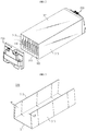
- FIG. 1 is a perspective view showing a battery module according to an embodiment of the present disclosure
- FIG. 2 is a perspective view showing that a sensing assembly is separated from the battery module of FIG. 1 .
- a battery module 10 may include a cell stack 100, a sensing assembly 200, and a module housing 300.
- the cell stack 100 may be an aggregate of secondary batteries, which includes pouch-type battery cells 110 stacked so that their large surfaces face each other.
- the cell stack 100 of the present disclosure may be an aggregate of secondary batteries accommodated in the module housing 300 so that the pouch-type battery cells 110 are provided to stand side by side and stacked in a horizontal direction.
- the pouch-type battery cells 110 means a secondary battery, which includes a pouch exterior, an electrode assembly provided to be accommodated in the pouch exterior, and an electrolyte.
- the pouch-type exterior may include two pouches, at least one of which may have a concave inner space.
- the electrode assembly may be accommodated in the inner space of the pouch. Peripheries of two pouches are fused together so that the inner space accommodating the electrode assembly may be sealed.
- An electrode lead 111 may be attached to the electrode assembly, and the electrode lead 111 may be interposed between the fused portions of the pouch exterior and exposed out of the pouch exterior to function as an electrode terminal of the battery cell 110.
- the sensing assembly 200 may include a plurality of bus bars, a printed circuit board to which one ends of the bus bars are connected, and a housing of the sensing assembly 200 giving a place for integrally fixing the bus bars and the printed circuit board and formed to cover the opening of the module housing 300.
- the bus bars are made of electrically conductive metals such as copper or aluminum to serve as a current path and may be connected in series and/or in parallel to the electrode leads 111 of the battery cells 110. One ends of the plurality of bus bars may be connected to the printed circuit board. On the printed circuit board, components such as a circuit chip for measuring the voltage of the individual battery cell 110 and a connector for transmitting or receiving signals to/from an external device may be provided.
- the sensing assembly 200 may be connected to a battery management system (BMS) to provide voltage information of the battery cell 110 to the BMS.
- BMS battery management system
- the BMS may control the operation of the battery cells 110 such as charging or discharging based on the voltage information.
- the module housing 300 has an inner space capable of accommodating the battery cells 110 therein and plays a role of giving a mechanical support for the accommodated battery cells 110 and protecting the battery cells 110 from external impacts.
- the module housing 300 may be made of a metal material to secure rigidity.
- the module housing 300 of the present disclosure is not limited to a metal housing.
- the module housing 300 may be made of any material such as a non-metallic material as long as it has a predetermined elasticity.
- the first module housing 310 may compress the cell stack 100, so the amount of swelling of the battery cells 110 during charging and discharging may be lowered without using a compression component such as a conventional strap.
- a compression pad conventionally interposed between the battery cells 110 may be not used, and thus the energy density of the battery module 10 may be improved. If required, it is also possible to add the conventional strap and the compression pad to the module housing 300 of the present disclosure to further increase the compression force to the battery cells 110.
- the first module housing 310 of this embodiment will be described in detail with reference to FIG. 3 .
- the first module housing 310 may include a lower plate 311, a first left pressing plate 312 and a first right pressing plate 313.
- the lower plate 311, the first left pressing plate 312 and the first right pressing plate 313 of the first module housing 310 are conceptually distinguished, and these plates may be also formed integrally.
- the lower plate 311 has a rectangular plate form with a predetermined area and serves to support the cell stack 100 at a lower portion of the cell stack 100.
- the predetermined area may be an area (L ⁇ T) corresponding to the product of a length (L) of the battery cell 110 and a thickness (T) of all the battery cells 110 of the cell stack 100.
- the first left pressing plate 312 and the first right pressing plate 313 form walls of the module housing 300 and may be provided corresponding to both side surfaces of the cell stack 100.
- the first left pressing plate 312 and the first right pressing plate 313 may extend upwards at the both side edge regions of the lower plate 311, which are provided side by side.
- both side edge regions correspond to long sides of the lower plate 311 and may almost coincide with the length of the battery cell 110.
- the first module housing 310 may be made of a metal with elasticity, and the first left pressing plate 312 and the first right pressing plate 313 may be formed to be narrowed at a predetermined angle ( ⁇ ) toward the inside of the lower plate 311.
- first left pressing plate 312 and the first right pressing plate 313 may extend upwards at both side edge regions of the lower plate 311 to form an acute angle ( ⁇ ) with respect to a vertically upper direction so that a gap between the first left pressing plate 312 and the first right pressing plate 313 becomes narrowed upwards.
- the first module housing 310 has elasticity, if the first left pressing plate 312 and the first right pressing plate 313 are pulled and then released, the first left pressing plate 312 and the first right pressing plate 313 may be restored to their original state. At this time, the elastic restoring forces of the first left pressing plate 312 and the first right pressing plate 313 act as a force for compressing both side surfaces of the cell stack 100.
- the upper plate 321 has a rectangular plate form to cover an upper portion of the cell stack 100 and may have an area corresponding to the lower plate 311.
- the upper plate 321 may be coupled to upper ends of the first left pressing plate 312 and the first right pressing plate 313 by welding or bolting.
- the module housing 300 of this embodiment may be provided in a rectangular tube form as the first module housing 310 and the upper plate 321 are coupled.
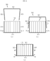
- FIGS. 4 and 5 are diagrams for illustrating each step of manufacturing a battery module 10 according to an embodiment of the present disclosure
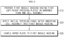
- FIG. 6 is a flowchart for illustrating a method of manufacturing a battery module 10 according to an embodiment of the present disclosure.
- the method of manufacturing the battery module 10 may include providing a first module housing 310, an upper plate 321, and a cell stack 100 to be accommodated in the first module housing 310 (S10), and inserting the cell stack 100 into the first module housing 310 and then pressing the cell stack 100 (S20).
- a first metal housing 310 is formed by shaping a metal plate with elasticity.
- the first module housing 310 is configured so that the first left pressing plate 312 and the first right pressing plate 313 are slightly narrowed toward the inside of the lower plate 311.
- the cell stack 100 is prepared by stacking as many pouch-type battery cells 110 as can be accommodated in the first module housing 310.
- the lower plate 311 of the first module housing 310 has a width corresponding to the thickness of all the battery cells 110 of the cell stack 100.
- the cell stack 100 is prepared by stacking a predetermined number of pouch-type battery cells 110 in a lateral direction in a standing state, and the lower plate 311 is provided such that its width is substantially equal to the total thickness of the predetermined number of pouch-type battery cells 110.
- the cell stack 100 of this embodiment is configured by stacking eight pouch-type battery cells 110 in total in the lateral direction, and the width of the lower plate 311 of the first module housing 310 is designed to have a size corresponding to the total thickness of eight pouch-type battery cells 110.
- the first left pressing plate 312 and the first right pressing plate 313 are pulled to broaden the gap therebetween so as to make a space into which the cell stack 100 may be inserted, and then the cell stack 100 is inserted into the inner space of the first module housing 310.
- the first left pressing plate 312 and the first right pressing plate 313 are released, as shown in the portion (a) of FIG. 5 , the first left pressing plate 312 and the first right pressing plate 313 are narrowed to compress both side surfaces of the cell stack 100.
- the battery cells 110 are constrained in the inner space of the first module housing 310 in an initially pressurized state, it is possible to securely fix the battery cells 110 and to suppress the thickness expansion caused by swelling during charging and discharging.
- the upper plate 321 is attached to the upper ends of the first left pressing plate 312 and the first right pressing plate 313 by welding (S30).
- welding For example, FIG. as shown in the portion (b) of FIG. 5 , both side edge regions of the upper plate 321 are placed on the upper ends of the first left pressing plate 312 and the first right pressing plate 313, and then welding (W) may be performed to their contact portions to cover the upper portion of the cell stack 100.
- the upper plate 321 may cover the upper portion of the cell stack 100 and also hold the first left pressing plate 312 and the first right pressing plate 313 so that the gap between the first left pressing plate 312 and the first right pressing plate 313 may be consistently maintained in a state where an initial pressing force is applied to the cell stack 100.
- the module housing 300 of this embodiment prepared as above may be finally provided in a tubular form.
- the electrode leads 111 of the battery cells 110 may be exposed to the outside through an open front surface and an open rear surface of the module housing 300, and bus bars may be electrically connected to the electrode leads 111 111 by, for example, ultrasonic welding.
- the housing of the sensing assembly 200 is mounted to the front surface and the rear surface of the module housing 300 to completely package the cell stack 100.
- FIGS 7 and 8 are diagrams for illustrating each step of manufacturing a battery module 10 according to another embodiment of the present disclosure.
- the battery module 10 further includes a second module housing 320 as compared to the former embodiment, which may further reinforce the initial pressing force to the cell stack 100 and improve the convenience in assembling.
- the second module housing 320 may be configured to compress the first left pressing plate 312 and the first right pressing plate 313 so that the first module housing 310 is covered.
- the second module housing 320 may include an upper plate 321, a second left pressing plate 322 and a second right pressing plate 323.
- the upper plate 321, the second left pressing plate 322 and the second right pressing plate 323 of the second module housing 320 are conceptually distinguished, and these three plates may also be integrally formed using an elastic metal material, similar to the first module housing 310.
- the upper plate 321 has a rectangular plate form and may be provided to cover an upper portion of the cell stack 100 at the upper portion of the cell stack 100.
- the second left pressing plate 322 and the second right pressing plate 323 may be provided to be narrowed at a predetermined angle toward the inside of the upper plate 321.
- the second left pressing plate 322 and the second right pressing plate 323 may extend downwards at the both side edge regions of the upper plate 321, which are provided side by side, to form an acute angle with respect to a vertically lower direction, respectively.
- the second left pressing plate 322 and the second right pressing plate 323 of the second module housing 320 are pulled within an elastic limit and then released, the second left pressing plate 322 and the second right pressing plate 323 may be restored to their original narrowed state, similar to the first left pressing plate 312 and the first right pressing plate 313 of the first module housing 310 described above.
- the second left pressing plate 322 and the second right pressing plate 323 of the second module housing 320 are pulled to cover the first module housing 310 and then released, the second left pressing plate 322 may be elastically biased toward the first left pressing plate 312 to be closely adhered thereto, and the second right pressing plate 323 may be elastically biased toward the first right pressing plate 313 to be closely adhered thereto.
- the method of manufacturing the battery module 10 including the second module housing 320 is identical to the method of the former embodiment till the step of pressing the cell stack 100 to the first module housing 310, as shown in FIG. 7 .
- the second left pressing plate 322 and the second right pressing plate 323 are pulled within an elastic limit to broaden the gap therebetween so that the upper plate 321 comes into contact with the upper ends of the first left pressing plate 312 and the first right pressing plate 313, and then the second left pressing plate 322 and the second right pressing plate 323 are released to press the first left pressing plate 312 and the first right pressing plate 313, different from the former embodiment.
- the compression force applied to the cell stack 100 may be doubled by adding the compression force of the first left and right pressing plates to the compression force of the second left and right pressing plates.
- the force for compressing the expansion of the battery cells 110 may be further strengthened as compared to the former embodiment.
- the first left pressing plate 312 and the first right pressing plate 313 may extend upwards at inner locations than terminal ends of the lower plate 311 by a predetermined distance so that the second left pressing plate 322 and the second right pressing plate 323 are located inner than the terminal ends of the lower plate 311. Accordingly, both side terminal ends of the lower plate 311 are exposed to the outside based on the first left pressing plate 312 and the first right pressing plate 313.
- both side terminal ends of the lower plate 311 will be referred to as welding spots 311a.
- the lower ends of the second left pressing plate 322 and the second right pressing plate 323 may be welded (W) to the welding spots 311a of the lower plate 311.
- the position of the upper plate 321 may be changed even by a slight impact during the welding process, and thus a jig is separately used to hold the position of the upper plate 321.
- the second module housing 320 strongly compresses the first module housing 310, the lower ends of the second left and right pressing plates do not move relative to the welding spots 311a, and thus the welding process may be performed more easily.
- the second left and right pressing plates may also be coupled to the first left and right pressing plates 312, 313 or the lower plate 311 of the first module housing 310 by bolting.
- the module housing 300 of this embodiment is configured so that the first module housing 310 is surrounded and compressed by the second module housing 320, it is also possible to omit the welding or bolting.
- the battery cells 110 may be accommodated in the module housing 300 in an initial pressurized state without using a separate component, and thus it is possible to suppress the volume expansion of the battery cells 110 during charging and discharging.
- places required for welding or fastening in assembling the module housing 300 may be minimized, it is possible to simplify the assembling process.
- the battery module may further include various devices (not shown) for controlling charge and discharge of the battery cells, such as a battery management system (BMS), a current sensor, a fuse, and the like.
- BMS battery management system
- the battery module may also be used as an energy source for electric vehicles, hybrid electric vehicles or power storage systems.
Landscapes
- Chemical & Material Sciences (AREA)
- Chemical Kinetics & Catalysis (AREA)
- Electrochemistry (AREA)
- General Chemical & Material Sciences (AREA)
- Inorganic Chemistry (AREA)
- Engineering & Computer Science (AREA)
- Manufacturing & Machinery (AREA)
- Battery Mounting, Suspending (AREA)
- Secondary Cells (AREA)
Abstract
Description
- The present disclosure relates to a battery module and a method of manufacturing the battery module, and more particularly, to a battery module having a module housing capable of compressing a cell assembly and a method of manufacturing the battery module.
- The present application claims priority to Korean Patent Application No.
10-2017-0162861 filed on November 30, 2017 - Secondary batteries widely used at the preset include lithium ion batteries, lithium polymer batteries, nickel cadmium batteries, nickel hydrogen batteries, nickel zinc batteries and the like. An operating voltage of such a unit secondary battery cell is about 2.5V to 4.2V. Therefore, if a higher output voltage is required, a plurality of battery cells may be connected in series. Alternatively, depending on the charge/discharge capacity, a plurality of battery cells may be connected in series and in parallel to configure a battery module.
- When a plurality of secondary battery cells are connected in series and/or in parallel to constitute a middle-sized or large-sized battery module, lithium-polymer pouch-type secondary battery cells having a high energy density and allowing easy stacking are frequently used, and the lithium-polymer pouch-type secondary battery cells are stacked to configure a cell assembly. After that, the cell assembly is packaged using a module housing for protection, and electric components for electrically connecting the secondary battery cells and measuring voltages thereof are added to configure a battery module.
- However, in the lithium-polymer pouch-type secondary battery, an electrode assembly is generally included in an aluminum laminate sheet, and thus the energy density is high in spite of a small size and weight, but the mechanical stiffness is weak. In particular, in the lithium-polymer pouch-type secondary batteries, the electrode may become thicker during repetitive charging/discharging processes, or gas may be generated due to decomposition of an internal electrolyte caused by side reactions. At this time, the pouch-type secondary battery cell may be swelled due to electrode expansion and/or gas generation, generated gas, which is called a 'swelling phenomenon'. For reference, the swelling phenomenon is more seriously influenced by the factor subordinate to the electrode expansion in charging and discharging.
- If the swelling phenomenon of the pouch-type secondary battery cell becomes intensified, the performance of the secondary battery cell may deteriorate, and the outer shape of the module housing may be changed, which may give an adverse effect to the structural stability of the battery module.
- According to the studies until now, it is known that the thickness expansion due to swelling is relatively small when the stacked secondary battery cells are strongly compressed from the early assembling state. Among the swelling phenomenon prevention technologies, there is known a technique of dispersing an expansion force by inserting a compression pad between secondary battery cells and, for example, a compressing technique by tightening a battery module with straps as disclosed in
JP Unexamined Patent Publication No. 2013-089566 - However, if the compression pad is used, the space for accommodating secondary battery cells is reduced as much as the volume of the compression pad, which is disadvantageous in terms of energy density per unit volume of the battery module. Also, if the strap is used, the pressure is irregularly applied to a region tightened by the strop and a region not tightened, and a strap assembling process is further required and the number of components increase. Thus, it is demanded to develop a battery module having an assembling structure capable of solving these problems.
- The present disclosure is designed to solve the problems of the related art, and therefore the present disclosure is directed to providing a battery module, which may accommodate battery cells in a pressurized state without using a separate component, and a method of manufacturing the battery module.
- These and other objects and advantages of the present disclosure may be understood from the following detailed description and will become more fully apparent from the exemplary embodiments of the present disclosure. Also, it will be easily understood that the objects and advantages of the present disclosure may be realized by the means shown in the appended claims and combinations thereof.
- In one aspect of the present disclosure, there is provided a battery module, which includes a cell stack having pouch-type battery cells provided to stand side by side and stacked in a horizontal direction, and a module housing configured to accommodate the cell stack,
wherein the module housing includes: a lower plate provided in a rectangular plate form to support the cell stack at a lower portion of the cell stack; and a first left pressing plate and a first right pressing plate having elasticity and extending upwards at both side edge regions of the lower plate, which are provided side by side, to form an acute angle with respect to a vertically upper direction so that a gap between the first left pressing plate and the first right pressing plate becomes narrowed upwards, wherein the first left pressing plate and the first right pressing plate are elastically biased to press both side surfaces of the cell stack. - The module housing may further include an upper plate coupled to upper ends of the first left pressing plate and the first right pressing plate by welding or bolting to cover an upper portion of the cell stack.
- The module housing may further include an upper plate provided in a rectangular plate form to cover an upper portion of the cell stack at the upper portion of the cell stack; a second left pressing plate and a second right pressing plate having elasticity and extending downwards respectively at both side edge regions of the upper plate so that the second left pressing plate is elastically biased to be closely adhered to an outer surface of the first left pressing plate and the second right pressing plate is elastically biased to be closely adhered to an outer surface of the first right pressing plate.
- The first left pressing plate and the first right pressing plate may be formed to extend upwards at inner locations than terminal ends of the lower plate by a predetermined distance so that the second left pressing plate and the second right pressing plate are located inner than the terminal ends of the lower plate.
- Lower ends of the second left pressing plate and the second right pressing plate may be welded to an upper surface of the lower plate.
- In another aspect of the present disclosure, there is also provided a method of manufacturing a battery module, comprising: preparing a first module housing, which includes a lower plate having a rectangular plate form and a first left pressing plate and a first right pressing plate having elasticity and extending upwards at both side edge regions of the lower plate, which are provided side by side, to form an acute angle with respect to a vertical direction so that a gap between the first left pressing plate and the first right pressing plate becomes narrowed upwards, and a cell stack that is to be accommodated in the first module housing; and pulling the first left pressing plate and the first right pressing plate within an elastic limit to broaden the gap therebetween, then inserting the cell stack into the first module housing, and releasing the first left pressing plate and first right pressing plate to press both side surfaces of the cell stack.
- The method may further comprise coupling an upper plate to upper ends of the first left pressing plate and first right pressing plate by welding or bolting.
- Also, in another aspect of the present disclosure, the method may further comprise preparing a second module housing, which includes an upper plate having a rectangular plate form and a second left pressing plate and a second right pressing plate having elasticity and extending downwards respectively at both side edge regions of the upper plate, which are provided side by side, to form an acute angle with respect to a vertically lower direction so that a gap between the second left pressing plate and the second right pressing plate becomes narrowed downwards; and pulling the second left pressing plate and second right pressing plate within an elastic limit to place the upper plate on upper ends of the first left pressing plate and the first right pressing plate, and then releasing the second left pressing plate and the second right pressing plate to press the first left pressing plate and the first right pressing plate.
- The method may further comprise coupling lower ends of the second left pressing plate and the second right pressing plate to the first module housing by welding or bolting.
- According to an embodiment of the present disclosure, battery cells may be accommodated in a module housing in a pressurized state without using any separate component. Since the battery cells are accommodated in the module housing in a strongly pressurized state at an initial stage, it is possible to suppress the volume expansion during charging and discharging.
- According to another embodiment of the present disclosure, since a separate component is not needed to press the battery cells, it is possible to reduce the manufacturing cost.
- According to still another embodiment of the present disclosure, since the number of places where welding or fastening is required in assembling the module housing is minimized, it is possible to simplify the assembly process.
-
-
FIG. 1 is a perspective view showing a battery module according to an embodiment of the present disclosure. -
FIG. 2 is a perspective view showing that a sensing assembly is separated from the battery module ofFIG. 1 . -
FIG. 3 is a perspective view showing a first module housing according to an embodiment of the present disclosure. -
FIGS. 4 and5 are diagrams for illustrating each step of manufacturing a battery module according to an embodiment of the present disclosure. -
FIG. 6 is a flowchart for illustrating a method of manufacturing a battery module according to an embodiment of the present disclosure. -
FIGS 7 and8 are diagrams for illustrating each step of manufacturing a battery module according to another embodiment of the present disclosure. - The embodiments disclosed herein are provided for more perfect explanation of the present disclosure, and thus the shape, size and the like of components may be exaggerated, omitted or simplified in the drawings for better understanding. Thus, the size and ratio of components in the drawings do not wholly reflect the actual size and ratio.
- Hereinafter, preferred embodiments of the present disclosure will be described in detail with reference to the accompanying drawings. Prior to the description, it should be understood that the terms used in the specification and the appended claims should not be construed as limited to general and dictionary meanings, but interpreted based on the meanings and concepts corresponding to technical aspects of the present disclosure on the basis of the principle that the inventor is allowed to define terms appropriately for the best explanation.
- Therefore, the description proposed herein is just a preferable example for the purpose of illustrations only, not intended to limit the scope of the disclosure, so it should be understood that other equivalents and modifications could be made thereto without departing from the scope of the disclosure.
-
FIG. 1 is a perspective view showing a battery module according to an embodiment of the present disclosure, andFIG. 2 is a perspective view showing that a sensing assembly is separated from the battery module ofFIG. 1 . - Referring to
FIGS. 1 and2 , abattery module 10 according to an embodiment of the present disclosure may include acell stack 100, asensing assembly 200, and amodule housing 300. - The
cell stack 100 may be an aggregate of secondary batteries, which includes pouch-type battery cells 110 stacked so that their large surfaces face each other. In more detail, thecell stack 100 of the present disclosure may be an aggregate of secondary batteries accommodated in themodule housing 300 so that the pouch-type battery cells 110 are provided to stand side by side and stacked in a horizontal direction. - Here, the pouch-
type battery cells 110 means a secondary battery, which includes a pouch exterior, an electrode assembly provided to be accommodated in the pouch exterior, and an electrolyte. For example, the pouch-type exterior may include two pouches, at least one of which may have a concave inner space. In addition, the electrode assembly may be accommodated in the inner space of the pouch. Peripheries of two pouches are fused together so that the inner space accommodating the electrode assembly may be sealed. - An
electrode lead 111 may be attached to the electrode assembly, and theelectrode lead 111 may be interposed between the fused portions of the pouch exterior and exposed out of the pouch exterior to function as an electrode terminal of thebattery cell 110. - Though not shown in the figures for convenience, the
sensing assembly 200 may include a plurality of bus bars, a printed circuit board to which one ends of the bus bars are connected, and a housing of thesensing assembly 200 giving a place for integrally fixing the bus bars and the printed circuit board and formed to cover the opening of themodule housing 300. - The bus bars are made of electrically conductive metals such as copper or aluminum to serve as a current path and may be connected in series and/or in parallel to the electrode leads 111 of the
battery cells 110. One ends of the plurality of bus bars may be connected to the printed circuit board. On the printed circuit board, components such as a circuit chip for measuring the voltage of theindividual battery cell 110 and a connector for transmitting or receiving signals to/from an external device may be provided. - The
sensing assembly 200 may be connected to a battery management system (BMS) to provide voltage information of thebattery cell 110 to the BMS. The BMS may control the operation of thebattery cells 110 such as charging or discharging based on the voltage information. - The
module housing 300 has an inner space capable of accommodating thebattery cells 110 therein and plays a role of giving a mechanical support for the accommodatedbattery cells 110 and protecting thebattery cells 110 from external impacts. Thus, themodule housing 300 may be made of a metal material to secure rigidity. However, themodule housing 300 of the present disclosure is not limited to a metal housing. For example, themodule housing 300 may be made of any material such as a non-metallic material as long as it has a predetermined elasticity. - As shown in
FIG. 2 , themodule housing 300 according to an embodiment of the present disclosure may include afirst module housing 310 and anupper plate 321. - As will be explained in more detail later, in this embodiment, the
first module housing 310 may compress thecell stack 100, so the amount of swelling of thebattery cells 110 during charging and discharging may be lowered without using a compression component such as a conventional strap. In addition, a compression pad conventionally interposed between thebattery cells 110 may be not used, and thus the energy density of thebattery module 10 may be improved. If required, it is also possible to add the conventional strap and the compression pad to themodule housing 300 of the present disclosure to further increase the compression force to thebattery cells 110. - The
first module housing 310 of this embodiment will be described in detail with reference toFIG. 3 . Thefirst module housing 310 may include alower plate 311, a firstleft pressing plate 312 and a firstright pressing plate 313. However, thelower plate 311, the firstleft pressing plate 312 and the firstright pressing plate 313 of thefirst module housing 310 are conceptually distinguished, and these plates may be also formed integrally. - The
lower plate 311 has a rectangular plate form with a predetermined area and serves to support thecell stack 100 at a lower portion of thecell stack 100. Here, the predetermined area may be an area (L×T) corresponding to the product of a length (L) of thebattery cell 110 and a thickness (T) of all thebattery cells 110 of thecell stack 100. - The first
left pressing plate 312 and the firstright pressing plate 313 form walls of themodule housing 300 and may be provided corresponding to both side surfaces of thecell stack 100. - The first
left pressing plate 312 and the firstright pressing plate 313 may extend upwards at the both side edge regions of thelower plate 311, which are provided side by side. Here, both side edge regions correspond to long sides of thelower plate 311 and may almost coincide with the length of thebattery cell 110. - In particular, the
first module housing 310 according to the present disclosure may be made of a metal with elasticity, and the firstleft pressing plate 312 and the firstright pressing plate 313 may be formed to be narrowed at a predetermined angle (θ) toward the inside of thelower plate 311. - In other words, the first
left pressing plate 312 and the firstright pressing plate 313 may extend upwards at both side edge regions of thelower plate 311 to form an acute angle (θ) with respect to a vertically upper direction so that a gap between the firstleft pressing plate 312 and the firstright pressing plate 313 becomes narrowed upwards. - Since the
first module housing 310 has elasticity, if the firstleft pressing plate 312 and the firstright pressing plate 313 are pulled and then released, the firstleft pressing plate 312 and the firstright pressing plate 313 may be restored to their original state. At this time, the elastic restoring forces of the firstleft pressing plate 312 and the firstright pressing plate 313 act as a force for compressing both side surfaces of thecell stack 100. - The
upper plate 321 has a rectangular plate form to cover an upper portion of thecell stack 100 and may have an area corresponding to thelower plate 311. Theupper plate 321 may be coupled to upper ends of the firstleft pressing plate 312 and the firstright pressing plate 313 by welding or bolting. - Thus, the
module housing 300 of this embodiment may be provided in a rectangular tube form as thefirst module housing 310 and theupper plate 321 are coupled. - Hereinafter, a method of manufacturing the
battery module 10 according to the present disclosure using themodule housing 300 configured as above will be described in more detail. -
FIGS. 4 and5 are diagrams for illustrating each step of manufacturing abattery module 10 according to an embodiment of the present disclosure, andFIG. 6 is a flowchart for illustrating a method of manufacturing abattery module 10 according to an embodiment of the present disclosure. - The method of manufacturing the
battery module 10 according to the present disclosure may include providing afirst module housing 310, anupper plate 321, and acell stack 100 to be accommodated in the first module housing 310 (S10), and inserting thecell stack 100 into thefirst module housing 310 and then pressing the cell stack 100 (S20). - First, a
first metal housing 310 is formed by shaping a metal plate with elasticity. At this time, as described above, thefirst module housing 310 is configured so that the firstleft pressing plate 312 and the firstright pressing plate 313 are slightly narrowed toward the inside of thelower plate 311. In addition, thecell stack 100 is prepared by stacking as many pouch-type battery cells 110 as can be accommodated in thefirst module housing 310. - The
lower plate 311 of thefirst module housing 310 has a width corresponding to the thickness of all thebattery cells 110 of thecell stack 100. In other words, thecell stack 100 is prepared by stacking a predetermined number of pouch-type battery cells 110 in a lateral direction in a standing state, and thelower plate 311 is provided such that its width is substantially equal to the total thickness of the predetermined number of pouch-type battery cells 110. - For example, the
cell stack 100 of this embodiment is configured by stacking eight pouch-type battery cells 110 in total in the lateral direction, and the width of thelower plate 311 of thefirst module housing 310 is designed to have a size corresponding to the total thickness of eight pouch-type battery cells 110. - After that, as shown in
FIG. 4 , the firstleft pressing plate 312 and the firstright pressing plate 313 are pulled to broaden the gap therebetween so as to make a space into which thecell stack 100 may be inserted, and then thecell stack 100 is inserted into the inner space of thefirst module housing 310. - After that, if the first
left pressing plate 312 and the firstright pressing plate 313 are released, as shown in the portion (a) ofFIG. 5 , the firstleft pressing plate 312 and the firstright pressing plate 313 are narrowed to compress both side surfaces of thecell stack 100. - Since the
battery cells 110 are constrained in the inner space of thefirst module housing 310 in an initially pressurized state, it is possible to securely fix thebattery cells 110 and to suppress the thickness expansion caused by swelling during charging and discharging. - After that, the
upper plate 321 is attached to the upper ends of the firstleft pressing plate 312 and the firstright pressing plate 313 by welding (S30). For example, FIG. as shown in the portion (b) ofFIG. 5 , both side edge regions of theupper plate 321 are placed on the upper ends of the firstleft pressing plate 312 and the firstright pressing plate 313, and then welding (W) may be performed to their contact portions to cover the upper portion of thecell stack 100. - The
upper plate 321 may cover the upper portion of thecell stack 100 and also hold the firstleft pressing plate 312 and the firstright pressing plate 313 so that the gap between the firstleft pressing plate 312 and the firstright pressing plate 313 may be consistently maintained in a state where an initial pressing force is applied to thecell stack 100. - The
module housing 300 of this embodiment prepared as above may be finally provided in a tubular form. The electrode leads 111 of thebattery cells 110 may be exposed to the outside through an open front surface and an open rear surface of themodule housing 300, and bus bars may be electrically connected to the electrode leads 111 111 by, for example, ultrasonic welding. After that, the housing of thesensing assembly 200 is mounted to the front surface and the rear surface of themodule housing 300 to completely package thecell stack 100. - Subsequently, a
battery module 10 according to other embodiments of the present disclosure will be described. The same reference sign as in the former embodiment designates the same component. The same component will not described again, and features different from the former embodiment will be described in detail. -
FIGS 7 and8 are diagrams for illustrating each step of manufacturing abattery module 10 according to another embodiment of the present disclosure. - The
battery module 10 according to another embodiment of the present disclosure further includes asecond module housing 320 as compared to the former embodiment, which may further reinforce the initial pressing force to thecell stack 100 and improve the convenience in assembling. - The
second module housing 320 may be configured to compress the firstleft pressing plate 312 and the firstright pressing plate 313 so that thefirst module housing 310 is covered. Thesecond module housing 320 may include anupper plate 321, a secondleft pressing plate 322 and a secondright pressing plate 323. Theupper plate 321, the secondleft pressing plate 322 and the secondright pressing plate 323 of thesecond module housing 320 are conceptually distinguished, and these three plates may also be integrally formed using an elastic metal material, similar to thefirst module housing 310. - The
upper plate 321 has a rectangular plate form and may be provided to cover an upper portion of thecell stack 100 at the upper portion of thecell stack 100. The secondleft pressing plate 322 and the secondright pressing plate 323 may be provided to be narrowed at a predetermined angle toward the inside of theupper plate 321. - That is, the second
left pressing plate 322 and the secondright pressing plate 323 may extend downwards at the both side edge regions of theupper plate 321, which are provided side by side, to form an acute angle with respect to a vertically lower direction, respectively. - If the second
left pressing plate 322 and the secondright pressing plate 323 of thesecond module housing 320 are pulled within an elastic limit and then released, the secondleft pressing plate 322 and the secondright pressing plate 323 may be restored to their original narrowed state, similar to the firstleft pressing plate 312 and the firstright pressing plate 313 of thefirst module housing 310 described above. - Thus, as shown in
FIG. 8 , if the secondleft pressing plate 322 and the secondright pressing plate 323 of thesecond module housing 320 are pulled to cover thefirst module housing 310 and then released, the secondleft pressing plate 322 may be elastically biased toward the firstleft pressing plate 312 to be closely adhered thereto, and the secondright pressing plate 323 may be elastically biased toward the firstright pressing plate 313 to be closely adhered thereto. - The method of manufacturing the
battery module 10 including thesecond module housing 320 is identical to the method of the former embodiment till the step of pressing thecell stack 100 to thefirst module housing 310, as shown inFIG. 7 . After that, the secondleft pressing plate 322 and the secondright pressing plate 323 are pulled within an elastic limit to broaden the gap therebetween so that theupper plate 321 comes into contact with the upper ends of the firstleft pressing plate 312 and the firstright pressing plate 313, and then the secondleft pressing plate 322 and the secondright pressing plate 323 are released to press the firstleft pressing plate 312 and the firstright pressing plate 313, different from the former embodiment. - In this case, the compression force applied to the
cell stack 100 may be doubled by adding the compression force of the first left and right pressing plates to the compression force of the second left and right pressing plates. As a result, the force for compressing the expansion of thebattery cells 110 may be further strengthened as compared to the former embodiment. - Also, in this embodiment, the first
left pressing plate 312 and the firstright pressing plate 313 may extend upwards at inner locations than terminal ends of thelower plate 311 by a predetermined distance so that the secondleft pressing plate 322 and the secondright pressing plate 323 are located inner than the terminal ends of thelower plate 311. Accordingly, both side terminal ends of thelower plate 311 are exposed to the outside based on the firstleft pressing plate 312 and the firstright pressing plate 313. Hereinafter, both side terminal ends of thelower plate 311 will be referred to aswelding spots 311a. - After the
second module housing 320 is provided to cover thefirst module housing 310 as described above, as shown in the portion (c) ofFIG. 8 , the lower ends of the secondleft pressing plate 322 and the secondright pressing plate 323 may be welded (W) to thewelding spots 311a of thelower plate 311. - In the former embodiment, when the
upper plate 321 is placed on the upper ends of the firstleft pressing plate 312 and the firstright pressing plate 313 and the welding is performed, the position of theupper plate 321 may be changed even by a slight impact during the welding process, and thus a jig is separately used to hold the position of theupper plate 321. - Meanwhile, in this embodiment, since the
second module housing 320 strongly compresses thefirst module housing 310, the lower ends of the second left and right pressing plates do not move relative to thewelding spots 311a, and thus the welding process may be performed more easily. - The second left and right pressing plates may also be coupled to the first left and right
pressing plates lower plate 311 of thefirst module housing 310 by bolting. For reference, since themodule housing 300 of this embodiment is configured so that thefirst module housing 310 is surrounded and compressed by thesecond module housing 320, it is also possible to omit the welding or bolting. - If the
battery module 10 having the configuration and action according to the present disclosure and its manufacturing method are used, thebattery cells 110 may be accommodated in themodule housing 300 in an initial pressurized state without using a separate component, and thus it is possible to suppress the volume expansion of thebattery cells 110 during charging and discharging. In addition, since places required for welding or fastening in assembling themodule housing 300 may be minimized, it is possible to simplify the assembling process. - Meanwhile, the battery module may further include various devices (not shown) for controlling charge and discharge of the battery cells, such as a battery management system (BMS), a current sensor, a fuse, and the like. The battery module may also be used as an energy source for electric vehicles, hybrid electric vehicles or power storage systems.
- The present disclosure has been described in detail. However, it should be understood that the detailed description and specific examples, while indicating preferred embodiments of the disclosure, are given by way of illustration only, since various changes and modifications within the scope of the disclosure will become apparent to those skilled in the art from this detailed description.
- Meanwhile, when the terms indicating up, down, left and right directions are used in the specification, it is obvious to those skilled in the art that these merely represent relative locations for convenience in explanation and may vary based on a location of an observer or an object to be observed.
Claims (9)
- A battery module, which includes a cell stack having pouch-type battery cells provided to stand side by side and stacked in a horizontal direction, and a module housing configured to accommodate the cell stack,
wherein the module housing includes:a lower plate provided in a rectangular plate form to support the cell stack at a lower portion of the cell stack; anda first left pressing plate and a first right pressing plate having elasticity and extending upwards at both side edge regions of the lower plate, which are provided side by side, to form an acute angle with respect to a vertically upper direction so that a gap between the first left pressing plate and the first right pressing plate becomes narrowed upwards,wherein the first left pressing plate and the first right pressing plate are elastically biased to press both side surfaces of the cell stack. - The battery module according to claim 1,
wherein the module housing further includes an upper plate coupled to upper ends of the first left pressing plate and the first right pressing plate by welding or bolting to cover an upper portion of the cell stack. - The battery module according to claim 1,
wherein the module housing further includes:an upper plate provided in a rectangular plate form to cover an upper portion of the cell stack at the upper portion of the cell stack;a second left pressing plate and a second right pressing plate having elasticity and extending downwards respectively at both side edge regions of the upper plate so that the second left pressing plate is elastically biased to be closely adhered to an outer surface of the first left pressing plate and the second right pressing plate is elastically biased to be closely adhered to an outer surface of the first right pressing plate. - The battery module according to claim 3,
wherein the first left pressing plate and the first right pressing plate are formed to extend upwards at inner locations than terminal ends of the lower plate by a predetermined distance so that the second left pressing plate and the second right pressing plate are located inner than the terminal ends of the lower plate. - The battery module according to claim 4,
wherein lower ends of the second left pressing plate and the second right pressing plate are welded to an upper surface of the lower plate. - A method of manufacturing a battery module, comprising:preparing a first module housing, which includes a lower plate having a rectangular plate form and a first left pressing plate and a first right pressing plate having elasticity and extending upwards at both side edge regions of the lower plate, which are provided side by side, to form an acute angle with respect to a vertical direction so that a gap between the first left pressing plate and the first right pressing plate becomes narrowed upwards, and a cell stack that is to be accommodated in the first module housing; andpulling the first left pressing plate and the first right pressing plate within an elastic limit to broaden the gap therebetween, then inserting the cell stack into the first module housing, and releasing the first left pressing plate and first right pressing plate to press both side surfaces of the cell stack.
- The method of manufacturing a battery module according to claim 6, further comprising:
coupling an upper plate to upper ends of the first left pressing plate and first right pressing plate by welding or bolting. - The method of manufacturing a battery module according to claim 6, further comprising:preparing a second module housing, which includes an upper plate having a rectangular plate form and a second left pressing plate and a second right pressing plate having elasticity and extending downwards respectively at both side edge regions of the upper plate, which are provided side by side, to form an acute angle with respect to a vertically lower direction so that a gap between the second left pressing plate and the second right pressing plate becomes narrowed downwards; andpulling the second left pressing plate and second right pressing plate within an elastic limit to place the upper plate on upper ends of the first left pressing plate and the first right pressing plate, and then releasing the second left pressing plate and the second right pressing plate to press the first left pressing plate and the first right pressing plate.
- The method of manufacturing a battery module according to claim 8, further comprising:
coupling lower ends of the second left pressing plate and the second right pressing plate to the first module housing by welding or bolting.
Applications Claiming Priority (2)
| Application Number | Priority Date | Filing Date | Title |
|---|---|---|---|
| KR1020170162861A KR102267606B1 (en) | 2017-11-30 | 2017-11-30 | Battery module an initial pressing force reinforcing structure for a battery cell assembly and Method for manufacturing the same |
| PCT/KR2018/011899 WO2019107734A1 (en) | 2017-11-30 | 2018-10-10 | Battery module having initial pressing force strengthening structure for cell assembly, and method for manufacturing same |
Publications (3)
| Publication Number | Publication Date |
|---|---|
| EP3629396A1 true EP3629396A1 (en) | 2020-04-01 |
| EP3629396A4 EP3629396A4 (en) | 2020-07-29 |
| EP3629396B1 EP3629396B1 (en) | 2024-08-28 |
Family
ID=66665630
Family Applications (1)
| Application Number | Title | Priority Date | Filing Date |
|---|---|---|---|
| EP18882705.9A Active EP3629396B1 (en) | 2017-11-30 | 2018-10-10 | Method for manufacturing a battery module having initial pressing force strengthening structure for cell assembly |
Country Status (8)
| Country | Link |
|---|---|
| US (2) | US11380950B2 (en) |
| EP (1) | EP3629396B1 (en) |
| JP (1) | JP7045564B2 (en) |
| KR (1) | KR102267606B1 (en) |
| CN (1) | CN110998902B (en) |
| ES (1) | ES2988268T3 (en) |
| HU (1) | HUE068599T2 (en) |
| WO (1) | WO2019107734A1 (en) |
Cited By (1)
| Publication number | Priority date | Publication date | Assignee | Title |
|---|---|---|---|---|
| EP4401183A1 (en) * | 2023-01-10 | 2024-07-17 | Fagor Ederlan, S.Coop. | Battery module for an electric vehicle |
Families Citing this family (21)
| Publication number | Priority date | Publication date | Assignee | Title |
|---|---|---|---|---|
| JP1646780S (en) * | 2019-02-07 | 2019-12-02 | ||
| JP1646779S (en) * | 2019-02-07 | 2019-12-02 | ||
| JP1646781S (en) * | 2019-02-07 | 2019-12-02 | ||
| JP1646778S (en) * | 2019-02-07 | 2019-12-02 | ||
| JP7224249B2 (en) * | 2019-07-03 | 2023-02-17 | 大豊工業株式会社 | Battery cases and battery modules |
| CN113994534B (en) * | 2019-07-10 | 2024-04-02 | 本田技研工业株式会社 | Electric storage module and method of manufacturing electric storage module |
| JP6898972B2 (en) * | 2019-08-07 | 2021-07-07 | 本田技研工業株式会社 | Battery case manufacturing method and battery case |
| JP7427903B2 (en) * | 2019-10-08 | 2024-02-06 | 株式会社Gsユアサ | Power storage device |
| KR102480735B1 (en) | 2019-10-10 | 2022-12-22 | 주식회사 엘지에너지솔루션 | Battery module and battery pack including the same |
| KR102750892B1 (en) * | 2019-11-18 | 2025-01-06 | 주식회사 엘지에너지솔루션 | Apparatus and method of manufacturing battery module |
| KR102767701B1 (en) * | 2020-03-06 | 2025-02-12 | 주식회사 엘지에너지솔루션 | Battery module and manufacturing method thereof |
| KR102767702B1 (en) | 2020-03-06 | 2025-02-12 | 주식회사 엘지에너지솔루션 | Battery module and manufacturing method thereof |
| KR102754508B1 (en) * | 2020-03-17 | 2025-01-13 | 주식회사 엘지에너지솔루션 | Battery module and battery pack including the same |
| KR20210125674A (en) * | 2020-04-09 | 2021-10-19 | 에스케이이노베이션 주식회사 | Battery Modules Housing Welding Methods For Preventing Heat Damage and Battery Module Thereof |
| KR20220000637A (en) | 2020-06-26 | 2022-01-04 | 주식회사 엘지에너지솔루션 | Battery module and battery pack including the same |
| US12401080B2 (en) | 2020-11-05 | 2025-08-26 | Lg Energy Solution, Ltd. | Method of setting cell pressure range for secondary battery module |
| KR20220081028A (en) | 2020-12-08 | 2022-06-15 | 주식회사 엘지에너지솔루션 | Battery module and battery pack including the same |
| CN114552112B (en) * | 2022-01-14 | 2024-01-30 | 国网河北省电力有限公司保定供电分公司 | Real-time personnel state monitoring device |
| CN115763941A (en) * | 2022-12-08 | 2023-03-07 | 无锡奥特维智能装备有限公司 | Electricity core closing device |
| GB2629395A (en) * | 2023-04-27 | 2024-10-30 | Dyson Technology Ltd | A battery enclosure |
| GB2634195B (en) * | 2023-08-29 | 2026-02-18 | Dyson Technology Ltd | A battery enclosure |
Family Cites Families (23)
| Publication number | Priority date | Publication date | Assignee | Title |
|---|---|---|---|---|
| JPS5915396Y2 (en) * | 1978-08-31 | 1984-05-08 | 新神戸電機株式会社 | Storage battery mounting device |
| US6087036A (en) | 1997-07-25 | 2000-07-11 | 3M Innovative Properties Company | Thermal management system and method for a solid-state energy storing device |
| US9484591B2 (en) * | 2006-03-06 | 2016-11-01 | Lg Chem, Ltd. | Voltage sensing member and battery module employed with the same |
| KR100882914B1 (en) | 2007-05-21 | 2009-02-10 | 삼성에스디아이 주식회사 | Battery Pack |
| JP5256683B2 (en) | 2007-10-17 | 2013-08-07 | パナソニック株式会社 | Pressure structure of laminate |
| JP2009182001A (en) | 2008-01-29 | 2009-08-13 | Nisshin Steel Co Ltd | Cell stack structure |
| US20100122461A1 (en) | 2008-11-20 | 2010-05-20 | Constantinos Minas | Compact spring loaded fuel cell monopolar stack |
| US8999557B2 (en) | 2010-04-21 | 2015-04-07 | Samsung Sdi Co., Ltd. | Battery pack with elastic frame |
| US9343772B2 (en) | 2010-10-08 | 2016-05-17 | Samsung Sdi Co., Ltd. | Rechargeable battery |
| KR101191659B1 (en) * | 2010-11-05 | 2012-10-17 | 에스비리모티브 주식회사 | Battery module |
| KR101816813B1 (en) * | 2010-12-30 | 2018-01-11 | 에스케이이노베이션 주식회사 | Case of pouched type cell |
| TWI456817B (en) * | 2011-09-27 | 2014-10-11 | Au Optronics Corp | Battery device |
| JP5751127B2 (en) | 2011-10-21 | 2015-07-22 | 株式会社豊田自動織機 | Battery module |
| KR101505722B1 (en) | 2012-04-09 | 2015-03-25 | 주식회사 엘지화학 | Lithium secondary battery comprising elastic clip device and method for preparation the same |
| JP2014078498A (en) | 2012-09-19 | 2014-05-01 | Toshiba Corp | Battery module |
| KR20140098490A (en) * | 2013-01-31 | 2014-08-08 | 삼성에스디아이 주식회사 | Rechargeable battery |
| US20140295235A1 (en) | 2013-03-29 | 2014-10-02 | Samsung Sdi Co., Ltd. | Battery module |
| KR102211526B1 (en) | 2014-04-23 | 2021-02-02 | 삼성에스디아이 주식회사 | Rechargeable battery |
| JP2016143443A (en) | 2015-01-29 | 2016-08-08 | ブラザー工業株式会社 | Cell module |
| KR102005488B1 (en) * | 2015-06-16 | 2019-10-01 | 주식회사 엘지화학 | Cell Cover for secondary battery and battery module including the same |
| JP6258272B2 (en) * | 2015-08-11 | 2018-01-10 | 株式会社東芝 | Battery module |
| KR102065098B1 (en) * | 2016-08-12 | 2020-01-10 | 주식회사 엘지화학 | Secondary battery module improved in frame structure and frame assembly for the same |
| KR102178959B1 (en) | 2017-04-06 | 2020-11-13 | 주식회사 엘지화학 | End plate, battery module, battery pack comprising the battery module and vehicle comprising the battery pack |
-
2017
- 2017-11-30 KR KR1020170162861A patent/KR102267606B1/en active Active
-
2018
- 2018-10-10 US US16/611,728 patent/US11380950B2/en active Active
- 2018-10-10 EP EP18882705.9A patent/EP3629396B1/en active Active
- 2018-10-10 WO PCT/KR2018/011899 patent/WO2019107734A1/en not_active Ceased
- 2018-10-10 HU HUE18882705A patent/HUE068599T2/en unknown
- 2018-10-10 CN CN201880049774.XA patent/CN110998902B/en active Active
- 2018-10-10 JP JP2019561988A patent/JP7045564B2/en active Active
- 2018-10-10 ES ES18882705T patent/ES2988268T3/en active Active
-
2022
- 2022-06-09 US US17/836,556 patent/US11769925B2/en active Active
Cited By (1)
| Publication number | Priority date | Publication date | Assignee | Title |
|---|---|---|---|---|
| EP4401183A1 (en) * | 2023-01-10 | 2024-07-17 | Fagor Ederlan, S.Coop. | Battery module for an electric vehicle |
Also Published As
| Publication number | Publication date |
|---|---|
| US20200106058A1 (en) | 2020-04-02 |
| EP3629396B1 (en) | 2024-08-28 |
| WO2019107734A1 (en) | 2019-06-06 |
| US20220302529A1 (en) | 2022-09-22 |
| JP2020520060A (en) | 2020-07-02 |
| ES2988268T3 (en) | 2024-11-19 |
| KR102267606B1 (en) | 2021-06-21 |
| KR20190063809A (en) | 2019-06-10 |
| JP7045564B2 (en) | 2022-04-01 |
| US11380950B2 (en) | 2022-07-05 |
| CN110998902A (en) | 2020-04-10 |
| CN110998902B (en) | 2022-08-16 |
| EP3629396A4 (en) | 2020-07-29 |
| HUE068599T2 (en) | 2025-01-28 |
| US11769925B2 (en) | 2023-09-26 |
Similar Documents
| Publication | Publication Date | Title |
|---|---|---|
| US11769925B2 (en) | Battery module having initial pressing force reinforcing structure for cell assembly and method of manufacturing the same | |
| US12261326B2 (en) | Battery module, battery pack including same battery module, and automobile including same battery pack | |
| EP3836244B1 (en) | Battery module and battery pack comprising battery module | |
| US11764435B2 (en) | Battery module to which battery cell pressing-type end plate and expandable sensing housing structure are applied | |
| EP3282515B1 (en) | Battery module, battery pack comprising battery module, and vehicle comprising battery pack | |
| EP3644401B1 (en) | Battery module, and battery pack and vehicle comprising same | |
| EP3675239A1 (en) | Battery module, and battery pack and automobile comprising same | |
| CN113273026A (en) | Battery module and battery pack including the same | |
| US11205817B2 (en) | Battery pack | |
| KR101984314B1 (en) | Secondary battery | |
| KR20150142790A (en) | End plate for battery module assembly thereby preventing a change in the external shape of the battery module due to swelling, and battery pack having the same | |
| CN114175389A (en) | Battery pack, electronic device, and vehicle | |
| KR20150137840A (en) | Unit battery module and Battery module having the same | |
| US12456774B2 (en) | Battery pack, energy storage system, and vehicle | |
| KR20190060963A (en) | Secondary battery | |
| KR20160054268A (en) | Secondary battery cell and battery module including the same | |
| EP4459740A1 (en) | Battery module | |
| EP4675802A1 (en) | Battery module and battery pack and vehicle including same | |
| KR20190008654A (en) | Battery Pack |
Legal Events
| Date | Code | Title | Description |
|---|---|---|---|
| STAA | Information on the status of an ep patent application or granted ep patent |
Free format text: STATUS: THE INTERNATIONAL PUBLICATION HAS BEEN MADE |
|
| PUAI | Public reference made under article 153(3) epc to a published international application that has entered the european phase |
Free format text: ORIGINAL CODE: 0009012 |
|
| STAA | Information on the status of an ep patent application or granted ep patent |
Free format text: STATUS: REQUEST FOR EXAMINATION WAS MADE |
|
| 17P | Request for examination filed |
Effective date: 20191224 |
|
| AK | Designated contracting states |
Kind code of ref document: A1 Designated state(s): AL AT BE BG CH CY CZ DE DK EE ES FI FR GB GR HR HU IE IS IT LI LT LU LV MC MK MT NL NO PL PT RO RS SE SI SK SM TR |
|
| AX | Request for extension of the european patent |
Extension state: BA ME |
|
| A4 | Supplementary search report drawn up and despatched |
Effective date: 20200625 |
|
| RIC1 | Information provided on ipc code assigned before grant |
Ipc: H01M 2/10 20060101AFI20200619BHEP Ipc: H01M 10/04 20060101ALI20200619BHEP Ipc: H01M 2/02 20060101ALI20200619BHEP |
|
| DAV | Request for validation of the european patent (deleted) | ||
| DAX | Request for extension of the european patent (deleted) | ||
| STAA | Information on the status of an ep patent application or granted ep patent |
Free format text: STATUS: EXAMINATION IS IN PROGRESS |
|
| 17Q | First examination report despatched |
Effective date: 20210426 |
|
| RAP1 | Party data changed (applicant data changed or rights of an application transferred) |
Owner name: LG ENERGY SOLUTION LTD. |
|
| RAP3 | Party data changed (applicant data changed or rights of an application transferred) |
Owner name: LG ENERGY SOLUTION, LTD. |
|
| REG | Reference to a national code |
Ref country code: DE Ref legal event code: R079 Free format text: PREVIOUS MAIN CLASS: H01M0002100000 Ipc: H01M0050211000 Ref country code: DE Ref legal event code: R079 Ref document number: 602018073785 Country of ref document: DE Free format text: PREVIOUS MAIN CLASS: H01M0002100000 Ipc: H01M0050211000 |
|
| GRAP | Despatch of communication of intention to grant a patent |
Free format text: ORIGINAL CODE: EPIDOSNIGR1 |
|
| STAA | Information on the status of an ep patent application or granted ep patent |
Free format text: STATUS: GRANT OF PATENT IS INTENDED |
|
| RIC1 | Information provided on ipc code assigned before grant |
Ipc: H01M 50/224 20210101ALI20240222BHEP Ipc: H01M 50/211 20210101AFI20240222BHEP |
|
| INTG | Intention to grant announced |
Effective date: 20240322 |
|
| P01 | Opt-out of the competence of the unified patent court (upc) registered |
Effective date: 20240404 |
|
| GRAS | Grant fee paid |
Free format text: ORIGINAL CODE: EPIDOSNIGR3 |
|
| GRAA | (expected) grant |
Free format text: ORIGINAL CODE: 0009210 |
|
| STAA | Information on the status of an ep patent application or granted ep patent |
Free format text: STATUS: THE PATENT HAS BEEN GRANTED |
|
| AK | Designated contracting states |
Kind code of ref document: B1 Designated state(s): AL AT BE BG CH CY CZ DE DK EE ES FI FR GB GR HR HU IE IS IT LI LT LU LV MC MK MT NL NO PL PT RO RS SE SI SK SM TR |
|
| REG | Reference to a national code |
Ref country code: GB Ref legal event code: FG4D |
|
| REG | Reference to a national code |
Ref country code: CH Ref legal event code: EP |
|
| REG | Reference to a national code |
Ref country code: DE Ref legal event code: R096 Ref document number: 602018073785 Country of ref document: DE |
|
| REG | Reference to a national code |
Ref country code: IE Ref legal event code: FG4D |
|
| REG | Reference to a national code |
Ref country code: ES Ref legal event code: FG2A Ref document number: 2988268 Country of ref document: ES Kind code of ref document: T3 Effective date: 20241119 |
|
| REG | Reference to a national code |
Ref country code: LT Ref legal event code: MG9D |
|
| PG25 | Lapsed in a contracting state [announced via postgrant information from national office to epo] |
Ref country code: NO Free format text: LAPSE BECAUSE OF FAILURE TO SUBMIT A TRANSLATION OF THE DESCRIPTION OR TO PAY THE FEE WITHIN THE PRESCRIBED TIME-LIMIT Effective date: 20241128 |
|
| REG | Reference to a national code |
Ref country code: AT Ref legal event code: MK05 Ref document number: 1719005 Country of ref document: AT Kind code of ref document: T Effective date: 20240828 |
|
| PG25 | Lapsed in a contracting state [announced via postgrant information from national office to epo] |
Ref country code: PL Free format text: LAPSE BECAUSE OF FAILURE TO SUBMIT A TRANSLATION OF THE DESCRIPTION OR TO PAY THE FEE WITHIN THE PRESCRIBED TIME-LIMIT Effective date: 20240828 Ref country code: NL Free format text: LAPSE BECAUSE OF FAILURE TO SUBMIT A TRANSLATION OF THE DESCRIPTION OR TO PAY THE FEE WITHIN THE PRESCRIBED TIME-LIMIT Effective date: 20240828 Ref country code: GR Free format text: LAPSE BECAUSE OF FAILURE TO SUBMIT A TRANSLATION OF THE DESCRIPTION OR TO PAY THE FEE WITHIN THE PRESCRIBED TIME-LIMIT Effective date: 20241129 Ref country code: PT Free format text: LAPSE BECAUSE OF FAILURE TO SUBMIT A TRANSLATION OF THE DESCRIPTION OR TO PAY THE FEE WITHIN THE PRESCRIBED TIME-LIMIT Effective date: 20241230 Ref country code: FI Free format text: LAPSE BECAUSE OF FAILURE TO SUBMIT A TRANSLATION OF THE DESCRIPTION OR TO PAY THE FEE WITHIN THE PRESCRIBED TIME-LIMIT Effective date: 20240828 |
|
| PG25 | Lapsed in a contracting state [announced via postgrant information from national office to epo] |
Ref country code: BG Free format text: LAPSE BECAUSE OF FAILURE TO SUBMIT A TRANSLATION OF THE DESCRIPTION OR TO PAY THE FEE WITHIN THE PRESCRIBED TIME-LIMIT Effective date: 20240828 |
|
| PG25 | Lapsed in a contracting state [announced via postgrant information from national office to epo] |
Ref country code: LV Free format text: LAPSE BECAUSE OF FAILURE TO SUBMIT A TRANSLATION OF THE DESCRIPTION OR TO PAY THE FEE WITHIN THE PRESCRIBED TIME-LIMIT Effective date: 20240828 |
|
| REG | Reference to a national code |
Ref country code: NL Ref legal event code: MP Effective date: 20240828 |
|
| PG25 | Lapsed in a contracting state [announced via postgrant information from national office to epo] |
Ref country code: IS Free format text: LAPSE BECAUSE OF FAILURE TO SUBMIT A TRANSLATION OF THE DESCRIPTION OR TO PAY THE FEE WITHIN THE PRESCRIBED TIME-LIMIT Effective date: 20241228 Ref country code: AT Free format text: LAPSE BECAUSE OF FAILURE TO SUBMIT A TRANSLATION OF THE DESCRIPTION OR TO PAY THE FEE WITHIN THE PRESCRIBED TIME-LIMIT Effective date: 20240828 |
|
| PG25 | Lapsed in a contracting state [announced via postgrant information from national office to epo] |
Ref country code: HR Free format text: LAPSE BECAUSE OF FAILURE TO SUBMIT A TRANSLATION OF THE DESCRIPTION OR TO PAY THE FEE WITHIN THE PRESCRIBED TIME-LIMIT Effective date: 20240828 |
|
| PG25 | Lapsed in a contracting state [announced via postgrant information from national office to epo] |
Ref country code: RS Free format text: LAPSE BECAUSE OF FAILURE TO SUBMIT A TRANSLATION OF THE DESCRIPTION OR TO PAY THE FEE WITHIN THE PRESCRIBED TIME-LIMIT Effective date: 20241128 |
|
| REG | Reference to a national code |
Ref country code: HU Ref legal event code: AG4A Ref document number: E068599 Country of ref document: HU |
|
| PG25 | Lapsed in a contracting state [announced via postgrant information from national office to epo] |
Ref country code: RS Free format text: LAPSE BECAUSE OF FAILURE TO SUBMIT A TRANSLATION OF THE DESCRIPTION OR TO PAY THE FEE WITHIN THE PRESCRIBED TIME-LIMIT Effective date: 20241128 Ref country code: PT Free format text: LAPSE BECAUSE OF FAILURE TO SUBMIT A TRANSLATION OF THE DESCRIPTION OR TO PAY THE FEE WITHIN THE PRESCRIBED TIME-LIMIT Effective date: 20241230 Ref country code: PL Free format text: LAPSE BECAUSE OF FAILURE TO SUBMIT A TRANSLATION OF THE DESCRIPTION OR TO PAY THE FEE WITHIN THE PRESCRIBED TIME-LIMIT Effective date: 20240828 Ref country code: NO Free format text: LAPSE BECAUSE OF FAILURE TO SUBMIT A TRANSLATION OF THE DESCRIPTION OR TO PAY THE FEE WITHIN THE PRESCRIBED TIME-LIMIT Effective date: 20241128 Ref country code: NL Free format text: LAPSE BECAUSE OF FAILURE TO SUBMIT A TRANSLATION OF THE DESCRIPTION OR TO PAY THE FEE WITHIN THE PRESCRIBED TIME-LIMIT Effective date: 20240828 Ref country code: LV Free format text: LAPSE BECAUSE OF FAILURE TO SUBMIT A TRANSLATION OF THE DESCRIPTION OR TO PAY THE FEE WITHIN THE PRESCRIBED TIME-LIMIT Effective date: 20240828 Ref country code: IS Free format text: LAPSE BECAUSE OF FAILURE TO SUBMIT A TRANSLATION OF THE DESCRIPTION OR TO PAY THE FEE WITHIN THE PRESCRIBED TIME-LIMIT Effective date: 20241228 Ref country code: HR Free format text: LAPSE BECAUSE OF FAILURE TO SUBMIT A TRANSLATION OF THE DESCRIPTION OR TO PAY THE FEE WITHIN THE PRESCRIBED TIME-LIMIT Effective date: 20240828 Ref country code: GR Free format text: LAPSE BECAUSE OF FAILURE TO SUBMIT A TRANSLATION OF THE DESCRIPTION OR TO PAY THE FEE WITHIN THE PRESCRIBED TIME-LIMIT Effective date: 20241129 Ref country code: FI Free format text: LAPSE BECAUSE OF FAILURE TO SUBMIT A TRANSLATION OF THE DESCRIPTION OR TO PAY THE FEE WITHIN THE PRESCRIBED TIME-LIMIT Effective date: 20240828 Ref country code: BG Free format text: LAPSE BECAUSE OF FAILURE TO SUBMIT A TRANSLATION OF THE DESCRIPTION OR TO PAY THE FEE WITHIN THE PRESCRIBED TIME-LIMIT Effective date: 20240828 Ref country code: AT Free format text: LAPSE BECAUSE OF FAILURE TO SUBMIT A TRANSLATION OF THE DESCRIPTION OR TO PAY THE FEE WITHIN THE PRESCRIBED TIME-LIMIT Effective date: 20240828 |
|
| PG25 | Lapsed in a contracting state [announced via postgrant information from national office to epo] |
Ref country code: DK Free format text: LAPSE BECAUSE OF FAILURE TO SUBMIT A TRANSLATION OF THE DESCRIPTION OR TO PAY THE FEE WITHIN THE PRESCRIBED TIME-LIMIT Effective date: 20240828 Ref country code: SM Free format text: LAPSE BECAUSE OF FAILURE TO SUBMIT A TRANSLATION OF THE DESCRIPTION OR TO PAY THE FEE WITHIN THE PRESCRIBED TIME-LIMIT Effective date: 20240828 Ref country code: RO Free format text: LAPSE BECAUSE OF FAILURE TO SUBMIT A TRANSLATION OF THE DESCRIPTION OR TO PAY THE FEE WITHIN THE PRESCRIBED TIME-LIMIT Effective date: 20240828 |
|
| PG25 | Lapsed in a contracting state [announced via postgrant information from national office to epo] |
Ref country code: EE Free format text: LAPSE BECAUSE OF FAILURE TO SUBMIT A TRANSLATION OF THE DESCRIPTION OR TO PAY THE FEE WITHIN THE PRESCRIBED TIME-LIMIT Effective date: 20240828 |
|
| PG25 | Lapsed in a contracting state [announced via postgrant information from national office to epo] |
Ref country code: CZ Free format text: LAPSE BECAUSE OF FAILURE TO SUBMIT A TRANSLATION OF THE DESCRIPTION OR TO PAY THE FEE WITHIN THE PRESCRIBED TIME-LIMIT Effective date: 20240828 |
|
| PG25 | Lapsed in a contracting state [announced via postgrant information from national office to epo] |
Ref country code: SK Free format text: LAPSE BECAUSE OF FAILURE TO SUBMIT A TRANSLATION OF THE DESCRIPTION OR TO PAY THE FEE WITHIN THE PRESCRIBED TIME-LIMIT Effective date: 20240828 Ref country code: IT Free format text: LAPSE BECAUSE OF FAILURE TO SUBMIT A TRANSLATION OF THE DESCRIPTION OR TO PAY THE FEE WITHIN THE PRESCRIBED TIME-LIMIT Effective date: 20240828 |
|
| REG | Reference to a national code |
Ref country code: CH Ref legal event code: PL Ref country code: DE Ref legal event code: R097 Ref document number: 602018073785 Country of ref document: DE |
|
| PLBE | No opposition filed within time limit |
Free format text: ORIGINAL CODE: 0009261 |
|
| STAA | Information on the status of an ep patent application or granted ep patent |
Free format text: STATUS: NO OPPOSITION FILED WITHIN TIME LIMIT |
|
| PG25 | Lapsed in a contracting state [announced via postgrant information from national office to epo] |
Ref country code: MC Free format text: LAPSE BECAUSE OF FAILURE TO SUBMIT A TRANSLATION OF THE DESCRIPTION OR TO PAY THE FEE WITHIN THE PRESCRIBED TIME-LIMIT Effective date: 20240828 |
|
| PG25 | Lapsed in a contracting state [announced via postgrant information from national office to epo] |
Ref country code: LU Free format text: LAPSE BECAUSE OF NON-PAYMENT OF DUE FEES Effective date: 20241010 |
|
| PG25 | Lapsed in a contracting state [announced via postgrant information from national office to epo] |
Ref country code: CH Free format text: LAPSE BECAUSE OF NON-PAYMENT OF DUE FEES Effective date: 20241031 |
|
| 26N | No opposition filed |
Effective date: 20250530 |
|
| PG25 | Lapsed in a contracting state [announced via postgrant information from national office to epo] |
Ref country code: SE Free format text: LAPSE BECAUSE OF FAILURE TO SUBMIT A TRANSLATION OF THE DESCRIPTION OR TO PAY THE FEE WITHIN THE PRESCRIBED TIME-LIMIT Effective date: 20240828 |
|
| PGFP | Annual fee paid to national office [announced via postgrant information from national office to epo] |
Ref country code: BE Payment date: 20250922 Year of fee payment: 8 Ref country code: GB Payment date: 20250922 Year of fee payment: 8 |
|
| PGFP | Annual fee paid to national office [announced via postgrant information from national office to epo] |
Ref country code: FR Payment date: 20250925 Year of fee payment: 8 |
|
| PG25 | Lapsed in a contracting state [announced via postgrant information from national office to epo] |
Ref country code: IE Free format text: LAPSE BECAUSE OF NON-PAYMENT OF DUE FEES Effective date: 20241010 |
|
| PGFP | Annual fee paid to national office [announced via postgrant information from national office to epo] |
Ref country code: HU Payment date: 20251029 Year of fee payment: 8 |
|
| PGFP | Annual fee paid to national office [announced via postgrant information from national office to epo] |
Ref country code: DE Payment date: 20250922 Year of fee payment: 8 |
|
| PG25 | Lapsed in a contracting state [announced via postgrant information from national office to epo] |
Ref country code: CY Free format text: LAPSE BECAUSE OF FAILURE TO SUBMIT A TRANSLATION OF THE DESCRIPTION OR TO PAY THE FEE WITHIN THE PRESCRIBED TIME-LIMIT; INVALID AB INITIO Effective date: 20181010 |
|
| PGFP | Annual fee paid to national office [announced via postgrant information from national office to epo] |
Ref country code: ES Payment date: 20251117 Year of fee payment: 8 |