EP3629327B1 - Vorrichtung und verfahren zur rauschformung unter verwendung von unterraumprojektionen zur niederratigen codierung von sprache und audio - Google Patents
Vorrichtung und verfahren zur rauschformung unter verwendung von unterraumprojektionen zur niederratigen codierung von sprache und audio Download PDFInfo
- Publication number
- EP3629327B1 EP3629327B1 EP19199807.9A EP19199807A EP3629327B1 EP 3629327 B1 EP3629327 B1 EP 3629327B1 EP 19199807 A EP19199807 A EP 19199807A EP 3629327 B1 EP3629327 B1 EP 3629327B1
- Authority
- EP
- European Patent Office
- Prior art keywords
- domain
- signal
- transform
- quantization noise
- power values
- Prior art date
- Legal status (The legal status is an assumption and is not a legal conclusion. Google has not performed a legal analysis and makes no representation as to the accuracy of the status listed.)
- Active
Links
Images


Classifications
-
- G—PHYSICS
- G10—MUSICAL INSTRUMENTS; ACOUSTICS
- G10L—SPEECH ANALYSIS TECHNIQUES OR SPEECH SYNTHESIS; SPEECH RECOGNITION; SPEECH OR VOICE PROCESSING TECHNIQUES; SPEECH OR AUDIO CODING OR DECODING
- G10L19/00—Speech or audio signals analysis-synthesis techniques for redundancy reduction, e.g. in vocoders; Coding or decoding of speech or audio signals, using source filter models or psychoacoustic analysis
- G10L19/02—Speech or audio signals analysis-synthesis techniques for redundancy reduction, e.g. in vocoders; Coding or decoding of speech or audio signals, using source filter models or psychoacoustic analysis using spectral analysis, e.g. transform vocoders or subband vocoders
- G10L19/0212—Speech or audio signals analysis-synthesis techniques for redundancy reduction, e.g. in vocoders; Coding or decoding of speech or audio signals, using source filter models or psychoacoustic analysis using spectral analysis, e.g. transform vocoders or subband vocoders using orthogonal transformation
Definitions
- the present invention relates to audio signal encoding, audio signal processing and audio signal decoding, and, in particular, to an apparatus and a method for noise shaping using subspace projections for low-rate coding of speech and audio.
- codecs based on the code excited linear prediction (CELP) paradigm are predominant [1]. These codecs model the spectral envelope using linear predictive coding and the fundamental frequency using long-term prediction. The residual is typically encoded in the time domain using vector codebooks.
- CELP code excited linear prediction
- Modern coders like 3rd Generation Partnership Project (3GPP) Enhanced Voice Service (EVS) and Moving Picture Experts Group (MPEG)-D unified speech and audio coding (USAC) [2], [3] encode the signal using the modified discrete cosine transform (MDCT) [4], [5], where quantization and coding is shaped by an envelope model [6].
- 3GPP 3rd Generation Partnership Project
- EVS Enhanced Voice Service
- MPEG Moving Picture Experts Group
- USAC Moving Picture Experts Group
- MDCT modified discrete cosine transform
- the magnitude of the quantization noise is shaped by a perceptual model, approximating the auditory masking threshold, such that the perceptual effect of the quantization noise is minimized.
- Such codecs use an arithmetic coder which requires a rate-loop such that accuracy is scaled to the available bit-rate, which increases the required computational power significantly, and which is a drawback considering the resource constraints on typical platforms such as mobile phones.
- the arithmetic coder with uniform quantization at a low bitrate tends to correlate the quantization noise to the original speech signal, whereas it offers near-optimal performance for high bit-rates. This correlation yields an encoded (audio) signal that tends to sound muffled, as higher frequencies are often quantized to zero. Moreover, coding efficiency is reduced with decreasing bit-rates.
- US 2011/145003 A1 discloses a requency-domain noise shaping method and device interpolates a spectral shape and a time-domain envelope of a quantization noise in a windowed and transform-coded audio signal.
- transform coefficients of the windowed and transform-coded audio signal are split into a plurality of spectral bands.
- a first gain representing a spectral shape of the quantization noise at a first transition between a first time window and a second time window is calculated
- a second gain representing a spectral shape of the quantization noise at a second transition between the second time window and a third time window is calculated
- the transform coefficients of the second time window are filtered based on the first and second gains, to interpolate between the first and second transitions the spectral shape and the time-domain envelope of the quantization noise.
- US 6,636,830 B1 discloses a perceptual audio signal compression system and method.
- One aspect of the invention described herein includes transforming the signal into a plurality of bi-orthogonal modified discrete cosine transform (BMDCT) frequency coefficients using a bi-orthogonal modified discrete cosine transform; quantizing the BMDCT frequency coefficients to produce a set of integer numbers which represent the BMDCT frequency coefficients; and encoding the set of integer numbers to lower the number of bits required to represent the BMDCT frequency coefficients.
- BMDCT bi-orthogonal modified discrete cosine transform
- the object of the present invention is to provide improved concepts for audio signal encoding, audio signal processing and audio signal decoding.
- the object of the present invention is solved by the subject-matter of the independent claims. Particular embodiments are provided by the dependent claims. The scope of protection shall be defined by the independent claims.
- An apparatus for encoding an audio input signal to obtain an encoded audio signal comprises a transformation module configured to transform the audio input signal from an original domain to a transform domain to obtain a transformed audio signal. Moreover, the apparatus comprises an encoding module, configured to quantize the transformed audio signal to obtain a quantized signal, and configured to encode the quantized signal to obtain the encoded audio signal.
- the transformation module is configured to transform the audio input signal depending on a plurality of predefined power values of quantization noise in the original domain.
- an apparatus for decoding an encoded audio signal to obtain a decoded audio signal comprises a decoding module, configured to decode the encoded audio signal to obtain a quantized signal, and configured to dequantize the quantized signal to obtain an intermediate signal, being represented in a transform domain.
- the apparatus comprises a transformation module configured to transform the intermediate signal from the transform domain to an original domain to obtain the decoded audio signal.
- the transformation module is configured to transform the intermediate signal depending on a plurality of predefined power values of quantization noise in the original domain.
- a method for encoding an audio input signal to obtain an encoded audio signal comprises:
- Transforming the audio input signal is conducted depending on a plurality of predefined power values of quantization noise in the original domain.
- the method comprises:
- Transforming the intermediate signal is conducted depending on a plurality of predefined power values of quantization noise in the original domain.
- non-transitory computer-readable medium comprising a computer program for implementing the method for encoding when being executed on a computer or signal processor is provided.
- embodiments employ uniform quantization in a sub-space, where the quantization noise can be shaped by choice of the subspace projection. For components exceeding one bit/sample, these transforms are complemented either by an iterative delta-coding scheme or by applying arithmetic coding.
- Embodiments provide a modification of dithered quantization and coding approach, combined with a differential one bit quantization scheme that offers computationally efficient coding also with constant bit-rates. Due to dithering, the resulting quantization reduces the correlation between quantization noise and the original speech signal and can be shaped according to a perceptual model. Thus, the quantized signal does not lack energy in the higher frequencies and will not sound muffled. Since perceptual quantization noise would then be perceivable at low-energy parts of the spectrum, such as the high-frequencies, one may, e.g., further incorporate Wiener filtering in the decoder to best recover the original signal.
- Some embodiments provide a sub space transform, that allows to determine the power spectral density (PSD) of the quantization noise in order to minimize the perceptual degradation.
- PSD power spectral density
- This subspace transform is applicable, if the required accuracy of each sample is smaller than one bit. Thus, in practice it may, for example, be complemented by a second quantization scheme.
- a combination of the provided subspace transform and a differential one-bit quantization approach may, e.g., be implemented.
- Such embodiments iteratively quantize the error of the previous quantization step.
- a combination of arithmetic coding and the sub-space transform is provided.
- the two of the new embodiments are compared to classic arithmetic coding and to a hybrid coder.
- some of the embodiments are compared with state-of-the-art methods in a simplified TCX-type coding scenario.
- the objective evaluation showed that the performance of the provided embodiments of arithmetic coding and the sub-space transform exceeds the performance of the other tested approaches in terms of SNR.
- the differential approach works particularly well for lower bit-rates.
- the MUSHRA listening test confirms that the results of the objective evaluation.
- Embodiments provide a hybrid coding scheme which exceeds the performance of state-of-the-art encoding schemes both in the objective and in the subjective evaluation. Moreover, the provided embodiments can be readily used in any TCX-like speech coder.
- Fig. 1 illustrates an apparatus for encoding an audio input signal to obtain an encoded audio signal according to an embodiment.
- the apparatus comprises a transformation module 110 configured to transform the audio input signal from an original domain to a transform domain to obtain a transformed audio signal.
- the apparatus comprises an encoding module 120, configured to quantize the transformed audio signal to obtain a quantized signal, and configured to encode the quantized signal to obtain the encoded audio signal.
- the transformation module 110 is configured to transform the audio input signal depending on a plurality of predefined power values of quantization noise in the original domain.
- the transformation module 110 may, e.g., be configured to transform the audio input signal from the original domain to the transform domain by conducting an orthogonal transformation.
- the original domain is a spectral domain.
- the transformation module 110 is configured to transform the audio input signal depending on the plurality of predefined power values of quantization noise in the original domain and depending on a plurality of predefined power values of the quantization noise in the transform domain.
- C ex is a first covariance matrix comprising on its diagonal the plurality of predefined power values of the quantization noise in the original domain, wherein d 0 and d 1 are matrix coefficients of C ex
- C ed is a second covariance matrix comprising on its diagonal the plurality of predefined power values of the quantization noise in the transform domain, wherein c 0 and c 1 are matrix coefficients of C ed .
- the transform module may, e.g., be configured to determine the matrix A by determining two or more rotations depending on the plurality of predefined power values of quantization noise in the original domain and depending on the plurality of predefined power values of the quantization noise in the transform domain.
- the transformation module 110 may, e.g., be configured to transform the audio input signal depending on a variance of the quantization noise in the transform domain.
- the transformation module 110 may, e.g., be configured to conduct permutations on samples of the audio input signal before transforming the audio input signal to the transform domain.
- decoding may, e.g., be conducted on a decoder side by applying the same or analogous principles as applied for encoding on an encoder side.
- an apparatus for decoding may conduct decoding based on the same assumptions as the assumptions of an apparatus for encoding on the encoder side.
- an apparatus for encoding and an apparatus for decoding may, e.g., use a same plurality of predefined power values of quantization noise in the original domain and may, e.g., use a same plurality of predefined power values of the quantization noise in the transform domain. This may, e.g., be achieved by having same, similar or analogous start values and algorithms implemented in the apparatus for encoding and in the apparatus for decoding.
- Fig. 2 illustrates an apparatus for decoding an encoded audio signal to obtain a decoded audio signal according to an embodiment.
- the apparatus comprises a decoding module 210, configured to decode the encoded audio signal to obtain a quantized signal, and configured to dequantize the quantized signal to obtain an intermediate signal, being represented in a transform domain.
- the apparatus comprises a transformation module 220 configured to transform the intermediate signal from the transform domain to an original domain to obtain the decoded audio signal.
- the transformation module 220 is configured to transform the intermediate signal depending on a plurality of predefined power values of quantization noise in the original domain.
- the transformation module 220 may, e.g., be configured to transform the intermediate signal from the transform domain to the original domain by conducting an orthogonal transformation.
- the original domain is a spectral domain.
- the transformation module 220 is configured to transform the intermediate signal depending on the plurality of predefined power values of quantization noise in the original domain and depending on a plurality of predefined power values of the quantization noise in the transform domain.
- the transform module may, e.g., be configured to determine matrix A T by determining two or more rotations depending on the plurality of predefined power values of quantization noise in the original domain and depending on the plurality of predefined power values of the quantization noise in the transform domain.
- the transformation module 220 may, e.g., be configured to transform the intermediate signal depending on a variance of the quantization noise in the transform domain.
- the transformation module 220 may, e.g., be configured to transform the intermediate signal depending on a variance of the quantization noise in the transform domain.
- the transformation module 220 may, e.g., be configured to conduct permutations on samples of the audio input signal after transforming the intermediate signal to the original domain to obtain the decoded audio signal.
- the encoded audio signal may, e.g., be encoded by an apparatus for encoding according to one of the above-described embodiments.
- Fig. 3 illustrates a system according to an embodiment
- the system comprises an apparatus 310 for encoding an audio input signal to obtain an encoded audio signal according to one of the above-described embodiments.
- the system comprises an apparatus 320 for decoding the encoded audio signal to obtain a decoded audio signal according to one of the above-described embodiments.
- the apparatus for decoding 320 is configured to receive the encoded audio signal from the apparatus 310 for encoding.
- non-transitory computer-readable medium comprising a computer program for implementing the method for decoding when being executed on a computer or signal processor is provided.
- the quantization noise should be shaped according to a psychoacoustic model, to minimize the perceptual degradation due to quantization.
- a quantization scheme may, e.g., be employed which simultaneously allows both perceptual shaping of quantization noise and coding at less than 1 bit / sample.
- the proposed approach has the following parts; In the first-pass, an orthogonal transform and quantization on a subspace is applied.
- the transform is designed such that quantization of the given sub-space yields quantization noise with the predefined spectral shape in the original domain.
- an inverse transform is applied on the quantized signal.
- the residual error of the previous iterations is quantized with the same approach, until all bits have been used.
- An input vector is considered in the frequency domain x ⁇ R N ⁇ 1 , ( x may, e.g., be considered as audio input signal), which shall be encoded with B bits. Moreover, the power spectral density of the quantization noise should follow the shape of a given perceptual envelope w ⁇ R N ⁇ 1 in order to minimize the perceived degradation of the signal due to quantization.
- C ex c 0 ⁇ ⁇ ⁇ c N ⁇ 1
- C ed d 0 ⁇ ⁇ ⁇ d N ⁇ 1
- A shall be designed such that the diagonal of the output error covariance C ex retains the predefined shape when the quantization error C ed is known.
- C ed c 0 0 0 c 1 .
- the matrix coefficients on the diagonal of C ed may, e.g., be considered as the plurality of predefined power values of quantization noise in the transform domain.
- the predefined power values of quantization noise in the transform domain may, e.g., be given by a quantization scheme or may, e.g., be estimated from the quantization scheme, wherein the quantization scheme itself may, e.g., be predefined.
- C ex A T C ed A:
- C ex c 0 p 2 + c 1 1 ⁇ p 2 c 1 ⁇ c 0 p 1 ⁇ p 2 c 1 ⁇ c 0 p 1 ⁇ p 2 + c 0 1 ⁇ p 2 + c 1 p 2 .
- a predefined correlation or a predefined covariance may, e.g., also be referred to as a target correlation or as a target covariance.
- the following task may, e.g., be considered to determine the error covariance C ed of the quantizer. If sign quantization is applied on a sample £, which follows a zero-mean Gaussian distribution with variance then its absolute value follows the half-normal distribution with mean ⁇ ⁇ 2 ⁇ and variance ⁇ ⁇ 2 1 ⁇ 2 ⁇ [12].
- the sign quantizer reduces output error energy with a factor of 2 ⁇ . .
- the definition of C ed in Equation 13 shows the covariance of the quantization error in the transform domain, where the first B -bits are quantized applying one bit quantization and the rest get quantized to zero.
- the same sequence of rotations will be applied on a matrix A ⁇ R N ⁇ N , initialized by an identity matrix of size N ⁇ N, which yields the desired transform matrix.
- the input error energy can be rotated such that the predefined output error energy distribution is obtained.
- predefined one can also apply random permutations on x before multiplication with A, following [8].
- the above introduced sub-space projection approach yields optimal performance if each sample has to be encoded with an accuracy less than one-bit.
- this approach may, e.g., be complemented by a scheme capable to encode samples with a higher accuracy than one-bit.
- the approach shall also be based on one-bit quantization, a differential version was implemented, where the error of the previous iteration is encoded with one bit. Iteration is conducted until the required accuracy is reached.
- this scheme offers only sub-optimal performance, as after the iteration the distribution of the residual is not known anymore and the assumption that it follows a Gaussian distribution does not hold any more. Moreover, with each step the residual has to be rescaled to unit variance. This rescaling factor shall not be transmitted due to data rate limitations and shall therefore be estimated.
- Fig. 4 illustrates a perceptual signal-to-noise ratio of embodiment (Hyb PROJ ) compared to state-of-the-art, plotted as a function of the bit-rate.
- sub-space transforms are applied in order to quantize samples with an accuracy lower than one bit.
- this approach may, e.g., be supplemented to enable an accuracy higher than one bit per sample, it may, for example, be combined with either an arithmetic coder, and a differential one-bit quantizer.
- a transform coded excitation (TCX) transform coder is implemented based on the structure of the one implemented in EVS [2].
- the input signal is windowed and transformed to the frequency domain applying the MDCT.
- the frequency domain vectors are then whitened, applying the inverse of the spectral shape of a linear prediction (LP) filter that was calculated on the time domain input of the MDCT.
- LP linear prediction
- These time-domain vectors are then normalized to yield vectors of unit variance.
- the bit-distribution over the frequency domain residual was deduced from a perceptual model, also adopted from EVS [2], such that the resulting quantization noise follows the shape of the masking threshold.
- NTT-AT Nippon Telegraph and Telephone - Advanced Technology Multilingual Speech Database 2002
- a sampling rate 12.8 kHz was chosen, resulting in a bandwidth of 6.4 kHz, also referred to as wide-band speech.
- the input signal was windowed applying a symmetric window of 30 ms length, that was constructed as a raised-cosine window of 20 ms, where a constant part of 10 ms was added.
- the step size was chosen to be 20 ms.
- the hybrid approaches can improve the performance of the arithmetic coder.
- the differential one-bit quantization is capable to achieve better results than the arithmetic coder.
- the difference between the hybrid approaches and the arithmetic coder diminishes. This convergence can be easily explained by the fact that with increasing bit-rate, more bits are available, and thus the arithmetic coder will be used predominantly for the different approaches.
- the differential approach works particularly well for the lowest presented bit-rate. It becomes clear that the performance is sub-optimal, especially if the number of iterations increases.
- a MUSHRA test was performed, in which 14 subjects participated. As stimuli, two male (WA01M029 and WA01M050) and two female (WA01F007 and WA01F016) speech samples from the NTT-AT database were selected, which were quantized at a bit-rate of 8.2 kbit s-1 and 16.2 kbit s-1. The results of the listening tests are presented in Fig. 5 and Fig. 6 for 8.2 kbit s -1 and 16.2 kbit s -1 respectively.
- Fig. 5 illustrates results of the MUSHRA listening test where the residual was encoded using 8.2 kbit s -1 .
- Fig. 6 illustrates results of the MUSHRA listening test running at 16.2 kbit s -1 .
- Such signals could be of synthetic nature as pure sinusoids or very harmonic signals with a small number of harmonics, e.g. pitch-pipes. For other music signals however, the results of this evaluation are transferable.
- aspects have been described in the context of an apparatus, it is clear that these aspects also represent a description of the corresponding method, where a block or device corresponds to a method step or a feature of a method step. Analogously, aspects described in the context of a method step also represent a description of a corresponding block or item or feature of a corresponding apparatus.
- Some or all of the method steps may be executed by (or using) a hardware apparatus, like for example, a microprocessor, a programmable computer or an electronic circuit. In some embodiments, one or more of the most important method steps may be executed by such an apparatus.
- embodiments of the invention can be implemented in hardware or in software or at least partially in hardware or at least partially in software.
- the implementation can be performed using a digital storage medium, for example a floppy disk, a DVD, a Blu-Ray, a CD, a ROM, a PROM, an EPROM, an EEPROM or a FLASH memory, having electronically readable control signals stored thereon, which cooperate (or are capable of cooperating) with a programmable computer system such that the respective method is performed. Therefore, the digital storage medium may be computer readable.
- Some embodiments according to the invention comprise a data carrier having electronically readable control signals, which are capable of cooperating with a programmable computer system, such that one of the methods described herein is performed.
- embodiments of the present invention can be implemented as a computer program product with a program code, the program code being operative for performing one of the methods when the computer program product runs on a computer.
- the program code may for example be stored on a machine readable carrier.
- inventions comprise the computer program for performing one of the methods described herein, stored on a machine readable carrier.
- an embodiment of the inventive method is, therefore, a computer program having a program code for performing one of the methods described herein, when the computer program runs on a computer.
- a further embodiment of the inventive methods is, therefore, a data carrier (or a digital storage medium, or a computer-readable medium) comprising, recorded thereon, the computer program for performing one of the methods described herein.
- the data carrier, the digital storage medium or the recorded medium are typically tangible and/or non-transitory.
- a further embodiment of the inventive method is, therefore, a data stream or a sequence of signals representing the computer program for performing one of the methods described herein.
- the data stream or the sequence of signals may for example be configured to be transferred via a data communication connection, for example via the Internet.
- a further embodiment comprises a processing means, for example a computer, or a programmable logic device, configured to or adapted to perform one of the methods described herein.
- a processing means for example a computer, or a programmable logic device, configured to or adapted to perform one of the methods described herein.
- a further embodiment comprises a computer having installed thereon the computer program for performing one of the methods described herein.
- a further embodiment according to the invention comprises an apparatus or a system configured to transfer (for example, electronically or optically) a computer program for performing one of the methods described herein to a receiver.
- the receiver may, for example, be a computer, a mobile device, a memory device or the like.
- the apparatus or system may, for example, comprise a file server for transferring the computer program to the receiver.
- a programmable logic device for example a field programmable gate array
- a field programmable gate array may cooperate with a microprocessor in order to perform one of the methods described herein.
- the methods are preferably performed by any hardware apparatus.
- the apparatus described herein may be implemented using a hardware apparatus, or using a computer, or using a combination of a hardware apparatus and a computer.
- the methods described herein may be performed using a hardware apparatus, or using a computer, or using a combination of a hardware apparatus and a computer.
Landscapes
- Engineering & Computer Science (AREA)
- Physics & Mathematics (AREA)
- Spectroscopy & Molecular Physics (AREA)
- Computational Linguistics (AREA)
- Signal Processing (AREA)
- Health & Medical Sciences (AREA)
- Audiology, Speech & Language Pathology (AREA)
- Human Computer Interaction (AREA)
- Acoustics & Sound (AREA)
- Multimedia (AREA)
- Compression, Expansion, Code Conversion, And Decoders (AREA)
Claims (7)
- Eine Vorrichtung zum Codieren eines Audioeingangssignals, um ein codiertes Audiosignal zu erhalten, wobei die Vorrichtung folgende Merkmale aufweist:ein Transformationsmodul (110), das dazu konfiguriert ist, das Audioeingangssignal, das in einer ursprünglichen Domäne repräsentiert wird, von der ursprünglichen Domäne in eine Transformationsdomäne zu transformieren, um ein transformiertes Audiosignal zu erhalten, das in der Transformationsdomäne repräsentiert wird, undein Codiermodul (120), das dazu konfiguriert ist, das transformierte Audiosignal zu quantisieren, um ein quantisiertes Signal zu erhalten, und dazu konfiguriert ist, das quantisierte Signal zu codieren, um das codierte Audiosignal zu erhalten,dadurch gekennzeichnet, dass das Transformationsmodul (110) dazu konfiguriert ist, das Audioeingangssignal unter Verwendung einer Mehrzahl von vordefinierten Leistungswerten von Quantisierungsrauschen in der ursprünglichen Domäne und unter Verwendung einer Mehrzahl von vordefinierten Leistungswerten des Quantisierungsrauschens in der Transformationsdomäne zum Durchführen einer Transformation zu transformieren,wobei die ursprüngliche Domäne eine Spektraldomäne ist,wobei das Transformationsmodul (110) dazu konfiguriert ist, das Audioeingangssignal unter Verwendung einer Transformationsmatrix A zu transformieren, wobei das Transformationsmodul (110) dazu konfiguriert ist, das Audioeingangssignal gemäß Folgendem zu transformieren:
 wobei d das transformierte Audiosignal angibt, wobei x das Audioeingangssignal angibt, wobei A die Transformationsmatrix in Abhängigkeit von der Mehrzahl von vordefinierten Leistungswerten des Quantisierungsrauschens in der ursprünglichen Domäne und in Abhängigkeit von der Mehrzahl von vordefinierten Leistungswerten des Quantisierungsrauschens in der Transformationsdomäne angibt,wobei
 wobei
wobei wobei
wobei wobei
wobei wobei C ex eine erste Kovarianzmatrix ist, die auf ihrer Diagonalen die Mehrzahl von vordefinierten Leistungswerten des Quantisierungsrauschens in der ursprünglichen Domäne aufweist, wobei d 0 und d 1 Matrixkoeffizienten von C ex sind; und wobei C ed eine zweite Kovarianzmatrix ist, die auf ihrer Diagonalen die Mehrzahl von vordefinierten Leistungswerten des Quantisierungsrauschens in der Transformationsdomäne aufweist, wobei c0 und ci Matrixkoeffizienten von C ed sind.
 - Eine Vorrichtung gemäß Anspruch 1,
wobei das Transformationsmodul (110) dazu konfiguriert ist, das Audioeingangssignal von der ursprünglichen Domäne in die Transformationsdomäne durch Durchführen einer orthogonalen Transformation zu transformieren; und/oder wobei das Transformationsmodul (110) dazu konfiguriert ist, Permutationen an Abtastwerten des Audioeingangssignals durchzuführen, bevor das Audioeingangssignal in die Transformationsdomäne transformiert wird. - Eine Vorrichtung zum Decodieren eines codierten Audiosignals, um ein decodiertes Audiosignal zu erhalten, wobei die Vorrichtung folgende Merkmale aufweist:ein Decodiermodul (210), das dazu konfiguriert ist, das codierte Audiosignal zu decodieren, um ein quantisiertes Signal zu erhalten, und dazu konfiguriert ist, das quantisierte Signal zu dequantisieren, um ein Zwischensignal zu erhalten, das in einer Transformationsdomäne repräsentiert wird, undein Transformationsmodul (220), das dazu konfiguriert ist, das Zwischensignal von der Transformationsdomäne in eine ursprüngliche Domäne zu transformieren, um das decodierte Audiosignal zu erhalten, das in der ursprünglichen Domäne repräsentiert wird,dadurch gekennzeichnet, dass das Transformationsmodul (220) dazu konfiguriert ist, das Zwischensignal unter Verwendung einer Mehrzahl von vordefinierten Leistungswerten von Quantisierungsrauschen in der ursprünglichen Domäne und unter Verwendung einer Mehrzahl von vordefinierten Leistungswerten des Quantisierungsrauschens in der Transformationsdomäne zum Durchführen einer Transformation zu transformieren,wobei die ursprüngliche Domäne eine Spektraldomäne ist,wobei das Transformationsmodul (220) dazu konfiguriert ist, das Zwischensignal unter Verwendung einer Transformationsmatrix AT zu transformieren, wobei das Transformationsmodul (220) dazu konfiguriert ist, das Audioeingangssignal gemäß Folgendem zu transformieren:
 wobei d das Zwischensignal angibt, wobei x das decodierte Audiosignal angibt, wobei AT die Transformationsmatrix in Abhängigkeit von der Mehrzahl von vordefinierten Leistungswerten des Quantisierungsrauschens in der ursprünglichen Domäne und in Abhängigkeit von der Mehrzahl von vordefinierten Leistungswerten des Quantisierungsrauschens in der Transformationsdomäne angibt,wobei AT eine konjugierte transponierte Matrix einer Matrix A ist,wobei die Matrix A gemäß Folgendem definiert ist:
 wobei
wobei wobei
wobei wobei
wobei wobei C ex eine erste Kovarianzmatrix ist, die auf ihrer Diagonalen die Mehrzahl von vordefinierten Leistungswerten des Quantisierungsrauschens in der ursprünglichen Domäne aufweist, wobei d 0 und d 1 Matrixkoeffizienten von C ex sind, und wobei C ed eine zweite Kovarianzmatrix ist, die auf ihrer Diagonalen die Mehrzahl von vordefinierten Leistungswerten des Quantisierungsrauschens in der Transformationsdomäne aufweist, wobei c0 und ci Matrixkoeffizienten von C ed sind.
 - Eine Vorrichtung gemäß Anspruch 3,
wobei das Transformationsmodul (220) dazu konfiguriert ist, das Zwischensignal von der Transformationsdomäne in die ursprüngliche Domäne durch Durchführen einer orthogonalen Transformation zu transformieren; und/oder wobei das Transformationsmodul (220) dazu konfiguriert ist, Permutationen an Abtastwerten des Audioeingangssignals durchzuführen, nachdem das Zwischensignal in die ursprüngliche Domäne transformiert wurde, um das decodierte Audiosignal zu erhalten. - Ein Verfahren zum Codieren eines Audioeingangssignals, um ein codiertes Audiosignal zu erhalten, wobei das Verfahren folgende Schritte aufweist:Transformieren des Audioeingangssignals, das in einer ursprünglichen Domäne repräsentiert wird, von der ursprünglichen Domäne in eine Transformationsdomäne, um ein transformiertes Audiosignal zu erhalten, das in der Transformationsdomäne repräsentiert wird,Quantisieren des transformierten Audiosignals, um ein quantisiertes Signal zu erhalten, undCodieren des quantisierten Signals, um das codierte Audiosignal zu erhalten,dadurch gekennzeichnet, dass das Transformieren des Audioeingangssignals unter Verwendung einer Mehrzahl von vordefinierten Leistungswerten von Quantisierungsrauschen in der ursprünglichen Domäne und unter Verwendung einer Mehrzahl von vordefinierten Leistungswerten des Quantisierungsrauschens in der Transformationsdomäne durchgeführt wird,wobei die ursprüngliche Domäne eine Spektraldomäne ist,wobei das Verfahren das Transformieren des Audioeingangssignals unter Verwendung einer Transformationsmatrix A aufweist, wobei das Transformieren des Audioeingangssignals gemäß Folgendem durchgeführt wird:
 wobei d das transformierte Audiosignal angibt, wobei x das Audioeingangssignal angibt, wobei A die Transformationsmatrix in Abhängigkeit von der Mehrzahl von vordefinierten Leistungswerten des Quantisierungsrauschens in der ursprünglichen Domäne und in Abhängigkeit von der Mehrzahl von vordefinierten Leistungswerten des Quantisierungsrauschens in der Transformationsdomäne angibt,wobei
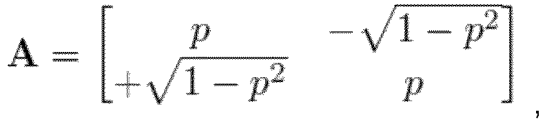 wobei
wobei wobei
wobei wobei
wobei wobei C ex eine erste Kovarianzmatrix ist, die auf ihrer Diagonalen die Mehrzahl von vordefinierten Leistungswerten des Quantisierungsrauschens in der ursprünglichen Domäne aufweist, wobei d 0 und d 1 Matrixkoeffizienten von C ex sind; und wobei C ed eine zweite Kovarianzmatrix ist, die auf ihrer Diagonalen die Mehrzahl von vordefinierten Leistungswerten des Quantisierungsrauschens in der Transformationsdomäne aufweist, wobei c0 und ci Matrixkoeffizienten von C ed sind.
 - Ein Verfahren zum Decodieren eines codierten Audiosignals, um ein decodiertes Audiosignal zu erhalten, wobei das Verfahren folgende Schritte aufweist:Decodieren des codierten Audiosignals, um ein quantisiertes Signal zu erhalten,Dequantisieren des quantisierten Signals, um ein Zwischensignal zu erhalten, das in einer Transformationsdomäne repräsentiert wird, undTransformieren des Zwischensignals von der Transformationsdomäne in eine ursprüngliche Domäne, um das decodierte Audiosignal zu erhalten, das in der ursprünglichen Domäne repräsentiert wird,dadurch gekennzeichnet, dass das Transformieren des Zwischensignals unter Verwendung einer Mehrzahl von vordefinierten Leistungswerten von Quantisierungsrauschen in der ursprünglichen Domäne und unter Verwendung einer Mehrzahl von vordefinierten Leistungswerten des Quantisierungsrauschens in der Transformationsdomäne durchgeführt wird,wobei die ursprüngliche Domäne eine Spektraldomäne ist,wobei das Verfahren das Transformieren des Zwischensignals unter Verwendung einer Transformationsmatrix AT aufweist, wobei das Transformieren des Audioeingangssignals gemäß Folgendem durchgeführt wird:
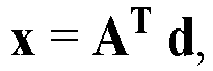 wobei d das Zwischensignal angibt, wobei x das decodierte Audiosignal angibt, wobei AT die Transformationsmatrix in Abhängigkeit von der Mehrzahl von vordefinierten Leistungswerten des Quantisierungsrauschens in der ursprünglichen Domäne und in Abhängigkeit von der Mehrzahl von vordefinierten Leistungswerten des Quantisierungsrauschens in der Transformationsdomäne angibt,wobei AT eine konjugierte transponierte Matrix einer Matrix A ist,wobei die Matrix A gemäß Folgendem definiert ist:
 wobei
wobei wobei
wobei wobei
wobei wobei C ex eine erste Kovarianzmatrix ist, die auf ihrer Diagonalen die Mehrzahl von vordefinierten Leistungswerten des Quantisierungsrauschens in der ursprünglichen Domäne aufweist, wobei d 0 und d 1 Matrixkoeffizienten von C ex sind, und wobei C ed eine zweite Kovarianzmatrix ist, die auf ihrer Diagonalen die Mehrzahl von vordefinierten Leistungswerten des Quantisierungsrauschens in der Transformationsdomäne aufweist, wobei c0 und ci Matrixkoeffizienten von C ed sind.
 - Computerprogramm zum Implementieren des Verfahrens nach Patentanspruch 5 oder 6, wenn es auf einem Computer oder Signalprozessor ausgeführt wird.
Applications Claiming Priority (2)
| Application Number | Priority Date | Filing Date | Title |
|---|---|---|---|
| EP18197377 | 2018-09-27 | ||
| US16/170,151 US11295750B2 (en) | 2018-09-27 | 2018-10-25 | Apparatus and method for noise shaping using subspace projections for low-rate coding of speech and audio |
Publications (2)
| Publication Number | Publication Date |
|---|---|
| EP3629327A1 EP3629327A1 (de) | 2020-04-01 |
| EP3629327B1 true EP3629327B1 (de) | 2024-11-27 |
Family
ID=68069678
Family Applications (1)
| Application Number | Title | Priority Date | Filing Date |
|---|---|---|---|
| EP19199807.9A Active EP3629327B1 (de) | 2018-09-27 | 2019-09-26 | Vorrichtung und verfahren zur rauschformung unter verwendung von unterraumprojektionen zur niederratigen codierung von sprache und audio |
Country Status (1)
| Country | Link |
|---|---|
| EP (1) | EP3629327B1 (de) |
Family Cites Families (2)
| Publication number | Priority date | Publication date | Assignee | Title |
|---|---|---|---|---|
| US6636830B1 (en) * | 2000-11-22 | 2003-10-21 | Vialta Inc. | System and method for noise reduction using bi-orthogonal modified discrete cosine transform |
| WO2011044700A1 (en) * | 2009-10-15 | 2011-04-21 | Voiceage Corporation | Simultaneous time-domain and frequency-domain noise shaping for tdac transforms |
-
2019
- 2019-09-26 EP EP19199807.9A patent/EP3629327B1/de active Active
Also Published As
| Publication number | Publication date |
|---|---|
| EP3629327A1 (de) | 2020-04-01 |
Similar Documents
| Publication | Publication Date | Title |
|---|---|---|
| EP2382621B1 (de) | Verfahren und vorrichtung zur erzeugung einer erweiterungsschicht in einem multikanal-audiokodierungssystem | |
| US8219408B2 (en) | Audio signal decoder and method for producing a scaled reconstructed audio signal | |
| US8200496B2 (en) | Audio signal decoder and method for producing a scaled reconstructed audio signal | |
| US11616954B2 (en) | Signal encoding method and apparatus and signal decoding method and apparatus | |
| EP2677519B1 (de) | Sprachdekodiervorrichtung, sprachkodiervorrichtung, sprachdekodierverfahren, sprachkodierverfahren, sprachdekodierprogramm und sprachkodierprogramm | |
| EP2382627B1 (de) | Selektive skalierungsmaskenberechnung auf der basis von spitzendetektion | |
| US10194151B2 (en) | Signal encoding method and apparatus and signal decoding method and apparatus | |
| EP3405950B1 (de) | Stereokodierung von audio signalen unter verwendung von einer ild-basierten normalisierung vor einer mid-/side-entscheidung | |
| EP3544005B1 (de) | Audiocodierung mit geditherten quantisierung | |
| EP3550563B1 (de) | Encoder, decoder, encodierungsverfahren, decodierungsverfahren und zugehörige programme | |
| US11295750B2 (en) | Apparatus and method for noise shaping using subspace projections for low-rate coding of speech and audio | |
| EP3629327B1 (de) | Vorrichtung und verfahren zur rauschformung unter verwendung von unterraumprojektionen zur niederratigen codierung von sprache und audio | |
| JPWO2008072733A1 (ja) | 符号化装置および符号化方法 | |
| EP3008726B1 (de) | Vorrichtung und verfahren zur audiosignalhüllkurvencodierung, verarbeitung und decodierung durch modellierung einer repräsentation einer kumulativen summe unter verwendung von verteilungsquantisierung und -codierung | |
| CA2914418C (en) | Apparatus and method for audio signal envelope encoding, processing and decoding by splitting the audio signal envelope employing distribution quantization and coding | |
| Lee et al. | KLT-based adaptive entropy-constrained quantization with universal arithmetic coding | |
| KR20160098597A (ko) | 통신 시스템에서 신호 코덱 장치 및 방법 |
Legal Events
| Date | Code | Title | Description |
|---|---|---|---|
| PUAI | Public reference made under article 153(3) epc to a published international application that has entered the european phase |
Free format text: ORIGINAL CODE: 0009012 |
|
| STAA | Information on the status of an ep patent application or granted ep patent |
Free format text: STATUS: THE APPLICATION HAS BEEN PUBLISHED |
|
| AK | Designated contracting states |
Kind code of ref document: A1 Designated state(s): AL AT BE BG CH CY CZ DE DK EE ES FI FR GB GR HR HU IE IS IT LI LT LU LV MC MK MT NL NO PL PT RO RS SE SI SK SM TR |
|
| AX | Request for extension of the european patent |
Extension state: BA ME |
|
| STAA | Information on the status of an ep patent application or granted ep patent |
Free format text: STATUS: REQUEST FOR EXAMINATION WAS MADE |
|
| 17P | Request for examination filed |
Effective date: 20201001 |
|
| RBV | Designated contracting states (corrected) |
Designated state(s): AL AT BE BG CH CY CZ DE DK EE ES FI FR GB GR HR HU IE IS IT LI LT LU LV MC MK MT NL NO PL PT RO RS SE SI SK SM TR |
|
| RAP1 | Party data changed (applicant data changed or rights of an application transferred) |
Owner name: FRAUNHOFER-GESELLSCHAFT ZUR FOERDERUNG DER ANGEWANDTEN FORSCHUNG E.V. Owner name: FRIEDRICH-ALEXANDER-UNIVERSITAET ERLANGEN-NUERNBERG |
|
| STAA | Information on the status of an ep patent application or granted ep patent |
Free format text: STATUS: EXAMINATION IS IN PROGRESS |
|
| 17Q | First examination report despatched |
Effective date: 20211203 |
|
| RAP3 | Party data changed (applicant data changed or rights of an application transferred) |
Owner name: FRIEDRICH-ALEXANDER-UNIVERSITAET ERLANGEN-NUERNBERG Owner name: FRAUNHOFER-GESELLSCHAFT ZUR FOERDERUNG DER ANGEWANDTEN FORSCHUNG E.V. |
|
| GRAP | Despatch of communication of intention to grant a patent |
Free format text: ORIGINAL CODE: EPIDOSNIGR1 |
|
| STAA | Information on the status of an ep patent application or granted ep patent |
Free format text: STATUS: GRANT OF PATENT IS INTENDED |
|
| INTG | Intention to grant announced |
Effective date: 20240618 |
|
| GRAS | Grant fee paid |
Free format text: ORIGINAL CODE: EPIDOSNIGR3 |
|
| GRAA | (expected) grant |
Free format text: ORIGINAL CODE: 0009210 |
|
| STAA | Information on the status of an ep patent application or granted ep patent |
Free format text: STATUS: THE PATENT HAS BEEN GRANTED |
|
| AK | Designated contracting states |
Kind code of ref document: B1 Designated state(s): AL AT BE BG CH CY CZ DE DK EE ES FI FR GB GR HR HU IE IS IT LI LT LU LV MC MK MT NL NO PL PT RO RS SE SI SK SM TR |
|
| REG | Reference to a national code |
Ref country code: GB Ref legal event code: FG4D |
|
| REG | Reference to a national code |
Ref country code: CH Ref legal event code: EP |
|
| REG | Reference to a national code |
Ref country code: DE Ref legal event code: R081 Ref document number: 602019062501 Country of ref document: DE Owner name: FRIEDRICH-ALEXANDER-UNIVERSITAET ERLANGEN-NUER, DE Free format text: FORMER OWNER: ANMELDERANGABEN UNKLAR / UNVOLLSTAENDIG, 80297 MUENCHEN, DE Ref country code: DE Ref legal event code: R081 Ref document number: 602019062501 Country of ref document: DE Owner name: FRAUNHOFER-GESELLSCHAFT ZUR FOERDERUNG DER ANG, DE Free format text: FORMER OWNER: ANMELDERANGABEN UNKLAR / UNVOLLSTAENDIG, 80297 MUENCHEN, DE |
|
| REG | Reference to a national code |
Ref country code: DE Ref legal event code: R096 Ref document number: 602019062501 Country of ref document: DE |
|
| REG | Reference to a national code |
Ref country code: IE Ref legal event code: FG4D |
|
| REG | Reference to a national code |
Ref country code: LT Ref legal event code: MG9D |
|
| REG | Reference to a national code |
Ref country code: NL Ref legal event code: MP Effective date: 20241127 |
|
| PG25 | Lapsed in a contracting state [announced via postgrant information from national office to epo] |
Ref country code: IS Free format text: LAPSE BECAUSE OF FAILURE TO SUBMIT A TRANSLATION OF THE DESCRIPTION OR TO PAY THE FEE WITHIN THE PRESCRIBED TIME-LIMIT Effective date: 20250327 Ref country code: HR Free format text: LAPSE BECAUSE OF FAILURE TO SUBMIT A TRANSLATION OF THE DESCRIPTION OR TO PAY THE FEE WITHIN THE PRESCRIBED TIME-LIMIT Effective date: 20241127 Ref country code: PT Free format text: LAPSE BECAUSE OF FAILURE TO SUBMIT A TRANSLATION OF THE DESCRIPTION OR TO PAY THE FEE WITHIN THE PRESCRIBED TIME-LIMIT Effective date: 20250327 |
|
| PG25 | Lapsed in a contracting state [announced via postgrant information from national office to epo] |
Ref country code: FI Free format text: LAPSE BECAUSE OF FAILURE TO SUBMIT A TRANSLATION OF THE DESCRIPTION OR TO PAY THE FEE WITHIN THE PRESCRIBED TIME-LIMIT Effective date: 20241127 Ref country code: NL Free format text: LAPSE BECAUSE OF FAILURE TO SUBMIT A TRANSLATION OF THE DESCRIPTION OR TO PAY THE FEE WITHIN THE PRESCRIBED TIME-LIMIT Effective date: 20241127 |
|
| REG | Reference to a national code |
Ref country code: AT Ref legal event code: MK05 Ref document number: 1746524 Country of ref document: AT Kind code of ref document: T Effective date: 20241127 |
|
| PG25 | Lapsed in a contracting state [announced via postgrant information from national office to epo] |
Ref country code: BG Free format text: LAPSE BECAUSE OF FAILURE TO SUBMIT A TRANSLATION OF THE DESCRIPTION OR TO PAY THE FEE WITHIN THE PRESCRIBED TIME-LIMIT Effective date: 20241127 |
|
| PG25 | Lapsed in a contracting state [announced via postgrant information from national office to epo] |
Ref country code: ES Free format text: LAPSE BECAUSE OF FAILURE TO SUBMIT A TRANSLATION OF THE DESCRIPTION OR TO PAY THE FEE WITHIN THE PRESCRIBED TIME-LIMIT Effective date: 20241127 |
|
| PG25 | Lapsed in a contracting state [announced via postgrant information from national office to epo] |
Ref country code: NO Free format text: LAPSE BECAUSE OF FAILURE TO SUBMIT A TRANSLATION OF THE DESCRIPTION OR TO PAY THE FEE WITHIN THE PRESCRIBED TIME-LIMIT Effective date: 20250227 |
|
| PG25 | Lapsed in a contracting state [announced via postgrant information from national office to epo] |
Ref country code: GR Free format text: LAPSE BECAUSE OF FAILURE TO SUBMIT A TRANSLATION OF THE DESCRIPTION OR TO PAY THE FEE WITHIN THE PRESCRIBED TIME-LIMIT Effective date: 20250228 Ref country code: LV Free format text: LAPSE BECAUSE OF FAILURE TO SUBMIT A TRANSLATION OF THE DESCRIPTION OR TO PAY THE FEE WITHIN THE PRESCRIBED TIME-LIMIT Effective date: 20241127 Ref country code: AT Free format text: LAPSE BECAUSE OF FAILURE TO SUBMIT A TRANSLATION OF THE DESCRIPTION OR TO PAY THE FEE WITHIN THE PRESCRIBED TIME-LIMIT Effective date: 20241127 |
|
| PG25 | Lapsed in a contracting state [announced via postgrant information from national office to epo] |
Ref country code: PL Free format text: LAPSE BECAUSE OF FAILURE TO SUBMIT A TRANSLATION OF THE DESCRIPTION OR TO PAY THE FEE WITHIN THE PRESCRIBED TIME-LIMIT Effective date: 20241127 |
|
| PG25 | Lapsed in a contracting state [announced via postgrant information from national office to epo] |
Ref country code: RS Free format text: LAPSE BECAUSE OF FAILURE TO SUBMIT A TRANSLATION OF THE DESCRIPTION OR TO PAY THE FEE WITHIN THE PRESCRIBED TIME-LIMIT Effective date: 20250227 |
|
| PG25 | Lapsed in a contracting state [announced via postgrant information from national office to epo] |
Ref country code: SM Free format text: LAPSE BECAUSE OF FAILURE TO SUBMIT A TRANSLATION OF THE DESCRIPTION OR TO PAY THE FEE WITHIN THE PRESCRIBED TIME-LIMIT Effective date: 20241127 |
|
| PG25 | Lapsed in a contracting state [announced via postgrant information from national office to epo] |
Ref country code: DK Free format text: LAPSE BECAUSE OF FAILURE TO SUBMIT A TRANSLATION OF THE DESCRIPTION OR TO PAY THE FEE WITHIN THE PRESCRIBED TIME-LIMIT Effective date: 20241127 |
|
| PG25 | Lapsed in a contracting state [announced via postgrant information from national office to epo] |
Ref country code: EE Free format text: LAPSE BECAUSE OF FAILURE TO SUBMIT A TRANSLATION OF THE DESCRIPTION OR TO PAY THE FEE WITHIN THE PRESCRIBED TIME-LIMIT Effective date: 20241127 |
|
| PG25 | Lapsed in a contracting state [announced via postgrant information from national office to epo] |
Ref country code: RO Free format text: LAPSE BECAUSE OF FAILURE TO SUBMIT A TRANSLATION OF THE DESCRIPTION OR TO PAY THE FEE WITHIN THE PRESCRIBED TIME-LIMIT Effective date: 20241127 |
|
| PG25 | Lapsed in a contracting state [announced via postgrant information from national office to epo] |
Ref country code: SK Free format text: LAPSE BECAUSE OF FAILURE TO SUBMIT A TRANSLATION OF THE DESCRIPTION OR TO PAY THE FEE WITHIN THE PRESCRIBED TIME-LIMIT Effective date: 20241127 |
|
| PG25 | Lapsed in a contracting state [announced via postgrant information from national office to epo] |
Ref country code: CZ Free format text: LAPSE BECAUSE OF FAILURE TO SUBMIT A TRANSLATION OF THE DESCRIPTION OR TO PAY THE FEE WITHIN THE PRESCRIBED TIME-LIMIT Effective date: 20241127 |
|
| PG25 | Lapsed in a contracting state [announced via postgrant information from national office to epo] |
Ref country code: IT Free format text: LAPSE BECAUSE OF FAILURE TO SUBMIT A TRANSLATION OF THE DESCRIPTION OR TO PAY THE FEE WITHIN THE PRESCRIBED TIME-LIMIT Effective date: 20241127 |
|
| REG | Reference to a national code |
Ref country code: DE Ref legal event code: R097 Ref document number: 602019062501 Country of ref document: DE |
|
| PG25 | Lapsed in a contracting state [announced via postgrant information from national office to epo] |
Ref country code: SE Free format text: LAPSE BECAUSE OF FAILURE TO SUBMIT A TRANSLATION OF THE DESCRIPTION OR TO PAY THE FEE WITHIN THE PRESCRIBED TIME-LIMIT Effective date: 20241127 |
|
| PLBE | No opposition filed within time limit |
Free format text: ORIGINAL CODE: 0009261 |
|
| STAA | Information on the status of an ep patent application or granted ep patent |
Free format text: STATUS: NO OPPOSITION FILED WITHIN TIME LIMIT |
|
| PGFP | Annual fee paid to national office [announced via postgrant information from national office to epo] |
Ref country code: DE Payment date: 20250801 Year of fee payment: 7 |
|
| PGFP | Annual fee paid to national office [announced via postgrant information from national office to epo] |
Ref country code: GB Payment date: 20250927 Year of fee payment: 7 |
|
| PGFP | Annual fee paid to national office [announced via postgrant information from national office to epo] |
Ref country code: FR Payment date: 20250926 Year of fee payment: 7 |
|
| 26N | No opposition filed |
Effective date: 20250828 |