EP3628973B1 - Technologies for autonomous driving quality of service determination and communication - Google Patents
Technologies for autonomous driving quality of service determination and communication Download PDFInfo
- Publication number
- EP3628973B1 EP3628973B1 EP19183095.9A EP19183095A EP3628973B1 EP 3628973 B1 EP3628973 B1 EP 3628973B1 EP 19183095 A EP19183095 A EP 19183095A EP 3628973 B1 EP3628973 B1 EP 3628973B1
- Authority
- EP
- European Patent Office
- Prior art keywords
- route
- computing device
- autonomous
- autonomous driving
- vehicle
- Prior art date
- Legal status (The legal status is an assumption and is not a legal conclusion. Google has not performed a legal analysis and makes no representation as to the accuracy of the status listed.)
- Active
Links
Images


Classifications
-
- G—PHYSICS
- G05—CONTROLLING; REGULATING
- G05D—SYSTEMS FOR CONTROLLING OR REGULATING NON-ELECTRIC VARIABLES
- G05D1/00—Control of position, course, altitude or attitude of land, water, air or space vehicles, e.g. using automatic pilots
- G05D1/02—Control of position or course in two dimensions
- G05D1/021—Control of position or course in two dimensions specially adapted to land vehicles
- G05D1/0212—Control of position or course in two dimensions specially adapted to land vehicles with means for defining a desired trajectory
- G05D1/0214—Control of position or course in two dimensions specially adapted to land vehicles with means for defining a desired trajectory in accordance with safety or protection criteria, e.g. avoiding hazardous areas
-
- G—PHYSICS
- G01—MEASURING; TESTING
- G01C—MEASURING DISTANCES, LEVELS OR BEARINGS; SURVEYING; NAVIGATION; GYROSCOPIC INSTRUMENTS; PHOTOGRAMMETRY OR VIDEOGRAMMETRY
- G01C21/00—Navigation; Navigational instruments not provided for in groups G01C1/00 - G01C19/00
- G01C21/26—Navigation; Navigational instruments not provided for in groups G01C1/00 - G01C19/00 specially adapted for navigation in a road network
- G01C21/34—Route searching; Route guidance
- G01C21/3407—Route searching; Route guidance specially adapted for specific applications
-
- G—PHYSICS
- G01—MEASURING; TESTING
- G01C—MEASURING DISTANCES, LEVELS OR BEARINGS; SURVEYING; NAVIGATION; GYROSCOPIC INSTRUMENTS; PHOTOGRAMMETRY OR VIDEOGRAMMETRY
- G01C21/00—Navigation; Navigational instruments not provided for in groups G01C1/00 - G01C19/00
- G01C21/26—Navigation; Navigational instruments not provided for in groups G01C1/00 - G01C19/00 specially adapted for navigation in a road network
- G01C21/34—Route searching; Route guidance
- G01C21/3407—Route searching; Route guidance specially adapted for specific applications
- G01C21/3415—Dynamic re-routing, e.g. recalculating the route when the user deviates from calculated route or after detecting real-time traffic data or accidents
-
- G—PHYSICS
- G01—MEASURING; TESTING
- G01C—MEASURING DISTANCES, LEVELS OR BEARINGS; SURVEYING; NAVIGATION; GYROSCOPIC INSTRUMENTS; PHOTOGRAMMETRY OR VIDEOGRAMMETRY
- G01C21/00—Navigation; Navigational instruments not provided for in groups G01C1/00 - G01C19/00
- G01C21/26—Navigation; Navigational instruments not provided for in groups G01C1/00 - G01C19/00 specially adapted for navigation in a road network
- G01C21/34—Route searching; Route guidance
- G01C21/3453—Special cost functions, i.e. other than distance or default speed limit of road segments
- G01C21/3461—Preferred or disfavoured areas, e.g. dangerous zones, toll or emission zones, intersections, manoeuvre types or segments such as motorways, toll roads or ferries
-
- G—PHYSICS
- G01—MEASURING; TESTING
- G01C—MEASURING DISTANCES, LEVELS OR BEARINGS; SURVEYING; NAVIGATION; GYROSCOPIC INSTRUMENTS; PHOTOGRAMMETRY OR VIDEOGRAMMETRY
- G01C21/00—Navigation; Navigational instruments not provided for in groups G01C1/00 - G01C19/00
- G01C21/26—Navigation; Navigational instruments not provided for in groups G01C1/00 - G01C19/00 specially adapted for navigation in a road network
- G01C21/34—Route searching; Route guidance
- G01C21/3453—Special cost functions, i.e. other than distance or default speed limit of road segments
- G01C21/3492—Special cost functions, i.e. other than distance or default speed limit of road segments employing speed data or traffic data, e.g. real-time or historical
-
- G—PHYSICS
- G05—CONTROLLING; REGULATING
- G05D—SYSTEMS FOR CONTROLLING OR REGULATING NON-ELECTRIC VARIABLES
- G05D1/00—Control of position, course, altitude or attitude of land, water, air or space vehicles, e.g. using automatic pilots
- G05D1/02—Control of position or course in two dimensions
- G05D1/021—Control of position or course in two dimensions specially adapted to land vehicles
- G05D1/0231—Control of position or course in two dimensions specially adapted to land vehicles using optical position detecting means
-
- G—PHYSICS
- G05—CONTROLLING; REGULATING
- G05D—SYSTEMS FOR CONTROLLING OR REGULATING NON-ELECTRIC VARIABLES
- G05D1/00—Control of position, course, altitude or attitude of land, water, air or space vehicles, e.g. using automatic pilots
- G05D1/02—Control of position or course in two dimensions
- G05D1/021—Control of position or course in two dimensions specially adapted to land vehicles
- G05D1/0255—Control of position or course in two dimensions specially adapted to land vehicles using acoustic signals, e.g. ultra-sonic singals
-
- G—PHYSICS
- G05—CONTROLLING; REGULATING
- G05D—SYSTEMS FOR CONTROLLING OR REGULATING NON-ELECTRIC VARIABLES
- G05D1/00—Control of position, course, altitude or attitude of land, water, air or space vehicles, e.g. using automatic pilots
- G05D1/02—Control of position or course in two dimensions
- G05D1/021—Control of position or course in two dimensions specially adapted to land vehicles
- G05D1/0257—Control of position or course in two dimensions specially adapted to land vehicles using a radar
-
- G—PHYSICS
- G05—CONTROLLING; REGULATING
- G05D—SYSTEMS FOR CONTROLLING OR REGULATING NON-ELECTRIC VARIABLES
- G05D1/00—Control of position, course, altitude or attitude of land, water, air or space vehicles, e.g. using automatic pilots
- G05D1/02—Control of position or course in two dimensions
- G05D1/021—Control of position or course in two dimensions specially adapted to land vehicles
- G05D1/0276—Control of position or course in two dimensions specially adapted to land vehicles using signals provided by a source external to the vehicle
- G05D1/0285—Control of position or course in two dimensions specially adapted to land vehicles using signals provided by a source external to the vehicle using signals transmitted via a public communication network, e.g. GSM network
-
- G—PHYSICS
- G06—COMPUTING OR CALCULATING; COUNTING
- G06Q—INFORMATION AND COMMUNICATION TECHNOLOGY [ICT] SPECIALLY ADAPTED FOR ADMINISTRATIVE, COMMERCIAL, FINANCIAL, MANAGERIAL OR SUPERVISORY PURPOSES; SYSTEMS OR METHODS SPECIALLY ADAPTED FOR ADMINISTRATIVE, COMMERCIAL, FINANCIAL, MANAGERIAL OR SUPERVISORY PURPOSES, NOT OTHERWISE PROVIDED FOR
- G06Q10/00—Administration; Management
- G06Q10/06—Resources, workflows, human or project management; Enterprise or organisation planning; Enterprise or organisation modelling
- G06Q10/063—Operations research, analysis or management
- G06Q10/0639—Performance analysis of employees; Performance analysis of enterprise or organisation operations
- G06Q10/06393—Score-carding, benchmarking or key performance indicator [KPI] analysis
Definitions
- Modern vehicles may include many types of advanced drive capabilities. Those capabilities allow the vehicle to perform movements without direct control of the driver. For example, some vehicles include parking assist, which allows the vehicle to control acceleration, brake, and steering inputs required to move the vehicle into a nearby parking spot. Some vehicles include smart cruise control or active collision warning and avoidance systems that may detect nearby obstructions and/or initiate evasive actions. Indeed, some vehicles include full self-driving capabilities. SAE International and the National Highway Traffic Safety Administration (NHTSA) have proposed a six-level classification system for different levels of vehicle automation, ranging from Level 0 (no automation) to Level 5 (full automation).
- US 9 796 388 B2 discloses an operating mode for a vehicle determined according to respective control states of each of a plurality of vehicle subsystems that include braking, steering, and propulsion.
- the operating mode is one of manual control, partial manual control, and no manual control.
- a route for the vehicle is determined based in part on the operating mode.
- US 2017/356747 A1 discloses a method for determining an ability of an autonomous vehicle to safely or robustly travel a road feature or a road segment or a route that is considered for the autonomous vehicle as of a time or range of times. The determination is made based on properties of the environment in which the autonomous vehicle travels.
- references in the specification to "one embodiment,” “an embodiment,” “an illustrative embodiment,” etc., indicate that the embodiment described may include a particular feature, structure, or characteristic, but every embodiment may or may not necessarily include that particular feature, structure, or characteristic. Moreover, such phrases are not necessarily referring to the same embodiment. Further, when a particular feature, structure, or characteristic is described in connection with an embodiment, it is submitted that it is within the knowledge of one skilled in the art to effect such feature, structure, or characteristic in connection with other embodiments whether or not explicitly described.
- items included in a list in the form of "at least one of A, B, and C” can mean (A); (B); (C): (A and B); (A and C); (B and C); or (A, B, and C).
- items listed in the form of "at least one of A, B, or C” can mean (A); (B); (C): (A and B); (A and C); (B and C); or (A, B, and C).
- the disclosed embodiments may be implemented, in some cases, in hardware, firmware, software, or any combination thereof.
- the disclosed embodiments may also be implemented as instructions carried by or stored on one or more transitory or non-transitory machine-readable (e.g., computer-readable) storage media, which may be read and executed by one or more processors.
- a machine-readable storage medium may be embodied as any storage device, mechanism, or other physical structure for storing or transmitting information in a form readable by a machine (e.g., a volatile or non-volatile memory, a media disc, or other media device).
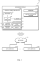
- a system 100 for autonomous driving quality of service (QoS) determination and communication includes an advanced vehicle 102 that includes a vehicle computing device 104.
- the vehicle computing device 104 may communicate with one or more external data services 110 over a network 112.
- the vehicle computing device 104 determines multiple route segments for potential routes to a destination.
- the vehicle computing device 104 determines an autonomous driving quality of service (QoS) score for each route segment, which is based on the driving autonomy level achievable by the advanced vehicle 102 for each route segment. Based on the QoS scores, the vehicle computing device 104 determines a proposed route to the destination, which may be confirmed by the user.
- QoS autonomous driving quality of service
- the vehicle computing device 104 updates QoS scores and the proposed route.
- the system 100 may allow the user to select a route to a destination based on the autonomous driving level achievable for each route segment, which may improve the convenience and/or usability of the advanced vehicle 102.
- the system 100 may further incorporate user preferences or other policies in route selection, which may further improve the autonomous driving experience for the user.
- the system 100 may provide a guaranteed autonomous driving QoS for each route segment of a route, which may increase the feasibility or acceptability of autonomous driving for certain users, for example users who are incapable of driving.
- the advanced vehicle 102 may be embodied as any type of car, truck, or other vehicle capable of performing one or more levels of vehicle automation, including driver assistance, partial automation, conditional automation, high automation, or full automation.
- the advanced vehicle 102 may be capable of full autonomous driving from a starting position to a destination position, including full control of acceleration, steering, braking, collision avoidance, and other driving tasks of the advanced vehicle 102.
- the advanced vehicle 102 may be capable of autonomously or semi-autonomously parallel parking the advanced vehicle 102 or other parking assist tasks.
- the advanced vehicle 102 may provide adaptive cruise control, automated collision avoidance, or other automated driver aids.
- the level of vehicle automation achievable by the advanced vehicle 102 for a particular route segment may depend on available map data, weather conditions, vehicle and sensor health, and/or other autonomous driving factors.
- the advanced vehicle 102 includes the vehicle computing device 104, as well as one or more sensors 106 and a motor/actuator system 108.
- the vehicle computing device 104 may be embodied as any type of computation or computer device capable of performing the functions described herein, including, without limitation, a computer, an electronic control unit (ECU), an in-vehicle infotainment (IVI) device, a multiprocessor system, a server, a rack-mounted server, a blade server, a laptop computer, a notebook computer, a network appliance, a web appliance, a distributed computing system, a processor-based system, and/or a consumer electronic device.
- the vehicle computing device 104 illustratively includes a processor 120, an input/output subsystem 122, a memory 124, a data storage device 126, and communication circuitry 128.
- the vehicle computing device 104 may include other or additional components, such as those commonly found in a vehicle computer (e.g., various input/output devices), in other embodiments. Additionally, in some embodiments, one or more of the illustrative components may be incorporated in, or otherwise form a portion of, another component. For example, the memory 124, or portions thereof, may be incorporated in the processor 120 in some embodiments.
- the processor 120 may be embodied as any type of processor capable of performing the functions described herein.
- the processor 120 may be embodied as a single or multi-core processor(s), digital signal processor, microcontroller, or other processor or processing/controlling circuit.
- the memory 124 may be embodied as any type of volatile or non-volatile memory or data storage capable of performing the functions described herein. In operation, the memory 124 may store various data and software used during operation of the vehicle computing device 104 such as operating systems, applications, programs, libraries, and drivers.
- the memory 124 is communicatively coupled to the processor 120 via the I/O subsystem 122, which may be embodied as circuitry and/or components to facilitate input/output operations with the processor 120, the memory 124, and other components of the vehicle computing device 104.
- the I/O subsystem 122 may be embodied as, or otherwise include, memory controller hubs, input/output control hubs, firmware devices, communication links (i.e., point-to-point links, bus links, wires, cables, light guides, printed circuit board traces, etc.) and/or other components and subsystems to facilitate the input/output operations.
- the I/O subsystem 122 may form a portion of a system-on-a-chip (SoC) and be incorporated, along with the processor 120, the memory 124, and other components of the vehicle computing device 104, on a single integrated circuit chip.
- SoC system-on-a-chip
- the data storage device 126 may be embodied as any type of device or devices configured for short-term or long-term storage of data such as, for example, memory devices and circuits, memory cards, hard disk drives, solid-state drives, or other data storage devices.
- the communication circuitry 128 of the vehicle computing device 104 may be embodied as any communication circuit, device, or collection thereof, capable of enabling communications between the vehicle computing device 104, the data services 110, and/or other remote devices over the network 112.
- the communication circuitry 128 may be configured to use any one or more communication technology (e.g., wired or wireless communications) and associated protocols (e.g., Ethernet, Bluetooth ® , Wi-Fi ® , WiMAX, LTE, etc.) to effect such communication.
- the vehicle computing device 104 also includes a display 130, a location subsystem 132, and one or more peripheral devices 134.
- the display 130 of the vehicle computing device 104 may be embodied as any type of display capable of displaying digital information, such as a liquid crystal display (LCD), a light emitting diode (LED), a plasma display, a cathode ray tube (CRT), or other type of display device.
- the display 130 may be used to present route information and other data to a user of the advanced vehicle 102, and in some embodiments the display 130 may include a touchscreen or other input device to receive user input.
- the display 130 may be embodied as one or more separate components coupled to the vehicle computing device 104, such as an instrument cluster, an in-vehicle infotainment (IVI) device, or another display in a cabin of the advanced vehicle 102.
- an instrument cluster such as an instrument cluster, an in-vehicle infotainment (IVI) device, or another display in a cabin of the advanced vehicle 102.
- IVI in-vehicle infotainment
- the location subsystem 132 of the vehicle computing device 104 may be embodied as any type of circuit capable of determining the precise or approximate position of the vehicle computing device 104 and, thus, the advanced vehicle 102.
- the location subsystem 132 may be embodied as a global positioning system (GPS) receiver, capable of determining the precise coordinates of the vehicle computing device 104.
- GPS global positioning system
- the location subsystem 132 may triangulate or trilaterate the position of the vehicle computing device 104 using distances or angles to cellular network towers with known positions, provided by the communication circuitry 128.
- the location subsystem 132 may determine the approximate position of the vehicle computing device 104 based on association to wireless networks with known positions, using the communication circuitry 128.
- the advanced vehicle 102 also includes multiple sensors 106 and a motor/actuator system 108.
- the sensors 106 may be embodied as any sensor or sensors capable of providing information about the position, nearby objects, or other attributes of the physical environment of the advanced vehicle 102 to the vehicle computing device 104.
- the sensors 106 may include ultrasound, infrared, or laser rangefinders, visible- or infrared-light cameras, three-dimensional LIDAR sensors, and/or RADAR sensors.
- the sensors 106 may include short-range communications sensors capable of communication or identification of other advanced vehicles 102, such as visible light communication sensors.
- the sensors 106 may also provide sensor health data or other diagnostic data to the vehicle computing device 104.
- the motor/actuator system 108 includes any control system capable of controlling movement of the advanced vehicle 102.
- the motor/actuator system 108 may include motor controllers, actuators, traction motors, and/or any other components that control the acceleration, braking, and steering of the advanced vehicle 102.
- Each external data service 110 may be embodied as any computing device, or collection of computing devices, capable of providing information relevant to autonomous driving factors to the vehicle computing device 104.
- each external data service 110 may be embodied as a single server computing device or a collection of servers and associated devices.
- each external data service 110 may be embodied as a "virtual server" formed from multiple computing devices distributed across the network 112 and operating in a public or private cloud.
- each external data service 110 is illustrated in FIG. 1 as embodied as a single server computing device, it should be appreciated that each external data service 110 may be embodied as multiple devices cooperating together to facilitate the functionality described below.
- each external data service 110 may include components and features similar to the vehicle computing device 104, such as a processor, I/O subsystem, memory, data storage, communication circuitry, and various peripheral devices, which are not illustrated in FIG. 1 for clarity of the present description.
- the vehicle computing device 104 establishes an environment 200 during operation.
- the illustrative environment 200 includes a pathfinder 202, a segment analyzer 206, a path ranker 212, a user interface 216, and an in-trip updater 218.
- the various components of the environment 200 may be embodied as hardware, firmware, software, or a combination thereof.
- one or more of the components of the environment 200 may be embodied as circuitry or collection of electrical devices (e.g., pathfinder circuitry 202, segment analyzer circuitry 206, path ranker circuitry 212, user interface circuitry 216, and/or in-trip updater circuitry 218).
- one or more of the pathfinder circuitry 202, the segment analyzer circuitry 206, the path ranker circuitry 212, the user interface circuitry 216, and/or the in-trip updater circuitry 218 may form a portion of one or more of the processor 120, the I/O subsystem 122, and/or other components of the vehicle computing device 104. Additionally, in some embodiments, one or more of the illustrative components may form a portion of another component and/or one or more of the illustrative components may be independent of one another.
- the user interface 216 is configured to receive a requested destination from a user of the vehicle computing device 104 (e.g., a driver, passenger, or other occupant of the advanced vehicle 102).
- the user interface 216 may be further configured to display a proposed route to the user and to receive a selected route from the user in response to displaying the proposed route.
- the proposed route may be determined as described further below.
- the user interface 216 may be further configured to alert the user of a change in the autonomous quality of service score associated with an upcoming route segment during a trip by the advanced vehicle 102.
- the pathfinder 202 is configured to determine multiple route segments 204 of one or more routes to the destination. As described above, the destination may be requested by the user of the vehicle computing device 104.
- the segment analyzer 206 is configured to determine, for each of the route segments 204, one or more associated autonomous driving factors 208.
- Each autonomous driving factor 208 is a numeric value arranged to be indicative of an autonomy level achievable by the advanced vehicle 102 for the associated route segment 204 and may include high-definition map availability, weather conditions, road conditions, traffic conditions, sensor capabilities, sensor health, and/or other factors.
- the segment analyzer 206 is further configured to determine, for each route segment 204, an autonomous quality of service (QoS) score 210 based on the associated autonomous driving factors 208.
- Each autonomous QoS score 210 may be determined, for example, as a weighted average of the autonomous driving factors 208 associated with a route segment 204.
- the path ranker 212 is configured to rank multiple routes to the destination based on the autonomous QoS scores 210 associated with the route segments 204 of each route.
- the routes may be ranked based on one or more user policies 214, which may include a predetermined threshold autonomous QoS score 210, variation in autonomous QoS scores 210, historic driving data of the user, total time of the route, total distance of the route, or other criteria associated with the route.
- the path ranker 212 is further configured to select a proposed route based on the ranking, which may be displayed by the user interface 216 as described above.
- the in-trip updater 218 is configured to monitor the autonomous driving factors 208 for each of the route segments 204 during a trip by the advanced vehicle 102. In response to changes in the autonomous driving factors 208, the autonomous QoS scores 210 are updated, the ranking of the routes to the destination is updated, and a proposed re-routing is determined in response to updating the ranking.
- the vehicle computing device 104 may execute a method 300 for autonomous vehicle QoS determination and communication. It should be appreciated that, in some embodiments, the operations of the method 300 may be performed by one or more components of the environment 200 of the vehicle computing device 104 as shown in FIG. 2 .
- the method 300 begins with block 302, shown in FIG. 3 , in which the vehicle computing device 104 receives a requested destination from a user of the vehicle computing device 104 (e.g., a driver, passenger, or other occupant of the advanced vehicle 102).
- the user may specify an address, a landmark, a business (e.g., restaurant, retail store, fueling/charging station, etc.), or other destination.
- the destination may be provided by the user with a touch screen, with voice input, or with any other input modality of the vehicle computing device 104.
- the vehicle computing device 104 determines route segments 204 for one or more routes to the destination.
- Each route segment 204 may represent a road, driveway, highway, intersection, interchange, road segment, or other part of a route to the destination.
- the vehicle computing device 104 determines multiple different routes to the destination.
- Certain route segments 204 may be shared between multiple routes to the destination. The routes may start at the current location of the advanced vehicle 102 or at another starting location. Illustrative routes and route segments 204 are shown in FIGS. 5-7 and described below.
- the vehicle computing device 104 determines one or more autonomous driving factors 208 for each route segment 204.
- Each autonomous driving factor 208 is indicative of an autonomy level achievable by the advanced vehicle 102 for that corresponding route segment 204.
- the autonomous driving factors 208 are embodied as numeric values or other data corresponding to autonomy levels such as the autonomy levels specified by SAE International (e.g., numeric values 1 to 5 or scaled equivalents between 0 and 1).
- the autonomous driving factors 208 may be determined based on diagnostic data, status data, or other data generated by the advanced vehicle 102 or based on data received from one or more external data services 110.
- the vehicle computing device 104 may determine high-definition map availability for each route segment 204. Operating the advanced vehicle 102 at higher autonomy levels (e.g., partially autonomy, conditional autonomy, high autonomy, and/or full autonomy) may require high-definition or other detailed map data for the associated route segment 204. Similarly, route segments 204 with less-detailed map data available may require user intervention and/or control of the advanced vehicle 102 and thus indicate a lower autonomy level.
- the vehicle computing device 104 may determine whether high-definition map data is available from an external data service 110 (e.g., a mapping server or other geographic information service) or otherwise accessible by the vehicle computing device 104.
- the value of the autonomous driving factor 208 may be proportional to high-definition map availability for the corresponding route segment 204.
- the vehicle computing device 104 may determine weather conditions for each route segment 204.
- Operating the advanced vehicle 102 at higher autonomy levels may be possible only in certain weather conditions.
- sensor data quality produced by certain sensors 106 of the advanced vehicle 102 may depend on visibility, fog, rain, snow, or other weather conditions.
- the motor/actuator system 108 may require certain weather conditions to control motion of the advanced vehicle 102.
- route segments 204 with certain weather conditions may require user intervention and/or control of the advanced vehicle 102 and thus indicate a lower autonomy level.
- the vehicle computing device 104 may receive weather conditions data from an external data service 110 such as a weather server, from sensors 106 of the advanced vehicle 102, and/or from other sources.
- the value of the autonomous driving factor 208 may be proportional to relative visibility, precipitation, or other weather conditions.
- the vehicle computing device 104 may determine road and/or traffic conditions for each route segment 204.
- the vehicle computing device 104 may identify road closures, traffic hazards, road construction, traffic jams, congestion, or road and/or traffic conditions.
- the autonomy level associated with road and/or traffic conditions may depend on capabilities of the particular advanced vehicle 102. For example, certain advanced vehicles 102 may require user intervention for route segments 204 with traffic hazards, road closures, or other road conditions. As another example, certain advanced vehicles 102 may provide full automation for route segments 204 with slow-speed traffic jams but require user control for route segments 204 with free-flowing traffic.
- the vehicle computing device 104 may receive the road and/or traffic conditions from a data service 110 such as a crowdsourced traffic data server or other data source.
- the vehicle computing device 104 may determine vehicle capabilities and/or health, including sensor 106 availability. For example, operating the advanced vehicle 102 at higher autonomy levels (e.g., partially autonomy, conditional autonomy, high autonomy, and/or full autonomy) may require certain sensors 106 (e.g., camera, lidar, or other sensors) to be operating correctly. If certain sensors 106 are inoperable or otherwise unavailable, the advanced vehicle 102 may require user intervention or control. Thus, the value of the autonomous driving factor 208 may indicate full autonomy (e.g., level 5) if the required sensors 106 are available and the lowest autonomy (e.g., level 0 or level 1) if the required sensors 106 are not avaialable.
- level 5 full autonomy
- level 0 or level 1 e.g., level 1
- the vehicle computing device 104 determines an autonomous driving quality of service (QoS) score for each route segment 204.
- the QoS score may be embodied as a numeric value or other data corresponding to an autonomy level achievable by the advanced vehicle 102 for the corresponding route segment 204.
- each QoS score may be determined as a weighted average of the autonomous driving factors 208 associated with each route segment 204.
- a QoS score may be determined using Equation 1, below. In Equation 1, the QoS score Q is determined using as the sum of the n products of a vector of autonomous driving factors v and a vector of weights w.
- each autonomous driving factor v i may be a numeric value scaled from 1 to 5, corresponding to autonomy level.
- the weights w sum to 1.
- the value of each weight may be determined based on domain knowledge and the particular advanced vehicle 102. For example, sensor health may be weighted more than high-definition map availability, and so on.
- Example calculations of the autonomous QoS score Q are described further below in connection with FIGS. 5-7 .
- the vehicle computing device 104 ranks candidate routes based on the autonomous QoS scores 210 of the route segments 204 of the route and any applicable user policies 214.
- the user policies 214 may include any thresholds, preferences, or other criteria that may be evaluated to rank one potential route over another.
- the vehicle computing device 104 may rank the routes based on autonomy level. For example, in some embodiments, the vehicle computing device 104 may rank a route according to an average autonomy level, a weighted average autonomy level, or another composite autonomy level determined based on the QoS scores 210 of the route segments 204 included in that route.
- vehicle computing device 104 may rank routes by comparing the QoS scores 210 of each route segments 204 to a threshold QoS score 210.
- the user may specified a minimum autonomy level 3 (conditional automation), in which example the vehicle computing device 104 may reject routes that include any route segment 204 with a QoS score 210 below level 3.
- the vehicle computing device 104 may rank the routes based on variation in autonomy level between the route segments 204. For example, a user may prefer that the entire trip remain at the same autonomy level rather than switching between higher and lower autonomy levels for different route segments 204.
- the vehicle computing device 104 may rank the routes based on historic driving data. For example, the vehicle computing device 104 may prefer routes that the user has driven in the past. In some embodiments, in block 326 the vehicle computing device 104 may rank the routes based on length or time of the route. For example, the vehicle computing device 104 may prefer routes that are shorter in time and/or distance.
- routes may be ranked by a weighted average or other combination of one or more user policies 214, for example based on a combination of autonomy level, autonomy level variation, historic data, length of route, and/or time of route.
- the user may provide relative weighting factors for those criteria.
- a ranking value for a route may be determined using Equation 2, below.
- Q i is the QoS score of route segment 204 number i
- Sl is the length of the route segment 204
- St is the total length of all route segments 204 in the route
- F indicates the frequency of use of the route by the user
- VRl indicates variation in autonomy level of the route
- t d is the time to the destination for the route.
- the vehicle computing device 104 displays a proposed route to the user.
- the proposed route may be, for example, the top-ranked route based on the ranking determined in block 318.
- the proposed route may be displayed as a map on the display 130 or otherwise communicated to the user of the advanced vehicle 102.
- the vehicle computing device 104 may display the autonomous QoS score 210 for each route segment 204, for example by displaying an autonomous driving level or other indication of the autonomous QoS score 210.
- the vehicle computing device 104 receives a route selection from the user. For example, the user may accept the proposed route or indicate that the proposed route is not acceptable. The vehicle computing device 104 may receive the route selection with a touch screen, voice input, or any other available input modality of the vehicle computing device 104. In block 332, the vehicle computing device 104 determines whether a route has been selected by the user. If so, the method 300 advances to block 336, described below. If no route has been selected, the method 300 branches to block 334, in which the vehicle computing device 104 may propose an alternate route to the user. For example, the vehicle computing device 104 may select the next-highest-ranked route based on the ranking determined in block 318 or another route determined by the vehicle computing device 104.
- the method 300 After proposing the alternate route, the method 300 loops back to block 328 to display the proposed alternate route to the user and receive a user selection. If no routes remain or a route is otherwise not selected, the vehicle computing device 104 may halt the method 300, indicate an error, or otherwise stop the current user interaction.
- the method 300 advances to block 336, in which the vehicle computing device 104 displays the selected route to the user.
- the route may be displayed as a map on the display 130 or otherwise communicated to the user of the advanced vehicle 102.
- the vehicle computing device 104 may display the autonomous QoS score 210 for each route segment 204, for example by displaying an autonomous driving level or other indication of the autonomous QoS score 210.
- the advanced vehicle 102 drives the selected route using an available autonomy level.
- the available autonomy level depends on the route segment 204 currently being driven by the advanced vehicle 102.
- the autonomy level may be any level of vehicle automation, including driver assistance, partial automation, conditional automation, high automation, or full automation.
- the autonomous driving features of the advanced vehicle 102 may be controlled by the vehicle computing device 104, the motor/actuator system 108, and/or other control systems of the advanced vehicle 102.
- the vehicle computing device 104 may notify the user of changes in autonomy level.
- the vehicle computing device 104 may provide advanced warning to the user when the advanced vehicle 102 nears a route segment 204 with a reduced autonomous QoS score 210 as compared to the current route segment 204.
- the vehicle computing device 104 may notify the user with the display 130, a voice alert, or any other user interface modality.
- the vehicle computing device 104 monitors for updated autonomous driving factors 208.
- the vehicle computing device 104 may monitor for updated diagnostic data, status data, or other data generated by the advanced vehicle 102 or for updated data received from one or more external data services 110.
- the vehicle computing device 104 may monitor for updated high-definition map availability data, updated weather condition data, or updated road or traffic condition data.
- the vehicle computing device 104 may monitor for updated vehicle capability and/or health data, including updated sensor 106 availability data.
- the vehicle computing device 104 determines whether the autonomous driving factors 208 have been updated. If not, the method 300 loops back to block 338 to continue driving the selected route.
- the method 300 loops back to block 316, shown in FIG. 3 , to update the autonomous QoS scores 210 based on the updated autonomous driving factors 208. If the autonomous QoS scores 210 change, the vehicle computing device 104 re-ranks potential routes to the destination and proposes an updated route to the user as described above. The vehicle computing device 104 may continue driving the route and monitoring for updated autonomous driving factors 208 until the advanced vehicle 102 reaches the destination or otherwise ends the current trip.
- diagram 500 illustrates potential routes and route segments 204 for an illustrative trip in an advanced vehicle 102.
- the diagram 500 shows a starting position 502, labeled node A, and a destination 504, labeled node F.
- Nodes B through E represent intersections, waypoints, addresses, or other positions between the starting position 502 and the destination 504.
- Each of those nodes is connected by a route segment 204, which are illustratively labeled segments s 1 through s 6 .
- each route segment 204 may be associated with multiple autonomous driving factors 208.
- Those autonomous driving factors 208 may be processed using Equation 1, above, to determine an autonomous QoS score 210 for each route segment 204.
- Table 1, shown below, illustrates example autonomous driving factors 208 and resulting QoS scores 210 for the illustrative route segments 204 shown in FIG. 5 .
- factor v 1 indicates high-definition map availability
- factor v 2 indicates GPS availability
- factor v 3 indicates sensor health
- factor v 4 indicates road conditions
- factor v 5 indicates weather conditions
- factor v 6 indicates traffic conditions.
- each factor v 1 through v 6 is scaled from 1 to 5, corresponding to potential autonomous driving levels.
- the factors v 1 through v 6 may be embodied as different values and/or scales, such as floating point values from 0.0 (corresponding to autonomous level 1) to 1.0 (corresponding autonomous level 5). Weights w 1 through w 6 correspond to factors v 1 through v 6 and are determined based on domain knowledge and the particular advanced vehicle 102.
- the autonomous QoS scores Q for each segment s 1 through s 6 are determined using Equation 1 as described above and are illustratively rounded to the nearest integer value.
- segment s 1 , s 3 , s 4 , and s 6 have autonomous QoS scores Q corresponding to autonomous driving level 4
- segment s 2 has autonomous QoS score Q corresponding to autonomous driving level 3
- segment s 5 autonomous QoS score Q corresponding to autonomous driving level 5.
- diagram 600 illustrates one potential route 602 from the starting position 502 to the destination 504.
- the route 602 includes route segments s 1 , s 2 , and s 3 .
- the route 602 may be selected, for example, as the path with the shortest distance and/or drive time between the starting position 502 to the destination 504.
- segment s 2 has an autonomous QoS score 210 equivalent to autonomous driving level 3, and thus the advanced vehicle 102 may require increased user supervision/intervention while driving that segment.
- the method 300 may be embodied as various instructions stored on a computer-readable media, which may be executed by the processor 120 and/or other components of the vehicle computing device 104 to cause the vehicle computing device 104 to perform the method 300.
- the computer-readable media may be embodied as any type of media capable of being read by the vehicle computing device 104 including, but not limited to, the memory 124, the data storage device 126, firmware devices, other memory or data storage devices of the vehicle computing device 104, portable media readable by a peripheral device 134 of the vehicle computing device 104, and/or other media.
Landscapes
- Engineering & Computer Science (AREA)
- Radar, Positioning & Navigation (AREA)
- Remote Sensing (AREA)
- Physics & Mathematics (AREA)
- Automation & Control Theory (AREA)
- General Physics & Mathematics (AREA)
- Business, Economics & Management (AREA)
- Aviation & Aerospace Engineering (AREA)
- Human Resources & Organizations (AREA)
- Development Economics (AREA)
- Educational Administration (AREA)
- Economics (AREA)
- Entrepreneurship & Innovation (AREA)
- Strategic Management (AREA)
- Game Theory and Decision Science (AREA)
- Marketing (AREA)
- Electromagnetism (AREA)
- Tourism & Hospitality (AREA)
- General Business, Economics & Management (AREA)
- Theoretical Computer Science (AREA)
- Operations Research (AREA)
- Acoustics & Sound (AREA)
- Quality & Reliability (AREA)
- Navigation (AREA)
- Health & Medical Sciences (AREA)
- Artificial Intelligence (AREA)
- Evolutionary Computation (AREA)
- Medical Informatics (AREA)
- Traffic Control Systems (AREA)
Description
- Modern vehicles may include many types of advanced drive capabilities. Those capabilities allow the vehicle to perform movements without direct control of the driver. For example, some vehicles include parking assist, which allows the vehicle to control acceleration, brake, and steering inputs required to move the vehicle into a nearby parking spot. Some vehicles include smart cruise control or active collision warning and avoidance systems that may detect nearby obstructions and/or initiate evasive actions. Indeed, some vehicles include full self-driving capabilities. SAE International and the National Highway Traffic Safety Administration (NHTSA) have proposed a six-level classification system for different levels of vehicle automation, ranging from Level 0 (no automation) to Level 5 (full automation).
-
US 9 796 388 B2 -
US 2017/356747 A1 discloses a method for determining an ability of an autonomous vehicle to safely or robustly travel a road feature or a road segment or a route that is considered for the autonomous vehicle as of a time or range of times. The determination is made based on properties of the environment in which the autonomous vehicle travels. - The invention is defined by the appended independent claims. Advantageous features of the invention are set out in the accompanying appended dependent claims.
- The concepts described herein are illustrated by way of example and not by way of limitation in the accompanying figures. For simplicity and clarity of illustration, elements illustrated in the figures are not necessarily drawn to scale. Where considered appropriate, reference labels have been repeated among the figures to indicate corresponding or analogous elements.
-
FIG. 1 is a simplified block diagram of at least one embodiment of a system for autonomous vehicle quality of service determination and communication; -
FIG. 2 is a simplified block diagram of at least one embodiment of an environment that may be established by a vehicle computing device the system ofFIG. 1 ; -
FIGS. 3 and4 are a simplified flow diagram of at least one embodiment of a method for autonomous vehicle quality of service determination and communication that may be executed by the vehicle computing device ofFIGS. 1 and2 ; and -
FIGS. 5-7 are schematic diagrams illustrating potential routes and route segments that may be analyzed by the vehicle computing device ofFIGS. 1-2 . - While the concepts of the present disclosure are susceptible to various modifications and alternative forms, specific embodiments thereof have been shown by way of example in the drawings and will be described herein in detail.
- References in the specification to "one embodiment," "an embodiment," "an illustrative embodiment," etc., indicate that the embodiment described may include a particular feature, structure, or characteristic, but every embodiment may or may not necessarily include that particular feature, structure, or characteristic. Moreover, such phrases are not necessarily referring to the same embodiment. Further, when a particular feature, structure, or characteristic is described in connection with an embodiment, it is submitted that it is within the knowledge of one skilled in the art to effect such feature, structure, or characteristic in connection with other embodiments whether or not explicitly described. Additionally, it should be appreciated that items included in a list in the form of "at least one of A, B, and C" can mean (A); (B); (C): (A and B); (A and C); (B and C); or (A, B, and C). Similarly, items listed in the form of "at least one of A, B, or C" can mean (A); (B); (C): (A and B); (A and C); (B and C); or (A, B, and C).
- The disclosed embodiments may be implemented, in some cases, in hardware, firmware, software, or any combination thereof. The disclosed embodiments may also be implemented as instructions carried by or stored on one or more transitory or non-transitory machine-readable (e.g., computer-readable) storage media, which may be read and executed by one or more processors. A machine-readable storage medium may be embodied as any storage device, mechanism, or other physical structure for storing or transmitting information in a form readable by a machine (e.g., a volatile or non-volatile memory, a media disc, or other media device).
- In the drawings, some structural or method features may be shown in specific arrangements and/or orderings. However, it should be appreciated that such specific arrangements and/or orderings may not be required. Rather, in some embodiments, such features may be arranged in a different manner and/or order than shown in the illustrative figures. Additionally, the inclusion of a structural or method feature in a particular figure is not meant to imply that such feature is required in all embodiments and, in some embodiments, may not be included or may be combined with other features.
- Referring now to
FIG. 1 , in an illustrative embodiment, asystem 100 for autonomous driving quality of service (QoS) determination and communication includes anadvanced vehicle 102 that includes avehicle computing device 104. Thevehicle computing device 104 may communicate with one or moreexternal data services 110 over anetwork 112. In use, as described further below, thevehicle computing device 104 determines multiple route segments for potential routes to a destination. Thevehicle computing device 104 determines an autonomous driving quality of service (QoS) score for each route segment, which is based on the driving autonomy level achievable by theadvanced vehicle 102 for each route segment. Based on the QoS scores, thevehicle computing device 104 determines a proposed route to the destination, which may be confirmed by the user. As theadvanced vehicle 102 drives the route to the destination, thevehicle computing device 104 updates QoS scores and the proposed route. Thus, thesystem 100 may allow the user to select a route to a destination based on the autonomous driving level achievable for each route segment, which may improve the convenience and/or usability of theadvanced vehicle 102. Thesystem 100 may further incorporate user preferences or other policies in route selection, which may further improve the autonomous driving experience for the user. In some embodiments, thesystem 100 may provide a guaranteed autonomous driving QoS for each route segment of a route, which may increase the feasibility or acceptability of autonomous driving for certain users, for example users who are incapable of driving. - The
advanced vehicle 102 may be embodied as any type of car, truck, or other vehicle capable of performing one or more levels of vehicle automation, including driver assistance, partial automation, conditional automation, high automation, or full automation. For example, theadvanced vehicle 102 may be capable of full autonomous driving from a starting position to a destination position, including full control of acceleration, steering, braking, collision avoidance, and other driving tasks of theadvanced vehicle 102. As another example, theadvanced vehicle 102 may be capable of autonomously or semi-autonomously parallel parking theadvanced vehicle 102 or other parking assist tasks. As another example, theadvanced vehicle 102 may provide adaptive cruise control, automated collision avoidance, or other automated driver aids. The level of vehicle automation achievable by theadvanced vehicle 102 for a particular route segment may depend on available map data, weather conditions, vehicle and sensor health, and/or other autonomous driving factors. Illustratively, theadvanced vehicle 102 includes thevehicle computing device 104, as well as one ormore sensors 106 and a motor/actuator system 108. - The
vehicle computing device 104 may be embodied as any type of computation or computer device capable of performing the functions described herein, including, without limitation, a computer, an electronic control unit (ECU), an in-vehicle infotainment (IVI) device, a multiprocessor system, a server, a rack-mounted server, a blade server, a laptop computer, a notebook computer, a network appliance, a web appliance, a distributed computing system, a processor-based system, and/or a consumer electronic device. As shown inFIG. 1 , thevehicle computing device 104 illustratively includes aprocessor 120, an input/output subsystem 122, amemory 124, adata storage device 126, andcommunication circuitry 128. Of course, thevehicle computing device 104 may include other or additional components, such as those commonly found in a vehicle computer (e.g., various input/output devices), in other embodiments. Additionally, in some embodiments, one or more of the illustrative components may be incorporated in, or otherwise form a portion of, another component. For example, thememory 124, or portions thereof, may be incorporated in theprocessor 120 in some embodiments. - The
processor 120 may be embodied as any type of processor capable of performing the functions described herein. For example, theprocessor 120 may be embodied as a single or multi-core processor(s), digital signal processor, microcontroller, or other processor or processing/controlling circuit. Similarly, thememory 124 may be embodied as any type of volatile or non-volatile memory or data storage capable of performing the functions described herein. In operation, thememory 124 may store various data and software used during operation of thevehicle computing device 104 such as operating systems, applications, programs, libraries, and drivers. Thememory 124 is communicatively coupled to theprocessor 120 via the I/O subsystem 122, which may be embodied as circuitry and/or components to facilitate input/output operations with theprocessor 120, thememory 124, and other components of thevehicle computing device 104. For example, the I/O subsystem 122 may be embodied as, or otherwise include, memory controller hubs, input/output control hubs, firmware devices, communication links (i.e., point-to-point links, bus links, wires, cables, light guides, printed circuit board traces, etc.) and/or other components and subsystems to facilitate the input/output operations. In some embodiments, the I/O subsystem 122 may form a portion of a system-on-a-chip (SoC) and be incorporated, along with theprocessor 120, thememory 124, and other components of thevehicle computing device 104, on a single integrated circuit chip. - The
data storage device 126 may be embodied as any type of device or devices configured for short-term or long-term storage of data such as, for example, memory devices and circuits, memory cards, hard disk drives, solid-state drives, or other data storage devices. Thecommunication circuitry 128 of thevehicle computing device 104 may be embodied as any communication circuit, device, or collection thereof, capable of enabling communications between thevehicle computing device 104, thedata services 110, and/or other remote devices over thenetwork 112. Thecommunication circuitry 128 may be configured to use any one or more communication technology (e.g., wired or wireless communications) and associated protocols (e.g., Ethernet, Bluetooth®, Wi-Fi®, WiMAX, LTE, etc.) to effect such communication. - As shown, the
vehicle computing device 104 also includes adisplay 130, alocation subsystem 132, and one or moreperipheral devices 134. Thedisplay 130 of thevehicle computing device 104 may be embodied as any type of display capable of displaying digital information, such as a liquid crystal display (LCD), a light emitting diode (LED), a plasma display, a cathode ray tube (CRT), or other type of display device. As described further below, thedisplay 130 may be used to present route information and other data to a user of theadvanced vehicle 102, and in some embodiments thedisplay 130 may include a touchscreen or other input device to receive user input. Although illustrated as being included in thevehicle computing device 104, it should be understood that in some embodiments thedisplay 130 may be embodied as one or more separate components coupled to thevehicle computing device 104, such as an instrument cluster, an in-vehicle infotainment (IVI) device, or another display in a cabin of theadvanced vehicle 102. - The
location subsystem 132 of thevehicle computing device 104 may be embodied as any type of circuit capable of determining the precise or approximate position of thevehicle computing device 104 and, thus, theadvanced vehicle 102. For example, thelocation subsystem 132 may be embodied as a global positioning system (GPS) receiver, capable of determining the precise coordinates of thevehicle computing device 104. In other embodiments, thelocation subsystem 132 may triangulate or trilaterate the position of thevehicle computing device 104 using distances or angles to cellular network towers with known positions, provided by thecommunication circuitry 128. In other embodiments, thelocation subsystem 132 may determine the approximate position of thevehicle computing device 104 based on association to wireless networks with known positions, using thecommunication circuitry 128. - As described above, the
advanced vehicle 102 also includesmultiple sensors 106 and a motor/actuator system 108. Thesensors 106 may be embodied as any sensor or sensors capable of providing information about the position, nearby objects, or other attributes of the physical environment of theadvanced vehicle 102 to thevehicle computing device 104. For example, thesensors 106 may include ultrasound, infrared, or laser rangefinders, visible- or infrared-light cameras, three-dimensional LIDAR sensors, and/or RADAR sensors. In some embodiments, thesensors 106 may include short-range communications sensors capable of communication or identification of otheradvanced vehicles 102, such as visible light communication sensors. Thesensors 106 may also provide sensor health data or other diagnostic data to thevehicle computing device 104. - The motor/
actuator system 108 includes any control system capable of controlling movement of theadvanced vehicle 102. The motor/actuator system 108 may include motor controllers, actuators, traction motors, and/or any other components that control the acceleration, braking, and steering of theadvanced vehicle 102. - Each
external data service 110 may be embodied as any computing device, or collection of computing devices, capable of providing information relevant to autonomous driving factors to thevehicle computing device 104. As such, eachexternal data service 110 may be embodied as a single server computing device or a collection of servers and associated devices. For example, in some embodiments, eachexternal data service 110 may be embodied as a "virtual server" formed from multiple computing devices distributed across thenetwork 112 and operating in a public or private cloud. Accordingly, although eachexternal data service 110 is illustrated inFIG. 1 as embodied as a single server computing device, it should be appreciated that eachexternal data service 110 may be embodied as multiple devices cooperating together to facilitate the functionality described below. As such, eachexternal data service 110 may include components and features similar to thevehicle computing device 104, such as a processor, I/O subsystem, memory, data storage, communication circuitry, and various peripheral devices, which are not illustrated inFIG. 1 for clarity of the present description. - As discussed in more detail below, the
vehicle computing device 104, theexternal data services 110, and other components of thesystem 100 may be configured to transmit and receive data with each other and/or other devices of thesystem 100 over thenetwork 112. Thenetwork 112 may be embodied as any number of various wired and/or wireless networks. For example, thenetwork 112 may be embodied as, or otherwise include, a wired or wireless local area network (LAN), a wired or wireless wide area network (WAN), a cellular network, and/or a publicly-accessible, global network such as the Internet. As such, thenetwork 112 may include any number of additional devices, such as additional computers, routers, and switches, to facilitate communications among the devices of thesystem 100. - Referring now to
FIG. 2 , in an illustrative embodiment, thevehicle computing device 104 establishes anenvironment 200 during operation. Theillustrative environment 200 includes apathfinder 202, asegment analyzer 206, apath ranker 212, auser interface 216, and an in-trip updater 218. The various components of theenvironment 200 may be embodied as hardware, firmware, software, or a combination thereof. As such, in some embodiments, one or more of the components of theenvironment 200 may be embodied as circuitry or collection of electrical devices (e.g.,pathfinder circuitry 202,segment analyzer circuitry 206, path rankercircuitry 212,user interface circuitry 216, and/or in-trip updater circuitry 218). It should be appreciated that, in such embodiments, one or more of thepathfinder circuitry 202, thesegment analyzer circuitry 206, thepath ranker circuitry 212, theuser interface circuitry 216, and/or the in-trip updater circuitry 218 may form a portion of one or more of theprocessor 120, the I/O subsystem 122, and/or other components of thevehicle computing device 104. Additionally, in some embodiments, one or more of the illustrative components may form a portion of another component and/or one or more of the illustrative components may be independent of one another. - The
user interface 216 is configured to receive a requested destination from a user of the vehicle computing device 104 (e.g., a driver, passenger, or other occupant of the advanced vehicle 102). Theuser interface 216 may be further configured to display a proposed route to the user and to receive a selected route from the user in response to displaying the proposed route. The proposed route may be determined as described further below. Theuser interface 216 may be further configured to alert the user of a change in the autonomous quality of service score associated with an upcoming route segment during a trip by theadvanced vehicle 102. - The
pathfinder 202 is configured to determinemultiple route segments 204 of one or more routes to the destination. As described above, the destination may be requested by the user of thevehicle computing device 104. - The
segment analyzer 206 is configured to determine, for each of theroute segments 204, one or more associated autonomous driving factors 208. Eachautonomous driving factor 208 is a numeric value arranged to be indicative of an autonomy level achievable by theadvanced vehicle 102 for the associatedroute segment 204 and may include high-definition map availability, weather conditions, road conditions, traffic conditions, sensor capabilities, sensor health, and/or other factors. Thesegment analyzer 206 is further configured to determine, for eachroute segment 204, an autonomous quality of service (QoS) score 210 based on the associated autonomous driving factors 208. Each autonomous QoS score 210 may be determined, for example, as a weighted average of theautonomous driving factors 208 associated with aroute segment 204. - The path ranker 212 is configured to rank multiple routes to the destination based on the
autonomous QoS scores 210 associated with theroute segments 204 of each route. The routes may be ranked based on one ormore user policies 214, which may include a predetermined thresholdautonomous QoS score 210, variation in autonomous QoS scores 210, historic driving data of the user, total time of the route, total distance of the route, or other criteria associated with the route. The path ranker 212 is further configured to select a proposed route based on the ranking, which may be displayed by theuser interface 216 as described above. - The in-
trip updater 218 is configured to monitor theautonomous driving factors 208 for each of theroute segments 204 during a trip by theadvanced vehicle 102. In response to changes in theautonomous driving factors 208, theautonomous QoS scores 210 are updated, the ranking of the routes to the destination is updated, and a proposed re-routing is determined in response to updating the ranking. - Referring now to
FIGS. 3 and4 , in use, thevehicle computing device 104 may execute amethod 300 for autonomous vehicle QoS determination and communication. It should be appreciated that, in some embodiments, the operations of themethod 300 may be performed by one or more components of theenvironment 200 of thevehicle computing device 104 as shown inFIG. 2 . Themethod 300 begins withblock 302, shown inFIG. 3 , in which thevehicle computing device 104 receives a requested destination from a user of the vehicle computing device 104 (e.g., a driver, passenger, or other occupant of the advanced vehicle 102). The user may specify an address, a landmark, a business (e.g., restaurant, retail store, fueling/charging station, etc.), or other destination. The destination may be provided by the user with a touch screen, with voice input, or with any other input modality of thevehicle computing device 104. - In
block 304, thevehicle computing device 104 determinesroute segments 204 for one or more routes to the destination. Eachroute segment 204 may represent a road, driveway, highway, intersection, interchange, road segment, or other part of a route to the destination. Thevehicle computing device 104 determines multiple different routes to the destination.Certain route segments 204 may be shared between multiple routes to the destination. The routes may start at the current location of theadvanced vehicle 102 or at another starting location. Illustrative routes androute segments 204 are shown inFIGS. 5-7 and described below. - In
block 306, thevehicle computing device 104 determines one or moreautonomous driving factors 208 for eachroute segment 204. Eachautonomous driving factor 208 is indicative of an autonomy level achievable by theadvanced vehicle 102 for that correspondingroute segment 204. According to the invention, theautonomous driving factors 208 are embodied as numeric values or other data corresponding to autonomy levels such as the autonomy levels specified by SAE International (e.g.,numeric values 1 to 5 or scaled equivalents between 0 and 1). Theautonomous driving factors 208 may be determined based on diagnostic data, status data, or other data generated by theadvanced vehicle 102 or based on data received from one or more external data services 110. - In some embodiments, in
block 308 thevehicle computing device 104 may determine high-definition map availability for eachroute segment 204. Operating theadvanced vehicle 102 at higher autonomy levels (e.g., partially autonomy, conditional autonomy, high autonomy, and/or full autonomy) may require high-definition or other detailed map data for the associatedroute segment 204. Similarly,route segments 204 with less-detailed map data available may require user intervention and/or control of theadvanced vehicle 102 and thus indicate a lower autonomy level. Thevehicle computing device 104 may determine whether high-definition map data is available from an external data service 110 (e.g., a mapping server or other geographic information service) or otherwise accessible by thevehicle computing device 104. The value of theautonomous driving factor 208 may be proportional to high-definition map availability for thecorresponding route segment 204. - In some embodiments, in
block 310, thevehicle computing device 104 may determine weather conditions for eachroute segment 204. Operating theadvanced vehicle 102 at higher autonomy levels (e.g., partially autonomy, conditional autonomy, high autonomy, and/or full autonomy) may be possible only in certain weather conditions. For example, sensor data quality produced bycertain sensors 106 of theadvanced vehicle 102 may depend on visibility, fog, rain, snow, or other weather conditions. As another example, the motor/actuator system 108 may require certain weather conditions to control motion of theadvanced vehicle 102. Thus,route segments 204 with certain weather conditions (e.g., poor visibility, rain, snow, or other conditions) may require user intervention and/or control of theadvanced vehicle 102 and thus indicate a lower autonomy level. Thevehicle computing device 104 may receive weather conditions data from anexternal data service 110 such as a weather server, fromsensors 106 of theadvanced vehicle 102, and/or from other sources. The value of theautonomous driving factor 208 may be proportional to relative visibility, precipitation, or other weather conditions. - In some embodiments, in
block 312 thevehicle computing device 104 may determine road and/or traffic conditions for eachroute segment 204. For example, thevehicle computing device 104 may identify road closures, traffic hazards, road construction, traffic jams, congestion, or road and/or traffic conditions. The autonomy level associated with road and/or traffic conditions may depend on capabilities of the particularadvanced vehicle 102. For example, certainadvanced vehicles 102 may require user intervention forroute segments 204 with traffic hazards, road closures, or other road conditions. As another example, certainadvanced vehicles 102 may provide full automation forroute segments 204 with slow-speed traffic jams but require user control forroute segments 204 with free-flowing traffic. Thevehicle computing device 104 may receive the road and/or traffic conditions from adata service 110 such as a crowdsourced traffic data server or other data source. - In
block 314, thevehicle computing device 104 may determine vehicle capabilities and/or health, includingsensor 106 availability. For example, operating theadvanced vehicle 102 at higher autonomy levels (e.g., partially autonomy, conditional autonomy, high autonomy, and/or full autonomy) may require certain sensors 106 (e.g., camera, lidar, or other sensors) to be operating correctly. Ifcertain sensors 106 are inoperable or otherwise unavailable, theadvanced vehicle 102 may require user intervention or control. Thus, the value of theautonomous driving factor 208 may indicate full autonomy (e.g., level 5) if the requiredsensors 106 are available and the lowest autonomy (e.g., level 0 or level 1) if the requiredsensors 106 are not avaialable. - After determining the
autonomous driving factors 208, inblock 316 thevehicle computing device 104 determines an autonomous driving quality of service (QoS) score for eachroute segment 204. The QoS score may be embodied as a numeric value or other data corresponding to an autonomy level achievable by theadvanced vehicle 102 for thecorresponding route segment 204. In some embodiments, each QoS score may be determined as a weighted average of theautonomous driving factors 208 associated with eachroute segment 204. For example, a QoS score may be determined usingEquation 1, below. InEquation 1, the QoS score Q is determined using as the sum of the n products of a vector of autonomous driving factors v and a vector of weights w. Illustratively, each autonomous driving factor vi may be a numeric value scaled from 1 to 5, corresponding to autonomy level. The weights w sum to 1. The value of each weight may be determined based on domain knowledge and the particularadvanced vehicle 102. For example, sensor health may be weighted more than high-definition map availability, and so on. Example calculations of the autonomous QoS score Q are described further below in connection withFIGS. 5-7 .
- In
block 318, thevehicle computing device 104 ranks candidate routes based on theautonomous QoS scores 210 of theroute segments 204 of the route and anyapplicable user policies 214. Theuser policies 214 may include any thresholds, preferences, or other criteria that may be evaluated to rank one potential route over another. In some embodiments, inblock 320, thevehicle computing device 104 may rank the routes based on autonomy level. For example, in some embodiments, thevehicle computing device 104 may rank a route according to an average autonomy level, a weighted average autonomy level, or another composite autonomy level determined based on the QoS scores 210 of theroute segments 204 included in that route. As another example,vehicle computing device 104 may rank routes by comparing the QoS scores 210 of eachroute segments 204 to athreshold QoS score 210. Continuing that example, the user may specified a minimum autonomy level 3 (conditional automation), in which example thevehicle computing device 104 may reject routes that include anyroute segment 204 with aQoS score 210 belowlevel 3. Similarly, in some embodiments, inblock 322 thevehicle computing device 104 may rank the routes based on variation in autonomy level between theroute segments 204. For example, a user may prefer that the entire trip remain at the same autonomy level rather than switching between higher and lower autonomy levels fordifferent route segments 204. - In some embodiments, in
block 324, thevehicle computing device 104 may rank the routes based on historic driving data. For example, thevehicle computing device 104 may prefer routes that the user has driven in the past. In some embodiments, inblock 326 thevehicle computing device 104 may rank the routes based on length or time of the route. For example, thevehicle computing device 104 may prefer routes that are shorter in time and/or distance. - It should be understood that in some embodiments, routes may be ranked by a weighted average or other combination of one or
more user policies 214, for example based on a combination of autonomy level, autonomy level variation, historic data, length of route, and/or time of route. The user may provide relative weighting factors for those criteria. In some embodiments, a ranking value for a route may be determined usingEquation 2, below. InEquation 2, Qi is the QoS score ofroute segment 204 number i, Sl is the length of theroute segment 204, St is the total length of allroute segments 204 in the route, F indicates the frequency of use of the route by the user, VRl indicates variation in autonomy level of the route, and td is the time to the destination for the route. The values W 1, W 2, W 3, W 4, and W 5 are weighting factors, which may be included in theuser policies 214 or otherwise provided by the user.
- In
block 328, shown inFIG. 4 , thevehicle computing device 104 displays a proposed route to the user. The proposed route may be, for example, the top-ranked route based on the ranking determined inblock 318. The proposed route may be displayed as a map on thedisplay 130 or otherwise communicated to the user of theadvanced vehicle 102. In some embodiments, thevehicle computing device 104 may display the autonomous QoS score 210 for eachroute segment 204, for example by displaying an autonomous driving level or other indication of theautonomous QoS score 210. - In
block 330, thevehicle computing device 104 receives a route selection from the user. For example, the user may accept the proposed route or indicate that the proposed route is not acceptable. Thevehicle computing device 104 may receive the route selection with a touch screen, voice input, or any other available input modality of thevehicle computing device 104. Inblock 332, thevehicle computing device 104 determines whether a route has been selected by the user. If so, themethod 300 advances to block 336, described below. If no route has been selected, themethod 300 branches to block 334, in which thevehicle computing device 104 may propose an alternate route to the user. For example, thevehicle computing device 104 may select the next-highest-ranked route based on the ranking determined inblock 318 or another route determined by thevehicle computing device 104. After proposing the alternate route, themethod 300 loops back to block 328 to display the proposed alternate route to the user and receive a user selection. If no routes remain or a route is otherwise not selected, thevehicle computing device 104 may halt themethod 300, indicate an error, or otherwise stop the current user interaction. - Referring back to block 332, if the user selects a route, the
method 300 advances to block 336, in which thevehicle computing device 104 displays the selected route to the user. The route may be displayed as a map on thedisplay 130 or otherwise communicated to the user of theadvanced vehicle 102. In some embodiments, thevehicle computing device 104 may display the autonomous QoS score 210 for eachroute segment 204, for example by displaying an autonomous driving level or other indication of theautonomous QoS score 210. - In
block 338, theadvanced vehicle 102 drives the selected route using an available autonomy level. The available autonomy level depends on theroute segment 204 currently being driven by theadvanced vehicle 102. As described above, the autonomy level may be any level of vehicle automation, including driver assistance, partial automation, conditional automation, high automation, or full automation. The autonomous driving features of theadvanced vehicle 102 may be controlled by thevehicle computing device 104, the motor/actuator system 108, and/or other control systems of theadvanced vehicle 102. In some embodiments, inblock 340 thevehicle computing device 104 may notify the user of changes in autonomy level. For example, thevehicle computing device 104 may provide advanced warning to the user when theadvanced vehicle 102 nears aroute segment 204 with a reduced autonomous QoS score 210 as compared to thecurrent route segment 204. Thevehicle computing device 104 may notify the user with thedisplay 130, a voice alert, or any other user interface modality. - In
block 342, thevehicle computing device 104 monitors for updated autonomous driving factors 208. Thevehicle computing device 104 may monitor for updated diagnostic data, status data, or other data generated by theadvanced vehicle 102 or for updated data received from one or more external data services 110. For example, thevehicle computing device 104 may monitor for updated high-definition map availability data, updated weather condition data, or updated road or traffic condition data. As another example, thevehicle computing device 104 may monitor for updated vehicle capability and/or health data, including updatedsensor 106 availability data. Inblock 344, thevehicle computing device 104 determines whether theautonomous driving factors 208 have been updated. If not, themethod 300 loops back to block 338 to continue driving the selected route. If theautonomous driving factors 208 have been updated, themethod 300 loops back to block 316, shown inFIG. 3 , to update theautonomous QoS scores 210 based on the updated autonomous driving factors 208. If theautonomous QoS scores 210 change, thevehicle computing device 104 re-ranks potential routes to the destination and proposes an updated route to the user as described above. Thevehicle computing device 104 may continue driving the route and monitoring for updatedautonomous driving factors 208 until theadvanced vehicle 102 reaches the destination or otherwise ends the current trip. - Referring now to
FIG. 5 , diagram 500 illustrates potential routes androute segments 204 for an illustrative trip in anadvanced vehicle 102. The diagram 500 shows a startingposition 502, labeled node A, and adestination 504, labeled node F. Nodes B through E represent intersections, waypoints, addresses, or other positions between the startingposition 502 and thedestination 504. Each of those nodes is connected by aroute segment 204, which are illustratively labeled segments s 1 through s 6. - As described above, each
route segment 204 may be associated with multiple autonomous driving factors 208. Those autonomous drivingfactors 208 may be processed usingEquation 1, above, to determine an autonomous QoS score 210 for eachroute segment 204. Table 1, shown below, illustrates exampleautonomous driving factors 208 and resulting QoS scores 210 for theillustrative route segments 204 shown inFIG. 5 . In Table 1, factor v 1 indicates high-definition map availability, factor v 2 indicates GPS availability, factor v 3 indicates sensor health, factor v 4 indicates road conditions, factor v 5 indicates weather conditions, and factor v 6 indicates traffic conditions. As shown, each factor v 1 through v 6 is scaled from 1 to 5, corresponding to potential autonomous driving levels. Of course, in other embodiments, the factors v 1 through v 6 may be embodied as different values and/or scales, such as floating point values from 0.0 (corresponding to autonomous level 1) to 1.0 (corresponding autonomous level 5). Weights w 1 through w 6 correspond to factors v 1 through v 6 and are determined based on domain knowledge and the particularadvanced vehicle 102. The autonomous QoS scores Q for each segment s 1 through s 6 are determined usingEquation 1 as described above and are illustratively rounded to the nearest integer value. As shown, illustrative segments s 1 , s 3, s 4, and s 6 have autonomous QoS scores Q corresponding toautonomous driving level 4, segment s 2 has autonomous QoS score Q corresponding toautonomous driving level 3, and segment s 5 autonomous QoS score Q corresponding toautonomous driving level 5.Table 1. Illustrative Autonomous Driving Factors and Autonomous QoS Scores v 1 v 2 v 3 v 4 v 5 v 6 w 1 w 2 w 3 w 4 w 5 w 6 Q s 1 5 5 4 3 4 4 0.25 0.15 0.3 0.15 0.1 0.05 4 s 24 5 4 1 1 1 0.25 0.15 0.3 0.15 0.1 0.05 3 s 35 5 4 3 4 4 0.25 0.15 0.3 0.15 0.1 0.05 4 s 45 5 4 3 4 4 0.25 0.15 0.3 0.15 0.1 0.05 4 s 55 5 5 5 5 5 0.25 0.15 0.3 0.15 0.1 0.05 5 s 65 5 4 3 4 4 0.25 0.15 0.3 0.15 0.1 0.05 4 - Referring now to
FIG. 6 , diagram 600 illustrates onepotential route 602 from the startingposition 502 to thedestination 504. As shown, theroute 602 includes route segments s 1, s 2 , and s 3. Theroute 602 may be selected, for example, as the path with the shortest distance and/or drive time between the startingposition 502 to thedestination 504. However, note that segment s 2 has an autonomous QoS score 210 equivalent toautonomous driving level 3, and thus theadvanced vehicle 102 may require increased user supervision/intervention while driving that segment. - Referring now to
FIG. 7 , diagram 700 illustrates anotherpotential route 702 from the startingposition 502 to thedestination 504. As shown, theroute 702 includes route segments s 1, s 4 , s 5, s 6, and s 3. Theroute 702 may be selected, for example, based on auser policy 214 that defines a minimum acceptableautonomous QoS score 210. As shown, every segment of theroute 702 has an autonomous QoS score 210 greater than or equal toautonomous driving level 4. Thus, theadvanced vehicle 102 may drive theentire route 702 without changing toautonomous driving level 3. - It should be appreciated that, in some embodiments, the
method 300 may be embodied as various instructions stored on a computer-readable media, which may be executed by theprocessor 120 and/or other components of thevehicle computing device 104 to cause thevehicle computing device 104 to perform themethod 300. The computer-readable media may be embodied as any type of media capable of being read by thevehicle computing device 104 including, but not limited to, thememory 124, thedata storage device 126, firmware devices, other memory or data storage devices of thevehicle computing device 104, portable media readable by aperipheral device 134 of thevehicle computing device 104, and/or other media.
Claims (8)
- A computing device (104) for autonomous driving route selection, the computing device comprising:a pathfinder (202) configured to determine a plurality of route segments of a plurality of routes to a destination;a segment analyzer (206) configured to determine, for each of the plurality of route segments, one or more autonomous driving factors associated with the route segment, wherein each autonomous driving factor is a numeric value arranged to be indicative of a driving autonomy level achievable by a vehicle on the associated route segment, and to determine, for each of the plurality of route segments, an autonomous quality of service score based on the associated one or more autonomous driving factors;characterized in that the computing device further comprises:an in-trip updater (218) configured to monitor the one or more autonomous driving factors for each of the plurality of route segments during a trip by the vehicle; anda path ranker (212),wherein the segment analyzer is further configured to update, for each of the plurality of route segments, the autonomous quality of service score based on the associated one or more autonomous driving factors, in response to monitoring of the one or more autonomous driving factors; andwherein the path ranker is configured to rank the plurality of routes based on the autonomous quality of service scores associated with the plurality of route segments, in response to updating of the autonomous quality of service score; and to select a proposed re-routing from the ranked plurality of routes.
- The computing device of claim 1, wherein the segment analyzer configured to determine the autonomous quality of service score comprises being further configured to determine a weighted average of the associated one or more autonomous driving factors, if the associated one or more autonomous driving factors include a plurality of autonomous driving factors.
- The computing device of claim 1, wherein the path ranker configured to rank the plurality of routes further comprises being configured to rank the plurality of routes based on a user policy, which is configured to define a predetermined threshold autonomous quality of service score to enable the ranking.
- The computing device of claim 1, further comprising:
a user interface to display the proposed re-routing to a user. - A method (300) performed by a computing device for autonomous driving route selection, the method comprising:determining (304) a plurality of route segments of a plurality of routes to a destination;determining (306), for each of the plurality of route segments, one or more autonomous driving factors associated with the route segment, wherein each autonomous driving factor is a numeric value arranged to be indicative of a driving autonomy level achievable by a vehicle on the associated route segment;determining (316), for each of the plurality of route segments, an autonomous quality of service score based on the associated one or more autonomous driving factors;characterized in that the method further comprises:monitoring (342) the one or more autonomous driving factors for each of the plurality of route segments during a trip by the vehicle;updating (344), for each of the plurality of route segments, the autonomous quality of service score based on the associated one or more autonomous driving factors in response to monitoring the one or more autonomous driving factors;ranking (318) the plurality of routes based on the autonomous quality of service scores associated with the plurality of route segments, in response to updating the autonomous quality of service score; andselecting a proposed re-routing from the ranked plurality of routes.
- The method of claim 5, wherein ranking the plurality of routes further comprises ranking the plurality of routes based on a user policy, which is configured to define a predetermined threshold autonomous quality of service score to enable the ranking.
- The method of claim 5, further comprising:
displaying the proposed re-routing to a user. - One or more non-transitory, computer readable storage media comprising a plurality of instructions stored thereon that in response to being executed by a computing device, result in the computing device performing the method of any of claims 5-7.
Applications Claiming Priority (1)
| Application Number | Priority Date | Filing Date | Title |
|---|---|---|---|
| US16/143,894 US11359926B2 (en) | 2018-09-27 | 2018-09-27 | Technologies for autonomous driving quality of service determination and communication |
Publications (2)
| Publication Number | Publication Date |
|---|---|
| EP3628973A1 EP3628973A1 (en) | 2020-04-01 |
| EP3628973B1 true EP3628973B1 (en) | 2025-06-25 |
Family
ID=65274111
Family Applications (1)
| Application Number | Title | Priority Date | Filing Date |
|---|---|---|---|
| EP19183095.9A Active EP3628973B1 (en) | 2018-09-27 | 2019-06-28 | Technologies for autonomous driving quality of service determination and communication |
Country Status (3)
| Country | Link |
|---|---|
| US (1) | US11359926B2 (en) |
| EP (1) | EP3628973B1 (en) |
| CN (1) | CN110968093A (en) |
Families Citing this family (31)
| Publication number | Priority date | Publication date | Assignee | Title |
|---|---|---|---|---|
| US10955252B2 (en) | 2018-04-03 | 2021-03-23 | International Business Machines Corporation | Road-condition based routing system |
| US10690508B2 (en) * | 2018-04-03 | 2020-06-23 | International Business Machines Corporation | Navigational system utilizing local driver based route deviations |
| US11030890B2 (en) | 2018-05-03 | 2021-06-08 | International Business Machines Corporation | Local driver pattern based notifications |
| EP3647728B1 (en) * | 2018-11-05 | 2023-06-21 | Toyota Jidosha Kabushiki Kaisha | Map information system |
| US11227489B2 (en) * | 2019-03-30 | 2022-01-18 | Intel Corporation | Technologies for managing interoperable high definition maps for autonomous vehicles |
| JP7124784B2 (en) * | 2019-04-04 | 2022-08-24 | トヨタ自動車株式会社 | vehicle controller |
| DE102019205942A1 (en) * | 2019-04-25 | 2020-10-29 | Volkswagen Aktiengesellschaft | Method for providing a route for a motor vehicle with at least one driver assistance system and motor vehicle |
| US12078993B2 (en) * | 2019-05-09 | 2024-09-03 | ANI Technologies Private Limited | Generation of autonomy map for autonomous vehicle |
| EP3742767B1 (en) * | 2019-05-21 | 2022-08-24 | Volkswagen AG | Method for predicting a quality of service for a communication between at least two communication partners, one of which may be a moving vehicle; apparatus for performing the steps of the method and computer program |
| EP3973250B1 (en) * | 2019-05-23 | 2023-08-16 | Telefonaktiebolaget Lm Ericsson (Publ) | Route planning based on qos requirements |
| CN112055364B (en) * | 2019-06-06 | 2023-04-07 | 华为技术有限公司 | Network system grading method and device |
| US10969232B1 (en) * | 2019-12-06 | 2021-04-06 | Ushr Inc. | Alignment of standard-definition and High-Definition maps |
| US11385656B2 (en) | 2020-01-22 | 2022-07-12 | Huawei Technologies Co., Ltd. | System, device and method of identifying and updating the operational design domain of an autonomous vehicle |
| EP4136596A1 (en) * | 2020-04-17 | 2023-02-22 | Telefonaktiebolaget LM ERICSSON (PUBL) | Method and system to share data across network operators to support wireless quality of service (qos) for connected vehicles |
| DE102020111540B3 (en) | 2020-04-28 | 2021-10-21 | Dr. Ing. H.C. F. Porsche Aktiengesellschaft | System and method for the automatic recording of extreme driving situations, especially for highly automated driving functions |
| BR112023000385A2 (en) | 2020-07-09 | 2023-03-14 | Viasat Inc | METHOD AND DEVICE FOR VISUALIZING SERVICE PERFORMANCE INDICATORS, AND ONE OR MORE LEGIBLE STORAGE MEANS |
| US11687094B2 (en) | 2020-08-27 | 2023-06-27 | Here Global B.V. | Method, apparatus, and computer program product for organizing autonomous vehicles in an autonomous transition region |
| US11691643B2 (en) * | 2020-08-27 | 2023-07-04 | Here Global B.V. | Method and apparatus to improve interaction models and user experience for autonomous driving in transition regions |
| US11713979B2 (en) | 2020-08-27 | 2023-08-01 | Here Global B.V. | Method, apparatus, and computer program product for generating a transition variability index related to autonomous driving |
| US11585669B2 (en) * | 2020-08-31 | 2023-02-21 | Hitachi, Ltd. | Vehicle routing using connected data analytics platform |
| DE102020129888A1 (en) | 2020-11-12 | 2022-05-12 | Valeo Schalter Und Sensoren Gmbh | PROCEDURE FOR OPERATING A VEHICLE |
| DE102021201529A1 (en) | 2021-02-17 | 2022-08-18 | Continental Teves Ag & Co. Ohg | Method of determining a route for a mobile user |
| US11945441B2 (en) * | 2021-03-31 | 2024-04-02 | Nissan North America, Inc. | Explainability and interface design for lane-level route planner |
| EP4473520A1 (en) | 2022-02-15 | 2024-12-11 | Viasat, Inc. | Interactive transport path with simultaneous transport metrics viewer |
| EP4469991A1 (en) * | 2022-02-15 | 2024-12-04 | Viasat Inc. | Interactive transport path with service performance dependent features |
| US12240453B2 (en) * | 2022-05-17 | 2025-03-04 | Ford Global Technologies, Llc | Activating adaptive cruise control |
| US12233915B2 (en) * | 2022-07-19 | 2025-02-25 | Hitachi, Ltd. | Allocating resources for a vehicle |
| CN115456058B (en) * | 2022-08-31 | 2025-09-02 | 北京邮电大学 | A method, device and storage medium for cross-modal data optimization in autonomous driving technology |
| US12445934B2 (en) * | 2023-04-04 | 2025-10-14 | T-Mobile Innovations Llc | Network aware optimal route selection for autonomous applications |
| US12613104B2 (en) * | 2023-06-23 | 2026-04-28 | Adeia Guides Inc. | Vehicle navigation methods to maximize operator's intent |
| US12601608B2 (en) | 2024-09-13 | 2026-04-14 | Toyota Motor North America, Inc. | Route-based activity recommendation using artificial intelligence |
Family Cites Families (14)
| Publication number | Priority date | Publication date | Assignee | Title |
|---|---|---|---|---|
| EP2972096B1 (en) * | 2013-03-15 | 2019-01-09 | Volkswagen Aktiengesellschaft | Automatic driving route planning application |
| US9940625B2 (en) * | 2015-09-02 | 2018-04-10 | Ford Global Technologies, Llc | Autonomous driving certification generalizer |
| US9507346B1 (en) * | 2015-11-04 | 2016-11-29 | Zoox, Inc. | Teleoperation system and method for trajectory modification of autonomous vehicles |
| US9796388B2 (en) | 2015-12-17 | 2017-10-24 | Ford Global Technologies, Llc | Vehicle mode determination |
| US10503168B1 (en) * | 2016-01-22 | 2019-12-10 | State Farm Mutual Automotive Insurance Company | Autonomous vehicle retrieval |
| US10324463B1 (en) * | 2016-01-22 | 2019-06-18 | State Farm Mutual Automobile Insurance Company | Autonomous vehicle operation adjustment based upon route |
| US10126136B2 (en) * | 2016-06-14 | 2018-11-13 | nuTonomy Inc. | Route planning for an autonomous vehicle |
| JP6519555B2 (en) * | 2016-08-26 | 2019-05-29 | トヨタ自動車株式会社 | Information processing device |
| FR3058214B1 (en) * | 2016-11-02 | 2020-06-12 | Safran Electronics & Defense | METHOD FOR DEVELOPING A SELF-NAVIGATION MAP FOR A VEHICLE |
| US20180266833A1 (en) * | 2017-03-15 | 2018-09-20 | Justin W Carlson | Autonomous driving availability map |
| US10345110B2 (en) * | 2017-08-14 | 2019-07-09 | Toyota Motor Engineering & Manufacturing North America, Inc. | Autonomous vehicle routing based on chaos assessment |
| US11592833B2 (en) * | 2018-05-04 | 2023-02-28 | Direct Current Capital LLC | Method for updating a localization map for a fleet of autonomous vehicles |
| US11181929B2 (en) * | 2018-07-31 | 2021-11-23 | Honda Motor Co., Ltd. | System and method for shared autonomy through cooperative sensing |
| US10479356B1 (en) * | 2018-08-17 | 2019-11-19 | Lyft, Inc. | Road segment similarity determination |
-
2018
- 2018-09-27 US US16/143,894 patent/US11359926B2/en active Active
-
2019
- 2019-06-28 EP EP19183095.9A patent/EP3628973B1/en active Active
- 2019-08-27 CN CN201910796851.4A patent/CN110968093A/en active Pending
Also Published As
| Publication number | Publication date |
|---|---|
| US20190049259A1 (en) | 2019-02-14 |
| US11359926B2 (en) | 2022-06-14 |
| EP3628973A1 (en) | 2020-04-01 |
| CN110968093A (en) | 2020-04-07 |
Similar Documents
| Publication | Publication Date | Title |
|---|---|---|
| EP3628973B1 (en) | Technologies for autonomous driving quality of service determination and communication | |
| US11885628B2 (en) | Route coordination and navigation based on user proximity to points of interest | |
| US11231286B2 (en) | Dynamic routing for self-driving vehicles | |
| CN109521764B (en) | Vehicle remote assistance mode | |
| EP3580625B1 (en) | Driving scenario based lane guidelines for path planning of autonomous driving vehicles | |
| US11651693B2 (en) | Passenger walking points in pick-up/drop-off zones | |
| US10540895B2 (en) | Management of mobile objects | |
| US20210191394A1 (en) | Systems and methods for presenting curated autonomy-system information of a vehicle | |
| US20180215380A1 (en) | Navigation system with dynamic speed setting mechanism and method of operation thereof | |
| WO2018155266A1 (en) | Information processing system, information processing method, program, and recording medium | |
| EP3009798B1 (en) | Providing alternative road navigation instructions for drivers on unfamiliar roads | |
| WO2018017154A1 (en) | Controlling error corrected planning methods for operating autonomous vehicles | |
| CN115731697A (en) | AI-based map for driver assistance system availability | |
| US11300419B2 (en) | Pick-up/drop-off zone availability estimation using probabilistic model | |
| WO2018155265A1 (en) | Information processing system, information processing method, program, and recording medium | |
| JP7267796B2 (en) | Route presentation method and route presentation device | |
| CN116007651B (en) | Vehicle guidance method, system and computer-readable storage medium | |
| CN116923382B (en) | Parking method and device | |
| US20230234617A1 (en) | Determining perceptual spatial relevancy of objects and road actors for automated driving | |
| CN113808385A (en) | Method and device for selecting motor vehicle lane and vehicle | |
| JP2024010869A (en) | Driving support method and driving support device | |
| US20240068821A1 (en) | Drive route generation device, drive route generation method, and storage medium | |
| US12590806B2 (en) | System-level optimization and mode suggestion platform for transportation trips | |
| WO2025037614A1 (en) | Information processing method, program, and information processing terminal |
Legal Events
| Date | Code | Title | Description |
|---|---|---|---|
| PUAI | Public reference made under article 153(3) epc to a published international application that has entered the european phase |
Free format text: ORIGINAL CODE: 0009012 |
|
| STAA | Information on the status of an ep patent application or granted ep patent |
Free format text: STATUS: THE APPLICATION HAS BEEN PUBLISHED |
|
| AK | Designated contracting states |
Kind code of ref document: A1 Designated state(s): AL AT BE BG CH CY CZ DE DK EE ES FI FR GB GR HR HU IE IS IT LI LT LU LV MC MK MT NL NO PL PT RO RS SE SI SK SM TR |
|
| AX | Request for extension of the european patent |
Extension state: BA ME |
|
| STAA | Information on the status of an ep patent application or granted ep patent |
Free format text: STATUS: REQUEST FOR EXAMINATION WAS MADE |
|
| 17P | Request for examination filed |
Effective date: 20200925 |
|
| RBV | Designated contracting states (corrected) |
Designated state(s): AL AT BE BG CH CY CZ DE DK EE ES FI FR GB GR HR HU IE IS IT LI LT LU LV MC MK MT NL NO PL PT RO RS SE SI SK SM TR |
|
| STAA | Information on the status of an ep patent application or granted ep patent |
Free format text: STATUS: EXAMINATION IS IN PROGRESS |
|
| 17Q | First examination report despatched |
Effective date: 20220622 |
|
| RAP1 | Party data changed (applicant data changed or rights of an application transferred) |
Owner name: MOBILEYE VISION TECHNOLOGIES LTD. |
|
| RAP3 | Party data changed (applicant data changed or rights of an application transferred) |
Owner name: MOBILEYE VISION TECHNOLOGIES LTD. |
|
| GRAP | Despatch of communication of intention to grant a patent |
Free format text: ORIGINAL CODE: EPIDOSNIGR1 |
|
| STAA | Information on the status of an ep patent application or granted ep patent |
Free format text: STATUS: GRANT OF PATENT IS INTENDED |
|
| INTG | Intention to grant announced |
Effective date: 20250214 |
|
| GRAS | Grant fee paid |
Free format text: ORIGINAL CODE: EPIDOSNIGR3 |
|
| GRAA | (expected) grant |
Free format text: ORIGINAL CODE: 0009210 |
|
| STAA | Information on the status of an ep patent application or granted ep patent |
Free format text: STATUS: THE PATENT HAS BEEN GRANTED |
|
| AK | Designated contracting states |
Kind code of ref document: B1 Designated state(s): AL AT BE BG CH CY CZ DE DK EE ES FI FR GB GR HR HU IE IS IT LI LT LU LV MC MK MT NL NO PL PT RO RS SE SI SK SM TR |
|
| REG | Reference to a national code |
Ref country code: GB Ref legal event code: FG4D |
|
| REG | Reference to a national code |
Ref country code: CH Ref legal event code: EP |
|
| REG | Reference to a national code |
Ref country code: DE Ref legal event code: R096 Ref document number: 602019071461 Country of ref document: DE |
|
| REG | Reference to a national code |
Ref country code: CH Ref legal event code: EP |
|
| REG | Reference to a national code |
Ref country code: IE Ref legal event code: FG4D |
|
| PGFP | Annual fee paid to national office [announced via postgrant information from national office to epo] |
Ref country code: NL Payment date: 20250716 Year of fee payment: 7 |
|
| REG | Reference to a national code |
Ref country code: NL Ref legal event code: FP |
|
| PG25 | Lapsed in a contracting state [announced via postgrant information from national office to epo] |
Ref country code: FI Free format text: LAPSE BECAUSE OF FAILURE TO SUBMIT A TRANSLATION OF THE DESCRIPTION OR TO PAY THE FEE WITHIN THE PRESCRIBED TIME-LIMIT Effective date: 20250625 |
|
| PGFP | Annual fee paid to national office [announced via postgrant information from national office to epo] |
Ref country code: DE Payment date: 20250716 Year of fee payment: 7 |
|
| REG | Reference to a national code |
Ref country code: LT Ref legal event code: MG9D |
|
| PG25 | Lapsed in a contracting state [announced via postgrant information from national office to epo] |
Ref country code: NO Free format text: LAPSE BECAUSE OF FAILURE TO SUBMIT A TRANSLATION OF THE DESCRIPTION OR TO PAY THE FEE WITHIN THE PRESCRIBED TIME-LIMIT Effective date: 20250925 Ref country code: GR Free format text: LAPSE BECAUSE OF FAILURE TO SUBMIT A TRANSLATION OF THE DESCRIPTION OR TO PAY THE FEE WITHIN THE PRESCRIBED TIME-LIMIT Effective date: 20250926 |
|
| PG25 | Lapsed in a contracting state [announced via postgrant information from national office to epo] |
Ref country code: BG Free format text: LAPSE BECAUSE OF FAILURE TO SUBMIT A TRANSLATION OF THE DESCRIPTION OR TO PAY THE FEE WITHIN THE PRESCRIBED TIME-LIMIT Effective date: 20250625 |
|
| PG25 | Lapsed in a contracting state [announced via postgrant information from national office to epo] |
Ref country code: HR Free format text: LAPSE BECAUSE OF FAILURE TO SUBMIT A TRANSLATION OF THE DESCRIPTION OR TO PAY THE FEE WITHIN THE PRESCRIBED TIME-LIMIT Effective date: 20250625 |
|
| PG25 | Lapsed in a contracting state [announced via postgrant information from national office to epo] |
Ref country code: RS Free format text: LAPSE BECAUSE OF FAILURE TO SUBMIT A TRANSLATION OF THE DESCRIPTION OR TO PAY THE FEE WITHIN THE PRESCRIBED TIME-LIMIT Effective date: 20250925 |
|
| PG25 | Lapsed in a contracting state [announced via postgrant information from national office to epo] |
Ref country code: LV Free format text: LAPSE BECAUSE OF FAILURE TO SUBMIT A TRANSLATION OF THE DESCRIPTION OR TO PAY THE FEE WITHIN THE PRESCRIBED TIME-LIMIT Effective date: 20250625 |
|
| PG25 | Lapsed in a contracting state [announced via postgrant information from national office to epo] |
Ref country code: PT Free format text: LAPSE BECAUSE OF FAILURE TO SUBMIT A TRANSLATION OF THE DESCRIPTION OR TO PAY THE FEE WITHIN THE PRESCRIBED TIME-LIMIT Effective date: 20251027 |
|
| REG | Reference to a national code |
Ref country code: AT Ref legal event code: MK05 Ref document number: 1806839 Country of ref document: AT Kind code of ref document: T Effective date: 20250625 |
|
| PG25 | Lapsed in a contracting state [announced via postgrant information from national office to epo] |
Ref country code: IS Free format text: LAPSE BECAUSE OF FAILURE TO SUBMIT A TRANSLATION OF THE DESCRIPTION OR TO PAY THE FEE WITHIN THE PRESCRIBED TIME-LIMIT Effective date: 20251025 |
|
| PGFP | Annual fee paid to national office [announced via postgrant information from national office to epo] |
Ref country code: GB Payment date: 20251110 Year of fee payment: 7 |
|
| PG25 | Lapsed in a contracting state [announced via postgrant information from national office to epo] |
Ref country code: AT Free format text: LAPSE BECAUSE OF FAILURE TO SUBMIT A TRANSLATION OF THE DESCRIPTION OR TO PAY THE FEE WITHIN THE PRESCRIBED TIME-LIMIT Effective date: 20250625 Ref country code: SM Free format text: LAPSE BECAUSE OF FAILURE TO SUBMIT A TRANSLATION OF THE DESCRIPTION OR TO PAY THE FEE WITHIN THE PRESCRIBED TIME-LIMIT Effective date: 20250625 |
|
| PG25 | Lapsed in a contracting state [announced via postgrant information from national office to epo] |
Ref country code: CZ Free format text: LAPSE BECAUSE OF FAILURE TO SUBMIT A TRANSLATION OF THE DESCRIPTION OR TO PAY THE FEE WITHIN THE PRESCRIBED TIME-LIMIT Effective date: 20250625 |
|
| PG25 | Lapsed in a contracting state [announced via postgrant information from national office to epo] |
Ref country code: PL Free format text: LAPSE BECAUSE OF FAILURE TO SUBMIT A TRANSLATION OF THE DESCRIPTION OR TO PAY THE FEE WITHIN THE PRESCRIBED TIME-LIMIT Effective date: 20250625 |
|
| PG25 | Lapsed in a contracting state [announced via postgrant information from national office to epo] |
Ref country code: EE Free format text: LAPSE BECAUSE OF FAILURE TO SUBMIT A TRANSLATION OF THE DESCRIPTION OR TO PAY THE FEE WITHIN THE PRESCRIBED TIME-LIMIT Effective date: 20250625 |
|
| PG25 | Lapsed in a contracting state [announced via postgrant information from national office to epo] |
Ref country code: SK Free format text: LAPSE BECAUSE OF FAILURE TO SUBMIT A TRANSLATION OF THE DESCRIPTION OR TO PAY THE FEE WITHIN THE PRESCRIBED TIME-LIMIT Effective date: 20250625 |
|
| REG | Reference to a national code |
Ref country code: CH Ref legal event code: H13 Free format text: ST27 STATUS EVENT CODE: U-0-0-H10-H13 (AS PROVIDED BY THE NATIONAL OFFICE) Effective date: 20260127 |
|
| PG25 | Lapsed in a contracting state [announced via postgrant information from national office to epo] |
Ref country code: ES Free format text: LAPSE BECAUSE OF FAILURE TO SUBMIT A TRANSLATION OF THE DESCRIPTION OR TO PAY THE FEE WITHIN THE PRESCRIBED TIME-LIMIT Effective date: 20250625 |
|
| PG25 | Lapsed in a contracting state [announced via postgrant information from national office to epo] |
Ref country code: LU Free format text: LAPSE BECAUSE OF NON-PAYMENT OF DUE FEES Effective date: 20250628 |
|
| REG | Reference to a national code |
Ref country code: BE Ref legal event code: MM Effective date: 20250630 |
|
| PG25 | Lapsed in a contracting state [announced via postgrant information from national office to epo] |
Ref country code: RO Free format text: LAPSE BECAUSE OF FAILURE TO SUBMIT A TRANSLATION OF THE DESCRIPTION OR TO PAY THE FEE WITHIN THE PRESCRIBED TIME-LIMIT Effective date: 20250625 |
|
| PG25 | Lapsed in a contracting state [announced via postgrant information from national office to epo] |
Ref country code: MC Free format text: LAPSE BECAUSE OF FAILURE TO SUBMIT A TRANSLATION OF THE DESCRIPTION OR TO PAY THE FEE WITHIN THE PRESCRIBED TIME-LIMIT Effective date: 20250625 |
|
| PG25 | Lapsed in a contracting state [announced via postgrant information from national office to epo] |
Ref country code: DK Free format text: LAPSE BECAUSE OF FAILURE TO SUBMIT A TRANSLATION OF THE DESCRIPTION OR TO PAY THE FEE WITHIN THE PRESCRIBED TIME-LIMIT Effective date: 20250625 Ref country code: IE Free format text: LAPSE BECAUSE OF NON-PAYMENT OF DUE FEES Effective date: 20250628 |
|
| PG25 | Lapsed in a contracting state [announced via postgrant information from national office to epo] |
Ref country code: BE Free format text: LAPSE BECAUSE OF NON-PAYMENT OF DUE FEES Effective date: 20250630 Ref country code: IT Free format text: LAPSE BECAUSE OF FAILURE TO SUBMIT A TRANSLATION OF THE DESCRIPTION OR TO PAY THE FEE WITHIN THE PRESCRIBED TIME-LIMIT Effective date: 20250625 |
|
| PG25 | Lapsed in a contracting state [announced via postgrant information from national office to epo] |
Ref country code: CH Free format text: LAPSE BECAUSE OF NON-PAYMENT OF DUE FEES Effective date: 20250630 |
|
| PLBE | No opposition filed within time limit |
Free format text: ORIGINAL CODE: 0009261 |
|
| STAA | Information on the status of an ep patent application or granted ep patent |
Free format text: STATUS: NO OPPOSITION FILED WITHIN TIME LIMIT |