EP3628961A1 - Borehole plugging device - Google Patents
Borehole plugging device Download PDFInfo
- Publication number
- EP3628961A1 EP3628961A1 EP17895649.6A EP17895649A EP3628961A1 EP 3628961 A1 EP3628961 A1 EP 3628961A1 EP 17895649 A EP17895649 A EP 17895649A EP 3628961 A1 EP3628961 A1 EP 3628961A1
- Authority
- EP
- European Patent Office
- Prior art keywords
- borehole
- plugging device
- dome
- boreholes
- rod
- Prior art date
- Legal status (The legal status is an assumption and is not a legal conclusion. Google has not performed a legal analysis and makes no representation as to the accuracy of the status listed.)
- Withdrawn
Links
- 239000002861 polymer material Substances 0.000 claims abstract description 4
- 239000011435 rock Substances 0.000 abstract description 13
- 239000002360 explosive Substances 0.000 abstract description 10
- 238000005422 blasting Methods 0.000 abstract description 6
- XLYOFNOQVPJJNP-UHFFFAOYSA-N water Substances O XLYOFNOQVPJJNP-UHFFFAOYSA-N 0.000 abstract description 5
- 238000004880 explosion Methods 0.000 abstract description 4
- 238000013467 fragmentation Methods 0.000 abstract description 4
- 238000006062 fragmentation reaction Methods 0.000 abstract description 4
- 230000001965 increasing effect Effects 0.000 abstract description 4
- 238000003860 storage Methods 0.000 abstract description 4
- 238000005553 drilling Methods 0.000 abstract description 2
- 238000005474 detonation Methods 0.000 description 8
- 239000000463 material Substances 0.000 description 7
- 238000004519 manufacturing process Methods 0.000 description 6
- 238000000034 method Methods 0.000 description 4
- -1 alkaline-earth metal salt Chemical class 0.000 description 2
- 230000006378 damage Effects 0.000 description 2
- 238000005516 engineering process Methods 0.000 description 2
- 230000013011 mating Effects 0.000 description 2
- 241000566515 Nedra Species 0.000 description 1
- 239000004698 Polyethylene Substances 0.000 description 1
- 102000011842 Serrate-Jagged Proteins Human genes 0.000 description 1
- 108010036039 Serrate-Jagged Proteins Proteins 0.000 description 1
- 229910052784 alkaline earth metal Inorganic materials 0.000 description 1
- 238000005266 casting Methods 0.000 description 1
- 238000013461 design Methods 0.000 description 1
- 238000011161 development Methods 0.000 description 1
- 230000000694 effects Effects 0.000 description 1
- 238000002474 experimental method Methods 0.000 description 1
- 239000012634 fragment Substances 0.000 description 1
- 230000000977 initiatory effect Effects 0.000 description 1
- 238000009434 installation Methods 0.000 description 1
- 238000002955 isolation Methods 0.000 description 1
- 238000005259 measurement Methods 0.000 description 1
- 239000004014 plasticizer Substances 0.000 description 1
- 229920000573 polyethylene Polymers 0.000 description 1
- 230000000717 retained effect Effects 0.000 description 1
- 238000007493 shaping process Methods 0.000 description 1
- 239000007921 spray Substances 0.000 description 1
- 239000000126 substance Substances 0.000 description 1
- 238000012360 testing method Methods 0.000 description 1
Images

Classifications
-
- F—MECHANICAL ENGINEERING; LIGHTING; HEATING; WEAPONS; BLASTING
- F42—AMMUNITION; BLASTING
- F42D—BLASTING
- F42D1/00—Blasting methods or apparatus, e.g. loading or tamping
- F42D1/08—Tamping methods; Methods for loading boreholes with explosives; Apparatus therefor
-
- F—MECHANICAL ENGINEERING; LIGHTING; HEATING; WEAPONS; BLASTING
- F42—AMMUNITION; BLASTING
- F42D—BLASTING
- F42D1/00—Blasting methods or apparatus, e.g. loading or tamping
- F42D1/08—Tamping methods; Methods for loading boreholes with explosives; Apparatus therefor
- F42D1/18—Plugs for boreholes
-
- E—FIXED CONSTRUCTIONS
- E21—EARTH OR ROCK DRILLING; MINING
- E21B—EARTH OR ROCK DRILLING; OBTAINING OIL, GAS, WATER, SOLUBLE OR MELTABLE MATERIALS OR A SLURRY OF MINERALS FROM WELLS
- E21B33/00—Sealing or packing boreholes or wells
- E21B33/10—Sealing or packing boreholes or wells in the borehole
- E21B33/12—Packers; Plugs
Definitions
- the invention relates to the field of drilling and blasting operations and more particularly to confining gaseous explosion products in a charge cavity and can be used in rock blasting using borehole charges.
- Tamping for large diameter boreholes ( RF patent No 2122178 , 6 F 42 D 1/20, 1998), representing a cylinder with internal cavity having semi-sphere shape mating with flattened cone and which fabrication material comprises alkaline-earth metal salt (prototype) is known in the art. Tamping is made of a HP polyethylene as plasticizer.
- the closest analogous solution is borehole tamping (Patent RU2229684 , published: 27/20172004) made of pliable polymer material having cylinder shape, the outer diameter of which is commensurate with the diameter of borehole and an axial internal cavity having extended semi-sphere shape mating with flattened cone directly aligning with explosive substance charge characterized in that cylinder is made hollow and thin walled and specified axial internal cavity is made as thin-walled funnel the walls of which have the same thickness as cylinder walls and made of the same material and space between funnel and cylinder is filled with inert material.
- the prototype provides increase of efficiency and reduction of production costs of blasting operation with borehole method by confining of detonation products in charge cavity till rock mass complete destruction.
- the technical problem of the known technical solutions is the structure complexity, transportation and storage difficulties due to the impossibility to disassemble to compact dimensions, tamping relatively high weight, insufficiently high efficiency of borehole charge operation.
- the object of invention is to attend the specified difficulties by replacement of now existing technology of borehole filling with tamping to borehole plugging device.
- the technical result of this invention is: reducing the specific charge of explosive per cubic meter of blasted rock mass, increasing the fragmentation of the rock mass, making it possible for explosive to be loaded into and work effectively in a borehole with excess water pressure (flooded boreholes), providing ease of use and structural simplicity, providing ease of transportation and storage since device can be dismantled to compact dimensions and reducing the weight of the structure.
- the claimed borehole plugging device made of a pliable polymer material and having elements with a shape, the outside diameter of which is commensurate with the diameter of a borehole, and an axial internal cavity, is characterized in that it consists of a rod with a cruciform cross section, having identical dome-shaped, slotted elements fixable mounted thereon from each end.
- dome-shaped elements comprise protrusions that are fixed at serrations made at the rod with stopper.
- dome-shaped elements are made in the form of blades.
- blades are made with different length with location of each long blade between short ones.
- dome-shaped elements are fixed at the rod.
- dome-shaped elements are made with symmetrical position of slots.
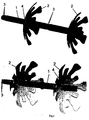
- FIG.1 One possible form of performance of borehole plugging device from different points of views in a volume is shown at Fig.1 .
- Tamping is a process of filling with inert materials of the part of charge cavity; tamping also means inert material used for isolation of explosive charge, reduction of fragment spray radius. Tamping is used for "confining" of detonation products, increase of blast efficiency.
- Borehole plugging device according to the claimed solution represents the replacement of the now existing technology of borehole filling with tamping.
- a borehole plugging device (see. Fig.1 ) constructionally consists of three elements: rod I and at least two dome-shaped elements 2, one of which is fixed at rod from one end and the other end of the rod. Cross section of the rod is cruciform one. This solution permits structure to have required strength and simultaneously use less amount of material for rod fabrication. Thus structure weight is reduced and its production is facilitated.
- Serrations 3 in the area of upper and lower connections of dome-shaped elements can be located at rod 1 for fixation of dome-shaped elements 2.
- dome-shaped elements 2 can contain protrusions 4 by which they are retained (see Fig.2 ) for fixation of dome-shaped elements 2 at the rod 1 .
- the rod 1 of borehole plugging device can be configured to install from two to four dome-shaped elements 2.
- the rod structure also permits to use borehole plugging device as a unit at diameter wide range. Because rock mass opencast fragmentation depends upon numerous factors such as geology, used explosives, development project, used boring equipment different diameter boreholes are bored. Borehole plugging device operating diameters are related to the borehole diameters and are within 65 - 270 mm range. Structure rod is not changed but blades are installed at the rod relative to borehole diameter.
- dome-shaped slotted elements are installed at the rod.
- These slots can be made as blades including those that are symmetrical relative to central axis. If blades are made with different length and with location of each long blade between short ones, slots of borehole plugging device structure at putting to borehole provide availability of design features shown at example of Fig.3 - tamping of borehole plugging device in a borehole.
- Large contact 7 passes via the large blade and small contact 8 goes via small blade.
- Discharge channel 6 via which the explosion wave coming from denotation means channel 5 put in the borehole exits is located in gapping between blades.
- borehole plugging device structure provides channels for detonation means 5, and this solution excludes damage of detonation means (detonation cord, non-electric detonation system) at propagation of structure in a borehole.
- Discharge channel 6 is designed for initial pressure releasing (piston effect). In case of charging of a borehole with excess water pressure discharge channels pass water but explosive remains in borehole charge cavity.
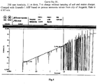
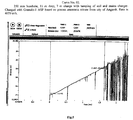
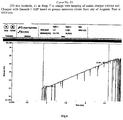
- Fig.4 - Fig.6 show results of measurements at testing of borehole plugging device. They show that detonation rate in trial boreholes is practically the same but insignificant detonation delay in boreholes with use of borehole plugging device is tracked.
Landscapes
- Life Sciences & Earth Sciences (AREA)
- General Life Sciences & Earth Sciences (AREA)
- Engineering & Computer Science (AREA)
- General Engineering & Computer Science (AREA)
- Mining & Mineral Resources (AREA)
- Geology (AREA)
- Fluid Mechanics (AREA)
- Environmental & Geological Engineering (AREA)
- Physics & Mathematics (AREA)
- Geochemistry & Mineralogy (AREA)
- Earth Drilling (AREA)
- Drilling And Exploitation, And Mining Machines And Methods (AREA)
- Investigation Of Foundation Soil And Reinforcement Of Foundation Soil By Compacting Or Drainage (AREA)
- Geophysics And Detection Of Objects (AREA)
Abstract
Description
- The invention relates to the field of drilling and blasting operations and more particularly to confining gaseous explosion products in a charge cavity and can be used in rock blasting using borehole charges.
- Borehole tampings made from rock fines etc. increasing action time of explosion expandable gaseous products at breakable rock mass (Kutuzov B.N. Blasting Operations. M., Nedra, 1988, p.223) are known in the art.
- Tamping for large diameter boreholes (
RF patent No 2122178 D 1/20, 1998), representing a cylinder with internal cavity having semi-sphere shape mating with flattened cone and which fabrication material comprises alkaline-earth metal salt (prototype) is known in the art. Tamping is made of a HP polyethylene as plasticizer. - The disadvantage of this structure is that product has relatively rigid outer surface. The presence of different drilling-out factor and borehole internal surface cleanness of different rocks results in difficulties at tamping installation inside of a borehole. Moreover at tamping diameter increase quantity of material consumed for single product fabrication is increased in many times and this results in significant production cost increase and the existing forming and casting methods do not allow producing large batches of these products with good quality and quickly.
- The closest analogous solution is borehole tamping (Patent
RU2229684
thin-walled funnel the walls of which have the same thickness as cylinder walls and made of the same material and space between funnel and cylinder is filled with inert material. - The prototype provides increase of efficiency and reduction of production costs of blasting operation with borehole method by confining of detonation products in charge cavity till rock mass complete destruction.
- The technical problem of the known technical solutions is the structure complexity, transportation and storage difficulties due to the impossibility to disassemble to compact dimensions, tamping relatively high weight, insufficiently high efficiency of borehole charge operation.
- The object of invention is to attend the specified difficulties by replacement of now existing technology of borehole filling with tamping to borehole plugging device.
- The technical result of this invention is: reducing the specific charge of explosive per cubic meter of blasted rock mass, increasing the fragmentation of the rock mass, making it possible for explosive to be loaded into and work effectively in a borehole with excess water pressure (flooded boreholes), providing ease of use and structural simplicity, providing ease of transportation and storage since device can be dismantled to compact dimensions and reducing the weight of the structure.
- Further technical result is the possibility of using devices of a single type in boreholes of different lengths and types (flooded or non-flooded), thus making it possible for the claimed device to be used as a universal device for all types of boreholes.
- The specified technical result is achieved due to the fact that the claimed borehole plugging device made of a pliable polymer material and having elements with a shape, the outside diameter of which is commensurate with the diameter of a borehole, and an axial internal cavity, is characterized in that it consists of a rod with a cruciform cross section, having identical dome-shaped, slotted elements fixable mounted thereon from each end.
- Preferably dome-shaped elements comprise protrusions that are fixed at serrations made at the rod with stopper. Preferably, dome-shaped elements are made in the form of blades. Preferably blades are made with different length with location of each long blade between short ones.
- Preferably 2-4 dome-shaped elements are fixed at the rod. Preferably dome-shaped elements are made with symmetrical position of slots.
- One possible form of performance of borehole plugging device from different points of views in a volume is shown at
Fig.1 . -
Fig.2 shows example of principle of attaching of dome-shaping element at the rod. -
Fig.3 shows example of placement of borehole plugging device in a borehole. -
Fig.4 - Fig.6 show curves of results of charge denotation experiments using borehole plugging device. - At drawings: 1 - rod, 2 - dome-shaped element, 3 - rod serration, 4 - dome-shaped element protrusion for fixation at a serration, 5 - channel for initiation means, 6 - discharge channel, 7 - large contact, 8 - small contact.
- Tamping is a process of filling with inert materials of the part of charge cavity; tamping also means inert material used for isolation of explosive charge, reduction of fragment spray radius. Tamping is used for "confining" of detonation products, increase of blast efficiency. Borehole plugging device according to the claimed solution represents the replacement of the now existing technology of borehole filling with tamping. A borehole plugging device (see.
Fig.1 ) constructionally consists of three elements: rod I and at least two dome-shaped elements 2, one
of which is fixed at rod from one end and the other end of the rod. Cross section of the rod is cruciform one. This solution permits structure to have required strength and simultaneously use less amount of material for rod fabrication. Thus structure weight is reduced and its production is facilitated. - Serrations 3 (serrate insections) in the area of upper and lower connections of dome-shaped elements can be located at
rod 1 for fixation of dome-shaped elements 2. At theseserrations 3 dome-shaped elements 2 can containprotrusions 4 by which they are retained (seeFig.2 ) for fixation of dome-shaped elements 2 at therod 1 . - The
rod 1 of borehole plugging device can be configured to install from two to four dome-shaped elements 2. The rod structure also permits to use borehole plugging device as a unit at diameter wide range. Because rock mass opencast fragmentation depends upon numerous factors such as geology, used explosives, development project, used boring equipment different diameter boreholes are bored. Borehole plugging device operating diameters are related to the borehole diameters and are within 65 - 270 mm range. Structure rod is not changed but blades are installed at the rod relative to borehole diameter. - Under the conditions of flooded borehole or if borehole length exceeds 15 m 3-4 dome-shaped slotted elements are installed at the rod. These slots can be made as blades including those that are symmetrical relative to central axis. If blades are made with different length and with location of each long blade between short ones, slots of borehole plugging device structure at putting to borehole provide availability of design features shown at example of
Fig.3 - tamping of borehole plugging device in a borehole.Large contact 7 passes via the large blade and small contact 8 goes via small blade.Discharge channel 6 via which the explosion wave coming from denotation meanschannel 5 put in the borehole exits is located in gapping between blades. - For instance slots as blades of borehole plugging device are designed for direct contact with borehole walls, in this structure the diameter range is within 130 - 170 mm. Small contacts 8 ensure optimal attack and resistance angle at diameter from 130 to 150 mm.
Large contacts 7 ensure optimal attack and resistance angle from 150 to 170 mm. Borehole plugging device structure provides channels for detonation means 5, and this solution excludes damage of detonation means (detonation cord, non-electric detonation system) at propagation of structure in a borehole. -
Discharge channel 6 is designed for initial pressure releasing (piston effect). In case of charging of a borehole with excess water pressure discharge channels pass water but explosive remains in borehole charge cavity. - In the process of industrial trials at mine industry enterprises the borehole plugging device used in borehole charge as tamping has shown the following results:
- reduction of specific charge of explosive per cubic meter of blasted rock mass;
- increase of the fragmentation of the rock mass;
- making it possible for explosive to be loaded into and work effectively in a borehole with excess water pressure (flooded boreholes).
- ease of use, transportation and storage since the device can be dismantled to compact dimensions;
- reduction of the weight of structure.
-
Fig.4 - Fig.6 show results of measurements at testing of borehole plugging device. They show that detonation rate in trial boreholes is practically the same but insignificant detonation delay in boreholes with use of borehole plugging device is tracked.
Claims (6)
- Borehole plugging device made of a pliable polymer material and having elements with shape, the outside diameter of which is commensurate with the diameter of a borehole, and axial internal cavity, is characterized in that it consists of a rod with a cruciform cross section, having identical dome-shaped, slotted elements fixably mounted thereon from each end.
- The borehole plugging device as recited in claim 1, is characterized in that dome-shaped elements comprise protrusions that are fixed at serrations made at the rod with stopper.
- The borehole plugging device as recited in claim 1, is characterized in that, dome-shaped elements are made in the form of blades.
- The borehole plugging device as recited in claim 3, is characterized in that blades are made of different length with different length with location of each long blade between short ones.
- The borehole plugging device as recited in claim 1, is characterized in that 2-4 dome-shaped elements are fixed at the rod.
- The borehole plugging device as recited in claims 1-5, is characterized in that dome-shaped elements are made with symmetrical position of slots.
Applications Claiming Priority (2)
| Application Number | Priority Date | Filing Date | Title |
|---|---|---|---|
| RU2017104486A RU2649201C1 (en) | 2017-02-13 | 2017-02-13 | Downhole blocking device |
| PCT/RU2017/000951 WO2018147763A1 (en) | 2017-02-13 | 2017-12-19 | Borehole plugging device |
Publications (2)
| Publication Number | Publication Date |
|---|---|
| EP3628961A1 true EP3628961A1 (en) | 2020-04-01 |
| EP3628961A4 EP3628961A4 (en) | 2021-03-31 |
Family
ID=61867045
Family Applications (1)
| Application Number | Title | Priority Date | Filing Date |
|---|---|---|---|
| EP17895649.6A Withdrawn EP3628961A4 (en) | 2017-02-13 | 2017-12-19 | HOLE PLUG DEVICE |
Country Status (5)
| Country | Link |
|---|---|
| US (1) | US11976913B2 (en) |
| EP (1) | EP3628961A4 (en) |
| AU (1) | AU2017398371B2 (en) |
| RU (1) | RU2649201C1 (en) |
| WO (1) | WO2018147763A1 (en) |
Families Citing this family (5)
| Publication number | Priority date | Publication date | Assignee | Title |
|---|---|---|---|---|
| CN109539918A (en) * | 2018-12-24 | 2019-03-29 | 卢光亮 | A kind of borehole tamponade device |
| RU2732373C1 (en) * | 2020-06-02 | 2020-09-16 | Общество с ограниченной ответственностью "Кузбасспецзатвор" (ООО "Кузбасспецзатвор") | Device for creation of air gaps and elimination of re-drilling in blasting wells |
| CN112629348B (en) * | 2020-12-24 | 2024-07-02 | 中国电建集团成都勘测设计研究院有限公司 | Blast hole blocking device for blasting construction |
| CN114412408A (en) * | 2022-01-06 | 2022-04-29 | 中国地质科学院探矿工艺研究所 | Water burst blocking device in drilling hole for horizontal rope coring |
| CN119779106B (en) * | 2024-12-30 | 2026-03-24 | 南昌大学 | A borehole plugging device and its usage method |
Family Cites Families (14)
| Publication number | Priority date | Publication date | Assignee | Title |
|---|---|---|---|---|
| US2129439A (en) * | 1934-12-18 | 1938-09-06 | Cardox Corp | Anchoring means |
| US2449645A (en) * | 1947-02-13 | 1948-09-21 | Du Pont | Blasting plug |
| US2916995A (en) * | 1956-05-17 | 1959-12-15 | Du Pont | Tamping plug |
| NL264205A (en) * | 1960-08-11 | |||
| AU462018B2 (en) * | 1970-09-21 | 1975-06-12 | Ici Australia Limited | Improvements in and relating to resilient stemming devices |
| US5841060A (en) * | 1995-10-24 | 1998-11-24 | Skaggs; Roger Dean | Blast plug |
| RU2122178C1 (en) | 1997-04-10 | 1998-11-20 | Санкт-Петербургский государственный горный институт им.Г.В.Плеханова (технический университет) | Stemming for big wells |
| RU2229684C1 (en) | 2002-11-20 | 2004-05-27 | Санкт-Петербургский государственный горный институт им. Г.В. Плеханова (Технический университет) | Deep-hole stemming |
| AU2004225449A1 (en) * | 2003-04-03 | 2004-10-14 | Robert John Stockl | Explosion container |
| US8413583B2 (en) * | 2010-07-23 | 2013-04-09 | Samuel T. Sloan | Hole covering and locator |
| MX372758B (en) * | 2014-01-13 | 2020-06-29 | Rise Mining Dev Pty Ltd | IMPROVED O-RING DRILLING PLUG. |
| RU147959U1 (en) * | 2014-07-08 | 2014-11-20 | Алексей Алмазович Галимьянов | DEVICE FOR CREATING AIR CHAMBERS IN WELL CHARGES |
| CN104792238A (en) * | 2015-05-08 | 2015-07-22 | 威海埃姆提爱矿山设备有限公司 | Fan-shaped blast hole positioning device |
| US9816794B1 (en) * | 2017-01-17 | 2017-11-14 | William Jordan Rice | Blasting plug |
-
2017
- 2017-02-13 RU RU2017104486A patent/RU2649201C1/en active
- 2017-12-19 AU AU2017398371A patent/AU2017398371B2/en active Active
- 2017-12-19 WO PCT/RU2017/000951 patent/WO2018147763A1/en not_active Ceased
- 2017-12-19 US US16/484,671 patent/US11976913B2/en active Active
- 2017-12-19 EP EP17895649.6A patent/EP3628961A4/en not_active Withdrawn
Also Published As
| Publication number | Publication date |
|---|---|
| RU2649201C1 (en) | 2018-03-30 |
| AU2017398371B2 (en) | 2024-02-15 |
| EP3628961A4 (en) | 2021-03-31 |
| AU2017398371A1 (en) | 2019-09-26 |
| US20200132424A1 (en) | 2020-04-30 |
| WO2018147763A1 (en) | 2018-08-16 |
| WO2018147763A9 (en) | 2018-10-11 |
| US11976913B2 (en) | 2024-05-07 |
Similar Documents
| Publication | Publication Date | Title |
|---|---|---|
| EP3628961A1 (en) | Borehole plugging device | |
| US10364387B2 (en) | Subterranean formation shock fracturing charge delivery system | |
| FI111871B (en) | Device and method of breaking material | |
| CN116294871A (en) | Blasting method using jet unit charged in blast hole | |
| US9010246B2 (en) | Surface blasting product | |
| CN110986713A (en) | Large-diameter ultra-deep hole radiation energy accumulation loosening pre-splitting blasting device and filling method | |
| EP2153164B1 (en) | A device, charging unit and method of filling a borehole with an explosive material | |
| CN106767185A (en) | The Multi-point Initiation Device and its installation and application method of a kind of lifting hole bottom detonation pressure | |
| CN106839909B (en) | Reduce the multidirectional collision cumulative multipoint priming method of Long-hole Bench Blasting foundation | |
| RU2524829C2 (en) | Charge | |
| KR100534148B1 (en) | a Fracture controlled blasting method using split tube and air decking | |
| CN116793172A (en) | Roadway tunneling energy-gathering hydraulic smooth blasting peripheral hole charging method | |
| KR102288035B1 (en) | Rock blasting method using a connected paper pipe | |
| CN104713432A (en) | Blasting method employing detonation wave energy collection | |
| CN110243244A (en) | It is a kind of based on Detonation waveform modulation circumferential slit without cavity liner air gap CUMULATIVE BLASTING loading method | |
| CN209991885U (en) | Novel nine-hole cut structure | |
| CN107726936B (en) | Self-closing spiral energy-gathering joint cutter | |
| CN205241557U (en) | Scene loads in mixture static sensitization ware of emulsion explosive truck in pit | |
| KR102398623B1 (en) | Rock blasting method using paraffin and paper pipe | |
| RU132178U1 (en) | EXPLOSIVE WELL CHARGING WITH GAS-DYNAMIC DETONATION STABILIZER | |
| RU176154U1 (en) | BOTTOM LOCKING DEVICE | |
| CN111023928A (en) | Method for improving ore dropping efficiency without bottom pillar | |
| EP3816394B1 (en) | A method and a drill bit for sealing a blasthole wall | |
| CN110530218B (en) | A method for removing angle steel by non-punching blasting | |
| RU2280236C1 (en) | Combination explosive charge |
Legal Events
| Date | Code | Title | Description |
|---|---|---|---|
| STAA | Information on the status of an ep patent application or granted ep patent |
Free format text: STATUS: THE INTERNATIONAL PUBLICATION HAS BEEN MADE |
|
| PUAI | Public reference made under article 153(3) epc to a published international application that has entered the european phase |
Free format text: ORIGINAL CODE: 0009012 |
|
| STAA | Information on the status of an ep patent application or granted ep patent |
Free format text: STATUS: REQUEST FOR EXAMINATION WAS MADE |
|
| 17P | Request for examination filed |
Effective date: 20200220 |
|
| AK | Designated contracting states |
Kind code of ref document: A1 Designated state(s): AL AT BE BG CH CY CZ DE DK EE ES FI FR GB GR HR HU IE IS IT LI LT LU LV MC MK MT NL NO PL PT RO RS SE SI SK SM TR |
|
| AX | Request for extension of the european patent |
Extension state: BA ME |
|
| DAV | Request for validation of the european patent (deleted) | ||
| DAX | Request for extension of the european patent (deleted) | ||
| RAP1 | Party data changed (applicant data changed or rights of an application transferred) |
Owner name: MINING TECHNOLOGIES RT JSC |
|
| RIN1 | Information on inventor provided before grant (corrected) |
Inventor name: SHUSTOV, ALEKSEJJ NIKOLAEVICH |
|
| RIN1 | Information on inventor provided before grant (corrected) |
Inventor name: SHUSTOV, ALEKSEJJ NIKOLAEVICH |
|
| A4 | Supplementary search report drawn up and despatched |
Effective date: 20210303 |
|
| RIC1 | Information provided on ipc code assigned before grant |
Ipc: F42D 1/08 20060101AFI20210225BHEP Ipc: F42D 1/18 20060101ALI20210225BHEP |
|
| STAA | Information on the status of an ep patent application or granted ep patent |
Free format text: STATUS: THE APPLICATION IS DEEMED TO BE WITHDRAWN |
|
| 18D | Application deemed to be withdrawn |
Effective date: 20240702 |