EP3628954B1 - Heat exchanger with tank of phase-change material and associated manufacturing method - Google Patents
Heat exchanger with tank of phase-change material and associated manufacturing method Download PDFInfo
- Publication number
- EP3628954B1 EP3628954B1 EP19196636.5A EP19196636A EP3628954B1 EP 3628954 B1 EP3628954 B1 EP 3628954B1 EP 19196636 A EP19196636 A EP 19196636A EP 3628954 B1 EP3628954 B1 EP 3628954B1
- Authority
- EP
- European Patent Office
- Prior art keywords
- filling
- reservoir
- external surface
- heat exchanger
- internal surface
- Prior art date
- Legal status (The legal status is an assumption and is not a legal conclusion. Google has not performed a legal analysis and makes no representation as to the accuracy of the status listed.)
- Active
Links
- 239000012782 phase change material Substances 0.000 title claims description 31
- 238000004519 manufacturing process Methods 0.000 title claims description 15
- 239000013529 heat transfer fluid Substances 0.000 claims description 21
- 238000000034 method Methods 0.000 claims description 14
- 238000003466 welding Methods 0.000 claims description 11
- 238000005219 brazing Methods 0.000 claims description 9
- 238000005520 cutting process Methods 0.000 claims description 5
- 239000000945 filler Substances 0.000 description 19
- 125000006850 spacer group Chemical group 0.000 description 10
- 230000015572 biosynthetic process Effects 0.000 description 8
- 238000007789 sealing Methods 0.000 description 8
- 238000004378 air conditioning Methods 0.000 description 7
- 239000012530 fluid Substances 0.000 description 2
- 238000010438 heat treatment Methods 0.000 description 2
- 239000000463 material Substances 0.000 description 2
- 239000003507 refrigerant Substances 0.000 description 2
- 238000009423 ventilation Methods 0.000 description 2
- 229910000838 Al alloy Inorganic materials 0.000 description 1
- 239000002826 coolant Substances 0.000 description 1
- 238000001816 cooling Methods 0.000 description 1
- 230000010354 integration Effects 0.000 description 1
- 238000005304 joining Methods 0.000 description 1
- 229910052751 metal Inorganic materials 0.000 description 1
- 239000002184 metal Substances 0.000 description 1
- 238000005476 soldering Methods 0.000 description 1
- 238000012795 verification Methods 0.000 description 1
- XLYOFNOQVPJJNP-UHFFFAOYSA-N water Substances O XLYOFNOQVPJJNP-UHFFFAOYSA-N 0.000 description 1
Images


Classifications
-
- F—MECHANICAL ENGINEERING; LIGHTING; HEATING; WEAPONS; BLASTING
- F28—HEAT EXCHANGE IN GENERAL
- F28D—HEAT-EXCHANGE APPARATUS, NOT PROVIDED FOR IN ANOTHER SUBCLASS, IN WHICH THE HEAT-EXCHANGE MEDIA DO NOT COME INTO DIRECT CONTACT
- F28D1/00—Heat-exchange apparatus having stationary conduit assemblies for one heat-exchange medium only, the media being in contact with different sides of the conduit wall, in which the other heat-exchange medium is a large body of fluid, e.g. domestic or motor car radiators
- F28D1/02—Heat-exchange apparatus having stationary conduit assemblies for one heat-exchange medium only, the media being in contact with different sides of the conduit wall, in which the other heat-exchange medium is a large body of fluid, e.g. domestic or motor car radiators with heat-exchange conduits immersed in the body of fluid
- F28D1/04—Heat-exchange apparatus having stationary conduit assemblies for one heat-exchange medium only, the media being in contact with different sides of the conduit wall, in which the other heat-exchange medium is a large body of fluid, e.g. domestic or motor car radiators with heat-exchange conduits immersed in the body of fluid with tubular conduits
- F28D1/053—Heat-exchange apparatus having stationary conduit assemblies for one heat-exchange medium only, the media being in contact with different sides of the conduit wall, in which the other heat-exchange medium is a large body of fluid, e.g. domestic or motor car radiators with heat-exchange conduits immersed in the body of fluid with tubular conduits the conduits being straight
- F28D1/0535—Heat-exchange apparatus having stationary conduit assemblies for one heat-exchange medium only, the media being in contact with different sides of the conduit wall, in which the other heat-exchange medium is a large body of fluid, e.g. domestic or motor car radiators with heat-exchange conduits immersed in the body of fluid with tubular conduits the conduits being straight the conduits having a non-circular cross-section
- F28D1/05358—Assemblies of conduits connected side by side or with individual headers, e.g. section type radiators
-
- F—MECHANICAL ENGINEERING; LIGHTING; HEATING; WEAPONS; BLASTING
- F28—HEAT EXCHANGE IN GENERAL
- F28D—HEAT-EXCHANGE APPARATUS, NOT PROVIDED FOR IN ANOTHER SUBCLASS, IN WHICH THE HEAT-EXCHANGE MEDIA DO NOT COME INTO DIRECT CONTACT
- F28D1/00—Heat-exchange apparatus having stationary conduit assemblies for one heat-exchange medium only, the media being in contact with different sides of the conduit wall, in which the other heat-exchange medium is a large body of fluid, e.g. domestic or motor car radiators
- F28D1/02—Heat-exchange apparatus having stationary conduit assemblies for one heat-exchange medium only, the media being in contact with different sides of the conduit wall, in which the other heat-exchange medium is a large body of fluid, e.g. domestic or motor car radiators with heat-exchange conduits immersed in the body of fluid
- F28D1/03—Heat-exchange apparatus having stationary conduit assemblies for one heat-exchange medium only, the media being in contact with different sides of the conduit wall, in which the other heat-exchange medium is a large body of fluid, e.g. domestic or motor car radiators with heat-exchange conduits immersed in the body of fluid with plate-like or laminated conduits
- F28D1/0308—Heat-exchange apparatus having stationary conduit assemblies for one heat-exchange medium only, the media being in contact with different sides of the conduit wall, in which the other heat-exchange medium is a large body of fluid, e.g. domestic or motor car radiators with heat-exchange conduits immersed in the body of fluid with plate-like or laminated conduits the conduits being formed by paired plates touching each other
- F28D1/0325—Heat-exchange apparatus having stationary conduit assemblies for one heat-exchange medium only, the media being in contact with different sides of the conduit wall, in which the other heat-exchange medium is a large body of fluid, e.g. domestic or motor car radiators with heat-exchange conduits immersed in the body of fluid with plate-like or laminated conduits the conduits being formed by paired plates touching each other the plates having lateral openings therein for circulation of the heat-exchange medium from one conduit to another
- F28D1/0333—Heat-exchange apparatus having stationary conduit assemblies for one heat-exchange medium only, the media being in contact with different sides of the conduit wall, in which the other heat-exchange medium is a large body of fluid, e.g. domestic or motor car radiators with heat-exchange conduits immersed in the body of fluid with plate-like or laminated conduits the conduits being formed by paired plates touching each other the plates having lateral openings therein for circulation of the heat-exchange medium from one conduit to another the plates having integrated connecting members
-
- F—MECHANICAL ENGINEERING; LIGHTING; HEATING; WEAPONS; BLASTING
- F28—HEAT EXCHANGE IN GENERAL
- F28D—HEAT-EXCHANGE APPARATUS, NOT PROVIDED FOR IN ANOTHER SUBCLASS, IN WHICH THE HEAT-EXCHANGE MEDIA DO NOT COME INTO DIRECT CONTACT
- F28D20/00—Heat storage plants or apparatus in general; Regenerative heat-exchange apparatus not covered by groups F28D17/00 or F28D19/00
- F28D20/02—Heat storage plants or apparatus in general; Regenerative heat-exchange apparatus not covered by groups F28D17/00 or F28D19/00 using latent heat
-
- F—MECHANICAL ENGINEERING; LIGHTING; HEATING; WEAPONS; BLASTING
- F28—HEAT EXCHANGE IN GENERAL
- F28D—HEAT-EXCHANGE APPARATUS, NOT PROVIDED FOR IN ANOTHER SUBCLASS, IN WHICH THE HEAT-EXCHANGE MEDIA DO NOT COME INTO DIRECT CONTACT
- F28D20/00—Heat storage plants or apparatus in general; Regenerative heat-exchange apparatus not covered by groups F28D17/00 or F28D19/00
- F28D2020/0004—Particular heat storage apparatus
- F28D2020/0013—Particular heat storage apparatus the heat storage material being enclosed in elements attached to or integral with heat exchange conduits
-
- F—MECHANICAL ENGINEERING; LIGHTING; HEATING; WEAPONS; BLASTING
- F28—HEAT EXCHANGE IN GENERAL
- F28D—HEAT-EXCHANGE APPARATUS, NOT PROVIDED FOR IN ANOTHER SUBCLASS, IN WHICH THE HEAT-EXCHANGE MEDIA DO NOT COME INTO DIRECT CONTACT
- F28D21/00—Heat-exchange apparatus not covered by any of the groups F28D1/00 - F28D20/00
- F28D2021/0019—Other heat exchangers for particular applications; Heat exchange systems not otherwise provided for
- F28D2021/008—Other heat exchangers for particular applications; Heat exchange systems not otherwise provided for for vehicles
- F28D2021/0085—Evaporators
-
- Y—GENERAL TAGGING OF NEW TECHNOLOGICAL DEVELOPMENTS; GENERAL TAGGING OF CROSS-SECTIONAL TECHNOLOGIES SPANNING OVER SEVERAL SECTIONS OF THE IPC; TECHNICAL SUBJECTS COVERED BY FORMER USPC CROSS-REFERENCE ART COLLECTIONS [XRACs] AND DIGESTS
- Y02—TECHNOLOGIES OR APPLICATIONS FOR MITIGATION OR ADAPTATION AGAINST CLIMATE CHANGE
- Y02E—REDUCTION OF GREENHOUSE GAS [GHG] EMISSIONS, RELATED TO ENERGY GENERATION, TRANSMISSION OR DISTRIBUTION
- Y02E60/00—Enabling technologies; Technologies with a potential or indirect contribution to GHG emissions mitigation
- Y02E60/14—Thermal energy storage
Definitions
- the present invention relates to heat exchangers and more specifically to heat exchangers comprising a phase change material, in particular in the field of thermal management within a motor vehicle.
- Such an exchanger is known from FR 3 048 495 disclosing the preamble of claim 1.
- the present invention also relates to a method of manufacturing such a phase change material heat exchanger.
- these air conditioning devices implement a heat exchanger, for example an evaporator, such as that shown in figure 1 .
- Such a heat exchanger 1 comprises a bundle of tubes 10 formed of a stack of tubes 10. Spacers 11 are generally placed between two consecutive tubes 10. This bundle of tubes 10 allows a heat exchange between a first heat transfer fluid circulating in the tubes 10 and a second heat transfer fluid, generally a flow of air passing between the tubes (and more precisely through the spacers).
- the heat exchanger 1 implements one or more tanks of phase change material 12 capable of storing cold when the engine of the motor vehicle is running in order to then restore it to the flow of air passing through the heat exchanger 1 so as to cool it, for a limited time, when the vehicle engine is stopped.
- a heat exchanger 1 of this type comprises at least one reservoir plate 120 which, after brazing with an outer face of a tube 10 of the heat exchange bundle, forms a reservoir 12 filled with phase change material.
- the tube 10 is obtained by brazing two tube plates 10A between which is placed an internal spacer 103 ( picture 2 ).
- Reservoir 12 of phase change material is thus in thermal contact with an outer face of tube 10, the reservoir being delimited by reservoir plate 120 and an opposite surface corresponding to an outer face of tube 10.
- Each reservoir 12 of phase change material comprises its own filling tube allowing a phase change material to be injected inside the reservoir 12.
- a filling member is added to the reservoir 12 in order to allow it to be filled with phase change material.
- This filler may in particular be a conduit comprising one or more orifices which are placed and fixed opposite openings arranged on the tank plate 120.
- Such fillers are not necessarily suitable because they represent a separate part which has a production cost and whose placement may be faulty causing difficulties in filling the tank.
- One of the aims of the present invention is to remedy at least partially the drawbacks of the prior art and to propose a phase change material heat exchanger with an improved filler member as well as its method of manufacture.
- the present invention therefore relates to a heat exchanger comprising a bundle of tubes inside which a first heat transfer fluid is intended to circulate and between which a second heat transfer fluid is intended to circulate, said bundle of tubes comprising at least one reservoir of material with phase change, said reservoir being delimited by at least one reservoir plate comprising a filling member,
- the filling member comprising a stamped external surface integral with the reservoir plate and folded over an internal surface also integral with said reservoir plate so as to form a filling channel, said internal surface comprising at least one filling orifice opening into said reservoir and said external surface covering said at least one filling orifice.
- the reservoir plate has a substantially rectangular shape comprising two long sides and two short sides and the outer surface of the filler member is folded over the inner surface around a folding axis arranged on a said short sides of the reservoir plate.
- the outer surface of the filler member is fixed to the inner surface (140a) by brazing.
- the reservoir comprises a boss and the external surface a stamping, the height of the stamping of the external surface being less than or equal to the height of said boss.
- the filling member comprises a closure zone formed by a laterally projecting part of the external surface and a laterally projecting part of the internal surface joined to each other in a sealed manner.
- the reservoir plate has a substantially rectangular shape comprising two long sides and two short sides and the closure zone is arranged on one of said long sides.
- the closure zone extends over a length of at most ten millimeters.
- the step of closing the filling channel is performed by welding the outer surface to the inner surface.
- the welding is an ultrasonic welding.
- the location of the closure zone is chosen so that once said cutting step has been performed, the closure zone extends over a length of at most ten millimeters.
- first element or second element as well as first parameter and second parameter or even first criterion and second criterion, etc.
- it is a simple indexing to differentiate and name elements or parameters or similar but not identical criteria.
- This indexing does not imply a priority of one element, parameter or criterion with respect to another and it is easy to interchange such denominations without departing from the scope of the present description.
- This indexation does not imply an order in time either, for example to assess such and such a criterion.
- a heat exchanger 1 intended to be placed in a heating, ventilation and air conditioning device as an evaporator within an air conditioning circuit as an evaporator.
- This evaporator is in particular intended for the heat exchange between a flow of air and a refrigerant fluid circulating in the air conditioning circuit of the motor vehicle.
- the invention also covers a condenser, a radiator or any other heat exchanger, whatever the heat transfer fluid which passes through it.
- the heat exchanger 1 conventionally comprises a bundle of tubes 10 formed by a parallel stack of tubes 10 and outer spacers 11 in a longitudinal stacking direction (visible on the picture 3 ).
- first heat transfer fluid in particular the refrigerant of the air conditioning circuit in the case of an evaporator.
- This first heat transfer fluid circulates between the ends 13 of the tubes 10. These ends 13 can form collectors or water boxes as illustrated in the picture 3 .
- Spacers 11 which may or may not have louvres, are placed between two consecutive tubes 10 and make it possible to increase the heat exchange surface between a second heat transfer fluid, for example an air flow, passing between the tubes 10 and the first coolant fluid circulating in the tubes 10.
- a second heat transfer fluid for example an air flow
- the tube 10 on which a reservoir plate 120 is assembled comprises two plates 10A which are stamped and brazed to one another and between which an internal disruptor 103 may be placed in the form of a corrugated sheet.
- the plates 10A are stamped and assembled together in a sealed manner so as to form, after assembly, two adjacent ducts 513, 514, inside which the first heat transfer fluid circulates.
- the tank plate 120 is attached to another tube 10.
- the tank 12 is formed on the one hand by a tank plate 120 and on the other hand by an opposite surface, which here consists of an outer face of the tube 10 (in this case the face external plate 10A).
- phase change material stored in the reservoir 12 is in direct contact with the outer face of the tube 10, which facilitates and improves heat exchange between the first heat transfer fluid circulating in the tube 10 and the phase change material. stored in tank 12.
- the reservoir plate 120 may in particular have a plurality of bosses which are distributed over its entire surface (these bosses are also visible on the figures 4 to 9 ).
- the bosses of the reservoir plate 120 coupled to a first tube 10 are tangent or flush with the outer face of an adjacent second tube 10 (not shown). Passages are thus delimited outside the reservoir 12 of phase-change material so that the second heat transfer fluid can circulate between the reservoir plate 120 and the external face of the second tube 10 adjacent to the bundle of tube 10 . This makes it possible to optimize the heat exchanges between the first heat transfer fluid and the second heat transfer fluid.
- phase change material As shown in picture 3 , one or more spacers 11 are substituted by a reservoir 12 of phase change material.
- this phase-change material is capable of storing cold when the engine of the motor vehicle is running in order to then release it, for a limited period, to the air passing through the evaporator when the engine of the vehicle is stationary.
- the heat exchanger 1 shown in the picture 3 more particularly comprises ten reservoirs 12 of phase change material.
- Each tank 12 comprises a flattened filling member 14 taking the form of a flat tube and projecting from an external face 1A of the tube bundle 10.
- These filling members 14 can in particular be aligned with each other as shown in picture 3 .
- the filling with phase change material is carried out using a filling member 14 specific to each reservoir 12 of phase change material.
- the tube plates 10, the reservoir plates 120, the outer spacers and the fillers 14 are preferably made of metal, for example an aluminum alloy or the like. This makes it possible to fix them to each other during the same soldering step.
- the figures 5 to 9 show different stages in the formation of a filler 14.
- the figure 5 shows more precisely a reservoir plate 120 before the formation of the filling member 14.
- the reservoir plate 120 comprises a filling zone 140 comprising an internal surface 140a comprising at least one reservoir filling orifice 1201 and a projecting part 141a laterally from the reservoir plate. This at least one filling orifice 1201 opens into the tank 12 in order to allow filling.
- the reservoir plate 120 has two filling orifices 1201.
- the projecting part 141a extends parallel to the general plane defined by the tank plate 120.
- this laterally projecting part 141a extends in a lateral direction so that it protrudes from one of the external faces of the tube bundle 10 as illustrated in the picture 3 .
- the filling zone 140 also comprises an external surface 140b stamped and attached to the internal surface 140b and intended to cover it.
- This external surface 140b can also comprise a protruding part 141b intended to cover the protruding part 141a of the internal surface 140a.
- the filling zone 140 and more particularly the internal 140a and external 140b surfaces, are thus integral with the reservoir plate 12.
- This filling zone filler 140 can in particular be formed by stamping during the manufacture of said reservoir plate 12 and in particular during the formation of the boss.
- the internal 140a and external 140b zones can have a generally rectangular shape and be connected to each other by one of their long sides, as illustrated in the figure 5 . However, it is quite possible to imagine a particular embodiment where the internal 140a and external 140b zones are connected to each other by one of their short sides.
- the reservoir plate 120 may in particular have a substantially rectangular shape comprising two long sides and two short sides.
- the filling zone 140 can in particular be made on one end of the reservoir plate 120 at one of its short sides.
- the internal surface 140a and the external surface 140b can extend perpendicularly to the longitudinal axis of the reservoir plate 120 and their projections 141a, 141b protrude from one of the long sides of the reservoir plate 120.
- the projecting part 141a of the internal surface 140a comprises a filling opening 1410.
- this filling opening 1410 can be made on the projecting part 141b of the external surface 140b.
- the outer surface 140b is folded over the inner surface 140a along a folding axis A corresponding to the connection between these two surfaces.
- the filling member 14 then forms a filling channel connecting the at least one filling orifice 1201 of the tank 12 and the filling opening 1410.
- the internal surface 140a and the external surface 140b are fixed to each other in a sealed manner, for example by brazing.
- the outer surface 140b may include a rim 142b (visible on the figure 5 ) which is pressed against the inner surface 140a and at which the fixing is made.
- the rim 142b completely surrounds the outer surface 140b and delimits a recessed stamping 143b.
- the height of the stamping 143b of the outer surface 140b is preferably less than or equal to the height of the boss of the reservoir plate 120. Thus, when the outer surface 140b covers the inner surface 140a, said outer surface 140b does not exceed the tank plate boss height 120.
- the filler 14 is integral with the tank plate 120. This allows better sealing of the filler and also simplifies the manufacturing process by avoiding the addition of a separate element as a filler. Moreover, it is no longer necessary to match the at least one filling orifice 1201 with a particular orifice of the filling member as is the case in the prior art.
- the filling member 14 thus comprises at this stage an outer surface 140b folded over the inner surface 140a, so as to form a filling channel.
- the internal surface 140a comprises at least one filling orifice 1201.
- the external surface 140b also covers said at least one filling orifice 1201.
- the folding axis A is arranged on one of the short sides of the reservoir plate 120.
- the filler 14 also comprises a projecting part 141 laterally formed by the projecting parts 141a, 141b of the inner 140a and outer surfaces 140b.
- the projecting part 141 extends parallel to the general plane defined by the reservoir plate 120.
- this projecting part 141 extends in a lateral direction so that it protrudes from one of the faces outer tube bundle 10 as shown in figure picture 3 .
- the filling member 14 can extend perpendicularly or parallel to the longitudinal axis of the reservoir plate 12.
- the protruding part 141 can for its part protrude from one of the large ribs or one of the short sides of the reservoir plate 120.
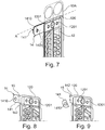
- This protruding part 141 is intended to be removed after the reservoir 12 has been filled, as shown in the figures 8 and 9 .
- a closure zone 15 is produced on the projecting part 141 between the filling opening 1410 and the filling orifice 1201.
- This closure zone 15 can in particular be produced by welding the internal surface 140a with the outer surface 140b, for example by ultrasonic welding. This welding is in particular carried out after crushing in order to bring the internal 140a and external 140b surfaces closer together.
- the portion of the projecting part 141 of the filling member 14 is cut so that only the closure zone 15 projects laterally.
- the projecting part comprising the closure zone 15 extends over a length of at most ten millimeters so as not to protrude excessively from the bundle of tubes 10. This slight protrusion of the filling member 14 facilitates the integration of the heat exchanger 1 in a casing of a heating, ventilation and air conditioning device.
- the closure zone 15 can thus protrude from one of the long sides or from one of the short sides of the reservoir plate 120 depending on how the projecting part 141 was oriented.
- the reservoir 12 of phase change material is not formed of a reservoir plate 120 and an opposite surface formed by an outer face of a tube 10.
- the tank 12 is formed by a first tank plate 120 and an opposite surface, which is here constituted by a second tank plate 120.
- the first tank plate 120 is in contact with a first tube 10 while the second tank plate 120 is in contact with a second tube 10.
- the first and second tank plates 120 are essentially identical and are preferably symmetrical with respect to their joint plane.
- the second tank plate is however not secured to a filling member 14 and therefore does not include a filling orifice 1201.
- the manufacturing process of the phase change material heat exchanger 1 can thus comprise the following steps summarized in the flowchart of the figure 10 .
- the manufacture of an evaporator according to the invention obviously comprises a preliminary step 190 of collecting all of the elements making it up, in particular tube plates 10, internal disruptor 103, spacers 11, first and, if necessary, second tank plates 120. At least one of the reservoir plates 120 comprising a filling zone 140 as described above in the description.
- the filling member 14 is formed during a step 191 by folding the outer surface 140b onto the inner surface 140a so as to form a filling channel connecting the at least one filling orifice 1201 of the reservoir 12 and the filling opening 1410.
- This pre-assembly consists of stacking a plurality of tubes 10 against each other, each tube 10 being made up of the stack of two plates 10A with the case optional interposition of a spacer 11. Some of the spaces between consecutive tubes 10 are filled with a spacer 11 or with a first tank plate 120 comprising a filling member 14 or, where appropriate, a first and a second tank plate 120 joined together. to each other.
- This assembly is kept pre-assembled by means of a tool provided for this purpose which makes it possible to keep the various components of the evaporator 1 slightly compressed against each other.
- This pre-assembled assembly is then introduced into a furnace inside which a brazing step 193 is implemented.
- This brazing step 193 allows the various elements forming the tube bundle 10 to be fixed and also allows the outer surface 140b to be fixed to the inner surface 140a in order to form the filling member 14.
- the method then comprises a step 194 of filling the reservoir(s) 12 with phase change material.
- This step consists in injecting, for example by drawing under vacuum, a phase change material inside each reservoir 12 via the corresponding filling member 14 .
- This material flows into each filler 14 from its filler opening 1410 and flows into the filler channel and then through the filler ports 1201 until it spills into the reservoirs 12.
- Each reservoir 12 is then closed during a step 195 by the implementation of a closure zone 15 at the level of the projecting part 141 of the filling member 14.
- This closure zone 15 allows the filling member 14 to be closed off.
- the internal 140a and external 140b surfaces are joined together over their entire height by welding, in particular by ultrasonic welding. Any other known joining technique can be implemented.
- the invention proposes a flat sealing solution which greatly reduces the risks of leakage of phase change material.
- the method can also then comprise a test step 196 which consists in checking the tightness of the closure zone 15.
- This sealing verification step 196 includes a step of pressurizing or depressurizing the part of the filling chamber located in the first end portion 141 via the filling opening 1410. It is thus possible to guarantee the sealing of the closure of the reservoir 12 of phase change material after filling and sealing of the filling member 14.
- the method finally comprises a step 197 of cutting out the projecting part 141 so that once said projecting part 141 has been cut, only the closure zone 15 projects laterally from the reservoir plate 120.
- the filler 14 is made in one piece with the reservoir plate 14 allows better sealing as well as a simpler manufacturing process.
- the fact also that the manufacturing method does not involve a separate filling element that must be placed in a precise position also makes it possible to reduce the risk of errors during assembly.
Landscapes
- Engineering & Computer Science (AREA)
- Physics & Mathematics (AREA)
- Thermal Sciences (AREA)
- Mechanical Engineering (AREA)
- General Engineering & Computer Science (AREA)
- Heat-Exchange Devices With Radiators And Conduit Assemblies (AREA)
Description
La présente invention concerne les échangeurs de chaleur et plus précisément les échangeurs de chaleur comportant un matériau à changement de phase, notamment dans le domaine de la gestion thermique au sein d'un véhicule automobile. Un tel échangeur est connu de
La présente invention concerne également un procédé de fabrication d'un tel échangeur de chaleur à matériau à changement de phase.The present invention also relates to a method of manufacturing such a phase change material heat exchanger.
Dans les véhicules automobiles, il est connu de mettre en œuvre un dispositif de climatisation permettant de réguler la température de l'habitacle du véhicule.In motor vehicles, it is known to implement an air conditioning device making it possible to regulate the temperature of the passenger compartment of the vehicle.
Plus précisément, ces dispositifs de climatisation mettent en œuvre un échangeur de chaleur, par exemple un évaporateur, tel que celui représenté à la
Un tel échangeur de chaleur 1 comprend un faisceau de tubes 10 formé d'un empilement de tubes 10. Des intercalaires 11 sont généralement placés entre deux tubes 10 consécutifs. Ce faisceau de tubes 10 permet un échange de chaleur entre un premier fluide caloporteur circulant dans les tubes 10 et un deuxième fluide caloporteur, généralement un flux d'air passant entre les tubes (et plus précisément à travers les intercalaires).Such a heat exchanger 1 comprises a bundle of
Pour les véhicules munis d'un système d'arrêt automatique du moteur lors des arrêts courts du véhicule notamment, une fonction a été développée et permet, lorsque le moteur du véhicule est à l'arrêt et n'entraîne plus le compresseur de mise en circulation du fluide caloporteur, de maintenir le refroidissement de l'habitacle du véhicule, améliorant ainsi le confort des passagers du véhicule automobile.For vehicles fitted with an automatic engine shutdown system during short vehicle stops in particular, a function has been developed which allows, when the vehicle engine is stopped and no longer drives the start-up compressor circulation of the heat transfer fluid, to maintain the cooling of the passenger compartment of the vehicle, thus improving the comfort of the passengers of the motor vehicle.
Pour ce faire, l' échangeur de chaleur 1 met en œuvre un ou plusieurs réservoirs de matériau à changement de phase 12 aptes à stocker du froid lorsque le moteur du véhicule automobile est en marche pour ensuite le restituer au flux d'air traversant l' échangeur de chaleur 1 de sorte à le refroidir, pour une durée limitée, lorsque le moteur du véhicule est à l'arrêt.To do this, the heat exchanger 1 implements one or more tanks of
Un échangeur de chaleur 1 de ce type, illustré partiellement sur la
On note que, de façon classique, le tube 10 est obtenu par brasage de deux plaques de tube 10A entre lesquelles est disposé un intercalaire interne 103 (
Le réservoir 12 de matériau à changement de phase est ainsi en contact thermique avec une face externe du tube 10, le réservoir étant délimité par la plaque réservoir 120 et une surface opposée correspondant à une face externe du tube 10.
Chaque réservoir 12 de matériau à changement de phase comprend son propre tube de remplissage permettant d'injecter un matériau à changement de phase à l'intérieur du réservoir 12.Each
En règle générale, il est adjoint au réservoir 12 un organe de remplissage afin de permettre son remplissage en matériau à changement de phase. Cet organe de remplissage peut notamment être un conduit comportant un ou plusieurs orifices que l'on vient placer et fixer en regard d'ouvertures disposées sur la plaque réservoir 120. De tels organes de remplissage ne sont par forcement adaptés car ils représentent une pièce distincte qui a un coût de production et dont le placement peut être défaillant entraînant des difficultés pour le remplissage du réservoir.As a general rule, a filling member is added to the
Un des buts de la présente invention est de remédier au moins partiellement aux inconvénients de l'art antérieur et de proposer un échangeur de chaleur à matériau à changement de phase avec un organe de remplissage amélioré ainsi que son procédé de fabrication.One of the aims of the present invention is to remedy at least partially the drawbacks of the prior art and to propose a phase change material heat exchanger with an improved filler member as well as its method of manufacture.
La présente invention concerne donc un échangeur de chaleur comportant un faisceau de tubes à l'intérieur desquels est destiné à circuler un premier fluide caloporteur et entre lesquels est destiné à circuler un deuxième fluide caloporteur, ledit faisceau de tubes comportant au moins un réservoir de matériau à changement de phase, ledit réservoir étant délimité par au moins une plaque réservoir comportant un organe de remplissage,The present invention therefore relates to a heat exchanger comprising a bundle of tubes inside which a first heat transfer fluid is intended to circulate and between which a second heat transfer fluid is intended to circulate, said bundle of tubes comprising at least one reservoir of material with phase change, said reservoir being delimited by at least one reservoir plate comprising a filling member,
l'organe de remplissage comportant une surface externe emboutie venant de matière avec la plaque réservoir et repliée sur une surface interne venant également de matière avec ladite plaque réservoir de sorte à former un canal de remplissage, ladite surface interne comprenant au moins un orifice de remplissage débouchant dans ledit réservoir et ladite surface externe recouvrant ledit au moins un orifice de remplissage.the filling member comprising a stamped external surface integral with the reservoir plate and folded over an internal surface also integral with said reservoir plate so as to form a filling channel, said internal surface comprising at least one filling orifice opening into said reservoir and said external surface covering said at least one filling orifice.
Cela permet une meilleure étanchéité de l'organe de remplissage et permet également de simplifier le procédé de fabrication en évitant l'adjonction d'un élément séparé en guise d'organe de remplissage. De plus il n'est plus nécessaire de mettre en correspondance l'au moins un orifice de remplissage avec un orifice particulier de l'organe de remplissage comme cela est le cas dans l'art antérieur.This allows better sealing of the filling member and also makes it possible to simplify the manufacturing process by avoiding the addition of a separate element as a filling member. Furthermore, it is no longer necessary to place the at least one filling orifice in correspondence with a particular orifice of the filling member, as is the case in the prior art.
Selon un aspect de l'invention, la plaque réservoir a une forme sensiblement rectangulaire comprenant deux grands côtés et deux petits côtés et la surface externe de l'organe de remplissage est repliée sur la surface interne autour d'un axe de pliage disposé sur un desdits petits côtés de la plaque réservoir.According to one aspect of the invention, the reservoir plate has a substantially rectangular shape comprising two long sides and two short sides and the outer surface of the filler member is folded over the inner surface around a folding axis arranged on a said short sides of the reservoir plate.
Selon un autre aspect de l'invention, la surface externe de l'organe de remplissage est fixée sur la surface interne (140a) par brasage.According to another aspect of the invention, the outer surface of the filler member is fixed to the inner surface (140a) by brazing.
Selon un autre aspect de l'invention, le réservoir comporte un bossage et la surface externe un emboutissage, la hauteur de l'emboutissage de la surface externe étant inférieure ou égale à la hauteur dudit bossage.According to another aspect of the invention, the reservoir comprises a boss and the external surface a stamping, the height of the stamping of the external surface being less than or equal to the height of said boss.
Selon un autre aspect de l'invention, l'organe de remplissage comporte une zone de fermeture formée par une partie saillante latéralement de la surface externe et une partie saillante latéralement de la surface interne accolées l'une à l'autre de façon étanche.According to another aspect of the invention, the filling member comprises a closure zone formed by a laterally projecting part of the external surface and a laterally projecting part of the internal surface joined to each other in a sealed manner.
Selon un autre aspect de l'invention, la plaque réservoir a une forme sensiblement rectangulaire comprenant deux grands côtés et deux petits côtés et la zone de fermeture est disposée sur un desdits grands côtés.According to another aspect of the invention, the reservoir plate has a substantially rectangular shape comprising two long sides and two short sides and the closure zone is arranged on one of said long sides.
Selon un autre aspect de l'invention, la zone de fermeture s'étend sur une longueur d'au maximum dix millimètres.According to another aspect of the invention, the closure zone extends over a length of at most ten millimeters.
La présente invention concerne également un procédé de fabrication d'un échangeur de chaleur comprenant un faisceau de tubes à l'intérieur desquels est destiné à circuler un premier fluide caloporteur et entre lesquels est destinés à circuler un deuxième fluide caloporteur, ledit faisceau comportant au moins un réservoir de matériau à changement de phase, ledit réservoir étant délimité par au moins une plaque réservoir, ladite plaque réservoir comprenant au moins un orifice de remplissage et un organe de remplissage,
ledit procédé comportant :
- une étape de fourniture d'une plaque réservoir comportant une zone de remplissage comportant :
- ∘ une surface interne comprenant au moins un orifice de remplissage du réservoir et une partie saillante latéralement de la plaque réservoir, et
- ∘ une surface externe emboutie et accolée à la surface interne, ladite surface externe comportant également une partie saillante latéralement,
- la partie saillante de la surface interne ou de la surface externe comportant une ouverture de remplissage,
- une étape de formation d'un organe de remplissage par repliement de la surface externe sur la surface interne de sorte à former un canal de remplissage reliant l'au moins un orifice de remplissage du réservoir et l'ouverture de remplissage,
- une étape de brasage de sorte à fixer l'une à l'autre la surface interne et la surface externe,
- une étape de remplissage du réservoir via l'ouverture de remplissage, le canal de remplissage et l'au moins un orifice de remplissage,
- une étape de fermeture du canal de remplissage de sorte à former une zone de fermeture disposée au niveau de la partie saillante entre l'ouverture de remplissage et l'au moins un orifice de remplissage, et
- une étape de découpe d'une portion de la partie saillante de l'organe de remplissage de sorte que seule la zone de fermeture fait saillie latéralement.
said method comprising:
- a step of supplying a reservoir plate comprising a filling zone comprising:
- ∘ an internal surface comprising at least one tank filling orifice and a laterally projecting part of the tank plate, and
- ∘ an outer surface stamped and attached to the inner surface, said outer surface also comprising a laterally projecting part,
- the protruding part of the internal surface or of the external surface comprising a filling opening,
- a step of forming a filling member by folding the outer surface onto the inner surface so as to form a filling channel connecting the at least one filling orifice of the reservoir and the filling opening,
- a brazing step so as to fix the internal surface and the external surface to each other,
- a step of filling the reservoir via the filling opening, the filling channel and the at least one filling orifice,
- a step of closing the filling channel so as to form a closing zone arranged at the level of the projecting part between the filling opening and the at least one filling orifice, and
- a step of cutting out a portion of the projecting part of the filler member so that only the closure zone projects laterally.
Selon un aspect du procédé selon l'invention, l'étape de fermeture du canal de remplissage est effectuée par soudure de la surface externe avec la surface interne.According to one aspect of the method according to the invention, the step of closing the filling channel is performed by welding the outer surface to the inner surface.
Selon un autre aspect du procédé selon l'invention, la soudure est une soudure par ultrasons.According to another aspect of the method according to the invention, the welding is an ultrasonic welding.
Selon un autre aspect du procédé selon l'invention, l'emplacement de la zone de fermeture est choisi de sorte qu'une fois ladite étape de découpe effectuée, la zone de fermeture s'étend sur une longueur d'au maximum dix millimètres.According to another aspect of the method according to the invention, the location of the closure zone is chosen so that once said cutting step has been performed, the closure zone extends over a length of at most ten millimeters.
D'autres caractéristiques et avantages de l'invention apparaîtront plus clairement à la lecture de la description suivante, donnée à titre d'exemple illustratif et non limitatif, et des dessins annexés parmi lesquels :
- la
figure 1 montre une représentation schématique en perspective d'un faisceau de tubes d'un échangeur à réservoir de matériau à changement de phase selon l'art antérieur, - la
figure 2 montre une représentation schématique en coupe d'un réservoir à matériau à changement de phase de lafigure 1 , - la
figure 3 montre une représentation schématique en perspective d'un échangeur de chaleur avant remplissage des réservoirs à changement de phase, - la
figure 4 montre une représentation schématique en coupe d'un réservoir à matériau à changement de phase de lafigure 3 , - la
figure 5 montre une représentation schématique en vue de dessus d'une plaque réservoir avant formation de l'organe de remplissage, - la
figure 6 montre une représentation schématique en vue de dessus d'une plaque réservoir après formation de l'organe de remplissage, - la
figure 7 montre une représentation schématique en perspective en transparence de la liaison entre une plaque réservoir et un tube au niveau de l'organe de remplissage, - les
figures 8 et 9 montrent des représentations schématiques en perspective d'une plaque réservoir lors de la fermeture de l'organe de remplissage, - la
figure 10 montre un organigramme des différentes étapes de fabrication d'un échangeur de chaleur selon l'invention.
- the
figure 1 shows a diagrammatic representation in perspective of a bundle of tubes of a phase change material reservoir heat exchanger according to the prior art, - the
figure 2 shows a cross-sectional schematic representation of a phase change material reservoir of thefigure 1 , - the
picture 3 shows a schematic representation in perspective of a heat exchanger before filling the phase change tanks, - the
figure 4 shows a cross-sectional schematic representation of a phase change material reservoir of thepicture 3 , - the
figure 5 shows a schematic representation in top view of a reservoir plate before formation of the filling member, - the
figure 6 shows a schematic representation in top view of a reservoir plate after formation of the filling member, - the
figure 7 shows a schematic representation in perspective in transparency of the connection between a reservoir plate and a tube at the level of the filling device, - the
figures 8 and 9 show schematic representations in perspective of a reservoir plate when the filler is closed, - the
figure 10 shows a flowchart of the different manufacturing steps of a heat exchanger according to the invention.
Sur les différentes figures, les éléments identiques portent les mêmes numéros de référence.In the various figures, identical elements bear the same reference numbers.
Les réalisations suivantes sont des exemples. Bien que la description se réfère à un ou plusieurs modes de réalisation, ceci ne signifie pas nécessairement que chaque référence concerne le même mode de réalisation, ou que les caractéristiques s'appliquent seulement à un seul mode de réalisation. De simples caractéristiques de différents modes de réalisation peuvent également être combinées pour fournir d'autres réalisations.The following achievements are examples. Although the description refers to one or more embodiments, this does not necessarily mean that each reference is to the same embodiment, or that the features apply only to a single embodiment. Simple features of different embodiments can also be combined to provide other realizations.
Dans la présente description, on peut indexer certains éléments ou paramètres, comme par exemple premier élément ou deuxième élément ainsi que premier paramètre et second paramètre ou encore premier critère et deuxième critère etc. Dans ce cas, il s'agit d'un simple indexage pour différencier et dénommer des éléments ou paramètres ou critères proches mais non identiques. Cette indexation n'implique pas une priorité d'un élément, paramètre ou critère par rapport à un autre et on peut aisément interchanger de telles dénominations sans sortir du cadre de la présente description. Cette indexation n'implique pas non plus un ordre dans le temps par exemple pour apprécier tel ou tel critère.In the present description, it is possible to index certain elements or parameters, such as for example first element or second element as well as first parameter and second parameter or even first criterion and second criterion, etc. In this case, it is a simple indexing to differentiate and name elements or parameters or similar but not identical criteria. This indexing does not imply a priority of one element, parameter or criterion with respect to another and it is easy to interchange such denominations without departing from the scope of the present description. This indexation does not imply an order in time either, for example to assess such and such a criterion.
L'exemple de réalisation décrit ci-après est celui d'un échangeur de chaleur 1 destiné à être placé dans un dispositif de chauffage ventilation et climatisation en tant qu'évaporateur au sein d'un circuit de climatisation en tant qu'évaporateur. Cet évaporateur est notamment destiné à l'échange thermique entre un flux d'air et un fluide réfrigérant circulant dans le circuit de climatisation du véhicule automobile.The embodiment described below is that of a heat exchanger 1 intended to be placed in a heating, ventilation and air conditioning device as an evaporator within an air conditioning circuit as an evaporator. This evaporator is in particular intended for the heat exchange between a flow of air and a refrigerant fluid circulating in the air conditioning circuit of the motor vehicle.
Il va de soi que l'invention couvre également un condenseur, un radiateur ou tout autre échangeur thermique, quel que soit le fluide caloporteur qui le traverse.It goes without saying that the invention also covers a condenser, a radiator or any other heat exchanger, whatever the heat transfer fluid which passes through it.
L'échangeur de chaleur 1 conforme à l'invention comprend classiquement un faisceau de tubes 10 formés d'un empilement en parallèle de tubes 10 et d'intercalaires 11 externes selon une direction d'empilement longitudinale (visibles sur la
Au sein des tubes 10 est destiné à circuler un premier fluide caloporteur, notamment le fluide réfrigérant du circuit de climatisation dans le cas d'un évaporateur. Ce premier fluide caloporteur circule entre les extrémités 13 des tubes 10. Ces extrémités 13 peuvent former des collecteurs où boites à eau comme illustré sur la
Les intercalaires 11, qui sont à persiennes ou non, sont placés entre deux tubes 10 consécutifs et permettent d'augmenter la surface d'échange thermique entre un deuxième fluide caloporteur, par exemple un flux d'air, passant entre les tubes 10 et le premier fluide fluide caloporteur circulant dans les tubes 10.
De façon connue et comme illustré par la
Plus précisément, les plaques 10A sont embouties et assemblées entre elles de façon étanche de sorte à former, après assemblage, deux conduits 513, 514 adjacents, à l'intérieur desquels circule le premier fluide caloporteur.More specifically, the
La plaque de réservoir 120 est accolée à un autre tube 10.The
Dans ce mode de réalisation, le réservoir 12 est formé d'une part par une plaque de réservoir 120 et d'autre part par une surface opposée, qui est ici constituée par une face externe du tube 10 (en l'occurrence de la face externe de la plaque 10A).In this embodiment, the
Ainsi, le matériau à changement de phase stocké dans le réservoir 12 est en contact direct avec la face externe du tube 10, ce qui facilite et améliore les échanges thermiques entre le premier fluide caloporteur circulant dans le tube 10 et le matériau à changement de phase stocké dans le réservoir 12.Thus, the phase change material stored in the
La plaque de réservoir 120 peut notamment présenter une pluralité de bossages qui sont distribués sur l'ensemble de sa surface (ces bossages sont également visibles sur les
Comme le montre la
L'échangeur de chaleur 1 illustré sur la
En d'autres termes, le remplissage en matériau à changement de phase est réalisé à l'aide d'un organe de remplissage 14 propre à chaque réservoir 12 de matériau à changement de phase.In other words, the filling with phase change material is carried out using a filling
Les plaques de tube 10, les plaques de réservoir 120, les intercalaires extérieurs et les organes de remplissage 14 sont de préférence réalisés en métal, par exemple en alliage d'aluminium ou autre. Cela permet de les fixer les uns au autres lors d'une même étape de brasage.The
Les
La
Par latéralement, on entend ici que la partie saillante 141a s'étend parallèlement au plan général défini par la plaque réservoir 120. De préférence, cette partie saillante latéralement 141a s'étend dans une direction latérale de sorte qu'elle dépasse d'une des faces externe du faisceau de tube 10 comme illustré sur la
La zone de remplissage 140 comporte également une surface externe 140b emboutie et accolée à la surface interne 140b et destinée à la recouvrir. Cette surface externe 140b peut également comporter une partie saillante 141b destinée à venir recouvrir la partie saillante 141a de la surface interne 140a.The filling
La zone de remplissage 140, et plus particulièrement les surface interne 140a et externe 140b, viennent ainsi de matière avec la plaque réservoir 12. Cette zone de remplissage 140 peut notamment être formée par emboutissage lors de la fabrication de ladite plaque réservoir 12 et notamment lors de formation du bossage.The filling
Les zones interne 140a et externe 140b peuvent avoir une forme générale rectangulaire et être reliées l'une à l'autre par un de leurs grands côtés, comme illustré sur la
La plaque réservoir 120 peut notamment avoir une forme sensiblement rectangulaire comprenant deux grands côtés et deux petits côtés. La zone de remplissage 140 peut notamment être réalisée sur une extrémité de la plaque réservoir 120 au niveau d'un de ses petits côtés. Comme illustré à la
Il est cependant tout à fait possible d'imaginer un mode de réalisation non représenté dans lequel la surface interne 140a et la surface externe 140b peuvent s'étendre parallèlement à l'axe longitudinale de la plaque réservoir 120 et leurs parties saillantes 141a, 140b peuvent dépasser d'un des petits côtés de la plaque réservoir 120.It is however quite possible to imagine an embodiment not shown in which the
Dans l'exemple présenté à la
Afin de former l'organe de remplissage 14, la surface externe 140b est repliée sur la surface interne 140a selon un axe de pliage A correspondant à la liaison entre ces deux surface. L'organe de remplissage 14 forme alors un canal de remplissage reliant l'au moins un orifice de remplissage 1201 du réservoir 12 et l'ouverture de remplissage 1410.In order to form the filling
Le résultat de ce pliage est visible sur la
une plaque 10A d'un tube 10 destiné à la circulation d'un fluide caloporteur ;une plaque réservoir 120 accolée à la face externe de laplaque 10A de façon étanche, de sorte àformer le réservoir 12 de stockage d'un matériau à changement de phase.
- a
plate 10A of atube 10 intended for the circulation of a heat transfer fluid; - a
reservoir plate 120 attached to the outer face of theplate 10A in a sealed manner, so as to form thereservoir 12 for storing a phase change material.
La surface interne 140a et la surface externe 140b sont fixées l'une sur l'autre de façon étanche, par exemple par brasage. Pour cela, la surface externe 140b peut comporter un rebord 142b (visible sur la
Ainsi, l'organe de remplissage 14 vient de matière avec la plaque réservoir 120. Cela permet une meilleure étanchéité de l'organe de remplissage et permet également de simplifier le procédé de fabrication en évitant l'adjonction d'un élément séparé en guise d'organe de remplissage. De plus il n'est plus nécessaire de mettre en correspondance l'au moins un orifice de remplissage 1201 avec un orifice particulier de l'organe de remplissage comme cela est le cas dans l'art antérieur.Thus, the
L'organe de remplissage 14 comporte ainsi à ce stade une surface externe 140b repliée sur surface interne 140a, de sorte à former un canal de remplissage. La surface interne 140a comporte au moins un orifice de remplissage 1201. La surface externe 140b recouvre également ledit au moins un orifice de remplissage 1201. Dans l'exemple présenté aux
L'organe de remplissage 14 comporte également une partie saillante 141 latéralement formée par les parties saillantes 141a, 141b des surfaces interne 140a et externe 140b.The
Comme précédemment, on entend ici que la partie saillante 141 s'étend parallèlement au plan général défini par la plaque réservoir 120. De préférence, cette partie saillante 141 s'étend dans une direction latérale de sorte qu'elle dépasse d'une des faces externe du faisceau de tube 10 comme illustré sur la
Selon l'orientation des surfaces interne 140a et externe 140b, l'organe de remplissage 14 peut s'étendre perpendiculairement ou parallèlement à l'axe longitudinal de la plaque réservoir 12. La partie saillante 141 peut quant à elle dépasser d'un des grands côtes ou d'un des petits côtés de la plaque réservoir 120.Depending on the orientation of the internal 140a and external 140b surfaces, the filling
Cette partie saillante 141 est destinée à être retirée après le remplissage du réservoir 12 comme le montrent les
Comme le montre la
Comme le montre la
La zone de fermeture 15 peut ainsi dépasser d'un des grands côtés ou d'un des petits côtés de la plaque réservoir 120 selon comment était orienté la partie saillante 141.The
Dans une autre variante non représentée, le réservoir 12 de matériau à changement de phase n'est pas formé d'une plaque de réservoir 120 et d'une surface opposée constituée par une face externe d'un tube 10.In another variant not shown, the
Dans cette variante, le réservoir 12 est formé d'une première plaque de réservoir 120 et d'une surface opposée, qui est ici constituée par une deuxième plaque de réservoir 120. Dans ce cas, la première plaque de réservoir 120 est en contact avec un premier tube 10 alors que la deuxième plaque de réservoir 120 est en contact avec un deuxième tube 10.In this variant, the
Les première et deuxième plaques de réservoir 120 sont essentiellement identiques en sont préférentiellement symétriques par rapport à leur plan de joint. La deuxième plaque de réservoir n'est toutefois pas solidarisée à un organe de remplissage 14 et ne comprend en conséquence pas d'orifice de remplissage 1201.The first and
Le procédé de fabrication de l'échangeur de chaleur 1 à matériau à changement de phase peut ainsi comporter les étapes suivantes résumées dans l'organigramme de la
La fabrication d'un évaporateur selon l'invention comprend bien évidemment une étape préalable 190 de recueil de l'ensemble des éléments le composant, notamment plaques de tube 10, perturbateur interne 103, intercalaires 11, premières et le cas échéant deuxièmes plaques de réservoir 120. Au moins une des plaques réservoir 120 comportant une zone de remplissage 140 telle que décrite plus haut dans la description.The manufacture of an evaporator according to the invention obviously comprises a
L'organe de remplissage 14 est formé lors d'une étape 191 par repliement de la surface externe 140b sur la surface interne 140a de sorte à former un canal de remplissage reliant l'au moins un orifice de remplissage 1201 du réservoir 12 et l'ouverture de remplissage 1410.The filling
On procède ensuite au pré-assemblage du faisceau de tube 10 de l'évaporateur 1 lors d'une étape 192.One then proceeds to the pre-assembly of the
Ce pré-assemblage consiste à empiler une pluralité de tubes 10 les uns contre les autres, chaque tube 10 étant constitué de l'empilement de deux plaques 10A avec le cas échéant interposition d'un intercalaire 11. Certains des espaces entre tubes 10 consécutifs sont comblés avec un intercalaire 11 ou avec une première plaque de réservoir 120 comportant un organe de remplissage 14 ou le cas échéant une première et une deuxième plaque de réservoir 120 accolées l'une à l'autre.This pre-assembly consists of stacking a plurality of
Cet ensemble est maintenu pré-assemblé au moyen d'un outillage prévu à cet effet qui permet de maintenir les différents composants de l'évaporateur 1 légèrement comprimés les uns contre les autres.This assembly is kept pre-assembled by means of a tool provided for this purpose which makes it possible to keep the various components of the evaporator 1 slightly compressed against each other.
Cet ensemble pré-assemblé est ensuite introduit dans un four à l'intérieur duquel est mis en œuvre une étape 193 de brasage. Cette étape 193 de brasage permet la fixation des différents éléments formant le faisceau de tube 10 et permet également la fixation de la surface externe 140b sur la surface interne 140a afin de former l'organe de remplissage 14.This pre-assembled assembly is then introduced into a furnace inside which a
Le procédé comprend ensuite une étape 194 de remplissage du ou des réservoirs 12 de matériau à changement de phase.The method then comprises a
Cette étape consiste à injecter, par exemple par tirage sous vide, un matériau à changement de phase à l'intérieur de chaque réservoir 12 via l'organe de remplissage 14 correspondant.This step consists in injecting, for example by drawing under vacuum, a phase change material inside each
Ce matériau s'écoule dans chaque organe de remplissage 14 depuis son ouverture de remplissage 1410 et s'écoule dans le canal de remplissage, puis à travers les orifices de remplissage 1201 jusqu'à se répandre dans les réservoirs 12.This material flows into each
Chaque réservoir 12 est ensuite fermé lors d'une étape 195 par la mise en œuvre d'une zone de fermeture 15 au niveau de la partie en saillie 141 de l'organe de remplissage 14.Each
Cette zone de fermeture 15 permet l'obturation de l'organe de remplissage 14. Pour ce faire, les surface interne 140a et externe 140b sont solidarisées sur toute leur hauteur par soudure, notamment par soudure ultrasons. Toute autre technique connue de solidarisation peut être mise en œuvre.This
Contrairement aux solutions d'étanchéité cylindrique de l'art antérieur, l'invention propose une solution d'étanchéité à plat qui diminue fortement les risques de fuite de matériau à changement de phase.Contrary to the cylindrical sealing solutions of the prior art, the invention proposes a flat sealing solution which greatly reduces the risks of leakage of phase change material.
Le procédé peut également comprendre ensuite une étape 196 d'épreuve qui consiste à vérifier l'étanchéité de la zone de fermeture 15.The method can also then comprise a
Cette étape 196 de vérification de l'étanchéité comprend une étape de mise en pression ou dépression de la partie de la chambre de remplissage située dans la première portion 141 d'extrémité via l'ouverture de remplissage 1410. Il est ainsi possible de garantir l'étanchéité de la fermeture du réservoir 12 de matériau à changement de phase après remplissage et obturation de l'organe de remplissage 14.This sealing
Le procédé comprend enfin une étape 197 de découpe de la partie saillante 141 de sorte qu'une fois ladite partie saillante 141 découpée, seule la zone de fermeture 15 fait saillie latéralement de la plaque réservoir 120.The method finally comprises a
On voit ainsi que le fait que l'organe de remplissage 14 vienne de matière avec la plaque réservoir 14 permet une meilleure étanchéité ainsi qu'un procédé de fabrication plus simple. Le fait également que le procédé de fabrication ne fait pas intervenir un élément de remplissage distinct qu'il faut placer à une position précise permet également de diminuer les risques d'erreurs lors du montage.It can thus be seen that the fact that the
Claims (11)
- Heat exchanger (1) having a bundle of tubes (10) inside which a first heat transfer fluid is intended to circulate and between which a second heat transfer fluid is intended to circulate, said bundle of tubes (10) having at least one reservoir (12) of phase change material, said reservoir (12) being delimited by at least one reservoir plate (120) having a filling member (14), characterized in that the filling member (14) has a stamped external surface (140b) that is integral with the reservoir plate (120) and folded over an internal surface (140a) that is also integral with said reservoir plate (120) so as to form a filling channel, said internal surface (140a) comprising at least one filling orifice (1201) that opens into said reservoir (12) and said external surface (140b) covering said at least one filling orifice (1201).
- Heat exchanger (1) according to Claim 1, characterized in that the reservoir plate (120) has a substantially rectangular shape comprising two long sides and two short sides and in that the external surface (140b) of the filling member (14) is folded over the internal surface (140a) about a folding axis (A) disposed on one of said short sides of the reservoir plate (120).
- Heat exchanger (1) according to either one of the preceding claims, characterized in that the external surface (140b) of the filling member (14) is fastened to the internal surface (140a) by brazing.
- Heat exchanger (1) according to any one of the preceding claims, characterized in that the reservoir (12) has a boss and the external surface (140b) a stamped portion (143b), the height of the stamped portion (143b) of the external surface (140b) being less than or equal to the height of said boss.
- Heat exchanger (1) according to any one of the preceding claims, characterized in that the filling member (14) has a closure zone (15) formed by a laterally protruding part (141b) of the external surface (140b) and a laterally protruding part (141a) of the internal surface (140a) that adjoin one another in a sealed manner.
- Heat exchanger (1) according to the preceding claim, characterized in that the reservoir plate (120) has a substantially rectangular shape comprising two long sides and two short sides and in that the closure zone (15) is disposed on one of said long sides.
- Heat exchanger (1) according to either one of Claims 5 and 6, characterized in that the closure zone (15) extends over a length of at most ten millimetres.
- Method for manufacturing a heat exchanger (1) comprising a bundle of tubes (10) inside which a first heat transfer fluid is intended to circulate and between which a second heat transfer fluid is intended to circulate, said bundle having at least one reservoir (12) of phase change material, said reservoir (12) being delimited by at least one reservoir plate (120), said reservoir plate (120) comprising at least one filling orifice (1201) and a filling member (14),
said method involving:• a step (190) of providing a reservoir plate (120) having a filling zone (140) having:o an internal surface (140a) comprising at least one filling orifice (1201) of the reservoir (12) and a laterally protruding part (141a) of the reservoir plate (120), and∘ a stamped external surface (140b) adjoining the internal surface (140a), said external surface (140b) also having a laterally protruding part (141b),
the protruding part (141a, 141b) of the internal surface (140a) or of the external surface (140b) having a filling opening (1410),• a step (191) of forming a filling member (14) by folding the external surface (140b) over the internal surface (140a) so as to form a filling channel connecting the at least one filling orifice (1201) of the reservoir (12) and the filling opening (1410),• a step (193) of brazing so as to fasten the internal surface (140a) and the external surface (140b) to one another,• a step (194) of filling the reservoir (12) via the filling opening (1410), the filling channel and the at least one filling orifice (1201),• a step (195) of closing the filling channel so as to form a closure zone (15) disposed at the protruding part (141), between the filling opening (1410) and the at least one filling orifice (1201), and• a step (197) of cutting a portion of the protruding part (141) of the filling member (14) such that only the closure zone (15) protrudes laterally. - Method according to Claim 7, characterized in that the step (195) of closing the filling channel is carried out by welding the external surface (140b) to the internal surface (140a).
- Method according to the preceding claim, characterized in that the welding is ultrasonic welding.
- Method according to any one of Claims 7 to 9, characterized in that the location of the closure zone (15) is chosen such that once said cutting step (197) has been carried out, the closure zone (15) extends over a length of at most ten millimetres.
Priority Applications (1)
| Application Number | Priority Date | Filing Date | Title |
|---|---|---|---|
| EP19196636.5A EP3628954B1 (en) | 2019-09-11 | 2019-09-11 | Heat exchanger with tank of phase-change material and associated manufacturing method |
Applications Claiming Priority (1)
| Application Number | Priority Date | Filing Date | Title |
|---|---|---|---|
| EP19196636.5A EP3628954B1 (en) | 2019-09-11 | 2019-09-11 | Heat exchanger with tank of phase-change material and associated manufacturing method |
Publications (2)
| Publication Number | Publication Date |
|---|---|
| EP3628954A1 EP3628954A1 (en) | 2020-04-01 |
| EP3628954B1 true EP3628954B1 (en) | 2022-01-12 |
Family
ID=78822209
Family Applications (1)
| Application Number | Title | Priority Date | Filing Date |
|---|---|---|---|
| EP19196636.5A Active EP3628954B1 (en) | 2019-09-11 | 2019-09-11 | Heat exchanger with tank of phase-change material and associated manufacturing method |
Country Status (1)
| Country | Link |
|---|---|
| EP (1) | EP3628954B1 (en) |
Family Cites Families (8)
| Publication number | Priority date | Publication date | Assignee | Title |
|---|---|---|---|---|
| JPH09113171A (en) * | 1995-10-19 | 1997-05-02 | Showa Alum Corp | Stacked heat exchanger |
| FR2945859B1 (en) * | 2009-05-19 | 2011-06-17 | Valeo Systemes Thermiques | THERMAL EXCHANGE DEVICE CONTAINING THERMAL STORAGE MATERIAL |
| JP5674388B2 (en) * | 2009-12-25 | 2015-02-25 | 株式会社ケーヒン・サーマル・テクノロジー | Evaporator with cool storage function |
| JP5903233B2 (en) * | 2011-09-15 | 2016-04-13 | 株式会社ケーヒン・サーマル・テクノロジー | Manufacturing method of heat storage material container |
| DE102011090188A1 (en) * | 2011-12-30 | 2013-07-04 | Behr Gmbh & Co. Kg | Heat exchanger |
| BR102013003995A8 (en) * | 2012-04-20 | 2017-04-11 | Delphi Tech Inc | EVAPORATOR FOR AN AIR CONDITIONING SYSTEM |
| JP6186253B2 (en) * | 2012-12-17 | 2017-08-23 | 株式会社ケーヒン・サーマル・テクノロジー | Evaporator with cool storage function |
| FR3048495B1 (en) * | 2016-03-01 | 2019-10-25 | Valeo Systemes Thermiques | PHASE CHANGE MATERIAL TANK WITH FILLING TUBE OF SAID TANK FOR A HEAT EXCHANGER OF AN AIR CONDITIONING INSTALLATION OF A MOTOR VEHICLE |
-
2019
- 2019-09-11 EP EP19196636.5A patent/EP3628954B1/en active Active
Also Published As
| Publication number | Publication date |
|---|---|
| EP3628954A1 (en) | 2020-04-01 |
Similar Documents
| Publication | Publication Date | Title |
|---|---|---|
| EP2513585B1 (en) | Heat exchanger | |
| EP3011247B1 (en) | Tube having a container of phase change material for a heat exchange bundle, in particular for an evaporator of an air conditioning system of a vehicle | |
| EP3423770B1 (en) | Reservoir of phase-change material equipped with a filling tube for filling the said reservoir, for a heat exchanger of a motor vehicle air conditioning installation | |
| EP3283311B1 (en) | Tube with a container for phase change material for a heat exchanger | |
| EP3610213A1 (en) | Heat exchanger, in particular for thermal regulation of batteries, and corresponding manufacturing method | |
| FR2947331A1 (en) | Heat exchanger, has bundle of tubes arranged between collector boxes for circulation of fluid, where sealing joint of one collector box includes obturation part partially closing end of inactive tube opening in collector box | |
| FR3068121B1 (en) | HEAT EXCHANGER HAVING A PHASE CHANGE MATERIAL RESERVOIR COMPRISING A TAB OF HOLDING AND FILLING A FILLING TUBE | |
| EP3628954B1 (en) | Heat exchanger with tank of phase-change material and associated manufacturing method | |
| FR3086045A1 (en) | HEAT EXCHANGER WITH PHASE CHANGE MATERIAL TANK AND MANUFACTURING METHOD THEREOF | |
| FR2993969A1 (en) | HEAT EXCHANGER FOR A MOTOR VEHICLE COMPRISING A FIXING FLANGE | |
| EP3577408B1 (en) | Heat exchanger header | |
| EP3663695B1 (en) | Collector making up a heat exchanger | |
| WO2019145642A1 (en) | Heat exchanger, particularly for the thermal regulation of batteries | |
| FR3079290A1 (en) | THERMAL EXCHANGER WITH TANK (S) OF PHASE CHANGE MATERIAL COMPRISING ONE OR MORE FILLERS | |
| WO2020053523A1 (en) | Heat exchanger with a phase-change material store, and manufacturing method | |
| FR3086044A1 (en) | PHASE CHANGE MATERIAL TANK HEAT EXCHANGER | |
| WO2018078300A1 (en) | Collector plate for a motor vehicle heat exchanger | |
| FR3086046A1 (en) | PHASE CHANGE MATERIAL TANK HEAT EXCHANGER | |
| EP3577409B1 (en) | Heat exchanger comprising a main and a secondary gasket | |
| FR3069312B1 (en) | HEAT EXCHANGER FOR EXHAUST AIR COOLER | |
| FR3088710A1 (en) | HEAT EXCHANGER FOR MOTOR VEHICLE | |
| WO2019180377A1 (en) | Intake air cooling device for an internal combustion engine | |
| WO2019229356A1 (en) | Header tank for a heat exchanger | |
| FR3079266A1 (en) | APPARATUS FOR COOLING AN INTAKE AIR OF INTERNAL COMBUSTION ENGINE | |
| FR2997486A1 (en) | Tube for conveying air in heat exchange body of heat exchanger for internal combustion engine of car, has fluid flow disturbance unit with central portion, which is at not-zero distance of surfaces and extends in plane of angular sector |
Legal Events
| Date | Code | Title | Description |
|---|---|---|---|
| PUAI | Public reference made under article 153(3) epc to a published international application that has entered the european phase |
Free format text: ORIGINAL CODE: 0009012 |
|
| STAA | Information on the status of an ep patent application or granted ep patent |
Free format text: STATUS: THE APPLICATION HAS BEEN PUBLISHED |
|
| AK | Designated contracting states |
Kind code of ref document: A1 Designated state(s): AL AT BE BG CH CY CZ DE DK EE ES FI FR GB GR HR HU IE IS IT LI LT LU LV MC MK MT NL NO PL PT RO RS SE SI SK SM TR |
|
| AX | Request for extension of the european patent |
Extension state: BA ME |
|
| STAA | Information on the status of an ep patent application or granted ep patent |
Free format text: STATUS: REQUEST FOR EXAMINATION WAS MADE |
|
| 17P | Request for examination filed |
Effective date: 20201001 |
|
| RBV | Designated contracting states (corrected) |
Designated state(s): AL AT BE BG CH CY CZ DE DK EE ES FI FR GB GR HR HU IE IS IT LI LT LU LV MC MK MT NL NO PL PT RO RS SE SI SK SM TR |
|
| GRAP | Despatch of communication of intention to grant a patent |
Free format text: ORIGINAL CODE: EPIDOSNIGR1 |
|
| STAA | Information on the status of an ep patent application or granted ep patent |
Free format text: STATUS: GRANT OF PATENT IS INTENDED |
|
| RIC1 | Information provided on ipc code assigned before grant |
Ipc: F28D 1/03 20060101AFI20210610BHEP Ipc: F28D 1/053 20060101ALI20210610BHEP Ipc: F28D 20/02 20060101ALI20210610BHEP Ipc: F28D 21/00 20060101ALN20210610BHEP Ipc: F28D 20/00 20060101ALN20210610BHEP |
|
| RIC1 | Information provided on ipc code assigned before grant |
Ipc: F28D 1/03 20060101AFI20210616BHEP Ipc: F28D 1/053 20060101ALI20210616BHEP Ipc: F28D 20/02 20060101ALI20210616BHEP Ipc: F28D 21/00 20060101ALN20210616BHEP Ipc: F28D 20/00 20060101ALN20210616BHEP |
|
| INTG | Intention to grant announced |
Effective date: 20210630 |
|
| RIN1 | Information on inventor provided before grant (corrected) |
Inventor name: MOREAU, SYLVAIN Inventor name: BELLENFANT, AURELIE Inventor name: ROBILLON, LIONEL |
|
| GRAS | Grant fee paid |
Free format text: ORIGINAL CODE: EPIDOSNIGR3 |
|
| GRAA | (expected) grant |
Free format text: ORIGINAL CODE: 0009210 |
|
| STAA | Information on the status of an ep patent application or granted ep patent |
Free format text: STATUS: THE PATENT HAS BEEN GRANTED |
|
| AK | Designated contracting states |
Kind code of ref document: B1 Designated state(s): AL AT BE BG CH CY CZ DE DK EE ES FI FR GB GR HR HU IE IS IT LI LT LU LV MC MK MT NL NO PL PT RO RS SE SI SK SM TR |
|
| REG | Reference to a national code |
Ref country code: GB Ref legal event code: FG4D Free format text: NOT ENGLISH |
|
| REG | Reference to a national code |
Ref country code: CH Ref legal event code: EP |
|
| REG | Reference to a national code |
Ref country code: DE Ref legal event code: R096 Ref document number: 602019010828 Country of ref document: DE |
|
| REG | Reference to a national code |
Ref country code: IE Ref legal event code: FG4D Free format text: LANGUAGE OF EP DOCUMENT: FRENCH |
|
| REG | Reference to a national code |
Ref country code: AT Ref legal event code: REF Ref document number: 1462660 Country of ref document: AT Kind code of ref document: T Effective date: 20220215 |
|
| REG | Reference to a national code |
Ref country code: LT Ref legal event code: MG9D |
|
| REG | Reference to a national code |
Ref country code: NL Ref legal event code: MP Effective date: 20220112 |
|
| REG | Reference to a national code |
Ref country code: AT Ref legal event code: MK05 Ref document number: 1462660 Country of ref document: AT Kind code of ref document: T Effective date: 20220112 |
|
| PG25 | Lapsed in a contracting state [announced via postgrant information from national office to epo] |
Ref country code: NL Free format text: LAPSE BECAUSE OF FAILURE TO SUBMIT A TRANSLATION OF THE DESCRIPTION OR TO PAY THE FEE WITHIN THE PRESCRIBED TIME-LIMIT Effective date: 20220112 |
|
| PG25 | Lapsed in a contracting state [announced via postgrant information from national office to epo] |
Ref country code: SE Free format text: LAPSE BECAUSE OF FAILURE TO SUBMIT A TRANSLATION OF THE DESCRIPTION OR TO PAY THE FEE WITHIN THE PRESCRIBED TIME-LIMIT Effective date: 20220112 Ref country code: RS Free format text: LAPSE BECAUSE OF FAILURE TO SUBMIT A TRANSLATION OF THE DESCRIPTION OR TO PAY THE FEE WITHIN THE PRESCRIBED TIME-LIMIT Effective date: 20220112 Ref country code: PT Free format text: LAPSE BECAUSE OF FAILURE TO SUBMIT A TRANSLATION OF THE DESCRIPTION OR TO PAY THE FEE WITHIN THE PRESCRIBED TIME-LIMIT Effective date: 20220512 Ref country code: NO Free format text: LAPSE BECAUSE OF FAILURE TO SUBMIT A TRANSLATION OF THE DESCRIPTION OR TO PAY THE FEE WITHIN THE PRESCRIBED TIME-LIMIT Effective date: 20220412 Ref country code: LT Free format text: LAPSE BECAUSE OF FAILURE TO SUBMIT A TRANSLATION OF THE DESCRIPTION OR TO PAY THE FEE WITHIN THE PRESCRIBED TIME-LIMIT Effective date: 20220112 Ref country code: HR Free format text: LAPSE BECAUSE OF FAILURE TO SUBMIT A TRANSLATION OF THE DESCRIPTION OR TO PAY THE FEE WITHIN THE PRESCRIBED TIME-LIMIT Effective date: 20220112 Ref country code: ES Free format text: LAPSE BECAUSE OF FAILURE TO SUBMIT A TRANSLATION OF THE DESCRIPTION OR TO PAY THE FEE WITHIN THE PRESCRIBED TIME-LIMIT Effective date: 20220112 Ref country code: BG Free format text: LAPSE BECAUSE OF FAILURE TO SUBMIT A TRANSLATION OF THE DESCRIPTION OR TO PAY THE FEE WITHIN THE PRESCRIBED TIME-LIMIT Effective date: 20220412 |
|
| PG25 | Lapsed in a contracting state [announced via postgrant information from national office to epo] |
Ref country code: PL Free format text: LAPSE BECAUSE OF FAILURE TO SUBMIT A TRANSLATION OF THE DESCRIPTION OR TO PAY THE FEE WITHIN THE PRESCRIBED TIME-LIMIT Effective date: 20220112 Ref country code: LV Free format text: LAPSE BECAUSE OF FAILURE TO SUBMIT A TRANSLATION OF THE DESCRIPTION OR TO PAY THE FEE WITHIN THE PRESCRIBED TIME-LIMIT Effective date: 20220112 Ref country code: GR Free format text: LAPSE BECAUSE OF FAILURE TO SUBMIT A TRANSLATION OF THE DESCRIPTION OR TO PAY THE FEE WITHIN THE PRESCRIBED TIME-LIMIT Effective date: 20220413 Ref country code: FI Free format text: LAPSE BECAUSE OF FAILURE TO SUBMIT A TRANSLATION OF THE DESCRIPTION OR TO PAY THE FEE WITHIN THE PRESCRIBED TIME-LIMIT Effective date: 20220112 Ref country code: AT Free format text: LAPSE BECAUSE OF FAILURE TO SUBMIT A TRANSLATION OF THE DESCRIPTION OR TO PAY THE FEE WITHIN THE PRESCRIBED TIME-LIMIT Effective date: 20220112 |
|
| PG25 | Lapsed in a contracting state [announced via postgrant information from national office to epo] |
Ref country code: IS Free format text: LAPSE BECAUSE OF FAILURE TO SUBMIT A TRANSLATION OF THE DESCRIPTION OR TO PAY THE FEE WITHIN THE PRESCRIBED TIME-LIMIT Effective date: 20220512 |
|
| REG | Reference to a national code |
Ref country code: DE Ref legal event code: R097 Ref document number: 602019010828 Country of ref document: DE |
|
| PG25 | Lapsed in a contracting state [announced via postgrant information from national office to epo] |
Ref country code: SM Free format text: LAPSE BECAUSE OF FAILURE TO SUBMIT A TRANSLATION OF THE DESCRIPTION OR TO PAY THE FEE WITHIN THE PRESCRIBED TIME-LIMIT Effective date: 20220112 Ref country code: SK Free format text: LAPSE BECAUSE OF FAILURE TO SUBMIT A TRANSLATION OF THE DESCRIPTION OR TO PAY THE FEE WITHIN THE PRESCRIBED TIME-LIMIT Effective date: 20220112 Ref country code: RO Free format text: LAPSE BECAUSE OF FAILURE TO SUBMIT A TRANSLATION OF THE DESCRIPTION OR TO PAY THE FEE WITHIN THE PRESCRIBED TIME-LIMIT Effective date: 20220112 Ref country code: EE Free format text: LAPSE BECAUSE OF FAILURE TO SUBMIT A TRANSLATION OF THE DESCRIPTION OR TO PAY THE FEE WITHIN THE PRESCRIBED TIME-LIMIT Effective date: 20220112 Ref country code: DK Free format text: LAPSE BECAUSE OF FAILURE TO SUBMIT A TRANSLATION OF THE DESCRIPTION OR TO PAY THE FEE WITHIN THE PRESCRIBED TIME-LIMIT Effective date: 20220112 Ref country code: CZ Free format text: LAPSE BECAUSE OF FAILURE TO SUBMIT A TRANSLATION OF THE DESCRIPTION OR TO PAY THE FEE WITHIN THE PRESCRIBED TIME-LIMIT Effective date: 20220112 |
|
| PLBE | No opposition filed within time limit |
Free format text: ORIGINAL CODE: 0009261 |
|
| STAA | Information on the status of an ep patent application or granted ep patent |
Free format text: STATUS: NO OPPOSITION FILED WITHIN TIME LIMIT |
|
| PG25 | Lapsed in a contracting state [announced via postgrant information from national office to epo] |
Ref country code: AL Free format text: LAPSE BECAUSE OF FAILURE TO SUBMIT A TRANSLATION OF THE DESCRIPTION OR TO PAY THE FEE WITHIN THE PRESCRIBED TIME-LIMIT Effective date: 20220112 |
|
| 26N | No opposition filed |
Effective date: 20221013 |
|
| PG25 | Lapsed in a contracting state [announced via postgrant information from national office to epo] |
Ref country code: SI Free format text: LAPSE BECAUSE OF FAILURE TO SUBMIT A TRANSLATION OF THE DESCRIPTION OR TO PAY THE FEE WITHIN THE PRESCRIBED TIME-LIMIT Effective date: 20220112 |
|
| PG25 | Lapsed in a contracting state [announced via postgrant information from national office to epo] |
Ref country code: MC Free format text: LAPSE BECAUSE OF FAILURE TO SUBMIT A TRANSLATION OF THE DESCRIPTION OR TO PAY THE FEE WITHIN THE PRESCRIBED TIME-LIMIT Effective date: 20220112 |
|
| REG | Reference to a national code |
Ref country code: CH Ref legal event code: PL |
|
| REG | Reference to a national code |
Ref country code: BE Ref legal event code: MM Effective date: 20220930 |
|
| PG25 | Lapsed in a contracting state [announced via postgrant information from national office to epo] |
Ref country code: LU Free format text: LAPSE BECAUSE OF NON-PAYMENT OF DUE FEES Effective date: 20220911 |
|
| P01 | Opt-out of the competence of the unified patent court (upc) registered |
Effective date: 20230528 |
|
| PG25 | Lapsed in a contracting state [announced via postgrant information from national office to epo] |
Ref country code: LI Free format text: LAPSE BECAUSE OF NON-PAYMENT OF DUE FEES Effective date: 20220930 Ref country code: IT Free format text: LAPSE BECAUSE OF FAILURE TO SUBMIT A TRANSLATION OF THE DESCRIPTION OR TO PAY THE FEE WITHIN THE PRESCRIBED TIME-LIMIT Effective date: 20220112 Ref country code: IE Free format text: LAPSE BECAUSE OF NON-PAYMENT OF DUE FEES Effective date: 20220911 Ref country code: CH Free format text: LAPSE BECAUSE OF NON-PAYMENT OF DUE FEES Effective date: 20220930 |
|
| PG25 | Lapsed in a contracting state [announced via postgrant information from national office to epo] |
Ref country code: BE Free format text: LAPSE BECAUSE OF NON-PAYMENT OF DUE FEES Effective date: 20220930 |
|
| PGFP | Annual fee paid to national office [announced via postgrant information from national office to epo] |
Ref country code: FR Payment date: 20230927 Year of fee payment: 5 Ref country code: DE Payment date: 20230911 Year of fee payment: 5 |
|
| PG25 | Lapsed in a contracting state [announced via postgrant information from national office to epo] |
Ref country code: HU Free format text: LAPSE BECAUSE OF FAILURE TO SUBMIT A TRANSLATION OF THE DESCRIPTION OR TO PAY THE FEE WITHIN THE PRESCRIBED TIME-LIMIT; INVALID AB INITIO Effective date: 20190911 |
|
| PG25 | Lapsed in a contracting state [announced via postgrant information from national office to epo] |
Ref country code: CY Free format text: LAPSE BECAUSE OF FAILURE TO SUBMIT A TRANSLATION OF THE DESCRIPTION OR TO PAY THE FEE WITHIN THE PRESCRIBED TIME-LIMIT Effective date: 20220112 |
|
| GBPC | Gb: european patent ceased through non-payment of renewal fee |
Effective date: 20230911 |
|
| PG25 | Lapsed in a contracting state [announced via postgrant information from national office to epo] |
Ref country code: MK Free format text: LAPSE BECAUSE OF FAILURE TO SUBMIT A TRANSLATION OF THE DESCRIPTION OR TO PAY THE FEE WITHIN THE PRESCRIBED TIME-LIMIT Effective date: 20220112 |
|
| PG25 | Lapsed in a contracting state [announced via postgrant information from national office to epo] |
Ref country code: GB Free format text: LAPSE BECAUSE OF NON-PAYMENT OF DUE FEES Effective date: 20230911 |
|
| PG25 | Lapsed in a contracting state [announced via postgrant information from national office to epo] |
Ref country code: GB Free format text: LAPSE BECAUSE OF NON-PAYMENT OF DUE FEES Effective date: 20230911 |