EP3628909A1 - Magnetic soft stops for gimbals - Google Patents
Magnetic soft stops for gimbals Download PDFInfo
- Publication number
- EP3628909A1 EP3628909A1 EP19199795.6A EP19199795A EP3628909A1 EP 3628909 A1 EP3628909 A1 EP 3628909A1 EP 19199795 A EP19199795 A EP 19199795A EP 3628909 A1 EP3628909 A1 EP 3628909A1
- Authority
- EP
- European Patent Office
- Prior art keywords
- gimbal
- static structure
- relative
- arrangement
- magnetic soft
- Prior art date
- Legal status (The legal status is an assumption and is not a legal conclusion. Google has not performed a legal analysis and makes no representation as to the accuracy of the status listed.)
- Pending
Links
Images



Classifications
-
- F—MECHANICAL ENGINEERING; LIGHTING; HEATING; WEAPONS; BLASTING
- F16—ENGINEERING ELEMENTS AND UNITS; GENERAL MEASURES FOR PRODUCING AND MAINTAINING EFFECTIVE FUNCTIONING OF MACHINES OR INSTALLATIONS; THERMAL INSULATION IN GENERAL
- F16M—FRAMES, CASINGS OR BEDS OF ENGINES, MACHINES OR APPARATUS, NOT SPECIFIC TO ENGINES, MACHINES OR APPARATUS PROVIDED FOR ELSEWHERE; STANDS; SUPPORTS
- F16M11/00—Stands or trestles as supports for apparatus or articles placed thereon ; Stands for scientific apparatus such as gravitational force meters
- F16M11/02—Heads
- F16M11/18—Heads with mechanism for moving the apparatus relatively to the stand
-
- F—MECHANICAL ENGINEERING; LIGHTING; HEATING; WEAPONS; BLASTING
- F16—ENGINEERING ELEMENTS AND UNITS; GENERAL MEASURES FOR PRODUCING AND MAINTAINING EFFECTIVE FUNCTIONING OF MACHINES OR INSTALLATIONS; THERMAL INSULATION IN GENERAL
- F16M—FRAMES, CASINGS OR BEDS OF ENGINES, MACHINES OR APPARATUS, NOT SPECIFIC TO ENGINES, MACHINES OR APPARATUS PROVIDED FOR ELSEWHERE; STANDS; SUPPORTS
- F16M11/00—Stands or trestles as supports for apparatus or articles placed thereon ; Stands for scientific apparatus such as gravitational force meters
- F16M11/02—Heads
- F16M11/04—Means for attachment of apparatus; Means allowing adjustment of the apparatus relatively to the stand
- F16M11/06—Means for attachment of apparatus; Means allowing adjustment of the apparatus relatively to the stand allowing pivoting
- F16M11/12—Means for attachment of apparatus; Means allowing adjustment of the apparatus relatively to the stand allowing pivoting in more than one direction
- F16M11/121—Means for attachment of apparatus; Means allowing adjustment of the apparatus relatively to the stand allowing pivoting in more than one direction constituted of several dependent joints
- F16M11/123—Means for attachment of apparatus; Means allowing adjustment of the apparatus relatively to the stand allowing pivoting in more than one direction constituted of several dependent joints the axis of rotation intersecting in a single point, e.g. by using gimbals
-
- F—MECHANICAL ENGINEERING; LIGHTING; HEATING; WEAPONS; BLASTING
- F16—ENGINEERING ELEMENTS AND UNITS; GENERAL MEASURES FOR PRODUCING AND MAINTAINING EFFECTIVE FUNCTIONING OF MACHINES OR INSTALLATIONS; THERMAL INSULATION IN GENERAL
- F16M—FRAMES, CASINGS OR BEDS OF ENGINES, MACHINES OR APPARATUS, NOT SPECIFIC TO ENGINES, MACHINES OR APPARATUS PROVIDED FOR ELSEWHERE; STANDS; SUPPORTS
- F16M11/00—Stands or trestles as supports for apparatus or articles placed thereon ; Stands for scientific apparatus such as gravitational force meters
- F16M11/02—Heads
- F16M11/04—Means for attachment of apparatus; Means allowing adjustment of the apparatus relatively to the stand
- F16M11/06—Means for attachment of apparatus; Means allowing adjustment of the apparatus relatively to the stand allowing pivoting
- F16M11/08—Means for attachment of apparatus; Means allowing adjustment of the apparatus relatively to the stand allowing pivoting around a vertical axis, e.g. panoramic heads
-
- F—MECHANICAL ENGINEERING; LIGHTING; HEATING; WEAPONS; BLASTING
- F16—ENGINEERING ELEMENTS AND UNITS; GENERAL MEASURES FOR PRODUCING AND MAINTAINING EFFECTIVE FUNCTIONING OF MACHINES OR INSTALLATIONS; THERMAL INSULATION IN GENERAL
- F16M—FRAMES, CASINGS OR BEDS OF ENGINES, MACHINES OR APPARATUS, NOT SPECIFIC TO ENGINES, MACHINES OR APPARATUS PROVIDED FOR ELSEWHERE; STANDS; SUPPORTS
- F16M11/00—Stands or trestles as supports for apparatus or articles placed thereon ; Stands for scientific apparatus such as gravitational force meters
- F16M11/20—Undercarriages with or without wheels
- F16M11/2007—Undercarriages with or without wheels comprising means allowing pivoting adjustment
- F16M11/2021—Undercarriages with or without wheels comprising means allowing pivoting adjustment around a horizontal axis
- F16M11/2028—Undercarriages with or without wheels comprising means allowing pivoting adjustment around a horizontal axis for rolling, i.e. for creating a landscape-portrait rotation
-
- G—PHYSICS
- G03—PHOTOGRAPHY; CINEMATOGRAPHY; ANALOGOUS TECHNIQUES USING WAVES OTHER THAN OPTICAL WAVES; ELECTROGRAPHY; HOLOGRAPHY
- G03B—APPARATUS OR ARRANGEMENTS FOR TAKING PHOTOGRAPHS OR FOR PROJECTING OR VIEWING THEM; APPARATUS OR ARRANGEMENTS EMPLOYING ANALOGOUS TECHNIQUES USING WAVES OTHER THAN OPTICAL WAVES; ACCESSORIES THEREFOR
- G03B17/00—Details of cameras or camera bodies; Accessories therefor
- G03B17/56—Accessories
-
- G—PHYSICS
- G03—PHOTOGRAPHY; CINEMATOGRAPHY; ANALOGOUS TECHNIQUES USING WAVES OTHER THAN OPTICAL WAVES; ELECTROGRAPHY; HOLOGRAPHY
- G03B—APPARATUS OR ARRANGEMENTS FOR TAKING PHOTOGRAPHS OR FOR PROJECTING OR VIEWING THEM; APPARATUS OR ARRANGEMENTS EMPLOYING ANALOGOUS TECHNIQUES USING WAVES OTHER THAN OPTICAL WAVES; ACCESSORIES THEREFOR
- G03B17/00—Details of cameras or camera bodies; Accessories therefor
- G03B17/56—Accessories
- G03B17/561—Support related camera accessories
-
- F—MECHANICAL ENGINEERING; LIGHTING; HEATING; WEAPONS; BLASTING
- F16—ENGINEERING ELEMENTS AND UNITS; GENERAL MEASURES FOR PRODUCING AND MAINTAINING EFFECTIVE FUNCTIONING OF MACHINES OR INSTALLATIONS; THERMAL INSULATION IN GENERAL
- F16M—FRAMES, CASINGS OR BEDS OF ENGINES, MACHINES OR APPARATUS, NOT SPECIFIC TO ENGINES, MACHINES OR APPARATUS PROVIDED FOR ELSEWHERE; STANDS; SUPPORTS
- F16M2200/00—Details of stands or supports
- F16M2200/02—Locking means
- F16M2200/021—Locking means for rotational movement
-
- F—MECHANICAL ENGINEERING; LIGHTING; HEATING; WEAPONS; BLASTING
- F16—ENGINEERING ELEMENTS AND UNITS; GENERAL MEASURES FOR PRODUCING AND MAINTAINING EFFECTIVE FUNCTIONING OF MACHINES OR INSTALLATIONS; THERMAL INSULATION IN GENERAL
- F16M—FRAMES, CASINGS OR BEDS OF ENGINES, MACHINES OR APPARATUS, NOT SPECIFIC TO ENGINES, MACHINES OR APPARATUS PROVIDED FOR ELSEWHERE; STANDS; SUPPORTS
- F16M2200/00—Details of stands or supports
- F16M2200/04—Balancing means
- F16M2200/041—Balancing means for balancing rotational movement of the head
-
- F—MECHANICAL ENGINEERING; LIGHTING; HEATING; WEAPONS; BLASTING
- F16—ENGINEERING ELEMENTS AND UNITS; GENERAL MEASURES FOR PRODUCING AND MAINTAINING EFFECTIVE FUNCTIONING OF MACHINES OR INSTALLATIONS; THERMAL INSULATION IN GENERAL
- F16M—FRAMES, CASINGS OR BEDS OF ENGINES, MACHINES OR APPARATUS, NOT SPECIFIC TO ENGINES, MACHINES OR APPARATUS PROVIDED FOR ELSEWHERE; STANDS; SUPPORTS
- F16M2200/00—Details of stands or supports
- F16M2200/04—Balancing means
- F16M2200/044—Balancing means for balancing rotational movement of the undercarriage
Definitions
- the present disclosure relates to sensor systems, and more particularly to magnetic soft stops for limiting rotation of gimbals in sensor systems.
- the camera system generally includes a camera which is mounted to a gimbal.
- the gimbal typically rotates such that the camera field of view sweeps across the scene to be imaged while the camera collects image data.
- the image data is then communicated from the camera to an off-gimbal device for further processing or analysis.
- digitally roll-flex cabling is commonly used to connect the movable camera to static structure.
- mechanical hard stops are employed to limit rotation of the gimbal. The mechanical hard stop prevents the rotation of the gimbal from damaging the cabling and/or other structures in the camera system.
- a gimbal arrangement includes a static structure, a gimbal supported for rotation relative to the static structure, an actuator operably connected to the gimbal and configured to rotate the gimbal relative to the static structure, and a magnetic soft stop.
- the magnetic soft stop is connected between the static structure and the gimbal to limit rotation of the gimbal relative to the static structure to within a predetermined range.
- the magnetic soft stop can include an electromagnet.
- the electromagnet can be fixed relative to the static structure.
- the electromagnet can be fixed relative to the gimbal.
- the magnetic soft stop can include a permanent magnet.
- the permanent magnet can be fixed relative to the static structure.
- the permanent magnet can be fixed relative to the gimbal. It is contemplated that the magnetic soft stop can include a ferromagnetic body. The ferromagnetic body can be fixed relative to the static structure or the gimbal.
- the magnetic stop can conform in fit and form to a mechanical hard stop for a DB-110 sensor system.
- a controller can be operably connected to the magnetic soft stop.
- the controller can be disposed in communication with a memory having instructions recorded on the memory to activate the magnetic soft stop and limit rotation of the gimbal relative to the static structure to a predetermined range.
- a sensor such as an imaging sensor can be fixed relative to the gimbal.
- the gimbal can be arranged about a roll axis relative to the static structure.
- the gimbal can be arranged about a pitch axis relative to the static structure.
- the gimbal can be a first gimbal and the gimbal arrangement can include a second gimbal.
- the magnetic soft stop can be a first magnetic soft stop and the gimbal arrangement can include a second magnetic soft stop.
- the second soft stop can be connected between the second gimbal and the first gimbal to limit rotation of the second gimbal relative to the first gimbal.
- a sensor system includes a gimbal arrangement as described above.
- a sensor is fixed relative to the gimbal.
- a controller is operably connected to the magnetic soft stop and is disposed in communication with a memory having instructions recorded on the memory to activate the magnetic soft stop and limit rotation of the gimbal relative to the static structure to a predetermined range.
- the magnetic soft stop can include an electromagnet fixed relative to one of the static structure and the gimbal.
- a permanent magnet can be fixed relative to the other of the static structure and the gimbal. There can be no mechanical hard stop arranged between the gimbal and the static structure.
- An imaging method includes, at a gimbal arrangement as described above, activating the magnetic soft stop and limiting rotation of the gimbal relative to the static structure to a predetermined range using the activated magnetic soft stop. It is contemplated that strength of opposition between an electromagnet fixed relative to one of the gimbal and the static structure can be increased as the gimbal rotates toward a limit of the predetermined range limit deceleration of the gimbal as the gimbal reaches the limit of the predetermined range.
- a sensor system with a gimbal arrangement having a magnetic soft stop is shown in Fig. 1 and is generally indicated by reference character 100.
- Other embodiments of gimbal arrangements, sensor systems, and imaging methods are shown in Figs. 2-15 , as will be described.
- the systems and methods described herein can be used in intelligence surveillance and reconnaissance (ISR) sensor systems, such as in sensor systems having two or more sensors, though the present disclosure is not limited to ISR systems or to sensor systems having two or more sensors.
- ISR intelligence surveillance and reconnaissance
- sensor system 102 is shown.
- Sensor system 102 includes gimbal arrangement 100 and is enveloped within the interior of a faring 104.
- Faring 104 includes a window 106 which provides a viewing area for data collection from a scene 10 located outside of faring 104.
- window 106 is a first window and faring 104 includes at least one second window, e.g., a second window 108(shown in Fig. 3 ) and a third window 110.
- sensor system 102 be arranged as an ISR sensor system, such as an ISR system carried by an aircraft 12. Examples of suitable ISR sensor systems include dual-band ISR sensor systems, such as DB-110 sensor systems, available United Technologies Aerospace Systems of Charlotte, North Carolina.
- Gimbal arrangement 100 includes a static structure 112, a roll gimbal 114, and pitch gimbal 116.
- Faring 104 (shown in Fig. 1 ) is fixed relative to static structure 112 and is supported thereby.
- Roll gimbal 114 is connected to static structure 112 and is supported thereby for rotation about a roll axis 118.
- Rotation of roll gimbal 114 about roll axis 118 is effected by a roll resolver/drive arrangement 120, which is operably connected to roll gimbal 114 for rotating roll gimbal 114 about roll axis 118.
- a controller 122 is disposed in communication with roll resolver/drive arrangement 120 through cabling 124, through which controller 122 controls rotation of roll gimbal 114 about roll axis 118.
- Pitch gimbal 116 is connected to roll gimbal 114 and is supported thereby for rotation about a pitch axis 126. Rotation of pitch gimbal 116 about pitch axis 126 is effected by a pitch resolver/drive arrangement 128, which is operably connected to pitch gimbal 116 for rotating pitch gimbal 116 about pitch axis 126 and which is itself carried by roll gimbal 114. As also shown in Fig. 2 controller 122 is disposed in communication with pitch resolver/drive arrangement 128 through cabling 124, through which controller 122 also controls rotation of pitch gimbal 116 about pitch axis 126.
- Pitch gimbal 116, and therethrough roll gimbal 114, carry a first sensor 130 and a second sensor 132.
- Second sensor 132 is arranged on a side of roll axis 118 opposite first sensor 130, either (or both) first sensor 130 and second sensor 132 being disposed in communication with controller 122 for receiving data from either (or both) first sensor 130 and second sensor 132.
- Data from first sensor 130 and second sensor 132 is provided through cabling 124, which provides connectivity for digital data communication between the sensors and controller 122.
- cabling 124 is roll-flex type cabling.
- Controller 122 is fixed relative to static structure 112. Since cabling 124 runs between movable structures, e.g., pitch resolver/drive arrangement 128, first sensor 130, and second sensor 132, it is necessary to limit the movement of one or more of the movable structures relative to static structure 112. This prevents damage on cabling 124 that could otherwise occur from rotation of roll gimbal 114. Limitation of movement of roll gimbal 114 is effected by a magnetic soft stop 134.
- the disadvantages otherwise associated with having to manage cabling 124 can be offset by the advantages provided by the quality of the data communication connection provided by cabling 124, which allows first sensor 130 and second sensor 132 to communicate image data with the data loss that could otherwise accompany the use of a slip ring or other type of data communication interface.
- a particular magnetic soft stop arrangement is shown, e.g., magnetic soft stops connected to static structure and a fixed stop member connected to a gimbal, it is to be understood and appreciated that other arrangements are possible within the scope of the present disclosure.
- magnetic soft stops can be carried by the gimbal.
- pitch gimbal 14 can alternatively/additionally stopped using one or more magnetic soft stops, as suitable for an intended application.
- sensor system 102 is shown in an axial end view.
- roll gimbal 114 extends about roll axis 118 and carries first sensor 130 and second sensor 132.
- Static structure 112 extends about roll gimbal 114 and is located radially outward of roll gimbal 114.
- Magnetic soft stop 134 is fixed relative to static structure 112.
- Second sensor 132 is arranged on a side of roll axis 118 opposite first sensor 130 and has a second sensor field of 172. Second sensor field of view 172 is smaller than a field of view 162 of first sensor 130.
- first sensor 130 can be a wide field of view sensor, such as optical waveband sensor.
- optical waveband sensors include cameras and telescopes.
- second sensor 132 can be a narrow field of view sensor, such as an infrared waveband sensor.
- infrared sensors include infrared sub-waveband imaging arrays.
- Roll gimbal 114 has a plurality of rotational positions, e.g., a first position 136 (shown in Fig. 4 ) and a second position 138 (shown in Fig. 5 ) offset about roll axis 118 by 180 degrees.
- Roll resolver/drive arrangement 120 is operably connected to roll gimbal 114 and is configured and adapted to move roll gimbal 114 between first position 136 and second position 138.
- first position 136 roll gimbal 114 has a rotary orientation about roll axis 118 such that first sensor 130 is positioned proximate to window 106 for viewing scene 10 (shown in Fig. 1 ) through window 106.
- second position 138 roll gimbal 114 is rotated 180 degrees relative to first position 136 such that second sensor 132 is positioned proximate to window 106 for imaging scene 10.
- mechanical hard stops can be used to limit the rotation of gimbals.
- Mechanical hard stops have the advantage that the they can prevent movement of the gimbal from outside of the intended movement range of gimbal, e.g., outside of predetermined movement range, such as due acceleration and/or shocks that can be experienced by an aircraft carrying a sensor system carrying the sensor system.
- the hard stop can physically interfere with the rotation of a gimbal beyond a certain amount of angular rotation about the rotation axis about which the gimbal is supported, potentially preventing damage to the sensor system and/or gimbal.
- mechanical hard stops can potentially impose a shock on the sensor itself, such as when the gimbal strikes the hard stop.
- Mechanical hard stops also typically prevent use of the full range of rotation of the gimbal about the rotation about the rotation axis. This can potentially limit the sensing capability of the sensor system, such as when a sensor with a relatively wide field of view carried by the gimbal is replaced with a sensor having a relatively narrow field of view, the sensor with the narrow field of view having a smaller field of regard than the sensor with the wide field of regard for a given mechanical hard stop position.
- To limit end of travel shock and/or allow for adjustability of end travel gimbal arrangement 100 includes magnetic soft stop 134.
- Magnetic soft stop 134 includes a first magnetic body 140 and a second magnetic body 142.
- First magnetic body 140 is fixed relative to roll axis 118 and can include, for example a permanent magnet 140 (P), a ferromagnetic body 142 (F e ), or an electromagnet, e.g., electromagnet 146.
- Second magnetic body 142 is similar to first magnetic body 140 with the difference that second magnetic body 142 is movable relative to roll axis 118, e.g., is carried by roll gimbal 114.
- magnetic force F between first magnetic body 140 and second magnetic body 142 limit movement of roll gimbal 114 to prevent rotary movement of roll gimbal 114 beyond a predetermined movement range, illustrated in an exemplary way in Figs. 4 and 5 as about 180 degrees. As will be appreciated by those of skill in the art in view of the present disclosure, this can eliminate the need for a mechanical hard stop to limit rotary movement of roll gimbal 114.
- magnetic soft stop 134 can conform in fit and form to a hard stop for a DB-110 sensor system, which simplifies integration of magnetic soft stop 134 in such sensor systems.
- magnetic soft stop 134 can include a permanent magnet 140 fixed relative to static structure 112 and a ferromagnetic member 142 fixed relative to roll gimbal 114.
- ferromagnetic member 142 and permanent magnet 140 Use of ferromagnetic member 142 and permanent magnet 140 allows permanent magnet 140 to cooperate to draw roll gimbal 114 into first position 136 (shown in Fig. 4 ) and/or second position 138 (shown in Fig. 5 ) using an attractive force F between ferromagnetic member 142 and permanent magnet 140.
- permanent magnet 140 can be a first permanent magnet and magnetic soft stop 134 can include a second permanent magnet 144.
- Second permanent magnet 144 can be fixed relative to roll gimbal 114 such that, as roll gimbal 114 rotates second permanent magnet 144 into proximity of first permanent magnet 140 magnetic force F opposes rotation of roll gimbal 114. Because the magnitude of magnetic force F corresponds to separation between first permanent magnet 140 and second permanent magnet 144, this has the effect a decelerating rotational speed of roll gimbal 114 as second permanent magnet 144 approaches first permanent magnet 140- limiting the shock exerted on roll gimbal 114 as it reaches first position 136 (shown in Fig. 4 ) or second position 138 (shown in Fig. 5 ).
- magnetic soft stop 134 include an electromagnet 146.
- electromagnet 146 can be fixed relative to static structure 112 and can cooperate with permanent magnet 140 to selectively generate magnetic force F.
- electromagnet 146 can be carried by roll gimbal 114 and permanent magnet 140 can be fixed relative to static structure 112. Further, electromagnet 146 can cooperate with ferromagnetic member 142 with one fixed relative to static structure 112 and the other fixed relative to roll gimbal 114, as shown in Figs. 11 and 12 .
- electromagnet 146 can be a first electromagnet 146 and that magnetic soft stop 134 include a second magnetic soft stop 148, one of first electromagnet 146 and second electromagnet 148 being fixed to static structure 112 and the other of first electromagnet 146 and second electromagnet 148 being fixed to roll gimbal 114.
- use of electromagnet 146 allows for selective engagement of magnetic soft stop 134 application of a control current to first electromagnetic 146 and/or second electromagnet 148.
- Controller 150 includes a processor 152, a device interface 154, a user interface 156, and a memory 158.
- Memory 158 includes a non-transitory machine readable medium having instructions recorded in a plurality of program modules 160 that, when read by processor 152, cause controller 150 to execute certain operations, e.g., operations of an imaging method 200 (shown in Fig. 15 ), as will be described.
- controller 150 responsive to a sensor selection input 164 received at user interface 156, controller 150 causes roll resolver/drive arrangement 120 to rotate roll gimbal 114 about roll axis 118 and within a predetermined movement range bounded by magnetic soft stop 134, thereby presenting one of first sensor 130 (shown in Fig. 2 ) and second sensor 132 (shown in Fig. 2 ) to a window, e.g., first window 106 (shown in Fig. 1 ), for imaging a scene.
- first sensor 130 shown in Fig. 2
- second sensor 132 shown in Fig. 2
- rotating roll gimbal 114 about roll axis 118 can include energizing and/or de-energizing electromagnet 146 and/or second electromagnet 148 to selectively cause magnetic soft stop 134 to bound the movement range of roll gimbal 114.
- first electromagnet 146 and/or second electromagnet 148 when first electromagnet 146 and/or second electromagnet 148 is energized, roll gimbal 114 can have a smaller movement range than when first electromagnet 146 and/or second electromagnet 148 is not energized.
- Controller 150 can be implemented with software, circuitry, or a combination of both software circuitry.
- Imaging method 200 includes receiving, at a sensor system, e.g., sensor system 102 (shown in Fig. 1 ), a sensor selection, as shown with box 210. Based on the sensor selection the sensor system can rotation a gimbal, e.g., roll gimbal 114 (shown in Fig. 2 ) of gimbal arrangement 100 (shown in Fig. 1 ), between a first position a second position, e.g., first position 136 (shown in Fig. 4 ) and second position 138 (shown in Fig. 5 ), as shown with box 220.
- a sensor system e.g., sensor system 102 (shown in Fig. 1 )
- a sensor selection as shown with box 210.
- the sensor system can rotation a gimbal, e.g., roll gimbal 114 (shown in Fig. 2 ) of gimbal arrangement 100 (shown in Fig. 1 ), between a first position a second
- moving the gimbal between the first position and the second position can include energizing an electromagnet, e.g., first electromagnet 146 (shown in Fig. 9 ) and/or second electromagnet 148 (shown in Fig. 13 ).
- an electromagnet e.g., first electromagnet 146 (shown in Fig. 9 ) and/or second electromagnet 148 (shown in Fig. 13 ).
- the magnetic soft stop slows rotation of the gimbal as the gimbal approaches the extreme of the movement range of the gimbal, as shown with box 240.
- the attractive and/or repulsive force associated with the magnetic soft stop can be exerted on a ferromagnetic member, e.g., ferromagnetic member 142 (shown in Fig. 6 ), as shown with box 242.
- the attractive and/or repulsive force associated with the magnetic soft stop can be generated using a permanent magnet, e.g., permanent magnet 140 (shown in Fig. 6 ), as shown with box 244.
- the attractive and/or repulsive force associated with the magnetic soft stop can be generated using a first electromagnet, e.g., first electromagnet 146 (shown in Fig. 9 ) and/or second electromagnet 148 (shown in Fig. 13 ), as shown with box 246.
- first electromagnet e.g., first electromagnet 146 (shown in Fig. 9 ) and/or second electromagnet 148 (shown in Fig. 13 ), as shown with box 246.
- a scene can be imaged using the imaging sensor, as shown with box 250. It is contemplated that moving the gimbal between the first position and the second position can include rotating the gimbal beyond the magnetic soft stop location, such as more than 360 degrees, as shown with box 260.
Landscapes
- Engineering & Computer Science (AREA)
- General Engineering & Computer Science (AREA)
- Mechanical Engineering (AREA)
- Physics & Mathematics (AREA)
- General Physics & Mathematics (AREA)
- Studio Devices (AREA)
Abstract
Description
- The present disclosure relates to sensor systems, and more particularly to magnetic soft stops for limiting rotation of gimbals in sensor systems.
- Camera systems, such as cameras carried by vehicles like aircraft, are commonly used to image scenes. The camera system generally includes a camera which is mounted to a gimbal. The gimbal typically rotates such that the camera field of view sweeps across the scene to be imaged while the camera collects image data. The image data is then communicated from the camera to an off-gimbal device for further processing or analysis. Where the camera communicates digitally roll-flex cabling is commonly used to connect the movable camera to static structure. Typically, mechanical hard stops are employed to limit rotation of the gimbal. The mechanical hard stop prevents the rotation of the gimbal from damaging the cabling and/or other structures in the camera system.
- One challenge to mechanical hard stops is that the contact between the gimbal and the hard stop can potentially damage the camera system, such as from forces exerted on the camera system by acceleration and/or shock during flight. Mechanical hard stops can also impose limitations on the imaging capability of camera systems employing more than one camera with differently sized fields of view.
- Such conventional methods and systems have generally been considered satisfactory for their intended purpose. However, there is still a need in the art for improved gimbal arrangements, sensor systems, and imaging methods. The present disclosure provides a solution for this need.
- A gimbal arrangement includes a static structure, a gimbal supported for rotation relative to the static structure, an actuator operably connected to the gimbal and configured to rotate the gimbal relative to the static structure, and a magnetic soft stop. The magnetic soft stop is connected between the static structure and the gimbal to limit rotation of the gimbal relative to the static structure to within a predetermined range.
- In certain embodiments the magnetic soft stop can include an electromagnet. The electromagnet can be fixed relative to the static structure. The electromagnet can be fixed relative to the gimbal. The magnetic soft stop can include a permanent magnet. The permanent magnet can be fixed relative to the static structure. The permanent magnet can be fixed relative to the gimbal. It is contemplated that the magnetic soft stop can include a ferromagnetic body. The ferromagnetic body can be fixed relative to the static structure or the gimbal.
- In accordance with certain embodiments, there can be no mechanical hard stop arranged between the gimbal and the static structure. The magnetic stop can conform in fit and form to a mechanical hard stop for a DB-110 sensor system. A controller can be operably connected to the magnetic soft stop. The controller can be disposed in communication with a memory having instructions recorded on the memory to activate the magnetic soft stop and limit rotation of the gimbal relative to the static structure to a predetermined range. A sensor, such as an imaging sensor can be fixed relative to the gimbal.
- It is contemplated that the gimbal can be arranged about a roll axis relative to the static structure. The gimbal can be arranged about a pitch axis relative to the static structure. The gimbal can be a first gimbal and the gimbal arrangement can include a second gimbal. The magnetic soft stop can be a first magnetic soft stop and the gimbal arrangement can include a second magnetic soft stop. The second soft stop can be connected between the second gimbal and the first gimbal to limit rotation of the second gimbal relative to the first gimbal.
- A sensor system includes a gimbal arrangement as described above. A sensor is fixed relative to the gimbal. A controller is operably connected to the magnetic soft stop and is disposed in communication with a memory having instructions recorded on the memory to activate the magnetic soft stop and limit rotation of the gimbal relative to the static structure to a predetermined range. In certain embodiments the magnetic soft stop can include an electromagnet fixed relative to one of the static structure and the gimbal. A permanent magnet can be fixed relative to the other of the static structure and the gimbal. There can be no mechanical hard stop arranged between the gimbal and the static structure.
- An imaging method includes, at a gimbal arrangement as described above, activating the magnetic soft stop and limiting rotation of the gimbal relative to the static structure to a predetermined range using the activated magnetic soft stop. It is contemplated that strength of opposition between an electromagnet fixed relative to one of the gimbal and the static structure can be increased as the gimbal rotates toward a limit of the predetermined range limit deceleration of the gimbal as the gimbal reaches the limit of the predetermined range.
- These and other features of the systems and methods of the subject disclosure will become more readily apparent to those skilled in the art from the following detailed description of the preferred embodiments taken in conjunction with the drawings.
- So that those skilled in the art to which the subject disclosure appertains will readily understand how to make and use the devices and methods of the subject disclosure without undue experimentation, embodiments thereof will be described in detail herein below with reference to certain figures, wherein:
-
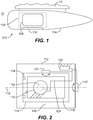
Fig. 1 is side elevation view of an exemplary embodiment of a sensor system constructed in accordance with the present disclosure, showing a gimbal arrangement of the sensor system; -
Fig. 2 is a side elevation view of the sensor system ofFig. 1 with the faring removed, schematically showing the gimbal arrangement and a magnetic soft stop; -
Fig. 3 is a axial end view of the sensor system ofFig. 1 with the faring removed, schematically showing first and second sensors carried by a roll gimbal with the magnetic soft stop arranged to limit rotation of the roll gimbal about a roll axis; -
Figs. 4 and 5 are axial end view of the sensor system ofFig. 1 with the faring removed, showing the gimbal in first and second positions; -
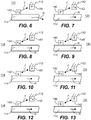
Figs. 6-13 are sectional views of the gimbal arrangement ofFig. 1 , schematically showing the magnetic soft stop implemented with permanent magnets and electromagnets; -
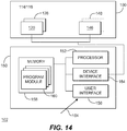
Fig. 14 is a schematic view of the sensor system ofFig. 2 , schematically showing a controller operatively connected to an electromagnet; and -
Fig. 15 is a block diagram of an imaging method, showing operations of the imaging method. - Reference will now be made to the drawings wherein like reference numerals identify similar structural features or aspects of the subject disclosure. For purposes of explanation and illustration, and not limitation, a sensor system with a gimbal arrangement having a magnetic soft stop is shown in
Fig. 1 and is generally indicated byreference character 100. Other embodiments of gimbal arrangements, sensor systems, and imaging methods are shown inFigs. 2-15 , as will be described. The systems and methods described herein can be used in intelligence surveillance and reconnaissance (ISR) sensor systems, such as in sensor systems having two or more sensors, though the present disclosure is not limited to ISR systems or to sensor systems having two or more sensors. - Referring to
Fig. 1 ,sensor system 102 is shown.Sensor system 102 includesgimbal arrangement 100 and is enveloped within the interior of a faring 104. Faring 104 includes awindow 106 which provides a viewing area for data collection from ascene 10 located outside of faring 104. In the illustratedexemplary embodiment window 106 is a first window and faring 104 includes at least one second window, e.g., a second window 108(shown inFig. 3 ) and athird window 110. It is contemplated thatsensor system 102 be arranged as an ISR sensor system, such as an ISR system carried by anaircraft 12. Examples of suitable ISR sensor systems include dual-band ISR sensor systems, such as DB-110 sensor systems, available United Technologies Aerospace Systems of Charlotte, North Carolina. - With reference to
Fig. 2 ,gimbal arrangement 100 is shown.Gimbal arrangement 100 includes astatic structure 112, aroll gimbal 114, andpitch gimbal 116. Faring 104 (shown inFig. 1 ) is fixed relative tostatic structure 112 and is supported thereby. Rollgimbal 114 is connected tostatic structure 112 and is supported thereby for rotation about aroll axis 118. Rotation ofroll gimbal 114 aboutroll axis 118 is effected by a roll resolver/drive arrangement 120, which is operably connected to rollgimbal 114 forrotating roll gimbal 114 aboutroll axis 118. As shown inFig. 2 acontroller 122 is disposed in communication with roll resolver/drive arrangement 120 throughcabling 124, through whichcontroller 122 controls rotation ofroll gimbal 114 aboutroll axis 118. -
Pitch gimbal 116 is connected to rollgimbal 114 and is supported thereby for rotation about apitch axis 126. Rotation ofpitch gimbal 116 aboutpitch axis 126 is effected by a pitch resolver/drive arrangement 128, which is operably connected to pitchgimbal 116 for rotatingpitch gimbal 116 aboutpitch axis 126 and which is itself carried byroll gimbal 114. As also shown inFig. 2 controller 122 is disposed in communication with pitch resolver/drive arrangement 128 throughcabling 124, through whichcontroller 122 also controls rotation ofpitch gimbal 116 aboutpitch axis 126. -
Pitch gimbal 116, andtherethrough roll gimbal 114, carry afirst sensor 130 and asecond sensor 132.Second sensor 132 is arranged on a side ofroll axis 118 oppositefirst sensor 130, either (or both)first sensor 130 andsecond sensor 132 being disposed in communication withcontroller 122 for receiving data from either (or both)first sensor 130 andsecond sensor 132. Data fromfirst sensor 130 andsecond sensor 132 is provided throughcabling 124, which provides connectivity for digital data communication between the sensors andcontroller 122. In certain embodiments cabling 124 is roll-flex type cabling. -
Controller 122 is fixed relative tostatic structure 112. Since cabling 124 runs between movable structures, e.g., pitch resolver/drive arrangement 128,first sensor 130, andsecond sensor 132, it is necessary to limit the movement of one or more of the movable structures relative tostatic structure 112. This prevents damage on cabling 124 that could otherwise occur from rotation ofroll gimbal 114. Limitation of movement ofroll gimbal 114 is effected by a magneticsoft stop 134. As will be appreciated by those of skill in the art in view of the present disclosure, the disadvantages otherwise associated with having to manage cabling 124 can be offset by the advantages provided by the quality of the data communication connection provided by cabling 124, which allowsfirst sensor 130 andsecond sensor 132 to communicate image data with the data loss that could otherwise accompany the use of a slip ring or other type of data communication interface. Although a particular magnetic soft stop arrangement is shown, e.g., magnetic soft stops connected to static structure and a fixed stop member connected to a gimbal, it is to be understood and appreciated that other arrangements are possible within the scope of the present disclosure. For example, magnetic soft stops can be carried by the gimbal. Further, pitch gimbal 14 can alternatively/additionally stopped using one or more magnetic soft stops, as suitable for an intended application. - With reference to
Fig. 3 ,sensor system 102 is shown in an axial end view. As shown inFig. 3 roll gimbal 114 extends aboutroll axis 118 and carriesfirst sensor 130 andsecond sensor 132.Static structure 112 extends aboutroll gimbal 114 and is located radially outward ofroll gimbal 114. Magneticsoft stop 134 is fixed relative tostatic structure 112.Second sensor 132 is arranged on a side ofroll axis 118 oppositefirst sensor 130 and has a second sensor field of 172. Second sensor field ofview 172 is smaller than a field ofview 162 offirst sensor 130. In certain embodimentsfirst sensor 130 can be a wide field of view sensor, such as optical waveband sensor. Examples of optical waveband sensors include cameras and telescopes. In accordance with certain embodimentssecond sensor 132 can be a narrow field of view sensor, such as an infrared waveband sensor. Examples of infrared sensors include infrared sub-waveband imaging arrays. - Referring to
Figs. 4 and 5 ,sensor system 102 andgimbal arrangement 100 are shown. Rollgimbal 114 has a plurality of rotational positions, e.g., a first position 136 (shown inFig. 4 ) and a second position 138 (shown inFig. 5 ) offset aboutroll axis 118 by 180 degrees. Roll resolver/drive arrangement 120 is operably connected to rollgimbal 114 and is configured and adapted to moveroll gimbal 114 betweenfirst position 136 andsecond position 138. Infirst position 136roll gimbal 114 has a rotary orientation aboutroll axis 118 such thatfirst sensor 130 is positioned proximate towindow 106 for viewing scene 10 (shown inFig. 1 ) throughwindow 106. Insecond position 138roll gimbal 114 is rotated 180 degrees relative tofirst position 136 such thatsecond sensor 132 is positioned proximate towindow 106 forimaging scene 10. - As will be appreciated by those of skill in the art, mechanical hard stops can be used to limit the rotation of gimbals. Mechanical hard stops have the advantage that the they can prevent movement of the gimbal from outside of the intended movement range of gimbal, e.g., outside of predetermined movement range, such as due acceleration and/or shocks that can be experienced by an aircraft carrying a sensor system carrying the sensor system. For example, the hard stop can physically interfere with the rotation of a gimbal beyond a certain amount of angular rotation about the rotation axis about which the gimbal is supported, potentially preventing damage to the sensor system and/or gimbal.
- While generally satisfactory for their intended purpose mechanical hard stops can potentially impose a shock on the sensor itself, such as when the gimbal strikes the hard stop. Mechanical hard stops also typically prevent use of the full range of rotation of the gimbal about the rotation about the rotation axis. This can potentially limit the sensing capability of the sensor system, such as when a sensor with a relatively wide field of view carried by the gimbal is replaced with a sensor having a relatively narrow field of view, the sensor with the narrow field of view having a smaller field of regard than the sensor with the wide field of regard for a given mechanical hard stop position. To limit end of travel shock and/or allow for adjustability of end
travel gimbal arrangement 100 includes magneticsoft stop 134. - Magnetic
soft stop 134 includes a firstmagnetic body 140 and a secondmagnetic body 142. Firstmagnetic body 140 is fixed relative to rollaxis 118 and can include, for example a permanent magnet 140 (P), a ferromagnetic body 142 (Fe), or an electromagnet, e.g.,electromagnet 146. Secondmagnetic body 142 is similar to firstmagnetic body 140 with the difference that secondmagnetic body 142 is movable relative to rollaxis 118, e.g., is carried byroll gimbal 114. It is contemplated that magnetic force F between firstmagnetic body 140 and secondmagnetic body 142 limit movement ofroll gimbal 114 to prevent rotary movement ofroll gimbal 114 beyond a predetermined movement range, illustrated in an exemplary way inFigs. 4 and 5 as about 180 degrees. As will be appreciated by those of skill in the art in view of the present disclosure, this can eliminate the need for a mechanical hard stop to limit rotary movement ofroll gimbal 114. In certain embodiments magneticsoft stop 134 can conform in fit and form to a hard stop for a DB-110 sensor system, which simplifies integration of magneticsoft stop 134 in such sensor systems. - Referring now to
Figs. 6 and 7 , magneticsoft stop 134 is shown. As shown inFig. 6 magneticsoft stop 134 can include apermanent magnet 140 fixed relative tostatic structure 112 and aferromagnetic member 142 fixed relative to rollgimbal 114. Use offerromagnetic member 142 andpermanent magnet 140 allowspermanent magnet 140 to cooperate to drawroll gimbal 114 into first position 136 (shown inFig. 4 ) and/or second position 138 (shown inFig. 5 ) using an attractive force F betweenferromagnetic member 142 andpermanent magnet 140. - As shown in
Fig. 8 ,permanent magnet 140 can be a first permanent magnet and magneticsoft stop 134 can include a secondpermanent magnet 144. Secondpermanent magnet 144 can be fixed relative to rollgimbal 114 such that, asroll gimbal 114 rotates secondpermanent magnet 144 into proximity of firstpermanent magnet 140 magnetic force F opposes rotation ofroll gimbal 114. Because the magnitude of magnetic force F corresponds to separation between firstpermanent magnet 140 and secondpermanent magnet 144, this has the effect a decelerating rotational speed ofroll gimbal 114 as secondpermanent magnet 144 approaches first permanent magnet 140- limiting the shock exerted onroll gimbal 114 as it reaches first position 136 (shown inFig. 4 ) or second position 138 (shown inFig. 5 ). - Referring to
Figs. 9-13 , it is contemplated that magneticsoft stop 134 include anelectromagnet 146. As shown inFig. 9 ,electromagnet 146 can be fixed relative tostatic structure 112 and can cooperate withpermanent magnet 140 to selectively generate magnetic force F. Alternatively, as shown inFig. 10 ,electromagnet 146 can be carried byroll gimbal 114 andpermanent magnet 140 can be fixed relative tostatic structure 112. Further,electromagnet 146 can cooperate withferromagnetic member 142 with one fixed relative tostatic structure 112 and the other fixed relative to rollgimbal 114, as shown inFigs. 11 and 12 . It is also contemplated thatelectromagnet 146 can be afirst electromagnet 146 and that magneticsoft stop 134 include a second magneticsoft stop 148, one offirst electromagnet 146 andsecond electromagnet 148 being fixed tostatic structure 112 and the other offirst electromagnet 146 andsecond electromagnet 148 being fixed to rollgimbal 114. As will be appreciated by those of skill in the art in view of the present disclosure, use ofelectromagnet 146 allows for selective engagement of magneticsoft stop 134 application of a control current to first electromagnetic 146 and/orsecond electromagnet 148. - Referring now to
Fig. 14 ,sensor system 102 is shown according to anembodiment having electromagnet 146 and acontroller 150.Controller 150 includes aprocessor 152, adevice interface 154, auser interface 156, and amemory 158.Memory 158 includes a non-transitory machine readable medium having instructions recorded in a plurality ofprogram modules 160 that, when read byprocessor 152,cause controller 150 to execute certain operations, e.g., operations of an imaging method 200 (shown inFig. 15 ), as will be described. In this respect, responsive to asensor selection input 164 received atuser interface 156,controller 150 causes roll resolver/drive arrangement 120 to rotateroll gimbal 114 aboutroll axis 118 and within a predetermined movement range bounded by magneticsoft stop 134, thereby presenting one of first sensor 130 (shown inFig. 2 ) and second sensor 132 (shown inFig. 2 ) to a window, e.g., first window 106 (shown inFig. 1 ), for imaging a scene. - It is contemplated that
rotating roll gimbal 114 aboutroll axis 118 can include energizing and/or de-energizingelectromagnet 146 and/orsecond electromagnet 148 to selectively cause magneticsoft stop 134 to bound the movement range ofroll gimbal 114. For example, whenfirst electromagnet 146 and/orsecond electromagnet 148 is energized,roll gimbal 114 can have a smaller movement range than whenfirst electromagnet 146 and/orsecond electromagnet 148 is not energized.Controller 150 can be implemented with software, circuitry, or a combination of both software circuitry. - Referring to
Fig. 15 , an imaging method 200 is shown. Imaging method 200 includes receiving, at a sensor system, e.g., sensor system 102 (shown inFig. 1 ), a sensor selection, as shown withbox 210. Based on the sensor selection the sensor system can rotation a gimbal, e.g., roll gimbal 114 (shown inFig. 2 ) of gimbal arrangement 100 (shown inFig. 1 ), between a first position a second position, e.g., first position 136 (shown inFig. 4 ) and second position 138 (shown inFig. 5 ), as shown withbox 220. In certain embodiments moving the gimbal between the first position and the second position can include energizing an electromagnet, e.g., first electromagnet 146 (shown inFig. 9 ) and/or second electromagnet 148 (shown inFig. 13 ). - Using the attractive and/or the repulsive force of the magnetic elements of the magnetic soft stop the magnetic soft stop slows rotation of the gimbal as the gimbal approaches the extreme of the movement range of the gimbal, as shown with
box 240. The attractive and/or repulsive force associated with the magnetic soft stop can be exerted on a ferromagnetic member, e.g., ferromagnetic member 142 (shown inFig. 6 ), as shown withbox 242. The attractive and/or repulsive force associated with the magnetic soft stop can be generated using a permanent magnet, e.g., permanent magnet 140 (shown inFig. 6 ), as shown withbox 244. The attractive and/or repulsive force associated with the magnetic soft stop can be generated using a first electromagnet, e.g., first electromagnet 146 (shown inFig. 9 ) and/or second electromagnet 148 (shown inFig. 13 ), as shown withbox 246. - Once the gimbal is in the first position or the second position a scene can be imaged using the imaging sensor, as shown with
box 250. It is contemplated that moving the gimbal between the first position and the second position can include rotating the gimbal beyond the magnetic soft stop location, such as more than 360 degrees, as shown withbox 260. - The methods and systems of the present disclosure, as described above and shown in the drawings, provide for sensor systems with superior properties including relatively low shock loadings in gimbal arrangements when the gimbal reaches the extreme of the gimbal movement range and/or the ability to rotate the gimbal move than 360 degrees without extension and/or damage sensor cabling connected to the gimbal. While the apparatus and methods of the subject disclosure have been shown and described with reference to preferred embodiments, those skilled in the art will readily appreciate that changes and/or modifications may be made thereto without departing from the scope of the subject disclosure.
Claims (15)
- A gimbal arrangement (100), comprising:a static structure (112);a gimbal (114) supported for rotation relative to the static structure (112);an actuator operably connected to the gimbal and configured to rotate the gimbal relative to the static structure; anda magnetic soft stop (134) connected between the static structure (112) and the gimbal (114) to limit rotation of the gimbal (114) relative to the static structure (112) to within a predetermined range.
- The gimbal arrangement as recited in claim 1, wherein the magnetic soft stop (134) includes an electromagnet.
- The gimbal arrangement as recited in claim 2, wherein the electromagnet is fixed relative to the static structure (112), or wherein the electromagnet is fixed relative to the gimbal.
- The gimbal arrangement as recited in any preceding claim, wherein the magnetic soft stop (134) includes a permanent magnet.
- The gimbal arrangement as recited in claim 5, wherein the permanent magnet is fixed relative to the static structure (112), or wherein the permanent magnet is fixed relative to the gimbal (114).
- The gimbal arrangement as recited in any preceding claim, wherein the magnetic soft stop (134) includes a ferromagnetic body.
- The gimbal arrangement as recited in claim 6, wherein the ferromagnetic body is fixed relative to the static structure (112), or wherein the ferromagnetic body is fixed relative to the gimbal (114).
- The gimbal arrangement as recited in any preceding claim, wherein there is no mechanical hard stop arranged between the gimbal (114) and the static structure (112).
- The gimbal arrangement as recited in any preceding claim, wherein the magnetic soft stop (134) conforms in fit and form of a mechanical hard stop for a DB-110 sensor system.
- The gimbal arrangement as recited in any preceding claim, further comprising a controller operably connected to the magnetic soft stop (134), wherein the controller is disposed in communication with a memory having instructions recorded on the memory to:activate the magnetic hard stop; andlimit rotation of the gimbal (114) relative to the static structure (112) to a predetermined range.
- The gimbal arrangement as recited in any preceding claim, further comprising a sensor fixed relative to the gimbal (114).
- The gimbal arrangement as recited in any preceding claim, wherein the gimbal (114) is arranged about a roll axis relative to the static structure, or wherein the gimbal (114) is arranged about a pitch axis relative to the static structure (112).
- The gimbal arrangement as recited in any preceding claim, wherein the gimbal is a first gimbal and further comprising a second gimbal (116), wherein the magnet is a first magnet, and further comprising:a second gimbal (116) supported for rotation relative to the first gimbal (114); anda second magnet arranged between the first gimbal (114) and the second gimbal (116), wherein the second magnetic soft stop is connected between the second gimbal and the first gimbal to limit rotation of the second gimbal relative to the first gimbal.
- A sensor system (102), comprising:a gimbal arrangement (100) as recited in any preceding claim;a sensor (130) fixed relative to the gimbal (114); anda controller operably connected to the magnetic soft stop (134), wherein the controller is disposed in communication with a memory having instructions recorded on the memory to:activate the magnetic hard stop; andlimit rotation of the gimbal relative to the static structure to a predetermined range, and optionally wherein magnetic soft stop (134) comprises:an electromagnet fixed relative to one of the static structure (112) and the gimbal (114); anda permanent magnet fixed relative to the other of the static structure (112) and the gimbal (114), wherein there is no mechanical hard stop arranged between the gimbal (114) and the static structure (112).
- An imaging method, comprising:at a gimbal arrangement comprising a static structure (112), a gimbal (114) supported for rotation relative to the static structure (112), an actuator operably connected to the gimbal (114) and configured to rotate the gimbal (114) relative to the static structure (112), and a magnetic soft stop connected between the static structure and the gimbal (114) to limit rotation of the gimbal relative to the static structure to within a predetermined range,limiting rotation of the gimbal (114) relative to the static structure to a predetermined range by communicating a magnetic force between the gimbal (114) and the static structure (114).
Applications Claiming Priority (1)
| Application Number | Priority Date | Filing Date | Title |
|---|---|---|---|
| US201862737057P | 2018-09-26 | 2018-09-26 |
Publications (1)
| Publication Number | Publication Date |
|---|---|
| EP3628909A1 true EP3628909A1 (en) | 2020-04-01 |
Family
ID=68069671
Family Applications (1)
| Application Number | Title | Priority Date | Filing Date |
|---|---|---|---|
| EP19199795.6A Pending EP3628909A1 (en) | 2018-09-26 | 2019-09-26 | Magnetic soft stops for gimbals |
Country Status (2)
| Country | Link |
|---|---|
| US (2) | US20200096153A1 (en) |
| EP (1) | EP3628909A1 (en) |
Families Citing this family (2)
| Publication number | Priority date | Publication date | Assignee | Title |
|---|---|---|---|---|
| EP3628910B1 (en) * | 2018-09-26 | 2022-01-12 | Goodrich Corporation | Mechanical hard stops with movable stop members |
| CN212588391U (en) * | 2020-07-06 | 2021-02-23 | 瑞声科技(南京)有限公司 | Camera module and electronic equipment |
Citations (3)
| Publication number | Priority date | Publication date | Assignee | Title |
|---|---|---|---|---|
| US5598207A (en) * | 1994-04-12 | 1997-01-28 | Hughes Electronics | Camera pointing mechanism using proximate magnetic sensing |
| US7602134B1 (en) * | 2006-07-20 | 2009-10-13 | L-3 Communications Sonoma Eo, Inc. | Twist capsule for rotatable payload |
| US20180113462A1 (en) * | 2016-10-22 | 2018-04-26 | Gopro, Inc. | Position-based soft stop for a 3-axis gimbal |
Family Cites Families (7)
| Publication number | Priority date | Publication date | Assignee | Title |
|---|---|---|---|---|
| JPS53108403A (en) | 1977-03-04 | 1978-09-21 | Sony Corp | Mirror supporting device for video disc |
| GB2439346B (en) * | 2006-06-19 | 2008-12-03 | Carel Van Der Walt | Improved gimbal |
| EP2151014B1 (en) * | 2007-05-10 | 2015-07-29 | ViaSat, Inc. | Spherical motor positioning |
| US10203717B2 (en) * | 2010-10-12 | 2019-02-12 | SeeScan, Inc. | Magnetic thumbstick user interface devices |
| US9182580B1 (en) | 2013-08-30 | 2015-11-10 | Checkpoint Technologies, Llc | Optical probe system having accurate positional and orientational adjustments for multiple optical objectives |
| DE102016004674B4 (en) | 2016-04-18 | 2024-07-18 | Kastriot Merlaku | Drive system for a camera |
| US10536630B2 (en) | 2018-01-05 | 2020-01-14 | Gopro, Inc. | Method and system for user feedback in a motion constrained image stabilization system |
-
2019
- 2019-09-26 EP EP19199795.6A patent/EP3628909A1/en active Pending
- 2019-09-26 US US16/584,379 patent/US20200096153A1/en not_active Abandoned
-
2022
- 2022-07-15 US US17/812,943 patent/US12516768B2/en active Active
Patent Citations (3)
| Publication number | Priority date | Publication date | Assignee | Title |
|---|---|---|---|---|
| US5598207A (en) * | 1994-04-12 | 1997-01-28 | Hughes Electronics | Camera pointing mechanism using proximate magnetic sensing |
| US7602134B1 (en) * | 2006-07-20 | 2009-10-13 | L-3 Communications Sonoma Eo, Inc. | Twist capsule for rotatable payload |
| US20180113462A1 (en) * | 2016-10-22 | 2018-04-26 | Gopro, Inc. | Position-based soft stop for a 3-axis gimbal |
Also Published As
| Publication number | Publication date |
|---|---|
| US20200096153A1 (en) | 2020-03-26 |
| US20230003337A1 (en) | 2023-01-05 |
| US12516768B2 (en) | 2026-01-06 |
Similar Documents
| Publication | Publication Date | Title |
|---|---|---|
| US11106118B2 (en) | Motor, gimbal having the motor, and image capturing device having the gimbal | |
| US12516768B2 (en) | Magnetic soft stops for gimbals | |
| US11181809B2 (en) | Focusing method, imaging device, and unmanned aerial vehicle | |
| US20240402704A1 (en) | Systems and methods for providing flight control for an unmanned aerial vehicle based on opposing fields of view with overlap | |
| US20180093768A1 (en) | Uav battery form factor and insertion/ejection methodologies | |
| US20200137312A1 (en) | Photographing device, photographing system, mobile body, control method and program | |
| CN111356954B (en) | Control device, moving body, control method, and program | |
| US9630714B1 (en) | Systems and methods for providing flight control for an unmanned aerial vehicle based on tilted optical elements | |
| DE202018105070U1 (en) | Bearing design for an electric motor | |
| US20180113462A1 (en) | Position-based soft stop for a 3-axis gimbal | |
| US10053230B2 (en) | Magnetic levitation obstacle avoidance device and magnetic levitation holder | |
| JP6957304B2 (en) | Overhead line photography system and overhead line photography method | |
| US20170254473A1 (en) | Gimbals | |
| CN106494635A (en) | The floating obstacle avoidance apparatus of magnetic and magnetic floating clouds platform | |
| US10331120B2 (en) | Remote control device, control system and method of controlling | |
| CN107005102A (en) | System and method for being supported to compact servo system | |
| KR101569713B1 (en) | Picture image processing system with real time updating of picture image | |
| WO2020062089A1 (en) | Magnetic sensor calibration method and movable platform | |
| US20220082199A1 (en) | Mechanical hard stops with moveable stop members | |
| KR20190109100A (en) | Plural Drone Configuration and Method Thereof | |
| CN110383228B (en) | Generation device, generation system, imaging system, mobile object, and generation method | |
| CN206407153U (en) | Magnetic floats obstacle avoidance apparatus and magnetic floating clouds platform | |
| AU2016344526B2 (en) | An air vehicle and imaging apparatus therefor | |
| US20210231908A1 (en) | Control device, camera device, control method, and program | |
| KR102502090B1 (en) | Unmanned aerial vehicle equipped with camera |
Legal Events
| Date | Code | Title | Description |
|---|---|---|---|
| PUAI | Public reference made under article 153(3) epc to a published international application that has entered the european phase |
Free format text: ORIGINAL CODE: 0009012 |
|
| STAA | Information on the status of an ep patent application or granted ep patent |
Free format text: STATUS: THE APPLICATION HAS BEEN PUBLISHED |
|
| AK | Designated contracting states |
Kind code of ref document: A1 Designated state(s): AL AT BE BG CH CY CZ DE DK EE ES FI FR GB GR HR HU IE IS IT LI LT LU LV MC MK MT NL NO PL PT RO RS SE SI SK SM TR |
|
| AX | Request for extension of the european patent |
Extension state: BA ME |
|
| STAA | Information on the status of an ep patent application or granted ep patent |
Free format text: STATUS: REQUEST FOR EXAMINATION WAS MADE |
|
| 17P | Request for examination filed |
Effective date: 20200930 |
|
| RBV | Designated contracting states (corrected) |
Designated state(s): AL AT BE BG CH CY CZ DE DK EE ES FI FR GB GR HR HU IE IS IT LI LT LU LV MC MK MT NL NO PL PT RO RS SE SI SK SM TR |
|
| STAA | Information on the status of an ep patent application or granted ep patent |
Free format text: STATUS: EXAMINATION IS IN PROGRESS |
|
| 17Q | First examination report despatched |
Effective date: 20210903 |
|
| P01 | Opt-out of the competence of the unified patent court (upc) registered |
Effective date: 20230922 |
|
| RIN1 | Information on inventor provided before grant (corrected) |
Inventor name: LANGE, DAVIS Inventor name: ASSELIN, LUKE N. Inventor name: HELMKE, CHRISTOPHER WILLIAM |
|
| GRAP | Despatch of communication of intention to grant a patent |
Free format text: ORIGINAL CODE: EPIDOSNIGR1 |
|
| STAA | Information on the status of an ep patent application or granted ep patent |
Free format text: STATUS: GRANT OF PATENT IS INTENDED |
|
| INTG | Intention to grant announced |
Effective date: 20260212 |