EP3628893B1 - Drive-force transmitting apparatus for vehicle - Google Patents
Drive-force transmitting apparatus for vehicle Download PDFInfo
- Publication number
- EP3628893B1 EP3628893B1 EP19184629.4A EP19184629A EP3628893B1 EP 3628893 B1 EP3628893 B1 EP 3628893B1 EP 19184629 A EP19184629 A EP 19184629A EP 3628893 B1 EP3628893 B1 EP 3628893B1
- Authority
- EP
- European Patent Office
- Prior art keywords
- pump
- drive
- rotor
- force transmitting
- pump body
- Prior art date
- Legal status (The legal status is an assumption and is not a legal conclusion. Google has not performed a legal analysis and makes no representation as to the accuracy of the status listed.)
- Active
Links
Images


Classifications
-
- F—MECHANICAL ENGINEERING; LIGHTING; HEATING; WEAPONS; BLASTING
- F16—ENGINEERING ELEMENTS AND UNITS; GENERAL MEASURES FOR PRODUCING AND MAINTAINING EFFECTIVE FUNCTIONING OF MACHINES OR INSTALLATIONS; THERMAL INSULATION IN GENERAL
- F16H—GEARING
- F16H57/00—General details of gearing
- F16H57/04—Features relating to lubrication or cooling or heating
- F16H57/0434—Features relating to lubrication or cooling or heating relating to lubrication supply, e.g. pumps; Pressure control
- F16H57/0436—Pumps
-
- B—PERFORMING OPERATIONS; TRANSPORTING
- B60—VEHICLES IN GENERAL
- B60W—CONJOINT CONTROL OF VEHICLE SUB-UNITS OF DIFFERENT TYPE OR DIFFERENT FUNCTION; CONTROL SYSTEMS SPECIALLY ADAPTED FOR HYBRID VEHICLES; ROAD VEHICLE DRIVE CONTROL SYSTEMS FOR PURPOSES NOT RELATED TO THE CONTROL OF A PARTICULAR SUB-UNIT
- B60W10/00—Conjoint control of vehicle sub-units of different type or different function
- B60W10/04—Conjoint control of vehicle sub-units of different type or different function including control of propulsion units
-
- F—MECHANICAL ENGINEERING; LIGHTING; HEATING; WEAPONS; BLASTING
- F04—POSITIVE - DISPLACEMENT MACHINES FOR LIQUIDS; PUMPS FOR LIQUIDS OR ELASTIC FLUIDS
- F04C—ROTARY-PISTON, OR OSCILLATING-PISTON, POSITIVE-DISPLACEMENT MACHINES FOR LIQUIDS; ROTARY-PISTON, OR OSCILLATING-PISTON, POSITIVE-DISPLACEMENT PUMPS
- F04C2/00—Rotary-piston machines or pumps
- F04C2/08—Rotary-piston machines or pumps of intermeshing-engagement type, i.e. with engagement of co-operating members similar to that of toothed gearing
- F04C2/10—Rotary-piston machines or pumps of intermeshing-engagement type, i.e. with engagement of co-operating members similar to that of toothed gearing of internal-axis type with the outer member having more teeth or tooth-equivalents, e.g. rollers, than the inner member
- F04C2/102—Rotary-piston machines or pumps of intermeshing-engagement type, i.e. with engagement of co-operating members similar to that of toothed gearing of internal-axis type with the outer member having more teeth or tooth-equivalents, e.g. rollers, than the inner member the two members rotating simultaneously around their respective axes
-
- B—PERFORMING OPERATIONS; TRANSPORTING
- B60—VEHICLES IN GENERAL
- B60K—ARRANGEMENT OR MOUNTING OF PROPULSION UNITS OR OF TRANSMISSIONS IN VEHICLES; ARRANGEMENT OR MOUNTING OF PLURAL DIVERSE PRIME-MOVERS IN VEHICLES; AUXILIARY DRIVES FOR VEHICLES; INSTRUMENTATION OR DASHBOARDS FOR VEHICLES; ARRANGEMENTS IN CONNECTION WITH COOLING, AIR INTAKE, GAS EXHAUST OR FUEL SUPPLY OF PROPULSION UNITS IN VEHICLES
- B60K6/00—Arrangement or mounting of plural diverse prime-movers for mutual or common propulsion, e.g. hybrid propulsion systems comprising electric motors and internal combustion engines
- B60K6/20—Arrangement or mounting of plural diverse prime-movers for mutual or common propulsion, e.g. hybrid propulsion systems comprising electric motors and internal combustion engines the prime-movers consisting of electric motors and internal combustion engines, e.g. HEVs
- B60K6/22—Arrangement or mounting of plural diverse prime-movers for mutual or common propulsion, e.g. hybrid propulsion systems comprising electric motors and internal combustion engines the prime-movers consisting of electric motors and internal combustion engines, e.g. HEVs characterised by apparatus, components or means specially adapted for HEVs
- B60K6/36—Arrangement or mounting of plural diverse prime-movers for mutual or common propulsion, e.g. hybrid propulsion systems comprising electric motors and internal combustion engines the prime-movers consisting of electric motors and internal combustion engines, e.g. HEVs characterised by apparatus, components or means specially adapted for HEVs characterised by the transmission gearings
-
- B—PERFORMING OPERATIONS; TRANSPORTING
- B60—VEHICLES IN GENERAL
- B60K—ARRANGEMENT OR MOUNTING OF PROPULSION UNITS OR OF TRANSMISSIONS IN VEHICLES; ARRANGEMENT OR MOUNTING OF PLURAL DIVERSE PRIME-MOVERS IN VEHICLES; AUXILIARY DRIVES FOR VEHICLES; INSTRUMENTATION OR DASHBOARDS FOR VEHICLES; ARRANGEMENTS IN CONNECTION WITH COOLING, AIR INTAKE, GAS EXHAUST OR FUEL SUPPLY OF PROPULSION UNITS IN VEHICLES
- B60K6/00—Arrangement or mounting of plural diverse prime-movers for mutual or common propulsion, e.g. hybrid propulsion systems comprising electric motors and internal combustion engines
- B60K6/20—Arrangement or mounting of plural diverse prime-movers for mutual or common propulsion, e.g. hybrid propulsion systems comprising electric motors and internal combustion engines the prime-movers consisting of electric motors and internal combustion engines, e.g. HEVs
- B60K6/50—Architecture of the driveline characterised by arrangement or kind of transmission units
-
- F—MECHANICAL ENGINEERING; LIGHTING; HEATING; WEAPONS; BLASTING
- F04—POSITIVE - DISPLACEMENT MACHINES FOR LIQUIDS; PUMPS FOR LIQUIDS OR ELASTIC FLUIDS
- F04C—ROTARY-PISTON, OR OSCILLATING-PISTON, POSITIVE-DISPLACEMENT MACHINES FOR LIQUIDS; ROTARY-PISTON, OR OSCILLATING-PISTON, POSITIVE-DISPLACEMENT PUMPS
- F04C15/00—Component parts, details or accessories of machines, pumps or pumping installations, not provided for in groups F04C2/00 - F04C14/00
-
- F—MECHANICAL ENGINEERING; LIGHTING; HEATING; WEAPONS; BLASTING
- F04—POSITIVE - DISPLACEMENT MACHINES FOR LIQUIDS; PUMPS FOR LIQUIDS OR ELASTIC FLUIDS
- F04C—ROTARY-PISTON, OR OSCILLATING-PISTON, POSITIVE-DISPLACEMENT MACHINES FOR LIQUIDS; ROTARY-PISTON, OR OSCILLATING-PISTON, POSITIVE-DISPLACEMENT PUMPS
- F04C15/00—Component parts, details or accessories of machines, pumps or pumping installations, not provided for in groups F04C2/00 - F04C14/00
- F04C15/0057—Driving elements, brakes, couplings, transmission specially adapted for machines or pumps
- F04C15/0061—Means for transmitting movement from the prime mover to driven parts of the pump, e.g. clutches, couplings, transmissions
-
- F—MECHANICAL ENGINEERING; LIGHTING; HEATING; WEAPONS; BLASTING
- F16—ENGINEERING ELEMENTS AND UNITS; GENERAL MEASURES FOR PRODUCING AND MAINTAINING EFFECTIVE FUNCTIONING OF MACHINES OR INSTALLATIONS; THERMAL INSULATION IN GENERAL
- F16H—GEARING
- F16H57/00—General details of gearing
- F16H57/02—Gearboxes; Mounting gearing therein
- F16H57/028—Gearboxes; Mounting gearing therein characterised by means for reducing vibration or noise
-
- F—MECHANICAL ENGINEERING; LIGHTING; HEATING; WEAPONS; BLASTING
- F16—ENGINEERING ELEMENTS AND UNITS; GENERAL MEASURES FOR PRODUCING AND MAINTAINING EFFECTIVE FUNCTIONING OF MACHINES OR INSTALLATIONS; THERMAL INSULATION IN GENERAL
- F16H—GEARING
- F16H57/00—General details of gearing
- F16H57/04—Features relating to lubrication or cooling or heating
- F16H57/0434—Features relating to lubrication or cooling or heating relating to lubrication supply, e.g. pumps; Pressure control
- F16H57/0441—Arrangements of pumps
-
- F—MECHANICAL ENGINEERING; LIGHTING; HEATING; WEAPONS; BLASTING
- F16—ENGINEERING ELEMENTS AND UNITS; GENERAL MEASURES FOR PRODUCING AND MAINTAINING EFFECTIVE FUNCTIONING OF MACHINES OR INSTALLATIONS; THERMAL INSULATION IN GENERAL
- F16H—GEARING
- F16H61/00—Control functions within control units of change-speed- or reversing-gearings for conveying rotary motion ; Control of exclusively fluid gearing, friction gearing, gearings with endless flexible members or other particular types of gearing
- F16H61/0021—Generation or control of line pressure
- F16H61/0025—Supply of control fluid; Pumps therefor
-
- F—MECHANICAL ENGINEERING; LIGHTING; HEATING; WEAPONS; BLASTING
- F16—ENGINEERING ELEMENTS AND UNITS; GENERAL MEASURES FOR PRODUCING AND MAINTAINING EFFECTIVE FUNCTIONING OF MACHINES OR INSTALLATIONS; THERMAL INSULATION IN GENERAL
- F16N—LUBRICATING
- F16N13/00—Lubricating-pumps
- F16N13/20—Rotary pumps
-
- B—PERFORMING OPERATIONS; TRANSPORTING
- B60—VEHICLES IN GENERAL
- B60K—ARRANGEMENT OR MOUNTING OF PROPULSION UNITS OR OF TRANSMISSIONS IN VEHICLES; ARRANGEMENT OR MOUNTING OF PLURAL DIVERSE PRIME-MOVERS IN VEHICLES; AUXILIARY DRIVES FOR VEHICLES; INSTRUMENTATION OR DASHBOARDS FOR VEHICLES; ARRANGEMENTS IN CONNECTION WITH COOLING, AIR INTAKE, GAS EXHAUST OR FUEL SUPPLY OF PROPULSION UNITS IN VEHICLES
- B60K6/00—Arrangement or mounting of plural diverse prime-movers for mutual or common propulsion, e.g. hybrid propulsion systems comprising electric motors and internal combustion engines
- B60K6/20—Arrangement or mounting of plural diverse prime-movers for mutual or common propulsion, e.g. hybrid propulsion systems comprising electric motors and internal combustion engines the prime-movers consisting of electric motors and internal combustion engines, e.g. HEVs
- B60K6/42—Arrangement or mounting of plural diverse prime-movers for mutual or common propulsion, e.g. hybrid propulsion systems comprising electric motors and internal combustion engines the prime-movers consisting of electric motors and internal combustion engines, e.g. HEVs characterised by the architecture of the hybrid electric vehicle
- B60K6/44—Series-parallel type
- B60K6/445—Differential gearing distribution type
-
- F—MECHANICAL ENGINEERING; LIGHTING; HEATING; WEAPONS; BLASTING
- F04—POSITIVE - DISPLACEMENT MACHINES FOR LIQUIDS; PUMPS FOR LIQUIDS OR ELASTIC FLUIDS
- F04C—ROTARY-PISTON, OR OSCILLATING-PISTON, POSITIVE-DISPLACEMENT MACHINES FOR LIQUIDS; ROTARY-PISTON, OR OSCILLATING-PISTON, POSITIVE-DISPLACEMENT PUMPS
- F04C2240/00—Components
- F04C2240/10—Stators
-
- F—MECHANICAL ENGINEERING; LIGHTING; HEATING; WEAPONS; BLASTING
- F04—POSITIVE - DISPLACEMENT MACHINES FOR LIQUIDS; PUMPS FOR LIQUIDS OR ELASTIC FLUIDS
- F04C—ROTARY-PISTON, OR OSCILLATING-PISTON, POSITIVE-DISPLACEMENT MACHINES FOR LIQUIDS; ROTARY-PISTON, OR OSCILLATING-PISTON, POSITIVE-DISPLACEMENT PUMPS
- F04C2240/00—Components
- F04C2240/20—Rotors
-
- F—MECHANICAL ENGINEERING; LIGHTING; HEATING; WEAPONS; BLASTING
- F04—POSITIVE - DISPLACEMENT MACHINES FOR LIQUIDS; PUMPS FOR LIQUIDS OR ELASTIC FLUIDS
- F04C—ROTARY-PISTON, OR OSCILLATING-PISTON, POSITIVE-DISPLACEMENT MACHINES FOR LIQUIDS; ROTARY-PISTON, OR OSCILLATING-PISTON, POSITIVE-DISPLACEMENT PUMPS
- F04C2240/00—Components
- F04C2240/30—Casings or housings
-
- F—MECHANICAL ENGINEERING; LIGHTING; HEATING; WEAPONS; BLASTING
- F04—POSITIVE - DISPLACEMENT MACHINES FOR LIQUIDS; PUMPS FOR LIQUIDS OR ELASTIC FLUIDS
- F04C—ROTARY-PISTON, OR OSCILLATING-PISTON, POSITIVE-DISPLACEMENT MACHINES FOR LIQUIDS; ROTARY-PISTON, OR OSCILLATING-PISTON, POSITIVE-DISPLACEMENT PUMPS
- F04C2240/00—Components
- F04C2240/60—Shafts
-
- F—MECHANICAL ENGINEERING; LIGHTING; HEATING; WEAPONS; BLASTING
- F16—ENGINEERING ELEMENTS AND UNITS; GENERAL MEASURES FOR PRODUCING AND MAINTAINING EFFECTIVE FUNCTIONING OF MACHINES OR INSTALLATIONS; THERMAL INSULATION IN GENERAL
- F16H—GEARING
- F16H57/00—General details of gearing
- F16H57/02—Gearboxes; Mounting gearing therein
- F16H2057/02026—Connection of auxiliaries with a gear case; Mounting of auxiliaries on the gearbox
-
- Y—GENERAL TAGGING OF NEW TECHNOLOGICAL DEVELOPMENTS; GENERAL TAGGING OF CROSS-SECTIONAL TECHNOLOGIES SPANNING OVER SEVERAL SECTIONS OF THE IPC; TECHNICAL SUBJECTS COVERED BY FORMER USPC CROSS-REFERENCE ART COLLECTIONS [XRACs] AND DIGESTS
- Y02—TECHNOLOGIES OR APPLICATIONS FOR MITIGATION OR ADAPTATION AGAINST CLIMATE CHANGE
- Y02T—CLIMATE CHANGE MITIGATION TECHNOLOGIES RELATED TO TRANSPORTATION
- Y02T10/00—Road transport of goods or passengers
- Y02T10/60—Other road transportation technologies with climate change mitigation effect
- Y02T10/62—Hybrid vehicles
Definitions
- the present invention relates to a drive-force transmitting apparatus for a vehicle, and is more particularly concerned with a structure for disposing a fluid pump in the drive-force transmitting apparatus.
- a drive-force transmitting apparatus for a vehicle, wherein the transmitting apparatus includes: a drive gear that serves as a drive-force transmitting member configured to transmit a drive force from the drive force source to the drive wheels; a fluid pump that is to driven by rotation of the drive gear; and a casing that stores therein the drive gear and the fluid pump.
- JP-2011-174583A discloses such a drive-force transmitting apparatus for a vehicle.
- the fluid chamber includes: a pump body that defines therein a pump chamber; a pump cover that covers the pump chamber and is fixed to the pump body; a rotor that is disposed in the pump chamber; a driven gear that meshes with the drive gear; and a pump shaft on which the rotor and the driven gear are mounted.
- the fluid pump is in close contact with the casing so as to be attached to the casing, such that the pump cover is fitted in a recess provided in a wall surface of the casing. Owing to this arrangement, when the fluid pump is assembled into the casing, the rotor is prevented from being removed from the pump chamber whereby an assemblability of the fluid pump is improved.
- the present invention was made in view of the background art described above. It is therefore an object of the present invention to provide a drive-force transmitting apparatus for a vehicle, which is capable of damping vibration generated by drive of a fluid pump, so as to reduce noise that is emitted to outside the casing.
- a drive-force transmitting apparatus for a vehicle that includes a drive force source and drive wheels.
- the drive-force transmitting apparatus includes: a drive gear that serves as a drive-force transmitting member configured to transmit a drive force from the drive force source to the drive wheels; a fluid pump that is to driven by rotation of the drive gear; and a casing that stores therein the drive gear and the fluid pump.
- the fluid pump includes: a pump body that defines therein a pump chamber; a pump cover that covers the pump chamber and is fixed to the pump body; a rotor that is disposed in the pump chamber; a driven gear that meshes with the drive gear; and a pump shaft on which the rotor and the driven gear are mounted, wherein the pump shaft has a supported portion and a free end portion, such that the pump shaft is rotatably supported at the supported portion by at least one of the pump body and the pump cover, and such that the driven gear is mounted on the free end portion of the pump shaft, wherein the pump body has an outer peripheral portion that is located on an outer side of the pump body in a radial direction of the rotor, and the pump cover has an outer peripheral portion that is located on an outer side of the pump cover in the radial direction, and wherein one of the outer peripheral portion of the pump body and the outer peripheral portion of the pump cover is supported by the casing, and the rest of the pump body and the rest of the pump cover are spaced apart from the cas
- the pump shaft may be a cantilever shaft, and is may be rotatably supported by the pump body and the pump cover, such that the rotor is fitted on an end portion of the pump shaft while the driven gear is fitted on another end portion of the pump shaft.
- the one of the outer peripheral portion of the pump body and the outer peripheral portion of the pump cover may include a plurality of connected portions that are connected to a plurality of connected portions of an inside wall surface of the casing through respective protrusions that extend between the plurality of connected portions of the above-described one and the plurality of connected portions of the inside wall surface, such that the rest of the pump body and the rest of the pump cover are spaced from at least a portion of the inside wall surface of the casing which is located between the plurality of connected portions of the inside wall surface of the casing.
- the plurality of connected portions of the one of the outer peripheral portion of the pump body and the outer peripheral portion of the pump cover may consist of at least three connected portions
- the plurality of connected portions of the inside wall surface of the casing may consist of at least three connected portions, such that the portion of the inside wall surface of the casing, which is spaced apart from the rest of the pump body and the rest of the pump cover, is located between the at least three connected portions of the inside wall surface of the casing.
- the outer peripheral portion of the pump body and the outer peripheral portion of the pump cover are located on an outer side of an outer periphery of the rotor in the radial direction.
- the pump shaft is a stepped shaft having a step, wherein the rotor, which is mounted on the pump shaft, has axially opposite end surfaces that are opposite to each other in an axial direction of the pump shaft, such that one of the axially opposite end surfaces of the rotor, which is closer to the free end portion of the pump shaft than the other of the axially opposite end surfaces, is in contact with the step of the pump shaft.
- the rotor is limited, by the step of the pump shaft, from being displaced relative to the pump shaft in a first direction that is parallel to the axial direction, wherein the driven gear is a helical gear, and wherein, when the driven gear is driven by the drive gear during forward running of the vehicle, a thrust load is applied to the driven gear and acts in a second direction that is opposite to the first direction.
- the pump body has a sliding contact surface which is perpendicular to the axial direction and which is in sliding contact with the other of the axially opposite end surfaces of the rotor, wherein at least part of the thrust load is received by the sliding contact surface of the pump body.
- the pump body has a fluid inlet and a fluid discharge passage such that a fluid is introduced through the fluid inlet from outside the pump body and such that the fluid is discharged through the fluid discharge passage to outside the pump body, wherein the second direction is substantially the same as a discharge direction in which the fluid flows to be discharged through the fluid discharge passage.
- At least a part of the fluid discharge passage is located on an inner side of an outer periphery of the rotor in the radial direction.
- the pump shaft has the supported portion and the free end portion, such that the pump shaft is rotatably supported at the supported portion by at least one of the pump body and the pump cover, and such that the driven gear is mounted on the free end portion of the pump shaft, wherein the pump body has the outer peripheral portion that is located on the outer side of the other portion of the pump body in the radial direction of the rotor, and the pump cover has the outer peripheral portion that is located on the outer side of the other portion of the pump cover in the radial direction, and wherein one of the outer peripheral portion of the pump body and the outer peripheral portion of the pump cover is supported by the casing, and the rest of the pump body and the rest of the pump cover are spaced apart from the casing.
- the outer peripheral portion of the pump body and the outer peripheral portion of the pump cover are located on the outer side of the outer periphery of the rotor in the radial direction. Owing to this arrangement, in the drive-force transmitting apparatus, it is possible to further increase the vibration transmission path from the vibration generating source of the fluid pump to the casing. Thus, it is possible to further damp the vibration generated in the rotor or the meshing portions of the drive and drive gears, and accordingly to further reduce the noise that is emitted to outside the casing.
- the pump shaft is the stepped shaft having the step, wherein the rotor, which is mounted on the pump shaft, has the axially opposite end surfaces that are opposite to each other in the axial direction of the pump shaft, such that one of the axially opposite end surfaces of the rotor, which is closer to the free end portion of the pump shaft than the other of the axially opposite end surfaces, is in contact with the step of the pump shaft.
- movement of the rotor relative to the pump shaft in the axial direction is structurally limited, so that the rotor can be positioned in a desired position relative to the pump shaft in the axial direction, by a simple construction without an additional member such as a positioning member.
- the rotor is limited, by the step of the pump shaft, from being displaced relative to the pump shaft in the first direction that is parallel to the axial direction, wherein the driven gear is the helical gear, and wherein, when the driven gear is driven by the drive gear during forward running of the vehicle, the thrust load is applied to the driven gear and acts in the second direction that is opposite to the first direction.
- the thrust load is applied to the driven gear as the helical gear in a direction in which the pump shaft is introduced into the rotor, so that it is possible to reduce frequency of occurrence of a load forcing the pump shaft to be removed from the rotor.
- an additional element such as a ball bearing and a bushing and an additional support structure for the casing are not required, whereby the fitting of the rotor and the pump shaft can be made by a simple construction.
- the pump body has the sliding contact surface which is perpendicular to the axial direction and which is in sliding contact with the other of the axially opposite end surfaces of the rotor, wherein the thrust load or a part of the thrust load is received by the sliding contact surface of the pump body.
- the pump body has the fluid inlet and the fluid discharge passage such that the fluid is introduced through the fluid inlet from outside the pump body and such that the fluid is discharged through the fluid discharge passage to outside the pump body, wherein the second direction is substantially the same as the discharge direction in which the fluid flows to be discharged through the fluid discharge passage.
- the second direction i.e., the direction in which the thrust load is applied from the driven gear to the rotor, is opposite to a direction of a discharge reaction force of the fluid discharged through the fluid discharge passage, so that the thrust load applied from the driven gear to the rotor and the discharge reaction force applied from the fluid to the rotor can be offset by each other. Therefore, it is possible to reduce a surface pressure acting on the rotor thereby leading to an improvement of durability of the rotor.
- At least a part of the fluid discharge passage is located on an inner side of an outer periphery of the rotor in the radial direction.
- the present invention is applicable to a drive-force transmitting apparatus for any type of vehicle such as a vehicle which is to be driven by an internal combustion engine as a drive force source, a hybrid vehicle which has not only the engine but also an electric motor as another drive force source and which is to be driven by the engine and the electric motor, and an electric motor which has only an electric motor as a drive force source and which is to be driven by the electric motor.
- the drive-force transmitting apparatus may be a transaxle that is to be installed in a FR (front engine - rear drive) vehicle or a four-wheel drive vehicle, or may be a transaxle of lateral installation type that is to be installed in a FF (front engine - front drive) vehicle such that a plurality of axes are arranged in parallel to a lateral (transverse) direction of the vehicle.
- FR front engine - rear drive
- FF front engine - front drive
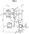
- FIG. 1 is a schematic view showing a transaxle, i.e., drive-force transmitting apparatus 12 for a vehicle 10, to which the present invention is applied.
- the view of FIG. 1 is a development view illustrating the drive-force transmitting apparatus 12 in a manner in which a plurality of axes of a drive-force transmitting mechanism 16 of the drive-force transmitting apparatus 12 are contained in a single plane.
- the drive-force transmitting apparatus 12 is configured to transmit an output of the engine 20 to right and left drive wheels 38.
- the drive-force transmitting apparatus 12 is of a lateral installation type that is to be installed in a FF vehicle, for example, and a plurality of axes of the drive-force transmitting mechanism 16, which is disposed in the casing 14, are arranged in parallel to a lateral direction of the vehicle 10.
- the engine 20 is an internal combustion engine such as a gasoline engine or a diesel engine, which is configured to generate a drive force by combustion of a fuel.
- the casing 14 may be constituted by a single member or a plurality of members that are fixed to each other.
- the drive-force transmitting mechanism 16 has first through fourth axes S1-S4 that substantially parallel to the lateral direction of the vehicle 10.
- An input shaft 22 is disposed on the first axis S1, and is connected to the engine 20 serving as a drive force source for driving the vehicle 10.
- a planetary gear device 24 of a single-pinion type and a first motor generator MG1 are disposed to be coaxial with the first axis S1.
- the planetary gear device 24 and the first motor generator MG1 cooperate with each other to constitute an electrically-controlled differential portion 26.
- the planetary gear device 24 which constitutes a differential mechanism, has a first rotary element in the form of a carrier 24c that is connected to the input shaft 22, a second rotary element in the form of a sun gear 24s connected to the first motor generator MG1 and a third rotary element in the form of a ring gear 24r provided integrally with an engine output gear Ge.
- the first motor generator MG1 which constitutes a differential-control rotating machine, is to be operated selectively as an electric motor and a generator.
- a rotational speed of the sun gear 24s is controlled in a continuously changing manner, whereby a rotational speed transmitted from the engine 20 is continuously changed and is outputted through the engine output gear Ge. Further, when a torque of the first motor generator MG1 is controlled to zero, the sun gear 24s is idled or freely rotated whereby transmission of the drive force between the engine 20 and the drive-force transmitting mechanism 16 is interrupted so that dragging of the engine 20 is prevented.
- the large reduction gear Gr1 meshes with the above-described engine output gear Ge, and also with a motor output gear Gm of a second motor generator MG2 which is disposed on the third axis S3.
- the second motor generator MG2, which constitutes a vehicle-driving rotating machine, is to be operated selectively as an electric motor and a generator. For example, in a power running control in which the second motor generator MG2 is operated as the electric motor, the second motor generator MG2 serves as another drive force source for driving the vehicle 10.
- the small reduction gear Gr2 meshes with a differential ring gear Gd of a differential device 32 that is disponed on the fourth axis S4, so that the drive force transmitted from the engine 20 and/or the second motor generator MG2 is distributed to right and left drive axles 36 through the differential device 32 and is then transmitted to the right and left drive wheels 38.
- the differential ring gear Gd corresponds to "drive gear” recited in the appended claims.
- the differential device 32 constitutes an output portion, and the differential ring gear Gd constitutes an input gear.
- the engine output gear Ge, large reduction gear Gr1, small reduction gear Gr2 and differential ring gear Gd cooperate with one another to constitute at least a part of a gear mechanism.
- first oil pump P1 and a second oil pump P2 as lubrication fluid sources of a lubricating device (not shown).
- the first and second oil pumps PI, P2 are connected to respective fluid supply passages that are independent from each other, so as to lubricate respective assigned parts of the drive-force transmitting mechanism 16.
- the first oil pump P1 is a mechanical pump that is to be mechanically driven through a driven gear Gp (described below) that meshes with a differential ring gear Gd (described below)
- the second oil pump P2 is a mechanical pump that is connected to the input shaft 22 so as to be mechanically driven through the engine 20.
- the first and second oil pumps PI, P2 are both disposed within the casing 14. It is noted that the first oil pump P1 may be modified such that the first oil pump P1 is to be driven by adapting the driven gear Gp to mesh with the large reduction gear Gr1 or small reduction gear Gr2 that are rotatable with the differential ring gear Gd.
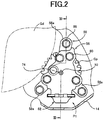
- FIG. 2 is view showing, in enlargement, a part of the drive-force transmitting apparatus 12 shown in FIG. 1 .
- FIG. 2 shows a construction of a main portion of the first oil pump P1 and a surrounding of the main portion, namely, a positional relationship between the differential ring gear Gd and the driven gear Gp that mesh with each other, wherein the differential ring gear Gd serves as a drive-force transmitting member of the drive-force transmitting mechanism 16 and also as a drive gear for driving the first oil pump PI, while the driven gear Gp is an element included in the first oil pump P1.
- FIG. 3 is a cross sectional view taken in line III-III indicated in FIG. 2 . An upward direction in FIG.
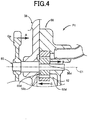
- FIGS. 4 and 5 are views showing, in enlargement, a part of the first oil pump P1 shown in FIG. 3 .
- the driven gear Gp of the first oil pump P1 meshes with the differential ring gear Gd provided in the drive-force transmitting mechanism 16, so that the first oil pump P1 is operated or driven with running of the vehicle 10.
- the first oil pump P1 includes, in addition to the driven gear Gp meshing with the differential ring gear Gd, a pump shaft 50 on which the driven gear Gp is mounted, a rotor 52 mounted on the pump shaft 50, a pump body 56 defining therein a pump chamber 54, and a pump cover 58 that is fixed to the pump body 56 so as to cover the pump chamber 54.
- the rotor 52 is disposed in the pump chamber 54.
- the pump shaft 50 extends in a direction of an axis C1 that corresponds to a horizontal direction of FIG. 3 and penetrates through the pump body 56 and the pump cover 58.
- the pump shaft 50 is a cantilever shaft having a free end portion and a supported portion, such that the pump shaft 50 is supported at the supported portion through plain or sliding bearings by the pump body 56 and the pump cover 58, so as to be rotatable about the axis C1.
- the pump shaft 50 is a stepped shaft that is sectioned into a plurality of cylindrical portions which are arranged in the direction of the axis C1 and which have respective diameters that are different from each other, such that steps are present between the plurality of cylindrical portions.
- the pump shaft 50 is sectioned into three cylindrical portions having respective different diameters and coaxial with each other.
- the three cylindrical portions consist of a first cylindrical portion 50a having a diameter da, a second cylindrical portion 50b contiguous to the first cylindrical portion 50a and having a dimeter db larger than the diameter da, and a third cylindrical portion 50c contiguous to the second cylindrical portion 50b and having a diameter dc smaller than the diameter db.
- the first cylindrical portion 50a is located on a side of an axial end of the pump shaft 50
- the third cylindrical portion 50c is located on a side of another axial end of the pump shaft 50.
- the second cylindrical portion 50b is located between the first and third cylindrical portions 50a, 50c in the direction of the axis C1.
- the rotor 52 is fitted on the first cylindrical portion 50a so as to be unrotatable relative to the pump shaft 50.
- Each of the first and second cylindrical portions 50a, 50b constitutes the above-described supported portion at which the pump shaft 50 is supported by the pump body 56 and the pump cover 58.
- the third cylindrical portion 50c constitutes the above-described free end portion on which the driven gear Gp is fitted on so as to be unrotatable relative to the pump shaft 50.
- a first step 50d is defined between the first and second cylindrical portions 50a, 50b, and a second step 50e is defined between the second and third cylindrical portions 50b, 50c.
- the rotor 52 which is fitted on the first cylindrical portion 50a unrotatably relative to the pump shaft 50, is an internal gear pump including an inner rotor 52a rotatable together with the pump shaft 50 about the axis C1 and an outer rotor 52b meshing with the inner rotor 52a and rotatable about an axis C2 that is offset from the axis C1.
- Each of the inner and outer rotors 52a, 52b is formed, for example, by a mold through sintering.
- the outer rotor 52b is disposed inside the pump chamber 54 defined in the pump body 56.
- the rotor 52 which is fitted on the pump shaft 50, has axially opposite end surfaces, and one 52c of the axially opposite end surfaces 52c, 52d, which is located closer to the above-described other axial end of the pump shaft 50 (namely, which is located closer to the above-described freed end portion of the pump shaft 50), is in contact with the first step 50d, so that the rotor 52 is limited, by the first step 50d, from being displaced relative to the pump shaft 50 in a leftward direction (as seen in FIG. 3 ) that is parallel to the direction of the axis C1.
- the rotor 52 can be positioned in a predetermined position relative to the pump shaft 50 in the direction of the axis C1.
- the pump body 56 is provided by a member that is elongated in a vertical direction, i.e., a height direction of the vehicle 10, and has a fluid strainer 62 located in its lower end portion.
- a fluid inlet 64 is provided to open in a lower end of the fluid strainer 62.
- a lubricant fluid (oil) which is stored in a bottom portion of the casing 14, is sucked up by rotation of the rotor 52 and introduced into the fluid strainer 62 through the fluid inlet 64.
- a filter plate 66 is provided to filter the sucked lubricant fluid so as to remove foreign objects that are contained in the lubricant fluid.
- a filter chamber 68 which is provided by a space located on the upper side of the fluid inlet 64, is sectioned into two portions, i.e., upper and lower portions of the filter chamber 68.
- the fluid strainer 62 is constituted by a member fixed to the pump body 56 and made from a plate that is formed to the fluid strainer 62 by, for example, a pressing operation. As shown in FIG. 3 , the fluid strainer 62 is fixed to an outer peripheral portion 56b of the pump body 56, which is provided by a lower end portion of the pump body 56, by suitable means such as caulking.
- the pump chamber 54 which is defined in the pump body 56, is located on an upper side of the filter chamber 68, and is in communication with the filter chamber 68 through a fluid passage 70.
- the pump chamber 54 which is in communication with the fluid passage 70, is defined by a hole having an opening that opens in a side surface of the pump body 56, which is opposed to the pump cover 58, such that the rotor 52 can be introduced in the pump chamber 54 through the opening in a process of manufacturing the first oil pump P1.
- the rotor 52 which is disposed in the pump chamber 54, is in sliding contact at another one 52d of the above-described axially opposite end surfaces 52c, 52d with a bottom surface of the pump chamber 54 that corresponds to a sliding contact surface 56d of the pump body 56, which is perpendicular to the axis C1.
- a through-hole 72 is provided to penetrate through a bottom wall of the above-described hole so as to extend in the direction of the axis C1 and open in the sliding contact surface 56d of the pump chamber 54.
- the through-hole 72 receives therein the first cylindrical portion 50a of the pump shaft 50.
- the pump body 56 has a pump-shaft supporting portion 78 that defines the through-hole 72.
- the pump-shaft supporting portion 78 serves as a sliding bearing by which the pump shaft 50 is rotatably supported. It is noted that a sliding bearing member as an additional element may be provided to be fitted in the through-hole 72 so that the pump shaft 50 is rotatably supported by the pump-shaft supporting portion 78 through the sliding bearing member.
- the pump body 56 defines a fluid discharge passage 74 that is located on an upper side of the through-hole 72, such that the lubricant fluid discharged from the pump chamber 54 is guided by the fluid discharge passage 74 toward outside the pump body 56, i.e., outside the first oil pump P1.
- the fluid discharge passage 74 which is in communication with the pump chamber 54, has a tubular shape having an axis extending substantially in parallel to the axis C1 so that the lubricant fluid sucked through the fluid inlet 64 is discharged to flow in a direction substantially parallel to the axis C1.
- a fluid pipe 76 is fitted in the fluid discharge passage 74 so as to guide the discharged lubricant fluid toward desired parts of the drive-force transmitting mechanism 16 such as gears and bearings, which are required to be lubricated.
- the fluid discharge passage 74 is positioned relative to the rotor 52 such that at least portion of the fluid discharge passage 74 is located on an inner side of an outer periphery of the rotor 52 in a radial direction of the rotor 52, as shown in FIG. 3 .
- the pump cover 58 is fixed to the pump body 56 through fasteners in the form of fastening bolts 80 that are shown in FIG. 2 .
- the pump cover 58 is provided by a member that is elongated in the vertical direction of the vehicle 10, and is fixed to the pump body 56, such that the pump chamber 54 defined in the pump body 56 is covered by the pump cover 58.
- the pump cover 58 has a through-hole 82 extending in the direction of the axis C1, and the pump shaft 50 passes through the through-hole 82.
- the through-hole 82 receives therein the second cylindrical portion 50b of the pump shaft 50.
- the pump cover 58 has a pump-shaft supporting portion 84 that defines the through-hole 82.
- the pump-shaft supporting portion 84 serves as a sliding bearing by which the pump shaft 50 is rotatably supported.
- the pump shaft 50 is rotatably supported at its supported portion by the pump-shaft supporting portions 78, 84 of the respective pump body 56 and pump cover 58.
- a sliding bearing member as an additional element may be provided to be fitted in the through-hole 82 so that the pump shaft 50 is rotatably supported by the pump-shaft supporting portion 84 through the sliding bearing member.
- the pump cover 58 includes a plurality of protruding portions 58a that protrude outwardly in the radial direction of the rotor 52.
- the plurality of protruding portions 58a consist of three protruding portions 58a that are substantially equi-angularly spaced apart from one another in a circumferential direction of the rotor 52, as shown in FIG. 2 .
- the three protruding portions 58a cooperate with one another to constitute "outer peripheral portion (of the pump cover)" recited in the appended claims, and correspond to "connected portions (that are included in the outer peripheral portion of the pump cover)" recited in the appended claims.
- the pump cover 58 further includes three non-protruding portions 58b each of which is located between a corresponding adjacent two of the three protruding portions 58a in the circumferential direction.
- a radial distance of each of the three protruding portions 58a from the axis C1 is larger than a radial distance of each of the non-protruding portions 58b from the axis C1, as shown in FIG. 3 that shows one of the three protruding portions 58a that is located on an upper side of the axis C1 and one of the non-protruding portions 58b that is located on a lower side of the axis C1. Further, as shown in FIG.
- each of the protruding portions 58a of the pump cover 58 is located on an outer side of an outer peripheral portion 56a of the pump body 56 in the radial direction of the rotor 52.
- Each of the protruding portions 58a of the pump cover 58 which radially outwardly protrude from the pump body 56, has a bolt receiving hole 88 in which a fastening bolt 86 is received.
- the pump cover 58 is fixed to three fastening portions 14a of the casing 14 through the fastening bolts 86 which pass through the respective bolt receiving holes 88 and are screwed into tapped holes provided in the fastening portions 14a.
- Each of the fastening portions 14a of the casing 14 is constituted by a rib that protrudes from a corresponding one of three connected portions 14c of an inside wall surface 14b of the casing 14 toward inside the casing 14 by a given distance.
- Each of the fastening portions 14a extends in a direction substantially parallel to the direction of the axis C1, from a corresponding one of the three connected portions 14c of the inside wall surface 14b, which are substantially equi-angularly spaced apart from one another in the circumferential direction of the rotor 52.
- Each of the pump body 56 and the pump cover 58 is, for example, a die-cast member made of aluminum alloy. It is noted that the fastening portions 14a correspond to "protrusions" recited in the appended claims.
- the driven gear Gp is fitted on the free end portion, i.e., the third cylindrical portion 50c of the pump shaft 50, for example, by press-fitting, so as to be unrotatable relative to the pump shaft 50, so that the driven gear Gp is rotatable together with the pump shaft 50 about the axis C1.
- the driven gear Gp is located in a space S that is defined between the inside wall surface 14b of the casing 14 and the pump cover 58.
- the pump cover 58 is fastened to the fastening portions 14a that is constituted by the ribs that protrude from the respective connected portions 14c of the inside wall surface 14b of the casing 14 by the given distance, so that the pump cover 58 is distant from the inside wall surface 14b of the casing 14, and the driven gear Gp is disposed in the space S that is defined between the pump cover 58 and the inside wall surface 14b of the casing 14.
- a thrust load Fs which is based on a meshing load generated between the differential ring gear Gd and the driven gear Gp which mesh with each other and which are helical gears, is applied to the driven gear Gp and acts in a direction of arrow A, as shown in FIGS. 4 and 5 .
- a thrust load Fs which is based on a meshing load generated between the differential ring gear Gd and the driven gear Gp which mesh with each other and which are helical gears
- arrow B indicates a direction of a load Fsd that the sliding contact surface 56d of the pump body 56 receives, wherein the load Fsd corresponds to the thrust load Fs or a part of the thrust load Fs, which is applied to the sliding contact surface 56d through the pump shaft 50 and the rotor 52
- arrow C indicates a direction in which the rotor 52 is mounted onto the pump shaft 50 so as to be fitted on the pump shaft 50.
- the rotor 52 is limited, by the first step 50d of the pump shaft 50, from being displaced relative to the pump shaft 50, in the direction indicated by the arrow C. As shown in FIG.
- the first oil pump P1 is constructed such that, during forward running of the vehicle 10, the thrust load Fs, which is applied to or received by the driven gear Gp, acts in the direction of the arrow A that is opposite to the direction of the arrow C in which the rotor 52 is limited from being displaced relative to the pump shaft 50. That is, during the forward running that is more frequent than a reverse running of the vehicle 10, the thrust load Fs is applied to the driven gear Gp as the helical gear in the direction of the arrow A, i.e., a direction in which the pump shaft 50 is introduced into the rotor 52, so that it is possible to reduce frequency of occurrence of a load forcing the pump shaft 50 to be removed from the rotor 52.
- arrow D indicates a discharge direction in which the lubricant fluid flows to be discharged to outside the pump body 56 while being guided by the fluid discharge passage 74
- arrow E indicates a direction of a discharge pressure, i.e., a discharge reaction force Fr that is generated when the lubricant fluid sucked through the fluid inlet 64 is discharged through the fluid discharge passage 74 by operation of the first oil pump P1. That is, when the lubricant fluid is discharged to outside the first oil pump P1 by operation of the first oil pump PI, the discharge reaction force Fr is applied to the rotor 52 through the pump body 56.
- the thrust load Fs and the discharge reaction force Fr act on the rotor 52 in respective opposite directions that offset each other, so that it is possible to reduce a pressure acting on each of the axially opposite end surfaces 52c, 52d of the rotor 52, for example.
- two-dot chain line Vp indicates a vibration transmission path that is a path of transmission of vibration generated by meshing of the differential ring gear Gd and the driven gear Gp.
- a so-called meshing transmission error i.e., a transmission error based on a rotational fluctuation of the gears that are not rotated at a constant cycle, is generated, and the generation of the meshing transmission error causes vibration.
- the vibration is caused by driving of the rotor 52.
- the vibration is generated by a vibration generating source such as the rotor 52 and the meshing portions of the differential ring gear Gd and the driven gear Gp.
- the vibration generated in the meshing portions of the gears Gd, Gp is transmitted to the inside wall surface 14b of the casing 14, for example, via the driven gear Gp, the pump shaft 50 and the pump cover 58.
- the vibration generated in the rotor 52 is transmitted to the inside wall surface 14b of the casing 14, for example, via the rotor 52, the pump shaft 50 and the pump cover 58.
- the vibration transmitted to the casing 14 is emitted as noise to outside the casing 14, so as to be transmitted to outside and/or inside the vehicle 10.
- the noise emitted to outside the casing 14 can be reduced by damping the vibration with increase of the vibration transmission path Vp from the vibration generating source to the inside wall surface 14b of the casing 14.
- the vibration transmission path Vp is longer than in an arrangement in which the pump shaft 50 is supported at an end portion by the pump body 56 and the pump cover 58 and is supported at another end portion by the inside wall surface 14b of the casing 14 and an arrangement in which the pump body 56 and the pump cover 58 supporting the pump shaft 50 are in contact with the inside wall surface 14b of the casing 14, so that the vibration is damped whereby the noise emitted to outside the casing 14 is reduced.
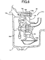
- FIG. 6 is a view showing, by way of example, a modification of the drive-force transmitting apparatus 12 to which the present invention is applied, wherein a part of the first oil pump P1 is modified.
- FIG. 6 is a cross sectional view corresponding to FIG. 3 and showing a structure for disposing a first oil pump P11 (that is a modification of the first oil pump P1) in the drive-force transmitting apparatus 12.
- a pump body 156 is fastened to the fastening portions 14a of the casing 14 by means of the fastening bolts 86.
- the pump body 156 includes a plurality of protruding portions 156a that protrude outwardly in the radial direction of the rotor 52.
- the plurality of protruding portions 156a consist of three protruding portions 156a that are substantially equi-angularly spaced apart from one another in a circumferential direction of the rotor 52, like the plurality of protruding portions 58a of the pump cover 58 of the first pump P1 in the above-described embodiment (see FIG. 2 ).
- the three protruding portions 156a cooperate with one another to constitute "outer peripheral portion (of the pump body)" recited in the appended claims, and correspond to "connected portions (that are included in the outer peripheral portion of the pump body)" recited in the appended claims.
- the pump body 156 further includes three non-protruding portions 156b each of which is located between a corresponding adjacent two of the three protruding portions 156a in the circumferential direction.
- a radial distance of each of the three protruding portions 156a from the axis C1 is larger than a radial distance of each of the non-protruding portions 156b from the axis C1, as shown in FIG.
- each of the protruding portions 156a of the pump body 156 is located on an outer side of an outer peripheral portion 158a of a pump cover 158 in the radial direction of the rotor 52.
- Each of the protruding portions 156a of the pump body 156 which radially outwardly protrude from the pump cover 158, has a bolt receiving hole 188 in which the fastening bolt 86 is received.
- the pump body 156 is fixed at the three protruding portions 156a to the fastening portions 14a of the casing 14 through the fastening bolts 86 which pass through the respective bolt receiving holes 188 and are screwed into the tapped holes provided in the fastening portions 14a.
- the modification of the embodiment shown in FIG. 6 provides substantially the same advantages as the above-described embodiment in which the pump cover 58 is fixed at the three protruding portions 58a to the fastening portions 14a of the casing 14 through the fastening bolts 86.
- the pump shaft 50 has the supported portion and the free end portion, such that the pump shaft 50 is rotatably supported at the supported portion by at least one of the pump body 56, 156 and the pump cover 58, 158, and such that the driven gear Gp is mounted on the free end portion of the pump shaft 50, wherein the pump body 56, 156 has the outer peripheral portion 56a, 156a that is located on the outer side of the other portion of the pump body 56, 156 in the radial direction of the rotor 52, and the pump cover 58, 158 has the outer peripheral portion 58a, 158a that is located on the outer side of the other portion of the pump cover 58, 158 in the radial direction, and wherein one of the outer peripheral portion 56a, 156a of the pump body 56, 156 and the outer peripheral portion 58a, 158a of the pump cover 58, 158 is supported by the casing 14, and the other portion of the pump body 56, 156 and
- the outer peripheral portion 56a, 156a of the pump body 56, 156 and the outer peripheral portion 58a, 158a of the pump cover 58, 158 are located on the outer side of the outer periphery of the rotor 52 in the radial direction. Owing to this arrangement, in the drive-force transmitting apparatus 12, it is possible to further increase the vibration transmission path from the vibration generating source of the first oil pump PI, P11 to the casing 14. Thus, it is possible to further damp the vibration generated in the rotor 52 or the meshing portions of the differential ring gear Gd and the driven gear Gp, and accordingly to further reduce the noise that is emitted to outside the casing 14.
- the pump shaft 50 is the stepped shaft having the first step 50d, wherein the rotor 52, which is mounted on the pump shaft 50, has the axially opposite end surfaces 52c, 52d that are opposite to each other in the axial direction of the pump shaft 50 (i.e., the direction of axis C1), such that one 52c of the axially opposite end surfaces 52c, 52d of the rotor 52, which is closer to the free end portion of the pump shaft 50 than the other 52d of the axially opposite end surfaces 52c, 52d, is in contact with the first step 50d of the pump shaft 50.
- movement of the rotor 52 relative to the pump shaft 50 in the axial direction is structurally limited, so that the rotor 52 can be positioned in a predetermined position relative to the pump shaft 50 in the axial direction, by a simple construction without an additional member such as a positioning member.
- the rotor 52 is limited, by the first step 50d of the pump shaft 50, from being displaced relative to the pump shaft 50 in the first direction that is parallel to the axial direction, wherein the driven gear Gp is the helical gear, and wherein, when the driven gear Gp is driven by the differential ring gear Gd during forward running of the vehicle 10, the thrust load Fs is applied to the driven gear Gp and acts in the second direction that is opposite to the first direction.
- the thrust load Fs is applied to the driven gear Gp as the helical gear in a direction in which the pump shaft 50 is introduced into the rotor 52, so that it is possible to reduce frequency of occurrence of a load forcing the pump shaft 50 to be removed from the rotor 52. Therefore, for fitting the pump shaft 50 into the rotor 52 or fitting the rotor 52 onto the pump shaft 50, an additional element such as a ball bearing and a bushing and an additional support structure for the casing 14 are not required, whereby the fitting of the rotor 52 and the pump shaft 50 can be made by a simplified construction.
- the pump body 56, 156 has the sliding contact surface 56d which is perpendicular to the axial direction and which is in sliding contact with the other 52d of the axially opposite end surfaces 52c, 52d of the rotor 52, wherein the thrust load Fs or a part of the thrust load Fs is received by the sliding contact surface 56d of the pump body 56, 156.
- the sliding contact surface 56d it is possible to cause the sliding contact surface 56d to cooperate or share with the pump shaft 50 to receive the thrust load Fs applied from the driven gear Gp, thereby making it possible to increase durability of the pump shaft 50.
- the pump body 56, 156 has the fluid inlet 64 and the fluid discharge passage 74 such that the fluid is introduced through the fluid inlet 64 from outside the pump body 56, 156 and such that the fluid is discharged through the fluid discharge passage 74 to outside the pump body 56, 156, wherein the second direction is substantially the same as the discharge direction in which the fluid flows to be discharged through the fluid discharge passage 74.
- the second direction i.e., the direction in which the thrust load Fs is applied from the driven gear Gp to the rotor 52, is opposite to a direction of the discharge reaction force Fr of the fluid discharged through the fluid discharge passage 74, so that the thrust load Fs applied from the driven gear Gp to the rotor 52 and the discharge reaction force Fr applied from the fluid to the rotor 52 can be offset by each other. Therefore, it is possible to reduce a surface pressure acting on the rotor 52 thereby leading to an improvement of durability of the rotor 52.
- At least a part of the fluid discharge passage 74 is located on an inner side of the outer periphery of the rotor 52 in the radial direction. Owing to this arrangement, the thrust load Fs applied from the driven gear Gp to the rotor 52 and the discharge reaction force Fr applied from the fluid to the rotor 52 can be more reliably offset by each other, thereby making it possible to more reliably reduce the surface pressure acting on the rotor 52 and to more reliably improve the durability of the rotor 52.
- the pump chamber 54 is defined in the pump body 56, 156.
- the pump chamber 54 may be defined in the pump cover 58, 158.
- the pump shat 50 is supported by both of the pump body 56, 156 and the pump cover 58, 158.
- the pump shaft 50 does not have to be supported necessarily by both of the pump body 56, 156 and the pump cover 58, 158, but may be supported by only one of the pump body 56, 156 and the pump cover 58, 158.
- the "protrusions" which are recited in the appended claims are constituted by the fastening portions 14a that are portions of the casing 14.
- the "protrusions” may be constituted by portions of the pump cover 58.
- the "protrusions” may be constituted by portions of the pump body 156.
Landscapes
- Engineering & Computer Science (AREA)
- General Engineering & Computer Science (AREA)
- Mechanical Engineering (AREA)
- Chemical & Material Sciences (AREA)
- Combustion & Propulsion (AREA)
- Transportation (AREA)
- Details And Applications Of Rotary Liquid Pumps (AREA)
- Rotary Pumps (AREA)
- Arrangement Of Transmissions (AREA)
- General Details Of Gearings (AREA)
Description
- The present invention relates to a drive-force transmitting apparatus for a vehicle, and is more particularly concerned with a structure for disposing a fluid pump in the drive-force transmitting apparatus.
- There is known a drive-force transmitting apparatus for a vehicle, wherein the transmitting apparatus includes: a drive gear that serves as a drive-force transmitting member configured to transmit a drive force from the drive force source to the drive wheels; a fluid pump that is to driven by rotation of the drive gear; and a casing that stores therein the drive gear and the fluid pump.
JP-2011-174583A - Further, in the drive-force transmitting apparatus disclosed in the above-identified Japanese Patent Application Publication, the fluid pump is in close contact with the casing so as to be attached to the casing, such that the pump cover is fitted in a recess provided in a wall surface of the casing. Owing to this arrangement, when the fluid pump is assembled into the casing, the rotor is prevented from being removed from the pump chamber whereby an assemblability of the fluid pump is improved.
- By the way, when the fluid pump is driven by the drive gear which serves as the drive-force transmitting member and which meshes with the driven gear mounted on the pump shaft, there is a case in which vibration is generated in the rotor or meshing portions of the respective drive and driven gears, due to a meshing transmission error (e.g., transmission error based on a rotational fluctuation of the drive or driven gear that is not rotated at a constant cycle). In the drive-force transmitting apparatus disclosed in the above-identified Japanese Patent Application Publication in which the entirety of a surface of the pump cover is in contact with the wall surface of the casing that is opposed to the surface of the pump cover, when the fluid pump is driven, the above-described vibration generated in the rotor or the meshing portions is transmitted, for example, through the pump cover, to the entirety of the wall surface of the casing whereby the casing is vibrated. Thus, the vibration is likely to be emitted as noise to outside the casing, so as to be transmitted to outside and/or inside the vehicle.
- The present invention was made in view of the background art described above. It is therefore an object of the present invention to provide a drive-force transmitting apparatus for a vehicle, which is capable of damping vibration generated by drive of a fluid pump, so as to reduce noise that is emitted to outside the casing.
- The object indicated above is achieved by a drive-force transmitting apparatus according to claim 1.
- According to a first aspect of the invention, there is provided a drive-force transmitting apparatus for a vehicle that includes a drive force source and drive wheels. The drive-force transmitting apparatus includes: a drive gear that serves as a drive-force transmitting member configured to transmit a drive force from the drive force source to the drive wheels; a fluid pump that is to driven by rotation of the drive gear; and a casing that stores therein the drive gear and the fluid pump. The fluid pump includes: a pump body that defines therein a pump chamber; a pump cover that covers the pump chamber and is fixed to the pump body; a rotor that is disposed in the pump chamber; a driven gear that meshes with the drive gear; and a pump shaft on which the rotor and the driven gear are mounted, wherein the pump shaft has a supported portion and a free end portion, such that the pump shaft is rotatably supported at the supported portion by at least one of the pump body and the pump cover, and such that the driven gear is mounted on the free end portion of the pump shaft, wherein the pump body has an outer peripheral portion that is located on an outer side of the pump body in a radial direction of the rotor, and the pump cover has an outer peripheral portion that is located on an outer side of the pump cover in the radial direction, and wherein one of the outer peripheral portion of the pump body and the outer peripheral portion of the pump cover is supported by the casing, and the rest of the pump body and the rest of the pump cover are spaced apart from the casing. For example, the pump shaft may be a cantilever shaft, and is may be rotatably supported by the pump body and the pump cover, such that the rotor is fitted on an end portion of the pump shaft while the driven gear is fitted on another end portion of the pump shaft. Further, the one of the outer peripheral portion of the pump body and the outer peripheral portion of the pump cover may include a plurality of connected portions that are connected to a plurality of connected portions of an inside wall surface of the casing through respective protrusions that extend between the plurality of connected portions of the above-described one and the plurality of connected portions of the inside wall surface, such that the rest of the pump body and the rest of the pump cover are spaced from at least a portion of the inside wall surface of the casing which is located between the plurality of connected portions of the inside wall surface of the casing. Moreover, the plurality of connected portions of the one of the outer peripheral portion of the pump body and the outer peripheral portion of the pump cover may consist of at least three connected portions, while the plurality of connected portions of the inside wall surface of the casing may consist of at least three connected portions, such that the portion of the inside wall surface of the casing, which is spaced apart from the rest of the pump body and the rest of the pump cover, is located between the at least three connected portions of the inside wall surface of the casing.
- According to a second aspect of the invention, in the drive-force transmitting apparatus according to the first aspect of the invention, the outer peripheral portion of the pump body and the outer peripheral portion of the pump cover are located on an outer side of an outer periphery of the rotor in the radial direction.
- According to a third aspect of the invention, in the drive-force transmitting apparatus according to the first or second aspect of the invention, the pump shaft is a stepped shaft having a step, wherein the rotor, which is mounted on the pump shaft, has axially opposite end surfaces that are opposite to each other in an axial direction of the pump shaft, such that one of the axially opposite end surfaces of the rotor, which is closer to the free end portion of the pump shaft than the other of the axially opposite end surfaces, is in contact with the step of the pump shaft.
- According to a fourth aspect of the invention, in the drive-force transmitting apparatus according to the third aspect of the invention, the rotor is limited, by the step of the pump shaft, from being displaced relative to the pump shaft in a first direction that is parallel to the axial direction, wherein the driven gear is a helical gear, and wherein, when the driven gear is driven by the drive gear during forward running of the vehicle, a thrust load is applied to the driven gear and acts in a second direction that is opposite to the first direction.
- According to a fifth aspect of the invention, in the drive-force transmitting apparatus according to the fourth aspect of the invention, the pump body has a sliding contact surface which is perpendicular to the axial direction and which is in sliding contact with the other of the axially opposite end surfaces of the rotor, wherein at least part of the thrust load is received by the sliding contact surface of the pump body.
- According to a sixth aspect of the invention, in the drive-force transmitting apparatus according to the fourth or fifth aspect of the invention, the pump body has a fluid inlet and a fluid discharge passage such that a fluid is introduced through the fluid inlet from outside the pump body and such that the fluid is discharged through the fluid discharge passage to outside the pump body, wherein the second direction is substantially the same as a discharge direction in which the fluid flows to be discharged through the fluid discharge passage.
- According to a seventh aspect of the invention, in the drive-force transmitting apparatus according to the sixth aspect of the invention, at least a part of the fluid discharge passage is located on an inner side of an outer periphery of the rotor in the radial direction.
- In the drive-force transmitting apparatus according to the first aspect of the invention, the pump shaft has the supported portion and the free end portion, such that the pump shaft is rotatably supported at the supported portion by at least one of the pump body and the pump cover, and such that the driven gear is mounted on the free end portion of the pump shaft, wherein the pump body has the outer peripheral portion that is located on the outer side of the other portion of the pump body in the radial direction of the rotor, and the pump cover has the outer peripheral portion that is located on the outer side of the other portion of the pump cover in the radial direction, and wherein one of the outer peripheral portion of the pump body and the outer peripheral portion of the pump cover is supported by the casing, and the rest of the pump body and the rest of the pump cover are spaced apart from the casing. Owing to this arrangement, in the drive-force transmitting apparatus, it is possible to increase a vibration transmission path from a vibration generating source of the fluid pump in the form of the rotor or meshing portions of the drive and driven gears, to the casing. Thus, it is possible to damp vibration generated in the rotor or the meshing portions of the drive and drive gears, and accordingly to reduce noise that is emitted to outside the casing.
- In the drive-force transmitting apparatus according to the second aspect of the invention, the outer peripheral portion of the pump body and the outer peripheral portion of the pump cover are located on the outer side of the outer periphery of the rotor in the radial direction. Owing to this arrangement, in the drive-force transmitting apparatus, it is possible to further increase the vibration transmission path from the vibration generating source of the fluid pump to the casing. Thus, it is possible to further damp the vibration generated in the rotor or the meshing portions of the drive and drive gears, and accordingly to further reduce the noise that is emitted to outside the casing.
- In the drive-force transmitting apparatus according to the third aspect of the invention, the pump shaft is the stepped shaft having the step, wherein the rotor, which is mounted on the pump shaft, has the axially opposite end surfaces that are opposite to each other in the axial direction of the pump shaft, such that one of the axially opposite end surfaces of the rotor, which is closer to the free end portion of the pump shaft than the other of the axially opposite end surfaces, is in contact with the step of the pump shaft. Owing to this arrangement, movement of the rotor relative to the pump shaft in the axial direction is structurally limited, so that the rotor can be positioned in a desired position relative to the pump shaft in the axial direction, by a simple construction without an additional member such as a positioning member.
- In the drive-force transmitting apparatus according to the fourth aspect of the invention, the rotor is limited, by the step of the pump shaft, from being displaced relative to the pump shaft in the first direction that is parallel to the axial direction, wherein the driven gear is the helical gear, and wherein, when the driven gear is driven by the drive gear during forward running of the vehicle, the thrust load is applied to the driven gear and acts in the second direction that is opposite to the first direction. Owing to this arrangement, during the forward running that is made frequently, the thrust load is applied to the driven gear as the helical gear in a direction in which the pump shaft is introduced into the rotor, so that it is possible to reduce frequency of occurrence of a load forcing the pump shaft to be removed from the rotor. Therefore, for fitting the pump shaft in the rotor or fitting the rotor on the pump shaft, an additional element such as a ball bearing and a bushing and an additional support structure for the casing are not required, whereby the fitting of the rotor and the pump shaft can be made by a simple construction.
- In the drive-force transmitting apparatus according to the fifth aspect of the invention, the pump body has the sliding contact surface which is perpendicular to the axial direction and which is in sliding contact with the other of the axially opposite end surfaces of the rotor, wherein the thrust load or a part of the thrust load is received by the sliding contact surface of the pump body. Owing to this arrangement, it is possible to cause the sliding contact surface to cooperate or share with the pump shaft to receive the thrust load applied from the driven gear, thereby making it possible to increase durability of the pump shaft.
- In the drive-force transmitting apparatus according to the sixth aspect of the invention, the pump body has the fluid inlet and the fluid discharge passage such that the fluid is introduced through the fluid inlet from outside the pump body and such that the fluid is discharged through the fluid discharge passage to outside the pump body, wherein the second direction is substantially the same as the discharge direction in which the fluid flows to be discharged through the fluid discharge passage. Owing to this arrangement, the second direction , i.e., the direction in which the thrust load is applied from the driven gear to the rotor, is opposite to a direction of a discharge reaction force of the fluid discharged through the fluid discharge passage, so that the thrust load applied from the driven gear to the rotor and the discharge reaction force applied from the fluid to the rotor can be offset by each other. Therefore, it is possible to reduce a surface pressure acting on the rotor thereby leading to an improvement of durability of the rotor.
- In the drive-force transmitting apparatus according to the seventh aspect of the invention, at least a part of the fluid discharge passage is located on an inner side of an outer periphery of the rotor in the radial direction. Owing to this arrangement, the thrust load applied from the driven gear to the rotor and the discharge reaction force applied from the fluid to the rotor can be more reliably offset by each other, thereby making it possible to more reliably reduce the surface pressure acting on the rotor and to more reliably improve the durability of the rotor.
-
-
FIG. 1 is a schematic view showing a drive-force transmitting apparatus for a vehicle, to which the present invention is applied; -
FIG. 2 is view showing, in enlargement, a part of the drive-force transmitting apparatus shown inFIG. 1 ; -
FIG. 3 is a cross sectional view taken in line III-III indicated inFIG. 2 and showing a structure for disposing a fluid pump in the drive-force transmitting apparatus shown inFIG. 1 ; -
FIG. 4 is a view showing, in enlargement, a part of the oil pump shown inFIG. 3 ; -
FIG. 5 is a view showing, in enlargement, the part of the oil pump shown inFIG. 3 ; and -
FIG. 6 is a view showing, by way of example, a modification of the drive-force transmitting apparatus to which the present invention is applied, wherein the oil pump is partially modified. - The present invention is applicable to a drive-force transmitting apparatus for any type of vehicle such as a vehicle which is to be driven by an internal combustion engine as a drive force source, a hybrid vehicle which has not only the engine but also an electric motor as another drive force source and which is to be driven by the engine and the electric motor, and an electric motor which has only an electric motor as a drive force source and which is to be driven by the electric motor. For example, the drive-force transmitting apparatus may be a transaxle that is to be installed in a FR (front engine - rear drive) vehicle or a four-wheel drive vehicle, or may be a transaxle of lateral installation type that is to be installed in a FF (front engine - front drive) vehicle such that a plurality of axes are arranged in parallel to a lateral (transverse) direction of the vehicle.
- Hereinafter, a preferred embodiment of the invention will be described in detail with reference to the accompanying drawings. The figures of the drawings are simplified or deformed as needed, and each portion is not necessarily precisely depicted in terms of dimension ratio, shape, etc.
-
FIG. 1 is a schematic view showing a transaxle, i.e., drive-force transmitting apparatus 12 for avehicle 10, to which the present invention is applied. The view ofFIG. 1 is a development view illustrating the drive-force transmitting apparatus 12 in a manner in which a plurality of axes of a drive-force transmitting mechanism 16 of the drive-force transmitting apparatus 12 are contained in a single plane. The drive-force transmitting apparatus 12 is configured to transmit an output of theengine 20 to right andleft drive wheels 38. The drive-force transmitting apparatus 12 is of a lateral installation type that is to be installed in a FF vehicle, for example, and a plurality of axes of the drive-force transmitting mechanism 16, which is disposed in thecasing 14, are arranged in parallel to a lateral direction of thevehicle 10. Theengine 20 is an internal combustion engine such as a gasoline engine or a diesel engine, which is configured to generate a drive force by combustion of a fuel. Thecasing 14 may be constituted by a single member or a plurality of members that are fixed to each other. - The drive-force transmitting mechanism 16 has first through fourth axes S1-S4 that substantially parallel to the lateral direction of the
vehicle 10. Aninput shaft 22 is disposed on the first axis S1, and is connected to theengine 20 serving as a drive force source for driving thevehicle 10. Aplanetary gear device 24 of a single-pinion type and a first motor generator MG1 are disposed to be coaxial with the first axis S1. Theplanetary gear device 24 and the first motor generator MG1 cooperate with each other to constitute an electrically-controlleddifferential portion 26. Theplanetary gear device 24, which constitutes a differential mechanism, has a first rotary element in the form of acarrier 24c that is connected to theinput shaft 22, a second rotary element in the form of asun gear 24s connected to the first motor generator MG1 and a third rotary element in the form of aring gear 24r provided integrally with an engine output gear Ge. The first motor generator MG1, which constitutes a differential-control rotating machine, is to be operated selectively as an electric motor and a generator. For example, in a regenerative control in which the first motor generator MG1 is operated as the generator, a rotational speed of thesun gear 24s is controlled in a continuously changing manner, whereby a rotational speed transmitted from theengine 20 is continuously changed and is outputted through the engine output gear Ge. Further, when a torque of the first motor generator MG1 is controlled to zero, thesun gear 24s is idled or freely rotated whereby transmission of the drive force between theengine 20 and the drive-force transmitting mechanism 16 is interrupted so that dragging of theengine 20 is prevented. - A large reduction gear Gr1 and a small reduction gear Gr2, which cooperate with each other to constitute a
reduction gear device 30, are mounted on respective axially opposite end portions of anintermediate shaft 28 that is disposed on the second axis S2. The large reduction gear Gr1 meshes with the above-described engine output gear Ge, and also with a motor output gear Gm of a second motor generator MG2 which is disposed on the third axis S3. The second motor generator MG2, which constitutes a vehicle-driving rotating machine, is to be operated selectively as an electric motor and a generator. For example, in a power running control in which the second motor generator MG2 is operated as the electric motor, the second motor generator MG2 serves as another drive force source for driving thevehicle 10. - The small reduction gear Gr2 meshes with a differential ring gear Gd of a
differential device 32 that is disponed on the fourth axis S4, so that the drive force transmitted from theengine 20 and/or the second motor generator MG2 is distributed to right and leftdrive axles 36 through thedifferential device 32 and is then transmitted to the right and leftdrive wheels 38. The differential ring gear Gd corresponds to "drive gear" recited in the appended claims. Thedifferential device 32 constitutes an output portion, and the differential ring gear Gd constitutes an input gear. The engine output gear Ge, large reduction gear Gr1, small reduction gear Gr2 and differential ring gear Gd cooperate with one another to constitute at least a part of a gear mechanism. - In the drive-
force transmitting apparatus 12 for thevehicle 10 according to the present invention, there are a first oil pump P1 and a second oil pump P2 as lubrication fluid sources of a lubricating device (not shown). The first and second oil pumps PI, P2 are connected to respective fluid supply passages that are independent from each other, so as to lubricate respective assigned parts of the drive-force transmitting mechanism 16. As shown inFIG. 1 , the first oil pump P1 is a mechanical pump that is to be mechanically driven through a driven gear Gp (described below) that meshes with a differential ring gear Gd (described below), while the second oil pump P2 is a mechanical pump that is connected to theinput shaft 22 so as to be mechanically driven through theengine 20. The first and second oil pumps PI, P2 are both disposed within thecasing 14. It is noted that the first oil pump P1 may be modified such that the first oil pump P1 is to be driven by adapting the driven gear Gp to mesh with the large reduction gear Gr1 or small reduction gear Gr2 that are rotatable with the differential ring gear Gd. -
FIG. 2 is view showing, in enlargement, a part of the drive-force transmitting apparatus 12 shown inFIG. 1 . Specifically,FIG. 2 shows a construction of a main portion of the first oil pump P1 and a surrounding of the main portion, namely, a positional relationship between the differential ring gear Gd and the driven gear Gp that mesh with each other, wherein the differential ring gear Gd serves as a drive-force transmitting member of the drive-force transmitting mechanism 16 and also as a drive gear for driving the first oil pump PI, while the driven gear Gp is an element included in the first oil pump P1.FIG. 3 is a cross sectional view taken in line III-III indicated inFIG. 2 . An upward direction inFIG. 3 corresponds to an upward direction of thevehicle 10, and a downward direction inFIG. 3 corresponds to a downward direction of thevehicle 10. Each ofFIGS. 4 and5 is a view showing, in enlargement, a part of the first oil pump P1 shown inFIG. 3 . The driven gear Gp of the first oil pump P1 meshes with the differential ring gear Gd provided in the drive-force transmitting mechanism 16, so that the first oil pump P1 is operated or driven with running of thevehicle 10. - The first oil pump P1 includes, in addition to the driven gear Gp meshing with the differential ring gear Gd, a
pump shaft 50 on which the driven gear Gp is mounted, arotor 52 mounted on thepump shaft 50, apump body 56 defining therein apump chamber 54, and apump cover 58 that is fixed to thepump body 56 so as to cover thepump chamber 54. Therotor 52 is disposed in thepump chamber 54. - The
pump shaft 50 extends in a direction of an axis C1 that corresponds to a horizontal direction ofFIG. 3 and penetrates through thepump body 56 and thepump cover 58. Thepump shaft 50 is a cantilever shaft having a free end portion and a supported portion, such that thepump shaft 50 is supported at the supported portion through plain or sliding bearings by thepump body 56 and thepump cover 58, so as to be rotatable about the axis C1. Thepump shaft 50 is a stepped shaft that is sectioned into a plurality of cylindrical portions which are arranged in the direction of the axis C1 and which have respective diameters that are different from each other, such that steps are present between the plurality of cylindrical portions. In the present embodiment, thepump shaft 50 is sectioned into three cylindrical portions having respective different diameters and coaxial with each other. Specifically, the three cylindrical portions consist of a firstcylindrical portion 50a having a diameter da, a secondcylindrical portion 50b contiguous to the firstcylindrical portion 50a and having a dimeter db larger than the diameter da, and a third cylindrical portion 50c contiguous to the secondcylindrical portion 50b and having a diameter dc smaller than the diameter db. The firstcylindrical portion 50a is located on a side of an axial end of thepump shaft 50, while the third cylindrical portion 50c is located on a side of another axial end of thepump shaft 50. The secondcylindrical portion 50b is located between the first and thirdcylindrical portions 50a, 50c in the direction of the axis C1. Therotor 52 is fitted on the firstcylindrical portion 50a so as to be unrotatable relative to thepump shaft 50. Each of the first and secondcylindrical portions pump shaft 50 is supported by thepump body 56 and thepump cover 58. The third cylindrical portion 50c constitutes the above-described free end portion on which the driven gear Gp is fitted on so as to be unrotatable relative to thepump shaft 50. Afirst step 50d is defined between the first and secondcylindrical portions second step 50e is defined between the second and thirdcylindrical portions 50b, 50c. - The
rotor 52, which is fitted on the firstcylindrical portion 50a unrotatably relative to thepump shaft 50, is an internal gear pump including aninner rotor 52a rotatable together with thepump shaft 50 about the axis C1 and anouter rotor 52b meshing with theinner rotor 52a and rotatable about an axis C2 that is offset from the axis C1. Each of the inner andouter rotors outer rotor 52b is disposed inside thepump chamber 54 defined in thepump body 56. Therotor 52, which is fitted on thepump shaft 50, has axially opposite end surfaces, and one 52c of the axiallyopposite end surfaces first step 50d, so that therotor 52 is limited, by thefirst step 50d, from being displaced relative to thepump shaft 50 in a leftward direction (as seen inFIG. 3 ) that is parallel to the direction of the axis C1. Thus, therotor 52 can be positioned in a predetermined position relative to thepump shaft 50 in the direction of the axis C1. With the driven gear Gp being rotated by rotation of the differential ring gear Gd, a hydraulic pressure is generated by rotation of therotor 52 together with thepump shaft 50 in the first oil pump P1. - The
pump body 56 is provided by a member that is elongated in a vertical direction, i.e., a height direction of thevehicle 10, and has afluid strainer 62 located in its lower end portion. Afluid inlet 64 is provided to open in a lower end of thefluid strainer 62. A lubricant fluid (oil), which is stored in a bottom portion of thecasing 14, is sucked up by rotation of therotor 52 and introduced into thefluid strainer 62 through thefluid inlet 64. On an upper side of thefluid inlet 64, afilter plate 66 is provided to filter the sucked lubricant fluid so as to remove foreign objects that are contained in the lubricant fluid. By thefilter plate 66, afilter chamber 68, which is provided by a space located on the upper side of thefluid inlet 64, is sectioned into two portions, i.e., upper and lower portions of thefilter chamber 68. In the present embodiment, thefluid strainer 62 is constituted by a member fixed to thepump body 56 and made from a plate that is formed to thefluid strainer 62 by, for example, a pressing operation. As shown inFIG. 3 , thefluid strainer 62 is fixed to an outerperipheral portion 56b of thepump body 56, which is provided by a lower end portion of thepump body 56, by suitable means such as caulking. - The
pump chamber 54, which is defined in thepump body 56, is located on an upper side of thefilter chamber 68, and is in communication with thefilter chamber 68 through afluid passage 70. Thepump chamber 54, which is in communication with thefluid passage 70, is defined by a hole having an opening that opens in a side surface of thepump body 56, which is opposed to thepump cover 58, such that therotor 52 can be introduced in thepump chamber 54 through the opening in a process of manufacturing the first oil pump P1. Therotor 52, which is disposed in thepump chamber 54, is in sliding contact at another one 52d of the above-described axiallyopposite end surfaces pump chamber 54 that corresponds to a slidingcontact surface 56d of thepump body 56, which is perpendicular to the axis C1. A through-hole 72 is provided to penetrate through a bottom wall of the above-described hole so as to extend in the direction of the axis C1 and open in the slidingcontact surface 56d of thepump chamber 54. The through-hole 72 receives therein the firstcylindrical portion 50a of thepump shaft 50. Thepump body 56 has a pump-shaft supporting portion 78 that defines the through-hole 72. The pump-shaft supporting portion 78 serves as a sliding bearing by which thepump shaft 50 is rotatably supported. It is noted that a sliding bearing member as an additional element may be provided to be fitted in the through-hole 72 so that thepump shaft 50 is rotatably supported by the pump-shaft supporting portion 78 through the sliding bearing member. - The
pump body 56 defines afluid discharge passage 74 that is located on an upper side of the through-hole 72, such that the lubricant fluid discharged from thepump chamber 54 is guided by thefluid discharge passage 74 toward outside thepump body 56, i.e., outside the first oil pump P1. Thefluid discharge passage 74, which is in communication with thepump chamber 54, has a tubular shape having an axis extending substantially in parallel to the axis C1 so that the lubricant fluid sucked through thefluid inlet 64 is discharged to flow in a direction substantially parallel to the axis C1. Afluid pipe 76 is fitted in thefluid discharge passage 74 so as to guide the discharged lubricant fluid toward desired parts of the drive-force transmitting mechanism 16 such as gears and bearings, which are required to be lubricated. Thefluid discharge passage 74 is positioned relative to therotor 52 such that at least portion of thefluid discharge passage 74 is located on an inner side of an outer periphery of therotor 52 in a radial direction of therotor 52, as shown inFIG. 3 . - The
pump cover 58 is fixed to thepump body 56 through fasteners in the form offastening bolts 80 that are shown inFIG. 2 . Thepump cover 58 is provided by a member that is elongated in the vertical direction of thevehicle 10, and is fixed to thepump body 56, such that thepump chamber 54 defined in thepump body 56 is covered by thepump cover 58. Thepump cover 58 has a through-hole 82 extending in the direction of the axis C1, and thepump shaft 50 passes through the through-hole 82. The through-hole 82 receives therein the secondcylindrical portion 50b of thepump shaft 50. Thepump cover 58 has a pump-shaft supporting portion 84 that defines the through-hole 82. The pump-shaft supporting portion 84 serves as a sliding bearing by which thepump shaft 50 is rotatably supported. Thus, thepump shaft 50 is rotatably supported at its supported portion by the pump-shaft supporting portions respective pump body 56 and pumpcover 58. It is noted that a sliding bearing member as an additional element may be provided to be fitted in the through-hole 82 so that thepump shaft 50 is rotatably supported by the pump-shaft supporting portion 84 through the sliding bearing member. - As shown in
FIGS. 2 and3 , thepump cover 58 includes a plurality of protrudingportions 58a that protrude outwardly in the radial direction of therotor 52. In the present embodiment, the plurality of protrudingportions 58a consist of three protrudingportions 58a that are substantially equi-angularly spaced apart from one another in a circumferential direction of therotor 52, as shown inFIG. 2 . The three protrudingportions 58a cooperate with one another to constitute "outer peripheral portion (of the pump cover)" recited in the appended claims, and correspond to "connected portions (that are included in the outer peripheral portion of the pump cover)" recited in the appended claims. The pump cover 58 further includes threenon-protruding portions 58b each of which is located between a corresponding adjacent two of the three protrudingportions 58a in the circumferential direction. A radial distance of each of the three protrudingportions 58a from the axis C1 is larger than a radial distance of each of thenon-protruding portions 58b from the axis C1, as shown inFIG. 3 that shows one of the three protrudingportions 58a that is located on an upper side of the axis C1 and one of thenon-protruding portions 58b that is located on a lower side of the axis C1. Further, as shown inFIG. 3 , each of the protrudingportions 58a of thepump cover 58 is located on an outer side of an outerperipheral portion 56a of thepump body 56 in the radial direction of therotor 52. Each of the protrudingportions 58a of thepump cover 58, which radially outwardly protrude from thepump body 56, has abolt receiving hole 88 in which afastening bolt 86 is received. Thepump cover 58 is fixed to threefastening portions 14a of thecasing 14 through thefastening bolts 86 which pass through the respectivebolt receiving holes 88 and are screwed into tapped holes provided in thefastening portions 14a. Each of thefastening portions 14a of thecasing 14 is constituted by a rib that protrudes from a corresponding one of three connectedportions 14c of aninside wall surface 14b of thecasing 14 toward inside thecasing 14 by a given distance. Each of thefastening portions 14a extends in a direction substantially parallel to the direction of the axis C1, from a corresponding one of the threeconnected portions 14c of theinside wall surface 14b, which are substantially equi-angularly spaced apart from one another in the circumferential direction of therotor 52. Each of thepump body 56 and thepump cover 58 is, for example, a die-cast member made of aluminum alloy. It is noted that thefastening portions 14a correspond to "protrusions" recited in the appended claims. - The driven gear Gp is fitted on the free end portion, i.e., the third cylindrical portion 50c of the
pump shaft 50, for example, by press-fitting, so as to be unrotatable relative to thepump shaft 50, so that the driven gear Gp is rotatable together with thepump shaft 50 about the axis C1. As shown inFIG. 3 , the driven gear Gp is located in a space S that is defined between theinside wall surface 14b of thecasing 14 and thepump cover 58. That is, thepump cover 58 is fastened to thefastening portions 14a that is constituted by the ribs that protrude from the respective connectedportions 14c of theinside wall surface 14b of thecasing 14 by the given distance, so that thepump cover 58 is distant from theinside wall surface 14b of thecasing 14, and the driven gear Gp is disposed in the space S that is defined between thepump cover 58 and theinside wall surface 14b of thecasing 14. - As shown in
FIGS. 4 and5 , when the first oil pump P1 is operated or driven with the driven gear Gp being driven by the differential ring gear Gd that meshes with the driven gear Gp, during forward running of thevehicle 10, a thrust load Fs, which is based on a meshing load generated between the differential ring gear Gd and the driven gear Gp which mesh with each other and which are helical gears, is applied to the driven gear Gp and acts in a direction of arrow A, as shown inFIGS. 4 and5 . InFIG. 4 , arrow B indicates a direction of a load Fsd that the slidingcontact surface 56d of thepump body 56 receives, wherein the load Fsd corresponds to the thrust load Fs or a part of the thrust load Fs, which is applied to the slidingcontact surface 56d through thepump shaft 50 and therotor 52, and arrow C indicates a direction in which therotor 52 is mounted onto thepump shaft 50 so as to be fitted on thepump shaft 50. Therotor 52 is limited, by thefirst step 50d of thepump shaft 50, from being displaced relative to thepump shaft 50, in the direction indicated by the arrow C. As shown inFIG. 4 , the first oil pump P1 is constructed such that, during forward running of thevehicle 10, the thrust load Fs, which is applied to or received by the driven gear Gp, acts in the direction of the arrow A that is opposite to the direction of the arrow C in which therotor 52 is limited from being displaced relative to thepump shaft 50. That is, during the forward running that is more frequent than a reverse running of thevehicle 10, the thrust load Fs is applied to the driven gear Gp as the helical gear in the direction of the arrow A, i.e., a direction in which thepump shaft 50 is introduced into therotor 52, so that it is possible to reduce frequency of occurrence of a load forcing thepump shaft 50 to be removed from therotor 52. - In
FIG. 5 , arrow D indicates a discharge direction in which the lubricant fluid flows to be discharged to outside thepump body 56 while being guided by thefluid discharge passage 74, and arrow E indicates a direction of a discharge pressure, i.e., a discharge reaction force Fr that is generated when the lubricant fluid sucked through thefluid inlet 64 is discharged through thefluid discharge passage 74 by operation of the first oil pump P1. That is, when the lubricant fluid is discharged to outside the first oil pump P1 by operation of the first oil pump PI, the discharge reaction force Fr is applied to therotor 52 through thepump body 56. Thus, the thrust load Fs and the discharge reaction force Fr act on therotor 52 in respective opposite directions that offset each other, so that it is possible to reduce a pressure acting on each of the axiallyopposite end surfaces rotor 52, for example. - Referring back to
FIG. 3 , two-dot chain line Vp indicates a vibration transmission path that is a path of transmission of vibration generated by meshing of the differential ring gear Gd and the driven gear Gp. In meshing portions of the differential ring gear Gd and the driven gear Gp, a so-called meshing transmission error, i.e., a transmission error based on a rotational fluctuation of the gears that are not rotated at a constant cycle, is generated, and the generation of the meshing transmission error causes vibration. Further, there is also a case in which the vibration is caused by driving of therotor 52. That is, when the first oil pump P1 is driven, the vibration is generated by a vibration generating source such as therotor 52 and the meshing portions of the differential ring gear Gd and the driven gear Gp. The vibration generated in the meshing portions of the gears Gd, Gp is transmitted to theinside wall surface 14b of thecasing 14, for example, via the driven gear Gp, thepump shaft 50 and thepump cover 58. The vibration generated in therotor 52 is transmitted to theinside wall surface 14b of thecasing 14, for example, via therotor 52, thepump shaft 50 and thepump cover 58. The vibration transmitted to thecasing 14 is emitted as noise to outside thecasing 14, so as to be transmitted to outside and/or inside thevehicle 10. However, the noise emitted to outside thecasing 14 can be reduced by damping the vibration with increase of the vibration transmission path Vp from the vibration generating source to theinside wall surface 14b of thecasing 14. In the present embodiment, the vibration transmission path Vp is longer than in an arrangement in which thepump shaft 50 is supported at an end portion by thepump body 56 and thepump cover 58 and is supported at another end portion by theinside wall surface 14b of thecasing 14 and an arrangement in which thepump body 56 and thepump cover 58 supporting thepump shaft 50 are in contact with theinside wall surface 14b of thecasing 14, so that the vibration is damped whereby the noise emitted to outside thecasing 14 is reduced. -
FIG. 6 is a view showing, by way of example, a modification of the drive-force transmitting apparatus 12 to which the present invention is applied, wherein a part of the first oil pump P1 is modified.FIG. 6 is a cross sectional view corresponding toFIG. 3 and showing a structure for disposing a first oil pump P11 (that is a modification of the first oil pump P1) in the drive-force transmitting apparatus 12. As shown inFIG. 6 , apump body 156 is fastened to thefastening portions 14a of thecasing 14 by means of thefastening bolts 86. - As shown in
FIG. 6 , thepump body 156 includes a plurality of protrudingportions 156a that protrude outwardly in the radial direction of therotor 52. Specifically, the plurality of protrudingportions 156a consist of three protrudingportions 156a that are substantially equi-angularly spaced apart from one another in a circumferential direction of therotor 52, like the plurality of protrudingportions 58a of thepump cover 58 of the first pump P1 in the above-described embodiment (seeFIG. 2 ). The three protrudingportions 156a cooperate with one another to constitute "outer peripheral portion (of the pump body)" recited in the appended claims, and correspond to "connected portions (that are included in the outer peripheral portion of the pump body)" recited in the appended claims. Thepump body 156 further includes threenon-protruding portions 156b each of which is located between a corresponding adjacent two of the three protrudingportions 156a in the circumferential direction. A radial distance of each of the three protrudingportions 156a from the axis C1 is larger than a radial distance of each of thenon-protruding portions 156b from the axis C1, as shown inFIG. 6 that shows one of the three protrudingportions 156a that is located on an upper side of the axis C1 and one of thenon-protruding portions 156b that is located on a lower side of the axis C1. Further, as shown inFIG. 6 , each of the protrudingportions 156a of thepump body 156 is located on an outer side of an outer peripheral portion 158a of apump cover 158 in the radial direction of therotor 52. Each of the protrudingportions 156a of thepump body 156, which radially outwardly protrude from thepump cover 158, has abolt receiving hole 188 in which thefastening bolt 86 is received. Thepump body 156 is fixed at the three protrudingportions 156a to thefastening portions 14a of thecasing 14 through thefastening bolts 86 which pass through the respectivebolt receiving holes 188 and are screwed into the tapped holes provided in thefastening portions 14a. The modification of the embodiment shown inFIG. 6 provides substantially the same advantages as the above-described embodiment in which thepump cover 58 is fixed at the three protrudingportions 58a to thefastening portions 14a of thecasing 14 through thefastening bolts 86. - In the drive-
force transmitting apparatus 12 according to the present embodiment and the modification, thepump shaft 50 has the supported portion and the free end portion, such that thepump shaft 50 is rotatably supported at the supported portion by at least one of thepump body pump cover pump shaft 50, wherein thepump body peripheral portion pump body rotor 52, and thepump cover peripheral portion 58a, 158a that is located on the outer side of the other portion of thepump cover peripheral portion pump body peripheral portion 58a, 158a of thepump cover casing 14, and the other portion of thepump body pump cover casing 14. Owing to this arrangement, in the drive-force transmitting apparatus 12, it is possible to increase a vibration transmission path from a vibration generating source of the first oil pump PI, P11 in the form of therotor 52 or meshing portions of the differential ring gear Gd and the driven gear Gp, to thecasing 14. Thus, it is possible to damp vibration generated in therotor 52 or the meshing portions of the differential ring gear Gd and the driven gear Gp, and accordingly to reduce noise that is emitted to outside thecasing 14. - In the drive-
force transmitting apparatus 12 according to the present embodiment and the modification, the outerperipheral portion pump body peripheral portion 58a, 158a of thepump cover rotor 52 in the radial direction. Owing to this arrangement, in the drive-force transmitting apparatus 12, it is possible to further increase the vibration transmission path from the vibration generating source of the first oil pump PI, P11 to thecasing 14. Thus, it is possible to further damp the vibration generated in therotor 52 or the meshing portions of the differential ring gear Gd and the driven gear Gp, and accordingly to further reduce the noise that is emitted to outside thecasing 14. - In the drive-
force transmitting apparatus 12 according to the present embodiment and the modification, thepump shaft 50 is the stepped shaft having thefirst step 50d, wherein therotor 52, which is mounted on thepump shaft 50, has the axiallyopposite end surfaces opposite end surfaces rotor 52, which is closer to the free end portion of thepump shaft 50 than the other 52d of the axiallyopposite end surfaces first step 50d of thepump shaft 50. Owing to this arrangement, movement of therotor 52 relative to thepump shaft 50 in the axial direction is structurally limited, so that therotor 52 can be positioned in a predetermined position relative to thepump shaft 50 in the axial direction, by a simple construction without an additional member such as a positioning member. - In the drive-
force transmitting apparatus 12 according to the present embodiment and the modification, therotor 52 is limited, by thefirst step 50d of thepump shaft 50, from being displaced relative to thepump shaft 50 in the first direction that is parallel to the axial direction, wherein the driven gear Gp is the helical gear, and wherein, when the driven gear Gp is driven by the differential ring gear Gd during forward running of thevehicle 10, the thrust load Fs is applied to the driven gear Gp and acts in the second direction that is opposite to the first direction. Owing to this arrangement, during the forward running that is made frequently, the thrust load Fs is applied to the driven gear Gp as the helical gear in a direction in which thepump shaft 50 is introduced into therotor 52, so that it is possible to reduce frequency of occurrence of a load forcing thepump shaft 50 to be removed from therotor 52. Therefore, for fitting thepump shaft 50 into therotor 52 or fitting therotor 52 onto thepump shaft 50, an additional element such as a ball bearing and a bushing and an additional support structure for thecasing 14 are not required, whereby the fitting of therotor 52 and thepump shaft 50 can be made by a simplified construction. - In the drive-
force transmitting apparatus 12 according to the present embodiment and the modification, thepump body contact surface 56d which is perpendicular to the axial direction and which is in sliding contact with the other 52d of the axiallyopposite end surfaces rotor 52, wherein the thrust load Fs or a part of the thrust load Fs is received by the slidingcontact surface 56d of thepump body contact surface 56d to cooperate or share with thepump shaft 50 to receive the thrust load Fs applied from the driven gear Gp, thereby making it possible to increase durability of thepump shaft 50. - In the drive-
force transmitting apparatus 12 according to the present embodiment and the modification, thepump body fluid inlet 64 and thefluid discharge passage 74 such that the fluid is introduced through thefluid inlet 64 from outside thepump body fluid discharge passage 74 to outside thepump body fluid discharge passage 74. Owing to this arrangement, the second direction , i.e., the direction in which the thrust load Fs is applied from the driven gear Gp to therotor 52, is opposite to a direction of the discharge reaction force Fr of the fluid discharged through thefluid discharge passage 74, so that the thrust load Fs applied from the driven gear Gp to therotor 52 and the discharge reaction force Fr applied from the fluid to therotor 52 can be offset by each other. Therefore, it is possible to reduce a surface pressure acting on therotor 52 thereby leading to an improvement of durability of therotor 52. - In the drive-
force transmitting apparatus 12 according to the present embodiment and the modification, at least a part of thefluid discharge passage 74 is located on an inner side of the outer periphery of therotor 52 in the radial direction. Owing to this arrangement, the thrust load Fs applied from the driven gear Gp to therotor 52 and the discharge reaction force Fr applied from the fluid to therotor 52 can be more reliably offset by each other, thereby making it possible to more reliably reduce the surface pressure acting on therotor 52 and to more reliably improve the durability of therotor 52. - While the preferred embodiment of this invention and the modification have been described in detail by reference to the drawings, it is to be understood that the invention may be otherwise embodied.
- For example, in the above-described embodiment and modification, the
pump chamber 54 is defined in thepump body pump chamber 54 may be defined in thepump cover pump body pump cover pump shaft 50 does not have to be supported necessarily by both of thepump body pump cover pump body pump cover fastening portions 14a that are portions of thecasing 14. However, in the above-described embodiment, the "protrusions" may be constituted by portions of thepump cover 58. Similarly, in the above-described modification, the "protrusions" may be constituted by portions of thepump body 156. - It is to be understood that the embodiment described above is given for illustrative purpose only, and that the present invention may be embodied with various modifications and improvements which may occur to those skilled in the art.
-
- 10: vehicle
- 12: drive-force transmitting apparatus
- 14: casing
- 16: drive-force transmitting mechanism
- 20: engine (drive force source)
- 38: drive wheels
- 50: pump shaft
- 50d: first step (step)
- 52: rotor
- 52c, 52d: axially opposite end surfaces
- 54: pump chamber
- 56: pump body
- 56a: outer peripheral portion
- 56d: sliding contact surface
- 58: pump cover
- 58a: outer peripheral portion
- 64: fluid inlet
- 74: fluid discharge passage
- PI: first oil pump (fluid pump)
- Gp: driven gear
- Gd: differential ring gear (drive-force transmitting member, drive gear)
- S: space
Claims (9)
- A drive-force transmitting apparatus (12) for a vehicle (10) that includes a drive force source (20) and drive wheels (38), said drive-force transmitting apparatus (12) comprising:a drive gear (Gd) that serves as a drive-force transmitting member (Gd) configured to transmit a drive force from the drive force source (20) to the drive wheels (38);a fluid pump (PI; P11) that is to driven by rotation of said drive gear (Gd); anda casing (14) that stores therein said drive gear (Gd) and said fluid pump (PI; P11),wherein said fluid pump (PI; P11) includes:a pump body (56; 156) that defines therein a pump chamber (54);a pump cover (58; 158) that covers said pump chamber (54) and is fixed to said pump body (56; 156);a rotor (52) that is disposed in said pump chamber (54);a driven gear (Gp) that meshes with said drive gear (Gd); anda pump shaft (50) on which said rotor (52) and said driven gear (Gp) are mounted,wherein said pump shaft (50) has a supported portion (50a, 50b) and a free end portion (50c), such that said pump shaft (50) is rotatably supported at said supported portion (50a, 50b) by at least one of said pump body (56; 156) and said pump cover (58; 158), and such that said driven gear (Gp) is mounted on said free end portion (50c) of said pump shaft (50),wherein said pump body (56; 156) has an outer peripheral portion (56a; 156a) that is located on an outer side of said pump body (56; 156) in a radial direction of said rotor (52), and said pump cover (58; 158) has an outer peripheral portion (58a; 158a) that is located on an outer side of said pump cover (58; 158) in said radial direction,wherein one (58a; 156a) of said outer peripheral portion (56a; 156a) of said pump body (56; 156) and said outer peripheral portion (58a; 158a) of said pump cover (58; 158) is supported by said casing (14), and the rest of said pump body (56; 156) and the rest of said pump cover (58; 158) are spaced apart from said casing (14), andwherein said outer peripheral portion (56a; 156a) of said pump body (56; 156) and said outer peripheral portion (58a; 158a) of said pump cover (58; 158) are located on an outer side of an outer periphery of said rotor (52) in said radial direction.
- The drive-force transmitting apparatus (12) according to claim 1,
wherein said pump shaft (50) is a stepped shaft (50) having a step (50d), and
wherein said rotor (52), which is mounted on said pump shaft (50), has axially opposite end surfaces that are opposite to each other in an axial direction of said pump shaft (50), such that one (52c) of said axially opposite end surfaces of said rotor (52), which is closer to said free end portion (50c) of said pump shaft (50) than the other (52d) of said axially opposite end surfaces, is in contact with said step (50d) of said pump shaft (50). - The drive-force transmitting apparatus (12) according to claim 2,
wherein said rotor (52) is limited, by said step (50d) of said pump shaft (50), from being displaced relative to said pump shaft (50) in a first direction (C) that is parallel to said axial direction,
wherein said driven gear (Gp) is a helical gear (Gp), and
wherein, when said driven gear (Gp) is driven by said drive gear (Gd) during forward running of the vehicle (10), a thrust load is applied to said driven gear (Gp) and acts in a second direction (A) that is opposite to the first direction (C). - The drive-force transmitting apparatus (12) according to claim 3,
wherein said pump body (56; 156) has a sliding contact surface (56d) which is perpendicular to said axial direction and which is in sliding contact with said other (52d) of said axially opposite end surfaces of said rotor (52), and
wherein at least a part of said thrust load is received by said sliding contact surface (56d) of said pump body (56; 156). - The drive-force transmitting apparatus (12) according to claim 3 or 4,
wherein said pump body (56; 156) has a fluid inlet (64) and a fluid discharge passage (74) such that a fluid is introduced through said fluid inlet (64) from outside said pump body (56; 156) and such that the fluid is discharged through said fluid discharge passage (74) to outside said pump body (56; 156), and
wherein said second direction (A) is substantially the same as a discharge direction (D) in which the fluid flows to be discharged through said fluid discharge passage (74). - The drive-force transmitting apparatus (12) according to claim 5,
wherein at least a part of said fluid discharge passage (74) is located on an inner side of an outer periphery of said rotor (52) in said radial direction. - The drive-force transmitting apparatus (12) according to any one of claims 1-6,
wherein said pump shaft (50) is a cantilever shaft (50), and is rotatably supported by said pump body (56; 156) and said pump cover (58; 158),
wherein said rotor (52) is fitted on an end portion (50a) of said pump shaft (50) while said driven gear (Gp) is fitted on another end portion (50c) of said pump shaft (50). - The drive-force transmitting apparatus (12) according to any one of claims 1-7,
wherein said one (58a; 156a) of said outer peripheral portion (56a; 156a) of said pump body (56; 156) and said outer peripheral portion (58a; 158a) of said pump cover (58; 158) includes a plurality of connected portions (58a; 156a) that are connected to a plurality of connected portions (14c) of an inside wall surface (14b) of said casing (14) through respective protrusions (14a) that extend between said plurality of connected portions (58a; 156a) of said one (58a; 156a) and said plurality of connected portions (14c) of said inside wall surface (14b), and
wherein the rest of said pump body (56; 156) and the rest of said pump cover (58; 158) are spaced from at least a portion of said inside wall surface (14b) of said casing (14) which is located between said plurality of connected portions (14c) of said inside wall surface (14b) of said casing (14). - The drive-force transmitting apparatus (12) according to claim 8,
wherein said plurality of connected portions (58a; 156a) of said one (58a; 156a) of said outer peripheral portion (56a; 156a) of said pump body (56; 156) and said outer peripheral portion (58a; 158a) of said pump cover (58; 158) consist of at least three connected portions (58a; 156a),
wherein said plurality of connected portions (14c) of said inside wall surface (14b) of said casing (14) consist of at least three connected portions (14c), and
wherein said portion of said inside wall surface (14b) of said casing (14), which is spaced apart from the rest of said pump body (56; 156) and the rest of said pump cover (58; 158), is located between said at least three connected portions (14c) of said inside wall surface (14b) of said casing (14).
Applications Claiming Priority (1)
| Application Number | Priority Date | Filing Date | Title |
|---|---|---|---|
| JP2018129347A JP7070174B2 (en) | 2018-07-06 | 2018-07-06 | Vehicle power transmission device |
Publications (2)
| Publication Number | Publication Date |
|---|---|
| EP3628893A1 EP3628893A1 (en) | 2020-04-01 |
| EP3628893B1 true EP3628893B1 (en) | 2021-05-19 |
Family
ID=67437540
Family Applications (1)
| Application Number | Title | Priority Date | Filing Date |
|---|---|---|---|
| EP19184629.4A Active EP3628893B1 (en) | 2018-07-06 | 2019-07-05 | Drive-force transmitting apparatus for vehicle |
Country Status (4)
| Country | Link |
|---|---|
| US (1) | US10967845B2 (en) |
| EP (1) | EP3628893B1 (en) |
| JP (1) | JP7070174B2 (en) |
| CN (1) | CN110685898B (en) |
Families Citing this family (4)
| Publication number | Priority date | Publication date | Assignee | Title |
|---|---|---|---|---|
| CN110388450B (en) * | 2018-04-20 | 2023-07-04 | 丰田自动车株式会社 | Lubrication device for power transmission unit |
| US10975955B2 (en) * | 2018-08-24 | 2021-04-13 | Dana Automotive Systems Group, Llc | Planetary gear system |
| JP2021148056A (en) * | 2020-03-18 | 2021-09-27 | 株式会社アイシン | Oil pump device |
| DE102021116160A1 (en) * | 2021-06-22 | 2022-12-22 | Fte Automotive Gmbh | Gear pump and prime mover |
Family Cites Families (14)
| Publication number | Priority date | Publication date | Assignee | Title |
|---|---|---|---|---|
| US6413183B1 (en) * | 1999-04-14 | 2002-07-02 | Tochigi Fuji Sangyo Kabushiki Kaisha | Power transmission apparatus |
| JP4427700B2 (en) * | 2000-09-13 | 2010-03-10 | アイシン・エィ・ダブリュ株式会社 | Hybrid drive unit |
| US6855083B1 (en) * | 2001-01-18 | 2005-02-15 | Dana Corporation | Lubrication pump for inter-axle differential |
| JP5064886B2 (en) * | 2007-05-21 | 2012-10-31 | 株式会社Tbk | Gear pump |
| JP4676515B2 (en) | 2008-07-11 | 2011-04-27 | ジヤトコ株式会社 | Support structure of cylindrical member in automatic transmission mechanism |
| EP2325525B1 (en) * | 2009-10-30 | 2013-03-27 | Kanzaki Kokyukoki Mfg. Co., Ltd. | Transmission |
| DE112010003293B4 (en) * | 2009-11-19 | 2016-05-04 | Aisin Aw Co., Ltd. | Drive device for a vehicle |
| FR2956460B1 (en) | 2010-02-17 | 2012-05-25 | Peugeot Citroen Automobiles Sa | TRANSMISSION DEVICE EQUIPPED WITH A LUBRICATION FLUID PUMP. |
| JP2011174583A (en) | 2010-02-25 | 2011-09-08 | Toyota Motor Corp | Vehicle power transmission device |
| JP4981152B2 (en) * | 2010-04-20 | 2012-07-18 | トヨタ自動車株式会社 | Vehicle oil pump |
| JP5297429B2 (en) * | 2010-09-24 | 2013-09-25 | アイシン・エィ・ダブリュ株式会社 | Hydraulic pressure generator and drive device |
| JP5835808B2 (en) | 2012-07-09 | 2015-12-24 | 本田技研工業株式会社 | Oil pump support structure |
| JP6904214B2 (en) * | 2017-10-27 | 2021-07-14 | トヨタ自動車株式会社 | Vehicle drive |
| JP6923466B2 (en) * | 2018-02-09 | 2021-08-18 | トヨタ自動車株式会社 | Vehicle drive |
-
2018
- 2018-07-06 JP JP2018129347A patent/JP7070174B2/en active Active
-
2019
- 2019-06-24 US US16/449,877 patent/US10967845B2/en active Active
- 2019-07-04 CN CN201910599885.4A patent/CN110685898B/en active Active
- 2019-07-05 EP EP19184629.4A patent/EP3628893B1/en active Active
Non-Patent Citations (1)
| Title |
|---|
| None * |
Also Published As
| Publication number | Publication date |
|---|---|
| US10967845B2 (en) | 2021-04-06 |
| US20200010072A1 (en) | 2020-01-09 |
| JP2020006791A (en) | 2020-01-16 |
| JP7070174B2 (en) | 2022-05-18 |
| EP3628893A1 (en) | 2020-04-01 |
| CN110685898B (en) | 2021-08-06 |
| CN110685898A (en) | 2020-01-14 |
Similar Documents
| Publication | Publication Date | Title |
|---|---|---|
| EP3628893B1 (en) | Drive-force transmitting apparatus for vehicle | |
| CN108237893B (en) | Hybrid vehicle and lubrication structure for hybrid vehicle | |
| US8746405B2 (en) | Variable lubricant level in a differential sump | |
| JP4981152B2 (en) | Vehicle oil pump | |
| CN102596617B (en) | Electric motors for electric axles of motor vehicles | |
| JP2011174582A (en) | Vehicular power transmission device | |
| US20160146332A1 (en) | Driving system for vehicle | |
| CN114375375B (en) | transmission | |
| EP1403558A2 (en) | Lubricating oil supply structure in a planetary transmission | |
| JP2009257494A (en) | Motor drive unit and in-wheel motor drive unit | |
| CN114450506B (en) | transmission | |
| CN110159740A (en) | Power transmission | |
| CN100385145C (en) | Automatic Transmission | |
| JPS6140862B2 (en) | ||
| CN112576732B (en) | Vehicle drive device | |
| JP7407074B2 (en) | Hybrid vehicle drive system | |
| US12188553B1 (en) | Automotive drivetrain gearbox including differential housing including fluid flow holes | |
| CN114423968B (en) | transmission | |
| US12169016B1 (en) | Automotive drivetrain gearbox including differential cover nested with rotor | |
| CN121273864A (en) | Differential device and drive transmission device | |
| US11708888B2 (en) | Shaft for a motor vehicle transmission | |
| JP2018123934A (en) | Lubrication structure of power transmission device | |
| JPS6327595B2 (en) | ||
| JPH08200478A (en) | Lubricating structure for gear transmission | |
| JP2001221264A (en) | Coupling |
Legal Events
| Date | Code | Title | Description |
|---|---|---|---|
| PUAI | Public reference made under article 153(3) epc to a published international application that has entered the european phase |
Free format text: ORIGINAL CODE: 0009012 |
|
| STAA | Information on the status of an ep patent application or granted ep patent |
Free format text: STATUS: REQUEST FOR EXAMINATION WAS MADE |
|
| 17P | Request for examination filed |
Effective date: 20190719 |
|
| AK | Designated contracting states |
Kind code of ref document: A1 Designated state(s): AL AT BE BG CH CY CZ DE DK EE ES FI FR GB GR HR HU IE IS IT LI LT LU LV MC MK MT NL NO PL PT RO RS SE SI SK SM TR |
|
| AX | Request for extension of the european patent |
Extension state: BA ME |
|
| GRAP | Despatch of communication of intention to grant a patent |
Free format text: ORIGINAL CODE: EPIDOSNIGR1 |
|
| STAA | Information on the status of an ep patent application or granted ep patent |
Free format text: STATUS: GRANT OF PATENT IS INTENDED |
|
| INTG | Intention to grant announced |
Effective date: 20201211 |
|
| RIN1 | Information on inventor provided before grant (corrected) |
Inventor name: KIYOKAMI, HIROAKI Inventor name: IWAKURA, KAZUKI |
|
| GRAS | Grant fee paid |
Free format text: ORIGINAL CODE: EPIDOSNIGR3 |
|
| GRAA | (expected) grant |
Free format text: ORIGINAL CODE: 0009210 |
|
| STAA | Information on the status of an ep patent application or granted ep patent |
Free format text: STATUS: THE PATENT HAS BEEN GRANTED |
|
| AK | Designated contracting states |
Kind code of ref document: B1 Designated state(s): AL AT BE BG CH CY CZ DE DK EE ES FI FR GB GR HR HU IE IS IT LI LT LU LV MC MK MT NL NO PL PT RO RS SE SI SK SM TR |
|
| REG | Reference to a national code |
Ref country code: GB Ref legal event code: FG4D |
|
| REG | Reference to a national code |
Ref country code: CH Ref legal event code: EP |
|
| REG | Reference to a national code |
Ref country code: DE Ref legal event code: R096 Ref document number: 602019004664 Country of ref document: DE |
|
| REG | Reference to a national code |
Ref country code: AT Ref legal event code: REF Ref document number: 1394278 Country of ref document: AT Kind code of ref document: T Effective date: 20210615 |
|
| REG | Reference to a national code |
Ref country code: IE Ref legal event code: FG4D |
|
| REG | Reference to a national code |
Ref country code: LT Ref legal event code: MG9D |
|
| REG | Reference to a national code |
Ref country code: AT Ref legal event code: MK05 Ref document number: 1394278 Country of ref document: AT Kind code of ref document: T Effective date: 20210519 |
|
| REG | Reference to a national code |
Ref country code: NL Ref legal event code: MP Effective date: 20210519 |
|
| PG25 | Lapsed in a contracting state [announced via postgrant information from national office to epo] |
Ref country code: AT Free format text: LAPSE BECAUSE OF FAILURE TO SUBMIT A TRANSLATION OF THE DESCRIPTION OR TO PAY THE FEE WITHIN THE PRESCRIBED TIME-LIMIT Effective date: 20210519 Ref country code: BG Free format text: LAPSE BECAUSE OF FAILURE TO SUBMIT A TRANSLATION OF THE DESCRIPTION OR TO PAY THE FEE WITHIN THE PRESCRIBED TIME-LIMIT Effective date: 20210819 Ref country code: FI Free format text: LAPSE BECAUSE OF FAILURE TO SUBMIT A TRANSLATION OF THE DESCRIPTION OR TO PAY THE FEE WITHIN THE PRESCRIBED TIME-LIMIT Effective date: 20210519 Ref country code: LT Free format text: LAPSE BECAUSE OF FAILURE TO SUBMIT A TRANSLATION OF THE DESCRIPTION OR TO PAY THE FEE WITHIN THE PRESCRIBED TIME-LIMIT Effective date: 20210519 Ref country code: HR Free format text: LAPSE BECAUSE OF FAILURE TO SUBMIT A TRANSLATION OF THE DESCRIPTION OR TO PAY THE FEE WITHIN THE PRESCRIBED TIME-LIMIT Effective date: 20210519 |
|
| PG25 | Lapsed in a contracting state [announced via postgrant information from national office to epo] |
Ref country code: PT Free format text: LAPSE BECAUSE OF FAILURE TO SUBMIT A TRANSLATION OF THE DESCRIPTION OR TO PAY THE FEE WITHIN THE PRESCRIBED TIME-LIMIT Effective date: 20210920 Ref country code: SE Free format text: LAPSE BECAUSE OF FAILURE TO SUBMIT A TRANSLATION OF THE DESCRIPTION OR TO PAY THE FEE WITHIN THE PRESCRIBED TIME-LIMIT Effective date: 20210519 Ref country code: RS Free format text: LAPSE BECAUSE OF FAILURE TO SUBMIT A TRANSLATION OF THE DESCRIPTION OR TO PAY THE FEE WITHIN THE PRESCRIBED TIME-LIMIT Effective date: 20210519 Ref country code: NO Free format text: LAPSE BECAUSE OF FAILURE TO SUBMIT A TRANSLATION OF THE DESCRIPTION OR TO PAY THE FEE WITHIN THE PRESCRIBED TIME-LIMIT Effective date: 20210819 Ref country code: LV Free format text: LAPSE BECAUSE OF FAILURE TO SUBMIT A TRANSLATION OF THE DESCRIPTION OR TO PAY THE FEE WITHIN THE PRESCRIBED TIME-LIMIT Effective date: 20210519 Ref country code: PL Free format text: LAPSE BECAUSE OF FAILURE TO SUBMIT A TRANSLATION OF THE DESCRIPTION OR TO PAY THE FEE WITHIN THE PRESCRIBED TIME-LIMIT Effective date: 20210519 Ref country code: GR Free format text: LAPSE BECAUSE OF FAILURE TO SUBMIT A TRANSLATION OF THE DESCRIPTION OR TO PAY THE FEE WITHIN THE PRESCRIBED TIME-LIMIT Effective date: 20210820 Ref country code: IS Free format text: LAPSE BECAUSE OF FAILURE TO SUBMIT A TRANSLATION OF THE DESCRIPTION OR TO PAY THE FEE WITHIN THE PRESCRIBED TIME-LIMIT Effective date: 20210919 |
|
| PG25 | Lapsed in a contracting state [announced via postgrant information from national office to epo] |
Ref country code: NL Free format text: LAPSE BECAUSE OF FAILURE TO SUBMIT A TRANSLATION OF THE DESCRIPTION OR TO PAY THE FEE WITHIN THE PRESCRIBED TIME-LIMIT Effective date: 20210519 |
|
| PG25 | Lapsed in a contracting state [announced via postgrant information from national office to epo] |
Ref country code: EE Free format text: LAPSE BECAUSE OF FAILURE TO SUBMIT A TRANSLATION OF THE DESCRIPTION OR TO PAY THE FEE WITHIN THE PRESCRIBED TIME-LIMIT Effective date: 20210519 Ref country code: ES Free format text: LAPSE BECAUSE OF FAILURE TO SUBMIT A TRANSLATION OF THE DESCRIPTION OR TO PAY THE FEE WITHIN THE PRESCRIBED TIME-LIMIT Effective date: 20210519 Ref country code: SK Free format text: LAPSE BECAUSE OF FAILURE TO SUBMIT A TRANSLATION OF THE DESCRIPTION OR TO PAY THE FEE WITHIN THE PRESCRIBED TIME-LIMIT Effective date: 20210519 Ref country code: CZ Free format text: LAPSE BECAUSE OF FAILURE TO SUBMIT A TRANSLATION OF THE DESCRIPTION OR TO PAY THE FEE WITHIN THE PRESCRIBED TIME-LIMIT Effective date: 20210519 Ref country code: DK Free format text: LAPSE BECAUSE OF FAILURE TO SUBMIT A TRANSLATION OF THE DESCRIPTION OR TO PAY THE FEE WITHIN THE PRESCRIBED TIME-LIMIT Effective date: 20210519 Ref country code: RO Free format text: LAPSE BECAUSE OF FAILURE TO SUBMIT A TRANSLATION OF THE DESCRIPTION OR TO PAY THE FEE WITHIN THE PRESCRIBED TIME-LIMIT Effective date: 20210519 Ref country code: SM Free format text: LAPSE BECAUSE OF FAILURE TO SUBMIT A TRANSLATION OF THE DESCRIPTION OR TO PAY THE FEE WITHIN THE PRESCRIBED TIME-LIMIT Effective date: 20210519 |
|
| REG | Reference to a national code |
Ref country code: DE Ref legal event code: R097 Ref document number: 602019004664 Country of ref document: DE |
|
| PLBE | No opposition filed within time limit |
Free format text: ORIGINAL CODE: 0009261 |
|
| STAA | Information on the status of an ep patent application or granted ep patent |
Free format text: STATUS: NO OPPOSITION FILED WITHIN TIME LIMIT |
|
| PG25 | Lapsed in a contracting state [announced via postgrant information from national office to epo] |
Ref country code: MC Free format text: LAPSE BECAUSE OF FAILURE TO SUBMIT A TRANSLATION OF THE DESCRIPTION OR TO PAY THE FEE WITHIN THE PRESCRIBED TIME-LIMIT Effective date: 20210519 |
|
| REG | Reference to a national code |
Ref country code: BE Ref legal event code: MM Effective date: 20210731 |
|
| 26N | No opposition filed |
Effective date: 20220222 |
|
| PG25 | Lapsed in a contracting state [announced via postgrant information from national office to epo] |
Ref country code: IS Free format text: LAPSE BECAUSE OF FAILURE TO SUBMIT A TRANSLATION OF THE DESCRIPTION OR TO PAY THE FEE WITHIN THE PRESCRIBED TIME-LIMIT Effective date: 20210919 Ref country code: LU Free format text: LAPSE BECAUSE OF NON-PAYMENT OF DUE FEES Effective date: 20210705 Ref country code: AL Free format text: LAPSE BECAUSE OF FAILURE TO SUBMIT A TRANSLATION OF THE DESCRIPTION OR TO PAY THE FEE WITHIN THE PRESCRIBED TIME-LIMIT Effective date: 20210519 |
|
| PG25 | Lapsed in a contracting state [announced via postgrant information from national office to epo] |
Ref country code: IT Free format text: LAPSE BECAUSE OF FAILURE TO SUBMIT A TRANSLATION OF THE DESCRIPTION OR TO PAY THE FEE WITHIN THE PRESCRIBED TIME-LIMIT Effective date: 20210519 Ref country code: IE Free format text: LAPSE BECAUSE OF NON-PAYMENT OF DUE FEES Effective date: 20210705 Ref country code: BE Free format text: LAPSE BECAUSE OF NON-PAYMENT OF DUE FEES Effective date: 20210731 |
|
| PGFP | Annual fee paid to national office [announced via postgrant information from national office to epo] |
Ref country code: FR Payment date: 20220510 Year of fee payment: 4 |
|
| REG | Reference to a national code |
Ref country code: CH Ref legal event code: PL |
|
| PG25 | Lapsed in a contracting state [announced via postgrant information from national office to epo] |
Ref country code: LI Free format text: LAPSE BECAUSE OF NON-PAYMENT OF DUE FEES Effective date: 20220731 Ref country code: CH Free format text: LAPSE BECAUSE OF NON-PAYMENT OF DUE FEES Effective date: 20220731 |
|
| P01 | Opt-out of the competence of the unified patent court (upc) registered |
Effective date: 20230427 |
|
| REG | Reference to a national code |
Ref country code: DE Ref legal event code: R084 Ref document number: 602019004664 Country of ref document: DE |
|
| PG25 | Lapsed in a contracting state [announced via postgrant information from national office to epo] |
Ref country code: CY Free format text: LAPSE BECAUSE OF FAILURE TO SUBMIT A TRANSLATION OF THE DESCRIPTION OR TO PAY THE FEE WITHIN THE PRESCRIBED TIME-LIMIT Effective date: 20210519 |
|
| PG25 | Lapsed in a contracting state [announced via postgrant information from national office to epo] |
Ref country code: HU Free format text: LAPSE BECAUSE OF FAILURE TO SUBMIT A TRANSLATION OF THE DESCRIPTION OR TO PAY THE FEE WITHIN THE PRESCRIBED TIME-LIMIT; INVALID AB INITIO Effective date: 20190705 |
|
| GBPC | Gb: european patent ceased through non-payment of renewal fee |
Effective date: 20230705 |
|
| PG25 | Lapsed in a contracting state [announced via postgrant information from national office to epo] |
Ref country code: MK Free format text: LAPSE BECAUSE OF FAILURE TO SUBMIT A TRANSLATION OF THE DESCRIPTION OR TO PAY THE FEE WITHIN THE PRESCRIBED TIME-LIMIT Effective date: 20210519 Ref country code: GB Free format text: LAPSE BECAUSE OF NON-PAYMENT OF DUE FEES Effective date: 20230705 |
|
| PG25 | Lapsed in a contracting state [announced via postgrant information from national office to epo] |
Ref country code: FR Free format text: LAPSE BECAUSE OF NON-PAYMENT OF DUE FEES Effective date: 20230731 |
|
| PG25 | Lapsed in a contracting state [announced via postgrant information from national office to epo] |
Ref country code: TR Free format text: LAPSE BECAUSE OF FAILURE TO SUBMIT A TRANSLATION OF THE DESCRIPTION OR TO PAY THE FEE WITHIN THE PRESCRIBED TIME-LIMIT Effective date: 20210519 |
|
| PG25 | Lapsed in a contracting state [announced via postgrant information from national office to epo] |
Ref country code: MT Free format text: LAPSE BECAUSE OF FAILURE TO SUBMIT A TRANSLATION OF THE DESCRIPTION OR TO PAY THE FEE WITHIN THE PRESCRIBED TIME-LIMIT Effective date: 20210519 |
|
| PGFP | Annual fee paid to national office [announced via postgrant information from national office to epo] |
Ref country code: DE Payment date: 20250514 Year of fee payment: 7 |