EP3628800B1 - Locking system comprising cylinder lock and a punched control key - Google Patents
Locking system comprising cylinder lock and a punched control key Download PDFInfo
- Publication number
- EP3628800B1 EP3628800B1 EP18196591.4A EP18196591A EP3628800B1 EP 3628800 B1 EP3628800 B1 EP 3628800B1 EP 18196591 A EP18196591 A EP 18196591A EP 3628800 B1 EP3628800 B1 EP 3628800B1
- Authority
- EP
- European Patent Office
- Prior art keywords
- burglary
- piston
- punching
- locking system
- active
- Prior art date
- Legal status (The legal status is an assumption and is not a legal conclusion. Google has not performed a legal analysis and makes no representation as to the accuracy of the status listed.)
- Active
Links
- 238000004080 punching Methods 0.000 claims description 83
- 230000008878 coupling Effects 0.000 claims description 8
- 238000010168 coupling process Methods 0.000 claims description 8
- 238000005859 coupling reaction Methods 0.000 claims description 8
- 230000003993 interaction Effects 0.000 claims description 5
- 238000000034 method Methods 0.000 description 6
- 238000003780 insertion Methods 0.000 description 4
- 230000037431 insertion Effects 0.000 description 4
- 238000009527 percussion Methods 0.000 description 2
- 230000000284 resting effect Effects 0.000 description 2
- 230000000903 blocking effect Effects 0.000 description 1
- 230000000295 complement effect Effects 0.000 description 1
- 230000001419 dependent effect Effects 0.000 description 1
- 230000002441 reversible effect Effects 0.000 description 1
Images


Classifications
-
- E—FIXED CONSTRUCTIONS
- E05—LOCKS; KEYS; WINDOW OR DOOR FITTINGS; SAFES
- E05B—LOCKS; ACCESSORIES THEREFOR; HANDCUFFS
- E05B27/00—Cylinder locks or other locks with tumbler pins or balls that are set by pushing the key in
- E05B27/0057—Cylinder locks or other locks with tumbler pins or balls that are set by pushing the key in with increased picking resistance
- E05B27/0071—Cylinder locks or other locks with tumbler pins or balls that are set by pushing the key in with increased picking resistance by means preventing opening by using the bump-technique
-
- E—FIXED CONSTRUCTIONS
- E05—LOCKS; KEYS; WINDOW OR DOOR FITTINGS; SAFES
- E05B—LOCKS; ACCESSORIES THEREFOR; HANDCUFFS
- E05B19/00—Keys; Accessories therefor
- E05B19/0017—Key profiles
- E05B19/0023—Key profiles characterized by variation of the contact surface between the key and the tumbler pins or plates
Definitions
- the present invention relates to a locking system comprising a cylinder lock and a punched control key.
- Also disclosed but not forming part of the invention is a method for making a blank for duplicating a punched control key and a method for duplicating a punched control key.
- cylinder lock is intended as a type of lock in which a cylindrical drive rotor of the latch is rotatably housed in a stator and has a slit for receiving a punched control key. This key has flared punchings, which, following an elastic thrusting action, abut against control heads of pistons housed in the lock.
- the depth and position of the punchings constitute the cuts of the key that corresponds to the position of the pistons adapted to allow the rotation of the rotor.
- the opposite ends of the pistons align on the sliding surface between the rotor and stator, allowing the rotation of the rotor itself.
- bumping which consists in preparing a “bumping key” provided with punchings having the maximum depth obtainable in the thickness of the key itself.
- the bumping key can be inserted in the slit of the lock at a length greater than the control key.
- the bumping key is made starting from a blank or untreated key, adapted to create a duplicate of the control key of the lock, providing thereon maximum-depth punchings and filing the typical stop abutments of the control key.
- DE4036158 discloses a key blank provided with a pre-cut punching and a chute.
- US6105404 discloses a system in which a plurality of different keys that operate different locks can be used to operate a common lock.
- EP2281985 discloses a cylinder lock in which the distances of the contact surfaces of the pins are different. This arrangement is achieved changing the position of at least one pin with respect to the others or providing at least a pin with a diameter larger than the others.
- EP2108767 discloses a cylinder lock with at least one pusher which defines a safety position for at least one first pin in which the first pin is spaced from the wall even when no key is inserted in the slot.
- EP2108767 discloses a cylinder lock comprising an asymmetrically shaped head.
- the technical task underlying the present invention is to propose a locking system, in particular a cylinder lock and a punched control key, able to resist such an opening method.
- the present invention relates to a locking system comprising a cylinder lock and a punched control key according to claim 1.
- the present invention may additionally comprise one or more of the characteristics set forth in the dependent claims, incorporated here for reference, each corresponding to a possible embodiment.
- the number 1 comprehensively denotes a cylinder lock
- the number 100 denotes a punched control key adapted to control the unlocking and locking of the cylinder lock 1
- the number 200 denotes a blank or untreated key for making a copy of the punched control key 100.
- the punched control key 100 comprises a grip 101 and a plate-like body 102 that mainly extends along a longitudinal direction "A" from the grip 101 toward a free end 103.
- the punched control key 100 in particular the plate-like body 102, has a longitudinal dimension greater than the transverse dimensions, with reference to the longitudinal direction "A".
- a transverse direction of the plate-like body 102 is greater than the other one so as to define two major side surfaces 102a and two minor side surfaces 102b.
- At least one major side surface 102a of the plate-like body 102 has a longitudinal trail 104, a first longitudinal track 105 on which active punchings 100a, 100b are made and a second longitudinal track 106 on which passive punchings 100c can be made.
- the punched control key 100 is reversible, i.e. the two major side surfaces 102a of the plate-like body 102 are identical as a result of a 180° rotation of the punched control key around the longitudinal direction "A".
- Further passive punchings 100d can possibly be provided on a minor side surface 102b of the plate-like body 102.
- the active punchings have a flared shape, for example conical, with varying depths in relation to the cuts of the punched control key 100.
- the punched control key 100 comprises an active anti-burglary punching 100b formed in a proximal position with respect to the free end 103.
- the active anti-burglary punching 100b has a basic footprint 107 having an elongated shape in a direction perpendicular to the longitudinal direction "A" of the plate-like body 102. Even more preferably, the active anti-burglary punching 100b has two planar surfaces 108 that extend from the basic footprint 107 connected by substantially truncated-conical side surfaces 109.
- the overall active anti-burglary punching 100b has a flared shape, both at the planar surfaces 108 and at the side surfaces 109.
- a planar surface 108 extends toward the free end 103, forming a rear planar surface 108.
- the other planar surface 108 extends toward the grip 101, forming a front planar surface 108.
- the active anti-burglary punching 100b has a width at the base equal to 0.5 mm, length equal to 1.7 mm and depth equal to 1.5 mm.
- the term "front” is used to indicate a portion and/or an element arranged and/or facing toward the grip 101, with reference to the punched control key 100, or toward an insertion area of the punched control key 100 in the cylinder lock 1, with reference to the lock itself.
- the term “rear” is used to indicate a portion and/or an element arranged and/or facing toward the free end 103, with reference to the punched control key 100 or toward the part opposite the insertion area of the punched control key 100 in the cylinder lock 1, with reference to the lock itself.
- the major side surface of the plate-like body 102 also has a chute 110 that extends between the active anti-burglary punching 100b and the free end 103.
- an abutment portion 111 is provided, preferably two abutment portions 111, which in the use of the punched control key 100 abuts against a corresponding abutment portion of the cylinder lock 1 such that the punched control key 100 has a predefined longitudinal dimension of insertion "H" and the active punchings are arranged in respective predefined longitudinal positions within the cylinder lock.
- the basic footprint of the active anti-burglary punching 100b is arranged at a position longitudinally placed at a distance H1 equal to 18.5 mm from the abutment portion in the case that will be described in reference to figure 1 and equal to 17.9 mm in the case that will be described in reference to figure 7 .
- the blank 200 has certain features in common with the punched control key 100 that have been indicated in figure 12 with the same reference number.
- the blank 200 comprises the grip 101 and the plate-like body 102 with at least one major side surface 102a provided with the longitudinal trail 104.
- the first longitudinal track 105 is adapted to receive the active punchings 100a of the control key 100 and the second longitudinal track 106 is adapted to receive the passive punchings 100c of the control key 100.
- the first longitudinal track 105 already has the active anti-burglary punching 100b formed in a proximal position with respect to the free end 103, and the chute 110 that extends between the active anti-burglary punching 100b and the free end 103.
- the creation of the active anti-burglary punching 100b is envisaged directly on the same blank, as well as duplicating a punched control key 100 starting from this blank, by completing the active punchings 100a on the first longitudinal track 105.
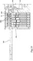
- Figures 1-6 illustrate a first embodiment of the cylinder lock 1.
- the cylinder lock 1 comprises a stator 2 and at least one cylindrical rotor 3.
- two rotors 3 are provided, arranged symmetrically so as to terminate at the respective inner and outer surfaces of a door or a window.
- the stator 2 has a cylindrical seat 4 which extends longitudinally between a front portion 2a and a rear portion 2b. "X" is used to indicate a longitudinal axis of the cylindrical seat 4.
- the stator 2 further has a plurality of radial holes 5 terminating in the cylindrical seat 4.
- the radial holes 5 have respective central axes arranged radially with respect to the longitudinal axis "X" and lying in the same plane containing the longitudinal axis "X".
- Preferably the radial holes 5 pass through the entire thickness of the stator 2 and, on the opposite side of the cylindrical seat 4, are closed by respective closure elements 6.
- the rotor 3 is housed in the cylindrical seat 4 such to be able to rotate around the longitudinal axis "X" in multiple angular positions.
- the surface that delimits the cylindrical seat 4 defines a sliding surface between the rotor 3 and the stator 2.
- the rotor 3 has a front opening 7 which provides access to a slit 8 that extends between the front opening 7 and a rear portion of the rotor and which therefore has a longitudinal extension which coincides with the longitudinal axis "X".
- the front opening 7 and the slit 8 are adapted to the insertion of the punched control key 100 i.e., with respect to the longitudinal axis "X", they have a transverse counter-shaped profile with respect to the transverse section of the punched control key 100.
- the rotor 3 has a plurality of radial holes 9 that terminate in the slit 8 and radially pass through the entire thickness of the rotor itself.
- the radial holes 9 of the rotor 3 have respective central axes arranged radially with respect to the longitudinal axis "X" and lying in the same plane containing the longitudinal axis "X".
- the cylinder lock 1 comprises a plurality of pistons, among which a plurality of locking pistons 10a are provided, each adapted to abut in an active punching 100a of the punched control key 100, and at least one anti-burglary piston 10b suited to abut in the active anti-burglary punching 100b of the punched control key 100.
- the anti-burglary piston 10b is the piston farthest from the front opening 7, therefore arranged in the rear portion of the rotor 3.
- Each piston 10a, 10b is housed in a radial hole 9 of the rotor 3 and is slidable along the central axis "Y".
- Each piston 10a, 10b comprises a control head 11 having an apex 12 protruding inside the slit 8 and a control surface 13a configured to come into contact with the punched control key 100 at an active punching 100a, 100b of the control key itself.
- Each piston is associated with a respective counter-piston 14, arranged in line with the piston itself along the central axis "Y" and in contact with it at the respective abutment ends, and an elastic element 15, arranged in line with the piston and the counter-piston along the central axis "Y” and in contact with the latter.
- Each counter-piston 14 is therefore interposed between an elastic element 15 and a piston 10a, 10b.
- Each elastic element 15 is housed in a radial hole 5 of the stator 2 and is thrustingly active on the respective counter-piston 14 to push the set constituted by the counter-piston and piston toward the slit 8. In the remainder of the present description, this movement will also be defined as lifting, independent of the fact that the pistons and counter-pistons are oriented vertically or in different angles.
- the set constituted by the piston and counter-piston is movable in opposition to the respective elastic element 15 as a result of the interaction between the control head 11 of the piston 10a, 10b and the punched control key 100.
- this movement will be also be defined as lowering, independent of the fact that the pistons and counter-pistons are oriented vertically or in different angles.
- the counter-pistons 14 are free to rise in their respective radial seats, pushed by the elastic elements 15, and to straddle between the rotor 3 and the stator 2, preventing the rotation of the rotor around the longitudinal axis "X".
- the punched control key 100 having the correct cuts is inserted into the slit 8, when the rotor 3 is in the angular alignment position.
- the abutment ends of the pistons and counter-pistons are aligned along the sliding surface between the rotor 3 and the stator 2.
- the punched control key 100 the rotor 3 is placed in rotation around the longitudinal axis "X", dragging the pistons with itself while the counter-pistons and the elastic elements remain housed in the stator 2.
- the relative control head 11 has a substantially conical or slightly truncated-conical shape, with the apex 12 lying on the central axis "Y".
- the control head 11 abuts against and comes into contact with a respective active punching 100a having a substantially conical or slightly truncated-conical shape, complementary shaped to the control head itself.
- the control surface 13a of the control head 11 is for example constituted by a top surface of the locking piston 10a, i.e. the apex 12.
- the relative control head 11 is shaped asymmetrically with respect to the central axis "Y", having the apex 12 lying on the opposite side of the front opening 7 with respect to the central axis "Y", i.e. at a rear portion of the anti-burglary piston 10b.
- the control head 11 of the anti-burglary piston 10b comprises a front surface 13b arranged toward the front opening 7, terminating at the apex 12 and intersecting the central axis "Y" of the radial hole 9 of the rotor 3 in which the anti-burglary piston 10b is housed.
- the front surface 13b is preferably inclined toward the apex 12 with respect to the central axis "Y".
- control surface 13a of the control head 11 of the anti-burglary piston 10b is inclined toward the apex 12 with respect to the central axis "Y" and is arranged on the part opposite the front opening 7 with respect to the central axis "Y" at the rear portion of the anti-burglary piston 10b.
- the control surface 13a abuts against and preferably only comes into contact with a rear portion of the active anti-burglary punching 100b.
- control head 11 of the anti-burglary piston 10b has a chisel shape with the front surface 13b and the control surface 13a having a planar shape and converging in the apex 12.
- the apex 12 thus has a linear shape and is preferably arranged in a direction perpendicular to the central axis "Y" and to the longitudinal extension of the slit 8, i.e. the longitudinal axis "X".
- the apex 12 having a linear shape has a length L1 which is smaller than the diameter "D" of the radial seat and of the body of the anti-burglary piston 10b and is preferably offset with respect to the central axis "Y" along a direction perpendicular to the longitudinal extension of the slit 8 ( figure 3 and figure 6 ).
- the anti-burglary piston 10b comprises an anti-rotation device 16 configured to keep the angular position of the anti-burglary piston 10b fixed around the central axis "Y".
- the anti-rotation device 16 comprises a tab 17 of the anti-burglary piston 10b that extends transversely with respect to the central axis "Y" to be inserted in a guide 18 of the rotor 3 parallel to the central axis "Y".
- the guide 18 is configured to allow the translation of the tab 17 along the central axis "Y” and to prevent rotation about the central axis "Y".
- Figure 1 illustrates the angular alignment position of the rotor 3 with the punched control key 100 inserted into the slit 8 and correctly interacting with the pistons 10a, 10b such to allow the rotation of the rotor 3 around the longitudinal axis "X".
- the active punchings 100a of the punched control key 100 are arranged along the longitudinal direction "A" such to be arranged symmetrically on the respective central axis "Y" of the cylinder lock and to circumferentially wind around the control head 11 at least to the depth that characterises them.
- the active anti-burglary punching 100b is also arranged along the longitudinal direction "A" such to be arranged symmetrically on the respective central axis "Y".
- the active anti-burglary punching 100b defines in its interior a volume greater than the volume occupied by the control head 11 of the anti-burglary piston 10b that is arranged in the rear portion of this volume.
- the control surface 13a comes into contact with the rear planar surface 108 of the active anti-burglary punching 100b and generates a gap 19 between the front surface 13b of the anti-burglary piston 10b and the front portion of the active anti-burglary punching 100b.
- the gap 19 is adapted to prevent burglary attempts using bumping keys, as will be described later.
- the active anti-burglary punching 100b already formed on the blank 200, and therefore also present on the punched control key 100 is configured and/or arranged to receive an anti-burglary piston 10b of the cylinder lock 1 resting on the rear planar surface 108, i.e. that which extends toward the free end 103, in a coupling condition between the punched control key 100 obtained from the blank 200 and the cylinder lock itself.
- the blocking of the rotation of the rotor 3 is performed in a manner similar to the locking pistons 10a and the anti-burglary piston 10b by extracting the punched control key 100.
- FIGS 4 and 5 illustrate a burglary attempt that exploits the method known as "key bumping", wherein a “bumping key” 300 is inserted into the slit 8 and hit from the outside to force the lowering of the pistons.
- the bumping key 300 is obtained starting from the blank 200, comprising the active anti-burglary punching 100b, wherein further punchings 300a are made having an identical depth equal to the maximum obtainable depth on the blank 200.
- all the locking pistons 10a abut against their maximum height at the further punching 300a.
- a gap 19 is however created between the front surface 13b of the anti-burglary piston 10b and the front portion of the active anti-burglary punching 100b.
- the percussion exerted on the bumping key 300 from the outside is not able to cancel the gap 19 and therefore cause the lowering of the anti-burglary piston 10b. Any further action on the active anti-burglary punching 100b would lead to an increase in the gap 19, thereby increasing the security of the cylinder lock.
- FIGS 7-11 illustrate a second embodiment of the cylinder lock 1.
- the elements which are shared with the first embodiment have been indicated with the same reference number.
- a particular shape of the anti-burglary piston 10b is not provided, as it has a control head 11, which is structurally and functionally similar to those of the locking pistons 10a.
- Its anti-burglary function is determined by its position, which leads it to abut in the active anti-burglary punching 100b of the punched control key 100.
- the blank 200 and the punched control key 100 comprise the active anti-burglary punching 100b, whose shape is preferably similar to that described previously.
- the active anti-burglary punching 100b is formed in a proximal position with respect to the free end 103 and the chute 110 that extends between the active anti-burglary punching 100b and the free end 103.
- the active anti-burglary punching 100b is arranged along the longitudinal direction "A" such to be positioned offset along the longitudinal axis "X", toward the front opening 7 of the cylinder lock 1, with respect to the apex 12 of the anti-burglary piston 10b and the central axis "Y", in a coupling condition between the control key 100 obtained from the blank 200 and the cylinder lock 1.
- the letter "S" is used to indicate the distance between the basic footprint 107 of the active anti-burglary punching 100b and the apex 12 of the anti-burglary piston 10b. This staggered arrangement can also be envisaged in the first embodiment.
- Figure 7 illustrates the angular alignment position of the rotor 3 with the punched control key 100 inserted into the slit 8 and correctly interacting with the pistons 10a, 10b such to allow the rotation of the rotor 3 around the longitudinal axis "X".
- the active punchings 100a of the punched control key 100 are arranged along the longitudinal direction “A” such to be arranged symmetrically on the respective central axis "Y” and to circumferentially wind around the control head 11 at least to the depth that characterises them.
- the active anti-burglary punching 100b is arranged along the longitudinal direction “A” such to be arranged offset along the longitudinal axis "X” toward the front portion of the rotor 3, with respect to the central axis "Y".
- the active anti-burglary punching 100b defines in its interior a volume greater than the volume occupied by the control head 11 of the anti-burglary piston 10b that abuts in the rear portion of this volume.
- the control head 11 comes into contact with the rear planar surface 108 of the active anti-burglary punching 100b and generates a gap 19 between the control head 11 of the anti-burglary piston 10b and the front portion of the active anti-burglary punching 100b.
- the active anti-burglary punching 100b of the blank 200 is configured and/or arranged to receive an anti-burglary piston 10b of the cylinder lock 1 resting on the rear planar surface 108, i.e. that which extends toward the free end 103, in a coupling condition between the punched control key 100 obtained from the blank 200 and the cylinder lock itself.
- the rotation of the rotor 3 is blocked in a similar manner to the locking pistons 10a and the anti-burglary piston 10b by extracting the anti-burglary control key.
- Figures 10 and 11 illustrate a burglary attempt that exploits the method known as "key bumping", wherein a “bumping key” 300 is inserted into the slit 8 and hit from the outside to force the lowering of the pistons.
- a "bumping key” 300 is inserted into the slit 8 and hit from the outside to force the lowering of the pistons.
- the percussion exerted on the bumping key 300 from the outside is not able to cancel the gap 19 and therefore cause the lowering of the anti-burglary piston 10b. Any further action on the active anti-burglary punching 100b would lead to an increase in the gap 19, thereby increasing the security of the cylinder lock.
- the cylinder lock 1 and/or the blank 200 for making a copy of the punched control key 100 define a locking system.
- the cylinder lock 1 comprises an anti-burglary piston 10b housed in a respective radial hole 9 of the rotor 3 and comprising a control head 11 configured to abut at the active anti-burglary punching 100b of the punched control key 100.
- the blank 200 already has the active anti-burglary punching 100b and the chute 110 that extends between the active anti-burglary punching 100b and the free end 103.
- the active anti-burglary punching 100b and/or the anti-burglary piston 10b are shaped and/or arranged in such a way that, in a coupling condition between the punched control key obtained from the blank 200 and the cylinder lock 1, the anti-burglary piston 10b abuts in the active anti-burglary punching 100b at a respective rear portion and that a front portion of the active anti-burglary punching 100b is arranged at a longitudinal distance "Z" from a front portion of the anti-burglary piston 10b in order to generate the gap 19.
- the longitudinal distance "Z" is greater than 1.7 mm, i.e. has a possible further longitudinal excursion obtainable on a bumping key 300, filing the abutment portion 111.
- the configuration and/or shape of the active anti-burglary punching 100b is uniquely associated to a given cylinder lock such to define a volume inside the active anti-burglary punching 100b which is greater than a volume occupied by the control head of the anti-burglary piston 10b.
Description
- The present invention relates to a locking system comprising a cylinder lock and a punched control key.
- Also disclosed but not forming part of the invention is a method for making a blank for duplicating a punched control key and a method for duplicating a punched control key.
- The term cylinder lock is intended as a type of lock in which a cylindrical drive rotor of the latch is rotatably housed in a stator and has a slit for receiving a punched control key. This key has flared punchings, which, following an elastic thrusting action, abut against control heads of pistons housed in the lock.
- The depth and position of the punchings constitute the cuts of the key that corresponds to the position of the pistons adapted to allow the rotation of the rotor. In fact, when the control key corresponding to the lock is inserted into the slit and the pistons abut in their respective punching, the opposite ends of the pistons align on the sliding surface between the rotor and stator, allowing the rotation of the rotor itself.
- One known method of opening this type of lock is called "key bumping", which consists in preparing a "bumping key" provided with punchings having the maximum depth obtainable in the thickness of the key itself. The bumping key can be inserted in the slit of the lock at a length greater than the control key. In general, the bumping key is made starting from a blank or untreated key, adapted to create a duplicate of the control key of the lock, providing thereon maximum-depth punchings and filing the typical stop abutments of the control key.
- By inserting the bumping key in the slit, all the pistons arrange at their maximum height. By hitting the key to push it further into the slit, the pistons are subjected to an impact in a radial direction, making the rotation of the rotor possible.
-
DE4036158 discloses a key blank provided with a pre-cut punching and a chute.US6105404 discloses a system in which a plurality of different keys that operate different locks can be used to operate a common lock.EP2281985 discloses a cylinder lock in which the distances of the contact surfaces of the pins are different. This arrangement is achieved changing the position of at least one pin with respect to the others or providing at least a pin with a diameter larger than the others.EP2108767 discloses a cylinder lock with at least one pusher which defines a safety position for at least one first pin in which the first pin is spaced from the wall even when no key is inserted in the slot.EP2108767 discloses a cylinder lock comprising an asymmetrically shaped head. - In this context, the technical task underlying the present invention is to propose a locking system, in particular a cylinder lock and a punched control key, able to resist such an opening method.
- The stated technical task and the aims specified are substantially achieved by a locking system comprising a cylinder lock and a punched control key and by a blank for making a duplicate of the punched control key, each comprising the technical features described in one or more of the accompanying claims.
- In particular, the present invention relates to a locking system comprising a cylinder lock and a punched control key according to
claim 1. - The present invention may additionally comprise one or more of the characteristics set forth in the dependent claims, incorporated here for reference, each corresponding to a possible embodiment.
- Additional features and advantages of the present invention will become more apparent from the indicative, and thus non-limiting description that follows. This description is provided herein below with reference to the attached drawings, which are provided solely for purpose of providing approximate and thus non-limiting examples, of which:
-
figure 1 is a schematic, longitudinal section view of a first embodiment of a cylinder lock associated with a respective punched control key; -
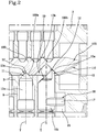
figure 2 is an enlarged view of detail II infigure 1 ; -
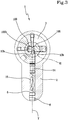
figure 3 is a sectional view according to track III-III infigure 1 ; -
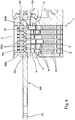
figure 4 is a schematic, longitudinal section view of the cylinder lock offigure 1 associated with a bumping key; -
figure 5 is an enlarged view of detail V infigure 4 ; -
figure 6 is an enlarged view of detail VI infigure 3 ; -
figure 7 is a schematic, longitudinal section view of a second embodiment of a cylinder lock associated with a respective punched control key; -
figure 8 is an enlarged view of detail VIII infigure 7 ; -
figure 9 is a sectional view according to track IX-IX infigure 7 ; -
figure 10 is a schematic, longitudinal section view of the cylinder lock offigure 7 associated with a bumping key; -
figure 11 is an enlarged view of detail XI infigure 10 ; -
figure 12 is a schematic perspective view of a blank for making a duplicate of a punched control key adapted to be used in a cylinder lock; -
figure 13 is a schematic plan view of a punched control key adapted to be used in a cylinder lock. - With reference to the accompanying figures, the
number 1 comprehensively denotes a cylinder lock, thenumber 100 denotes a punched control key adapted to control the unlocking and locking of thecylinder lock 1 and thenumber 200 denotes a blank or untreated key for making a copy of the punchedcontrol key 100. - Referring for example to
figures 1 ,7 and13 , the punchedcontrol key 100 comprises agrip 101 and a plate-like body 102 that mainly extends along a longitudinal direction "A" from thegrip 101 toward afree end 103. In other words the punchedcontrol key 100, in particular the plate-like body 102, has a longitudinal dimension greater than the transverse dimensions, with reference to the longitudinal direction "A". In turn, a transverse direction of the plate-like body 102 is greater than the other one so as to define twomajor side surfaces 102a and twominor side surfaces 102b. - At least one
major side surface 102a of the plate-like body 102 has alongitudinal trail 104, a firstlongitudinal track 105 on whichactive punchings longitudinal track 106 on whichpassive punchings 100c can be made. Preferably, the punchedcontrol key 100 is reversible, i.e. the twomajor side surfaces 102a of the plate-like body 102 are identical as a result of a 180° rotation of the punched control key around the longitudinal direction "A". - Further passive punchings 100d can possibly be provided on a
minor side surface 102b of the plate-like body 102. - The active punchings have a flared shape, for example conical, with varying depths in relation to the cuts of the punched
control key 100. Among the active punchings, the punchedcontrol key 100 comprises an activeanti-burglary punching 100b formed in a proximal position with respect to thefree end 103. - Preferably, the active
anti-burglary punching 100b has abasic footprint 107 having an elongated shape in a direction perpendicular to the longitudinal direction "A" of the plate-like body 102. Even more preferably, the activeanti-burglary punching 100b has twoplanar surfaces 108 that extend from thebasic footprint 107 connected by substantially truncated-conical side surfaces 109. The overall activeanti-burglary punching 100b has a flared shape, both at theplanar surfaces 108 and at theside surfaces 109. Aplanar surface 108 extends toward thefree end 103, forming a rearplanar surface 108. The otherplanar surface 108 extends toward thegrip 101, forming a frontplanar surface 108. - The active
anti-burglary punching 100b has a width at the base equal to 0.5 mm, length equal to 1.7 mm and depth equal to 1.5 mm. - In general, the term "front" is used to indicate a portion and/or an element arranged and/or facing toward the
grip 101, with reference to the punchedcontrol key 100, or toward an insertion area of the punchedcontrol key 100 in thecylinder lock 1, with reference to the lock itself. Similarly, the term "rear" is used to indicate a portion and/or an element arranged and/or facing toward thefree end 103, with reference to the punchedcontrol key 100 or toward the part opposite the insertion area of the punchedcontrol key 100 in thecylinder lock 1, with reference to the lock itself. - The major side surface of the plate-
like body 102 also has achute 110 that extends between the activeanti-burglary punching 100b and thefree end 103. - Along the longitudinal direction "A" of the punched
control key 100, anabutment portion 111 is provided, preferably twoabutment portions 111, which in the use of the punchedcontrol key 100 abuts against a corresponding abutment portion of thecylinder lock 1 such that the punchedcontrol key 100 has a predefined longitudinal dimension of insertion "H" and the active punchings are arranged in respective predefined longitudinal positions within the cylinder lock. By way of example the basic footprint of the activeanti-burglary punching 100b is arranged at a position longitudinally placed at a distance H1 equal to 18.5 mm from the abutment portion in the case that will be described in reference tofigure 1 and equal to 17.9 mm in the case that will be described in reference tofigure 7 . - To make a duplicate of the punched
control key 100, use of the blank 200 or an untreated key is envisaged, for whichfigure 12 constitutes a possible non-limiting exemplary embodiment. The blank 200 has certain features in common with the punchedcontrol key 100 that have been indicated infigure 12 with the same reference number. In fact, the blank 200 comprises thegrip 101 and the plate-like body 102 with at least onemajor side surface 102a provided with thelongitudinal trail 104. The firstlongitudinal track 105 is adapted to receive theactive punchings 100a of thecontrol key 100 and the secondlongitudinal track 106 is adapted to receive thepassive punchings 100c of thecontrol key 100. - The first
longitudinal track 105 already has the activeanti-burglary punching 100b formed in a proximal position with respect to thefree end 103, and thechute 110 that extends between the activeanti-burglary punching 100b and thefree end 103. - In other words, the creation of the active
anti-burglary punching 100b is envisaged directly on the same blank, as well as duplicating a punchedcontrol key 100 starting from this blank, by completing theactive punchings 100a on the firstlongitudinal track 105. -
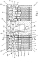
Figures 1-6 illustrate a first embodiment of thecylinder lock 1. - The
cylinder lock 1 comprises astator 2 and at least onecylindrical rotor 3. In the illustrated examples, tworotors 3 are provided, arranged symmetrically so as to terminate at the respective inner and outer surfaces of a door or a window. - The
stator 2 has acylindrical seat 4 which extends longitudinally between afront portion 2a and arear portion 2b. "X" is used to indicate a longitudinal axis of thecylindrical seat 4. - The
stator 2 further has a plurality ofradial holes 5 terminating in thecylindrical seat 4. The radial holes 5 have respective central axes arranged radially with respect to the longitudinal axis "X" and lying in the same plane containing the longitudinal axis "X". Preferably theradial holes 5 pass through the entire thickness of thestator 2 and, on the opposite side of thecylindrical seat 4, are closed byrespective closure elements 6. Therotor 3 is housed in thecylindrical seat 4 such to be able to rotate around the longitudinal axis "X" in multiple angular positions. The surface that delimits thecylindrical seat 4 defines a sliding surface between therotor 3 and thestator 2. - The
rotor 3 has afront opening 7 which provides access to aslit 8 that extends between thefront opening 7 and a rear portion of the rotor and which therefore has a longitudinal extension which coincides with the longitudinal axis "X". Thefront opening 7 and theslit 8 are adapted to the insertion of the punchedcontrol key 100 i.e., with respect to the longitudinal axis "X", they have a transverse counter-shaped profile with respect to the transverse section of the punchedcontrol key 100. - The
rotor 3 has a plurality ofradial holes 9 that terminate in theslit 8 and radially pass through the entire thickness of the rotor itself. The radial holes 9 of therotor 3 have respective central axes arranged radially with respect to the longitudinal axis "X" and lying in the same plane containing the longitudinal axis "X". - In the angular position of the
rotor 3 shown infigure 1 , corresponding to an angular alignment position, theradial holes 5 of thestator 2 and theradial holes 9 of therotor 3 are aligned to form a plurality of radial recesses that extend along the respective central axes comprehensively indicated with the letter "Y". - The
cylinder lock 1 comprises a plurality of pistons, among which a plurality of lockingpistons 10a are provided, each adapted to abut in anactive punching 100a of the punchedcontrol key 100, and at least oneanti-burglary piston 10b suited to abut in the active anti-burglary punching 100b of the punchedcontrol key 100. Preferably, theanti-burglary piston 10b is the piston farthest from thefront opening 7, therefore arranged in the rear portion of therotor 3. - Each
piston radial hole 9 of therotor 3 and is slidable along the central axis "Y". - Each
piston control head 11 having an apex 12 protruding inside theslit 8 and acontrol surface 13a configured to come into contact with the punchedcontrol key 100 at anactive punching - Each piston is associated with a
respective counter-piston 14, arranged in line with the piston itself along the central axis "Y" and in contact with it at the respective abutment ends, and anelastic element 15, arranged in line with the piston and the counter-piston along the central axis "Y" and in contact with the latter. Eachcounter-piston 14 is therefore interposed between anelastic element 15 and apiston - Each
elastic element 15 is housed in aradial hole 5 of thestator 2 and is thrustingly active on therespective counter-piston 14 to push the set constituted by the counter-piston and piston toward theslit 8. In the remainder of the present description, this movement will also be defined as lifting, independent of the fact that the pistons and counter-pistons are oriented vertically or in different angles. - In addition, the set constituted by the piston and counter-piston is movable in opposition to the respective
elastic element 15 as a result of the interaction between thecontrol head 11 of thepiston control key 100. In the remainder of the present description, this movement will be also be defined as lowering, independent of the fact that the pistons and counter-pistons are oriented vertically or in different angles. - In use, when the
rotor 3 is in the angular alignment position and the punchedcontrol key 100 is outside theslit 8, the counter-pistons 14 are free to rise in their respective radial seats, pushed by theelastic elements 15, and to straddle between therotor 3 and thestator 2, preventing the rotation of the rotor around the longitudinal axis "X". - To free the rotation of the
rotor 3, the punchedcontrol key 100 having the correct cuts is inserted into theslit 8, when therotor 3 is in the angular alignment position. Finding abutment in the respective active punchings 100a, 100b, thepistons elastic elements 15. The abutment ends of the pistons and counter-pistons are aligned along the sliding surface between therotor 3 and thestator 2. Using the punchedcontrol key 100, therotor 3 is placed in rotation around the longitudinal axis "X", dragging the pistons with itself while the counter-pistons and the elastic elements remain housed in thestator 2. - In the case of locking
pistons 10a, therelative control head 11 has a substantially conical or slightly truncated-conical shape, with the apex 12 lying on the central axis "Y". To free the rotation of therotor 3, thecontrol head 11 abuts against and comes into contact with a respectiveactive punching 100a having a substantially conical or slightly truncated-conical shape, complementary shaped to the control head itself. Thecontrol surface 13a of thecontrol head 11 is for example constituted by a top surface of thelocking piston 10a, i.e. the apex 12. - In the case of an
anti-burglary piston 10b, therelative control head 11 is shaped asymmetrically with respect to the central axis "Y", having the apex 12 lying on the opposite side of thefront opening 7 with respect to the central axis "Y", i.e. at a rear portion of theanti-burglary piston 10b. Preferably thecontrol head 11 of theanti-burglary piston 10b comprises afront surface 13b arranged toward thefront opening 7, terminating at the apex 12 and intersecting the central axis "Y" of theradial hole 9 of therotor 3 in which theanti-burglary piston 10b is housed. Thefront surface 13b is preferably inclined toward the apex 12 with respect to the central axis "Y". - Preferably, the
control surface 13a of thecontrol head 11 of theanti-burglary piston 10b is inclined toward the apex 12 with respect to the central axis "Y" and is arranged on the part opposite thefront opening 7 with respect to the central axis "Y" at the rear portion of theanti-burglary piston 10b. To free the rotation of therotor 3, thecontrol surface 13a abuts against and preferably only comes into contact with a rear portion of the activeanti-burglary punching 100b. - In one possible embodiment for which the accompanying drawings constitute a non-limiting example, the
control head 11 of theanti-burglary piston 10b has a chisel shape with thefront surface 13b and thecontrol surface 13a having a planar shape and converging in the apex 12. The apex 12 thus has a linear shape and is preferably arranged in a direction perpendicular to the central axis "Y" and to the longitudinal extension of theslit 8, i.e. the longitudinal axis "X". - In one possible embodiment for which the accompanying drawings constitute a non-limiting example, the apex 12 having a linear shape has a length L1 which is smaller than the diameter "D" of the radial seat and of the body of the
anti-burglary piston 10b and is preferably offset with respect to the central axis "Y" along a direction perpendicular to the longitudinal extension of the slit 8 (figure 3 andfigure 6 ). - In one possible embodiment for which the accompanying drawings constitute a non-limiting example, the
anti-burglary piston 10b comprises ananti-rotation device 16 configured to keep the angular position of theanti-burglary piston 10b fixed around the central axis "Y". Preferably, theanti-rotation device 16 comprises atab 17 of theanti-burglary piston 10b that extends transversely with respect to the central axis "Y" to be inserted in aguide 18 of therotor 3 parallel to the central axis "Y". Theguide 18 is configured to allow the translation of thetab 17 along the central axis "Y" and to prevent rotation about the central axis "Y". - In use, to free the rotation of the
rotor 3, the lockingpistons 10a abut in the respective active punchings 100a of the punchedcontrol key 100 while theanti-burglary piston 10b abuts in the activeanti-burglary punching 100b in mutual contact only at the respective rear portions.Figure 1 illustrates the angular alignment position of therotor 3 with the punchedcontrol key 100 inserted into theslit 8 and correctly interacting with thepistons rotor 3 around the longitudinal axis "X". It can be noted that the active punchings 100a of the punchedcontrol key 100 are arranged along the longitudinal direction "A" such to be arranged symmetrically on the respective central axis "Y" of the cylinder lock and to circumferentially wind around thecontrol head 11 at least to the depth that characterises them. - Preferably, the active
anti-burglary punching 100b is also arranged along the longitudinal direction "A" such to be arranged symmetrically on the respective central axis "Y". The activeanti-burglary punching 100b defines in its interior a volume greater than the volume occupied by thecontrol head 11 of theanti-burglary piston 10b that is arranged in the rear portion of this volume. In other words, in the interaction between thecontrol head 11 of theanti-burglary piston 10b and activeanti-burglary punching 100b, thecontrol surface 13a comes into contact with the rearplanar surface 108 of the activeanti-burglary punching 100b and generates agap 19 between thefront surface 13b of theanti-burglary piston 10b and the front portion of the activeanti-burglary punching 100b. Thegap 19 is adapted to prevent burglary attempts using bumping keys, as will be described later. In other words, the activeanti-burglary punching 100b already formed on the blank 200, and therefore also present on the punchedcontrol key 100, is configured and/or arranged to receive ananti-burglary piston 10b of thecylinder lock 1 resting on the rearplanar surface 108, i.e. that which extends toward thefree end 103, in a coupling condition between the punchedcontrol key 100 obtained from the blank 200 and the cylinder lock itself. - The blocking of the rotation of the
rotor 3 is performed in a manner similar to thelocking pistons 10a and theanti-burglary piston 10b by extracting the punchedcontrol key 100. -
Figures 4 and5 illustrate a burglary attempt that exploits the method known as "key bumping", wherein a "bumping key" 300 is inserted into theslit 8 and hit from the outside to force the lowering of the pistons. - The bumping
key 300 is obtained starting from the blank 200, comprising the activeanti-burglary punching 100b, whereinfurther punchings 300a are made having an identical depth equal to the maximum obtainable depth on the blank 200. When the bumpingkey 300 is inserted into theslit 8 all thelocking pistons 10a abut against their maximum height at thefurther punching 300a. In the interaction between thecontrol head 11 of theanti-burglary piston 10b and the active anti-burglary punching 100b of the bumpingkey 300, agap 19 is however created between thefront surface 13b of theanti-burglary piston 10b and the front portion of the activeanti-burglary punching 100b. The percussion exerted on the bumping key 300 from the outside is not able to cancel thegap 19 and therefore cause the lowering of theanti-burglary piston 10b. Any further action on the activeanti-burglary punching 100b would lead to an increase in thegap 19, thereby increasing the security of the cylinder lock. -
Figures 7-11 illustrate a second embodiment of thecylinder lock 1. The elements which are shared with the first embodiment have been indicated with the same reference number. In this case, a particular shape of theanti-burglary piston 10b is not provided, as it has acontrol head 11, which is structurally and functionally similar to those of the lockingpistons 10a. Its anti-burglary function is determined by its position, which leads it to abut in the active anti-burglary punching 100b of the punchedcontrol key 100. - The blank 200 and the punched
control key 100 comprise the activeanti-burglary punching 100b, whose shape is preferably similar to that described previously. - The active
anti-burglary punching 100b is formed in a proximal position with respect to thefree end 103 and thechute 110 that extends between the activeanti-burglary punching 100b and thefree end 103. The activeanti-burglary punching 100b is arranged along the longitudinal direction "A" such to be positioned offset along the longitudinal axis "X", toward thefront opening 7 of thecylinder lock 1, with respect to the apex 12 of theanti-burglary piston 10b and the central axis "Y", in a coupling condition between thecontrol key 100 obtained from the blank 200 and thecylinder lock 1. Infigure 8 the letter "S" is used to indicate the distance between thebasic footprint 107 of the activeanti-burglary punching 100b and the apex 12 of theanti-burglary piston 10b. This staggered arrangement can also be envisaged in the first embodiment. - In use, to free the rotation of the
rotor 3, the lockingpistons 10a abut in the respective active punchings 100a of the punched control key while theanti-burglary piston 10b abuts in the activeanti-burglary punching 100b in mutual contact at the respective rear portions.Figure 7 illustrates the angular alignment position of therotor 3 with the punchedcontrol key 100 inserted into theslit 8 and correctly interacting with thepistons rotor 3 around the longitudinal axis "X". It can be noted that the active punchings 100a of the punchedcontrol key 100 are arranged along the longitudinal direction "A" such to be arranged symmetrically on the respective central axis "Y" and to circumferentially wind around thecontrol head 11 at least to the depth that characterises them. The activeanti-burglary punching 100b is arranged along the longitudinal direction "A" such to be arranged offset along the longitudinal axis "X" toward the front portion of therotor 3, with respect to the central axis "Y". - Also in this case, the active
anti-burglary punching 100b defines in its interior a volume greater than the volume occupied by thecontrol head 11 of theanti-burglary piston 10b that abuts in the rear portion of this volume. In other words, in the interaction between thecontrol head 11 of theanti-burglary piston 10b and activeanti-burglary punching 100b, thecontrol head 11 comes into contact with the rearplanar surface 108 of the activeanti-burglary punching 100b and generates agap 19 between thecontrol head 11 of theanti-burglary piston 10b and the front portion of the activeanti-burglary punching 100b. - In other words, the active anti-burglary punching 100b of the blank 200 is configured and/or arranged to receive an
anti-burglary piston 10b of thecylinder lock 1 resting on the rearplanar surface 108, i.e. that which extends toward thefree end 103, in a coupling condition between the punchedcontrol key 100 obtained from the blank 200 and the cylinder lock itself. - The rotation of the
rotor 3 is blocked in a similar manner to thelocking pistons 10a and theanti-burglary piston 10b by extracting the anti-burglary control key. -
Figures 10 and11 illustrate a burglary attempt that exploits the method known as "key bumping", wherein a "bumping key" 300 is inserted into theslit 8 and hit from the outside to force the lowering of the pistons. As previously described, the percussion exerted on the bumping key 300 from the outside is not able to cancel thegap 19 and therefore cause the lowering of theanti-burglary piston 10b. Any further action on the activeanti-burglary punching 100b would lead to an increase in thegap 19, thereby increasing the security of the cylinder lock. - In general terms, the
cylinder lock 1 and/or the blank 200 for making a copy of the punchedcontrol key 100 define a locking system. - The
cylinder lock 1 comprises ananti-burglary piston 10b housed in a respectiveradial hole 9 of therotor 3 and comprising acontrol head 11 configured to abut at the active anti-burglary punching 100b of the punchedcontrol key 100. - The blank 200 already has the active
anti-burglary punching 100b and thechute 110 that extends between the activeanti-burglary punching 100b and thefree end 103. - The active
anti-burglary punching 100b and/or theanti-burglary piston 10b are shaped and/or arranged in such a way that, in a coupling condition between the punched control key obtained from the blank 200 and thecylinder lock 1, theanti-burglary piston 10b abuts in the activeanti-burglary punching 100b at a respective rear portion and that a front portion of the activeanti-burglary punching 100b is arranged at a longitudinal distance "Z" from a front portion of theanti-burglary piston 10b in order to generate thegap 19. - The longitudinal distance "Z" is greater than 1.7 mm, i.e. has a possible further longitudinal excursion obtainable on a bumping
key 300, filing theabutment portion 111. - The configuration and/or shape of the active
anti-burglary punching 100b is uniquely associated to a given cylinder lock such to define a volume inside the activeanti-burglary punching 100b which is greater than a volume occupied by the control head of theanti-burglary piston 10b.
Claims (14)
- A locking system comprising a cylinder lock (1) and a punched control key (100), wherein the cylinder lock (1) comprises:- a stator (2) having a cylindrical seat (4), which extends along a longitudinal axis (X) between a front portion (2a) and a rear portion (2b), and a plurality of radial holes (5) terminating in said cylindrical seat (4),- at least one rotatating cylindrical rotor (3) housed in said cylindrical seat (4) and having a front opening (7) which grants access to a slit (8) having a longitudinal extension coinciding with the longitudinal axis (X) and adapted to receive said punched control key (100), wherein said rotor (3) has a plurality of radial holes (9) that terminate in said slit (8) and that, in an angular alignment position of said rotor (3), are aligned with the radial holes (5) of the stator (2) to form a plurality of radial seats that extend along respective central axes (Y),- a plurality of pistons (10a, 10b), each piston being housed in a radial hole (9) of the rotor (3), slidable along said central axis (Y) and comprising a control head (11) having an apex (12) projecting inside the slit (8) and configured to abut at an active punching (100a, 100b) of the punched control key (100),- a plurality of elastic elements (15), each elastic element being housed in a radial hole (5) of the stator (2),- a plurality of counter-pistons (14), each counter-piston being interposed between an elastic element (15) and a piston (10a, 10b),wherein each elastic element (15) is thrustingly active on the respective counter-piston (14) to push said counter-piston and said piston toward said slit (8) and wherein said piston and said counter-piston are movable in opposition to the respective elastic element (15) as a result of the interaction between the control head (11) and the punched control key (100),characterised in that said plurality of pistons comprises an anti-burglary piston (10b),wherein the punched control key (100) comprises an active anti-burglary punching (100b) formed in a proximal position with respect to a free end (103) and a chute (110) that extends between said active anti-burglary punching (100b) and said free end (103),and wherein in a coupling condition between the punched control key (100) obtained from a blank (200) and the cylinder lock (1), the anti-burglary piston (10b) abuts in the active anti-burglary punching (100b) at a respective rear portion and that a front portion of the active anti-burglary punching (100b) is arranged at a longitudinal distance (Z) from a front portion of the anti-burglary piston (10b) in order to generate the gap (19) adapted to prevent burglary attempts using bumping keys.
- The locking system according to claim 1, wherein said anti-burglary piston (10b) comprises said control head (11) shaped asymmetrically with respect to said central axis (Y), with said apex (12) arranged on the opposite side of the front opening (7) with respect to said central axis (Y), at a rear portion of said anti-burglary piston (10b)
- The locking system according to claim 2, wherein said control head (11) of said anti-burglary piston (10b) comprises a front surface (13b) arranged toward said front opening (7), terminating at said apex (12) and intersecting said central axis (Y).
- The locking system according to claim 3, wherein said front surface (13b) is inclined toward said apex (12) with respect to said central axis (Y).
- The locking system according to one or more of the preceding claims 2-4, wherein said control head (11) of said anti-burglary piston (10b) comprises a control surface (13a) inclined toward said apex (12) with respect to said central axis (Y) and arranged on the opposite side of said front opening (7) with respect to said central axis (Y) at the rear portion of the anti-burglary piston (10b).
- The locking system according to one or more of the preceding claims 2-5, wherein said control head (11) of said anti-burglary piston (10b) has a chisel shape with a front surface (13b), and a control surface (13a) having a planar shape converging in said apex (12) having a linear shape.
- The locking system according to claim 6, wherein said apex (12) having a linear shape is arranged in a direction perpendicular to said central axis (Y) and to said longitudinal axis (X).
- The locking system according to claim 7, wherein said apex (12) having a linear shape has a length (L1) smaller than the diameter (D) of said radial hole (9) of the rotor (3) and is preferably offset with respect to said central axis (Y) along a direction perpendicular to said longitudinal axis (X).
- The locking system according to one or more of the preceding claims, wherein said anti-burglary piston (10b) is the piston which is most distant from the front opening (7), arranged in the rear portion of the rotor (3).
- The locking system according to one or more of the preceding claims 2-8, wherein said anti-burglary piston (10b) comprises an anti-rotation device (16) configured to maintain the angular position of the anti-burglary piston constant around the central axis (Y).
- The locking system according to one or more of the preceding claims, wherein said active anti-burglary punching (100b) and/or said control head (11) of the anti-burglary piston (10b) are shaped and/or arranged in such a way that, in the coupling condition, said control head (11) abuts in said active anti-burglary punching (100b) and is arranged in the rear portion of the internal volume of the active anti-burglary punching (100b), leaving a gap (19) between the control head (11) of the anti-burglary piston (10b) and a front portion of the active anti-burglary punching (100b), said gap (19) being adapted to prevent burglary attempts using bumping keys.
- The locking system according to one or more of the preceding claims, wherein the active anti-burglary punching (100b) defines in its interior a volume greater than the volume occupied by the control head (11) of the anti-burglary piston (10b) that, in the coupling condition, is arranged in the rear portion of this volume.
- The locking system according to claim 11 or 12, wherein the plurality of pistons of the cylinder lock (1) comprises a plurality of locking pistons (10a) each adapted to abut in an active punching (100a) of the punched control key (100) and wherein the anti-burglary piston (10b) has a control head (11) which is structurally and functionally similar to those of the locking pistons (10a).
- The locking system according to one or more of claim 11-13, wherein the active anti-burglary punching (100b) is arranged along a longitudinal direction (A) of the punched control key (100) such to be positioned offset along the longitudinal axis (X), toward the front opening (7) of the cylinder lock (1), with respect to the apex (12) of the anti-burglary piston (10b), in the coupling condition, the basic footprint (107) of the active anti-burglary punching (100b) being disposed at a distance (S) from the apex (12) of the anti-burglary piston (10b).
Priority Applications (1)
| Application Number | Priority Date | Filing Date | Title |
|---|---|---|---|
| EP18196591.4A EP3628800B1 (en) | 2018-09-25 | 2018-09-25 | Locking system comprising cylinder lock and a punched control key |
Applications Claiming Priority (1)
| Application Number | Priority Date | Filing Date | Title |
|---|---|---|---|
| EP18196591.4A EP3628800B1 (en) | 2018-09-25 | 2018-09-25 | Locking system comprising cylinder lock and a punched control key |
Publications (2)
| Publication Number | Publication Date |
|---|---|
| EP3628800A1 EP3628800A1 (en) | 2020-04-01 |
| EP3628800B1 true EP3628800B1 (en) | 2021-12-01 |
Family
ID=63794296
Family Applications (1)
| Application Number | Title | Priority Date | Filing Date |
|---|---|---|---|
| EP18196591.4A Active EP3628800B1 (en) | 2018-09-25 | 2018-09-25 | Locking system comprising cylinder lock and a punched control key |
Country Status (1)
| Country | Link |
|---|---|
| EP (1) | EP3628800B1 (en) |
Family Cites Families (5)
| Publication number | Priority date | Publication date | Assignee | Title |
|---|---|---|---|---|
| CH679507A5 (en) * | 1989-12-15 | 1992-02-28 | Bauer Kaba Ag | |
| DE4313066A1 (en) * | 1993-04-21 | 1994-10-27 | Danijel Golub | Keys and tumblers for multi-locking systems |
| US6105404A (en) * | 1998-06-30 | 2000-08-22 | Medeco Security Locks, Inc. | Squiggle keys and cylinder locks for squiggle keys |
| ITPD20080110A1 (en) * | 2008-04-09 | 2009-10-10 | Alban Giacomo Spa | "LOCKED CYLINDER LOCK STRUCTURE" |
| AT508869B1 (en) * | 2009-08-06 | 2013-07-15 | Evva Sicherheitstechnologie | KEY AND CYLINDER LOCK |
-
2018
- 2018-09-25 EP EP18196591.4A patent/EP3628800B1/en active Active
Also Published As
| Publication number | Publication date |
|---|---|
| EP3628800A1 (en) | 2020-04-01 |
Similar Documents
| Publication | Publication Date | Title |
|---|---|---|
| US4377940A (en) | Impression-resistant lock | |
| US4393673A (en) | Cylinder lock | |
| US3499302A (en) | Cylinder lock | |
| EP2173954B1 (en) | Hierarchical cylinder lock system | |
| US6910356B2 (en) | Anti-pick mogul cylinder | |
| USRE30198E (en) | Cylinder lock | |
| AU2011289709B2 (en) | Tool-less rekeyable lock cylinder | |
| EP2899337B1 (en) | Lock system | |
| CA1230986A (en) | Magnetic lock insert for lock mechanisms | |
| EP3628800B1 (en) | Locking system comprising cylinder lock and a punched control key | |
| WO2014124342A1 (en) | Lockdown cylinder locks | |
| EP1247926A2 (en) | Assembly of revolving cylinder lock and key | |
| US6755062B2 (en) | Anti-pick mogul deadlock | |
| PL181906B1 (en) | Locking cylinder and method of making same | |
| EP3144453A1 (en) | Key and key cylinder | |
| WO2016179631A1 (en) | Lock and key therefor | |
| US7793528B2 (en) | Key-operated mechanical lock | |
| EP1366256B1 (en) | Rotating pin tumbler side bar lock with side bar control | |
| EP3097243B1 (en) | Cylinder lock and key in combination with the cylinder lock | |
| GB2506580A (en) | Pin tumbler lock resistant to picking | |
| US20120079860A1 (en) | Improvements to key-operated pin tumbler locks | |
| AU2013204413A1 (en) | Lock system | |
| EP1746228A2 (en) | Cylinder lock with protection against manipulation by impacts | |
| GB2186321A (en) | Magnetic lock insert for lock mechanisms |
Legal Events
| Date | Code | Title | Description |
|---|---|---|---|
| PUAI | Public reference made under article 153(3) epc to a published international application that has entered the european phase |
Free format text: ORIGINAL CODE: 0009012 |
|
| STAA | Information on the status of an ep patent application or granted ep patent |
Free format text: STATUS: THE APPLICATION HAS BEEN PUBLISHED |
|
| AK | Designated contracting states |
Kind code of ref document: A1 Designated state(s): AL AT BE BG CH CY CZ DE DK EE ES FI FR GB GR HR HU IE IS IT LI LT LU LV MC MK MT NL NO PL PT RO RS SE SI SK SM TR |
|
| AX | Request for extension of the european patent |
Extension state: BA ME |
|
| STAA | Information on the status of an ep patent application or granted ep patent |
Free format text: STATUS: REQUEST FOR EXAMINATION WAS MADE |
|
| 17P | Request for examination filed |
Effective date: 20200929 |
|
| RBV | Designated contracting states (corrected) |
Designated state(s): AL AT BE BG CH CY CZ DE DK EE ES FI FR GB GR HR HU IE IS IT LI LT LU LV MC MK MT NL NO PL PT RO RS SE SI SK SM TR |
|
| STAA | Information on the status of an ep patent application or granted ep patent |
Free format text: STATUS: EXAMINATION IS IN PROGRESS |
|
| 17Q | First examination report despatched |
Effective date: 20210310 |
|
| GRAP | Despatch of communication of intention to grant a patent |
Free format text: ORIGINAL CODE: EPIDOSNIGR1 |
|
| STAA | Information on the status of an ep patent application or granted ep patent |
Free format text: STATUS: GRANT OF PATENT IS INTENDED |
|
| INTG | Intention to grant announced |
Effective date: 20210913 |
|
| RIN1 | Information on inventor provided before grant (corrected) |
Inventor name: ALBAN, GIACOMO MARIO |
|
| GRAS | Grant fee paid |
Free format text: ORIGINAL CODE: EPIDOSNIGR3 |
|
| GRAA | (expected) grant |
Free format text: ORIGINAL CODE: 0009210 |
|
| STAA | Information on the status of an ep patent application or granted ep patent |
Free format text: STATUS: THE PATENT HAS BEEN GRANTED |
|
| AK | Designated contracting states |
Kind code of ref document: B1 Designated state(s): AL AT BE BG CH CY CZ DE DK EE ES FI FR GB GR HR HU IE IS IT LI LT LU LV MC MK MT NL NO PL PT RO RS SE SI SK SM TR |
|
| REG | Reference to a national code |
Ref country code: GB Ref legal event code: FG4D |
|
| REG | Reference to a national code |
Ref country code: AT Ref legal event code: REF Ref document number: 1451914 Country of ref document: AT Kind code of ref document: T Effective date: 20211215 Ref country code: CH Ref legal event code: EP |
|
| REG | Reference to a national code |
Ref country code: IE Ref legal event code: FG4D |
|
| REG | Reference to a national code |
Ref country code: DE Ref legal event code: R096 Ref document number: 602018027394 Country of ref document: DE |
|
| REG | Reference to a national code |
Ref country code: LT Ref legal event code: MG9D |
|
| REG | Reference to a national code |
Ref country code: NL Ref legal event code: MP Effective date: 20211201 |
|
| REG | Reference to a national code |
Ref country code: AT Ref legal event code: MK05 Ref document number: 1451914 Country of ref document: AT Kind code of ref document: T Effective date: 20211201 |
|
| PG25 | Lapsed in a contracting state [announced via postgrant information from national office to epo] |
Ref country code: RS Free format text: LAPSE BECAUSE OF FAILURE TO SUBMIT A TRANSLATION OF THE DESCRIPTION OR TO PAY THE FEE WITHIN THE PRESCRIBED TIME-LIMIT Effective date: 20211201 Ref country code: LT Free format text: LAPSE BECAUSE OF FAILURE TO SUBMIT A TRANSLATION OF THE DESCRIPTION OR TO PAY THE FEE WITHIN THE PRESCRIBED TIME-LIMIT Effective date: 20211201 Ref country code: FI Free format text: LAPSE BECAUSE OF FAILURE TO SUBMIT A TRANSLATION OF THE DESCRIPTION OR TO PAY THE FEE WITHIN THE PRESCRIBED TIME-LIMIT Effective date: 20211201 Ref country code: BG Free format text: LAPSE BECAUSE OF FAILURE TO SUBMIT A TRANSLATION OF THE DESCRIPTION OR TO PAY THE FEE WITHIN THE PRESCRIBED TIME-LIMIT Effective date: 20220301 Ref country code: AT Free format text: LAPSE BECAUSE OF FAILURE TO SUBMIT A TRANSLATION OF THE DESCRIPTION OR TO PAY THE FEE WITHIN THE PRESCRIBED TIME-LIMIT Effective date: 20211201 |
|
| PG25 | Lapsed in a contracting state [announced via postgrant information from national office to epo] |
Ref country code: SE Free format text: LAPSE BECAUSE OF FAILURE TO SUBMIT A TRANSLATION OF THE DESCRIPTION OR TO PAY THE FEE WITHIN THE PRESCRIBED TIME-LIMIT Effective date: 20211201 Ref country code: PL Free format text: LAPSE BECAUSE OF FAILURE TO SUBMIT A TRANSLATION OF THE DESCRIPTION OR TO PAY THE FEE WITHIN THE PRESCRIBED TIME-LIMIT Effective date: 20211201 Ref country code: NO Free format text: LAPSE BECAUSE OF FAILURE TO SUBMIT A TRANSLATION OF THE DESCRIPTION OR TO PAY THE FEE WITHIN THE PRESCRIBED TIME-LIMIT Effective date: 20220301 Ref country code: LV Free format text: LAPSE BECAUSE OF FAILURE TO SUBMIT A TRANSLATION OF THE DESCRIPTION OR TO PAY THE FEE WITHIN THE PRESCRIBED TIME-LIMIT Effective date: 20211201 Ref country code: HR Free format text: LAPSE BECAUSE OF FAILURE TO SUBMIT A TRANSLATION OF THE DESCRIPTION OR TO PAY THE FEE WITHIN THE PRESCRIBED TIME-LIMIT Effective date: 20211201 Ref country code: GR Free format text: LAPSE BECAUSE OF FAILURE TO SUBMIT A TRANSLATION OF THE DESCRIPTION OR TO PAY THE FEE WITHIN THE PRESCRIBED TIME-LIMIT Effective date: 20220302 Ref country code: ES Free format text: LAPSE BECAUSE OF FAILURE TO SUBMIT A TRANSLATION OF THE DESCRIPTION OR TO PAY THE FEE WITHIN THE PRESCRIBED TIME-LIMIT Effective date: 20211201 |
|
| PG25 | Lapsed in a contracting state [announced via postgrant information from national office to epo] |
Ref country code: NL Free format text: LAPSE BECAUSE OF FAILURE TO SUBMIT A TRANSLATION OF THE DESCRIPTION OR TO PAY THE FEE WITHIN THE PRESCRIBED TIME-LIMIT Effective date: 20211201 |
|
| PG25 | Lapsed in a contracting state [announced via postgrant information from national office to epo] |
Ref country code: SM Free format text: LAPSE BECAUSE OF FAILURE TO SUBMIT A TRANSLATION OF THE DESCRIPTION OR TO PAY THE FEE WITHIN THE PRESCRIBED TIME-LIMIT Effective date: 20211201 Ref country code: SK Free format text: LAPSE BECAUSE OF FAILURE TO SUBMIT A TRANSLATION OF THE DESCRIPTION OR TO PAY THE FEE WITHIN THE PRESCRIBED TIME-LIMIT Effective date: 20211201 Ref country code: RO Free format text: LAPSE BECAUSE OF FAILURE TO SUBMIT A TRANSLATION OF THE DESCRIPTION OR TO PAY THE FEE WITHIN THE PRESCRIBED TIME-LIMIT Effective date: 20211201 Ref country code: PT Free format text: LAPSE BECAUSE OF FAILURE TO SUBMIT A TRANSLATION OF THE DESCRIPTION OR TO PAY THE FEE WITHIN THE PRESCRIBED TIME-LIMIT Effective date: 20220401 Ref country code: EE Free format text: LAPSE BECAUSE OF FAILURE TO SUBMIT A TRANSLATION OF THE DESCRIPTION OR TO PAY THE FEE WITHIN THE PRESCRIBED TIME-LIMIT Effective date: 20211201 Ref country code: CZ Free format text: LAPSE BECAUSE OF FAILURE TO SUBMIT A TRANSLATION OF THE DESCRIPTION OR TO PAY THE FEE WITHIN THE PRESCRIBED TIME-LIMIT Effective date: 20211201 |
|
| REG | Reference to a national code |
Ref country code: DE Ref legal event code: R097 Ref document number: 602018027394 Country of ref document: DE |
|
| PG25 | Lapsed in a contracting state [announced via postgrant information from national office to epo] |
Ref country code: IS Free format text: LAPSE BECAUSE OF FAILURE TO SUBMIT A TRANSLATION OF THE DESCRIPTION OR TO PAY THE FEE WITHIN THE PRESCRIBED TIME-LIMIT Effective date: 20220401 |
|
| PLBE | No opposition filed within time limit |
Free format text: ORIGINAL CODE: 0009261 |
|
| STAA | Information on the status of an ep patent application or granted ep patent |
Free format text: STATUS: NO OPPOSITION FILED WITHIN TIME LIMIT |
|
| PG25 | Lapsed in a contracting state [announced via postgrant information from national office to epo] |
Ref country code: DK Free format text: LAPSE BECAUSE OF FAILURE TO SUBMIT A TRANSLATION OF THE DESCRIPTION OR TO PAY THE FEE WITHIN THE PRESCRIBED TIME-LIMIT Effective date: 20211201 Ref country code: AL Free format text: LAPSE BECAUSE OF FAILURE TO SUBMIT A TRANSLATION OF THE DESCRIPTION OR TO PAY THE FEE WITHIN THE PRESCRIBED TIME-LIMIT Effective date: 20211201 |
|
| 26N | No opposition filed |
Effective date: 20220902 |
|
| PG25 | Lapsed in a contracting state [announced via postgrant information from national office to epo] |
Ref country code: SI Free format text: LAPSE BECAUSE OF FAILURE TO SUBMIT A TRANSLATION OF THE DESCRIPTION OR TO PAY THE FEE WITHIN THE PRESCRIBED TIME-LIMIT Effective date: 20211201 |
|
| PG25 | Lapsed in a contracting state [announced via postgrant information from national office to epo] |
Ref country code: MC Free format text: LAPSE BECAUSE OF FAILURE TO SUBMIT A TRANSLATION OF THE DESCRIPTION OR TO PAY THE FEE WITHIN THE PRESCRIBED TIME-LIMIT Effective date: 20211201 |
|
| REG | Reference to a national code |
Ref country code: CH Ref legal event code: PL |
|
| GBPC | Gb: european patent ceased through non-payment of renewal fee |
Effective date: 20220925 |
|
| REG | Reference to a national code |
Ref country code: BE Ref legal event code: MM Effective date: 20220930 |
|
| P01 | Opt-out of the competence of the unified patent court (upc) registered |
Effective date: 20230523 |
|
| PG25 | Lapsed in a contracting state [announced via postgrant information from national office to epo] |
Ref country code: LU Free format text: LAPSE BECAUSE OF NON-PAYMENT OF DUE FEES Effective date: 20220925 |
|
| PG25 | Lapsed in a contracting state [announced via postgrant information from national office to epo] |
Ref country code: LI Free format text: LAPSE BECAUSE OF NON-PAYMENT OF DUE FEES Effective date: 20220930 Ref country code: IE Free format text: LAPSE BECAUSE OF NON-PAYMENT OF DUE FEES Effective date: 20220925 Ref country code: FR Free format text: LAPSE BECAUSE OF NON-PAYMENT OF DUE FEES Effective date: 20220930 Ref country code: CH Free format text: LAPSE BECAUSE OF NON-PAYMENT OF DUE FEES Effective date: 20220930 |
|
| PG25 | Lapsed in a contracting state [announced via postgrant information from national office to epo] |
Ref country code: BE Free format text: LAPSE BECAUSE OF NON-PAYMENT OF DUE FEES Effective date: 20220930 |
|
| PG25 | Lapsed in a contracting state [announced via postgrant information from national office to epo] |
Ref country code: GB Free format text: LAPSE BECAUSE OF NON-PAYMENT OF DUE FEES Effective date: 20220925 |
|
| PGFP | Annual fee paid to national office [announced via postgrant information from national office to epo] |
Ref country code: TR Payment date: 20230904 Year of fee payment: 6 |
|
| PGFP | Annual fee paid to national office [announced via postgrant information from national office to epo] |
Ref country code: DE Payment date: 20230928 Year of fee payment: 6 |
|
| PGFP | Annual fee paid to national office [announced via postgrant information from national office to epo] |
Ref country code: IT Payment date: 20230925 Year of fee payment: 6 |
|
| PG25 | Lapsed in a contracting state [announced via postgrant information from national office to epo] |
Ref country code: HU Free format text: LAPSE BECAUSE OF FAILURE TO SUBMIT A TRANSLATION OF THE DESCRIPTION OR TO PAY THE FEE WITHIN THE PRESCRIBED TIME-LIMIT; INVALID AB INITIO Effective date: 20180925 |