EP3628767A1 - Washing machine provided with a controller - Google Patents
Washing machine provided with a controller Download PDFInfo
- Publication number
- EP3628767A1 EP3628767A1 EP19200150.1A EP19200150A EP3628767A1 EP 3628767 A1 EP3628767 A1 EP 3628767A1 EP 19200150 A EP19200150 A EP 19200150A EP 3628767 A1 EP3628767 A1 EP 3628767A1
- Authority
- EP
- European Patent Office
- Prior art keywords
- drum
- current value
- input current
- controller
- washing machine
- Prior art date
- Legal status (The legal status is an assumption and is not a legal conclusion. Google has not performed a legal analysis and makes no representation as to the accuracy of the status listed.)
- Granted
Links
- 238000005406 washing Methods 0.000 title claims abstract description 93
- 230000005540 biological transmission Effects 0.000 claims abstract description 99
- 239000004744 fabric Substances 0.000 claims abstract description 73
- XLYOFNOQVPJJNP-UHFFFAOYSA-N water Substances O XLYOFNOQVPJJNP-UHFFFAOYSA-N 0.000 claims abstract description 31
- 230000005484 gravity Effects 0.000 claims abstract description 18
- 230000008859 change Effects 0.000 claims description 28
- 238000000034 method Methods 0.000 description 25
- 238000001514 detection method Methods 0.000 description 14
- 239000003599 detergent Substances 0.000 description 14
- 230000001052 transient effect Effects 0.000 description 13
- 230000018044 dehydration Effects 0.000 description 11
- 238000006297 dehydration reaction Methods 0.000 description 11
- 230000008569 process Effects 0.000 description 11
- 230000001133 acceleration Effects 0.000 description 10
- 239000006185 dispersion Substances 0.000 description 9
- 238000004519 manufacturing process Methods 0.000 description 7
- 239000002893 slag Substances 0.000 description 6
- 230000009467 reduction Effects 0.000 description 5
- 238000000926 separation method Methods 0.000 description 5
- 238000003466 welding Methods 0.000 description 5
- 230000008878 coupling Effects 0.000 description 4
- 238000010168 coupling process Methods 0.000 description 4
- 238000005859 coupling reaction Methods 0.000 description 4
- 239000000463 material Substances 0.000 description 4
- 238000002844 melting Methods 0.000 description 3
- 230000008018 melting Effects 0.000 description 3
- 230000010355 oscillation Effects 0.000 description 3
- 238000007792 addition Methods 0.000 description 2
- 238000013459 approach Methods 0.000 description 2
- 238000010586 diagram Methods 0.000 description 2
- 230000005674 electromagnetic induction Effects 0.000 description 2
- 230000005389 magnetism Effects 0.000 description 2
- 239000002184 metal Substances 0.000 description 2
- 230000035939 shock Effects 0.000 description 2
- 238000003860 storage Methods 0.000 description 2
- 238000003809 water extraction Methods 0.000 description 2
- 230000009471 action Effects 0.000 description 1
- 239000000853 adhesive Substances 0.000 description 1
- 230000001070 adhesive effect Effects 0.000 description 1
- 230000003321 amplification Effects 0.000 description 1
- 239000007844 bleaching agent Substances 0.000 description 1
- 238000004364 calculation method Methods 0.000 description 1
- 239000003990 capacitor Substances 0.000 description 1
- 238000004140 cleaning Methods 0.000 description 1
- 238000011109 contamination Methods 0.000 description 1
- 230000003247 decreasing effect Effects 0.000 description 1
- 238000007599 discharging Methods 0.000 description 1
- 230000000694 effects Effects 0.000 description 1
- 238000005516 engineering process Methods 0.000 description 1
- 238000002474 experimental method Methods 0.000 description 1
- 239000002979 fabric softener Substances 0.000 description 1
- 238000009434 installation Methods 0.000 description 1
- 230000003993 interaction Effects 0.000 description 1
- 239000007788 liquid Substances 0.000 description 1
- 230000004048 modification Effects 0.000 description 1
- 238000012986 modification Methods 0.000 description 1
- 238000003199 nucleic acid amplification method Methods 0.000 description 1
- 238000010248 power generation Methods 0.000 description 1
- 239000011347 resin Substances 0.000 description 1
- 229920005989 resin Polymers 0.000 description 1
- 238000006467 substitution reaction Methods 0.000 description 1
Images


Classifications
-
- D—TEXTILES; PAPER
- D06—TREATMENT OF TEXTILES OR THE LIKE; LAUNDERING; FLEXIBLE MATERIALS NOT OTHERWISE PROVIDED FOR
- D06F—LAUNDERING, DRYING, IRONING, PRESSING OR FOLDING TEXTILE ARTICLES
- D06F33/00—Control of operations performed in washing machines or washer-dryers
- D06F33/30—Control of washing machines characterised by the purpose or target of the control
- D06F33/48—Preventing or reducing imbalance or noise
-
- D—TEXTILES; PAPER
- D06—TREATMENT OF TEXTILES OR THE LIKE; LAUNDERING; FLEXIBLE MATERIALS NOT OTHERWISE PROVIDED FOR
- D06F—LAUNDERING, DRYING, IRONING, PRESSING OR FOLDING TEXTILE ARTICLES
- D06F37/00—Details specific to washing machines covered by groups D06F21/00 - D06F25/00
- D06F37/20—Mountings, e.g. resilient mountings, for the rotary receptacle, motor, tub or casing; Preventing or damping vibrations
- D06F37/22—Mountings, e.g. resilient mountings, for the rotary receptacle, motor, tub or casing; Preventing or damping vibrations in machines with a receptacle rotating or oscillating about a horizontal axis
- D06F37/225—Damping vibrations by displacing, supplying or ejecting a material, e.g. liquid, into or from counterbalancing pockets
-
- D—TEXTILES; PAPER
- D06—TREATMENT OF TEXTILES OR THE LIKE; LAUNDERING; FLEXIBLE MATERIALS NOT OTHERWISE PROVIDED FOR
- D06F—LAUNDERING, DRYING, IRONING, PRESSING OR FOLDING TEXTILE ARTICLES
- D06F34/00—Details of control systems for washing machines, washer-dryers or laundry dryers
- D06F34/14—Arrangements for detecting or measuring specific parameters
- D06F34/16—Imbalance
-
- D—TEXTILES; PAPER
- D06—TREATMENT OF TEXTILES OR THE LIKE; LAUNDERING; FLEXIBLE MATERIALS NOT OTHERWISE PROVIDED FOR
- D06F—LAUNDERING, DRYING, IRONING, PRESSING OR FOLDING TEXTILE ARTICLES
- D06F37/00—Details specific to washing machines covered by groups D06F21/00 - D06F25/00
- D06F37/30—Driving arrangements
- D06F37/304—Arrangements or adaptations of electric motors
-
- D—TEXTILES; PAPER
- D06—TREATMENT OF TEXTILES OR THE LIKE; LAUNDERING; FLEXIBLE MATERIALS NOT OTHERWISE PROVIDED FOR
- D06F—LAUNDERING, DRYING, IRONING, PRESSING OR FOLDING TEXTILE ARTICLES
- D06F39/00—Details of washing machines not specific to a single type of machines covered by groups D06F9/00 - D06F27/00
- D06F39/12—Casings; Tubs
- D06F39/125—Supporting arrangements for the casing, e.g. rollers or legs
-
- D—TEXTILES; PAPER
- D06—TREATMENT OF TEXTILES OR THE LIKE; LAUNDERING; FLEXIBLE MATERIALS NOT OTHERWISE PROVIDED FOR
- D06F—LAUNDERING, DRYING, IRONING, PRESSING OR FOLDING TEXTILE ARTICLES
- D06F2103/00—Parameters monitored or detected for the control of domestic laundry washing machines, washer-dryers or laundry dryers
- D06F2103/26—Unbalance; Noise level
-
- D—TEXTILES; PAPER
- D06—TREATMENT OF TEXTILES OR THE LIKE; LAUNDERING; FLEXIBLE MATERIALS NOT OTHERWISE PROVIDED FOR
- D06F—LAUNDERING, DRYING, IRONING, PRESSING OR FOLDING TEXTILE ARTICLES
- D06F2105/00—Systems or parameters controlled or affected by the control systems of washing machines, washer-dryers or laundry dryers
- D06F2105/46—Drum speed; Actuation of motors, e.g. starting or interrupting
- D06F2105/48—Drum speed
-
- Y—GENERAL TAGGING OF NEW TECHNOLOGICAL DEVELOPMENTS; GENERAL TAGGING OF CROSS-SECTIONAL TECHNOLOGIES SPANNING OVER SEVERAL SECTIONS OF THE IPC; TECHNICAL SUBJECTS COVERED BY FORMER USPC CROSS-REFERENCE ART COLLECTIONS [XRACs] AND DIGESTS
- Y02—TECHNOLOGIES OR APPLICATIONS FOR MITIGATION OR ADAPTATION AGAINST CLIMATE CHANGE
- Y02B—CLIMATE CHANGE MITIGATION TECHNOLOGIES RELATED TO BUILDINGS, e.g. HOUSING, HOUSE APPLIANCES OR RELATED END-USER APPLICATIONS
- Y02B40/00—Technologies aiming at improving the efficiency of home appliances, e.g. induction cooking or efficient technologies for refrigerators, freezers or dish washers
Definitions
- the present invention relates to a washing machine for determining the position of a balancer that is actively movable, and a control method of the washing machine.
- a washing machine is an apparatus that performs cleaning through a process such as washing, rinsing, dehydrating, and the like to remove contamination on clothes, bedding, etc. (hereinafter, referred to as 'cloth') by using water, detergent, and mechanical action.
- Washing machines are classified into agitator type, pulsator type, and drum type washing machines.
- the agitator type washing machine performs washing by rotating a laundry rod towering in the center of the washing tub from side to side
- the pulsator type washing machine rotates a disk-shaped rotary blades formed in the lower portion of the washing tub from side to side to perform washing by using frictional force between the water flow and the cloth
- the drum type washing machine performs washing by putting water, detergent, and cloth into the drum, and rotating the drum.
- the drum washing machine is provided with a tub, a drum, a motor, and a drive shaft.
- the tub in which washing water is accommodated, is provided inside a cabinet forming an outer shape.
- the drum which accommodates a cloth, is disposed inside the tub.
- the motor is mounted in the rear surface side of the tub so as to rotate the drum.
- the drive shaft which penetrates through the motor and is connected to the rear surface side of is built up in the drum.
- the inside of the drum is equipped with a lifter to lift the cloth when the drum rotates.
- Such a washing machine has a phenomenon in which the cloth is biased to one side due to the entanglement of the cloth, which causes an eccentricity in which one side becomes heavy based on the center of the drum.
- vibration and noise are generated by unbalance where the geometric center of the drum's rotation axis itself and the actual center of gravity are not coincident.
- An apparatus which is called a balancer, for reducing the unbalance of the drum is installed in order to reduce such vibration and noise.
- a counter weight for counterbalancing eccentricity by attaching additional mass has been used as a balancer for drum type washing machines.
- a ball balancer that has a ring-shaped space, which is formed in the front surface or rear surface of the drum, having a certain width in the circumferential direction, inserts a ball therein, and then, fills liquid to completely seal by heat-welding is mainly employed.
- the balancer distributes the inner material to move away from the center of gravity of the cloth so that the center of gravity of the drum approaches the center of rotation.
- Such a ball balancer scheme has a problem in that it can not correctly resolve the unbalance actively.
- a position sensor of the balancer has errors and failures that frequently occur, and if a large number of position sensors are not used, accurate detection is difficult. Accordingly, there is a problem of increasing unbalance in the balancing of the washing machine operation.
- the present invention has been made in view of the above problems, and provides a washing machine which actively moves to actively eliminate the unbalance, and a control method of the washing machine.
- the present invention further provides a balancer and a washing machine which can operate by wireless power, have a simple structure, and can reduce the number of parts.
- the present invention further provides a balancer and a washing machine which are stably fixed at the time of heat-welding of a guide case while a reception coil does not interfere with a moving balancing weight.
- the present invention further provides a washing machine which can determine the position of the balancing weight moving along the circumference of the drum without a separate sensor, and a control method of the washing machine.
- the present invention determines the position of the balancing weights based on the input current value of the transmission coil when the drum rotates.
- the washing machine of the present invention includes: a tub for accommodating washing water; a transmission coil which is provided in the tub and transmits power wirelessly by generating a wireless power signal; an ammeter which measures an input current value of the transmission coil; a cylindrical drum which is disposed inside the tub to accommodate cloth and is rotatable; a balancer for reducing unbalance generated by a biasing of the cloth during rotation of the drum; and a controller for controlling the ammeter and the balancer, wherein the balancer includes; a reception coil which is provided in the drum and generates power from a magnetic field formed by the transmission coil; at least two drive modules which are driven by the power of the reception coil and provided in the drum; and at least one balancing weight which moves along a circumference of the drum by a driving force of each drive module, and changes a center of gravity of the drum, wherein the controller determines a position of the balancing weights based on the input current value when the drum rotates.
- the controller may control the ammeter to measure an input current value for each unit time during at least one rotation of the drum.
- the controller may determine a first time point at which the input current value is equal to or less than a preset first current value as a position of the reception coil.
- the controller may detect a second time point at which the input current value is equal to or greater than a preset second current value.
- the controller may determine a phase difference between the reception coil and the balancing weight based on a time difference between the first time point and the second time point.
- the controller may control the ammeter to measure the input current value for each unit time during at least one rotation of the drum.
- the controller may determine a third time point at which the input current value becomes equal to or greater than a preset third current value as a position of the reception coil.
- the controller may detect a second time point at which the input current value is equal to or greater than a preset second current value and is less than or equal to the third current value
- the controller may determine a phase difference between the reception coil and the balancing weight based on a time difference between the third time point and the second time point.
- the controller may determine a minimum point of the input current value, on an input current curve showing a change in the input current value over time during at least one rotation of the drum, as a position of the reception coil, and determines a band section in which the input current value is equal to or greater than a preset reference current value as the position of the balancing weight.
- the controller may determine as a position of the drive module, when a width of the band section is smaller than a preset width.
- the controller may determine a phase difference between the reception coil and the balancing weight based on a time difference between the minimum point of the input current value and a peak of the band section.
- the controller may determine a maximum point of the input current value, on an input current curve showing a change in the input current value over time during at least one rotation of the drum, as a position of the reception coil, and determines a band section in which the input current value becomes a value between a preset reference current value and a preset second current value, as a position of the balancing weight.
- the controller may determine as a position of the drive module, when a width of the band section is smaller than a preset width.
- the controller may determine a phase difference between the reception coil and the balancing weight based on a time difference between the maximum point of the input current value and a peak of the band section.
- the method of controlling a washing machine of the present invention may include the steps of: (a) supplying power to a transmission coil; (b) rotating a drum at least once; (C) measuring a change in an input current value of the transmission coil for each unit time during one rotation of the drum; and (d) determining a position of a balancing weight based on the input current value.
- the step (d) may include determining a minimum point of the input current value as a position of a reception coil.
- the step (d) may include determining a band section in which the input current value is equal to or greater than a preset reference current value as a position of a balancing weight.
- the step (d) may include determining a phase difference between the reception coil and the balancing weight based on a time difference between the minimum point of the input current value and a peak of the band section.
- the step (d) may include determining a maximum point of the input current value as a position of a reception coil.
- the step (d) may include determining a band section in which the input current value becomes a value between a preset reference current value and a preset second current value, as the position of the balancing weight.
- the step (d) may include determining a phase difference between the reception coil and the balancing weight based on a time difference between the maximum point of the input current value and a peak of the band section.
- FIG. 1A is a cross-sectional view of a washing machine according to an embodiment of the present invention
- FIG. 1B is a block diagram of the washing machine shown in FIG. 1A
- FIG. 2 is a perspective view of a tub of the washing machine shown in FIG. 1
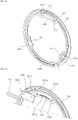
- FIG. 3 is a perspective view of a drum of the washing machine shown in FIG. 1 and a balancer installed in the drum.
- a washing machine 100 includes a cabinet 111 which forms an outer shape, a door 112 which opens and closes one side of the cabinet to allow the cloth to enter and exit the cabinet, a tub 122 disposed inside the cabinet and supported by the cabinet, a drum 124 disposed inside the tub and rotating with a cloth inserted therein, a drum motor 113 which rotates the drum by applying torque to the drum, a detergent box 133 which accommodates detergent, and a control panel 114 which receives a user input and displays a washing machine state.
- the cabinet 111 has a cloth loading hole 111a formed to allow the cloth to enter and exit.
- the door 112 is rotatably coupled to the cabinet 111 to allow the cloth loading hole 111a to be opened and closed.
- the cabinet 111 is provided with the control panel 114.
- the cabinet 111 is provided with a detergent box 133 to be withdrawn.
- the tub 122 is disposed in the cabinet 111 to be buffered by a spring 115 and a damper 117.
- the tub 122 accommodates washing water.
- the tub 122 is disposed in the outside of the drum 124 while surrounding the drum 124.
- the tub 122 includes a cylindrical tub body 122a having both sides opened, a ring-shaped front tub cover 122b disposed in an opened front side of the tub body 122a, and a disk-shaped rear tub cover 122c disposed in an opened rear side of the tub body 122a.
- the front side means the door 112 side
- the rear side means the drum motor 113 side.
- a tub hole 122d is formed in one side of the tub 122.
- the tub hole 122d is formed to communicate with the cloth loading hole 111a to allow the cloth to enter and exit the drum 124.
- the tub hole 122d is formed in the front tub cover 122b.
- a weight 123 is coupled to a portion of one side edge of the tub 122.
- the weight 123 applies a load to the tub 122.
- the weight 123 is preferably disposed around the tub hole 122d.
- a plurality of weights 123 may be provided, and disposed in a portion of upper side and lower side of the front tub cover 122b.
- the plurality of weights 123 includes an upper weight 123a disposed above the front tub cover 122b and a lower weight 123b disposed below the front tub cover 122b.
- the upper weight 123a is disposed above the tub hole 122d among the edge of the tub 122
- the lower weight 123b is disposed below the tub hole 122d among the edge of the tub 122.
- a transmission coil 240 described later may be disposed in the edge of one side of the tub 122.
- the transmission coil 240 wirelessly supplies power to the balancer 300.
- the drum motor 113 generates a rotational force.
- the drum motor 113 may rotate the drum 124 at various speeds or directions.
- the drum motor 113 includes a stator (not shown) wound around with a coil, and a rotor (not shown) that rotates by generating electromagnetic interaction with the coil.
- the drum 124 accommodates the cloth and is rotated.
- the drum 124 is disposed inside the tub 122.
- the drum 124 is formed in a rotatable cylindrical shape.
- the drum 124 is provided with a plurality of through holes so that the washing water can pass.
- the drum 124 rotates while receiving the rotational force of the drum motor 113.
- a drum hole 124a is formed in the front side of the drum 124.
- the drum hole 124a is formed to communicate with the cloth loading hole 111a and the tub hole 122d so that the cloth can be loaded into the drum 124.
- the balancer is coupled to the edge of one side of the drum 124.
- the balancer reduces the unbalance generated by the biasing of the cloth when the drum rotates.
- a gasket 128 seals between the tub 122 and the cabinet 111.
- the gasket 128 is disposed between the opening of the tub 122 and the cloth loading hole 111a.
- the gasket 128 mitigates the shock transmitted to the door 112 when the drum 124 rotates, while preventing the washing water in the tub 122 from leaking to the outside.
- the gasket 128 may be provided with a circulation nozzle 127 for introducing washing water into the drum 124.
- the detergent box 133 accommodates a detergent such as laundry detergent, fabric softener or bleach.
- the detergent box 133 is preferably provided in the front surface of the cabinet 111 to be withdrawn.
- the detergent in the detergent box 133 is mixed with the washing water when the washing water is supplied, and introduced into the tub 122.
- a water supply valve 131 for controlling the inflow of the washing water from an external water source, a water supply flow path 132 through which the washing water introduced into the water supply valve flows into the detergent box 133, and a water supply pipe 134 for introducing washing water mixed with detergent in the detergent box 133 into the tub 122 are provided inside the cabinet 111.
- a drain pipe 135 through which the washing water in the tub 122 is discharged, a pump 136 for discharging the washing water in the tub, a circulation flow path 137 for circulating the washing water, a circulation nozzle 127 for introducing the washing water into the drum 124, and a drain flow path 138 for draining the washing water to the outside are provided inside the cabinet 111.
- the pump 136 may be provided with a circulation pump and a drain pump, and may be connected to the circulation flow path 137 and the drain flow path 138, respectively.
- the balancer 300 is provided in the front side and/or rear side of the drum 124 and, in the present embodiment, is coupled to the edge of the front side of the drum 124.
- the balancer 300 is preferably disposed around the drum hole 124a.
- the balancer 300 moves along the edge of the drum 124 and changes the center of gravity of the drum 124.
- the center of gravity of the drum 124 does not mean the center of gravity of the drum 124 itself, but means a common center of gravity of objects including the drum 124, the cloth accommodated in the drum 124, the balancer 300, and components attached to the drum 124 that rotate together with the drum 124 when the drum 124 rotates.
- the balancer 300 moves along the circumferential direction of the drum 124 to adjust the center of gravity of the drum 124 when the cloth is eccentric.
- vibration and noise are generated due to unbalance in which the geometric center of a rotation axis Ax itself and the actual center of gravity of the drum 124 are not coincident.
- the balancer 300 reduces the unbalance of the drum 124 by allowing the center of gravity of the drum 124 to approach the rotation axis Ax.
- the control panel 114 may include an input unit (not shown) for receiving various operation commands such as a washing course selection, an operation time and reservation for each process through a user, and a display unit (not shown) for displaying the operation state of the washing machine 100.
- the washing machine includes a power supply unit 210 for supplying electric power from the outside, an oscillation unit 220 for generating a voltage fluctuation range in the power supplied from the power supply unit 210, an amplification unit 230 for amplifying the power, a transmission coil 240 for generating a magnetic field, a reception coil 310 for generating power due to electromagnetic induction from a magnetic field, a rectifier 321 for converting a power generated in the reception coil 310 into a direct power, an adjusting unit 322 for adjusting the power into a certain voltage and current, a drive motor 333 for generating power, and a current measuring device for measuring an input current value of the transmission coil 240
- the washing machine may further include a controller for controlling the overall operation of the washing machine, such as the operations of the drive motor 333, the power supply unit 210, and the drum motor 113.
- the power supply unit 210 converts commercial power, which is AC supplied from the outside, into an appropriate power.
- the power supply unit is a switched-mode power supply to convert the commercial power into 14V DC.
- the power supply unit 210 may be provided in a certain position inside the cabinet 111 or in the control panel 114. The power converted and supplied by the power supply unit 210 may also be supplied to the drum motor 113.
- the oscillation unit 220 is an oscillator, and generates a voltage fluctuation range in the power supplied from the power supply unit 210 to generate a magnetic field in the transmission coil 240.
- the amplifier 230 amplifies the power so that the transmission coil 240 can acquire a sufficient current.
- the transmission coil 240 generates a magnetic field
- the reception coil 310 generates power due to electromagnetic induction from the magnetic field in which the transmission coil 240 is generated.
- the current measuring device measures the input current value of the transmission coil 240 to provide to the controller.
- a general ammeter may be used as the current measuring device.
- the rectifier 321 converts the power generated from the reception coil 310 into DC power.
- the adjusting unit 322 adjusts the power rectified by the rectifier 321 into a certain voltage and current.
- the drive motor 333 generates power from the power adjusted by the adjusting unit 322.
- the drive motor 333 generate power from the power that is supplied from the outside and transmitted wirelessly through the transmission coil 240 and the reception coil 310.
- the adjusting unit 322 and the rectifier 321 are disposed in a circuit board 370 described later.
- a storage unit for temporarily storing the power adjusted by the adjusting unit 322 may be provided, and the storage unit (not shown) may be configured of a capacitor or a battery.
- the above-mentioned oscillation unit 220 and amplifier 230 are preferably provided in a certain position inside the cabinet 111 or in the control panel 114, and the reception coil 310, the rectifier 321, the adjusting unit 322, and the drive motor 333 are preferably included in the balancer 300.
- the transmission coil 240 is disposed in the edge of one side of the tub 122 as described above.
- the transmission coil 240 is disposed in the tub 122 to correspond to the movement path of the balancer 300 and wirelessly supplies power to the balancer 300.
- the transmission coil 240 may be disposed in the tub 122 in correspondence with a guide case 340 described later.
- the transmission coil 240 may be formed in an arc shape and disposed in a portion of one side edge of the tub 122, or may be formed in a ring shape and disposed in the entire of one side edge of the tub 122.
- the transmission coil 240 is preferably disposed around the tub hole 122d which is an edge of the front side of the tub 122.
- the transmission coil 240 may be disposed in the front tub cover 122b or the rear tub cover 122c. In the present embodiment, the transmission coil 240 is disposed in the front tub cover 122b. The transmission coil 240 is preferably disposed in the front side of the front tub cover 122b to face a guide rail 125.
- the tub 122 is preferably coupled to a coil cover (not shown) surrounding the transmission coil 240.
- the coil cover (not shown) is coupled to the front tub cover 122b to surround the transmission coil 240.
- the coil cover (not shown) protects the transmission coil 240 from water or foreign matter together with the front tub cover 122b.
- the transmission coil 240 is preferably disposed in the front tub cover 122b in correspondence with the balancer 300.
- the reception coil 310 is provided in one side of the balancer 300 and the transmission coil 240 is disposed to correspond to the reception coil 310.
- the transmission coil 240 is disposed in a portion of the moving path of the reception coil 310 to allow the magnetic field generated in the transmission coil 240 to be converted into power in the reception coil 310.
- the distance between the transmission coil 240 and the reception coil 310 maintains a distance in which power can be transmitted wirelessly.
- the distance between the transmission coil 240 and the reception coil 310 is preferably within 30mm.
- a plurality of transmission coils 240 may be provided.
- the weight 123 is coupled to a portion of the edge of the drum 124.
- the transmission coil 240 is preferably disposed in an area where the weight 123 is not disposed among the edge of one side of the tub 122. At this time, the transmission coil 240 is preferably formed in an arc shape.
- a plurality of weights 123 are provided and disposed in a portion of the upper and lower sides of the front tub cover 122b.
- a plurality of transmission coils 240 are provided in both sides of the front tub cover 122b between the upper weight 123a and the lower weight 123b.
- the balancer 300 may further include at least two drive modules 330 which provide driving force, at least two gear rails 350 which are formed in a ring shape and rotated while being gear-coupled with each drive module 330, at least two balancing weights 360 which move along the circumference of the drum 124 by rotation of each gear rail 350 to change the center of gravity of the drum 124, the reception coil 310 which generates power from a magnetic field formed by the transmission coil, a guide case 340 for receiving at least reception coil 310 and drive module 330, and a coil base which supports the reception coil
- the guide case 340 accommodates at least reception coil 310 and drive module 330.
- the guide case 340 may accommodate the circuit board 370 described later, the balancing weight 360, and the gear rail 350.
- the guide case 340 may be provided in the front side and/or rear side of the drum 124, and in the present embodiment, the guide case 340 is provided in the front side of the drum 124.
- the cloth accommodated in the drum 124 is generally collected in the inner side of the drum 124, i.e., in the rear side. Accordingly, it is preferable that the guide case 340 is provided in the front side of the drum 124 so as to be balanced to the cloth collected in the rear side of the drum 124.
- the drive module 330 and the circuit board 370 are not integrally formed with the balancing weight 360, but separately fixed to the guide case 340, so that the drive module 330 and the circuit board 370 do not move when the balancing weight 360 is moved, thereby reducing damage occurred during movement.
- the guide case 340 has a ring shape corresponding to the circumference of the drum 124, and may have a space in which the balancing weight 360 moves along the circumference of the drum 124, a space for accommodating the drive module 330 and the reception coil 310, and a space for accommodating the gear rail 350.
- the guide case 340 may include a case body 341 and a case cover 342 covering the case body 341.
- the case body 341 is provided with a guide part 341a which is a passage through which the balancing weight 360 passes.
- the guide part 341a is formed by recessing a cross section of the case body 341 downward so that the balancing weight 360 is movable therein.
- the guide part 341a may have a ring shape corresponding to the circumference of the drum 124 so as to guide a path along which the balancing weight 360 moves.
- the guide case 340 may further include a drive module accommodating part 341b and 341c extended from the guide part 341a in the direction of the rotation axis Ax of the drum 124 to accommodate each drive module 330.
- the drive module accommodating part 341b and 341c may be formed by recessing a portion of the case body 341 in the downward direction.
- the drive module accommodating part 341b and 341c may be defined as a recessed area communicating with the guide part 341a.
- the guide case 340 may further include a receiver accommodating part 341f extended from the guide part 341a in the direction of the rotation axis Ax of the drum 124 to place the reception coil 310.
- the receiver accommodating part 341f may be formed by recessing a portion of the case body 341 in a downward direction (see FIG. 4 ).
- the receiver accommodating part 341f may be defined as a recessed area communicating with the guide part 341a.
- reception coil 310 may be accommodated directly in the receiver accommodating part 341f, or the coil base may be installed in the receiver accommodating part 341f, and the reception coil 310 may be installed in the coil base 343.
- the coil base 343 will be described later.
- the guide case 340 may have a support part 341g for supporting the coil base 343 around the guide part 341a.
- the support part 341g may support the coil base 343 and define a gap 21 that is a spaced space between the coil base 343 and the guide case 340.
- the support part 341g may be formed in a part of the edge of the guide part 341a, and in the edge of the receiver accommodating part 341f.
- the case body 341 may include a bottom surface 3411, a flange 3415 positioned above the bottom surface 3411, and an inner surface 3412 and an outer surface 3413 connecting the flange 3415 and bottom face 3411.
- the bottom surface 3411, the inner surface 3412 and the outer surface 3413 together define the receiver portion accommodating portion 341f and the guide part 341a. That is, the bottom surface 3411 forms the bottom surface of the receiver accommodating part 341f and the guide part 341a, and the inner surface 3412 and the outer surface 3413 form a side surface of the receiver accommodating part 341f and the guide part 341a.
- the flange 3415 extended in a direction away from both ends of the bottom surface 3411 at the upper end of each of the inner surface 3412 and the outer surface 3413, thereby providing the case cover 342 and an adhesive surface.
- the flange 3415 is heat-welded with the case cover 342.
- the flange 3415, the inner surface 3412, the outer surface 3413, and the bottom surface 3411 are extended along the circumference respectively.
- the support part 341g may be formed in a portion of the inner surface 3412 and the outer surface 3413 of the case body 341. Alternatively, the support part 341g may be formed in the flange 3415.
- the inner surface 3412 of the case body 341 means a surface closer to the rotation axis Ax of the drum than the outer surface 3413.
- the support part 341g may be a groove formed by recessing the inner surface 3412 and the outer surface 3413 in a downward direction.
- the support portion 341g may be defined as a groove communicating with the guide part 341a and/or the receiver accommodating part 341f.
- An alignment groove 341h to which a fixing protrusion 35 of the coil base 343 is coupled may be formed in the support part 341g.
- the guide case 340 may further include a rail accommodating part 341d extended from the guide part 341a in the direction of the rotation axis Ax of the drum 124 to place the reception coil 310.
- the rail accommodating part 341d may be formed by recessing a portion of the case body 341 in the downward direction.
- the rail accommodating part 341d may be defined as a recessed area communicating with the guide part 341a.
- the rail accommodating part 341d is positioned inside the guide part 341a, and the drive module accommodating part 341b and 341c and the receiver accommodating part 341f are positioned spaced apart from each other inside the rail accommodating part 341d.
- the balancer 300 may further include a circuit board 370 which transmits power of the reception coil 310 to the drive modules 330, and generates a control signal for controlling the drive module 330.
- the manufacturing cost can be reduced by controlling the two drive modules 330 with a single circuit board 370, and the circuit board 370 does not move together with the balancing weight 360, thereby improving reliability.
- the circuit board 370 is accommodated in the guide case 340. In detail, it is accommodated in the receiver accommodating portion 341f of the guide case 340.
- At least a portion of the circuit board 370 and the reception coil 310 may be disposed to be overlapped with each other when viewed in the rotation axis Ax direction of the drum 124. This is because the power generated by the reception coil 310 is transmitted to the circuit board 370 in the shortest distance, thereby reducing the manufacturing cost.
- the drive module 330 provides a driving force.
- the number of drive modules 330 corresponds to the number of balancing weights 360.
- the drive module 330 may include a first drive module 330a and a second drive module 330b.
- Each drive module 330 may include a drive motor 333, a pinion gear 332 engaged with the drive motor 333, and each gear rail 350, and a motor housing accommodating the drive motor 333 and the pinion gear 332.
- the drive motor 333 generates a driving force from the power which is supplied from the outside and is transmitted wirelessly through the transmission coil 240 and the reception coil 310.
- the drive motor 333 is a motor that generates a rotational force.
- the drive motor 333 rotates the pinion gear 332.
- a worm gear is disposed between the motor and the pinion gear 332 so that the rotational force changes the axis of the motor to rotate the pinion gear 332.
- the pinion gear 332 is rotated by receiving power from the drive motor 333.
- a rack gear 351b is disposed in the inner circumferential surface of the gear rail 350, and the pinion gear 332 meshes with the rack gears 351b, 125a.
- the pinion gear 332 rotates by meshing with the rack gears 351b, 125a to rotate the gear rail 350, and when the gear rail 350 rotates, the balancing weight 360 restrained by the gear rail 350 is moved.
- the pinion gear 332 is engaged with the rack gear 351b, 125a to prevent the balancing weight 360 from moving by its own weight or by centrifugal force when the drum 124 rotates.
- the motor housing 331 accommodates the pinion gear and the drive motor 333, and is fixed to the guide case 340.
- the motor housing 331 is fixed to the drive module accommodating part 341b, 341c.
- the reception coil 310 and the first and second drive modules 330 are biased toward one side of the guide case 340, the unbalance of the drum 124 may occur. Accordingly, is preferable that the reception coil 310 and the first and second drive modules 330 are disposed in consideration of the balance of the center of gravity of the drum 124.
- the reception coil 310 and the first and second drive modules 330 are spaced apart from each other on an arbitrary circumference around the rotation axis Ax of the drum 124, the separation distance between the reception coil 310 and the first drive module 330a is the same as the separation distance between the reception coil 310 and the second drive module 330b, and the separation distance between the first drive module 330a and the second drive module 330b may be the same as the separation distance between the reception coil 310 and the first drive module 330a.
- the center angle between the reception coil 310 and the first drive module 330a may be the same as the center angle between the reception coil 310 and the second drive module 330b.
- the center angle between the first drive module 330a and the second drive module 330b may be the same as the center angle between the reception coil 310 and the first drive module 330a.
- the center angle between the reception coil 310 and the first drive module 330a may be referred to as a first center angle ⁇ 1
- the center angle between the reception coil 310 and the second drive module 330b may be referred to as a second center angle ⁇ 2
- the center angle between the first drive module 330a and the second drive module 330b may be referred to as a third center angle ⁇ 3.
- the first center angle means the angle between a line connecting the center of the reception coil 310 and the rotation axis Ax of the drum 124, and a line connecting the center of the first drive module 330a and the rotation axis Ax of the drum 124
- the second center angle means the angle between a line connecting the center of the reception coil 310 and the rotation axis Ax of the drum 124, and a line connecting the center of the second drive module 330b and the rotation axis Ax of the drum 124
- the third center angle means the angle between a line connecting the center of the second drive module 330b and the rotation axis Ax of the drum 124, and a line connecting the center of the first drive module 330a and the rotation axis Ax of the drum 124.
- the first center angle, the second center angle, and the third center angle may be 119 degrees to 121 degrees.
- the gear rail 350 is gear-coupled and rotated with each drive module 330.
- the gear rail 350 may have a ring shape having a diameter smaller than that of the guide part 341a.
- the gear rail 350 may include a ring-shaped rail body 351a, a rack gear 351b formed in an inner circumferential surface of the rail body 351a, and a protrusion 351c that is protruded from the outer circumferential surface of the rail body 351a and restrains the balancing weight 360.
- the rack gear 351b is formed along the inner circumferential surface of the rail body 351a.
- the inner circumferential surface of the rail body 351a means a surface relatively close to the rotation axis Ax of the drum 124 in the rail body 351a
- the outer circumferential surface of the rail body 351a means a surface positioned farther from the rotation axis (Ax) of the drum 124 than the outer circumferential surface of the rail body 351a in the rail body 351a.
- the inner circumferential surface of the rail body 351a and the outer circumferential surface of the rail body 351a may be disposed to face each other.
- the inner circumferential surface of the rail body 351a and the outer circumferential surface of the rail body 351a are disposed to surround the rotation axis Ax of the drum 124.
- the gear rail 350 may be provided to correspond to the number of drive modules 330.
- the gear rail 350 includes a first gear rail 351 and a second gear rail 352.
- the first gear rail 351 is rotated by the driving force of the first drive module 330a
- the second gear rail 352 is rotated by the driving force of the second drive module 330b.
- the rack gear 351b of the first gear rail 351 is engaged with the pinion gear 332 of the first drive module 330a
- the rack gear 351b of the second gear rail 352 is engaged with the pinion gear 332 of the second drive module 330b.
- the gear rail 350 may be accommodated in the rail accommodating part 341d.
- the gear rail 350 may rotate while sliding in the rail accommodating part 341d.
- the two gear rails 350 may be positioned at different heights.
- the first gear rail 351 and the second gear rail 352 may be disposed to be overlapped in the direction of the central axis of the drum 124. In FIG. 4 , the first gear rail 351 is disposed above the second gear rail 352.
- the balancing weight 360 moves along the circumference of the drum 124 by the driving force of the drive module 330.
- the balancing weight 360 moves along the circumference of the drum 124 by the rotation of each gear rail 350 to change the center of gravity of the drum 124.
- At least two balancing weights 360 are provided, and each balancing weight 360 is restrained by each gear rail 350.
- the balancing weight 360 may include a first balancing weight 360 and a second balancing weight 360.
- the balancing weight 360 may include a balancing body 361 having a coupling groove 361a coupled to the gear rail 350, and a roller 362 coupled to the balancing body 361.
- the balancing body 361 may include an object having a weight or mass.
- the balancing body 361 has an arc shape, and a coupling groove 361a may be formed in a surface facing the outer circumferential surface of the gear rail 350.
- the protrusion 351c of the gear rail 350 is inserted into the coupling groove 361a.
- the protrusion 351c is inserted into the coupling groove 361a of the balancing body 361, so that the movement of the balancing body is restrained by the rotation of the gear rail 350.
- the roller 362 is provided in the balancing body 361 so as to be rotatable.
- the roller 362 is in close contact with the inner surface of the guide part 341a and is rolled.
- the roller 362 prevents the balancing body 361 from directly touching the inner surface of the guide part 341a. It is preferable that a plurality of rollers 362 are provided in both ends of the balancing body 361.
- each drive module 330 is positioned inside an arbitrary circumference formed by the gear rail 350, and each balancing weight 360 is positioned outside of an arbitrary circumference formed by the gear rail 350 in terms of utilization of space.
- the reception coil 310 should be wired to the circuit board 370, it should be disposed close to the circuit board 370. In addition, the reception coil 310 should be positioned to avoid interference with the balancing weight 360 moving along the circumference.
- the reception coil 310 should be stably fixed when the guide case 340 is heat-welded. Accordingly, the coil base 343 is used so that the reception coil 310 is stably positioned to be close to the circuit board 370 and not to be interfered by the balancing weight 360.
- the coil base 343 is accommodated in the guide case 340 and supports the reception coil 310.
- the coil base 343 is disposed at a different height from the balancing weight 360, such that the reception coil 310 supported on the coil base 343 is disposed at a different height from the balancing weight 360.
- the coil base 343 may be disposed at a height higher than the balancing weight 360, and the reception coil 310 may be disposed above the coil base 343.
- the height reference is an up and down direction in FIG. 5C .
- a higher one is positioned in a relatively upward direction, and a low one is positioned in a relatively downward direction.
- the circuit board 370 When the circuit board 370 is disposed at a different height from the balancing weight 360, the thickness of the balancer becomes too thick. Accordingly, preferably, the circuit board 370 and the balancing weight 360 are disposed at the same height. Since the reception coil 310 should be positioned close to the circuit board 370, at least a part of the reception coil 310 overlaps with the circuit board 370 in the upper portion of the circuit board 370 of the reception coil 310.
- the coil base 343 may be disposed at a different height from the circuit board 370.
- the coil base 343 may be positioned in the upper portion of the circuit board 370, and the reception coil 310 may be disposed in the upper portion of the coil base 343. Therefore, the thickness of the balancer can be reduced while adjoining the circuit board 370 and the reception coil 310.
- the reception coil 310 may be disposed at a different height from the drive module 330.
- the reception coil 310 may be disposed at a height higher than that of the drive module 330.
- the drive module 330 may be positioned at the same height as the circuit board 370 or the balancing weight 360.
- the coil base 343 may be positioned above the receiver accommodating part 341f and the guide part 341a. That is, the coil base 343 may be supported by the upper end of the case body 341 while covering at least a portion of the guide part 341a and a portion of the receiver accommodating part 341f. Preferably, the coil base 343 may be supported by the support part 341g of the case body 341.
- the coil base 343 may be configured to prevent the inflow of slag into the receiver accommodating part 341f and the guide part 341a, be fixed to the guide case 340 before heat-welding, and support the reception coil 310.
- the base plate 31 may include a base plate 31, an alignment protrusion 32, an overflow preventing surfaces 33, 34, and a fixing protrusion 35.
- the base plate 31 supports the reception coil 310.
- the base plate 31 may have a larger area than at least the reception coil 310.
- the overflow preventing surface 33, 34 may be extended in a direction intersecting the extension direction of the base plate 31 from both ends of the base plate 31.
- the base plate 31 is extended in the horizontal direction, and the overflow preventing surface 33, 34 may be extended in the up and down direction from the inner and outer ends of the base plate 31.
- the inner end is an end closer to the rotation axis Ax of the drum than the outer end.
- the overflow preventing surface 33, 34 is supported by the support part 341g, so that the base plate 31 is positioned above the receiver accommodating part 341f and the guide part 341a.
- the overflow preventing surface 33, 34 may define a gap 21 in which slag is collected between the guide case 340 and the overflow preventing surface 33. That is, the gap 21 is a separation space formed between one surface of the coil base 343 and at least three surfaces of the guide case 340, and prevents the slag, which is generated when the case body 341 and the case cover 342 are heat-welded, from flowing into the guide part 341a and the receiver accommodating part 341f.
- the width of the overflow preventing surface 33, 34 is formed smaller than the width of the support part 341g, and the gap 21 is positioned farther from the base plate 31 than the overflow preventing surface 33, 34.
- the gap 21 may be positioned in the flange 3415.
- the fixing protrusion 35 protrudes from the base plate 31 to determine the position of the base plate 31.
- the fixing protrusion 35 protrudes downward from the lower end of the overflow preventing surface 33, 34 to be coupled to the alignment groove of the case body 341.
- the fixing protrusion 35 protrudes in the opposite direction to the alignment protrusion 32.
- the alignment protrusion 32 protrudes upward from the base plate to determine the position of the reception coil 310.
- Two alignment protrusions 32 may be disposed spaced apart from each other, and the reception coil 310 may be disposed to surround the alignment protrusions 32.
- the melting point of the coil base 343 may be the same as the guide case 340 or higher than the guide case 340. Preferably, the melting point of the coil base 343 may be higher than the guide case 340. This is because if the melting point of the coil base 343 is higher than the guide case 340, the coil base 343 does not melt during heat-welding of the guide case 340, and the inflow of slag can be effectively prevented.
- the noise and vibration of the washing machine may occur when the drum is rotated, particularly, in a dehydration process where the drum is rotated at high speed.
- the driving of the drum in the dehydration process will be described.
- FIG. 9 is a flowchart illustrating a dehydration process according to an embodiment of the present invention
- FIG. 10 is a graph showing the rotational speed of a drum in the dehydration process of FIG. 9 .
- the horizontal axis indicates time
- the vertical axis indicates the rotational speed of the drum 30, i.e., the change of RPM.
- the dehydration process may briefly include a cloth dispersion step S100 and a dehydration step S200.
- the drum 124 may be rotated at a relatively low speed to evenly disperse the cloth.
- the drum 124 may be rotated at a relatively high speed to remove moisture of the laundry.
- the cloth dispersion step and the dehydration step are named based on their main function, and the function in each step is not limited depending on the name.
- water may be removed from the cloth by the rotation of the drum 124, in addition to the cloth dispersion.
- the cloth dispersion step S100 may include a step of detecting the eccentricity of the drum 124 and releasing the eccentricity of the drum 124 by the balancer.
- a controller 260 may first detect the cloth amount inside the drum 124, i.e., the amount of wet cloth (S110).
- the reason for detecting the amount of wet cloth is that the weight of the water-containing cloth is different from the weight of the dry cloth even if the amount of non-wet amount, i.e., the amount of dry cloth, is detected at the initial stage of the washing process.
- the detected amount of wet cloth serves as a factor that determines a permission condition for accelerating the drum 124 in a transient area passing step S210 described later, or determines to perform the cloth dispersion step again by decelerating the drum 124 by the eccentric condition in the transient area passing step S210.
- the amount of wet cloth inside the drum 124 may be measured when the drum 124 is accelerated to a first rotational speed (a first RPM), e.g., about 100 to 110 RPM to drive at a constant speed for a certain time and is decelerated. Power generation braking may be used when the drum 124 is decelerated.
- the amount of wet cloth can be detected by using the amount of rotation in an acceleration section during acceleration of the drive motor 40 for rotating the drum 124, the amount of rotation in a deceleration section during deceleration, an applied motor DC power, and the like.
- the position of the balance weights 360 of the balancer is detected, and a plurality of balancing weights 360 have the same phase difference (phase difference between two balancing weights 360 is 180°). Detecting the position of the balancing weight 360 will be described later.
- the controller 260 may perform a cloth untangling step for the cloth dispersion inside the drum 124 (S130).
- the cloth untangling step intends to evenly disperse the cloths inside the drum 124 so as to prevent the cloths from being concentrated in a specific area inside the drum 124 and increasing the amount of eccentricity of the drum 124. This is because noise and vibration increase when the RPM of the drum 124 is increased if the amount of eccentricity is increased.
- the cloth untangling step may be performed until the drum 124 is accelerated in one direction by a certain inclination and reaches the rotation speed of an eccentric detection step described later.
- the controller 260 may detect an eccentricity of the drum 124 (S150).
- S150 an eccentricity of the drum 124
- the controller 260 may determine whether to accelerate the drum 124 by detecting the eccentric amount of the drum 124.
- Eccentricity detection may be performed by using an acceleration difference when the drum 124 rotates. That is, depending on the degree of eccentricity, when the drum 124 rotates, there is a difference in acceleration between a case where the drum 124 rotates downward according to the gravity and a case where the drum 124 rotates upward in the opposite direction to the gravity.
- the controller 260 may measure the acceleration difference by using a speed sensor such as a hall sensor provided in the drive motor 40, and may detect an eccentric amount by the detected acceleration difference.
- the controller 260 may store the data, in the form of a table, in which a reference amount of eccentricity permitting acceleration is previously determined according to the amount of wet cloth. Therefore, it is possible to determine whether to accelerate by applying the detected amount of wet cloth and amount of eccentricity to the table.
- the amount of eccentricity may be reduced by repeating the above-described wet cloth detection step, the cloth untangling step, the eccentric detection step or by moving the position of the balancing weight 360.
- the eccentricity reduction step by using the balancer may include a step of minimizing the phase difference between two or more balancing weights 360. That is, prior to moving the two or more balancing weights 360 to minimize the eccentricity, firstly, the phase difference between the balancing weights 360 may be minimized, for example, the balancing weights 360 may be connected to each other. This is because when two or more balance weights 360 are provided and, if they are moved individually, it is time-consuming and complicated to reduce the amount of eccentricity.
- the position of the balancing weight 360 may be determined based on the amount of change in the input current value of the transmission coil 240.
- the controller 260 may move the balancing weights 360 in opposite directions, and when the distance between the balancing weights 360 is minimized, the movement of the balancing weight 360 may be stopped to minimize the phase difference.
- the eccentric amount of the drum 124 is detected while moving the two or more balancing weights 360 to be relatively moved with respect to the drum 124. That is, when the drum 124 rotates at a certain rpm, for example, a rpm (a case where the drum 124 rotates at a rotational speed of about 100 to 110 RPM) at which the cloth inside the drum 124 does not fall and is attached to the inner wall of the drum 124, the balancing weight 360 moves relatively with respect to the drum 124 and moves along the inside of the housing. In this case, the amount of eccentricity of the drum 124 may be reduced when the balancing weight 360 moves approximately to an eccentric corresponding position. Therefore, the controller 260 detects an eccentric amount of the drum 124 according to the movement of the balancing weight 360.
- a rpm a case where the drum 124 rotates at a rotational speed of about 100 to 110 RPM
- the controller 260 may stop the movement of the balancing weight 360 at a first position where a first minimum value of the eccentricity of the drum 124 is detected.
- the controller 260 may store the minimum value as the first minimum value when the minimum value of the eccentricity is detected according to the movement of the balancing weight 360.
- the position of the balancing weight 360 in which the first minimum value is detected may be stored as the first position. Since the first minimum value corresponds to the minimum value of the eccentricity when the balancing weights 360 move in a minimum phase, i.e., in a connected state with each other, the controller 260 moves the balancing weight 360 to the first position to fix the position.
- the first position may be changed according to various factors such as the dispersion of the cloth inside the washing machine, the cloth amount, the installation position of the balancer, and the like, and may correspond to an approximately eccentric corresponding position.
- the eccentricity of the drum 124 can be further reduced than the first minimum value. That is, since the first minimum value is a value detected when two or more balancing weights 360 have a minimum phase difference (or state of being connected with each other), each of the two or more balancing weights 360 is moved from the first position where the first minimum value is detected, the amount of eccentricity can be reduced to a value smaller than the first minimum value.
- the acceleration permission condition is satisfied, so that the subsequent transient area passing step S210 may be performed.
- the transient area may be defined as a certain RPM band including one or more resonance frequencies in which resonance occurs according to a system of a washing machine.
- the transient area is an inherent vibration characteristic that occurs according to a determined system when the system of the washing machine is determined.
- the transient area is changed according to the system of the washing machine and, for example, may have a range of approximately 200 to 350 RPM.
- the rotational speed of the drum 124 passes through the transient area, resonance occurs in the washing machine, and the noise and vibration of the washing machine may be significantly increased.
- noise and vibration cause discomfort to the user, and further, disturb the acceleration of the drum 124.
- the acceleration slope may be adjusted appropriately to reduce the noise and vibration when accelerating the drum 124.
- the controller 260 can continue to detect the amount of eccentricity of the drum 124.
- the controller 260 may be provided with a vibration sensor in the drum 124 of the washing machine and may detect the vibration of the drum 124 when passing through the transient area. If the detected vibration and/or amount of eccentricity of the drum 124 in the transient area passing step becomes larger than a certain value, the controller 260 decelerates the drum 124 to repeat the above-described wet cloth detection step, the cloth untangling step, and the eccentric detection step, or to execute the eccentric detection step and the eccentricity reduction step S170 using the balancer described above.
- the controller 260 may perform a water extraction step (S230).
- the controller 260 removes water from a washing object by maintaining the rotational speed of the drum 124 at a second RPM (S200).
- the drum 124 is accelerated to a relatively high speed up to a desired RPM and maintained to extract the water.
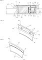
- FIGS. 11A to 11D shows each part of a balancer relatively moving with respect to a transmission coil 240 when the drum 124 rotates
- FIG. 12A is a graph illustrating a change in an input current value of a transmission coil over time according to an embodiment of the present invention
- FIG. 12B is a graph illustrating a change in an input current value of a transmission coil over time according to another embodiment of the present invention.
- FIG. 12A is a graph illustrating a change in an input current value of a transmission coil for each unit time according to one rotation of the drum 124 when the drive motor 300 of the drive module 330 is turned off.
- FIG. 12B is a graph illustrating a change in the input current value of the transmission coil for each unit time according to one rotation of the drum 124 when the drive motor 300 of the drive module 330 is turned on.
- the input current value of the transmission coil 240 is changed.
- the transmission coil 240 is adjacent to (or overlapped with) the reception coil 310, the input current value of the transmission coil 240 is changed rapidly because power is transmitted to the reception coil 310, and when the transmission coil 240 is adjacent to other member, the change of the input current value of the transmission coil 240 becomes small.
- the transmission coil 240 is adjacent to a certain configuration' means that the transmission coil 240 is vertically overlapped with a certain configuration in the direction of the rotation axis of the drum 124 and is very close to each other. In this case, other configurations are spaced apart from the transmission coil 240 without being vertically overlapped with the transmission coil 240.
- the input current value of the transmission coil 240 becomes a reference current value C0.
- the reference current value C0 may be a value preset by an experiment, or may be an average current value of a section A5 having a rate of change of a certain time or less in an input current value curve.
- the guide case 340 is preferably formed of a resin material so as to change the input current value of the transmission coil 240 a little.
- the input current value of the transmission coil 240 has a larger value than the reference current value C0, and has a value smaller than a maximum current value (Cmax). Since the drive module 330 has a material including magnetism, it changes the input current value of the transmission coil 240.
- the input current value of the transmission coil 240 has an intermediate current value that is larger than the reference current value C0 and smaller than the maximum current value (Cmax).
- the intermediate current value may be a value larger than the input current value of the transmission coil 240 when the transmission coil 240 is adjacent to the drive module 330.
- the balancing weight 360 may have a larger mass, a larger volume, and a larger length than the drive module 330. Since the balancing weight 360 has a larger mass and size than the drive module 330, it is easy to distinguish the balancing weight 360 from the drive module 330 on an input current curve. More preferably, the balancing weight 360 may contain a metal, or may contain a metal and a material including magnetism.
- the input current value of the transmission coil 240 is decreased than the reference current value C0 as shown in FIG. 12A .
- the input current value of the transmission coil 240 has a minimum current value Cmin, when the transmission coil 240 is adjacent to (or overlapped with) the reception coil 310 and the drive motor 300 is in an off state.
- the rate of change of the input current value of the transmission coil 240 is maximized.
- the input current value of the transmission coil 240 is increased larger than the reference current value C0 as shown in FIG. 12B .
- the input current value of the transmission coil 240 has a maximum current value Cmax when the transmission coil 240 is adjacent to (or overlapped with) the reception coil 310 and the drive motor 300 is in an on state.
- the position of the configuration fixed to the drum 124 may be determined based on the input current value of the transmission coil 240, and the position of the balancing weight 360 may be determined as a relative phase difference in the configuration fixed to the drum 124.
- the relative position of the balancing weights 360 is determined based on the reception coil 310. However, it is not limited thereto, and the position of the balancing weight 360 may be calculated based on the drive module 330.
- the controller 260 determines the position of the balancing weight 360 based on the input current value when the drum 124 rotates, while power is supplied to the transmission coil 240.
- the controller 260 may vary the method of determining the position of the balancing weight 360 according to the on or off state of the drive motor 300.
- the controller 260 controls an ammeter to measure the input current value for each unit time during at least one rotation of the drum 124, and may determine a first time point at which the input current value becomes less than or equal to a preset first current value as the position of the reception coil.
- the first current value may be 0.5 times to 0.7 times the reference current value C0.
- the first time point may be set as a reference time point and, at this time, the position of the reception coil 310 may be defined as a reference position (0°).
- the first current value may be set smaller than the reference current value.
- the intermediate time point of a section A6 in which the input current value becomes less than or equal to a preset first current value may be defined as the first time point.
- the controller 260 determines a second time point at which the input current value is equal to or greater than a preset second current value, and may determine a phase difference between the reception coil and the balancing weight 360 based on a time difference between the first time point and the second time point.
- the second current value may be 1.1 times to 1.2 times the reference current value C0.
- the second current value may be set to a value larger than the input current value when the drive module 330 is adjacent to the transmission coil 240.
- an intermediate time point of sections A2 and A3 in which the input current value becomes greater than or equal to the second current value may be defined as the second time points.
- the operation of determining the phase difference between the reception coil and the balancing weight 360 based on the time difference between the first time point and the second time point may be calculated by multiplying a value obtained by dividing the time difference between the first time point and the second time point by one rotation time of the drum 124 by 360°. Accordingly, the relative position of the first balancing weight 360 and the second balancing weight 360 can be accurately calculated.
- the controller 260 may calculate an input current curve showing a change in the input current value over time during at least one rotation of the drum 124, and may determine the minimum point (C min) (within one period) of the input current value on the input current curve as the position of the reception coil.
- the controller 260 selects a band section in which the input current value becomes greater than or equal to the preset reference current value C0.
- the controller 260 may distinguish the balancing weight 360 from the drive module 330 by a width (time) of the band section on the input current curve.
- the controller 260 determines the band section A2, A3 as the position of the balancing weight 360 when the width of the band section is larger than a preset width, and determines the band section A1 as the position of the drive module 330 when the width of the band section is smaller than the preset width.
- the controller 260 may determine a phase difference between the reception coil and the balancing weight 360 based on a distance difference (in time axis) (or time difference) between the minimum point (Cmin) of the input current value and the peak of the band section A2, A3.
- the calculation of the phase difference based on the time difference or the distance difference is the same as described above.
- the controller 260 controls the ammeter to measure the input current value for each unit time during at least one rotation of the drum 124, and may determine a third time point at which the input current value is greater than or equal to a preset third current value as the position of the reception coil.
- the third current value may be 1.3 times to 1.5 times the reference current value C0.
- the drum 124 is rotated at a constant speed.
- the third current value may be set larger than the reference current value.
- the intermediate time point of a section A4 in which the input current value becomes greater than or equal to the preset third current value may be defined as the third time point.
- the controller 260 determines a second time point at which the input current value is greater than or equal to the preset second current value and is less than or equal to the third current value, and may determine a phase difference between the reception coil and the balancing weight 360 based on the time difference between the third time point and the second time point.
- the second current value may be set to a value larger than the input current value when the drive module 330 is adjacent to the transmission coil 240.
- the second current value is set to a value smaller than the third current value.
- an intermediate time point of the section A2, A3 in which an input current value is greater than or equal to the second current value and less than or equal to the third current value may be defined as the second time points.
- the operation of determining the phase difference between the reception coil and the balancing weight 360 based on the time difference between the first time point and the second time point may be calculated by multiplying a value obtained by dividing the time difference between the first time point and the second time point by one rotation time of the drum 124 by 360°.
- the controller 260 may calculate an input current curve showing a change in the input current value over time during at least one rotation of the drum 124, and may determine the maximum point (C max) (within one period) of the input current value on the input current curve as the position of the reception coil.
- the controller 260 selects a band section in which the input current value is greater than or equal to the preset reference current value C0 and smaller than the second current value.
- the controller 260 may distinguish the balancing weight 360 from the drive module 330 by a width (time) of the band section on the input current curve.
- the controller 260 determines the band section A2, A3 as the position of the balancing weight 360 when the width of the band section is larger than a preset width, and determines the band section A1 as the position of the drive module 330 when the width of the band section is smaller than the preset width.
- the controller 260 may determine a phase difference between the reception coil and the balancing weight 360 based on a distance difference (in time axis) (or time difference) between the maximum point (Cmax) of the input current value and the peaks of the band section A2, A3.
- the controller 260 specifies the position of the balancing weight 360 by the input current value of the transmission coil 240, it is not necessary to mount a plurality of sensors to specify the position of the balancing weight 360, but the burden on the controller 260 can be reduced by a simple operation.
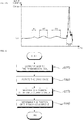
- FIG. 13 is a flowchart illustrating a control method according to an embodiment of the present invention.
- the control method of the washing machine for determining the position of the balancing weight 360 of the present invention may include a step (a) of supplying power to the transmission coil 240 (S310), a step (b) of rotating the drum 124 at least once (S320), a step (c) of measuring the change in the input current value of the transmission coil 240 for each unit time during one rotation of the drum 124 (S330), and a step (d) of determining the position of the balancing weight 360 based on the change in the input current value (S340).
- the control method of the washing machine for determining the position of the balancing weight 360 of the present invention can be accomplished at any step of the washing process described above.
- the controller 260 controls the power supply unit 210 to supply power to the transmission coil 240 (S310).
- controller 260 controls the drum motor 113 in a state in which power is supplied to the transmission coil 240 to rotate the drum 124 at least once (S320).
- controller 260 controls the ammeter to measure the change in the input current value of the transmission coil 240 for each unit time during one rotation of the drum 124 (S330).
- the controller 260 determines the position of the balancing weight 360 based on the change in the input current value (S340).
- the controller 260 may determine the minimum point (C min) (within one period) of the input current value as the position of the reception coil. More specifically, the controller 260 calculates an input current curve showing a change in the input current value over time during at least one rotation of the drum 124, and may determine the minimum point (C min)(within one period) of the input current value, on the input current curve, as the position of the reception coil.
- step (d) a band section in which the input current value becomes equal to or greater than the preset reference current value C0 is selected.
- the controller 260 may distinguish the balancing weight 360 from the drive module 330 by the width (time) of the band section on the input current curve. In detail, when the width of the band section is greater than the preset width, the controller 260 determines the band section A2, A3 as the position of the balancing weight 360. Then, the controller 260 may determine a phase difference between the reception coil and the balancing weight 360 based on the distance difference (in time axis) (or time difference) between the minimum point (Cmin) of the input current value and the peak of the band section A2, A3.
- the controller 260 may determine the maximum point (C max) (within one period) of the input current value as the position of the reception coil.
- the controller 260 may calculate an input current curve showing a change in the input current value over time during at least one rotation of the drum 124, and may determine the maximum point (C max) (within one period) of the input current value on the input current curve as the position of the reception coil. Then, the controller 260 selects a band section in which the input current value is greater than or equal to the preset reference current value C0 and smaller than the second current value.
- the controller 260 may distinguish the balancing weight 360 from the drive module 330 by a width (time) of the band section on the input current curve.
- the controller 260 determines the band section A2, A3 as the position of the balancing weight 360 when the width of the band section is larger than a preset width. Then, the controller 260 may determine a phase difference between the reception coil and the balancing weight 360 based on a distance difference (in time axis) (or time difference) between the maximum point (Cmax) of the input current value and the peaks of the band section A2, A3.
- a wireless power transmitter can wirelessly transmit sufficient power to the balancer in a short time.
- the balancing weight that actively moves, the drive module, and the reception coil are separated from each other, and the drive module and the balancing weight are not manufactured integrally, so that manufacturing is easy and manufacturing cost is reduced.
- the interference of the balancing weight moving along the circumference with the reception coil can be eliminated, and the circuit board is positioned close to the reception coil.
- the position of the balancing weight can be accurately measured only by the input current value of the transmission coil, without the need to add a plurality of sensors.
- the reception coil is positioned to be higher than the circuit board and the balancing weight by using the coil base, and the slag generated during heat-welding of the guide case can be prevented from overflowing into the moving path of the balancing weight.
- each drive module and the circuit board for controlling each drive module and supplying power are separated from each other and a single circuit board and a single reception coil are used, so that manufacturing cost is reduced, and the reliability is improved as the drive module does not move together with the balancing weight.
Abstract
Description
- The present invention relates to a washing machine for determining the position of a balancer that is actively movable, and a control method of the washing machine.
- In general, a washing machine is an apparatus that performs cleaning through a process such as washing, rinsing, dehydrating, and the like to remove contamination on clothes, bedding, etc. (hereinafter, referred to as 'cloth') by using water, detergent, and mechanical action.
- Washing machines are classified into agitator type, pulsator type, and drum type washing machines.
- The agitator type washing machine performs washing by rotating a laundry rod towering in the center of the washing tub from side to side, the pulsator type washing machine rotates a disk-shaped rotary blades formed in the lower portion of the washing tub from side to side to perform washing by using frictional force between the water flow and the cloth, and the drum type washing machine performs washing by putting water, detergent, and cloth into the drum, and rotating the drum.
- The drum washing machine is provided with a tub, a drum, a motor, and a drive shaft. The tub, in which washing water is accommodated, is provided inside a cabinet forming an outer shape. The drum, which accommodates a cloth, is disposed inside the tub. The motor is mounted in the rear surface side of the tub so as to rotate the drum. The drive shaft which penetrates through the motor and is connected to the rear surface side of is built up in the drum. The inside of the drum is equipped with a lifter to lift the cloth when the drum rotates.
- Such a washing machine has a phenomenon in which the cloth is biased to one side due to the entanglement of the cloth, which causes an eccentricity in which one side becomes heavy based on the center of the drum. When the cloth is eccentric and the drum rotates at high speed (e.g., when the cloth is dehydrated), vibration and noise are generated by unbalance where the geometric center of the drum's rotation axis itself and the actual center of gravity are not coincident. An apparatus, which is called a balancer, for reducing the unbalance of the drum is installed in order to reduce such vibration and noise.
- A counter weight for counterbalancing eccentricity by attaching additional mass has been used as a balancer for drum type washing machines. Recently, as shown in Korean Utility Model Publication No.
1998-019360 - Such a ball balancer scheme has a problem in that it can not correctly resolve the unbalance actively.
- In addition, there is a problem in that, in order to actively move the balancer to solve the unbalance, the eccentricity must be detected or the position of the balancer must be accurately detected while the eccentricity is solved.
- A position sensor of the balancer has errors and failures that frequently occur, and if a large number of position sensors are not used, accurate detection is difficult. Accordingly, there is a problem of increasing unbalance in the balancing of the washing machine operation.
- The present invention has been made in view of the above problems, and provides a washing machine which actively moves to actively eliminate the unbalance, and a control method of the washing machine.
- The present invention further provides a balancer and a washing machine which can operate by wireless power, have a simple structure, and can reduce the number of parts.
- The present invention further provides a balancer and a washing machine which are stably fixed at the time of heat-welding of a guide case while a reception coil does not interfere with a moving balancing weight.
- The present invention further provides a washing machine which can determine the position of the balancing weight moving along the circumference of the drum without a separate sensor, and a control method of the washing machine.
- In order to achieve the above object, the present invention determines the position of the balancing weights based on the input current value of the transmission coil when the drum rotates.
- In detail, the washing machine of the present invention includes: a tub for accommodating washing water; a transmission coil which is provided in the tub and transmits power wirelessly by generating a wireless power signal; an ammeter which measures an input current value of the transmission coil; a cylindrical drum which is disposed inside the tub to accommodate cloth and is rotatable; a balancer for reducing unbalance generated by a biasing of the cloth during rotation of the drum; and a controller for controlling the ammeter and the balancer, wherein the balancer includes; a reception coil which is provided in the drum and generates power from a magnetic field formed by the transmission coil; at least two drive modules which are driven by the power of the reception coil and provided in the drum; and at least one balancing weight which moves along a circumference of the drum by a driving force of each drive module, and changes a center of gravity of the drum, wherein the controller determines a position of the balancing weights based on the input current value when the drum rotates.
- Preferably, the controller may control the ammeter to measure an input current value for each unit time during at least one rotation of the drum.
- Preferably, the controller may determine a first time point at which the input current value is equal to or less than a preset first current value as a position of the reception coil.
- Preferably, the controller may detect a second time point at which the input current value is equal to or greater than a preset second current value.
- Preferably, the controller may determine a phase difference between the reception coil and the balancing weight based on a time difference between the first time point and the second time point.
- Preferably, the controller may control the ammeter to measure the input current value for each unit time during at least one rotation of the drum.
- Preferably, the controller may determine a third time point at which the input current value becomes equal to or greater than a preset third current value as a position of the reception coil.
- Preferably, the controller may detect a second time point at which the input current value is equal to or greater than a preset second current value and is less than or equal to the third current value
- Preferably, the controller may determine a phase difference between the reception coil and the balancing weight based on a time difference between the third time point and the second time point.
- Preferably, the controller may determine a minimum point of the input current value, on an input current curve showing a change in the input current value over time during at least one rotation of the drum, as a position of the reception coil, and determines a band section in which the input current value is equal to or greater than a preset reference current value as the position of the balancing weight.
- Preferably, the controller may determine as a position of the drive module, when a width of the band section is smaller than a preset width.
- Preferably, the controller may determine a phase difference between the reception coil and the balancing weight based on a time difference between the minimum point of the input current value and a peak of the band section.
- Preferably, the controller may determine a maximum point of the input current value, on an input current curve showing a change in the input current value over time during at least one rotation of the drum, as a position of the reception coil, and determines a band section in which the input current value becomes a value between a preset reference current value and a preset second current value, as a position of the balancing weight.
- Preferably, the controller may determine as a position of the drive module, when a width of the band section is smaller than a preset width.
- Preferably, the controller may determine a phase difference between the reception coil and the balancing weight based on a time difference between the maximum point of the input current value and a peak of the band section.
- The method of controlling a washing machine of the present invention may include the steps of: (a) supplying power to a transmission coil; (b) rotating a drum at least once; (C) measuring a change in an input current value of the transmission coil for each unit time during one rotation of the drum; and (d) determining a position of a balancing weight based on the input current value.
- The step (d) may include determining a minimum point of the input current value as a position of a reception coil.
- The step (d) may include determining a band section in which the input current value is equal to or greater than a preset reference current value as a position of a balancing weight.
- The step (d) may include determining a phase difference between the reception coil and the balancing weight based on a time difference between the minimum point of the input current value and a peak of the band section.
- The step (d) may include determining a maximum point of the input current value as a position of a reception coil.
- The step (d) may include determining a band section in which the input current value becomes a value between a preset reference current value and a preset second current value, as the position of the balancing weight.
- The step (d) may include determining a phase difference between the reception coil and the balancing weight based on a time difference between the maximum point of the input current value and a peak of the band section.
- The above and other objects, features and advantages of the present invention will be more apparent from the following detailed description in conjunction with the accompanying drawings, in which:
-
FIG. 1A is a cross-sectional view of a washing machine according to an embodiment of the present invention; -
FIG. 1B is a block diagram of the washing machine shown inFIG. 1A ; -
FIG. 2 is a perspective view of a tub of the washing machine shown inFIG. 1 ; -
FIG. 3 is a perspective view of a drum of the washing machine shown inFIG. 1 and a balancer installed in the drum; -
FIG. 4 exploded perspective view of a balancer acc. to an embodiment of the present invention; -
FIG. 5A is a perspective view of a balancer according to an embodiment of the present invention; -
FIG. 5B is a partially exploded perspective view of a balancer according to an embodiment of the present invention; -
FIG. 5C is a cross-sectional view of a balancer acc. to an embodiment of the present invention; -
FIG. 5D is a perspective view of a coil base from one direction according to an embodiment of the present invention; -
FIG. 5E is a perspective view of a coil base from another direction according to an embodiment of the present invention; -
FIG. 6 is a plan view of a balancer according to an embodiment of the present invention; -
FIG. 7 is a perspective view of a drive module acc. to an embodiment of the present invention; -
FIG. 8 is a perspective view of a balancing weight acc. to an embodiment of the present invention; -
FIG.9 a flowchart illustrating a dehydration process acc. to an embodiment of the present invention; -
FIG. 10 is a graph showing the rotational speed of a drum in the dehydration process ofFIG. 9 ; -
FIGS. 11A to 11D shows each part of a balancer relatively moving with respect to a transmission coil when the drum rotates; -
FIG. 12A is a graph illustrating a change in an input current value of a transmission coil over time according to an embodiment of the present invention; -
FIG. 12B is a graph illustrating a change in an input current value of a transmission coil over time according to another embodiment of the present invention; and -
FIG. 13 is a flowchart illustrating a control method according to an embodiment of the present invention. - Exemplary embodiments of the present invention are described with reference to the accompanying drawings in detail. The same reference numbers are used throughout the drawings to refer to the same or like parts. Detailed descriptions of well-known functions and structures incorporated herein may be omitted to avoid obscuring the subject matter of the present invention. As used herein, the singular form is intended to include the plural forms as well, unless the context clearly indicates otherwise. In the present application, it will be further understood that the terms "comprises", includes," etc. specify the presence of stated features, integers, steps, operations, elements, components, or combinations thereof, but do not preclude the presence or addition of one or more other features, integers, steps, operations, elements, components, or combinations thereof. Unless defined otherwise, the terms including technical and scientific terms used in this specification may have the meaning that can be commonly apprehended by those skilled in the art. The terms, such as the terms defined in the commonly-used dictionary, must be interpreted based on the context of the related technology and must not be interpreted ideally or excessively.
- Hereinafter, preferred embodiments of the present invention will be described with reference to the accompanying drawings.
-
FIG. 1A is a cross-sectional view of a washing machine according to an embodiment of the present invention,FIG. 1B is a block diagram of the washing machine shown inFIG. 1A ,FIG. 2 is a perspective view of a tub of the washing machine shown inFIG. 1 , andFIG. 3 is a perspective view of a drum of the washing machine shown inFIG. 1 and a balancer installed in the drum. - A
washing machine 100 according to an embodiment of the present invention includes acabinet 111 which forms an outer shape, adoor 112 which opens and closes one side of the cabinet to allow the cloth to enter and exit the cabinet, atub 122 disposed inside the cabinet and supported by the cabinet, adrum 124 disposed inside the tub and rotating with a cloth inserted therein, adrum motor 113 which rotates the drum by applying torque to the drum, adetergent box 133 which accommodates detergent, and acontrol panel 114 which receives a user input and displays a washing machine state. - The
cabinet 111 has acloth loading hole 111a formed to allow the cloth to enter and exit. Thedoor 112 is rotatably coupled to thecabinet 111 to allow thecloth loading hole 111a to be opened and closed. Thecabinet 111 is provided with thecontrol panel 114. Thecabinet 111 is provided with adetergent box 133 to be withdrawn. - The
tub 122 is disposed in thecabinet 111 to be buffered by aspring 115 and adamper 117. Thetub 122 accommodates washing water. Thetub 122 is disposed in the outside of thedrum 124 while surrounding thedrum 124. - The
tub 122 includes acylindrical tub body 122a having both sides opened, a ring-shapedfront tub cover 122b disposed in an opened front side of thetub body 122a, and a disk-shapedrear tub cover 122c disposed in an opened rear side of thetub body 122a. Hereinafter, the front side means thedoor 112 side, and the rear side means thedrum motor 113 side. - A
tub hole 122d is formed in one side of thetub 122. Thetub hole 122d is formed to communicate with thecloth loading hole 111a to allow the cloth to enter and exit thedrum 124. Thetub hole 122d is formed in thefront tub cover 122b. - A weight 123 is coupled to a portion of one side edge of the
tub 122. The weight 123 applies a load to thetub 122. The weight 123 is preferably disposed around thetub hole 122d. A plurality of weights 123 may be provided, and disposed in a portion of upper side and lower side of thefront tub cover 122b. - The plurality of weights 123 includes an
upper weight 123a disposed above thefront tub cover 122b and alower weight 123b disposed below thefront tub cover 122b. Theupper weight 123a is disposed above thetub hole 122d among the edge of thetub 122, and thelower weight 123b is disposed below thetub hole 122d among the edge of thetub 122. - A
transmission coil 240 described later may be disposed in the edge of one side of thetub 122. Thetransmission coil 240 wirelessly supplies power to thebalancer 300. - The
drum motor 113 generates a rotational force. Thedrum motor 113 may rotate thedrum 124 at various speeds or directions. Thedrum motor 113 includes a stator (not shown) wound around with a coil, and a rotor (not shown) that rotates by generating electromagnetic interaction with the coil. - The
drum 124 accommodates the cloth and is rotated. Thedrum 124 is disposed inside thetub 122. Thedrum 124 is formed in a rotatable cylindrical shape. Thedrum 124 is provided with a plurality of through holes so that the washing water can pass. Thedrum 124 rotates while receiving the rotational force of thedrum motor 113. - A
drum hole 124a is formed in the front side of thedrum 124. Thedrum hole 124a is formed to communicate with thecloth loading hole 111a and thetub hole 122d so that the cloth can be loaded into thedrum 124. - The balancer is coupled to the edge of one side of the
drum 124. The balancer reduces the unbalance generated by the biasing of the cloth when the drum rotates. - A
gasket 128 seals between thetub 122 and thecabinet 111. Thegasket 128 is disposed between the opening of thetub 122 and thecloth loading hole 111a. Thegasket 128 mitigates the shock transmitted to thedoor 112 when thedrum 124 rotates, while preventing the washing water in thetub 122 from leaking to the outside. Thegasket 128 may be provided with acirculation nozzle 127 for introducing washing water into thedrum 124. - The
detergent box 133 accommodates a detergent such as laundry detergent, fabric softener or bleach. Thedetergent box 133 is preferably provided in the front surface of thecabinet 111 to be withdrawn. The detergent in thedetergent box 133 is mixed with the washing water when the washing water is supplied, and introduced into thetub 122. - It is preferable that a
water supply valve 131 for controlling the inflow of the washing water from an external water source, a watersupply flow path 132 through which the washing water introduced into the water supply valve flows into thedetergent box 133, and awater supply pipe 134 for introducing washing water mixed with detergent in thedetergent box 133 into thetub 122 are provided inside thecabinet 111. - It is preferable that a
drain pipe 135 through which the washing water in thetub 122 is discharged, apump 136 for discharging the washing water in the tub, acirculation flow path 137 for circulating the washing water, acirculation nozzle 127 for introducing the washing water into thedrum 124, and adrain flow path 138 for draining the washing water to the outside are provided inside thecabinet 111. According to an embodiment, thepump 136 may be provided with a circulation pump and a drain pump, and may be connected to thecirculation flow path 137 and thedrain flow path 138, respectively. - The
balancer 300 is provided in the front side and/or rear side of thedrum 124 and, in the present embodiment, is coupled to the edge of the front side of thedrum 124. Thebalancer 300 is preferably disposed around thedrum hole 124a. - The
balancer 300 moves along the edge of thedrum 124 and changes the center of gravity of thedrum 124. In this case, the center of gravity of thedrum 124 does not mean the center of gravity of thedrum 124 itself, but means a common center of gravity of objects including thedrum 124, the cloth accommodated in thedrum 124, thebalancer 300, and components attached to thedrum 124 that rotate together with thedrum 124 when thedrum 124 rotates. - The
balancer 300 moves along the circumferential direction of thedrum 124 to adjust the center of gravity of thedrum 124 when the cloth is eccentric. When thedrum 124 rotates while the cloth is eccentric, vibration and noise are generated due to unbalance in which the geometric center of a rotation axis Ax itself and the actual center of gravity of thedrum 124 are not coincident. Thebalancer 300 reduces the unbalance of thedrum 124 by allowing the center of gravity of thedrum 124 to approach the rotation axis Ax. - The
control panel 114 may include an input unit (not shown) for receiving various operation commands such as a washing course selection, an operation time and reservation for each process through a user, and a display unit (not shown) for displaying the operation state of thewashing machine 100. - Referring to
FIG. 1B , the washing machine according to an embodiment of the present invention includes apower supply unit 210 for supplying electric power from the outside, anoscillation unit 220 for generating a voltage fluctuation range in the power supplied from thepower supply unit 210, anamplification unit 230 for amplifying the power, atransmission coil 240 for generating a magnetic field, areception coil 310 for generating power due to electromagnetic induction from a magnetic field, a rectifier 321 for converting a power generated in thereception coil 310 into a direct power, an adjustingunit 322 for adjusting the power into a certain voltage and current, adrive motor 333 for generating power, and a current measuring device for measuring an input current value of thetransmission coil 240 - In addition, the washing machine may further include a controller for controlling the overall operation of the washing machine, such as the operations of the
drive motor 333, thepower supply unit 210, and thedrum motor 113. - The
power supply unit 210 converts commercial power, which is AC supplied from the outside, into an appropriate power. In the present embodiment, the power supply unit is a switched-mode power supply to convert the commercial power into 14V DC. Thepower supply unit 210 may be provided in a certain position inside thecabinet 111 or in thecontrol panel 114. The power converted and supplied by thepower supply unit 210 may also be supplied to thedrum motor 113. - The
oscillation unit 220 is an oscillator, and generates a voltage fluctuation range in the power supplied from thepower supply unit 210 to generate a magnetic field in thetransmission coil 240. Theamplifier 230 amplifies the power so that thetransmission coil 240 can acquire a sufficient current. - The
transmission coil 240 generates a magnetic field, and thereception coil 310 generates power due to electromagnetic induction from the magnetic field in which thetransmission coil 240 is generated. - The current measuring device measures the input current value of the
transmission coil 240 to provide to the controller. A general ammeter may be used as the current measuring device. - The rectifier 321 converts the power generated from the
reception coil 310 into DC power. The adjustingunit 322 adjusts the power rectified by the rectifier 321 into a certain voltage and current. - The
drive motor 333 generates power from the power adjusted by the adjustingunit 322. Thedrive motor 333 generate power from the power that is supplied from the outside and transmitted wirelessly through thetransmission coil 240 and thereception coil 310. Generally, the adjustingunit 322 and the rectifier 321 are disposed in acircuit board 370 described later. - According to an embodiment, a storage unit (not shown) for temporarily storing the power adjusted by the adjusting
unit 322 may be provided, and the storage unit (not shown) may be configured of a capacitor or a battery. - The above-mentioned
oscillation unit 220 andamplifier 230 are preferably provided in a certain position inside thecabinet 111 or in thecontrol panel 114, and thereception coil 310, the rectifier 321, the adjustingunit 322, and thedrive motor 333 are preferably included in thebalancer 300. - The
transmission coil 240 is disposed in the edge of one side of thetub 122 as described above. - The
transmission coil 240 is disposed in thetub 122 to correspond to the movement path of thebalancer 300 and wirelessly supplies power to thebalancer 300. Thetransmission coil 240 may be disposed in thetub 122 in correspondence with aguide case 340 described later. - The
transmission coil 240 may be formed in an arc shape and disposed in a portion of one side edge of thetub 122, or may be formed in a ring shape and disposed in the entire of one side edge of thetub 122. Thetransmission coil 240 is preferably disposed around thetub hole 122d which is an edge of the front side of thetub 122. - The
transmission coil 240 may be disposed in thefront tub cover 122b or therear tub cover 122c. In the present embodiment, thetransmission coil 240 is disposed in thefront tub cover 122b. Thetransmission coil 240 is preferably disposed in the front side of thefront tub cover 122b to face aguide rail 125. - The
tub 122 is preferably coupled to a coil cover (not shown) surrounding thetransmission coil 240. The coil cover (not shown) is coupled to thefront tub cover 122b to surround thetransmission coil 240. The coil cover (not shown) protects thetransmission coil 240 from water or foreign matter together with thefront tub cover 122b. - The
transmission coil 240 is preferably disposed in thefront tub cover 122b in correspondence with thebalancer 300. Thereception coil 310 is provided in one side of thebalancer 300 and thetransmission coil 240 is disposed to correspond to thereception coil 310. Thetransmission coil 240 is disposed in a portion of the moving path of thereception coil 310 to allow the magnetic field generated in thetransmission coil 240 to be converted into power in thereception coil 310. - It is preferable that the distance between the
transmission coil 240 and thereception coil 310 maintains a distance in which power can be transmitted wirelessly. The distance between thetransmission coil 240 and thereception coil 310 is preferably within 30mm. - When a plurality of
balancers 300 are provided, a plurality of transmission coils 240 may be provided. - Referring to
FIG. 2 , the weight 123 is coupled to a portion of the edge of thedrum 124. Thetransmission coil 240 is preferably disposed in an area where the weight 123 is not disposed among the edge of one side of thetub 122. At this time, thetransmission coil 240 is preferably formed in an arc shape. - A plurality of weights 123 are provided and disposed in a portion of the upper and lower sides of the
front tub cover 122b. A plurality of transmission coils 240 are provided in both sides of thefront tub cover 122b between theupper weight 123a and thelower weight 123b. - Hereinafter, referring to
FIGS. 4 to 8 , thebalancer 300 will be described in detail. - The
balancer 300 may further include at least twodrive modules 330 which provide driving force, at least twogear rails 350 which are formed in a ring shape and rotated while being gear-coupled with eachdrive module 330, at least two balancingweights 360 which move along the circumference of thedrum 124 by rotation of eachgear rail 350 to change the center of gravity of thedrum 124, thereception coil 310 which generates power from a magnetic field formed by the transmission coil, aguide case 340 for receiving atleast reception coil 310 and drivemodule 330, and a coil base which supports the reception coil - Referring to
FIGS. 4 and5 , theguide case 340 accommodates atleast reception coil 310 and drivemodule 330. Preferably, theguide case 340 may accommodate thecircuit board 370 described later, the balancingweight 360, and thegear rail 350. Theguide case 340 may be provided in the front side and/or rear side of thedrum 124, and in the present embodiment, theguide case 340 is provided in the front side of thedrum 124. When thedrum 124 is rotated, the cloth accommodated in thedrum 124 is generally collected in the inner side of thedrum 124, i.e., in the rear side. Accordingly, it is preferable that theguide case 340 is provided in the front side of thedrum 124 so as to be balanced to the cloth collected in the rear side of thedrum 124. - According to the present invention, the
drive module 330 and thecircuit board 370 are not integrally formed with the balancingweight 360, but separately fixed to theguide case 340, so that thedrive module 330 and thecircuit board 370 do not move when the balancingweight 360 is moved, thereby reducing damage occurred during movement. - The
guide case 340 has a ring shape corresponding to the circumference of thedrum 124, and may have a space in which the balancingweight 360 moves along the circumference of thedrum 124, a space for accommodating thedrive module 330 and thereception coil 310, and a space for accommodating thegear rail 350. - In detail, the
guide case 340 may include acase body 341 and acase cover 342 covering thecase body 341. - The
case body 341 is provided with aguide part 341a which is a passage through which the balancingweight 360 passes. Theguide part 341a is formed by recessing a cross section of thecase body 341 downward so that the balancingweight 360 is movable therein. Theguide part 341a may have a ring shape corresponding to the circumference of thedrum 124 so as to guide a path along which the balancingweight 360 moves. - The
guide case 340 may further include a drivemodule accommodating part guide part 341a in the direction of the rotation axis Ax of thedrum 124 to accommodate eachdrive module 330. The drivemodule accommodating part case body 341 in the downward direction. In detail, the drivemodule accommodating part guide part 341a. - The
guide case 340 may further include areceiver accommodating part 341f extended from theguide part 341a in the direction of the rotation axis Ax of thedrum 124 to place thereception coil 310. Thereceiver accommodating part 341f may be formed by recessing a portion of thecase body 341 in a downward direction (seeFIG. 4 ). In detail, thereceiver accommodating part 341f may be defined as a recessed area communicating with theguide part 341a. - Obviously, the
reception coil 310 may be accommodated directly in thereceiver accommodating part 341f, or the coil base may be installed in thereceiver accommodating part 341f, and thereception coil 310 may be installed in thecoil base 343. Thecoil base 343 will be described later. - The
guide case 340 may have asupport part 341g for supporting thecoil base 343 around theguide part 341a. Thesupport part 341g may support thecoil base 343 and define agap 21 that is a spaced space between thecoil base 343 and theguide case 340. Thesupport part 341g may be formed in a part of the edge of theguide part 341a, and in the edge of thereceiver accommodating part 341f. - In detail, referring to
FIG. 5C , thecase body 341 may include abottom surface 3411, aflange 3415 positioned above thebottom surface 3411, and aninner surface 3412 and anouter surface 3413 connecting theflange 3415 andbottom face 3411. Thebottom surface 3411, theinner surface 3412 and theouter surface 3413 together define the receiverportion accommodating portion 341f and theguide part 341a. That is, thebottom surface 3411 forms the bottom surface of thereceiver accommodating part 341f and theguide part 341a, and theinner surface 3412 and theouter surface 3413 form a side surface of thereceiver accommodating part 341f and theguide part 341a. - The
flange 3415 extended in a direction away from both ends of thebottom surface 3411 at the upper end of each of theinner surface 3412 and theouter surface 3413, thereby providing thecase cover 342 and an adhesive surface. Theflange 3415 is heat-welded with thecase cover 342. Theflange 3415, theinner surface 3412, theouter surface 3413, and thebottom surface 3411 are extended along the circumference respectively. - The
support part 341g may be formed in a portion of theinner surface 3412 and theouter surface 3413 of thecase body 341. Alternatively, thesupport part 341g may be formed in theflange 3415. Here, theinner surface 3412 of thecase body 341 means a surface closer to the rotation axis Ax of the drum than theouter surface 3413. - The
support part 341g may be a groove formed by recessing theinner surface 3412 and theouter surface 3413 in a downward direction. Obviously, thesupport portion 341g may be defined as a groove communicating with theguide part 341a and/or thereceiver accommodating part 341f. Analignment groove 341h to which a fixingprotrusion 35 of thecoil base 343 is coupled may be formed in thesupport part 341g. - The
guide case 340 may further include arail accommodating part 341d extended from theguide part 341a in the direction of the rotation axis Ax of thedrum 124 to place thereception coil 310. Therail accommodating part 341d may be formed by recessing a portion of thecase body 341 in the downward direction. In detail, therail accommodating part 341d may be defined as a recessed area communicating with theguide part 341a. - The
rail accommodating part 341d is positioned inside theguide part 341a, and the drivemodule accommodating part receiver accommodating part 341f are positioned spaced apart from each other inside therail accommodating part 341d. - The
balancer 300 may further include acircuit board 370 which transmits power of thereception coil 310 to thedrive modules 330, and generates a control signal for controlling thedrive module 330. - According to the present invention, the manufacturing cost can be reduced by controlling the two
drive modules 330 with asingle circuit board 370, and thecircuit board 370 does not move together with the balancingweight 360, thereby improving reliability. Thecircuit board 370 is accommodated in theguide case 340. In detail, it is accommodated in thereceiver accommodating portion 341f of theguide case 340. - At least a portion of the
circuit board 370 and thereception coil 310 may be disposed to be overlapped with each other when viewed in the rotation axis Ax direction of thedrum 124. This is because the power generated by thereception coil 310 is transmitted to thecircuit board 370 in the shortest distance, thereby reducing the manufacturing cost. - The
drive module 330 provides a driving force. The number ofdrive modules 330 corresponds to the number of balancingweights 360. In detail, thedrive module 330 may include afirst drive module 330a and asecond drive module 330b. - Each
drive module 330 may include adrive motor 333, apinion gear 332 engaged with thedrive motor 333, and eachgear rail 350, and a motor housing accommodating thedrive motor 333 and thepinion gear 332. - The
drive motor 333 generates a driving force from the power which is supplied from the outside and is transmitted wirelessly through thetransmission coil 240 and thereception coil 310. Preferably, thedrive motor 333 is a motor that generates a rotational force. Thedrive motor 333 rotates thepinion gear 332. When thedrive motor 333 is a motor, a worm gear is disposed between the motor and thepinion gear 332 so that the rotational force changes the axis of the motor to rotate thepinion gear 332. - The
pinion gear 332 is rotated by receiving power from thedrive motor 333. Arack gear 351b is disposed in the inner circumferential surface of thegear rail 350, and thepinion gear 332 meshes with the rack gears 351b, 125a. - The
pinion gear 332 rotates by meshing with the rack gears 351b, 125a to rotate thegear rail 350, and when thegear rail 350 rotates, the balancingweight 360 restrained by thegear rail 350 is moved. - The
pinion gear 332 is engaged with therack gear 351b, 125a to prevent the balancingweight 360 from moving by its own weight or by centrifugal force when thedrum 124 rotates. - The
motor housing 331 accommodates the pinion gear and thedrive motor 333, and is fixed to theguide case 340. Themotor housing 331 is fixed to the drivemodule accommodating part - When the
reception coil 310 and the first andsecond drive modules 330 are biased toward one side of theguide case 340, the unbalance of thedrum 124 may occur. Accordingly, is preferable that thereception coil 310 and the first andsecond drive modules 330 are disposed in consideration of the balance of the center of gravity of thedrum 124. - For example, the
reception coil 310 and the first andsecond drive modules 330 are spaced apart from each other on an arbitrary circumference around the rotation axis Ax of thedrum 124, the separation distance between thereception coil 310 and thefirst drive module 330a is the same as the separation distance between thereception coil 310 and thesecond drive module 330b, and the separation distance between thefirst drive module 330a and thesecond drive module 330b may be the same as the separation distance between thereception coil 310 and thefirst drive module 330a. - For another example, the center angle between the
reception coil 310 and thefirst drive module 330a may be the same as the center angle between thereception coil 310 and thesecond drive module 330b. The center angle between thefirst drive module 330a and thesecond drive module 330b may be the same as the center angle between thereception coil 310 and thefirst drive module 330a. - Here, the center angle between the
reception coil 310 and thefirst drive module 330a may be referred to as a first center angle θ1, the center angle between thereception coil 310 and thesecond drive module 330b may be referred to as a second center angle θ2, and the center angle between thefirst drive module 330a and thesecond drive module 330b may be referred to as a third center angle θ3. - As shown in
FIG. 6 , the first center angle means the angle between a line connecting the center of thereception coil 310 and the rotation axis Ax of thedrum 124, and a line connecting the center of thefirst drive module 330a and the rotation axis Ax of thedrum 124, the second center angle means the angle between a line connecting the center of thereception coil 310 and the rotation axis Ax of thedrum 124, and a line connecting the center of thesecond drive module 330b and the rotation axis Ax of thedrum 124, and the third center angle means the angle between a line connecting the center of thesecond drive module 330b and the rotation axis Ax of thedrum 124, and a line connecting the center of thefirst drive module 330a and the rotation axis Ax of thedrum 124. - Here, the same does not mean the exact same in a mathematical sense, but means that the approximation is the same within a range including an error. The first center angle, the second center angle, and the third center angle may be 119 degrees to 121 degrees.
- The
gear rail 350 is gear-coupled and rotated with eachdrive module 330. Thegear rail 350 may have a ring shape having a diameter smaller than that of theguide part 341a. - For example, the
gear rail 350 may include a ring-shapedrail body 351a, arack gear 351b formed in an inner circumferential surface of therail body 351a, and aprotrusion 351c that is protruded from the outer circumferential surface of therail body 351a and restrains the balancingweight 360. - The
rack gear 351b is formed along the inner circumferential surface of therail body 351a. The inner circumferential surface of therail body 351a means a surface relatively close to the rotation axis Ax of thedrum 124 in therail body 351a, and the outer circumferential surface of therail body 351a means a surface positioned farther from the rotation axis (Ax) of thedrum 124 than the outer circumferential surface of therail body 351a in therail body 351a. The inner circumferential surface of therail body 351a and the outer circumferential surface of therail body 351a may be disposed to face each other. The inner circumferential surface of therail body 351a and the outer circumferential surface of therail body 351a are disposed to surround the rotation axis Ax of thedrum 124. - The
gear rail 350 may be provided to correspond to the number ofdrive modules 330. Thegear rail 350 includes afirst gear rail 351 and asecond gear rail 352. Thefirst gear rail 351 is rotated by the driving force of thefirst drive module 330a, and thesecond gear rail 352 is rotated by the driving force of thesecond drive module 330b. Therack gear 351b of thefirst gear rail 351 is engaged with thepinion gear 332 of thefirst drive module 330a, and therack gear 351b of thesecond gear rail 352 is engaged with thepinion gear 332 of thesecond drive module 330b. - The
gear rail 350 may be accommodated in therail accommodating part 341d. Thegear rail 350 may rotate while sliding in therail accommodating part 341d. - The two
gear rails 350 may be positioned at different heights. Thefirst gear rail 351 and thesecond gear rail 352 may be disposed to be overlapped in the direction of the central axis of thedrum 124. InFIG. 4 , thefirst gear rail 351 is disposed above thesecond gear rail 352. - The balancing
weight 360 moves along the circumference of thedrum 124 by the driving force of thedrive module 330. In detail, the balancingweight 360 moves along the circumference of thedrum 124 by the rotation of eachgear rail 350 to change the center of gravity of thedrum 124. At least two balancingweights 360 are provided, and each balancingweight 360 is restrained by eachgear rail 350. The balancingweight 360 may include afirst balancing weight 360 and asecond balancing weight 360. - The balancing
weight 360 may include a balancingbody 361 having acoupling groove 361a coupled to thegear rail 350, and aroller 362 coupled to the balancingbody 361. - The balancing
body 361 may include an object having a weight or mass. The balancingbody 361 has an arc shape, and acoupling groove 361a may be formed in a surface facing the outer circumferential surface of thegear rail 350. Theprotrusion 351c of thegear rail 350 is inserted into thecoupling groove 361a. Theprotrusion 351c is inserted into thecoupling groove 361a of the balancingbody 361, so that the movement of the balancing body is restrained by the rotation of thegear rail 350. - The
roller 362 is provided in the balancingbody 361 so as to be rotatable. Theroller 362 is in close contact with the inner surface of theguide part 341a and is rolled. Theroller 362 prevents the balancingbody 361 from directly touching the inner surface of theguide part 341a. It is preferable that a plurality ofrollers 362 are provided in both ends of the balancingbody 361. - It is preferable each
drive module 330 is positioned inside an arbitrary circumference formed by thegear rail 350, and each balancingweight 360 is positioned outside of an arbitrary circumference formed by thegear rail 350 in terms of utilization of space. - Hereinafter, referring to
FIGS. 5A to 5C , the positional relationship between thecoil base 343, thereception coil 310, and each component will be described in detail. - Since the
reception coil 310 should be wired to thecircuit board 370, it should be disposed close to thecircuit board 370. In addition, thereception coil 310 should be positioned to avoid interference with the balancingweight 360 moving along the circumference. Thereception coil 310 should be stably fixed when theguide case 340 is heat-welded. Accordingly, thecoil base 343 is used so that thereception coil 310 is stably positioned to be close to thecircuit board 370 and not to be interfered by the balancingweight 360. - The
coil base 343 is accommodated in theguide case 340 and supports thereception coil 310. In detail, thecoil base 343 is disposed at a different height from the balancingweight 360, such that thereception coil 310 supported on thecoil base 343 is disposed at a different height from the balancingweight 360. In detail, thecoil base 343 may be disposed at a height higher than the balancingweight 360, and thereception coil 310 may be disposed above thecoil base 343. - Accordingly, since the balancing
weight 360 and thereception coil 310 are positioned at different heights by thecoil base 343, interference between the balancingweight 360 and thereception coil 310 can be avoided. Here, the height reference is an up and down direction inFIG. 5C . A higher one is positioned in a relatively upward direction, and a low one is positioned in a relatively downward direction. - When the
circuit board 370 is disposed at a different height from the balancingweight 360, the thickness of the balancer becomes too thick. Accordingly, preferably, thecircuit board 370 and the balancingweight 360 are disposed at the same height. Since thereception coil 310 should be positioned close to thecircuit board 370, at least a part of thereception coil 310 overlaps with thecircuit board 370 in the upper portion of thecircuit board 370 of thereception coil 310. - The
coil base 343 may be disposed at a different height from thecircuit board 370. In detail, thecoil base 343 may be positioned in the upper portion of thecircuit board 370, and thereception coil 310 may be disposed in the upper portion of thecoil base 343. Therefore, the thickness of the balancer can be reduced while adjoining thecircuit board 370 and thereception coil 310. - The
reception coil 310 may be disposed at a different height from thedrive module 330. Thereception coil 310 may be disposed at a height higher than that of thedrive module 330. Thedrive module 330 may be positioned at the same height as thecircuit board 370 or the balancingweight 360. - More specifically, the
coil base 343 may be positioned above thereceiver accommodating part 341f and theguide part 341a. That is, thecoil base 343 may be supported by the upper end of thecase body 341 while covering at least a portion of theguide part 341a and a portion of thereceiver accommodating part 341f. Preferably, thecoil base 343 may be supported by thesupport part 341g of thecase body 341. - The
coil base 343 may be configured to prevent the inflow of slag into thereceiver accommodating part 341f and theguide part 341a, be fixed to theguide case 340 before heat-welding, and support thereception coil 310. - For example, it may include a
base plate 31, analignment protrusion 32, anoverflow preventing surfaces protrusion 35. Thebase plate 31 supports thereception coil 310. Thebase plate 31 may have a larger area than at least thereception coil 310. - The
overflow preventing surface base plate 31 from both ends of thebase plate 31. Referring toFIG. 5C , thebase plate 31 is extended in the horizontal direction, and theoverflow preventing surface base plate 31. Here, the inner end is an end closer to the rotation axis Ax of the drum than the outer end. - The
overflow preventing surface support part 341g, so that thebase plate 31 is positioned above thereceiver accommodating part 341f and theguide part 341a. In addition, theoverflow preventing surface gap 21 in which slag is collected between theguide case 340 and theoverflow preventing surface 33. That is, thegap 21 is a separation space formed between one surface of thecoil base 343 and at least three surfaces of theguide case 340, and prevents the slag, which is generated when thecase body 341 and thecase cover 342 are heat-welded, from flowing into theguide part 341a and thereceiver accommodating part 341f. - The width of the
overflow preventing surface support part 341g, and thegap 21 is positioned farther from thebase plate 31 than theoverflow preventing surface gap 21 may be positioned in theflange 3415. By theoverflow preventing surface weight 360 does not flow into theguide part 341a. - The fixing
protrusion 35 protrudes from thebase plate 31 to determine the position of thebase plate 31. In detail, the fixingprotrusion 35 protrudes downward from the lower end of theoverflow preventing surface case body 341. The fixingprotrusion 35 protrudes in the opposite direction to thealignment protrusion 32. - The
alignment protrusion 32 protrudes upward from the base plate to determine the position of thereception coil 310. Twoalignment protrusions 32 may be disposed spaced apart from each other, and thereception coil 310 may be disposed to surround thealignment protrusions 32. - The melting point of the
coil base 343 may be the same as theguide case 340 or higher than theguide case 340. Preferably, the melting point of thecoil base 343 may be higher than theguide case 340. This is because if the melting point of thecoil base 343 is higher than theguide case 340, thecoil base 343 does not melt during heat-welding of theguide case 340, and the inflow of slag can be effectively prevented. - The noise and vibration of the washing machine may occur when the drum is rotated, particularly, in a dehydration process where the drum is rotated at high speed. Hereinafter, the driving of the drum in the dehydration process will be described.
-
FIG. 9 is a flowchart illustrating a dehydration process according to an embodiment of the present invention, andFIG. 10 is a graph showing the rotational speed of a drum in the dehydration process ofFIG. 9 . - In the graph of
FIG. 10 , the horizontal axis indicates time, and the vertical axis indicates the rotational speed of the drum 30, i.e., the change of RPM. - Referring to
FIGS. 9 and10 , the dehydration process may briefly include a cloth dispersion step S100 and a dehydration step S200. - In the cloth dispersion step S100, the
drum 124 may be rotated at a relatively low speed to evenly disperse the cloth. In the dehydration step S200, thedrum 124 may be rotated at a relatively high speed to remove moisture of the laundry. However, the cloth dispersion step and the dehydration step are named based on their main function, and the function in each step is not limited depending on the name. For example, in the cloth dispersion step, water may be removed from the cloth by the rotation of thedrum 124, in addition to the cloth dispersion. Hereinafter, each step will be described in detail. - Obviously, the cloth dispersion step S100 may include a step of detecting the eccentricity of the
drum 124 and releasing the eccentricity of thedrum 124 by the balancer. - When a rinsing process is finished, the cloth inside the
drum 124 is wet by moisture. When starting the dehydration process, acontroller 260 may first detect the cloth amount inside thedrum 124, i.e., the amount of wet cloth (S110). - The reason for detecting the amount of wet cloth is that the weight of the water-containing cloth is different from the weight of the dry cloth even if the amount of non-wet amount, i.e., the amount of dry cloth, is detected at the initial stage of the washing process. The detected amount of wet cloth serves as a factor that determines a permission condition for accelerating the
drum 124 in a transient area passing step S210 described later, or determines to perform the cloth dispersion step again by decelerating thedrum 124 by the eccentric condition in the transient area passing step S210. - In detail, the amount of wet cloth inside the
drum 124 may be measured when thedrum 124 is accelerated to a first rotational speed (a first RPM), e.g., about 100 to 110 RPM to drive at a constant speed for a certain time and is decelerated. Power generation braking may be used when thedrum 124 is decelerated. The amount of wet cloth can be detected by using the amount of rotation in an acceleration section during acceleration of the drive motor 40 for rotating thedrum 124, the amount of rotation in a deceleration section during deceleration, an applied motor DC power, and the like. - In the detection of the amount of wet cloth, in order to reduce the occurrence of error in the detection of the cloth amount by the balancer, the position of the
balance weights 360 of the balancer is detected, and a plurality of balancingweights 360 have the same phase difference (phase difference between two balancingweights 360 is 180°). Detecting the position of the balancingweight 360 will be described later. - Meanwhile, after the detection of the amount of wet cloth, the
controller 260 may perform a cloth untangling step for the cloth dispersion inside the drum 124 (S130). The cloth untangling step intends to evenly disperse the cloths inside thedrum 124 so as to prevent the cloths from being concentrated in a specific area inside thedrum 124 and increasing the amount of eccentricity of thedrum 124. This is because noise and vibration increase when the RPM of thedrum 124 is increased if the amount of eccentricity is increased. - In detail, the cloth untangling step may be performed until the
drum 124 is accelerated in one direction by a certain inclination and reaches the rotation speed of an eccentric detection step described later. - Next, the
controller 260 may detect an eccentricity of the drum 124 (S150). When the cloth inside thedrum 124 is not evenly dispersed and concentrated in a certain area inside thedrum 124, the amount of eccentricity is increased. Thus, when the RPM of thedrum 124 is increased later, noise and vibration may be caused due to the eccentric rotation. Accordingly, thecontroller 260 may determine whether to accelerate thedrum 124 by detecting the eccentric amount of thedrum 124. - Eccentricity detection may be performed by using an acceleration difference when the
drum 124 rotates. That is, depending on the degree of eccentricity, when thedrum 124 rotates, there is a difference in acceleration between a case where thedrum 124 rotates downward according to the gravity and a case where thedrum 124 rotates upward in the opposite direction to the gravity. Thecontroller 260 may measure the acceleration difference by using a speed sensor such as a hall sensor provided in the drive motor 40, and may detect an eccentric amount by the detected acceleration difference. - Therefore, in the case of detecting the eccentricity, even if the
drum 124 rotates, the cloth inside thedrum 124 should not fall and maintain the state of being attached to the inner wall of thedrum 124, which corresponds to a case where thedrum 124 rotates at a rotational speed of about 100 to 110 RPM. - When the detected amount of eccentricity of the
drum 124 is greater than or equal to a reference eccentricity in a certain amount of wet cloth, if thedrum 124 is accelerated at a high speed, the vibration and noise of thedrum 124 are significantly increased, which makes it difficult to accelerate thedrum 124. Therefore, thecontroller 260 may store the data, in the form of a table, in which a reference amount of eccentricity permitting acceleration is previously determined according to the amount of wet cloth. Therefore, it is possible to determine whether to accelerate by applying the detected amount of wet cloth and amount of eccentricity to the table. - That is, when the amount of eccentricity according to the detected amount of the wet cloth is equal to or greater than the reference amount of eccentricity, the eccentric amount is too large to accelerate the
drum 124, so that an eccentric reduction step is executed. - In the eccentric reduction step, the amount of eccentricity may be reduced by repeating the above-described wet cloth detection step, the cloth untangling step, the eccentric detection step or by moving the position of the balancing
weight 360. - In detail, the eccentricity reduction step by using the balancer may include a step of minimizing the phase difference between two or
more balancing weights 360. That is, prior to moving the two ormore balancing weights 360 to minimize the eccentricity, firstly, the phase difference between the balancingweights 360 may be minimized, for example, the balancingweights 360 may be connected to each other. This is because when two ormore balance weights 360 are provided and, if they are moved individually, it is time-consuming and complicated to reduce the amount of eccentricity. - Meanwhile, in order to minimize the phase difference between two or
more balancing weights 360, that is, to connect with each other, the position of the balancingweight 360 may be determined based on the amount of change in the input current value of thetransmission coil 240. - Therefore, in the case where the phase difference between the balancing
weights 360 is to be minimized (or connected to each other), thecontroller 260 may move the balancingweights 360 in opposite directions, and when the distance between the balancingweights 360 is minimized, the movement of the balancingweight 360 may be stopped to minimize the phase difference. - Next, the eccentric amount of the
drum 124 is detected while moving the two ormore balancing weights 360 to be relatively moved with respect to thedrum 124. That is, when thedrum 124 rotates at a certain rpm, for example, a rpm (a case where thedrum 124 rotates at a rotational speed of about 100 to 110 RPM) at which the cloth inside thedrum 124 does not fall and is attached to the inner wall of thedrum 124, the balancingweight 360 moves relatively with respect to thedrum 124 and moves along the inside of the housing. In this case, the amount of eccentricity of thedrum 124 may be reduced when the balancingweight 360 moves approximately to an eccentric corresponding position. Therefore, thecontroller 260 detects an eccentric amount of thedrum 124 according to the movement of the balancingweight 360. - Next, the
controller 260 may stop the movement of the balancingweight 360 at a first position where a first minimum value of the eccentricity of thedrum 124 is detected. Thecontroller 260 may store the minimum value as the first minimum value when the minimum value of the eccentricity is detected according to the movement of the balancingweight 360. In addition, the position of the balancingweight 360 in which the first minimum value is detected may be stored as the first position. Since the first minimum value corresponds to the minimum value of the eccentricity when the balancingweights 360 move in a minimum phase, i.e., in a connected state with each other, thecontroller 260 moves the balancingweight 360 to the first position to fix the position. Here, the first position may be changed according to various factors such as the dispersion of the cloth inside the washing machine, the cloth amount, the installation position of the balancer, and the like, and may correspond to an approximately eccentric corresponding position. - Meanwhile, in the case of having two or
more balancing weights 360, the eccentricity of thedrum 124 can be further reduced than the first minimum value. That is, since the first minimum value is a value detected when two ormore balancing weights 360 have a minimum phase difference (or state of being connected with each other), each of the two ormore balancing weights 360 is moved from the first position where the first minimum value is detected, the amount of eccentricity can be reduced to a value smaller than the first minimum value. - When the amount of eccentricity according to the detected wet amount is equal to or less than the reference amount of eccentricity, the acceleration permission condition is satisfied, so that the subsequent transient area passing step S210 may be performed.
- Here, the transient area may be defined as a certain RPM band including one or more resonance frequencies in which resonance occurs according to a system of a washing machine. The transient area is an inherent vibration characteristic that occurs according to a determined system when the system of the washing machine is determined. The transient area is changed according to the system of the washing machine and, for example, may have a range of approximately 200 to 350 RPM.
- That is, when the rotational speed of the
drum 124 passes through the transient area, resonance occurs in the washing machine, and the noise and vibration of the washing machine may be significantly increased. In the washing machine, noise and vibration cause discomfort to the user, and further, disturb the acceleration of thedrum 124. In the case of passing through the transient area, the acceleration slope may be adjusted appropriately to reduce the noise and vibration when accelerating thedrum 124. - Meanwhile, as the
drum 124 is accelerated while passing through the transient area, or due to an unexpected shock applied from the outside, the amount of eccentricity of thedrum 124 may increase. When the amount of eccentricity of thedrum 124 becomes larger than a certain value, the noise becomes remarkably larger, and it becomes difficult to continuously accelerate thedrum 124. Therefore, when passing through the transient area, thecontroller 260 can continue to detect the amount of eccentricity of thedrum 124. - In addition, the
controller 260 may be provided with a vibration sensor in thedrum 124 of the washing machine and may detect the vibration of thedrum 124 when passing through the transient area. If the detected vibration and/or amount of eccentricity of thedrum 124 in the transient area passing step becomes larger than a certain value, thecontroller 260 decelerates thedrum 124 to repeat the above-described wet cloth detection step, the cloth untangling step, and the eccentric detection step, or to execute the eccentric detection step and the eccentricity reduction step S170 using the balancer described above. - Subsequent to the transient area passing step, the
controller 260 may perform a water extraction step (S230). - The
controller 260 removes water from a washing object by maintaining the rotational speed of thedrum 124 at a second RPM (S200). In detail, in the water extraction step, thedrum 124 is accelerated to a relatively high speed up to a desired RPM and maintained to extract the water. - In the related art, since a plurality of position detection sensors (usually, ten or more sensors are disposed for accurate position detection) are used along the circumference of the
drum 124, manufacturing cost is greatly increased, and it is difficult to measure the exact position. - Hereinafter, a washing machine and a control method of the same for measuring the position of the balancing
weight 360 which solves the conventional problem will be described in detail. In the eccentric reduction and cloth amount detection steps using the above-described balancer, a method of measuring the position (phase) of the balancingweight 360 of the present invention is used. -
FIGS. 11A to 11D shows each part of a balancer relatively moving with respect to atransmission coil 240 when thedrum 124 rotates,FIG. 12A is a graph illustrating a change in an input current value of a transmission coil over time according to an embodiment of the present invention, andFIG. 12B is a graph illustrating a change in an input current value of a transmission coil over time according to another embodiment of the present invention. - In particular,
FIG. 12A is a graph illustrating a change in an input current value of a transmission coil for each unit time according to one rotation of thedrum 124 when thedrive motor 300 of thedrive module 330 is turned off.FIG. 12B is a graph illustrating a change in the input current value of the transmission coil for each unit time according to one rotation of thedrum 124 when thedrive motor 300 of thedrive module 330 is turned on. - When the
drum 124 is rotated while power is applied to thetransmission coil 240, the input current value of thetransmission coil 240 is changed. When thetransmission coil 240 is adjacent to (or overlapped with) thereception coil 310, the input current value of thetransmission coil 240 is changed rapidly because power is transmitted to thereception coil 310, and when thetransmission coil 240 is adjacent to other member, the change of the input current value of thetransmission coil 240 becomes small. - Here, 'the
transmission coil 240 is adjacent to a certain configuration' means that thetransmission coil 240 is vertically overlapped with a certain configuration in the direction of the rotation axis of thedrum 124 and is very close to each other. In this case, other configurations are spaced apart from thetransmission coil 240 without being vertically overlapped with thetransmission coil 240. - In detail, as shown in
FIG. 11A , when thetransmission coil 240 is adjacent to other configuration (guide case 340) excluding the balancingweight 360, thedrive module 330, and thereception coil 310, the input current value of thetransmission coil 240 becomes a reference current value C0. Here, the reference current value C0 may be a value preset by an experiment, or may be an average current value of a section A5 having a rate of change of a certain time or less in an input current value curve. At this time, theguide case 340 is preferably formed of a resin material so as to change the input current value of the transmission coil 240 a little. - As shown in
FIG. 11B , when thedrum 124 is rotated in the clockwise direction and thetransmission coil 240 is adjacent to thedrive module 330, the input current value of thetransmission coil 240 has a larger value than the reference current value C0, and has a value smaller than a maximum current value (Cmax). Since thedrive module 330 has a material including magnetism, it changes the input current value of thetransmission coil 240. - As shown in
FIG. 11C , when thedrum 124 is rotated in the clockwise direction and thetransmission coil 240 is adjacent to the balancingweight 360, the input current value of thetransmission coil 240 has an intermediate current value that is larger than the reference current value C0 and smaller than the maximum current value (Cmax). Obviously, the intermediate current value may be a value larger than the input current value of thetransmission coil 240 when thetransmission coil 240 is adjacent to thedrive module 330. - The balancing
weight 360 may have a larger mass, a larger volume, and a larger length than thedrive module 330. Since the balancingweight 360 has a larger mass and size than thedrive module 330, it is easy to distinguish the balancingweight 360 from thedrive module 330 on an input current curve. More preferably, the balancingweight 360 may contain a metal, or may contain a metal and a material including magnetism. - Referring to
FIG. 11D , when thetransmission coil 240 is adjacent to (or overlapped with) thereception coil 310 and thedrive motor 300 is in an off state, the input current value of thetransmission coil 240 is decreased than the reference current value C0 as shown inFIG. 12A . In general, the input current value of thetransmission coil 240 has a minimum current value Cmin, when thetransmission coil 240 is adjacent to (or overlapped with) thereception coil 310 and thedrive motor 300 is in an off state. - When the
transmission coil 240 and thereception coil 310 are adjacent to each other and then are far away, the rate of change of the input current value of thetransmission coil 240 is maximized. - When the
transmission coil 240 is adjacent to (or overlapped with) thereception coil 310 and thedrive motor 300 is in an on state, the input current value of thetransmission coil 240 is increased larger than the reference current value C0 as shown inFIG. 12B . In general, the input current value of thetransmission coil 240 has a maximum current value Cmax when thetransmission coil 240 is adjacent to (or overlapped with) thereception coil 310 and thedrive motor 300 is in an on state. - As described above, when each configuration of the balancer is adjacent to the
transmission coil 240, a change in the input current value of thetransmission coil 240 occurs, so that the position of the configuration fixed to thedrum 124 may be determined based on the input current value of thetransmission coil 240, and the position of the balancingweight 360 may be determined as a relative phase difference in the configuration fixed to thedrum 124. Hereinafter, it is illustrated that the relative position of the balancingweights 360 is determined based on thereception coil 310. However, it is not limited thereto, and the position of the balancingweight 360 may be calculated based on thedrive module 330. - The
controller 260 determines the position of the balancingweight 360 based on the input current value when thedrum 124 rotates, while power is supplied to thetransmission coil 240. Thecontroller 260 may vary the method of determining the position of the balancingweight 360 according to the on or off state of thedrive motor 300. - First, a method of determining the position of the balancing
weight 360 according to the off state of thedrive motor 300 will be described. - For example, the
controller 260 controls an ammeter to measure the input current value for each unit time during at least one rotation of thedrum 124, and may determine a first time point at which the input current value becomes less than or equal to a preset first current value as the position of the reception coil. The first current value may be 0.5 times to 0.7 times the reference current value C0. - At this time, since the
drum 124 is rotated at a constant speed, when the time from the rotation time point of thedrum 124 to the first time point is measured, the phase difference between the initial position of thedrum 124 and the reception coil may be obtained according to the ratio with respect to the time when thedrum 124 is rotated once. Obviously, the first time point may be set as a reference time point and, at this time, the position of thereception coil 310 may be defined as a reference position (0°). Here, the first current value may be set smaller than the reference current value. - Obviously, in order to accurately calculate the first time point, the intermediate time point of a section A6 in which the input current value becomes less than or equal to a preset first current value may be defined as the first time point.
- Thereafter, the
controller 260 determines a second time point at which the input current value is equal to or greater than a preset second current value, and may determine a phase difference between the reception coil and the balancingweight 360 based on a time difference between the first time point and the second time point. The second current value may be 1.1 times to 1.2 times the reference current value C0. Here, the second current value may be set to a value larger than the input current value when thedrive module 330 is adjacent to thetransmission coil 240. Obviously, in order to accurately calculate the second time point, an intermediate time point of sections A2 and A3 in which the input current value becomes greater than or equal to the second current value may be defined as the second time points. - The operation of determining the phase difference between the reception coil and the balancing
weight 360 based on the time difference between the first time point and the second time point may be calculated by multiplying a value obtained by dividing the time difference between the first time point and the second time point by one rotation time of thedrum 124 by 360°. Accordingly, the relative position of thefirst balancing weight 360 and thesecond balancing weight 360 can be accurately calculated. - As another example, in the power-off state of the
drive motor 300, thecontroller 260 may calculate an input current curve showing a change in the input current value over time during at least one rotation of thedrum 124, and may determine the minimum point (C min) (within one period) of the input current value on the input current curve as the position of the reception coil. - The
controller 260 selects a band section in which the input current value becomes greater than or equal to the preset reference current value C0. Thecontroller 260 may distinguish the balancingweight 360 from thedrive module 330 by a width (time) of the band section on the input current curve. In detail, thecontroller 260 determines the band section A2, A3 as the position of the balancingweight 360 when the width of the band section is larger than a preset width, and determines the band section A1 as the position of thedrive module 330 when the width of the band section is smaller than the preset width. - The
controller 260 may determine a phase difference between the reception coil and the balancingweight 360 based on a distance difference (in time axis) (or time difference) between the minimum point (Cmin) of the input current value and the peak of the band section A2, A3. The calculation of the phase difference based on the time difference or the distance difference is the same as described above. - Hereinafter, a method of determining the position of the balancing
weight 360 according to the on state of thedrive motor 300 will be described. - For example, the
controller 260 controls the ammeter to measure the input current value for each unit time during at least one rotation of thedrum 124, and may determine a third time point at which the input current value is greater than or equal to a preset third current value as the position of the reception coil. The third current value may be 1.3 times to 1.5 times the reference current value C0. At this time, thedrum 124 is rotated at a constant speed. Here, the third current value may be set larger than the reference current value. - Obviously, in order to accurately calculate the third time point, the intermediate time point of a section A4 in which the input current value becomes greater than or equal to the preset third current value may be defined as the third time point.
- Thereafter, the
controller 260 determines a second time point at which the input current value is greater than or equal to the preset second current value and is less than or equal to the third current value, and may determine a phase difference between the reception coil and the balancingweight 360 based on the time difference between the third time point and the second time point. - Here, the second current value may be set to a value larger than the input current value when the
drive module 330 is adjacent to thetransmission coil 240. The second current value is set to a value smaller than the third current value. Obviously, in order to accurately calculate the second time point, an intermediate time point of the section A2, A3 in which an input current value is greater than or equal to the second current value and less than or equal to the third current value may be defined as the second time points. - The operation of determining the phase difference between the reception coil and the balancing
weight 360 based on the time difference between the first time point and the second time point may be calculated by multiplying a value obtained by dividing the time difference between the first time point and the second time point by one rotation time of thedrum 124 by 360°. - As another example, in the power-on state of the
drive motor 300, thecontroller 260 may calculate an input current curve showing a change in the input current value over time during at least one rotation of thedrum 124, and may determine the maximum point (C max) (within one period) of the input current value on the input current curve as the position of the reception coil. - The
controller 260 selects a band section in which the input current value is greater than or equal to the preset reference current value C0 and smaller than the second current value. Thecontroller 260 may distinguish the balancingweight 360 from thedrive module 330 by a width (time) of the band section on the input current curve. In detail, thecontroller 260 determines the band section A2, A3 as the position of the balancingweight 360 when the width of the band section is larger than a preset width, and determines the band section A1 as the position of thedrive module 330 when the width of the band section is smaller than the preset width. - The
controller 260 may determine a phase difference between the reception coil and the balancingweight 360 based on a distance difference (in time axis) (or time difference) between the maximum point (Cmax) of the input current value and the peaks of the band section A2, A3. - When the
controller 260 specifies the position of the balancingweight 360 by the input current value of thetransmission coil 240, it is not necessary to mount a plurality of sensors to specify the position of the balancingweight 360, but the burden on thecontroller 260 can be reduced by a simple operation. - Hereinafter, the control method of the balancer and the washing machine described above will be described in detail.
-
FIG. 13 is a flowchart illustrating a control method according to an embodiment of the present invention. - Referring to
FIG. 13 , the control method of the washing machine for determining the position of the balancingweight 360 of the present invention may include a step (a) of supplying power to the transmission coil 240 (S310), a step (b) of rotating thedrum 124 at least once (S320), a step (c) of measuring the change in the input current value of thetransmission coil 240 for each unit time during one rotation of the drum 124 (S330), and a step (d) of determining the position of the balancingweight 360 based on the change in the input current value (S340). - The control method of the washing machine for determining the position of the balancing
weight 360 of the present invention can be accomplished at any step of the washing process described above. - First, the
controller 260 controls thepower supply unit 210 to supply power to the transmission coil 240 (S310). - Next, the
controller 260 controls thedrum motor 113 in a state in which power is supplied to thetransmission coil 240 to rotate thedrum 124 at least once (S320). - Next, the
controller 260 controls the ammeter to measure the change in the input current value of thetransmission coil 240 for each unit time during one rotation of the drum 124 (S330). - Next, the
controller 260 determines the position of the balancingweight 360 based on the change in the input current value (S340). - For example, in step (d), the
controller 260 may determine the minimum point (C min) (within one period) of the input current value as the position of the reception coil. More specifically, thecontroller 260 calculates an input current curve showing a change in the input current value over time during at least one rotation of thedrum 124, and may determine the minimum point (C min)(within one period) of the input current value, on the input current curve, as the position of the reception coil. - In step (d), a band section in which the input current value becomes equal to or greater than the preset reference current value C0 is selected. The
controller 260 may distinguish the balancingweight 360 from thedrive module 330 by the width (time) of the band section on the input current curve. In detail, when the width of the band section is greater than the preset width, thecontroller 260 determines the band section A2, A3 as the position of the balancingweight 360. Then, thecontroller 260 may determine a phase difference between the reception coil and the balancingweight 360 based on the distance difference (in time axis) (or time difference) between the minimum point (Cmin) of the input current value and the peak of the band section A2, A3. - As another example, in step (d), the
controller 260 may determine the maximum point (C max) (within one period) of the input current value as the position of the reception coil. In detail, thecontroller 260 may calculate an input current curve showing a change in the input current value over time during at least one rotation of thedrum 124, and may determine the maximum point (C max) (within one period) of the input current value on the input current curve as the position of the reception coil. Then, thecontroller 260 selects a band section in which the input current value is greater than or equal to the preset reference current value C0 and smaller than the second current value. Thecontroller 260 may distinguish the balancingweight 360 from thedrive module 330 by a width (time) of the band section on the input current curve. In detail, thecontroller 260 determines the band section A2, A3 as the position of the balancingweight 360 when the width of the band section is larger than a preset width. Then, thecontroller 260 may determine a phase difference between the reception coil and the balancingweight 360 based on a distance difference (in time axis) (or time difference) between the maximum point (Cmax) of the input current value and the peaks of the band section A2, A3. - According to the balancer and the washing machine of the present invention, there are one or more of the following effects.
- First, even if the balancer rotates with the drum, a wireless power transmitter can wirelessly transmit sufficient power to the balancer in a short time.
- Second, since the balancing weight that actively moves, the drive module, and the reception coil are separated from each other, and the drive module and the balancing weight are not manufactured integrally, so that manufacturing is easy and manufacturing cost is reduced.
- Third, the interference of the balancing weight moving along the circumference with the reception coil can be eliminated, and the circuit board is positioned close to the reception coil.
- Fourth, the position of the balancing weight can be accurately measured only by the input current value of the transmission coil, without the need to add a plurality of sensors.
- Fifth, since a single ammeter is added instead of a plurality of sensors, manufacturing cost is reduced.
- Sixth, the reception coil is positioned to be higher than the circuit board and the balancing weight by using the coil base, and the slag generated during heat-welding of the guide case can be prevented from overflowing into the moving path of the balancing weight.
- Seventh, since each drive module and the circuit board for controlling each drive module and supplying power are separated from each other and a single circuit board and a single reception coil are used, so that manufacturing cost is reduced, and the reliability is improved as the drive module does not move together with the balancing weight.
- Although the exemplary embodiments of the present invention have been disclosed for illustrative purposes, those skilled in the art will appreciate that various modifications, additions and substitutions are possible, without departing from the scope of the invention as disclosed in the accompanying claims. Accordingly, the scope of the present invention is not construed as being limited to the described embodiments but is defined by the appended claims as well as equivalents thereto.
Claims (15)
- A washing machine comprising:a tub for accommodating washing water;a transmission coil which is provided in the tub and transmits power wirelessly by generating a wireless power signal;an ammeter which measures an input current value of the transmission coil;a cylindrical drum which is disposed inside the tub to accommodate cloth and is rotatable;a balancer for reducing unbalance generated by a biasing of the cloth during rotation of the drum; anda controller for controlling the ammeter and the balancer,wherein the balancer comprises;a reception coil which is provided in the drum and generates power from a magnetic field formed by the transmission coil;at least two drive modules which are driven by the power of the reception coil and provided in the drum; andat least one balancing weight which moves along a circumference of the drum by a driving force of each drive module, and changes a center of gravity of the drum,wherein the controller is configured to determine a position of the balancing weights based on the input current value when the drum rotates.
- The washing machine of claim 1, wherein the controller is configured to control the ammeter to measure an input current value for each unit time during at least one rotation of the drum, and to determine a first time point at which the input current value is equal to or less than a preset first current value as a position of the reception coil.
- The washing machine of claim 2, wherein the controller is configured to detect a second time point at which the input current value is equal to or greater than a preset second current value, and to determine a phase difference between the reception coil and the balancing weight based on a time difference between the first time point and the second time point.
- The washing machine of claim 1, wherein the controller is configured to control the ammeter to measure the input current value for each unit time during at least one rotation of the drum, and to determines a third time point at which the input current value becomes equal to or greater than a preset third current value as a position of the reception coil.
- The washing machine of claim 4, wherein the controller is configured to detect a second time point at which the input current value is equal to or greater than a preset second current value and is less than or equal to the third current value, and to determine a phase difference between the reception coil and the balancing weight based on a time difference between the third time point and the second time point.
- The washing machine of any one of the preceding claims, wherein the controller is configured to determine a minimum point of the input current value, on an input current curve showing a change in the input current value over time during at least one rotation of the drum, as a position of the reception coil, and to determines a band section in which the input current value is equal to or greater than a preset reference current value as the position of the balancing weight.
- The washing machine of claim 6, wherein the controller is configured to determine as a position of the drive module, when a width of the band section is smaller than a preset width.
- The washing machine of claim 6, wherein the controller is configured to determine a phase difference between the reception coil and the balancing weight based on a time difference between the minimum point of the input current value and a peak of the band section.
- The washing machine of any one of the preceding claims, wherein the controller is configured to determine a maximum point of the input current value, on an input current curve showing a change in the input current value over time during at least one rotation of the drum, as a position of the reception coil, and to determine a band section in which the input current value becomes a value between a preset reference current value and a preset second current value, as a position of the balancing weight.
- The washing machine of claim 9, wherein the controller is configured to determine as a position of the drive module, when a width of the band section is smaller than a preset width.
- The washing machine of claim 9, wherein the controller is configured to determine a phase difference between the reception coil and the balancing weight based on a time difference between the maximum point of the input current value and a peak of the band section.
- The washing machine of any one of the preceding claims, wherein the drive module includes:a drive motor;a pinion gear engaged with the drive; anda motor housing accommodating the drive motor and the pinion gear.
- The washing machine of claim 12, wherein the drive motor is configured to generate a driving force from a power which is supplied from the outside and is transmitted wirelessly through the transmission coil and the reception coil.
- The washing machine of any one of the preceding claims, wherein the balancer is provided in a front side and/or a rear side of the drum.
- The washing machine of any one of the preceding claims, wherein the transmission coil is formed in an arc shape and disposed in a portion of one side edge of the tub.
Applications Claiming Priority (1)
| Application Number | Priority Date | Filing Date | Title |
|---|---|---|---|
| KR1020180116365A KR102548154B1 (en) | 2018-09-28 | 2018-09-28 | Washing machine and Control method of the same |
Publications (2)
| Publication Number | Publication Date |
|---|---|
| EP3628767A1 true EP3628767A1 (en) | 2020-04-01 |
| EP3628767B1 EP3628767B1 (en) | 2021-08-25 |
Family
ID=68084631
Family Applications (1)
| Application Number | Title | Priority Date | Filing Date |
|---|---|---|---|
| EP19200150.1A Active EP3628767B1 (en) | 2018-09-28 | 2019-09-27 | Washing machine provided with a controller |
Country Status (3)
| Country | Link |
|---|---|
| US (1) | US11377771B2 (en) |
| EP (1) | EP3628767B1 (en) |
| KR (1) | KR102548154B1 (en) |
Cited By (2)
| Publication number | Priority date | Publication date | Assignee | Title |
|---|---|---|---|---|
| WO2021135840A1 (en) * | 2019-12-31 | 2021-07-08 | 广东美的白色家电技术创新中心有限公司 | Household electrical appliance |
| CN116575213A (en) * | 2023-07-13 | 2023-08-11 | 珠海格力电器股份有限公司 | Washing machine load weighing method and washing machine |
Families Citing this family (1)
| Publication number | Priority date | Publication date | Assignee | Title |
|---|---|---|---|---|
| KR20210135334A (en) * | 2019-03-27 | 2021-11-12 | 베스텔 일렉트로닉 사나이 베 티카레트 에이에스 | balancing system for washing machine |
Citations (5)
| Publication number | Priority date | Publication date | Assignee | Title |
|---|---|---|---|---|
| KR19980019360A (en) | 1998-03-11 | 1998-06-05 | 최현규 | Design candle and pattern formation method of the candle |
| EP2719806A2 (en) * | 2012-10-12 | 2014-04-16 | Samsung Electronics Co., Ltd | Washing machine having balancer and method for controlling the same |
| KR20150140961A (en) * | 2014-06-09 | 2015-12-17 | 엘지전자 주식회사 | Laundry Machine |
| WO2017009048A1 (en) * | 2015-07-16 | 2017-01-19 | BSH Hausgeräte GmbH | Household appliance for caring for pieces of laundry having an imbalance compensation device having an electromagnet and method for operating such a household appliance |
| EP3378982A1 (en) * | 2017-03-20 | 2018-09-26 | LG Electronics Inc. | Washing machine and method of controlling the same |
-
2018
- 2018-09-28 KR KR1020180116365A patent/KR102548154B1/en active IP Right Grant
-
2019
- 2019-09-27 EP EP19200150.1A patent/EP3628767B1/en active Active
- 2019-09-27 US US16/586,466 patent/US11377771B2/en active Active
Patent Citations (5)
| Publication number | Priority date | Publication date | Assignee | Title |
|---|---|---|---|---|
| KR19980019360A (en) | 1998-03-11 | 1998-06-05 | 최현규 | Design candle and pattern formation method of the candle |
| EP2719806A2 (en) * | 2012-10-12 | 2014-04-16 | Samsung Electronics Co., Ltd | Washing machine having balancer and method for controlling the same |
| KR20150140961A (en) * | 2014-06-09 | 2015-12-17 | 엘지전자 주식회사 | Laundry Machine |
| WO2017009048A1 (en) * | 2015-07-16 | 2017-01-19 | BSH Hausgeräte GmbH | Household appliance for caring for pieces of laundry having an imbalance compensation device having an electromagnet and method for operating such a household appliance |
| EP3378982A1 (en) * | 2017-03-20 | 2018-09-26 | LG Electronics Inc. | Washing machine and method of controlling the same |
Cited By (3)
| Publication number | Priority date | Publication date | Assignee | Title |
|---|---|---|---|---|
| WO2021135840A1 (en) * | 2019-12-31 | 2021-07-08 | 广东美的白色家电技术创新中心有限公司 | Household electrical appliance |
| CN116575213A (en) * | 2023-07-13 | 2023-08-11 | 珠海格力电器股份有限公司 | Washing machine load weighing method and washing machine |
| CN116575213B (en) * | 2023-07-13 | 2023-09-05 | 珠海格力电器股份有限公司 | Washing machine load weighing method and washing machine |
Also Published As
| Publication number | Publication date |
|---|---|
| KR102548154B1 (en) | 2023-06-26 |
| US11377771B2 (en) | 2022-07-05 |
| KR20200036567A (en) | 2020-04-07 |
| EP3628767B1 (en) | 2021-08-25 |
| US20200102682A1 (en) | 2020-04-02 |
Similar Documents
| Publication | Publication Date | Title |
|---|---|---|
| EP3628767B1 (en) | Washing machine provided with a controller | |
| EP2175061B1 (en) | Washing machine | |
| KR101680662B1 (en) | Laundry machine and control method thereof | |
| JP3625791B2 (en) | Drum washing machine | |
| US10066333B2 (en) | Washing machine with ball balancer and method of controlling vibration reduction thereof | |
| KR20020084287A (en) | Drum type washing machine and its control method | |
| KR20160092453A (en) | Washing machine and control method thereof | |
| JP2010207316A (en) | Washing machine | |
| US20150233037A1 (en) | Washing machine with balancer and control method thereof | |
| KR20130114478A (en) | Washing machine | |
| KR101028089B1 (en) | Washing machine and method for controlling washing machine | |
| KR20130114482A (en) | Washing machine | |
| US10612176B2 (en) | Clothing treatment device | |
| KR20200030251A (en) | Washing machine and Control method of the same | |
| EP3647478B1 (en) | Washing machine comprising a balancer | |
| KR101729549B1 (en) | Laundry machine and control method thereof | |
| JP2015096233A (en) | Washing machine | |
| JP5287419B2 (en) | Washing machine | |
| KR102577547B1 (en) | Balancing unit and Washing machine | |
| KR102648272B1 (en) | A Laundry Treatment Machine And Control Method thereof | |
| KR20200093210A (en) | Washing machine and control method thereof | |
| KR101340529B1 (en) | Washing machine and method for controlling washing machine | |
| JP2013153994A (en) | Washer | |
| JP5287416B2 (en) | Washing machine | |
| JP5287417B2 (en) | Washing machine |
Legal Events
| Date | Code | Title | Description |
|---|---|---|---|
| PUAI | Public reference made under article 153(3) epc to a published international application that has entered the european phase |
Free format text: ORIGINAL CODE: 0009012 |
|
| STAA | Information on the status of an ep patent application or granted ep patent |
Free format text: STATUS: REQUEST FOR EXAMINATION WAS MADE |
|
| 17P | Request for examination filed |
Effective date: 20190927 |
|
| AK | Designated contracting states |
Kind code of ref document: A1 Designated state(s): AL AT BE BG CH CY CZ DE DK EE ES FI FR GB GR HR HU IE IS IT LI LT LU LV MC MK MT NL NO PL PT RO RS SE SI SK SM TR |
|
| AX | Request for extension of the european patent |
Extension state: BA ME |
|
| RBV | Designated contracting states (corrected) |
Designated state(s): AL AT BE BG CH CY CZ DE DK EE ES FI FR GB GR HR HU IE IS IT LI LT LU LV MC MK MT NL NO PL PT RO RS SE SI SK SM TR |
|
| GRAP | Despatch of communication of intention to grant a patent |
Free format text: ORIGINAL CODE: EPIDOSNIGR1 |
|
| STAA | Information on the status of an ep patent application or granted ep patent |
Free format text: STATUS: GRANT OF PATENT IS INTENDED |
|
| INTG | Intention to grant announced |
Effective date: 20210326 |
|
| GRAS | Grant fee paid |
Free format text: ORIGINAL CODE: EPIDOSNIGR3 |
|
| GRAA | (expected) grant |
Free format text: ORIGINAL CODE: 0009210 |
|
| STAA | Information on the status of an ep patent application or granted ep patent |
Free format text: STATUS: THE PATENT HAS BEEN GRANTED |
|
| AK | Designated contracting states |
Kind code of ref document: B1 Designated state(s): AL AT BE BG CH CY CZ DE DK EE ES FI FR GB GR HR HU IE IS IT LI LT LU LV MC MK MT NL NO PL PT RO RS SE SI SK SM TR |
|
| REG | Reference to a national code |
Ref country code: CH Ref legal event code: EP |
|
| REG | Reference to a national code |
Ref country code: IE Ref legal event code: FG4D Ref country code: AT Ref legal event code: REF Ref document number: 1423911 Country of ref document: AT Kind code of ref document: T Effective date: 20210915 |
|
| REG | Reference to a national code |
Ref country code: DE Ref legal event code: R096 Ref document number: 602019007133 Country of ref document: DE |
|
| REG | Reference to a national code |
Ref country code: LT Ref legal event code: MG9D |
|
| REG | Reference to a national code |
Ref country code: NL Ref legal event code: MP Effective date: 20210825 |
|
| REG | Reference to a national code |
Ref country code: AT Ref legal event code: MK05 Ref document number: 1423911 Country of ref document: AT Kind code of ref document: T Effective date: 20210825 |
|
| PG25 | Lapsed in a contracting state [announced via postgrant information from national office to epo] |
Ref country code: HR Free format text: LAPSE BECAUSE OF FAILURE TO SUBMIT A TRANSLATION OF THE DESCRIPTION OR TO PAY THE FEE WITHIN THE PRESCRIBED TIME-LIMIT Effective date: 20210825 Ref country code: PT Free format text: LAPSE BECAUSE OF FAILURE TO SUBMIT A TRANSLATION OF THE DESCRIPTION OR TO PAY THE FEE WITHIN THE PRESCRIBED TIME-LIMIT Effective date: 20211227 Ref country code: NO Free format text: LAPSE BECAUSE OF FAILURE TO SUBMIT A TRANSLATION OF THE DESCRIPTION OR TO PAY THE FEE WITHIN THE PRESCRIBED TIME-LIMIT Effective date: 20211125 Ref country code: LT Free format text: LAPSE BECAUSE OF FAILURE TO SUBMIT A TRANSLATION OF THE DESCRIPTION OR TO PAY THE FEE WITHIN THE PRESCRIBED TIME-LIMIT Effective date: 20210825 Ref country code: BG Free format text: LAPSE BECAUSE OF FAILURE TO SUBMIT A TRANSLATION OF THE DESCRIPTION OR TO PAY THE FEE WITHIN THE PRESCRIBED TIME-LIMIT Effective date: 20211125 Ref country code: AT Free format text: LAPSE BECAUSE OF FAILURE TO SUBMIT A TRANSLATION OF THE DESCRIPTION OR TO PAY THE FEE WITHIN THE PRESCRIBED TIME-LIMIT Effective date: 20210825 Ref country code: ES Free format text: LAPSE BECAUSE OF FAILURE TO SUBMIT A TRANSLATION OF THE DESCRIPTION OR TO PAY THE FEE WITHIN THE PRESCRIBED TIME-LIMIT Effective date: 20210825 Ref country code: FI Free format text: LAPSE BECAUSE OF FAILURE TO SUBMIT A TRANSLATION OF THE DESCRIPTION OR TO PAY THE FEE WITHIN THE PRESCRIBED TIME-LIMIT Effective date: 20210825 Ref country code: RS Free format text: LAPSE BECAUSE OF FAILURE TO SUBMIT A TRANSLATION OF THE DESCRIPTION OR TO PAY THE FEE WITHIN THE PRESCRIBED TIME-LIMIT Effective date: 20210825 Ref country code: SE Free format text: LAPSE BECAUSE OF FAILURE TO SUBMIT A TRANSLATION OF THE DESCRIPTION OR TO PAY THE FEE WITHIN THE PRESCRIBED TIME-LIMIT Effective date: 20210825 |
|
| PG25 | Lapsed in a contracting state [announced via postgrant information from national office to epo] |
Ref country code: PL Free format text: LAPSE BECAUSE OF FAILURE TO SUBMIT A TRANSLATION OF THE DESCRIPTION OR TO PAY THE FEE WITHIN THE PRESCRIBED TIME-LIMIT Effective date: 20210825 Ref country code: LV Free format text: LAPSE BECAUSE OF FAILURE TO SUBMIT A TRANSLATION OF THE DESCRIPTION OR TO PAY THE FEE WITHIN THE PRESCRIBED TIME-LIMIT Effective date: 20210825 Ref country code: GR Free format text: LAPSE BECAUSE OF FAILURE TO SUBMIT A TRANSLATION OF THE DESCRIPTION OR TO PAY THE FEE WITHIN THE PRESCRIBED TIME-LIMIT Effective date: 20211126 |
|
| PG25 | Lapsed in a contracting state [announced via postgrant information from national office to epo] |
Ref country code: NL Free format text: LAPSE BECAUSE OF FAILURE TO SUBMIT A TRANSLATION OF THE DESCRIPTION OR TO PAY THE FEE WITHIN THE PRESCRIBED TIME-LIMIT Effective date: 20210825 |
|
| PG25 | Lapsed in a contracting state [announced via postgrant information from national office to epo] |
Ref country code: DK Free format text: LAPSE BECAUSE OF FAILURE TO SUBMIT A TRANSLATION OF THE DESCRIPTION OR TO PAY THE FEE WITHIN THE PRESCRIBED TIME-LIMIT Effective date: 20210825 |
|
| REG | Reference to a national code |
Ref country code: BE Ref legal event code: MM Effective date: 20210930 |
|
| REG | Reference to a national code |
Ref country code: DE Ref legal event code: R097 Ref document number: 602019007133 Country of ref document: DE |
|
| PG25 | Lapsed in a contracting state [announced via postgrant information from national office to epo] |
Ref country code: SM Free format text: LAPSE BECAUSE OF FAILURE TO SUBMIT A TRANSLATION OF THE DESCRIPTION OR TO PAY THE FEE WITHIN THE PRESCRIBED TIME-LIMIT Effective date: 20210825 Ref country code: SK Free format text: LAPSE BECAUSE OF FAILURE TO SUBMIT A TRANSLATION OF THE DESCRIPTION OR TO PAY THE FEE WITHIN THE PRESCRIBED TIME-LIMIT Effective date: 20210825 Ref country code: RO Free format text: LAPSE BECAUSE OF FAILURE TO SUBMIT A TRANSLATION OF THE DESCRIPTION OR TO PAY THE FEE WITHIN THE PRESCRIBED TIME-LIMIT Effective date: 20210825 Ref country code: MC Free format text: LAPSE BECAUSE OF FAILURE TO SUBMIT A TRANSLATION OF THE DESCRIPTION OR TO PAY THE FEE WITHIN THE PRESCRIBED TIME-LIMIT Effective date: 20210825 Ref country code: EE Free format text: LAPSE BECAUSE OF FAILURE TO SUBMIT A TRANSLATION OF THE DESCRIPTION OR TO PAY THE FEE WITHIN THE PRESCRIBED TIME-LIMIT Effective date: 20210825 Ref country code: CZ Free format text: LAPSE BECAUSE OF FAILURE TO SUBMIT A TRANSLATION OF THE DESCRIPTION OR TO PAY THE FEE WITHIN THE PRESCRIBED TIME-LIMIT Effective date: 20210825 Ref country code: AL Free format text: LAPSE BECAUSE OF FAILURE TO SUBMIT A TRANSLATION OF THE DESCRIPTION OR TO PAY THE FEE WITHIN THE PRESCRIBED TIME-LIMIT Effective date: 20210825 |
|
| PLBE | No opposition filed within time limit |
Free format text: ORIGINAL CODE: 0009261 |
|
| STAA | Information on the status of an ep patent application or granted ep patent |
Free format text: STATUS: NO OPPOSITION FILED WITHIN TIME LIMIT |
|
| PG25 | Lapsed in a contracting state [announced via postgrant information from national office to epo] |
Ref country code: LU Free format text: LAPSE BECAUSE OF NON-PAYMENT OF DUE FEES Effective date: 20210927 Ref country code: IT Free format text: LAPSE BECAUSE OF FAILURE TO SUBMIT A TRANSLATION OF THE DESCRIPTION OR TO PAY THE FEE WITHIN THE PRESCRIBED TIME-LIMIT Effective date: 20210825 Ref country code: IE Free format text: LAPSE BECAUSE OF NON-PAYMENT OF DUE FEES Effective date: 20210927 Ref country code: BE Free format text: LAPSE BECAUSE OF NON-PAYMENT OF DUE FEES Effective date: 20210930 |
|
| 26N | No opposition filed |
Effective date: 20220527 |
|
| PG25 | Lapsed in a contracting state [announced via postgrant information from national office to epo] |
Ref country code: SI Free format text: LAPSE BECAUSE OF FAILURE TO SUBMIT A TRANSLATION OF THE DESCRIPTION OR TO PAY THE FEE WITHIN THE PRESCRIBED TIME-LIMIT Effective date: 20210825 |
|
| PG25 | Lapsed in a contracting state [announced via postgrant information from national office to epo] |
Ref country code: FR Free format text: LAPSE BECAUSE OF NON-PAYMENT OF DUE FEES Effective date: 20211025 |
|
| REG | Reference to a national code |
Ref country code: CH Ref legal event code: PL |
|
| PG25 | Lapsed in a contracting state [announced via postgrant information from national office to epo] |
Ref country code: CY Free format text: LAPSE BECAUSE OF FAILURE TO SUBMIT A TRANSLATION OF THE DESCRIPTION OR TO PAY THE FEE WITHIN THE PRESCRIBED TIME-LIMIT Effective date: 20210825 |
|
| PG25 | Lapsed in a contracting state [announced via postgrant information from national office to epo] |
Ref country code: LI Free format text: LAPSE BECAUSE OF NON-PAYMENT OF DUE FEES Effective date: 20220930 Ref country code: HU Free format text: LAPSE BECAUSE OF FAILURE TO SUBMIT A TRANSLATION OF THE DESCRIPTION OR TO PAY THE FEE WITHIN THE PRESCRIBED TIME-LIMIT; INVALID AB INITIO Effective date: 20190927 Ref country code: CH Free format text: LAPSE BECAUSE OF NON-PAYMENT OF DUE FEES Effective date: 20220930 |
|
| PGFP | Annual fee paid to national office [announced via postgrant information from national office to epo] |
Ref country code: DE Payment date: 20230807 Year of fee payment: 5 |