EP3628760A1 - Bobbin replacement apparatus of spinning machine - Google Patents
Bobbin replacement apparatus of spinning machine Download PDFInfo
- Publication number
- EP3628760A1 EP3628760A1 EP19195031.0A EP19195031A EP3628760A1 EP 3628760 A1 EP3628760 A1 EP 3628760A1 EP 19195031 A EP19195031 A EP 19195031A EP 3628760 A1 EP3628760 A1 EP 3628760A1
- Authority
- EP
- European Patent Office
- Prior art keywords
- bobbin
- axis
- holder
- angle
- support
- Prior art date
- Legal status (The legal status is an assumption and is not a legal conclusion. Google has not performed a legal analysis and makes no representation as to the accuracy of the status listed.)
- Granted
Links
Images







Classifications
-
- B—PERFORMING OPERATIONS; TRANSPORTING
- B65—CONVEYING; PACKING; STORING; HANDLING THIN OR FILAMENTARY MATERIAL
- B65H—HANDLING THIN OR FILAMENTARY MATERIAL, e.g. SHEETS, WEBS, CABLES
- B65H67/00—Replacing or removing cores, receptacles, or completed packages at paying-out, winding, or depositing stations
- B65H67/04—Arrangements for removing completed take-up packages and or replacing by cores, formers, or empty receptacles at winding or depositing stations; Transferring material between adjacent full and empty take-up elements
- B65H67/0405—Arrangements for removing completed take-up packages or for loading an empty core
-
- D—TEXTILES; PAPER
- D01—NATURAL OR MAN-MADE THREADS OR FIBRES; SPINNING
- D01H—SPINNING OR TWISTING
- D01H9/00—Arrangements for replacing or removing bobbins, cores, receptacles, or completed packages at paying-out or take-up stations ; Combination of spinning-winding machine
- D01H9/02—Arrangements for replacing or removing bobbins, cores, receptacles, or completed packages at paying-out or take-up stations ; Combination of spinning-winding machine for removing completed take-up packages and replacing by bobbins, cores, or receptacles at take-up stations; Transferring material between adjacent full and empty take-up elements
- D01H9/04—Doffing arrangements integral with spinning or twisting machines
Definitions
- the present disclosure relates to a bobbin replacement apparatus of a spinning machine.
- Some spinning machines includes a simultaneous bobbin replacement apparatus that performs the operation replacing bobbin mounted to a plurality of spindles in all the spindles stations simultaneously, i.e., replacing full bobbins with empty bobbins in all the spindles at the same time.
- Japanese Patent Application Publication H07-126930 discloses such a simultaneous bobbin replacement technique.
- the above-cited Publication discloses a simultaneous bobbin replacement apparatus that includes a pantograph mechanism that moves the doffing bar having bobbin holder upward and downward, and a transport mechanism that transports the entire pantograph mechanism between a position close to the spinning machine and a position away from the spinning machine by rotating the pantograph mechanism about the drive shaft.
- the simultaneous bobbin replacement apparatus of the above-cited Publication includes a bobbin transport member that transports bobbins using a plurality of peg trays and is disposed below a spindle rail to which a plurality of spindles are provided.
- the replacement of the bobbins mounted to the spindles, the full bobbin with the empty bobbin, is accomplished by the upward and downward movement of the doffing bar by the pantograph mechanism and the rotational movement of the pantograph mechanism by the moving mechanism.
- the bobbin holder holds the empty bobbin mounted on the peg tray with the upward and downward movement of the doffing bar caused by the pantograph mechanism.
- the bobbin holder moves upward and downward in accordance with the upward and downward movement of the doffing bar, and holds the empty bobbin using this movement.
- the empty bobbin held by the bobbin holder is mounted on the intermediate peg with the upward and downward movement of the doffing bar caused by the pantograph mechanism and the rotational movement of the pantograph mechanism caused by the pantograph mechanism.
- the bobbin holder holds a full bobbin mounted on the spindle with the upward and downward movement of the doffing bar caused by the pantograph mechanism, and then such full bobbin held by the bobbin holder is mounted on the peg tray by the upward and downward movement of the doffing bar caused by the pantograph mechanism and the rotational movement of the pantograph mechanism caused by the moving mechanism.
- the bobbin holder holds the empty bobbin mounted on the intermediate peg with the upward and downward movement of the doffing bar by the pantograph mechanism and the rotational movement of the pantograph mechanism by the moving mechanism, such empty bobbin is mounted on the spindle by the upward and downward movement of the doffing bar by the pantograph mechanism and the rotational movement of the pantograph mechanism by the moving mechanism. Accordingly, the bobbins mounted on the spindle are replaced from the full bobbin to the empty bobbins.
- the bobbin transport member When mounting the bobbin on the peg trays of the bobbin transport member and removing therefrom, the bobbin transport member may be moved upward and downward the elevation movement of the doffing bar by the pantograph mechanism, instead of moving the bobbin holder upward and downward with the upward and downward movement of the doffing bar by the pantograph mechanism.
- it requires a new driving system to move the bobbin transport member upward and downward in order to move the bobbin transport member upward and downward, which makes the configuration of the simultaneous bobbin replacement apparatus complex and large. Therefore, it is preferable that the mounting the bobbin on the peg trays and removing therefrom are accomplished by using the upward and downward movement of the doffing bar by the pantograph mechanism.
- the above-mentioned space for the operation to mount and remove the bobbin is for the upward and downward movement of the bobbin holder with the upward and downward movement of the doffing bar by the pantograph mechanism.
- the bobbin support axis is an imaginary axis that is set at parts such as a spindle and a peg tray on which the bobbin is mounted insertably and removably.
- the spindle and the peg tray support the bobbin with the bobbin support axis at the center of the bobbin.
- the bobbin support axis of the spindle and the bobbin support axis of the peg tray are disposed in parallel with the vertical axis, respectively.
- the vertical axis corresponds to the axis extending in parallel to the direction of the gravity.
- the bobbin support axis of the spindle and the bobbin support axis of the peg tray are inclined relative to the vertical axis. If the bobbin support axis of the spindle is tilted, however, the gravitational force acts on the spindle and the bobbin in the tilted direction when the bobbin is being rotated by the spindle, which makes the rotation of the spindle and the bobbin unstable. Additionally, if the bobbin support axis of the peg tray is tilted, the bobbin may be come off from the peg tray during the transport of the bobbin by the bobbin transport member.
- the configuration of a winder device that receives, from the bobbin transport member, the full bobbin having completed the winding of yarn in the spinning machine may be greatly altered so as to correspond to the tilting of the bobbin support axis of the peg tray.
- the present disclosure is directed to providing a bobbin replacement apparatus of a spinning machine that permits reducing the height of the spinning machine without tilting a bobbin support axis relative to a vertical axis.
- a bobbin replacement apparatus of a spinning machine includes a bobbin support member that supports a bobbin with a first bobbin support axis extending in parallel to a vertical axis arranged at a center of the bobbin, a bobbin transport member that supports the bobbin with a second bobbin support axis that is disposed at a position shifted from the first bobbin support axis in a horizontal direction arranged at the center of the bobbin, a bobbin holder that holds the bobbin with a holder axis arranged at the center of the bobbin, a doffing bar that supports the bobbin holder, a lifting mechanism that moves the doffing bar upward and downward in a direction parallel to a lift axis, and a tilting mechanism the entire lifting mechanism relative to the vertical axis.
- the bobbin replacement apparatus further includes a support mechanism supporting the bobbin holder via the doffing bar between the lifting mechanism and the doffing bar.
- the support mechanism includes a position changing mechanism that changes a position of the bobbin holder so that an angle between the holder axis and the lift axis is set at least two different angles, wherein the angle between the holder axis and the lift axis is maintained at a first angle when the lift axis and the second bobbin support axis are disposed in parallel, and the angle between the holder axis and the lift axis is maintained at a second angle that is greater the first angle when the lift axis of the lifting mechanism is tilted by the tilting mechanism.
- the holder axis and the second bobbin support axis are disposed coaxially when the support mechanism maintains the angle between the holder axis and the lift axis at the first angle, and the holder axis and the first bobbin support axis are disposed coaxially when the support mechanism maintains the angle between the holder axis and the lift axis at the second angle.
- FIG. 1 is a side view, showing an example of the configuration of a bobbin replacement apparatus of a spinning machine according to an embodiment of the present disclosure.
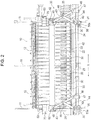
- FIGS. 2 and 3 are a front view and a perspective view of the bobbin replacement apparatus.
- a pot spinning machine will be described as an example of the spinning machine.
- a pot spinning machine 10 includes a plurality of fixed covers 12 that are disposed on opposite sides of a frame 11. It is effective to reduce the height of the frame 11 to reduce the height of the pot spinning machine 10.
- the fixed covers 12 are disposed along a spinning machine longitudinal direction X.
- the fixed cover 12 has a cylindrical shape.
- a pot (not shown) is disposed in the fixed cover 12.
- the pot spinning machine 10 is provided with a plurality of spindles on opposite sides of the frame 11.
- a spindle represents a unit of spinning.
- the fixed cover 12 and the pot are provided for each spindle.
- Each spindle is provided with a draft device, a sliver suction pipe, a yarn introduction pipe and the like (none of which are shown), in addition to the fixed cover 12 and the pot.
- a yarn stretched by the draft device is supplied to the yarn introduction pipe through the sliver suction pipe, which is introduced into the pot through the introduction pipe.
- the yarn is discharged from the bottom end of the introduction pipe in the pot, twisted by the rotation of the pot and laid on the inner wall of the pot.
- the position of the yarn introduction pipe is gradually moved downward while the yarn introduction pipe is repeatedly reciprocated in the vertical direction at predetermined intervals. Accordingly, a cake is formed on the inner wall of the pot.
- a bobbin is inserted into the pot and a yarn forming the cake is unwounded and wounded on the bobbin.
- a full bobbin having a predetermined amount of yarn wound on by winding of the yarn is removed from the pot.
- a bobbin replacement apparatus 20 is configured to replace the full bobbin with an empty bobbin to the pot spinning machine 10 operating in this manner.
- the bobbin replacement apparatuses 20 are disposed in pair on the opposite sides of the frame 11 corresponding to the plurality of spindles.
- the bobbin replacement apparatus 20 forms a simultaneous bobbin replacement apparatus that simultaneously replaces bobbins with respect to the plurality of spindles of the pot spinning machine 10.
- the bobbin replacement apparatus 20 includes a bobbin transport member 21 that transports the bobbin, a bobbin support member 22 that supports the bobbin, a bobbin holder 23 that holds the bobbin, a doffing bar 24 that supports the bobbin holder 23, a pantograph mechanism 25 serving as a lifting mechanism, a tilting mechanism 26 that tilts the entire pantograph mechanism 25, and a support mechanism 27 that supports the bobbin holder 23 via the doffing bar 24.
- the bobbin transport member 21 is configured to transport bobbins for carrying in empty bobbins to and carrying out full bobbins from the pot spinning machine 10 provided with the plurality of spindles. As shown in FIG. 4 , the bobbin transport member 21 includes a peg tray 31 and transports a bobbin 30 using the peg tray 31.
- the peg tray 31 has integrally therewith a peg 31a having a pointed shape.
- the peg tray 31 and the peg 31a have a circular shape in plan view.
- the bobbin 30 is configured to be inserted into or removed from the peg 31a of the peg tray 31.
- the peg tray 31 supports the bobbin 30 with the second bobbin support axis J2 that is disposed coaxially with the axis of the peg 31a at the center.
- the central axis of the bobbin 30 supported by the peg tray 31 is disposed coaxially with the second bobbin support axis J2.
- the second bobbin support axis J2 is an imaginary axis that extends in parallel with the vertical axis J5, which is an imaginary axis extending in the direction of the gravity. Accordingly, in the bobbin transport member 21, the bobbin 30 is supported by the peg tray 31 with the bobbin 30 arranged standing in the vertical direction.
- a plurality of peg trays 31 is disposed in the peg tray passage formed by a guide member 32.
- the guide member 32 forms a rail extending long in the spinning machine longitudinal direction X.
- the peg trays 31 are disposed at constant pitches along the spinning machine longitudinal direction X.
- the pitch between any two adjacent peg trays 31 is set at the same pitch between any two pots disposed along the spinning machine longitudinal direction X.
- the bobbin transport member 21 transports the bobbin 30 mounted on each peg tray 31 together with the peg tray 31.
- the peg trays 31 are disposed abutting to each other along the spinning machine longitudinal direction X.
- An intermediate peg 33 is disposed on a border between any two adjacently disposed peg trays 29 31 in the spinning machine longitudinal direction X.
- the intermediate peg 33 is provided for temporarily keeping an empty bobbin when the bobbin replacement apparatus 20 replaces bobbins.
- the dimension of the half pitch Pb between any two adjacently disposed intermediate pegs 33 in the spinning machine longitudinal direction X are set a half of the dimension of the pitch Pa between any two adjacently disposed pegs 31a in the spinning machine longitudinal direction X.
- the intermediate peg 33 is disposed at an intermediate position between two adjacently disposed pegs 31a in the spinning machine longitudinal direction X.
- the bobbin support member 22 supports the bobbin 30 that is used for rewinding of the yarn when spinning a yarn in the pot spinning machine 10. Additionally, the bobbin support member 22 supports the full bobbin that is disposed before replacing the bobbins and the empty bobbin that is disposed after replacing bobbins at different timings when the bobbin replacement operation is performed by the bobbin replacement apparatus 20. Thus, the bobbin support member 22 belongs to the pot spinning machine 10 and also to the bobbin replacement apparatus 20.
- the bobbin support member 22 supports the bobbin 30 with one to one relation to the pot provided for each spindle.
- the bobbin support member 22 includes a bobbin rail 36 and supports the bobbin 30 with the bobbin 30 disposed vertically standing on the bobbin rail 36.
- the bobbin rail 36 has a support pin 37.
- the support pin 37 has a circular shape in plan view.
- the support pin 37 is disposed standing vertically from the upper surface of the bobbin rail 36.
- the bobbin 30 is insertable and removable with respect to the support pin 37.
- the bobbin rail 36 supports the bobbin 30 with the first bobbin support axis J1 extending in the axis of the support pin 37 positioned at the center of the bobbin 30.
- the central axis of the bobbin 30 supported by the bobbin rail 36 is disposed coaxially with the first bobbin support axis J1.
- the bobbin 30 is supported in the bobbin support member 22 by the bobbin rail 36 with the bobbin 30 disposed standing vertically.
- the first bobbin support axis J1 is an imaginary axis extending in parallel with the vertical axis J5.
- the second bobbin support axis J2 and the first bobbin support axis J1 extend in parallel with each other.
- the second bobbin support axis J2 and the first bobbin support axis J1 are set at their respective positions that are shifted in the horizontal direction to each other.
- the second bobbin support axis J2 and the first bobbin support axis J1 are set at positions shifted from each other in the spinning machine short direction Y that extends perpendicularly to the spinning machine longitudinal direction X.
- the second bobbin support axis J2 is positioned farther from the frame 11 than the first bobbin support axis J1 is in the spinning machine short direction Y.
- the bobbin support member 22 is movable upward and downward by a lifter device 38.
- the lifter device 38 moves the bobbin support member 22 upward from its initial position for winding a yarn on the bobbin 30 in the pot.
- the lifter device 38 moves the bobbin support member 22 downward to the initial position for removing the bobbin 30 on which a yarn has been wound in the pot.
- the bottom portion of the bobbin 30 supported by the bobbin support member 22 is arranged at a position lower than the upper portion of the bobbin 30 supported by the bobbin transport member 21.
- the bobbin 30 supported by the bobbin support member 22 and the bobbin 30 supported by the bobbin transport member 21 shares part of a space in the height direction of the frame 11.
- the bobbins 30 supported with the first and second bobbin support axes J1, J2 as their respective centers do not interfere with each other.
- the first and second bobbin support axes J1, J2 are disposed coaxially
- the dimension of the frame 11 in height may be reduced, as compared with the case where the first and second bobbin support axes J1, J2 are disposed coaxially.
- the bobbin holder 23 is configured to holds the bobbin 30 while replacing the bobbins.
- the bobbin holder 23 has a bobbin insertion hole (not shown) into which the top end of the bobbin 30 is inserted, and holds the bobbin 30 with the holder axis J3 ( FIG. 1 ) extending through the bobbin insertion hole disposed at the center of the bobbin 30.
- the holder axis J3 is an imaginary axis, which is positioned coaxially with the central axis of the bobbin 30 when the bobbin 30 is held by the bobbin holder 23.
- a bobbin holder disclosed in Japanese Patent Application Publication H09-087931 may be used for the bobbin holder 23.
- the bobbin holder disclosed in the above-cited Publication includes a fixed holder member, a movable holder member, a diaphragm, and an urging member.
- the movable holder member is moved from the opened portion to the holding position by applying a fluid pressure to the movable holder member through the diaphragm, so that a bobbin is held between the fixed holder member and the movable holder member.
- the movable holder member is moved to the release position by urging member by releasing the fluid pressure to the diaphragm, thus the holding of the bobbin is released.
- the doffing bar 24 extends long in the spinning machine longitudinal direction X and is disposed extending.
- the doffing bar 24 moves upward and downward with its horizontal posture maintained by driving of the pantograph mechanism 25.
- the plurality of bobbin holders 23, which are provided in one to one relation to the pot of each spindle, are along the longitudinal direction of the doffing bar 24.
- Each bobbin holder 23 is mounted to the doffing bar 24 with a screw and the like.
- the plurality of the bobbin holders 23 are supported by the doffing bar 24.
- the pantograph mechanism 25 is configured to move the doffing bar 24 upward and downward in the direction of the lift axis J4 ( FIGS. 1 and 2 ).
- the lift axis J4 is an imaginary axis.
- the pantograph mechanism 25 is rotatably supported with the drive shaft 42 disposed at the center of the pantograph mechanism 25.
- the drive shaft 42 is disposed extending horizontally along the spinning machine longitudinal direction X.
- the drive shaft 42 is reciprocally movable in the spinning machine longitudinal direction X with the operation of a power cylinder (not shown).
- the pantograph mechanism 25 includes a first link 43 and a second link 44.
- One end of the first link 43 is connected to a fixed member 62 by a connection pin 45.
- the doffing bar 24 is mounted to the fixed member 62.
- a plurality of first links 43 and a plurality of second links 44 are provided at predetermined intervals in the spinning machine longitudinal direction X.
- the doffing bar 24 is disposed horizontally between the upper end portions of the two first links 43 disposed adjacently to each other in the spinning machine longitudinal direction X.
- the other end of the first link 43 is connected to a moving bracket 47 by a connection pin 46.
- the connection pins 45, 46 form link joints of the pantograph mechanism 25, respectively.
- the link joint formed by the connection pin 45 and the link joint formed by the connection pin 46 are disposed on the lift axis J4.
- the moving bracket 47 is fixed to the drive shaft 42 so as to move integrally with the drive shaft 42 in the spinning machine longitudinal direction X.
- the second link 44 has a length a half of the first link 43.
- the one end of the second link 44 is connected to an intermediate portion of the first link 43 in the length direction thereof by a connection pin 48.
- the other end of the second link 44 is connected to a support bracket 50 by a connection pin 49.
- the connection pins 48, 49 form link joints of the pantograph mechanism 25, respectively.
- a fixed bracket 51 restricts the movement of the support bracket 50 in the axial direction of the drive shaft 42.
- the support bracket 50 is mounted on the drive shaft 42 for rotation therewith while permitting the movement of the drive shaft 42 in the spinning machine longitudinal direction X.
- the reciprocating movement of the drive shaft 42 in the spinning machine longitudinal direction X driven by the power cylinder (not shown) causes the doffing bar 24 to move upward and downward with the movement of the first link 43 and the second link 44.
- the bobbin holder 23 moves upward and downward with the doffing bar 24 with the upward and downward movement of the doffing bar 24.
- the tilting mechanism 26 is configured to tilt the entire pantograph mechanism 25 relative to the vertical axis J5.
- the lift axis J4 of the pantograph mechanism 25 tilts relative to the second bobbin support axis J2 by tilting the pantograph mechanism 25 by the tilting mechanism 26.
- the tilting mechanism 26 includes the above-described drive shaft 42 and tilts the entire pantograph mechanism 25 by rotating the pantograph mechanism 25 about the drive shaft 42.
- the drive shaft 42 serves as axis of rotation when the tilting mechanism 26 tilts the pantograph mechanism 25.
- a tilting mechanism disclosed in the above-cited Japanese Patent Application Publication No. H07-126930 may be used.
- a lever 50a formed integrally with the support bracket 50 is rotated about the drive shaft 42 by an air cylinder (not shown), and thereby the entire pantograph mechanism 25 rotates with the support bracket 50 about the drive shaft 42.
- the tilting mechanism 26 is not limited to the configuration disclosed in the above-cited Publication as long as it can rotates the entire pantograph mechanism 25 about the drive shaft 42.
- the support mechanism 27 is disposed between the pantograph mechanism 25 and the doffing bar 24, and supports the bobbin holder 23 through the doffing bar 24.
- the support mechanism 27 includes a position changing mechanism 61 configured to change the position of the bobbin holder 23 so that at least two angles is set by an angle between the holder axis J3 of the bobbin holder 23 and the lift axis J4 of the pantograph mechanism 25.
- the position changing mechanism 61 includes a hinge 66. The position of the bobbin holder 23 is determined by the angle between the holder axis J3 and the lift axis J4, and the position of the bobbin holder 23 is changed by a change of such angle.
- FIG. 9 is a perspective view, showing the mounting of the pantograph mechanism, a doffing bar and a support mechanism, as viewed from the front side
- FIG. 10 is a perspective view, showing the mounting of the pantograph mechanism, the doffing bar and the support mechanism, as viewed from the frame side.
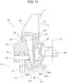
- FIG. 11 is a partial cross-sectional view, showing the support mechanism when the pantograph mechanism is disposed standing vertically
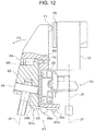
- FIG. 12 is a partial cross-sectional view, showing a state of the support mechanism when the pantograph mechanism is tilted.
- the support mechanism 27 includes the fixed member 62 and the movable member 63.
- the fixed member 62 is a member that is fixed to the pantograph mechanism 25.
- a recess 64 is formed in the fixed member 62.
- the upper end portion of the first link 43 is inserted into the recess 64.
- the upper end portion of the first link 43 is connected to the fixed member 62 by the connection pin 45 with the upper end portion of the first link 43 inserted into the recess 64.
- a protruded portion 65 is formed in the upper end portion of the fixed member 62.
- the protruded portion 65 is formed integrally with the fixed member 62.
- the movable member 63 is connected to the fixed member 62 via the hinge 66.
- the hinge 66 includes a pin 66a, and a pair of leaf members 66b, 66c that are rotatable about the pin 66a.
- the pin 66a is disposed in parallel to the drive shaft 42.
- One of the leaf members 66b, 66c (one leaf member 66b) is fixed to the lower surface of the fixed member 62 by a screw 67a and the other of the leaf members 66b, 66c (the other leaf member 66c) is fixed to the lower surface of the movable member 63 by a screw 67b.
- the movable member 63 is rotatable about the pin 66a of the hinge 66 and supported by the fixed member 62.
- the doffing bar 24 is fixed to the movable member 63 by a screw and the like.
- a hook portion 68 is formed in the movable member 63.
- the hook portion 68 is formed so as to correspond to the protruded portion 65 of the fixed member 62.
- An adjustment screw 69 is fixed to the movable member 63 at a position facing the hook portion 68.
- the adjustment screw 69 is fastened to a screw hole 70 formed in the movable member 63.
- the adjustment screw 69 serves as the adjustment member that adjusts the position change amount of the bobbin holder 23 by the position changing mechanism 61.
- the adjustment screw 69 is provided by the hex screw. A predetermined amount of the tip of the adjustment screw 69 projects from the surface of the movable member 63.
- the projected amount of the adjustment screw 69 is adjustable by rotating the adjustment screw 69.
- the tip of the adjustment screw 69 is a part that is set in contact with the protruded portion 65 of the fixed member 62 when changing the position of the bobbin holder 23 by the position changing mechanism 61.
- the position change amount of the bobbin holder 23 may be changed by adjusting the projection amount of the adjustment screw 69.
- the adjustment of the position change amount of the bobbin holder 23 using the adjustment screw 69 is advantageous when adjusting the position of the bobbin holder 23 by the position changing mechanism 61 so as to position the holder axis J3 relative to the first bobbin support axis J1 and dispose the holder axis J3 and the first bobbin support axis J1 coaxially.
- a contact portion 71 is formed in the movable member 63.
- the contact portion 71 may be formed integrally with or separately from the movable member 63.
- the contact portion 71 is fixed to the upper portion of the movable member 63 by a screw or the like.
- the contact portion 71 has a half-moon shape in side view and projects towards the fixed cover 12.
- a stopper 75 is fixed to the frame 11.
- the stopper 75 forms a part of the bobbin replacement apparatus 20 and is disposed so as to surround one of the fixed covers 12.
- the stopper 75 is fixed to the frame 11 by a screw or the like.
- the stopper 75 is arranged at a position facing the contact portion 71 of the movable member 63 in the spinning machine short direction Y. Accordingly, when changing the position of the bobbin holder 23 with the position changing mechanism 61, the contact portion 71 of the movable member 63 is configured to be in contact with the stopper 75 by tilting the entire pantograph mechanism 25 by the tilting mechanism 26.
- the movable member 63 is mounted to the bobbin holder 23 via the doffing bar 24.
- the doffing bar 24 and the bobbin holder 23 are disposed shifted in one direction relative to the pin 66a of the hinge 66, so that the gravitational center of the whole mechanism including the movable member 63, the doffing bar 24, and the bobbin holder 23 is shifted in such one direction.
- the rotational force F1 in the clockwise direction in FIG. 11 is applied to the movable member 63 by the weight of the bobbin holder 23 and the doffing bar 24, which causes the hook portion 68 of the movable member 63 to be in contact with the protruded portion 65 of the fixed member 62.
- the support mechanism 27 having the above-described configuration maintains the angle between the holder axis J3 and the lift axis J4 at a first angle that is the same as the angle ⁇ 1 when the lift axis J4 of the pantograph mechanism 25 is arranged in parallel with the second bobbin support axis J2.
- the angle ⁇ 1 is the angle between the lift axis J4 and the vertical axis J5, and equal to the angle between the lift axis J4 and the second bobbin support axis J2, since the second bobbin support axis J2 extends vertically.
- the angle ⁇ 1 becomes 0° when the lift axis J4 of the pantograph mechanism 25 is arranged in parallel to the second bobbin support axis J2. As shown in FIG. 8 , when the lift axis J4 of the pantograph mechanism 25 is tilted relative to the second bobbin support axis J2 by the tilting mechanism 26, the support mechanism 27 maintains the angle between the holder axis J3 and the lift axis J4 at the second angle, which is the same angle with the angle ⁇ 2.
- the angle ⁇ 2 is the angle between the lift axis J4 and the vertical axis J5, and is equal to the angle between the lift axis J4 and the first bobbin support axis J1, since the first bobbin support axis J1 extends vertically.
- the angle ⁇ 2 becomes greater than the angle ⁇ 1.
- the movable member 63 When the lift axis J4 of the pantograph mechanism 25 and the second bobbin support axis J2 are arranged in parallel, the movable member 63 is subjected to the rotational force F1 in the clockwise direction in FIG. 11 due to the weight of the bobbin holder 23 and the doffing bar 24.
- the hook portion 68 of the movable member 63 is placed in contact with the protruded portion 65 of the fixed member 62 by this rotational force F1. This permits maintaining the angle between the holder axis J3 and the lift axis J4 at the first angle that is the same angle with the angle ⁇ 1 ( FIG. 7 ).
- the holder axis J3 is arranged in parallel with the second bobbin support axis J2.
- the first angle is maintained at 0°. While the first angle is maintained, the holder axis J3 and the second bobbin support axis J2 are arranged coaxially, which means that two axes are disposed on the same axis. The holder axis J3 and the second bobbin support axis J2 are coaxially arranged so that the bobbin holder 23 can hold the bobbin 30 supported with the second bobbin support axis J2 at the center of the bobbin 30 in the bobbin transport member 21.
- the holder axis J3 is arranged in parallel to the first bobbin support axis J1 and the second bobbin support axis J2 even when the lift axis J4 tilts relative to the second bobbin support axis J2.
- the second angle is maintained at an angle greater than 0°.
- the holder axis J3 and the first bobbin support axis J1 are arranged coaxially.
- the holder axis J3 and the first bobbin support axis J1 are arranged coaxially so that the bobbin holder 23 can hold the bobbin 30 supported with the first bobbin support axis J1 at the center of the bobbin 30 in the bobbin support member 22.
- the bobbin replacement operation using the bobbin replacement apparatus 20 having the above-described configuration.
- the bobbin 30 supported by the bobbin support member 22 is inserted into the pot where a yarn is wound on the bobbin 30 by moving the bobbin support member 22 upward by the lifter device 38.
- the bobbin replacement apparatus 20 starts the following operations before the winding of yarn on the bobbin 30 in the pot is completed.
- Each empty bobbin 30 is transported to the positions corresponding to each spindle by the bobbin transport member 21.
- Each empty bobbin 30 is mounted on the peg 31a of the peg tray 31 when being transported.
- the second bobbin support axis J2 of the bobbin transport member 21 is disposed coaxially with the holder axis J3 of the bobbin holder 23.
- the empty bobbin 30 is disposed right blow the bobbin holder 23.
- pantograph mechanism 25 moves the doffing bar 24 downward.
- the lift axis J4 of the pantograph mechanism 25 is disposed in parallel to the second bobbin support axis J2.
- the doffing bar 24 moves downward straight along the second bobbin support axis J2 together with the bobbin holder 23.
- the bobbin holder 23 holds the empty bobbin 30 transported by the bobbin transport member 21 in the above-described manner.
- the pantograph mechanism 25 moves the doffing bar 24 upward.
- the bobbin holder 23 moves upward with the doffing bar 24 while holding the empty bobbin 30.
- the empty bobbin 30 is pulled out from the peg tray 31 of the bobbin transport member 21.
- the bobbin transport member 21 moves the positions of the peg trays 31 by the half pitch Pb ( FIG. 5 ) in one of the directions along the spinning machine longitudinal direction X.
- the intermediate peg 33 is arranged right below the bobbin holder 23.
- the bobbin transport member 21 moves the positions of the peg tray 31 by the half pitch Pb ( FIG. 5 ) in the other direction along the spinning machine longitudinal direction X. Accordingly, the peg 31a of the peg tray 31 is arranged right below the bobbin holder 23. If the winding of yarn on the bobbin 30 is not completed in the pot, the bobbin replacement apparatus 20 stands by until the winding of yarn on the bobbin 30 is completed.
- the lifter device 38 moves the bobbin support member 22 downward. As a result, the full bobbin 30 having completed the winding of yarn is removed from the pot.
- the entire pantograph mechanism 25 tilts relative to the second bobbin support axis J2 by the first tilting operation of the tilting mechanism 26. Tilting the pantograph mechanism 25, the contact portion 71 of the movable member 63 hits the stopper 75, which rotates the movable member 63 about the pin 66a of the hinge 66 by the reaction force generated by hitting the stopper 75 with the contact portion 71 of the movable member 63. The rotational movement of the movable member 63 causes the hook portion 68 to move away from the protruded portion 65, and the tip of the adjustment screw 69 hits the protruded portion 65.
- the angle between the holder axis J3 and the lift axis J4 is maintained at the second angle.
- the holder axis J3 of the bobbin holder 23 is disposed coaxially with the first bobbin support axis J1 of the bobbin support member 22.
- the lifter device 38 moves the bobbin support member 22 upward, and the bobbin holder 23 holds the full bobbin 30.
- the tilting of the pantograph mechanism 25 relative to the second bobbin support axis J2 is released by the second tilting movement of the tilting mechanism 26.
- the lift axis J4 of the pantograph mechanism 25 and the second bobbin support axis J2 are arranged in parallel.
- the contact portion 71 of the movable member 63 moves away from the stopper 75.
- the movable member 63 rotates about pin 66a of the hinge 66.
- the angle between the holder axis J3 and the lift axis J4 is maintained at the first angle.
- the holder axis J3 of the bobbin holder 23 is arranged coaxially with the second bobbin support axis J2 of the bobbin transport member 21.
- the pantograph mechanism 25 moves the doffing bar 24 downward, and the holding of the bobbin 30 by the bobbin holder 23 is released. Accordingly, the full bobbin 30 is mounted on the peg tray 31 of the bobbin transport member 21.
- the bobbin transport member 21 moves the position of the peg tray 31 by the half pitch Pb in the one of the directions along the spinning machine longitudinal direction X, which positions the intermediate pegs 33 right below the bobbin holder 23.
- the empty bobbin 30 is mounted on the intermediate pegs 33.
- the bobbin holder 23 holds the empty bobbin 30 mounted on the intermediate peg 33.
- the pantograph mechanism 25 moves the doffing bar 24 upward, the entire pantograph mechanism 25 tilts relative to the second bobbin support axis J2 by the first tilting movement of the tilting mechanism 26. This maintains the angle between the holder axis J3 and the lift axis J4 at the second angle.
- the holder axis J3 of the bobbin holder 23 is arranged coaxially with the first bobbin support axis J1 of the bobbin support member 22.
- the lifter device 38 moves the bobbin support member 22 upward, the bobbin holder 23 releases the holding of the bobbins 30.
- the empty bobbin 30 is mounted on the support pin 37 of the bobbin support member 22.
- the tilting of the pantograph mechanism 25 relative to the second bobbin support axis J2 is released by the second tilting movement of the tilting mechanism 26.
- the holder axis J3 of the bobbin holder 23 is disposed coaxially with the second bobbin support axis J2 of the bobbin transport member 21.
- the bobbin 30 supported by the bobbin support member 22 is replaced from the full bobbin to the empty bobbin.
- a controller (not shown), which collectively controls the operations of the pot spinning machine 10 and the bobbin replacement apparatus 20, by controlling the operation of the bobbin transport member 21, the bobbin support member 22, the bobbin holder 23 the pantograph mechanism 25, and the tilting mechanism 26.
- the empty bobbin 30 to be transported by the bobbin transport member 21 may be transported with such empty bobbin 30 mounted on the intermediate peg 33.
- Steps 2 through 7 are omitted.
- the peg 31a of the peg tray 31 and the intermediate pegs 33 are mutually replaceable.
- the second bobbin support axis J2 of the bobbin transport member 21 and the first bobbin support axis J1 of the bobbin support member 22 are set at positions shifted from each other in the horizontal direction.
- the support mechanism 27 maintains the angle between the holder axis J3 and the lift axis J4 at the first angle, and the holder axis J3 and the second bobbin support axis J2 are coaxially disposed.
- the angle between the holder axis J3 and the lift axis J4 is maintained at the second angle that is greater than the first angle, and the holder axis J3 and the first bobbin support axis J1 are arranged coaxially. Accordingly, the bobbin 30 supported by the bobbin transport member 21 and the bobbin 30 supported by the bobbin support member 22 are held by their associated bobbin holders 23, even the positions of the first bobbin support axis J1 and the second bobbin support axis J2 are shifted in the horizontal direction during the bobbin replacement by the bobbin replacement apparatus 20.
- the height of the frame 11 of the pot spinning machine 10 may be reduced.
- the frame 11 of the pot spinning machine 10 and hence the height of the pot spinning machine 10 may be reduced without tilting the bobbin support axes J1, J2 relative to the vertical axis J5.
- the support mechanism 27 includes the fixed member 62 that is fixed to the pantograph mechanism 25 and the movable member 63 that is mounted to the fixed member 62, and has the configuration in which the bobbin holder 23 is mounted to the movable member 63 via the doffing bar 24. This enables to change the position of the bobbin holder 23 by using the movement of the movable member 63 relative to the fixed member 62 with a simple structure.
- the contact portion 71 is formed in the movable member 63 and the stopper 75 is formed in the frame 11 so as to correspond to the contact portion 71.
- the angle between the holder axis J3 and the lift axis J4 is maintained at the second angle by the contact portion 71 in contact with the stopper 75.
- the angle between the holder axis J3 and the lift axis J4 may be maintained at the second angle by changing the position of the bobbin holder 23 utilizing the movement of the tilting mechanism 26 without providing an additional driving system.
- the bobbin replacement apparatus 20 is configured to maintain the angle between the holder axis J3 and the lift axis J4 at the first angle by the weight of the bobbin holder 23 and the doffing bar 24.
- the support mechanism 27 fewer parts are needed for the support mechanism 27.
- the bobbin replacement apparatus 20 includes the hook portion 68 that adjusts the position change amount of the bobbin holder 23 by the position changing mechanism 61.
- the angle between the holder axis J3 and the lift axis J4 may be set at a desired angle precisely when the tilting mechanism 26 tilts the pantograph mechanism 25.
- the present disclosure is not limited to this configuration.
- the bobbin replacement apparatus 20 includes a spring member 77 as an elastic member at a position where the fixed member 62 faces the movable member 63, the first angle may be maintained by an elastic force (spring force) of the spring member 77.
- the elastic member is not limited to the spring member, but may be a rubber member having the great flexibility.
- the bobbin replacement apparatus 20 may include a magnet 78a in the protruded portion 65 of the fixed member 62 and a magnet 78b in the hook portion 68 of the movable member 63 so as to maintain the first angle by the magnetic force between the two magnets 78a, 78b.
- One of the two magnets 78a, 78b may be replaced with a metal piece to be attracted to the magnet.
- the vibration of the doffing bar 24 and the bobbin holder 23 may be suppressed during the lift movement caused by the pantograph mechanism 25 and the tilting movement caused by the tilting mechanism 26
- the position changing mechanism 61 need not necessarily be formed by using the hinge 66 in the above-described embodiment, but may be provided by any members that can changes the position of the bobbin holder 23 so as to change the angle between the holder axis J3 and the lift axis J4.
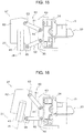
- the position changing mechanism 61 may be provided by a link mechanism 80 shown in FIG. 15 .
- the link mechanism 80 includes an upper link 81 and a lower link 82. One end of the upper link 81 is connected to the fixed member 62 by a pin 83 and the other end of the upper link 81 is connected to the movable member 63 by a pin 84.
- the holder axis J3 of the bobbin holder 23 is arranged extending vertically when the lift axis J4 of the pantograph mechanism 25 is arranged extending vertically.
- the holder axis J3 of the bobbin holder 23 extends vertically due to the change of the position of the bobbin holder 23 with the movement of the link mechanism 80.
- pantograph mechanism 25 is used as an example of the lifting mechanism in the present embodiment, any mechanism that can move the doffing bar 24 upward and downward may be used as the lifting mechanism.
- the present disclosure is not limited to the pot spinning machine, but is applicable to a ring spinning machine.
- a spindle (not shown) is provided in the bobbin support member, instead of the bobbin rail 36. Since the pot spinning machines need to secure a space for disposing cylindrical members such as a pot and a space for the operations to insert the bobbins into the pot and removed therefrom, the dimension in height of the pot spinning machines tends to becomes large, as compared with the ring spinning machines. Therefore, it offers more significant effect that restricts the height of the spinning machine when the present disclosure is applied to the pot spinning machine.
- a bobbin replacement apparatus (20) of a spinning machine includes a first bobbin support axis (J1) extending in parallel to a vertical axis (J5), a second bobbin support axis (J2) that is disposed at a position shifted from the first bobbin support axis (J1) in a horizontal direction, a holder axis (J3),and a lift axis (J4).
- a first bobbin support axis (J1) extending in parallel to a vertical axis (J5)
- a second bobbin support axis (J2) that is disposed at a position shifted from the first bobbin support axis (J1) in a horizontal direction
- a holder axis (J3) and a lift axis (J4).
- the angle between the holder axis (J3) and the lift axis (J4) is maintained at a second angle, and the holder axis (J3) and the second bobbin support axis (J2) are disposed coaxially.
Landscapes
- Engineering & Computer Science (AREA)
- Mechanical Engineering (AREA)
- Textile Engineering (AREA)
- Spinning Or Twisting Of Yarns (AREA)
Abstract
Description
- The present disclosure relates to a bobbin replacement apparatus of a spinning machine.
- Some spinning machines includes a simultaneous bobbin replacement apparatus that performs the operation replacing bobbin mounted to a plurality of spindles in all the spindles stations simultaneously, i.e., replacing full bobbins with empty bobbins in all the spindles at the same time. Japanese Patent Application Publication
H07-126930 - The above-cited Publication discloses a simultaneous bobbin replacement apparatus that includes a pantograph mechanism that moves the doffing bar having bobbin holder upward and downward, and a transport mechanism that transports the entire pantograph mechanism between a position close to the spinning machine and a position away from the spinning machine by rotating the pantograph mechanism about the drive shaft.
- The simultaneous bobbin replacement apparatus of the above-cited Publication includes a bobbin transport member that transports bobbins using a plurality of peg trays and is disposed below a spindle rail to which a plurality of spindles are provided. The replacement of the bobbins mounted to the spindles, the full bobbin with the empty bobbin, is accomplished by the upward and downward movement of the doffing bar by the pantograph mechanism and the rotational movement of the pantograph mechanism by the moving mechanism.
- Specifically, the bobbin holder holds the empty bobbin mounted on the peg tray with the upward and downward movement of the doffing bar caused by the pantograph mechanism. The bobbin holder moves upward and downward in accordance with the upward and downward movement of the doffing bar, and holds the empty bobbin using this movement.
- Then, the empty bobbin held by the bobbin holder is mounted on the intermediate peg with the upward and downward movement of the doffing bar caused by the pantograph mechanism and the rotational movement of the pantograph mechanism caused by the pantograph mechanism.
- Then, the bobbin holder holds a full bobbin mounted on the spindle with the upward and downward movement of the doffing bar caused by the pantograph mechanism, and then such full bobbin held by the bobbin holder is mounted on the peg tray by the upward and downward movement of the doffing bar caused by the pantograph mechanism and the rotational movement of the pantograph mechanism caused by the moving mechanism.
- Subsequently, the bobbin holder holds the empty bobbin mounted on the intermediate peg with the upward and downward movement of the doffing bar by the pantograph mechanism and the rotational movement of the pantograph mechanism by the moving mechanism, such empty bobbin is mounted on the spindle by the upward and downward movement of the doffing bar by the pantograph mechanism and the rotational movement of the pantograph mechanism by the moving mechanism. Accordingly, the bobbins mounted on the spindle are replaced from the full bobbin to the empty bobbins.
- However, the simultaneous bobbin replacement apparatus of the above-cited Publication increases the height of the spinning machine due to the following reasons.
- When mounting the bobbin on the peg trays of the bobbin transport member and removing therefrom, the bobbin transport member may be moved upward and downward the elevation movement of the doffing bar by the pantograph mechanism, instead of moving the bobbin holder upward and downward with the upward and downward movement of the doffing bar by the pantograph mechanism. However, it requires a new driving system to move the bobbin transport member upward and downward in order to move the bobbin transport member upward and downward, which makes the configuration of the simultaneous bobbin replacement apparatus complex and large. Therefore, it is preferable that the mounting the bobbin on the peg trays and removing therefrom are accomplished by using the upward and downward movement of the doffing bar by the pantograph mechanism.
- However, in order to accomplish the mounting the bobbin on the peg trays and removing therefrom by the upward and downward movement of the doffing bar by the pantograph mechanism, it requires to arrange the spindle and the peg tray with a large space secured therebetween in the vertical direction and to dispose the bobbin support axis of the spindle and the bobbin support axis of the peg tray coaxially. In addition, the bobbin holder needs to be moved upward and downward when mounting the bobbin on spindle and removing therefrom and when mounting the bobbin on the peg trays of the bobbin transport member and removing therefrom. Therefore, spaces need to be secured above the spindle and above the peg tray for the operation to mount and remove the bobbin, in addition to the dimension of the bobbin in the longitudinal direction thereof. As a result, the height of the spinning machine is increased.
- The above-mentioned space for the operation to mount and remove the bobbin is for the upward and downward movement of the bobbin holder with the upward and downward movement of the doffing bar by the pantograph mechanism. The bobbin support axis is an imaginary axis that is set at parts such as a spindle and a peg tray on which the bobbin is mounted insertably and removably. The spindle and the peg tray support the bobbin with the bobbin support axis at the center of the bobbin. In the simultaneous bobbin replacement apparatus of the above-cited Publication, the bobbin support axis of the spindle and the bobbin support axis of the peg tray are disposed in parallel with the vertical axis, respectively. In the present specification, the vertical axis corresponds to the axis extending in parallel to the direction of the gravity.
- As a means for reducing the height of the spinning machine, it may be considered that one of or both of the bobbin support axis of the spindle and the bobbin support axis of the peg tray are inclined relative to the vertical axis. If the bobbin support axis of the spindle is tilted, however, the gravitational force acts on the spindle and the bobbin in the tilted direction when the bobbin is being rotated by the spindle, which makes the rotation of the spindle and the bobbin unstable. Additionally, if the bobbin support axis of the peg tray is tilted, the bobbin may be come off from the peg tray during the transport of the bobbin by the bobbin transport member. Further, the configuration of a winder device that receives, from the bobbin transport member, the full bobbin having completed the winding of yarn in the spinning machine may be greatly altered so as to correspond to the tilting of the bobbin support axis of the peg tray.
- The present disclosure is directed to providing a bobbin replacement apparatus of a spinning machine that permits reducing the height of the spinning machine without tilting a bobbin support axis relative to a vertical axis.
- In accordance with an aspect of the present disclosure, there is provided a bobbin replacement apparatus of a spinning machine includes a bobbin support member that supports a bobbin with a first bobbin support axis extending in parallel to a vertical axis arranged at a center of the bobbin, a bobbin transport member that supports the bobbin with a second bobbin support axis that is disposed at a position shifted from the first bobbin support axis in a horizontal direction arranged at the center of the bobbin, a bobbin holder that holds the bobbin with a holder axis arranged at the center of the bobbin, a doffing bar that supports the bobbin holder, a lifting mechanism that moves the doffing bar upward and downward in a direction parallel to a lift axis, and a tilting mechanism the entire lifting mechanism relative to the vertical axis. The bobbin replacement apparatus further includes a support mechanism supporting the bobbin holder via the doffing bar between the lifting mechanism and the doffing bar. The support mechanism includes a position changing mechanism that changes a position of the bobbin holder so that an angle between the holder axis and the lift axis is set at least two different angles, wherein the angle between the holder axis and the lift axis is maintained at a first angle when the lift axis and the second bobbin support axis are disposed in parallel, and the angle between the holder axis and the lift axis is maintained at a second angle that is greater the first angle when the lift axis of the lifting mechanism is tilted by the tilting mechanism. The holder axis and the second bobbin support axis are disposed coaxially when the support mechanism maintains the angle between the holder axis and the lift axis at the first angle, and the holder axis and the first bobbin support axis are disposed coaxially when the support mechanism maintains the angle between the holder axis and the lift axis at the second angle.
- Other aspects and advantages of the present disclosure will become apparent from the following description, taken in conjunction with the accompanying drawings, illustrating by way of example the principles of the present disclosure.
- The present disclosure together with objects and advantages thereof may best be understood by reference to the following description of the presently preferred embodiments together with the accompanying drawings in which:
-
FIG. 1 is a side view, showing an example of the configuration of a bobbin replacement apparatus of a spinning machine according to an embodiment of the present disclosure; -
FIG. 2 is a front view of the bobbin replacement apparatus of the spinning machine ofFIG. 1 ; -
FIG. 3 is a perspective view of the bobbin replacement apparatus of the spinning machine ofFIG. 1 ; -
FIG. 4 is a view, showing a configuration of a bobbin transport member; -
FIG. 5 is a view showing an arrangement of a peg tray and an intermediate peg in a spinning machine longitudinal direction; -
FIG. 6 is a view, showing a configuration of a bobbin support member; -
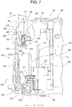
FIG. 7 is a side view, showing various members before a pantograph mechanism is tilted; -
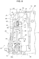
FIG. 8 is a side view, showing various members after the pantograph mechanism is tilted; -
FIG. 9 is a perspective view, showing the mounting of the pantograph mechanism, a doffing bar, and a support mechanism, as viewed from the front side; -
FIG. 10 is a perspective view, showing the mounting of the pantograph mechanism, the doffing bar, and the support mechanism, as viewed from the frame side; -
FIG. 11 is a partial cross-sectional view, showing the support mechanism when the pantograph mechanism is disposed standing vertically; -
FIG. 12 is a partial cross-sectional view, showing a state of the support mechanism when the pantograph mechanism is tilted; -
FIG. 13 is a side view, showing an example of the configuration of the support mechanism in which a spring member is provided; -
FIG. 14 is a side view, showing another example of the configuration of the support mechanism in which a magnet is provided; -
FIG. 15 is a side view, showing an example of a position changing mechanism; and -
FIG. 16 is a side view, showing another example of the position changing mechanism. - The following will describe an embodiment of the present disclosure with reference to the accompanying drawings.
-
FIG. 1 is a side view, showing an example of the configuration of a bobbin replacement apparatus of a spinning machine according to an embodiment of the present disclosure.FIGS. 2 and3 are a front view and a perspective view of the bobbin replacement apparatus. In the description of the present embodiment, a pot spinning machine will be described as an example of the spinning machine. - As shown in
FIG. 1 , apot spinning machine 10 includes a plurality of fixedcovers 12 that are disposed on opposite sides of aframe 11. It is effective to reduce the height of theframe 11 to reduce the height of thepot spinning machine 10. As shown inFIG. 2 , thefixed covers 12 are disposed along a spinning machine longitudinal direction X. Thefixed cover 12 has a cylindrical shape. A pot (not shown) is disposed in thefixed cover 12. Thepot spinning machine 10 is provided with a plurality of spindles on opposite sides of theframe 11. A spindle represents a unit of spinning. The fixedcover 12 and the pot are provided for each spindle. Each spindle is provided with a draft device, a sliver suction pipe, a yarn introduction pipe and the like (none of which are shown), in addition to the fixedcover 12 and the pot. - The following will briefly describe a basic operation of the
pot spinning machine 10. Firstly, in thepot spinning machine 10, a yarn stretched by the draft device is supplied to the yarn introduction pipe through the sliver suction pipe, which is introduced into the pot through the introduction pipe. The yarn is discharged from the bottom end of the introduction pipe in the pot, twisted by the rotation of the pot and laid on the inner wall of the pot. At this time, the position of the yarn introduction pipe is gradually moved downward while the yarn introduction pipe is repeatedly reciprocated in the vertical direction at predetermined intervals. Accordingly, a cake is formed on the inner wall of the pot. With the pot kept rotated, a bobbin is inserted into the pot and a yarn forming the cake is unwounded and wounded on the bobbin. Then, a full bobbin having a predetermined amount of yarn wound on by winding of the yarn is removed from the pot. - A
bobbin replacement apparatus 20 is configured to replace the full bobbin with an empty bobbin to thepot spinning machine 10 operating in this manner. Thebobbin replacement apparatuses 20 are disposed in pair on the opposite sides of theframe 11 corresponding to the plurality of spindles. Thebobbin replacement apparatus 20 forms a simultaneous bobbin replacement apparatus that simultaneously replaces bobbins with respect to the plurality of spindles of thepot spinning machine 10. - The
bobbin replacement apparatus 20 includes abobbin transport member 21 that transports the bobbin, abobbin support member 22 that supports the bobbin, abobbin holder 23 that holds the bobbin, a doffingbar 24 that supports thebobbin holder 23, apantograph mechanism 25 serving as a lifting mechanism, atilting mechanism 26 that tilts theentire pantograph mechanism 25, and asupport mechanism 27 that supports thebobbin holder 23 via the doffingbar 24. - The
bobbin transport member 21 is configured to transport bobbins for carrying in empty bobbins to and carrying out full bobbins from thepot spinning machine 10 provided with the plurality of spindles. As shown inFIG. 4 , thebobbin transport member 21 includes apeg tray 31 and transports abobbin 30 using thepeg tray 31. Thepeg tray 31 has integrally therewith apeg 31a having a pointed shape. Thepeg tray 31 and thepeg 31a have a circular shape in plan view. Thebobbin 30 is configured to be inserted into or removed from thepeg 31a of thepeg tray 31. Thepeg tray 31 supports thebobbin 30 with the second bobbin support axis J2 that is disposed coaxially with the axis of thepeg 31a at the center. Thus, the central axis of thebobbin 30 supported by thepeg tray 31 is disposed coaxially with the second bobbin support axis J2. The second bobbin support axis J2 is an imaginary axis that extends in parallel with the vertical axis J5, which is an imaginary axis extending in the direction of the gravity. Accordingly, in thebobbin transport member 21, thebobbin 30 is supported by thepeg tray 31 with thebobbin 30 arranged standing in the vertical direction. - A plurality of
peg trays 31 is disposed in the peg tray passage formed by aguide member 32. Theguide member 32 forms a rail extending long in the spinning machine longitudinal direction X. Thepeg trays 31 are disposed at constant pitches along the spinning machine longitudinal direction X. The pitch between any twoadjacent peg trays 31 is set at the same pitch between any two pots disposed along the spinning machine longitudinal direction X. - The
bobbin transport member 21 transports thebobbin 30 mounted on eachpeg tray 31 together with thepeg tray 31. As shown inFIG. 5 , thepeg trays 31 are disposed abutting to each other along the spinning machine longitudinal direction X. Anintermediate peg 33 is disposed on a border between any two adjacently disposed peg trays 29 31 in the spinning machine longitudinal direction X. Theintermediate peg 33 is provided for temporarily keeping an empty bobbin when thebobbin replacement apparatus 20 replaces bobbins. The dimension of the half pitch Pb between any two adjacently disposedintermediate pegs 33 in the spinning machine longitudinal direction X are set a half of the dimension of the pitch Pa between any two adjacently disposedpegs 31a in the spinning machine longitudinal direction X. In other words, theintermediate peg 33 is disposed at an intermediate position between two adjacently disposedpegs 31a in the spinning machine longitudinal direction X. - The
bobbin support member 22 supports thebobbin 30 that is used for rewinding of the yarn when spinning a yarn in thepot spinning machine 10. Additionally, thebobbin support member 22 supports the full bobbin that is disposed before replacing the bobbins and the empty bobbin that is disposed after replacing bobbins at different timings when the bobbin replacement operation is performed by thebobbin replacement apparatus 20. Thus, thebobbin support member 22 belongs to thepot spinning machine 10 and also to thebobbin replacement apparatus 20. - The
bobbin support member 22 supports thebobbin 30 with one to one relation to the pot provided for each spindle. Thebobbin support member 22 includes abobbin rail 36 and supports thebobbin 30 with thebobbin 30 disposed vertically standing on thebobbin rail 36. As shown inFIG. 6 , thebobbin rail 36 has asupport pin 37. Thesupport pin 37 has a circular shape in plan view. Thesupport pin 37 is disposed standing vertically from the upper surface of thebobbin rail 36. Thebobbin 30 is insertable and removable with respect to thesupport pin 37. Thebobbin rail 36 supports thebobbin 30 with the first bobbin support axis J1 extending in the axis of thesupport pin 37 positioned at the center of thebobbin 30. At this time, the central axis of thebobbin 30 supported by thebobbin rail 36 is disposed coaxially with the first bobbin support axis J1. Thus, thebobbin 30 is supported in thebobbin support member 22 by thebobbin rail 36 with thebobbin 30 disposed standing vertically. - The first bobbin support axis J1 is an imaginary axis extending in parallel with the vertical axis J5. Thus, the above-mentioned second bobbin support axis J2 and the first bobbin support axis J1 extend in parallel with each other. However, the second bobbin support axis J2 and the first bobbin support axis J1 are set at their respective positions that are shifted in the horizontal direction to each other. Specifically, the second bobbin support axis J2 and the first bobbin support axis J1 are set at positions shifted from each other in the spinning machine short direction Y that extends perpendicularly to the spinning machine longitudinal direction X. In addition, the second bobbin support axis J2 is positioned farther from the
frame 11 than the first bobbin support axis J1 is in the spinning machine short direction Y. - The
bobbin support member 22 is movable upward and downward by alifter device 38. Thelifter device 38 moves thebobbin support member 22 upward from its initial position for winding a yarn on thebobbin 30 in the pot. Thelifter device 38 moves thebobbin support member 22 downward to the initial position for removing thebobbin 30 on which a yarn has been wound in the pot. When thebobbin support member 22 is positioned at the initial position, there is a predetermined height difference H between thebobbin transport member 21 and the bobbin support member 22 (seeFIG. 1 ). The dimension of the predetermined height difference H is smaller than the dimension of thebobbin 30 in the longitudinal direction thereof. Thus, the bottom portion of thebobbin 30 supported by thebobbin support member 22 is arranged at a position lower than the upper portion of thebobbin 30 supported by thebobbin transport member 21. Thebobbin 30 supported by thebobbin support member 22 and thebobbin 30 supported by thebobbin transport member 21 shares part of a space in the height direction of theframe 11. - Since the first bobbin support axis J1 and the second bobbin support axis J2 are disposed at positions shifted in the horizontal direction according to the present embodiment, the
bobbins 30 supported with the first and second bobbin support axes J1, J2 as their respective centers do not interfere with each other. In a case where the first and second bobbin support axes J1, J2 are disposed coaxially, on the other hand, to avoid the interference between thebobbins 30 supported with the first and second bobbin support axes J1, J2 as their respective centers, it requires securing at least the dimension of thebobbin 30 in the longitudinal direction thereof for the height difference between thebobbin transport member 21 and thebobbin support member 22. According to the configuration of the present embodiment, the dimension of theframe 11 in height may be reduced, as compared with the case where the first and second bobbin support axes J1, J2 are disposed coaxially. - The
bobbin holder 23 is configured to holds thebobbin 30 while replacing the bobbins. Thebobbin holder 23 has a bobbin insertion hole (not shown) into which the top end of thebobbin 30 is inserted, and holds thebobbin 30 with the holder axis J3 (FIG. 1 ) extending through the bobbin insertion hole disposed at the center of thebobbin 30. The holder axis J3 is an imaginary axis, which is positioned coaxially with the central axis of thebobbin 30 when thebobbin 30 is held by thebobbin holder 23. - A bobbin holder disclosed in Japanese Patent Application Publication
H09-087931 bobbin holder 23. The bobbin holder disclosed in the above-cited Publication includes a fixed holder member, a movable holder member, a diaphragm, and an urging member. In this bobbin holder, the movable holder member is moved from the opened portion to the holding position by applying a fluid pressure to the movable holder member through the diaphragm, so that a bobbin is held between the fixed holder member and the movable holder member. In addition, in this bobbin holder, the movable holder member is moved to the release position by urging member by releasing the fluid pressure to the diaphragm, thus the holding of the bobbin is released. - As shown in
FIG. 2 , the doffingbar 24 extends long in the spinning machine longitudinal direction X and is disposed extending. The doffingbar 24 moves upward and downward with its horizontal posture maintained by driving of thepantograph mechanism 25. The plurality ofbobbin holders 23, which are provided in one to one relation to the pot of each spindle, are along the longitudinal direction of the doffingbar 24. Eachbobbin holder 23 is mounted to the doffingbar 24 with a screw and the like. Thus, the plurality of thebobbin holders 23 are supported by the doffingbar 24. - The
pantograph mechanism 25 is configured to move the doffingbar 24 upward and downward in the direction of the lift axis J4 (FIGS. 1 and2 ). The lift axis J4 is an imaginary axis. When the lift axis J4 is disposed in parallel with the vertical axis J5, the doffingbar 24 moves up and down in the direction parallel to the lift axis J4, that is, the vertical direction. Thepantograph mechanism 25 is rotatably supported with thedrive shaft 42 disposed at the center of thepantograph mechanism 25. Thedrive shaft 42 is disposed extending horizontally along the spinning machine longitudinal direction X. Thedrive shaft 42 is reciprocally movable in the spinning machine longitudinal direction X with the operation of a power cylinder (not shown). - The
pantograph mechanism 25 includes afirst link 43 and asecond link 44. One end of thefirst link 43 is connected to a fixedmember 62 by aconnection pin 45. The doffingbar 24 is mounted to the fixedmember 62. A plurality offirst links 43 and a plurality ofsecond links 44 are provided at predetermined intervals in the spinning machine longitudinal direction X. The doffingbar 24 is disposed horizontally between the upper end portions of the twofirst links 43 disposed adjacently to each other in the spinning machine longitudinal direction X. The other end of thefirst link 43 is connected to a movingbracket 47 by aconnection pin 46. The connection pins 45, 46 form link joints of thepantograph mechanism 25, respectively. The link joint formed by theconnection pin 45 and the link joint formed by theconnection pin 46 are disposed on the lift axis J4. The movingbracket 47 is fixed to thedrive shaft 42 so as to move integrally with thedrive shaft 42 in the spinning machine longitudinal direction X. - The
second link 44 has a length a half of thefirst link 43. The one end of thesecond link 44 is connected to an intermediate portion of thefirst link 43 in the length direction thereof by aconnection pin 48. The other end of thesecond link 44 is connected to asupport bracket 50 by aconnection pin 49. The connection pins 48, 49 form link joints of thepantograph mechanism 25, respectively. A fixedbracket 51 restricts the movement of thesupport bracket 50 in the axial direction of thedrive shaft 42. Thesupport bracket 50 is mounted on thedrive shaft 42 for rotation therewith while permitting the movement of thedrive shaft 42 in the spinning machine longitudinal direction X. - In the
pantograph mechanism 25 having the above-described configuration, the reciprocating movement of thedrive shaft 42 in the spinning machine longitudinal direction X driven by the power cylinder (not shown) causes the doffingbar 24 to move upward and downward with the movement of thefirst link 43 and thesecond link 44. Thebobbin holder 23 moves upward and downward with the doffingbar 24 with the upward and downward movement of the doffingbar 24. - The
tilting mechanism 26 is configured to tilt theentire pantograph mechanism 25 relative to the vertical axis J5. The lift axis J4 of thepantograph mechanism 25 tilts relative to the second bobbin support axis J2 by tilting thepantograph mechanism 25 by thetilting mechanism 26. Thetilting mechanism 26 includes the above-describeddrive shaft 42 and tilts theentire pantograph mechanism 25 by rotating thepantograph mechanism 25 about thedrive shaft 42. Thus, thedrive shaft 42 serves as axis of rotation when thetilting mechanism 26 tilts thepantograph mechanism 25. With the rotational movement of thepantograph mechanism 25 caused by thetilting mechanism 26, thebobbin holder 23 and the doffingbar 24 move in directions in which thebobbin holder 23 and the doffingbar 24 approach or move away from theframe 11. - Specifically, when the
pantograph mechanism 25 rotates in the clockwise direction CW about thedrive shaft 42 from a state where the lift axis J4 of thepantograph mechanism 25 extends vertically, as shown inFIG. 7 , thebobbin holder 23 and the doffingbar 24 move in direction to approach theframe 11. This operation of thetilting mechanism 26 tilts thepantograph mechanism 25 to the vertical axis J5 (hereinafter such operation will be referred to as the first operation). On the other hand, as shown inFIG. 8 , when thepantograph mechanism 25 rotates in the counterclockwise direction CCW about thedrive shaft 42 from a state where the lift axis J4 of thepantograph mechanism 25 is tilted to the vertical axis J5, thebobbin holder 23 and the doffingbar 24 move in a direction to move away from theframe 11. This operation of thetilting mechanism 26 cancels the tilting of thepantograph mechanism 25 to the vertical axis J5 (hereinafter such operation will be referred to as the second operation) - For the configuration of the
tilting mechanism 26, a tilting mechanism disclosed in the above-cited Japanese Patent Application Publication No.H07-126930 lever 50a formed integrally with thesupport bracket 50 is rotated about thedrive shaft 42 by an air cylinder (not shown), and thereby theentire pantograph mechanism 25 rotates with thesupport bracket 50 about thedrive shaft 42. Thetilting mechanism 26 is not limited to the configuration disclosed in the above-cited Publication as long as it can rotates theentire pantograph mechanism 25 about thedrive shaft 42. - The
support mechanism 27 is disposed between thepantograph mechanism 25 and the doffingbar 24, and supports thebobbin holder 23 through the doffingbar 24. Thesupport mechanism 27 includes aposition changing mechanism 61 configured to change the position of thebobbin holder 23 so that at least two angles is set by an angle between the holder axis J3 of thebobbin holder 23 and the lift axis J4 of thepantograph mechanism 25. Theposition changing mechanism 61 includes ahinge 66. The position of thebobbin holder 23 is determined by the angle between the holder axis J3 and the lift axis J4, and the position of thebobbin holder 23 is changed by a change of such angle. -
FIG. 9 is a perspective view, showing the mounting of the pantograph mechanism, a doffing bar and a support mechanism, as viewed from the front side, andFIG. 10 is a perspective view, showing the mounting of the pantograph mechanism, the doffing bar and the support mechanism, as viewed from the frame side. Additionally,FIG. 11 is a partial cross-sectional view, showing the support mechanism when the pantograph mechanism is disposed standing vertically, andFIG. 12 is a partial cross-sectional view, showing a state of the support mechanism when the pantograph mechanism is tilted. - The
support mechanism 27 includes the fixedmember 62 and themovable member 63. The fixedmember 62 is a member that is fixed to thepantograph mechanism 25. Arecess 64 is formed in the fixedmember 62. The upper end portion of thefirst link 43 is inserted into therecess 64. The upper end portion of thefirst link 43 is connected to the fixedmember 62 by theconnection pin 45 with the upper end portion of thefirst link 43 inserted into therecess 64. A protrudedportion 65 is formed in the upper end portion of the fixedmember 62. The protrudedportion 65 is formed integrally with the fixedmember 62. - The
movable member 63 is connected to the fixedmember 62 via thehinge 66. Thehinge 66 includes apin 66a, and a pair ofleaf members pin 66a. Thepin 66a is disposed in parallel to thedrive shaft 42. One of theleaf members leaf member 66b) is fixed to the lower surface of the fixedmember 62 by ascrew 67a and the other of theleaf members other leaf member 66c) is fixed to the lower surface of themovable member 63 by ascrew 67b. Thus, themovable member 63 is rotatable about thepin 66a of thehinge 66 and supported by the fixedmember 62. The doffingbar 24 is fixed to themovable member 63 by a screw and the like. With the rotation of themovable member 63 about thepin 66a of thehinge 66, the angle between the holder axis J3 and the lift axis J4 is changed, so that the position of thebobbin holder 23 is changed. - A
hook portion 68 is formed in themovable member 63. Thehook portion 68 is formed so as to correspond to the protrudedportion 65 of the fixedmember 62. Anadjustment screw 69 is fixed to themovable member 63 at a position facing thehook portion 68. Theadjustment screw 69 is fastened to ascrew hole 70 formed in themovable member 63. Theadjustment screw 69 serves as the adjustment member that adjusts the position change amount of thebobbin holder 23 by theposition changing mechanism 61. In the present embodiment, as an example, theadjustment screw 69 is provided by the hex screw. A predetermined amount of the tip of theadjustment screw 69 projects from the surface of themovable member 63. The projected amount of theadjustment screw 69 is adjustable by rotating theadjustment screw 69. The tip of theadjustment screw 69 is a part that is set in contact with the protrudedportion 65 of the fixedmember 62 when changing the position of thebobbin holder 23 by theposition changing mechanism 61. The position change amount of thebobbin holder 23 may be changed by adjusting the projection amount of theadjustment screw 69. The adjustment of the position change amount of thebobbin holder 23 using theadjustment screw 69 is advantageous when adjusting the position of thebobbin holder 23 by theposition changing mechanism 61 so as to position the holder axis J3 relative to the first bobbin support axis J1 and dispose the holder axis J3 and the first bobbin support axis J1 coaxially. - A
contact portion 71 is formed in themovable member 63. Thecontact portion 71 may be formed integrally with or separately from themovable member 63. In the present embodiment, as an example, thecontact portion 71 is fixed to the upper portion of themovable member 63 by a screw or the like. Thecontact portion 71 has a half-moon shape in side view and projects towards the fixedcover 12. - A
stopper 75 is fixed to theframe 11. Thestopper 75 forms a part of thebobbin replacement apparatus 20 and is disposed so as to surround one of the fixed covers 12. Thestopper 75 is fixed to theframe 11 by a screw or the like. Thestopper 75 is arranged at a position facing thecontact portion 71 of themovable member 63 in the spinning machine short direction Y. Accordingly, when changing the position of thebobbin holder 23 with theposition changing mechanism 61, thecontact portion 71 of themovable member 63 is configured to be in contact with thestopper 75 by tilting theentire pantograph mechanism 25 by thetilting mechanism 26. - The
movable member 63 is mounted to thebobbin holder 23 via the doffingbar 24. The doffingbar 24 and thebobbin holder 23 are disposed shifted in one direction relative to thepin 66a of thehinge 66, so that the gravitational center of the whole mechanism including themovable member 63, the doffingbar 24, and thebobbin holder 23 is shifted in such one direction. The rotational force F1 in the clockwise direction inFIG. 11 is applied to themovable member 63 by the weight of thebobbin holder 23 and the doffingbar 24, which causes thehook portion 68 of themovable member 63 to be in contact with the protrudedportion 65 of the fixedmember 62. - As shown in
FIG. 7 , thesupport mechanism 27 having the above-described configuration maintains the angle between the holder axis J3 and the lift axis J4 at a first angle that is the same as the angle θ1 when the lift axis J4 of thepantograph mechanism 25 is arranged in parallel with the second bobbin support axis J2. The angle θ1 is the angle between the lift axis J4 and the vertical axis J5, and equal to the angle between the lift axis J4 and the second bobbin support axis J2, since the second bobbin support axis J2 extends vertically. The angle θ1 becomes 0° when the lift axis J4 of thepantograph mechanism 25 is arranged in parallel to the second bobbin support axis J2. As shown inFIG. 8 , when the lift axis J4 of thepantograph mechanism 25 is tilted relative to the second bobbin support axis J2 by thetilting mechanism 26, thesupport mechanism 27 maintains the angle between the holder axis J3 and the lift axis J4 at the second angle, which is the same angle with the angle θ2. The angle θ2 is the angle between the lift axis J4 and the vertical axis J5, and is equal to the angle between the lift axis J4 and the first bobbin support axis J1, since the first bobbin support axis J1 extends vertically. When the lift axis J4 of thepantograph mechanism 25 is tilted relative to the second bobbin support axis J2, the angle θ2 becomes greater than the angle θ1. The following will describe in detail. - When the lift axis J4 of the
pantograph mechanism 25 and the second bobbin support axis J2 are arranged in parallel, themovable member 63 is subjected to the rotational force F1 in the clockwise direction inFIG. 11 due to the weight of thebobbin holder 23 and the doffingbar 24. Thehook portion 68 of themovable member 63 is placed in contact with the protrudedportion 65 of the fixedmember 62 by this rotational force F1. This permits maintaining the angle between the holder axis J3 and the lift axis J4 at the first angle that is the same angle with the angle θ1 (FIG. 7 ). At this time, the holder axis J3 is arranged in parallel with the second bobbin support axis J2. Thus, the first angle is maintained at 0°. While the first angle is maintained, the holder axis J3 and the second bobbin support axis J2 are arranged coaxially, which means that two axes are disposed on the same axis. The holder axis J3 and the second bobbin support axis J2 are coaxially arranged so that thebobbin holder 23 can hold thebobbin 30 supported with the second bobbin support axis J2 at the center of thebobbin 30 in thebobbin transport member 21. - On the other hand, when the
entire pantograph mechanism 25 is tilted by thetilting mechanism 26, as shown inFIG. 12 , thecontact portion 71 of themovable member 63 hits thestopper 75. Consequently, themovable member 63 receives the reaction force F2 caused by thecontact portion 71 of themovable member 63 hitting thestopper 75 and thereby rotates in the counterclockwise direction inFIG. 12 about thepin 66a of thehinge 66. When themovable member 63 is thus rotated, thehook portion 68 is separated from the protrudedportion 65 and the tip of theadjustment screw 69 hits the protrudedportion 65. This permits maintaining the axis between the holder axis J3 and the lift axis J4 at the second angle that is the same as the angle θ2 (FIG. 8 ). When thepantograph mechanism 25 is tilted relative to the second bobbin support axis J2, the lift axis J4 tilts with thepantograph mechanism 25. This causes the holder axis J3 to tilt relative to the lift axis J4 at the angle θ2 in the direction opposite from the tilting direction of the lift axis J4. Thus, the holder axis J3 is arranged in parallel to the first bobbin support axis J1 and the second bobbin support axis J2 even when the lift axis J4 tilts relative to the second bobbin support axis J2. Since the tilting of the lift axis J4 relative to the vertical axis J5 is maintained, the second angle is maintained at an angle greater than 0°. When the second angle is maintained in this manner, the holder axis J3 and the first bobbin support axis J1 are arranged coaxially. The holder axis J3 and the first bobbin support axis J1 are arranged coaxially so that thebobbin holder 23 can hold thebobbin 30 supported with the first bobbin support axis J1 at the center of thebobbin 30 in thebobbin support member 22. - The following will describes the bobbin replacement operation using the
bobbin replacement apparatus 20 having the above-described configuration. In each spindle of thepot spinning machine 10, thebobbin 30 supported by thebobbin support member 22 is inserted into the pot where a yarn is wound on thebobbin 30 by moving thebobbin support member 22 upward by thelifter device 38. Thebobbin replacement apparatus 20 starts the following operations before the winding of yarn on thebobbin 30 in the pot is completed. -
Empty bobbins 30 are transported to the positions corresponding to each spindle by thebobbin transport member 21. Eachempty bobbin 30 is mounted on thepeg 31a of thepeg tray 31 when being transported. The second bobbin support axis J2 of thebobbin transport member 21 is disposed coaxially with the holder axis J3 of thebobbin holder 23. Thus, theempty bobbin 30 is disposed right blow thebobbin holder 23. - Then,
pantograph mechanism 25 moves the doffingbar 24 downward. At this stage, the lift axis J4 of thepantograph mechanism 25 is disposed in parallel to the second bobbin support axis J2. Thus, the doffingbar 24 moves downward straight along the second bobbin support axis J2 together with thebobbin holder 23. - The
bobbin holder 23 holds theempty bobbin 30 transported by thebobbin transport member 21 in the above-described manner. - Subsequently, the
pantograph mechanism 25 moves the doffingbar 24 upward. Thus, thebobbin holder 23 moves upward with the doffingbar 24 while holding theempty bobbin 30. As a result, theempty bobbin 30 is pulled out from thepeg tray 31 of thebobbin transport member 21. - The
bobbin transport member 21 moves the positions of thepeg trays 31 by the half pitch Pb (FIG. 5 ) in one of the directions along the spinning machine longitudinal direction X. Thus, theintermediate peg 33 is arranged right below thebobbin holder 23. - After the doffing
bar 24 is moved downward by thepantograph mechanism 25, the holding of thebobbin 30 by thebobbin holder 23 is released. Theempty bobbin 30 is thus mounted on theintermediate peg 33. - After the doffing
bar 24 is moved upward by thepantograph mechanism 25, thebobbin transport member 21 moves the positions of thepeg tray 31 by the half pitch Pb (FIG. 5 ) in the other direction along the spinning machine longitudinal direction X. Accordingly, thepeg 31a of thepeg tray 31 is arranged right below thebobbin holder 23. If the winding of yarn on thebobbin 30 is not completed in the pot, thebobbin replacement apparatus 20 stands by until the winding of yarn on thebobbin 30 is completed. - Once the winding of the yarn on the
bobbin 30 in the pot is completed, thelifter device 38 moves thebobbin support member 22 downward. As a result, thefull bobbin 30 having completed the winding of yarn is removed from the pot. - Subsequently, the
entire pantograph mechanism 25 tilts relative to the second bobbin support axis J2 by the first tilting operation of thetilting mechanism 26. Tilting thepantograph mechanism 25, thecontact portion 71 of themovable member 63 hits thestopper 75, which rotates themovable member 63 about thepin 66a of thehinge 66 by the reaction force generated by hitting thestopper 75 with thecontact portion 71 of themovable member 63. The rotational movement of themovable member 63 causes thehook portion 68 to move away from the protrudedportion 65, and the tip of theadjustment screw 69 hits the protrudedportion 65. As a result, the angle between the holder axis J3 and the lift axis J4 is maintained at the second angle. In addition, the holder axis J3 of thebobbin holder 23 is disposed coaxially with the first bobbin support axis J1 of thebobbin support member 22. - Then, the
lifter device 38 moves thebobbin support member 22 upward, and thebobbin holder 23 holds thefull bobbin 30. - After the
lifter device 38 moves thebobbin support member 22 downward, the tilting of thepantograph mechanism 25 relative to the second bobbin support axis J2 is released by the second tilting movement of thetilting mechanism 26. Thus, the lift axis J4 of thepantograph mechanism 25 and the second bobbin support axis J2 are arranged in parallel. Thecontact portion 71 of themovable member 63 moves away from thestopper 75. Receiving the rotational force generated by the weight of thebobbin holder 23 and the doffingbar 24, themovable member 63 rotates aboutpin 66a of thehinge 66. Thus, the angle between the holder axis J3 and the lift axis J4 is maintained at the first angle. In addition, the holder axis J3 of thebobbin holder 23 is arranged coaxially with the second bobbin support axis J2 of thebobbin transport member 21. - The
pantograph mechanism 25 moves the doffingbar 24 downward, and the holding of thebobbin 30 by thebobbin holder 23 is released. Accordingly, thefull bobbin 30 is mounted on thepeg tray 31 of thebobbin transport member 21. - Thus, after the
pantograph mechanism 25 moves the doffingbar 24 upward, thebobbin transport member 21 moves the position of thepeg tray 31 by the half pitch Pb in the one of the directions along the spinning machine longitudinal direction X, which positions theintermediate pegs 33 right below thebobbin holder 23. At this stage, theempty bobbin 30 is mounted on the intermediate pegs 33. - After the
pantograph mechanism 25 moves the doffingbar 24 downwards, thebobbin holder 23 holds theempty bobbin 30 mounted on theintermediate peg 33. - After the
pantograph mechanism 25 moves the doffingbar 24 upward, theentire pantograph mechanism 25 tilts relative to the second bobbin support axis J2 by the first tilting movement of thetilting mechanism 26. This maintains the angle between the holder axis J3 and the lift axis J4 at the second angle. In addition, the holder axis J3 of thebobbin holder 23 is arranged coaxially with the first bobbin support axis J1 of thebobbin support member 22. - After the
lifter device 38 moves thebobbin support member 22 upward, thebobbin holder 23 releases the holding of thebobbins 30. Thus, theempty bobbin 30 is mounted on thesupport pin 37 of thebobbin support member 22. - Then, after the
lifter device 38 moves thebobbin support member 22 downward, the tilting of thepantograph mechanism 25 relative to the second bobbin support axis J2 is released by the second tilting movement of thetilting mechanism 26. This maintains the angle between the holder axis J3 and the lift axis J4 at the first angle. In addition, the holder axis J3 of thebobbin holder 23 is disposed coaxially with the second bobbin support axis J2 of thebobbin transport member 21. - According to the above-described operations of the
bobbin replacement apparatus 20, thebobbin 30 supported by thebobbin support member 22 is replaced from the full bobbin to the empty bobbin. - It is noted that the above-described operations of the
bobbin replacement apparatus 20 is executed by a controller (not shown), which collectively controls the operations of thepot spinning machine 10 and thebobbin replacement apparatus 20, by controlling the operation of thebobbin transport member 21, thebobbin support member 22, thebobbin holder 23 thepantograph mechanism 25, and thetilting mechanism 26. - In the above-described Steps, the
empty bobbin 30 to be transported by thebobbin transport member 21 may be transported with suchempty bobbin 30 mounted on theintermediate peg 33. In this case, Steps 2 through 7 are omitted. In addition, thepeg 31a of thepeg tray 31 and theintermediate pegs 33 are mutually replaceable. - In the present embodiment of the present disclosure, the second bobbin support axis J2 of the
bobbin transport member 21 and the first bobbin support axis J1 of thebobbin support member 22 are set at positions shifted from each other in the horizontal direction. In addition, when the lift axis J4 of thepantograph mechanism 25 and the second bobbin support axis J2 are arranged in parallel, thesupport mechanism 27 maintains the angle between the holder axis J3 and the lift axis J4 at the first angle, and the holder axis J3 and the second bobbin support axis J2 are coaxially disposed. When the lift axis J4 of thepantograph mechanism 25 is tilted relative to the second bobbin support axis J2 by thetilting mechanism 26, the angle between the holder axis J3 and the lift axis J4 is maintained at the second angle that is greater than the first angle, and the holder axis J3 and the first bobbin support axis J1 are arranged coaxially. Accordingly, thebobbin 30 supported by thebobbin transport member 21 and thebobbin 30 supported by thebobbin support member 22 are held by their associatedbobbin holders 23, even the positions of the first bobbin support axis J1 and the second bobbin support axis J2 are shifted in the horizontal direction during the bobbin replacement by thebobbin replacement apparatus 20. As compared with the case where the first bobbin support axis J1 and the second bobbin support axis J2 are arranged coaxially at vertically different positions, the height of theframe 11 of thepot spinning machine 10 may be reduced. Thus, theframe 11 of thepot spinning machine 10 and hence the height of thepot spinning machine 10 may be reduced without tilting the bobbin support axes J1, J2 relative to the vertical axis J5. - In the present embodiment of the present disclosure, the
support mechanism 27 includes the fixedmember 62 that is fixed to thepantograph mechanism 25 and themovable member 63 that is mounted to the fixedmember 62, and has the configuration in which thebobbin holder 23 is mounted to themovable member 63 via the doffingbar 24. This enables to change the position of thebobbin holder 23 by using the movement of themovable member 63 relative to the fixedmember 62 with a simple structure. - In the present embodiment of the present disclosure, the
contact portion 71 is formed in themovable member 63 and thestopper 75 is formed in theframe 11 so as to correspond to thecontact portion 71. When thetilting mechanism 26 tilts thepantograph mechanism 25, the angle between the holder axis J3 and the lift axis J4 is maintained at the second angle by thecontact portion 71 in contact with thestopper 75. Thus, the angle between the holder axis J3 and the lift axis J4 may be maintained at the second angle by changing the position of thebobbin holder 23 utilizing the movement of thetilting mechanism 26 without providing an additional driving system. - In addition, according to the present embodiment of the present disclosure, the
bobbin replacement apparatus 20 is configured to maintain the angle between the holder axis J3 and the lift axis J4 at the first angle by the weight of thebobbin holder 23 and the doffingbar 24. Thus, fewer parts are needed for thesupport mechanism 27. - According to the present embodiment of the present disclosure, the
bobbin replacement apparatus 20 includes thehook portion 68 that adjusts the position change amount of thebobbin holder 23 by theposition changing mechanism 61. As a result, the angle between the holder axis J3 and the lift axis J4 may be set at a desired angle precisely when thetilting mechanism 26 tilts thepantograph mechanism 25. - The technical scope of the present disclosure is not limited to the above-described embodiment. The embodiment of the present disclosure may be modified and improved in various manners and intends to includes any modified embodiment within the scope that provides specific effects offered by the configurations of the present disclosure and the combination thereof.
- Although the angle between the holder axis J3 and the lift axis J4 is maintained at the first angle only by the weight of the
bobbin holder 23 and the doffingbar 24 in the above-described embodiment, the present disclosure is not limited to this configuration. For example, as shown inFIG. 13 , thebobbin replacement apparatus 20 includes aspring member 77 as an elastic member at a position where the fixedmember 62 faces themovable member 63, the first angle may be maintained by an elastic force (spring force) of thespring member 77. However, the elastic member is not limited to the spring member, but may be a rubber member having the great flexibility. Moreover, as shown inFIG. 14 , thebobbin replacement apparatus 20 may include amagnet 78a in the protrudedportion 65 of the fixedmember 62 and amagnet 78b in thehook portion 68 of themovable member 63 so as to maintain the first angle by the magnetic force between the twomagnets magnets bar 24 and thebobbin holder 23 may be suppressed during the lift movement caused by thepantograph mechanism 25 and the tilting movement caused by thetilting mechanism 26 - The
position changing mechanism 61 need not necessarily be formed by using thehinge 66 in the above-described embodiment, but may be provided by any members that can changes the position of thebobbin holder 23 so as to change the angle between the holder axis J3 and the lift axis J4. For example, theposition changing mechanism 61 may be provided by alink mechanism 80 shown inFIG. 15 . Thelink mechanism 80 includes anupper link 81 and alower link 82. One end of theupper link 81 is connected to the fixedmember 62 by apin 83 and the other end of theupper link 81 is connected to themovable member 63 by apin 84. One end of thelower link 82 is connected to the fixedmember 62 by apin 85 and the other end of thelower link 82 is connected to themovable member 63 by apin 86. In thislink mechanism 80, as shown inFIG. 15 , the holder axis J3 of thebobbin holder 23 is arranged extending vertically when the lift axis J4 of thepantograph mechanism 25 is arranged extending vertically. As shown inFIG. 16 , when the lift axis J4 of thepantograph mechanism 25 is arranged in a tilted position, the holder axis J3 of thebobbin holder 23 extends vertically due to the change of the position of thebobbin holder 23 with the movement of thelink mechanism 80. - Although the
pantograph mechanism 25 is used as an example of the lifting mechanism in the present embodiment, any mechanism that can move the doffingbar 24 upward and downward may be used as the lifting mechanism. - Although a pot spinning machine has been described as an example of the spinning machine to which the present disclosure may be applied in the above-described embodiment, the present disclosure is not limited to the pot spinning machine, but is applicable to a ring spinning machine. In a case where the present disclosure is applied to a ring spinning machine, a spindle (not shown) is provided in the bobbin support member, instead of the
bobbin rail 36. Since the pot spinning machines need to secure a space for disposing cylindrical members such as a pot and a space for the operations to insert the bobbins into the pot and removed therefrom, the dimension in height of the pot spinning machines tends to becomes large, as compared with the ring spinning machines. Therefore, it offers more significant effect that restricts the height of the spinning machine when the present disclosure is applied to the pot spinning machine. - A bobbin replacement apparatus (20) of a spinning machine includes a first bobbin support axis (J1) extending in parallel to a vertical axis (J5), a second bobbin support axis (J2) that is disposed at a position shifted from the first bobbin support axis (J1) in a horizontal direction, a holder axis (J3),and a lift axis (J4). When the lift axis (J4) and the second bobbin support axis (J2) are disposed in parallel, the angle between the holder axis (J3) and the lift axis (J4) is maintained at a first angle. When the lift axis (J4) of the lifting mechanism (25) is tilted by the tilting mechanism (26), the angle between the holder axis (J3) and the lift axis (J4) is maintained at a second angle, and the holder axis (J3) and the second bobbin support axis (J2) are disposed coaxially.
Claims (8)
- A bobbin replacement apparatus (20) of a spinning machine (10), the bobbin replacement apparatus (20) comprising:a bobbin support member (22) that supports a bobbin (30) with a first bobbin support axis (J1) extending in parallel to a vertical axis (J5) arranged at a center of the bobbin (30);a bobbin transport member (21) that supports the bobbin (30) with a second bobbin support axis (J2) that is disposed at a position shifted from the first bobbin support axis (J1) in a horizontal direction and arranged at the center of the bobbin (30);a bobbin holder (23) that holds the bobbin (30) with a holder axis (J3) arranged at the center of the bobbin (30);a doffing bar (24) that supports the bobbin holder (23);a lifting mechanism (25) that moves the doffing bar (24) upward and downward in a direction parallel to a lift axis (J4); anda tilting mechanism (26) that tilts the entire lifting mechanism (25) relative to the vertical axis (J5), characterized in thata support mechanism (27) supporting the bobbin holder (23) via the doffing bar (24) is provided between the lifting mechanism (25) and the doffing bar (24),the support mechanism (27) includes a position changing mechanism (61) that changes a position of the bobbin holder (23) so that an angle between the holder axis (J3) and the lift axis (J4) is set at least two different angles, the support mechanism (27) maintaining the angle between the holder axis (J3) and the lift axis (J4) at a first angle when the lift axis (J4) is arranged in parallel to the second bobbin support axis (J2), and the support mechanism (27) maintaining the angle between the holder axis (J3) and the lift axis (J4) at a second angle that is greater than the first angle when the lift axis (J4) of the lifting mechanism (25) is tilted relative to the second bobbin support axis (J2) by the tilting mechanism (26),the holder axis (J3) and the second bobbin support axis (J2) are disposed coaxially when the support mechanism (27) maintains the angle between the holder axis (J3) and the lift axis (J4) at the first angle, and the holder axis (J3) and the first bobbin support axis (J1) are disposed coaxially when the support mechanism (27) maintains the angle between the holder axis (J3) and the lift axis (J4) at the second angle.
- The bobbin replacement apparatus (20) according to claim 1, characterized in that
the support mechanism (27) includes a fixed member (62) that is fixed to the lifting mechanism (25), and a movable member (63) that is mounted to the fixed member (62), and
the bobbin holder (23) is mounted to the movable member (63) via the doffing bar (24). - The bobbin replacement apparatus (20) according to claim 2, characterized in that
the bobbin replacement apparatus (20) further comprises a contact portion (71) formed in the movable member (63), and a stopper (75) fixed to a frame (11) of the spinning machine (10) so as to correspond the contact portion (71), and
the support mechanism (27) maintains the angle between the holder axis (J3) and the lift axis (J4) at the second angle with the contact portion (71) in contact with the stopper (75) when the lift axis (J4) of the lifting mechanism (25) is tilted relative to the second bobbin support axis (J2) by the tilting mechanism (26). - The bobbin replacement apparatus (20) according to any one of claims 1 through 3, characterized in that
the support mechanism (27) maintains the angle between the holder axis (J3) and the lift axis (J4) at the first angle by weight of the bobbin holder (23) and the doffing bar (24). - The bobbin replacement apparatus (20) according to any one of claims 1 through 3, characterized in that
the support mechanism (27) maintains the angle between the holder axis (J3) and the lift axis (J4) at the first angle by an elastic force. - The bobbin replacement apparatus (20) according to any one of claims 1 through 3, characterized in that
the support mechanism (27) maintains the angle between the holder axis (J3) and the lift axis (J4) at the first angle by a magnetic force. - The bobbin replacement apparatus (20) according to any one of claims 1 through 6, characterized in that
the support mechanism (27) includes an adjustment member (69) that adjusts a position change amount of the bobbin holder (23) by the position changing mechanism (61). - The bobbin replacement apparatus (20) according to any one of claims 1 through 7, characterized in that
the spinning machine (10) is a pot spinning machine (10).
Applications Claiming Priority (1)
| Application Number | Priority Date | Filing Date | Title |
|---|---|---|---|
| JP2018178647A JP7020355B2 (en) | 2018-09-25 | 2018-09-25 | Spinning frame pipe changer |
Publications (2)
| Publication Number | Publication Date |
|---|---|
| EP3628760A1 true EP3628760A1 (en) | 2020-04-01 |
| EP3628760B1 EP3628760B1 (en) | 2021-06-30 |
Family
ID=67847603
Family Applications (1)
| Application Number | Title | Priority Date | Filing Date |
|---|---|---|---|
| EP19195031.0A Active EP3628760B1 (en) | 2018-09-25 | 2019-09-03 | Bobbin replacement apparatus of spinning machine |
Country Status (3)
| Country | Link |
|---|---|
| EP (1) | EP3628760B1 (en) |
| JP (1) | JP7020355B2 (en) |
| CN (1) | CN110937470B (en) |
Citations (6)
| Publication number | Priority date | Publication date | Assignee | Title |
|---|---|---|---|---|
| JPH0340823A (en) * | 1989-07-05 | 1991-02-21 | O M Ltd | Simultaneously doffing automatic doffer |
| DE4439319A1 (en) * | 1993-11-04 | 1995-05-11 | Toyoda Automatic Loom Works | Method for controlling the operation of driving a cop-changing apparatus in a spinning machine |
| JPH0987931A (en) | 1995-09-22 | 1997-03-31 | Toyota Autom Loom Works Ltd | Bobbin holding apparatus |
| CN101016665A (en) * | 2007-03-07 | 2007-08-15 | 王伟 | Spinning machine |
| EP2083102A2 (en) * | 2007-12-17 | 2009-07-29 | SAVIO MACCHINE TESSILI S.p.A. | Device and process for the doffing of the bobbins from the ring spinning frames |
| EP3366821A1 (en) * | 2017-02-23 | 2018-08-29 | Maschinenfabrik Rieter AG | Method for doffing for a spinning machine and a corresponding doffer |
Family Cites Families (6)
| Publication number | Priority date | Publication date | Assignee | Title |
|---|---|---|---|---|
| JPS5943568B2 (en) * | 1977-07-26 | 1984-10-23 | 株式会社豊田自動織機製作所 | Tube changing device for spinning machines such as spinning machines |
| JPS55103321A (en) * | 1979-01-25 | 1980-08-07 | Toyoda Autom Loom Works Ltd | Release of control from doffing bar at intermediate position in autodoffer |
| DE3918877C2 (en) * | 1989-06-09 | 1998-09-17 | Zinser Textilmaschinen Gmbh | Transport device for providing bobbin tubes at the spinning positions and for removing spinning bobbins from the spinning positions of a double-sided spinning machine |
| ITMI20051653A1 (en) * | 2004-09-08 | 2006-03-09 | Rieter Ag Maschf | DRIVING DEVICE FOR A TEXTILE MACHINE |
| CN202273018U (en) * | 2011-10-18 | 2012-06-13 | 广东忠华棉纺织实业有限公司 | Collective doffing system additionally arranged on spinning frame |
| CN207844734U (en) * | 2018-01-16 | 2018-09-11 | 浙江伟峰机械有限公司 | A kind of bobbin-winding machine |
-
2018
- 2018-09-25 JP JP2018178647A patent/JP7020355B2/en not_active Expired - Fee Related
-
2019
- 2019-09-03 EP EP19195031.0A patent/EP3628760B1/en active Active
- 2019-09-18 CN CN201910880458.3A patent/CN110937470B/en not_active Expired - Fee Related
Patent Citations (7)
| Publication number | Priority date | Publication date | Assignee | Title |
|---|---|---|---|---|
| JPH0340823A (en) * | 1989-07-05 | 1991-02-21 | O M Ltd | Simultaneously doffing automatic doffer |
| DE4439319A1 (en) * | 1993-11-04 | 1995-05-11 | Toyoda Automatic Loom Works | Method for controlling the operation of driving a cop-changing apparatus in a spinning machine |
| JPH07126930A (en) | 1993-11-04 | 1995-05-16 | Toyota Autom Loom Works Ltd | Drive control of simultaneous-type cop exchanger |
| JPH0987931A (en) | 1995-09-22 | 1997-03-31 | Toyota Autom Loom Works Ltd | Bobbin holding apparatus |
| CN101016665A (en) * | 2007-03-07 | 2007-08-15 | 王伟 | Spinning machine |
| EP2083102A2 (en) * | 2007-12-17 | 2009-07-29 | SAVIO MACCHINE TESSILI S.p.A. | Device and process for the doffing of the bobbins from the ring spinning frames |
| EP3366821A1 (en) * | 2017-02-23 | 2018-08-29 | Maschinenfabrik Rieter AG | Method for doffing for a spinning machine and a corresponding doffer |
Also Published As
| Publication number | Publication date |
|---|---|
| JP2020050978A (en) | 2020-04-02 |
| CN110937470B (en) | 2021-07-06 |
| CN110937470A (en) | 2020-03-31 |
| JP7020355B2 (en) | 2022-02-16 |
| EP3628760B1 (en) | 2021-06-30 |
Similar Documents
| Publication | Publication Date | Title |
|---|---|---|
| WO2021100297A1 (en) | Ceiling carrier | |
| JP2018080436A (en) | Work station of textile machine, pneumatic type yarn storage element in work station of textile machine, and textile machine | |
| EP3628760B1 (en) | Bobbin replacement apparatus of spinning machine | |
| US4036001A (en) | Method and apparatus for doffing and donning bobbins in spinning machine | |
| JP2003048736A (en) | Glass tube chucking device | |
| JP2018138711A (en) | Method for doffing for spinning machine and corresponding doffer | |
| JP7465740B2 (en) | Adapter and package exchange device | |
| EP3633087B1 (en) | Bobbin replacement device for pot spinning machine | |
| JPS63176854A (en) | Power transmission belt pulley attaching device | |
| CN113911831B (en) | Yarn winding machine | |
| JPH0577766B2 (en) | ||
| JP2529165Y2 (en) | Roving bobbin support device | |
| JP2503963B2 (en) | Shining machine for spinning machines | |
| JP7591849B1 (en) | Parts bowl automatic exchange device and parts bowl automatic exchange method | |
| ES2256016T3 (en) | RING AND RETORCER RING MACHINE. | |
| JPH06127814A (en) | Creel | |
| JPH0610378U (en) | Traveler alignment device | |
| JPH0585658B2 (en) | ||
| JPS6243732Y2 (en) | ||
| JP2000027041A (en) | Method for detecting transfer miss of bobbin in textile machine, apparatus therefor and bobbin transfer apparatus | |
| JPS63295728A (en) | Apparatus for regulating bobbin position | |
| JP5300637B2 (en) | Work setting device and work setting method | |
| CN121425793A (en) | A sorting device | |
| JP2024043433A (en) | Textile machine | |
| JPH0615729B2 (en) | Empty bobbin insertion device for spindle |
Legal Events
| Date | Code | Title | Description |
|---|---|---|---|
| PUAI | Public reference made under article 153(3) epc to a published international application that has entered the european phase |
Free format text: ORIGINAL CODE: 0009012 |
|
| STAA | Information on the status of an ep patent application or granted ep patent |
Free format text: STATUS: REQUEST FOR EXAMINATION WAS MADE |
|
| 17P | Request for examination filed |
Effective date: 20190903 |
|
| AK | Designated contracting states |
Kind code of ref document: A1 Designated state(s): AL AT BE BG CH CY CZ DE DK EE ES FI FR GB GR HR HU IE IS IT LI LT LU LV MC MK MT NL NO PL PT RO RS SE SI SK SM TR |
|
| AX | Request for extension of the european patent |
Extension state: BA ME |
|
| GRAP | Despatch of communication of intention to grant a patent |
Free format text: ORIGINAL CODE: EPIDOSNIGR1 |
|
| STAA | Information on the status of an ep patent application or granted ep patent |
Free format text: STATUS: GRANT OF PATENT IS INTENDED |
|
| INTG | Intention to grant announced |
Effective date: 20210303 |
|
| GRAS | Grant fee paid |
Free format text: ORIGINAL CODE: EPIDOSNIGR3 |
|
| GRAA | (expected) grant |
Free format text: ORIGINAL CODE: 0009210 |
|
| STAA | Information on the status of an ep patent application or granted ep patent |
Free format text: STATUS: THE PATENT HAS BEEN GRANTED |
|
| AK | Designated contracting states |
Kind code of ref document: B1 Designated state(s): AL AT BE BG CH CY CZ DE DK EE ES FI FR GB GR HR HU IE IS IT LI LT LU LV MC MK MT NL NO PL PT RO RS SE SI SK SM TR |
|
| REG | Reference to a national code |
Ref country code: CH Ref legal event code: EP |
|
| REG | Reference to a national code |
Ref country code: AT Ref legal event code: REF Ref document number: 1406412 Country of ref document: AT Kind code of ref document: T Effective date: 20210715 |
|
| REG | Reference to a national code |
Ref country code: DE Ref legal event code: R096 Ref document number: 602019005722 Country of ref document: DE |
|
| REG | Reference to a national code |
Ref country code: IE Ref legal event code: FG4D |
|
| REG | Reference to a national code |
Ref country code: LT Ref legal event code: MG9D |
|
| PG25 | Lapsed in a contracting state [announced via postgrant information from national office to epo] |
Ref country code: BG Free format text: LAPSE BECAUSE OF FAILURE TO SUBMIT A TRANSLATION OF THE DESCRIPTION OR TO PAY THE FEE WITHIN THE PRESCRIBED TIME-LIMIT Effective date: 20210930 Ref country code: FI Free format text: LAPSE BECAUSE OF FAILURE TO SUBMIT A TRANSLATION OF THE DESCRIPTION OR TO PAY THE FEE WITHIN THE PRESCRIBED TIME-LIMIT Effective date: 20210630 Ref country code: HR Free format text: LAPSE BECAUSE OF FAILURE TO SUBMIT A TRANSLATION OF THE DESCRIPTION OR TO PAY THE FEE WITHIN THE PRESCRIBED TIME-LIMIT Effective date: 20210630 |
|
| REG | Reference to a national code |
Ref country code: NL Ref legal event code: MP Effective date: 20210630 |
|
| REG | Reference to a national code |
Ref country code: AT Ref legal event code: MK05 Ref document number: 1406412 Country of ref document: AT Kind code of ref document: T Effective date: 20210630 |
|
| PG25 | Lapsed in a contracting state [announced via postgrant information from national office to epo] |
Ref country code: GR Free format text: LAPSE BECAUSE OF FAILURE TO SUBMIT A TRANSLATION OF THE DESCRIPTION OR TO PAY THE FEE WITHIN THE PRESCRIBED TIME-LIMIT Effective date: 20211001 Ref country code: SE Free format text: LAPSE BECAUSE OF FAILURE TO SUBMIT A TRANSLATION OF THE DESCRIPTION OR TO PAY THE FEE WITHIN THE PRESCRIBED TIME-LIMIT Effective date: 20210630 Ref country code: RS Free format text: LAPSE BECAUSE OF FAILURE TO SUBMIT A TRANSLATION OF THE DESCRIPTION OR TO PAY THE FEE WITHIN THE PRESCRIBED TIME-LIMIT Effective date: 20210630 Ref country code: LV Free format text: LAPSE BECAUSE OF FAILURE TO SUBMIT A TRANSLATION OF THE DESCRIPTION OR TO PAY THE FEE WITHIN THE PRESCRIBED TIME-LIMIT Effective date: 20210630 Ref country code: NO Free format text: LAPSE BECAUSE OF FAILURE TO SUBMIT A TRANSLATION OF THE DESCRIPTION OR TO PAY THE FEE WITHIN THE PRESCRIBED TIME-LIMIT Effective date: 20210930 |
|
| PG25 | Lapsed in a contracting state [announced via postgrant information from national office to epo] |
Ref country code: ES Free format text: LAPSE BECAUSE OF FAILURE TO SUBMIT A TRANSLATION OF THE DESCRIPTION OR TO PAY THE FEE WITHIN THE PRESCRIBED TIME-LIMIT Effective date: 20210630 Ref country code: EE Free format text: LAPSE BECAUSE OF FAILURE TO SUBMIT A TRANSLATION OF THE DESCRIPTION OR TO PAY THE FEE WITHIN THE PRESCRIBED TIME-LIMIT Effective date: 20210630 Ref country code: SK Free format text: LAPSE BECAUSE OF FAILURE TO SUBMIT A TRANSLATION OF THE DESCRIPTION OR TO PAY THE FEE WITHIN THE PRESCRIBED TIME-LIMIT Effective date: 20210630 Ref country code: AT Free format text: LAPSE BECAUSE OF FAILURE TO SUBMIT A TRANSLATION OF THE DESCRIPTION OR TO PAY THE FEE WITHIN THE PRESCRIBED TIME-LIMIT Effective date: 20210630 Ref country code: CZ Free format text: LAPSE BECAUSE OF FAILURE TO SUBMIT A TRANSLATION OF THE DESCRIPTION OR TO PAY THE FEE WITHIN THE PRESCRIBED TIME-LIMIT Effective date: 20210630 Ref country code: RO Free format text: LAPSE BECAUSE OF FAILURE TO SUBMIT A TRANSLATION OF THE DESCRIPTION OR TO PAY THE FEE WITHIN THE PRESCRIBED TIME-LIMIT Effective date: 20210630 Ref country code: PT Free format text: LAPSE BECAUSE OF FAILURE TO SUBMIT A TRANSLATION OF THE DESCRIPTION OR TO PAY THE FEE WITHIN THE PRESCRIBED TIME-LIMIT Effective date: 20211102 Ref country code: NL Free format text: LAPSE BECAUSE OF FAILURE TO SUBMIT A TRANSLATION OF THE DESCRIPTION OR TO PAY THE FEE WITHIN THE PRESCRIBED TIME-LIMIT Effective date: 20210630 Ref country code: SM Free format text: LAPSE BECAUSE OF FAILURE TO SUBMIT A TRANSLATION OF THE DESCRIPTION OR TO PAY THE FEE WITHIN THE PRESCRIBED TIME-LIMIT Effective date: 20210630 |
|
| PG25 | Lapsed in a contracting state [announced via postgrant information from national office to epo] |
Ref country code: PL Free format text: LAPSE BECAUSE OF FAILURE TO SUBMIT A TRANSLATION OF THE DESCRIPTION OR TO PAY THE FEE WITHIN THE PRESCRIBED TIME-LIMIT Effective date: 20210630 |
|
| REG | Reference to a national code |
Ref country code: DE Ref legal event code: R097 Ref document number: 602019005722 Country of ref document: DE |
|
| PG25 | Lapsed in a contracting state [announced via postgrant information from national office to epo] |
Ref country code: DK Free format text: LAPSE BECAUSE OF FAILURE TO SUBMIT A TRANSLATION OF THE DESCRIPTION OR TO PAY THE FEE WITHIN THE PRESCRIBED TIME-LIMIT Effective date: 20210630 |
|
| PLBE | No opposition filed within time limit |
Free format text: ORIGINAL CODE: 0009261 |
|
| STAA | Information on the status of an ep patent application or granted ep patent |
Free format text: STATUS: NO OPPOSITION FILED WITHIN TIME LIMIT |
|
| REG | Reference to a national code |
Ref country code: BE Ref legal event code: MM Effective date: 20210930 |
|
| PG25 | Lapsed in a contracting state [announced via postgrant information from national office to epo] |
Ref country code: MC Free format text: LAPSE BECAUSE OF FAILURE TO SUBMIT A TRANSLATION OF THE DESCRIPTION OR TO PAY THE FEE WITHIN THE PRESCRIBED TIME-LIMIT Effective date: 20210630 Ref country code: AL Free format text: LAPSE BECAUSE OF FAILURE TO SUBMIT A TRANSLATION OF THE DESCRIPTION OR TO PAY THE FEE WITHIN THE PRESCRIBED TIME-LIMIT Effective date: 20210630 |
|
| 26N | No opposition filed |
Effective date: 20220331 |
|
| PG25 | Lapsed in a contracting state [announced via postgrant information from national office to epo] |
Ref country code: LU Free format text: LAPSE BECAUSE OF NON-PAYMENT OF DUE FEES Effective date: 20210903 Ref country code: IT Free format text: LAPSE BECAUSE OF FAILURE TO SUBMIT A TRANSLATION OF THE DESCRIPTION OR TO PAY THE FEE WITHIN THE PRESCRIBED TIME-LIMIT Effective date: 20210630 Ref country code: IE Free format text: LAPSE BECAUSE OF NON-PAYMENT OF DUE FEES Effective date: 20210903 Ref country code: FR Free format text: LAPSE BECAUSE OF NON-PAYMENT OF DUE FEES Effective date: 20210930 Ref country code: BE Free format text: LAPSE BECAUSE OF NON-PAYMENT OF DUE FEES Effective date: 20210930 |
|
| PG25 | Lapsed in a contracting state [announced via postgrant information from national office to epo] |
Ref country code: LT Free format text: LAPSE BECAUSE OF FAILURE TO SUBMIT A TRANSLATION OF THE DESCRIPTION OR TO PAY THE FEE WITHIN THE PRESCRIBED TIME-LIMIT Effective date: 20210630 |
|
| P01 | Opt-out of the competence of the unified patent court (upc) registered |
Effective date: 20230519 |
|
| PG25 | Lapsed in a contracting state [announced via postgrant information from national office to epo] |
Ref country code: CY Free format text: LAPSE BECAUSE OF FAILURE TO SUBMIT A TRANSLATION OF THE DESCRIPTION OR TO PAY THE FEE WITHIN THE PRESCRIBED TIME-LIMIT Effective date: 20210630 |
|
| PG25 | Lapsed in a contracting state [announced via postgrant information from national office to epo] |
Ref country code: HU Free format text: LAPSE BECAUSE OF FAILURE TO SUBMIT A TRANSLATION OF THE DESCRIPTION OR TO PAY THE FEE WITHIN THE PRESCRIBED TIME-LIMIT; INVALID AB INITIO Effective date: 20190903 |
|
| PGFP | Annual fee paid to national office [announced via postgrant information from national office to epo] |
Ref country code: DE Payment date: 20230802 Year of fee payment: 5 |
|
| PGFP | Annual fee paid to national office [announced via postgrant information from national office to epo] |
Ref country code: CH Payment date: 20231001 Year of fee payment: 5 |
|
| PG25 | Lapsed in a contracting state [announced via postgrant information from national office to epo] |
Ref country code: MK Free format text: LAPSE BECAUSE OF FAILURE TO SUBMIT A TRANSLATION OF THE DESCRIPTION OR TO PAY THE FEE WITHIN THE PRESCRIBED TIME-LIMIT Effective date: 20210630 |
|
| GBPC | Gb: european patent ceased through non-payment of renewal fee |
Effective date: 20230903 |
|
| PG25 | Lapsed in a contracting state [announced via postgrant information from national office to epo] |
Ref country code: GB Free format text: LAPSE BECAUSE OF NON-PAYMENT OF DUE FEES Effective date: 20230903 |
|
| PG25 | Lapsed in a contracting state [announced via postgrant information from national office to epo] |
Ref country code: GB Free format text: LAPSE BECAUSE OF NON-PAYMENT OF DUE FEES Effective date: 20230903 |
|
| PG25 | Lapsed in a contracting state [announced via postgrant information from national office to epo] |
Ref country code: MT Free format text: LAPSE BECAUSE OF FAILURE TO SUBMIT A TRANSLATION OF THE DESCRIPTION OR TO PAY THE FEE WITHIN THE PRESCRIBED TIME-LIMIT Effective date: 20210630 |
|
| REG | Reference to a national code |
Ref country code: DE Ref legal event code: R119 Ref document number: 602019005722 Country of ref document: DE |
|
| REG | Reference to a national code |
Ref country code: CH Ref legal event code: PL |
|
| PG25 | Lapsed in a contracting state [announced via postgrant information from national office to epo] |
Ref country code: DE Free format text: LAPSE BECAUSE OF NON-PAYMENT OF DUE FEES Effective date: 20250401 |
|
| PG25 | Lapsed in a contracting state [announced via postgrant information from national office to epo] |
Ref country code: CH Free format text: LAPSE BECAUSE OF NON-PAYMENT OF DUE FEES Effective date: 20240930 |
|
| PG25 | Lapsed in a contracting state [announced via postgrant information from national office to epo] |
Ref country code: TR Free format text: LAPSE BECAUSE OF FAILURE TO SUBMIT A TRANSLATION OF THE DESCRIPTION OR TO PAY THE FEE WITHIN THE PRESCRIBED TIME-LIMIT Effective date: 20210630 |