EP3628628A1 - Electrohydraulic damper for elevator system - Google Patents
Electrohydraulic damper for elevator system Download PDFInfo
- Publication number
- EP3628628A1 EP3628628A1 EP19189321.3A EP19189321A EP3628628A1 EP 3628628 A1 EP3628628 A1 EP 3628628A1 EP 19189321 A EP19189321 A EP 19189321A EP 3628628 A1 EP3628628 A1 EP 3628628A1
- Authority
- EP
- European Patent Office
- Prior art keywords
- hydraulic
- friction pads
- friction
- guide rail
- operably connected
- Prior art date
- Legal status (The legal status is an assumption and is not a legal conclusion. Google has not performed a legal analysis and makes no representation as to the accuracy of the status listed.)
- Granted
Links
Images


Classifications
-
- B—PERFORMING OPERATIONS; TRANSPORTING
- B66—HOISTING; LIFTING; HAULING
- B66B—ELEVATORS; ESCALATORS OR MOVING WALKWAYS
- B66B5/00—Applications of checking, fault-correcting, or safety devices in elevators
- B66B5/02—Applications of checking, fault-correcting, or safety devices in elevators responsive to abnormal operating conditions
- B66B5/16—Braking or catch devices operating between cars, cages, or skips and fixed guide elements or surfaces in hoistway or well
- B66B5/18—Braking or catch devices operating between cars, cages, or skips and fixed guide elements or surfaces in hoistway or well and applying frictional retarding forces
-
- B—PERFORMING OPERATIONS; TRANSPORTING
- B66—HOISTING; LIFTING; HAULING
- B66B—ELEVATORS; ESCALATORS OR MOVING WALKWAYS
- B66B1/00—Control systems of elevators in general
- B66B1/34—Details, e.g. call counting devices, data transmission from car to control system, devices giving information to the control system
- B66B1/36—Means for stopping the cars, cages, or skips at predetermined levels
- B66B1/365—Means for stopping the cars, cages, or skips at predetermined levels mechanical
-
- B—PERFORMING OPERATIONS; TRANSPORTING
- B66—HOISTING; LIFTING; HAULING
- B66B—ELEVATORS; ESCALATORS OR MOVING WALKWAYS
- B66B17/00—Hoistway equipment
- B66B17/34—Safe lift clips; Keps
-
- B—PERFORMING OPERATIONS; TRANSPORTING
- B66—HOISTING; LIFTING; HAULING
- B66B—ELEVATORS; ESCALATORS OR MOVING WALKWAYS
- B66B5/00—Applications of checking, fault-correcting, or safety devices in elevators
- B66B5/0006—Monitoring devices or performance analysers
- B66B5/0018—Devices monitoring the operating condition of the elevator system
- B66B5/0031—Devices monitoring the operating condition of the elevator system for safety reasons
-
- F—MECHANICAL ENGINEERING; LIGHTING; HEATING; WEAPONS; BLASTING
- F16—ENGINEERING ELEMENTS AND UNITS; GENERAL MEASURES FOR PRODUCING AND MAINTAINING EFFECTIVE FUNCTIONING OF MACHINES OR INSTALLATIONS; THERMAL INSULATION IN GENERAL
- F16D—COUPLINGS FOR TRANSMITTING ROTATION; CLUTCHES; BRAKES
- F16D65/00—Parts or details
- F16D65/14—Actuating mechanisms for brakes; Means for initiating operation at a predetermined position
- F16D65/16—Actuating mechanisms for brakes; Means for initiating operation at a predetermined position arranged in or on the brake
- F16D65/18—Actuating mechanisms for brakes; Means for initiating operation at a predetermined position arranged in or on the brake adapted for drawing members together, e.g. for disc brakes
-
- F—MECHANICAL ENGINEERING; LIGHTING; HEATING; WEAPONS; BLASTING
- F16—ENGINEERING ELEMENTS AND UNITS; GENERAL MEASURES FOR PRODUCING AND MAINTAINING EFFECTIVE FUNCTIONING OF MACHINES OR INSTALLATIONS; THERMAL INSULATION IN GENERAL
- F16D—COUPLINGS FOR TRANSMITTING ROTATION; CLUTCHES; BRAKES
- F16D66/00—Arrangements for monitoring working conditions, e.g. wear, temperature
- F16D66/02—Apparatus for indicating wear
-
- F—MECHANICAL ENGINEERING; LIGHTING; HEATING; WEAPONS; BLASTING
- F16—ENGINEERING ELEMENTS AND UNITS; GENERAL MEASURES FOR PRODUCING AND MAINTAINING EFFECTIVE FUNCTIONING OF MACHINES OR INSTALLATIONS; THERMAL INSULATION IN GENERAL
- F16D—COUPLINGS FOR TRANSMITTING ROTATION; CLUTCHES; BRAKES
- F16D2121/00—Type of actuator operation force
- F16D2121/02—Fluid pressure
- F16D2121/04—Fluid pressure acting on a piston-type actuator, e.g. for liquid pressure
-
- F—MECHANICAL ENGINEERING; LIGHTING; HEATING; WEAPONS; BLASTING
- F16—ENGINEERING ELEMENTS AND UNITS; GENERAL MEASURES FOR PRODUCING AND MAINTAINING EFFECTIVE FUNCTIONING OF MACHINES OR INSTALLATIONS; THERMAL INSULATION IN GENERAL
- F16D—COUPLINGS FOR TRANSMITTING ROTATION; CLUTCHES; BRAKES
- F16D2121/00—Type of actuator operation force
- F16D2121/18—Electric or magnetic
- F16D2121/20—Electric or magnetic using electromagnets
-
- F—MECHANICAL ENGINEERING; LIGHTING; HEATING; WEAPONS; BLASTING
- F16—ENGINEERING ELEMENTS AND UNITS; GENERAL MEASURES FOR PRODUCING AND MAINTAINING EFFECTIVE FUNCTIONING OF MACHINES OR INSTALLATIONS; THERMAL INSULATION IN GENERAL
- F16D—COUPLINGS FOR TRANSMITTING ROTATION; CLUTCHES; BRAKES
- F16D65/00—Parts or details
- F16D65/14—Actuating mechanisms for brakes; Means for initiating operation at a predetermined position
-
- F—MECHANICAL ENGINEERING; LIGHTING; HEATING; WEAPONS; BLASTING
- F16—ENGINEERING ELEMENTS AND UNITS; GENERAL MEASURES FOR PRODUCING AND MAINTAINING EFFECTIVE FUNCTIONING OF MACHINES OR INSTALLATIONS; THERMAL INSULATION IN GENERAL
- F16D—COUPLINGS FOR TRANSMITTING ROTATION; CLUTCHES; BRAKES
- F16D66/00—Arrangements for monitoring working conditions, e.g. wear, temperature
- F16D66/02—Apparatus for indicating wear
- F16D66/021—Apparatus for indicating wear using electrical detection or indication means
- F16D66/022—Apparatus for indicating wear using electrical detection or indication means indicating that a lining is worn to minimum allowable thickness
- F16D66/023—Apparatus for indicating wear using electrical detection or indication means indicating that a lining is worn to minimum allowable thickness directly sensing the position of braking members
Definitions
- Exemplary embodiments pertain to the art of elevator systems, and more particularly to frictional damping systems for elevator systems.
- Elevator systems include a machine for moving the elevator car to provide elevator service.
- traction-based systems a one or more suspension members suspend the weight of the elevator car and a counterweight. Traction between the suspension members and a traction sheave that is moved by the elevator machine provides the ability to move the elevator car as desired.
- Elevator systems often mechanical dampers mounted at an elevator car to hold the elevator car at the landing.
- the mechanical dampers use actuators and friction pads to frictionally engage a rail of the elevator system.
- the frictional engagement of the rail by the friction pads holds the elevator car at the desired position.
- a frictional damper for an elevator system includes one or more friction pads configured to move between a first position defined by an air gap between the one or more friction pads and a guide rail of an elevator system, and a second positon defined by engagement of the one or more friction pads to the guide rail.
- An actuation unit urges the one or more friction pads into and out of engagement with the guide rail.
- the actuation unit includes a hydraulic actuator operably connected to the one or more friction pads to urge movement of the one or more friction pads into and out of engagement with the guide rail via hydraulic fluid pressure.
- the hydraulic actuator includes a hydraulic cylinder containing a volume of hydraulic fluid and a hydraulic piston located in the hydraulic cylinder and operably connected to the one or more friction pads.
- An electromagnetic actuator is configured to selectably urge hydraulic fluid to apply a force to the hydraulic piston, thereby urging the movement of the one or more friction pads.
- the fluid level in the hydraulic cylinder of the hydraulic actuator is increased to maintain a constant air gap between the one or more friction pads and the guide rail at the first position e.g. to compensate for wear of the one or more friction pads.
- the air gap is four millimeters.
- a first friction pad of the one or more friction pads is located at a first lateral side of the guide rail and a second friction pad of the one or more friction pads is located at a second lateral side of the guide rail, opposite the first lateral side.
- the hydraulic actuator and the electromagnetic actuator are both located at the first lateral side and operably connected to the first friction pad.
- a first actuation unit is operably connected to the first friction pad and a second actuation unit is operably connected to the second friction pad.
- the actuation unit includes a first hydraulic actuator operably connected to the first friction pa, a second hydraulic actuator operably connected to the second friction pad, and a shared electromagnetic actuator operably connected to each of the first hydraulic cylinder and the second hydraulic cylinder.
- one or more pad wear sensors are located at the one or more friction pads.
- a position of the friction pads is biased to the first position via one or more biasing members located at the electromagnetic actuator.
- a hydraulic reservoir is in fluid communication with the hydraulic actuator.
- the hydraulic reservoir is configured to increase a fluid level in the hydraulic cylinder to compensate for wear of the one or more friction pads.
- a fluid level sensor is located at the hydraulic reservoir.
- an elevator system in another embodiment, includes an elevator car located in a hoistway and movable along the hoistway and a frictional damper located at the elevator car.
- the frictional damper includes one or more friction pads configured to move between a first position defined by an air gap between the one or more friction pads and a guide rail, and a second positon defined by engagement of the one or more friction pads to the guide rail.
- An actuation unit urges the one or more friction pads into and out of engagement with the guide rail.
- the actuation unit includes a hydraulic actuator operably connected to the one or more friction pads to urge movement of the one or more friction pads into and out of engagement with the guide rail via hydraulic fluid pressure.
- the hydraulic actuator includes a hydraulic cylinder containing a volume of hydraulic fluid, and a hydraulic piston disposed in the hydraulic cylinder and operably connected to the one or more friction pads.
- An electromagnetic actuator is configured to selectably urge hydraulic fluid to apply a force to the hydraulic piston, thereby urging the movement of the one or more friction pads.
- the fluid level in the hydraulic cylinder of the hydraulic actuator is increased to maintain a constant air gap between the one or more friction pads and the guide rail at the first position.
- a first friction pad of the one or more friction pads is located at a first lateral side of the guide rail and a second friction pad of the one or more friction pads is located at a second lateral side of the guide rail, opposite the first lateral side.
- the hydraulic actuator and the electromagnetic actuator are both located at the first lateral side and operably connected to the first friction pad.
- a first actuation unit operably is connected to the first friction pad and a second actuation unit is operably connected to the second friction pad.
- the actuation unit includes a first hydraulic actuator operably connected to the first friction pad, a second hydraulic actuator operably connected to the second friction pad, and a shared electromagnetic actuator operably connected to each of the first hydraulic cylinder and the second hydraulic cylinder.
- a hydraulic reservoir is in fluid communication with the hydraulic actuator.
- the hydraulic reservoir is configured to increase a fluid level in the hydraulic cylinder to compensate for wear of the one or more friction pads.
- a fluid level sensor is located at the hydraulic reservoir.
- FIG. 1 Shown in FIG. 1 is a schematic view of an exemplary traction elevator system 10.
- the elevator system 10 includes an elevator car 14 operatively suspended or supported in a hoistway 12 with one or more suspension members 16, for example, one or more belts.
- the one or more suspension members 16 interact with sheaves 18 and 52 to be routed around various components of the elevator system 10.
- Sheave 18 is configured as a diverter, deflector or idler sheave and sheave 52 is configured as a traction sheave, driven by a machine 50. Movement of the traction sheave 52 by the machine 50 drives, moves and/or propels (through traction) the one or more suspension members 16 that are routed around the traction sheave 52.
- Diverter, deflector or idler sheaves 18 are not driven by a machine 50, but help guide the one or more suspension members 16 around the various components of the elevator system 10.
- the one or more suspension members 16 could also be connected to a counterweight 22, which is used to help balance the elevator system 10 and reduce the difference in belt tension on both sides of the traction sheave during operation.
- the sheaves 18 and 52 each have a diameter, which may be the same or different from each other.
- the elevator system 10 further includes one or more compensation and tie-down members 24 extending from the elevator car 14 toward a hoistway pit 26 around a tie-down sheave 28 and up to the counterweight 22.
- a tie-down mass 30 is disposed in the hoistway pit 26 and affixed to the tie-down sheave 28.
- the compensation and tie-down members 24, tie-down sheave 28 and tie-down mass 30 stabilize motion of the elevator car 14 along the hoistway 12.
- One or more guide rails 32 are located in the hoistway 12 and extend along a length direction 34 of the hoistway 12.
- the elevator car 14 is guided along the guide rails 32 by one or more car guides (not shown) located at the elevator car 14.
- the elevator car 14 includes one or more frictional dampers 38 at the elevator car 14, to hold the elevator car 14 at a selected position in the hoistway 12, preventing bounce or oscillation of the elevator car 14 by frictional engagement of the frictional dampers 38 to the guide rail 32.
- the frictional damper 38 includes a friction pad unit 40 operably coupled to an actuator unit 42.
- the friction pads unit 40 includes two or more friction pads 44 which are driven into and out of engagement with the guide rail 32 by the actuator unit 42.
- the actuator unit 42 acts in response to signals from an elevator system controller 46.
- the actuator unit 42 includes one or more hydraulic actuators 48 connected to the friction pads 44 to urge the frictions pads 44 into and out of contact with the guide rail 32.
- the hydraulic actuator 48 includes one or more piston chambers 54 containing a volume of hydraulic fluid.
- a hydraulic piston 56 is disposed in the piston chamber 54 and is located at the friction pads 44 to control movement of the friction pads 44.
- a direct electromagnetic actuator 58 is connected to the hydraulic actuator 48 such that when the electromagnetic actuator 58 is actuated, the piston chamber 54 is pressurized, urging the hydraulic piston 56 to drive the friction pads 44 into contact with the guide rail 32.
- the electromagnetic actuator 58 When the electromagnetic actuator 58 is deactivated, the hydraulic piston 56 reverses its movement, moving the friction pads 44 out of contact with the guide rail 32.
- one or more biasing members such as springs or magnets, are disposed in an electromagnetic actuator housing to bias a position of the electromagnetic 58 actuator such that the friction pads 44 are biased into and/or out of contact with the guide rail 32.
- FIG. 4 illustrates another view of the configuration of the frictional damper 38 of FIG. 3 .
- the frictional damper 38 is a single-side actuated configuration, with one hydraulic actuator 48 and one electromagnetic actuator 58, located at one lateral side of the guide rail 32.
- the friction pads 44 on opposing lateral sides of the guide rail 32 are connected by a bracket 66 extending across the guide rail 32.
- FIG. 5 Another embodiment is illustrated in FIG. 5 , in which friction pads 44 on each lateral side of the guide rail 32 are each connected to and driven by separate hydraulic actuator 48 and electromagnetic actuator 58 arrangements. As shown in FIG. 5 , the hydraulic actuators 48 are connected to a common fluid reservoir 64. It is to be appreciated, however, that in other embodiments separate hydraulic reservoirs may be utilized.
- friction pads 44 one each lateral side of the guide rail 32 are connected to and driven by separate hydraulic actuators 48.
- a common electromagnetic actuator 58 connected to both hydraulic actuators 48 is utilized to drive operation of the hydraulic actuators 48.
- the electromagnetic actuator 58 is located at, for example, a first lateral side of the guide rail 32 and connected to the hydraulic actuator 48 at the opposing lateral side of the guide rail 32 by hydraulic fluid lines 68.
- the hydraulic actuators 48 are connected to a common fluid reservoir 64. It is to be appreciated, however, that in other embodiments separate hydraulic reservoirs may be utilized.
- the frictional damper 38 may include one or more sensors to detect and monitor various conditions of the frictional damper 38.
- a fluid level sensor 70 is located at the fluid reservoir 64 to monitor fluid level of the fluid reservoir 64. A decrease in fluid level at the fluid reservoir 64 may be indicative of wear of the friction pads 44, but ma also indicate leakage in the frictional damper 38.
- Wear sensors 72 are located at the friction pads 44 for a direct detection of friction pad 44 wear. When the friction pad thickness 60 goes below a selected threshold, an alarm or other indication of a need to replace the friction pads 44 will be triggered.
- a hydraulic pressure sensor 74 is installed at, for example, the hydraulic actuator 48 to monitor hydraulic system pressure, which is indicative of force applied by the frictional damper 38.
- the frictional damper 38 configurations disclosed herein present an easily adaptable, relatively low cost solution to managing frictional damper 38 operation taking into account friction pad 44 wear.
Landscapes
- Engineering & Computer Science (AREA)
- Mechanical Engineering (AREA)
- General Engineering & Computer Science (AREA)
- Automation & Control Theory (AREA)
- Computer Networks & Wireless Communication (AREA)
- Cage And Drive Apparatuses For Elevators (AREA)
- Lift-Guide Devices, And Elevator Ropes And Cables (AREA)
Abstract
Description
- Exemplary embodiments pertain to the art of elevator systems, and more particularly to frictional damping systems for elevator systems.
- Elevator systems include a machine for moving the elevator car to provide elevator service. In traction-based systems a one or more suspension members suspend the weight of the elevator car and a counterweight. Traction between the suspension members and a traction sheave that is moved by the elevator machine provides the ability to move the elevator car as desired.
- When the rise of an elevator system is sufficiently large, the longer suspension members introduce the possibility for an elevator car to bounce or oscillate as a result of a change in load while the elevator car is at a landing. In some cases, elevator passengers may perceive a bounciness of the elevator car, which is undesirable.
- Elevator systems often mechanical dampers mounted at an elevator car to hold the elevator car at the landing. The mechanical dampers use actuators and friction pads to frictionally engage a rail of the elevator system. The frictional engagement of the rail by the friction pads holds the elevator car at the desired position.
- Over time, the friction pads wear due to usage of the mechanical damping system, resulting in performance issues with the system. These issues include sag or bounce of the elevator car with engagement of the system, which is unpleasant for the passenger of the elevator car. To compensate for expected friction pad wear, the system is designed for a large gap, due to wear of the friction pads, between the friction pad and the rail. As a result, actuators of the mechanical damping system must be designed to drive the friction pads across the large gap. This solution drives up cost of the actuators, and also increases noise when activating and deactivating the system because of control issues with the larger, longer stroke actuators.
- In one embodiment, a frictional damper for an elevator system includes one or more friction pads configured to move between a first position defined by an air gap between the one or more friction pads and a guide rail of an elevator system, and a second positon defined by engagement of the one or more friction pads to the guide rail. An actuation unit urges the one or more friction pads into and out of engagement with the guide rail. The actuation unit includes a hydraulic actuator operably connected to the one or more friction pads to urge movement of the one or more friction pads into and out of engagement with the guide rail via hydraulic fluid pressure. The hydraulic actuator includes a hydraulic cylinder containing a volume of hydraulic fluid and a hydraulic piston located in the hydraulic cylinder and operably connected to the one or more friction pads. An electromagnetic actuator is configured to selectably urge hydraulic fluid to apply a force to the hydraulic piston, thereby urging the movement of the one or more friction pads.
- Additionally, in this or other embodiments the fluid level in the hydraulic cylinder of the hydraulic actuator is increased to maintain a constant air gap between the one or more friction pads and the guide rail at the first position e.g. to compensate for wear of the one or more friction pads.
- Additionally or alternatively, in this or other embodiments the air gap is four millimeters.
- Additionally or alternatively, in this or other embodiments a first friction pad of the one or more friction pads is located at a first lateral side of the guide rail and a second friction pad of the one or more friction pads is located at a second lateral side of the guide rail, opposite the first lateral side.
- Additionally or alternatively, in this or other embodiments the hydraulic actuator and the electromagnetic actuator are both located at the first lateral side and operably connected to the first friction pad.
- Additionally or alternatively, in this or other embodiments a first actuation unit is operably connected to the first friction pad and a second actuation unit is operably connected to the second friction pad.
- Additionally or alternatively, in this or other embodiments the actuation unit includes a first hydraulic actuator operably connected to the first friction pa, a second hydraulic actuator operably connected to the second friction pad, and a shared electromagnetic actuator operably connected to each of the first hydraulic cylinder and the second hydraulic cylinder.
- Additionally or alternatively, in this or other embodiments one or more pad wear sensors are located at the one or more friction pads.
- Additionally or alternatively, in this or other embodiments a position of the friction pads is biased to the first position via one or more biasing members located at the electromagnetic actuator.
- Additionally or alternatively, in this or other embodiments a hydraulic reservoir is in fluid communication with the hydraulic actuator. The hydraulic reservoir is configured to increase a fluid level in the hydraulic cylinder to compensate for wear of the one or more friction pads.
- Additionally or alternatively, in this or other embodiments a fluid level sensor is located at the hydraulic reservoir.
- In another embodiment, an elevator system includes an elevator car located in a hoistway and movable along the hoistway and a frictional damper located at the elevator car. The frictional damper includes one or more friction pads configured to move between a first position defined by an air gap between the one or more friction pads and a guide rail, and a second positon defined by engagement of the one or more friction pads to the guide rail. An actuation unit urges the one or more friction pads into and out of engagement with the guide rail. The actuation unit includes a hydraulic actuator operably connected to the one or more friction pads to urge movement of the one or more friction pads into and out of engagement with the guide rail via hydraulic fluid pressure. The hydraulic actuator includes a hydraulic cylinder containing a volume of hydraulic fluid, and a hydraulic piston disposed in the hydraulic cylinder and operably connected to the one or more friction pads. An electromagnetic actuator is configured to selectably urge hydraulic fluid to apply a force to the hydraulic piston, thereby urging the movement of the one or more friction pads.
- Additionally, in this or other embodiments the fluid level in the hydraulic cylinder of the hydraulic actuator is increased to maintain a constant air gap between the one or more friction pads and the guide rail at the first position.
- Additionally or alternatively, in this or other embodiments a first friction pad of the one or more friction pads is located at a first lateral side of the guide rail and a second friction pad of the one or more friction pads is located at a second lateral side of the guide rail, opposite the first lateral side.
- Additionally or alternatively, in this or other embodiments the hydraulic actuator and the electromagnetic actuator are both located at the first lateral side and operably connected to the first friction pad.
- Additionally or alternatively, in this or other embodiments a first actuation unit operably is connected to the first friction pad and a second actuation unit is operably connected to the second friction pad.
- Additionally or alternatively, in this or other embodiments the actuation unit includes a first hydraulic actuator operably connected to the first friction pad, a second hydraulic actuator operably connected to the second friction pad, and a shared electromagnetic actuator operably connected to each of the first hydraulic cylinder and the second hydraulic cylinder.
- Additionally or alternatively, in this or other embodiments one or more pad wear sensors dare located at the one or more friction pads.
- Additionally or alternatively, in this or other embodiments a hydraulic reservoir is in fluid communication with the hydraulic actuator. The hydraulic reservoir is configured to increase a fluid level in the hydraulic cylinder to compensate for wear of the one or more friction pads.
- Additionally or alternatively, in this or other embodiments a fluid level sensor is located at the hydraulic reservoir.
- The following descriptions should not be considered limiting in any way. With reference to the accompanying drawings, like elements are numbered alike:
-
FIG. 1 is a schematic view of an elevator system -
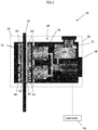
FIG. 2 is a cross-sectional view of an embodiment of a car or counterweight mounted friction damper of an elevator system; -
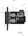
FIG. 3 is another cross-sectional view of an embodiment of a car or counterweight mounted friction damper of an elevator system; -
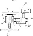
FIG. 4 is another cross-sectional view of an embodiment of a car or counterweight mounted friction damper of an elevator system; -
FIG. 5 is a cross-sectional view of another embodiment of a car or counterweight mounted friction damper of an elevator system; and -
FIG. 6 is a cross-sectional view of yet another embodiment of a car or counterweight mounted friction damper of an elevator system. - A detailed description of one or more embodiments of the disclosed apparatus and method are presented herein by way of exemplification and not limitation with reference to the Figures.
- Shown in
FIG. 1 is a schematic view of an exemplarytraction elevator system 10. Theelevator system 10 includes anelevator car 14 operatively suspended or supported in ahoistway 12 with one ormore suspension members 16, for example, one or more belts. The one ormore suspension members 16 interact withsheaves elevator system 10. Sheave 18 is configured as a diverter, deflector or idler sheave andsheave 52 is configured as a traction sheave, driven by amachine 50. Movement of thetraction sheave 52 by themachine 50 drives, moves and/or propels (through traction) the one ormore suspension members 16 that are routed around thetraction sheave 52. Diverter, deflector oridler sheaves 18 are not driven by amachine 50, but help guide the one ormore suspension members 16 around the various components of theelevator system 10. The one ormore suspension members 16 could also be connected to acounterweight 22, which is used to help balance theelevator system 10 and reduce the difference in belt tension on both sides of the traction sheave during operation. Thesheaves - The
elevator system 10 further includes one or more compensation and tie-down members 24 extending from theelevator car 14 toward ahoistway pit 26 around a tie-downsheave 28 and up to thecounterweight 22. A tie-down mass 30 is disposed in thehoistway pit 26 and affixed to the tie-downsheave 28. The compensation and tie-down members 24, tie-downsheave 28 and tie-down mass 30 stabilize motion of theelevator car 14 along thehoistway 12. - One or
more guide rails 32 are located in thehoistway 12 and extend along alength direction 34 of thehoistway 12. Theelevator car 14 is guided along the guide rails 32 by one or more car guides (not shown) located at theelevator car 14. Further, theelevator car 14 includes one or morefrictional dampers 38 at theelevator car 14, to hold theelevator car 14 at a selected position in thehoistway 12, preventing bounce or oscillation of theelevator car 14 by frictional engagement of thefrictional dampers 38 to theguide rail 32. - Referring now to
FIG. 2 , an embodiment of africtional damper 38 is illustrated. Thefrictional damper 38 includes afriction pad unit 40 operably coupled to anactuator unit 42. Thefriction pads unit 40 includes two ormore friction pads 44 which are driven into and out of engagement with theguide rail 32 by theactuator unit 42. In some embodiments, theactuator unit 42 acts in response to signals from anelevator system controller 46. - The
actuator unit 42 includes one or morehydraulic actuators 48 connected to thefriction pads 44 to urge thefrictions pads 44 into and out of contact with theguide rail 32. Thehydraulic actuator 48 includes one ormore piston chambers 54 containing a volume of hydraulic fluid. Ahydraulic piston 56 is disposed in thepiston chamber 54 and is located at thefriction pads 44 to control movement of thefriction pads 44. A directelectromagnetic actuator 58 is connected to thehydraulic actuator 48 such that when theelectromagnetic actuator 58 is actuated, thepiston chamber 54 is pressurized, urging thehydraulic piston 56 to drive thefriction pads 44 into contact with theguide rail 32. When theelectromagnetic actuator 58 is deactivated, thehydraulic piston 56 reverses its movement, moving thefriction pads 44 out of contact with theguide rail 32. In some embodiments, one or more biasing members, such as springs or magnets, are disposed in an electromagnetic actuator housing to bias a position of the electromagnetic 58 actuator such that thefriction pads 44 are biased into and/or out of contact with theguide rail 32. - Referring now to
FIG. 3 , over time thefriction pads 44 wear, decreasing afriction pad thickness 60. To maintain asame air gap 62 between thefriction pad 44 and theguide rail 32 when thehydraulic actuator 48 and theelectromagnetic actuator 58 are in their respective retracted positons, additional hydraulic fluid is automatically introduced to thepiston chambers 54 from afluid reservoir 64 connected to thepiston chambers 54, to maintain a selected hydraulic fluid pressure in thepiston chambers 54, while also maintaining a consistent air gap, 62, for example, 4 millimeters, to compensate for wear of thefriction pads 44. -
FIG. 4 illustrates another view of the configuration of thefrictional damper 38 ofFIG. 3 . In this embodiment, thefrictional damper 38 is a single-side actuated configuration, with onehydraulic actuator 48 and oneelectromagnetic actuator 58, located at one lateral side of theguide rail 32. Thefriction pads 44 on opposing lateral sides of theguide rail 32 are connected by abracket 66 extending across theguide rail 32. - Another embodiment is illustrated in
FIG. 5 , in whichfriction pads 44 on each lateral side of theguide rail 32 are each connected to and driven by separatehydraulic actuator 48 andelectromagnetic actuator 58 arrangements. As shown inFIG. 5 , thehydraulic actuators 48 are connected to acommon fluid reservoir 64. It is to be appreciated, however, that in other embodiments separate hydraulic reservoirs may be utilized. - Referring now to
FIG. 6 ,friction pads 44 one each lateral side of theguide rail 32 are connected to and driven by separatehydraulic actuators 48. A commonelectromagnetic actuator 58 connected to bothhydraulic actuators 48 is utilized to drive operation of thehydraulic actuators 48. Theelectromagnetic actuator 58 is located at, for example, a first lateral side of theguide rail 32 and connected to thehydraulic actuator 48 at the opposing lateral side of theguide rail 32 by hydraulic fluid lines 68. As in the embodiment ofFIG. 5 , thehydraulic actuators 48 are connected to acommon fluid reservoir 64. It is to be appreciated, however, that in other embodiments separate hydraulic reservoirs may be utilized. - Referring again to
FIG. 2 , thefrictional damper 38 may include one or more sensors to detect and monitor various conditions of thefrictional damper 38. For example, afluid level sensor 70 is located at thefluid reservoir 64 to monitor fluid level of thefluid reservoir 64. A decrease in fluid level at thefluid reservoir 64 may be indicative of wear of thefriction pads 44, but ma also indicate leakage in thefrictional damper 38. Wearsensors 72 are located at thefriction pads 44 for a direct detection offriction pad 44 wear. When thefriction pad thickness 60 goes below a selected threshold, an alarm or other indication of a need to replace thefriction pads 44 will be triggered. Further, ahydraulic pressure sensor 74 is installed at, for example, thehydraulic actuator 48 to monitor hydraulic system pressure, which is indicative of force applied by thefrictional damper 38. - The
frictional damper 38 configurations disclosed herein present an easily adaptable, relatively low cost solution to managingfrictional damper 38 operation taking intoaccount friction pad 44 wear. - The term "about" is intended to include the degree of error associated with measurement of the particular quantity based upon the equipment available at the time of filing the application.
- The terminology used herein is for the purpose of describing particular embodiments only and is not intended to be limiting of the present disclosure. As used herein, the singular forms "a", "an" and "the" are intended to include the plural forms as well, unless the context clearly indicates otherwise. It will be further understood that the terms "comprises" and/or "comprising," when used in this specification, specify the presence of stated features, integers, steps, operations, elements, and/or components, but do not preclude the presence or addition of one or more other features, integers, steps, operations, element components, and/or groups thereof.
- While the present disclosure has been described with reference to an exemplary embodiment or embodiments, it will be understood by those skilled in the art that various changes may be made and equivalents may be substituted for elements thereof without departing from the scope of the present disclosure. In addition, many modifications may be made to adapt a particular situation or material to the teachings of the present disclosure without departing from the essential scope thereof. Therefore, it is intended that the present disclosure not be limited to the particular embodiment disclosed as the best mode contemplated for carrying out this present disclosure, but that the present disclosure will include all embodiments falling within the scope of the claims.
Claims (12)
- A frictional damper for an elevator system, comprising:one or more friction pads configured to move between a first position defined by an air gap between the one or more friction pads and a guide rail of an elevator system, and a second positon defined by engagement of the one or more friction pads to the guide rail; andan actuation unit to urge the one or more friction pads into and out of engagement with the guide rail, the actuation unit including:a hydraulic actuator operably connected to the one or more friction pads to urge movement of the one or more friction pads into and out of engagement with the guide rail via hydraulic fluid pressure, the hydraulic actuator including:a hydraulic cylinder containing a volume of hydraulic fluid; anda hydraulic piston disposed in the hydraulic cylinder and operably connected to the one or more friction pads;an electromagnetic actuator configured to selectably urge hydraulic fluid to apply a force to the hydraulic piston, thereby urging the movement of the one or more friction pads.
- The frictional damper of claim 1, wherein the fluid level in the hydraulic cylinder of the hydraulic actuator is increased to maintain a constant air gap between the one or more friction pads and the guide rail at the first position e.g. to compensate for wear of the one or more friction pads.
- The frictional damper of claim 2, wherein the air gap is four millimeters.
- The frictional damper of any preceding claim, wherein a first friction pad of the one or more friction pads is disposed at a first lateral side of the guide rail and a second friction pad of the one or more friction pads is disposed at a second lateral side of the guide rail, opposite the first lateral side.
- The frictional damper of claim 4, wherein the hydraulic actuator and the electromagnetic actuator are both disposed at the first lateral side and operably connected to the first friction pad.
- The frictional damper of claim 4 or 5, further comprising:a first actuation unit operably connected to the first friction pad; anda second actuation unit operably connected to the second friction pad.
- The frictional damper of claim 4 or 5, wherein the actuation unit includes:a first hydraulic actuator operably connected to the first friction pad;a second hydraulic actuator operably connected to the second friction pad; anda shared electromagnetic actuator operably connected to each of the first hydraulic cylinder and the second hydraulic cylinder.
- The frictional damper of any preceding claim, further comprising one or more pad wear sensors disposed at the one or more friction pads.
- The frictional damper any preceding of claim, wherein a position of the friction pads is biased to the first position via one or more biasing members disposed at the electromagnetic actuator.
- The frictional damper of any preceding claim, further comprising a hydraulic reservoir in fluid communication with the hydraulic actuator, the hydraulic reservoir configured to increase a fluid level in the hydraulic cylinder to compensate for wear of the one or more friction pads.
- The frictional damper of claim 10, further comprising a fluid level sensor disposed at the hydraulic reservoir.
- An elevator system, comprising:an elevator car disposed in hoistway and movable along the hoistway; anda frictional damper disposed at the elevator car, according to any preceding claim.
Applications Claiming Priority (1)
| Application Number | Priority Date | Filing Date | Title |
|---|---|---|---|
| US16/050,307 US11203510B2 (en) | 2018-07-31 | 2018-07-31 | Electrohydraulic damper for elevator system |
Publications (2)
| Publication Number | Publication Date |
|---|---|
| EP3628628A1 true EP3628628A1 (en) | 2020-04-01 |
| EP3628628B1 EP3628628B1 (en) | 2023-12-06 |
Family
ID=67514374
Family Applications (1)
| Application Number | Title | Priority Date | Filing Date |
|---|---|---|---|
| EP19189321.3A Active EP3628628B1 (en) | 2018-07-31 | 2019-07-31 | Electrohydraulic damper for elevator system |
Country Status (4)
| Country | Link |
|---|---|
| US (1) | US11203510B2 (en) |
| EP (1) | EP3628628B1 (en) |
| CN (1) | CN110775770B (en) |
| ES (1) | ES2965623T3 (en) |
Families Citing this family (2)
| Publication number | Priority date | Publication date | Assignee | Title |
|---|---|---|---|---|
| EP3388380B1 (en) * | 2017-04-12 | 2020-10-07 | KONE Corporation | Method and elevator |
| CN120265565A (en) * | 2022-12-01 | 2025-07-04 | 因温特奥股份公司 | Braking device for braking the traveling basket of an elevator device |
Citations (2)
| Publication number | Priority date | Publication date | Assignee | Title |
|---|---|---|---|---|
| US6193026B1 (en) * | 1997-12-22 | 2001-02-27 | Otis Elevator Company | Elevator brake |
| EP1323660A1 (en) * | 2001-12-24 | 2003-07-02 | Inventio Ag | Safety brake for elevator system |
Family Cites Families (24)
| Publication number | Priority date | Publication date | Assignee | Title |
|---|---|---|---|---|
| GB1277986A (en) | 1970-03-20 | 1972-06-14 | Westinghouse Electric Corp | Improvements in or relating to an electrohydraulic brake control system |
| CA978874A (en) | 1973-07-05 | 1975-12-02 | Aimco Industries Limited | Electro-hydraulic disc brake |
| DE2757081C3 (en) | 1977-12-21 | 1980-09-18 | Gurij Sergeevitsch Bogatyrev | Electro-hydraulic shift drive |
| JP3067787B2 (en) | 1990-08-10 | 2000-07-24 | マツダ株式会社 | Hydraulically actuated compound brake system |
| ES2129480T3 (en) * | 1993-10-18 | 1999-06-16 | Inventio Ag | BRAKING SAFETY DEVICE FOR ELEVATOR CABINS. |
| US5601163A (en) * | 1996-03-05 | 1997-02-11 | Iri International Corporation | Automatic adjuster for brake calipers |
| US6033034A (en) | 1997-09-26 | 2000-03-07 | Elkins; Bert V. | Electrical, mechanical system for activating a hydraulic brake system |
| CN2784387Y (en) | 2005-03-22 | 2006-05-31 | 徐时金 | Electrohydraulic pushed caliper disk brake |
| DE102008037720A1 (en) | 2008-08-14 | 2010-02-18 | Ipgate Ag | Hydraulically acting brake system for vehicle, has master brake cylinder, whose working space is connected with wheel brake or parking brake of vehicle by hydraulic line |
| WO2011113753A2 (en) * | 2010-03-18 | 2011-09-22 | Inventio Ag | Elevator system having a brake device |
| EP2655233B1 (en) | 2010-12-22 | 2017-04-26 | Otis Elevator Company | Frictional damper for reducing elevator car movement |
| FI20125657L (en) | 2012-06-14 | 2013-12-15 | Kone Corp | A method for modernizing a hydraulic lift |
| CN104583109B (en) * | 2012-08-02 | 2016-09-21 | 奥的斯电梯公司 | Hydraulic braking system for elevators |
| CN202732804U (en) | 2012-08-20 | 2013-02-13 | 同济大学 | Intelligent brake capable of realizing smooth braking |
| EP2920100B1 (en) * | 2012-11-15 | 2024-01-10 | Otis Elevator Company | Elevator brake |
| DE102013014124A1 (en) | 2013-08-23 | 2014-08-28 | Audi Ag | Hydraulic actuator for actuating retainer brake lining of fixed caliper brake of e.g. commercial vehicle, has pistons magnetically influenced, where movements of pistons are additionally electromagnetically controllable |
| FI124983B (en) | 2013-10-29 | 2015-04-15 | Kone Corp | Damping arrangement to attenuate the opening noise of the machine brake on the lifting machinery of a lift, lifting machine for lifts and lift |
| CN203976292U (en) | 2014-06-30 | 2014-12-03 | 焦作制动器股份有限公司 | A kind of Intelligent brake device for crane hoisting mechanism |
| CN104444919B (en) | 2014-12-10 | 2016-10-05 | 洛阳源创电气有限公司 | Mine hoist constant deceleration brake electrichydraulic control equipment that can be anti-skidding |
| AU2016307263B2 (en) * | 2015-08-12 | 2019-07-18 | Inventio Ag | Anti-lock braking arrangement for an elevator and method for controlling same |
| CN108430905B (en) * | 2015-12-23 | 2019-12-27 | 因温特奥股份公司 | Optical brake lining monitoring |
| DE102016001577A1 (en) | 2016-02-11 | 2017-08-17 | Wabco Europe Bvba | A method for Lüftspielerkennung in a brake of a motor vehicle, in particular utility vehicle, controller and brake with selbigem |
| IT201600130805A1 (en) * | 2016-12-23 | 2018-06-23 | Freni Brembo Spa | BRAKE-BY-WIRE AUTOMATIC BRAKING SYSTEM FOR VEHICLES |
| CN207226891U (en) | 2017-09-29 | 2018-04-13 | 康达电梯有限公司 | A kind of novel elevator brake |
-
2018
- 2018-07-31 US US16/050,307 patent/US11203510B2/en not_active Expired - Fee Related
-
2019
- 2019-07-30 CN CN201910694540.7A patent/CN110775770B/en active Active
- 2019-07-31 EP EP19189321.3A patent/EP3628628B1/en active Active
- 2019-07-31 ES ES19189321T patent/ES2965623T3/en active Active
Patent Citations (2)
| Publication number | Priority date | Publication date | Assignee | Title |
|---|---|---|---|---|
| US6193026B1 (en) * | 1997-12-22 | 2001-02-27 | Otis Elevator Company | Elevator brake |
| EP1323660A1 (en) * | 2001-12-24 | 2003-07-02 | Inventio Ag | Safety brake for elevator system |
Also Published As
| Publication number | Publication date |
|---|---|
| CN110775770A (en) | 2020-02-11 |
| CN110775770B (en) | 2021-11-30 |
| ES2965623T3 (en) | 2024-04-16 |
| US11203510B2 (en) | 2021-12-21 |
| EP3628628B1 (en) | 2023-12-06 |
| US20200039788A1 (en) | 2020-02-06 |
Similar Documents
| Publication | Publication Date | Title |
|---|---|---|
| US9321610B2 (en) | Frictional damper for reducing elevator car movement | |
| CN107792747B (en) | Elevator car stabilizing device | |
| CN107108159A (en) | With compensation device so that first roller is largely released from the lifter apparatus of load when elevator car is static | |
| EP3628628B1 (en) | Electrohydraulic damper for elevator system | |
| US12077410B2 (en) | Electronic actuation module for elevator safety brake system | |
| JP4888389B2 (en) | Elevator equipment | |
| US20140224594A1 (en) | Elevator braking system | |
| KR20040019269A (en) | Elevator device | |
| CN110790109B (en) | Electric safety actuator assembly for elevator system | |
| EP3854742B1 (en) | Climbing elevator | |
| US6216824B1 (en) | Semi-active elevator hitch | |
| KR20190031171A (en) | Elevator emergency stop systems | |
| US20190292015A1 (en) | Rope sway detection and mitigation for elevator system | |
| EP3372548A1 (en) | Elevator rope tension assembly with frictional damping | |
| JP2013142006A (en) | Guide assembly and elevator device | |
| EP3868696B1 (en) | Elevator system having an elevator brake assembly and a method of operating a brake assembly of an elevator | |
| CN110027966B (en) | Dynamic droop damping system of elevator car | |
| CN108349697A (en) | Suspension arrangement for elevator | |
| US11390490B2 (en) | Cantilevered climbing elevator | |
| US20060163010A1 (en) | Self-centering device for compensation ropes or chains of an elevator | |
| EP1612177A1 (en) | Self-centering device for compensation ropes or chains of an elevator | |
| JP2018030711A (en) | Elevator device | |
| HK1199235B (en) | Elevator braking system |
Legal Events
| Date | Code | Title | Description |
|---|---|---|---|
| PUAI | Public reference made under article 153(3) epc to a published international application that has entered the european phase |
Free format text: ORIGINAL CODE: 0009012 |
|
| STAA | Information on the status of an ep patent application or granted ep patent |
Free format text: STATUS: THE APPLICATION HAS BEEN PUBLISHED |
|
| AK | Designated contracting states |
Kind code of ref document: A1 Designated state(s): AL AT BE BG CH CY CZ DE DK EE ES FI FR GB GR HR HU IE IS IT LI LT LU LV MC MK MT NL NO PL PT RO RS SE SI SK SM TR |
|
| AX | Request for extension of the european patent |
Extension state: BA ME |
|
| STAA | Information on the status of an ep patent application or granted ep patent |
Free format text: STATUS: REQUEST FOR EXAMINATION WAS MADE |
|
| 17P | Request for examination filed |
Effective date: 20201001 |
|
| RBV | Designated contracting states (corrected) |
Designated state(s): AL AT BE BG CH CY CZ DE DK EE ES FI FR GB GR HR HU IE IS IT LI LT LU LV MC MK MT NL NO PL PT RO RS SE SI SK SM TR |
|
| GRAP | Despatch of communication of intention to grant a patent |
Free format text: ORIGINAL CODE: EPIDOSNIGR1 |
|
| STAA | Information on the status of an ep patent application or granted ep patent |
Free format text: STATUS: GRANT OF PATENT IS INTENDED |
|
| INTG | Intention to grant announced |
Effective date: 20230621 |
|
| GRAS | Grant fee paid |
Free format text: ORIGINAL CODE: EPIDOSNIGR3 |
|
| GRAA | (expected) grant |
Free format text: ORIGINAL CODE: 0009210 |
|
| STAA | Information on the status of an ep patent application or granted ep patent |
Free format text: STATUS: THE PATENT HAS BEEN GRANTED |
|
| AK | Designated contracting states |
Kind code of ref document: B1 Designated state(s): AL AT BE BG CH CY CZ DE DK EE ES FI FR GB GR HR HU IE IS IT LI LT LU LV MC MK MT NL NO PL PT RO RS SE SI SK SM TR |
|
| REG | Reference to a national code |
Ref country code: GB Ref legal event code: FG4D |
|
| REG | Reference to a national code |
Ref country code: CH Ref legal event code: EP |
|
| REG | Reference to a national code |
Ref country code: DE Ref legal event code: R096 Ref document number: 602019042687 Country of ref document: DE |
|
| REG | Reference to a national code |
Ref country code: IE Ref legal event code: FG4D |
|
| REG | Reference to a national code |
Ref country code: LT Ref legal event code: MG9D |
|
| PG25 | Lapsed in a contracting state [announced via postgrant information from national office to epo] |
Ref country code: GR Free format text: LAPSE BECAUSE OF FAILURE TO SUBMIT A TRANSLATION OF THE DESCRIPTION OR TO PAY THE FEE WITHIN THE PRESCRIBED TIME-LIMIT Effective date: 20240307 |
|
| REG | Reference to a national code |
Ref country code: NL Ref legal event code: MP Effective date: 20231206 |
|
| PG25 | Lapsed in a contracting state [announced via postgrant information from national office to epo] |
Ref country code: LT Free format text: LAPSE BECAUSE OF FAILURE TO SUBMIT A TRANSLATION OF THE DESCRIPTION OR TO PAY THE FEE WITHIN THE PRESCRIBED TIME-LIMIT Effective date: 20231206 |
|
| REG | Reference to a national code |
Ref country code: ES Ref legal event code: FG2A Ref document number: 2965623 Country of ref document: ES Kind code of ref document: T3 Effective date: 20240416 |
|
| PG25 | Lapsed in a contracting state [announced via postgrant information from national office to epo] |
Ref country code: LT Free format text: LAPSE BECAUSE OF FAILURE TO SUBMIT A TRANSLATION OF THE DESCRIPTION OR TO PAY THE FEE WITHIN THE PRESCRIBED TIME-LIMIT Effective date: 20231206 Ref country code: GR Free format text: LAPSE BECAUSE OF FAILURE TO SUBMIT A TRANSLATION OF THE DESCRIPTION OR TO PAY THE FEE WITHIN THE PRESCRIBED TIME-LIMIT Effective date: 20240307 Ref country code: BG Free format text: LAPSE BECAUSE OF FAILURE TO SUBMIT A TRANSLATION OF THE DESCRIPTION OR TO PAY THE FEE WITHIN THE PRESCRIBED TIME-LIMIT Effective date: 20240306 |
|
| REG | Reference to a national code |
Ref country code: AT Ref legal event code: MK05 Ref document number: 1638234 Country of ref document: AT Kind code of ref document: T Effective date: 20231206 |
|
| PG25 | Lapsed in a contracting state [announced via postgrant information from national office to epo] |
Ref country code: NL Free format text: LAPSE BECAUSE OF FAILURE TO SUBMIT A TRANSLATION OF THE DESCRIPTION OR TO PAY THE FEE WITHIN THE PRESCRIBED TIME-LIMIT Effective date: 20231206 |
|
| PG25 | Lapsed in a contracting state [announced via postgrant information from national office to epo] |
Ref country code: SE Free format text: LAPSE BECAUSE OF FAILURE TO SUBMIT A TRANSLATION OF THE DESCRIPTION OR TO PAY THE FEE WITHIN THE PRESCRIBED TIME-LIMIT Effective date: 20231206 Ref country code: RS Free format text: LAPSE BECAUSE OF FAILURE TO SUBMIT A TRANSLATION OF THE DESCRIPTION OR TO PAY THE FEE WITHIN THE PRESCRIBED TIME-LIMIT Effective date: 20231206 Ref country code: NO Free format text: LAPSE BECAUSE OF FAILURE TO SUBMIT A TRANSLATION OF THE DESCRIPTION OR TO PAY THE FEE WITHIN THE PRESCRIBED TIME-LIMIT Effective date: 20240306 Ref country code: NL Free format text: LAPSE BECAUSE OF FAILURE TO SUBMIT A TRANSLATION OF THE DESCRIPTION OR TO PAY THE FEE WITHIN THE PRESCRIBED TIME-LIMIT Effective date: 20231206 Ref country code: LV Free format text: LAPSE BECAUSE OF FAILURE TO SUBMIT A TRANSLATION OF THE DESCRIPTION OR TO PAY THE FEE WITHIN THE PRESCRIBED TIME-LIMIT Effective date: 20231206 Ref country code: HR Free format text: LAPSE BECAUSE OF FAILURE TO SUBMIT A TRANSLATION OF THE DESCRIPTION OR TO PAY THE FEE WITHIN THE PRESCRIBED TIME-LIMIT Effective date: 20231206 |
|
| PG25 | Lapsed in a contracting state [announced via postgrant information from national office to epo] |
Ref country code: IS Free format text: LAPSE BECAUSE OF FAILURE TO SUBMIT A TRANSLATION OF THE DESCRIPTION OR TO PAY THE FEE WITHIN THE PRESCRIBED TIME-LIMIT Effective date: 20240406 |
|
| PG25 | Lapsed in a contracting state [announced via postgrant information from national office to epo] |
Ref country code: AT Free format text: LAPSE BECAUSE OF FAILURE TO SUBMIT A TRANSLATION OF THE DESCRIPTION OR TO PAY THE FEE WITHIN THE PRESCRIBED TIME-LIMIT Effective date: 20231206 Ref country code: CZ Free format text: LAPSE BECAUSE OF FAILURE TO SUBMIT A TRANSLATION OF THE DESCRIPTION OR TO PAY THE FEE WITHIN THE PRESCRIBED TIME-LIMIT Effective date: 20231206 |
|
| PG25 | Lapsed in a contracting state [announced via postgrant information from national office to epo] |
Ref country code: SK Free format text: LAPSE BECAUSE OF FAILURE TO SUBMIT A TRANSLATION OF THE DESCRIPTION OR TO PAY THE FEE WITHIN THE PRESCRIBED TIME-LIMIT Effective date: 20231206 |
|
| PG25 | Lapsed in a contracting state [announced via postgrant information from national office to epo] |
Ref country code: SM Free format text: LAPSE BECAUSE OF FAILURE TO SUBMIT A TRANSLATION OF THE DESCRIPTION OR TO PAY THE FEE WITHIN THE PRESCRIBED TIME-LIMIT Effective date: 20231206 Ref country code: SK Free format text: LAPSE BECAUSE OF FAILURE TO SUBMIT A TRANSLATION OF THE DESCRIPTION OR TO PAY THE FEE WITHIN THE PRESCRIBED TIME-LIMIT Effective date: 20231206 Ref country code: RO Free format text: LAPSE BECAUSE OF FAILURE TO SUBMIT A TRANSLATION OF THE DESCRIPTION OR TO PAY THE FEE WITHIN THE PRESCRIBED TIME-LIMIT Effective date: 20231206 Ref country code: IT Free format text: LAPSE BECAUSE OF FAILURE TO SUBMIT A TRANSLATION OF THE DESCRIPTION OR TO PAY THE FEE WITHIN THE PRESCRIBED TIME-LIMIT Effective date: 20231206 Ref country code: IS Free format text: LAPSE BECAUSE OF FAILURE TO SUBMIT A TRANSLATION OF THE DESCRIPTION OR TO PAY THE FEE WITHIN THE PRESCRIBED TIME-LIMIT Effective date: 20240406 Ref country code: EE Free format text: LAPSE BECAUSE OF FAILURE TO SUBMIT A TRANSLATION OF THE DESCRIPTION OR TO PAY THE FEE WITHIN THE PRESCRIBED TIME-LIMIT Effective date: 20231206 Ref country code: CZ Free format text: LAPSE BECAUSE OF FAILURE TO SUBMIT A TRANSLATION OF THE DESCRIPTION OR TO PAY THE FEE WITHIN THE PRESCRIBED TIME-LIMIT Effective date: 20231206 Ref country code: AT Free format text: LAPSE BECAUSE OF FAILURE TO SUBMIT A TRANSLATION OF THE DESCRIPTION OR TO PAY THE FEE WITHIN THE PRESCRIBED TIME-LIMIT Effective date: 20231206 |
|
| PGFP | Annual fee paid to national office [announced via postgrant information from national office to epo] |
Ref country code: FR Payment date: 20240619 Year of fee payment: 6 |
|
| PG25 | Lapsed in a contracting state [announced via postgrant information from national office to epo] |
Ref country code: PL Free format text: LAPSE BECAUSE OF FAILURE TO SUBMIT A TRANSLATION OF THE DESCRIPTION OR TO PAY THE FEE WITHIN THE PRESCRIBED TIME-LIMIT Effective date: 20231206 Ref country code: PT Free format text: LAPSE BECAUSE OF FAILURE TO SUBMIT A TRANSLATION OF THE DESCRIPTION OR TO PAY THE FEE WITHIN THE PRESCRIBED TIME-LIMIT Effective date: 20240408 |
|
| PG25 | Lapsed in a contracting state [announced via postgrant information from national office to epo] |
Ref country code: PT Free format text: LAPSE BECAUSE OF FAILURE TO SUBMIT A TRANSLATION OF THE DESCRIPTION OR TO PAY THE FEE WITHIN THE PRESCRIBED TIME-LIMIT Effective date: 20240408 Ref country code: PL Free format text: LAPSE BECAUSE OF FAILURE TO SUBMIT A TRANSLATION OF THE DESCRIPTION OR TO PAY THE FEE WITHIN THE PRESCRIBED TIME-LIMIT Effective date: 20231206 |
|
| REG | Reference to a national code |
Ref country code: DE Ref legal event code: R097 Ref document number: 602019042687 Country of ref document: DE |
|
| PGFP | Annual fee paid to national office [announced via postgrant information from national office to epo] |
Ref country code: DE Payment date: 20240619 Year of fee payment: 6 |
|
| PG25 | Lapsed in a contracting state [announced via postgrant information from national office to epo] |
Ref country code: DK Free format text: LAPSE BECAUSE OF FAILURE TO SUBMIT A TRANSLATION OF THE DESCRIPTION OR TO PAY THE FEE WITHIN THE PRESCRIBED TIME-LIMIT Effective date: 20231206 |
|
| PLBE | No opposition filed within time limit |
Free format text: ORIGINAL CODE: 0009261 |
|
| STAA | Information on the status of an ep patent application or granted ep patent |
Free format text: STATUS: NO OPPOSITION FILED WITHIN TIME LIMIT |
|
| PG25 | Lapsed in a contracting state [announced via postgrant information from national office to epo] |
Ref country code: SI Free format text: LAPSE BECAUSE OF FAILURE TO SUBMIT A TRANSLATION OF THE DESCRIPTION OR TO PAY THE FEE WITHIN THE PRESCRIBED TIME-LIMIT Effective date: 20231206 |
|
| PG25 | Lapsed in a contracting state [announced via postgrant information from national office to epo] |
Ref country code: SI Free format text: LAPSE BECAUSE OF FAILURE TO SUBMIT A TRANSLATION OF THE DESCRIPTION OR TO PAY THE FEE WITHIN THE PRESCRIBED TIME-LIMIT Effective date: 20231206 Ref country code: DK Free format text: LAPSE BECAUSE OF FAILURE TO SUBMIT A TRANSLATION OF THE DESCRIPTION OR TO PAY THE FEE WITHIN THE PRESCRIBED TIME-LIMIT Effective date: 20231206 |
|
| 26N | No opposition filed |
Effective date: 20240909 |
|
| PG25 | Lapsed in a contracting state [announced via postgrant information from national office to epo] |
Ref country code: MC Free format text: LAPSE BECAUSE OF FAILURE TO SUBMIT A TRANSLATION OF THE DESCRIPTION OR TO PAY THE FEE WITHIN THE PRESCRIBED TIME-LIMIT Effective date: 20231206 |
|
| REG | Reference to a national code |
Ref country code: CH Ref legal event code: PL |
|
| PG25 | Lapsed in a contracting state [announced via postgrant information from national office to epo] |
Ref country code: LU Free format text: LAPSE BECAUSE OF NON-PAYMENT OF DUE FEES Effective date: 20240731 |
|
| GBPC | Gb: european patent ceased through non-payment of renewal fee |
Effective date: 20240731 |
|
| PG25 | Lapsed in a contracting state [announced via postgrant information from national office to epo] |
Ref country code: LU Free format text: LAPSE BECAUSE OF NON-PAYMENT OF DUE FEES Effective date: 20240731 |
|
| PG25 | Lapsed in a contracting state [announced via postgrant information from national office to epo] |
Ref country code: BE Free format text: LAPSE BECAUSE OF NON-PAYMENT OF DUE FEES Effective date: 20240731 Ref country code: CH Free format text: LAPSE BECAUSE OF NON-PAYMENT OF DUE FEES Effective date: 20240731 |
|
| PG25 | Lapsed in a contracting state [announced via postgrant information from national office to epo] |
Ref country code: GB Free format text: LAPSE BECAUSE OF NON-PAYMENT OF DUE FEES Effective date: 20240731 |
|
| REG | Reference to a national code |
Ref country code: BE Ref legal event code: MM Effective date: 20240731 |
|
| PG25 | Lapsed in a contracting state [announced via postgrant information from national office to epo] |
Ref country code: IE Free format text: LAPSE BECAUSE OF NON-PAYMENT OF DUE FEES Effective date: 20240731 |
|
| REG | Reference to a national code |
Ref country code: ES Ref legal event code: FD2A Effective date: 20250829 |
|
| PG25 | Lapsed in a contracting state [announced via postgrant information from national office to epo] |
Ref country code: FI Free format text: LAPSE BECAUSE OF FAILURE TO SUBMIT A TRANSLATION OF THE DESCRIPTION OR TO PAY THE FEE WITHIN THE PRESCRIBED TIME-LIMIT Effective date: 20231207 |
|
| PG25 | Lapsed in a contracting state [announced via postgrant information from national office to epo] |
Ref country code: ES Free format text: LAPSE BECAUSE OF NON-PAYMENT OF DUE FEES Effective date: 20240801 |
|
| PG25 | Lapsed in a contracting state [announced via postgrant information from national office to epo] |
Ref country code: CY Free format text: LAPSE BECAUSE OF FAILURE TO SUBMIT A TRANSLATION OF THE DESCRIPTION OR TO PAY THE FEE WITHIN THE PRESCRIBED TIME-LIMIT; INVALID AB INITIO Effective date: 20190731 |
|
| REG | Reference to a national code |
Ref country code: DE Ref legal event code: R119 Ref document number: 602019042687 Country of ref document: DE |
|
| PG25 | Lapsed in a contracting state [announced via postgrant information from national office to epo] |
Ref country code: HU Free format text: LAPSE BECAUSE OF FAILURE TO SUBMIT A TRANSLATION OF THE DESCRIPTION OR TO PAY THE FEE WITHIN THE PRESCRIBED TIME-LIMIT; INVALID AB INITIO Effective date: 20190731 |
|
| PG25 | Lapsed in a contracting state [announced via postgrant information from national office to epo] |
Ref country code: DE Free format text: LAPSE BECAUSE OF NON-PAYMENT OF DUE FEES Effective date: 20260203 |
|
| PG25 | Lapsed in a contracting state [announced via postgrant information from national office to epo] |
Ref country code: FR Free format text: LAPSE BECAUSE OF NON-PAYMENT OF DUE FEES Effective date: 20250731 |