EP3628566A1 - Adjustable steering column assembly - Google Patents
Adjustable steering column assembly Download PDFInfo
- Publication number
- EP3628566A1 EP3628566A1 EP19199530.7A EP19199530A EP3628566A1 EP 3628566 A1 EP3628566 A1 EP 3628566A1 EP 19199530 A EP19199530 A EP 19199530A EP 3628566 A1 EP3628566 A1 EP 3628566A1
- Authority
- EP
- European Patent Office
- Prior art keywords
- rake
- guide
- attachment portion
- rake guide
- steering column
- Prior art date
- Legal status (The legal status is an assumption and is not a legal conclusion. Google has not performed a legal analysis and makes no representation as to the accuracy of the status listed.)
- Withdrawn
Links
- 230000000295 complement effect Effects 0.000 claims abstract description 17
- 230000008878 coupling Effects 0.000 claims abstract 4
- 238000010168 coupling process Methods 0.000 claims abstract 4
- 238000005859 coupling reaction Methods 0.000 claims abstract 4
- 239000000314 lubricant Substances 0.000 claims description 45
- 238000000576 coating method Methods 0.000 claims description 32
- 239000011248 coating agent Substances 0.000 claims description 29
- OKTJSMMVPCPJKN-UHFFFAOYSA-N Carbon Chemical compound [C] OKTJSMMVPCPJKN-UHFFFAOYSA-N 0.000 claims description 4
- 229910002804 graphite Inorganic materials 0.000 claims description 4
- 239000010439 graphite Substances 0.000 claims description 4
- 230000003993 interaction Effects 0.000 claims description 4
- 239000004922 lacquer Substances 0.000 claims description 4
- CWQXQMHSOZUFJS-UHFFFAOYSA-N molybdenum disulfide Chemical compound S=[Mo]=S CWQXQMHSOZUFJS-UHFFFAOYSA-N 0.000 claims description 4
- 229920001343 polytetrafluoroethylene Polymers 0.000 claims description 4
- -1 polytetrafluorethylene Polymers 0.000 claims description 3
- 239000004519 grease Substances 0.000 description 6
- 239000002131 composite material Substances 0.000 description 4
- 229910052751 metal Inorganic materials 0.000 description 4
- 239000002184 metal Substances 0.000 description 4
- 230000000712 assembly Effects 0.000 description 3
- 238000000429 assembly Methods 0.000 description 3
- 239000000463 material Substances 0.000 description 2
- 239000000203 mixture Substances 0.000 description 2
- 239000010687 lubricating oil Substances 0.000 description 1
- 238000000034 method Methods 0.000 description 1
- 230000001105 regulatory effect Effects 0.000 description 1
Images




Classifications
-
- B—PERFORMING OPERATIONS; TRANSPORTING
- B62—LAND VEHICLES FOR TRAVELLING OTHERWISE THAN ON RAILS
- B62D—MOTOR VEHICLES; TRAILERS
- B62D1/00—Steering controls, i.e. means for initiating a change of direction of the vehicle
- B62D1/02—Steering controls, i.e. means for initiating a change of direction of the vehicle vehicle-mounted
- B62D1/16—Steering columns
- B62D1/18—Steering columns yieldable or adjustable, e.g. tiltable
- B62D1/181—Steering columns yieldable or adjustable, e.g. tiltable with power actuated adjustment, e.g. with position memory
-
- B—PERFORMING OPERATIONS; TRANSPORTING
- B62—LAND VEHICLES FOR TRAVELLING OTHERWISE THAN ON RAILS
- B62D—MOTOR VEHICLES; TRAILERS
- B62D1/00—Steering controls, i.e. means for initiating a change of direction of the vehicle
- B62D1/02—Steering controls, i.e. means for initiating a change of direction of the vehicle vehicle-mounted
- B62D1/16—Steering columns
- B62D1/18—Steering columns yieldable or adjustable, e.g. tiltable
- B62D1/184—Mechanisms for locking columns at selected positions
-
- B—PERFORMING OPERATIONS; TRANSPORTING
- B62—LAND VEHICLES FOR TRAVELLING OTHERWISE THAN ON RAILS
- B62D—MOTOR VEHICLES; TRAILERS
- B62D1/00—Steering controls, i.e. means for initiating a change of direction of the vehicle
- B62D1/02—Steering controls, i.e. means for initiating a change of direction of the vehicle vehicle-mounted
- B62D1/16—Steering columns
- B62D1/18—Steering columns yieldable or adjustable, e.g. tiltable
- B62D1/183—Steering columns yieldable or adjustable, e.g. tiltable adjustable between in-use and out-of-use positions, e.g. to improve access
-
- B—PERFORMING OPERATIONS; TRANSPORTING
- B62—LAND VEHICLES FOR TRAVELLING OTHERWISE THAN ON RAILS
- B62D—MOTOR VEHICLES; TRAILERS
- B62D1/00—Steering controls, i.e. means for initiating a change of direction of the vehicle
- B62D1/02—Steering controls, i.e. means for initiating a change of direction of the vehicle vehicle-mounted
- B62D1/16—Steering columns
- B62D1/18—Steering columns yieldable or adjustable, e.g. tiltable
- B62D1/187—Steering columns yieldable or adjustable, e.g. tiltable with tilt adjustment; with tilt and axial adjustment
-
- B—PERFORMING OPERATIONS; TRANSPORTING
- B62—LAND VEHICLES FOR TRAVELLING OTHERWISE THAN ON RAILS
- B62D—MOTOR VEHICLES; TRAILERS
- B62D1/00—Steering controls, i.e. means for initiating a change of direction of the vehicle
- B62D1/02—Steering controls, i.e. means for initiating a change of direction of the vehicle vehicle-mounted
- B62D1/16—Steering columns
- B62D1/18—Steering columns yieldable or adjustable, e.g. tiltable
- B62D1/19—Steering columns yieldable or adjustable, e.g. tiltable incorporating energy-absorbing arrangements, e.g. by being yieldable or collapsible
- B62D1/195—Yieldable supports for the steering column
Definitions
- the disclosure relates generally to the field of steering column assemblies for motor vehicles. More specifically, the disclosure relates to adjustable steering column assemblies.
- an adjustable steering column assembly includes a lower jacket, a rake bracket, a rake guide, and a fastener.
- the lower jacket has an attachment portion with an end, and a passage extends from the attachment portion end at least partially through the attachment portion.
- the attachment portion end has upper and lower seating faces extending into the passage.
- the rake bracket has a base portion with an arm extending therefrom, and the arm has an aperture.
- the rake guide has upper and lower ends and a hole.
- the upper end has a configuration complementary to a configuration of the upper seating face
- the lower end has a configuration complementary to a configuration of the lower seating face
- the rake guide is positioned in the end of the lower jacket attachment portion such that the rake guide upper end mates with the upper seating face and such that the rake guide lower end mates with the lower seating face.
- the fastener couples the lower jacket, the rake bracket, and the rake guide, and the fastener passes through the aperture of the rake bracket, the hole of the rake guide, and past the rake guide in the passage.
- At least one of the following items includes a low friction coating: the upper seating face of the attachment portion end, the lower seating face of the attachment portion end, the upper end of the rake guide, and the lower end of the rake guide.
- the low friction coating includes at least one of the following items: sliding lacquer, polytetrafluoretylene (PTFE), molybdenum disulphide, a plasmapolymeric coating, and graphite.
- sliding lacquer polytetrafluoretylene (PTFE)
- PTFE polytetrafluoretylene
- molybdenum disulphide molybdenum disulphide
- plasmapolymeric coating a plasmapolymeric coating
- graphite graphite
- At least one of the following items includes a lubricant pocket containing a lubricant: the upper seating face of the attachment portion end, the lower seating face of the attachment portion end, the upper end of the rake guide, and the lower end of the rake guide.
- the attachment portion lower end has a guide rail protruding from the lower seating face and the rake guide has a guide rail protruding from the lower end.
- the guide rail of the rake guide has a configuration complementary to a configuration of the guide rail of the attachment portion lower end, and interaction between the guide rail of the rake guide and the guide rail of the attachment portion lower end aids in positioning the rake guide relative to the attachment portion lower end.
- the attachment portion end has an external perimeter formed by a continuous line in a single plane, and the upper and lower seating faces extend inwardly from the external perimeter into the passage.
- the rake guide upper end has a central curved area between rounded edge areas
- the rake guide lower end has a central curved area between rounded edge areas
- the guide rail of the rake guide protrudes from the central curved area of the rake guide lower end.
- the rake guide upper end has a central curved area between rounded edge areas
- the rake guide lower end has a central curved area between rounded edge areas
- the central curved area of the rake guide lower end includes at least one of the following items: a low friction coating, a lubricant pocket containing lubricant, and a guide rail.
- multiple pieces collectively form the rake guide.
- the rake guide is a unitary member.
- a second fastener is coaxial with the fastener, and the second fastener further couples the lower jacket to the rake bracket.
- the rake guide lower end and/or the rake guide upper end includes at least one of the following items: a low friction coating, a lubricant pocket containing lubricant, and a guide rail.
- the attachment portion has a guide rail protruding from the lower seating face.
- the rake guide has a guide rail protruding from the lower end.
- an adjustable steering column assembly includes a lower jacket, a rake bracket, a rake guide, and a fastener.
- the lower jacket has an attachment portion with an end, and the attachment portion end has upper and lower seating faces.
- the rake bracket has a base portion with an arm extending therefrom, and the arm has an aperture.
- the rake guide has upper and lower ends and a hole.
- the upper end has a configuration complementary to a configuration of the upper seating face
- the lower end has a configuration complementary to a configuration of the lower seating face
- the rake guide is positioned such that the rake guide upper end mates with the upper seating face and such that the rake guide lower end mates with the lower seating face.
- the fastener couples the lower jacket, the rake bracket, and the rake guide, and the fastener passes through the aperture of the rake bracket and the hole of the rake guide.
- the rake guide lower end and/or the rake guide upper end includes at least one of the following items: a low friction coating and a lubricant pocket containing lubricant.
- the attachment portion has a guide rail protruding from the lower seating face.
- Steering lash refers to a condition in which a steering wheel may be turned through some part of a revolution without associated movement of a vehicle's adjustable (typically front) wheels. Excessive amounts of lash are undesirable, and steering wheel lash is regulated for safety purposes; example regulations are set forth at 49 CFR 393.209(b). Lash typically occurs due to clearance (either from design or wear) in joints between steering components. But while joints must be held together sufficiently rigidly to avoid excessive lash, too much rigidity between joins can inhibit adjustment of the steering system. Moreover, it may be desirable for joints to be adjustable (i.e., capable of being tuned), as such adjustment may counteract wear and extend system life. Adjustment may also be used provide a customized feel to the driver.
- FIGs. 1 through 9 illustrate an adjustable steering column assembly 100, according to one embodiment.
- the steering column assembly 100 broadly includes a mounting bracket 102, a lower jacket 110, an upper jacket 120, a spindle 130, an adjustment unit 140, and a rake bracket subassembly 150.
- the upper jacket 120 rotatably supports the spindle (or "steering shaft") 130
- the lower jacket 110 telescopically supports the upper jacket 120
- the rake bracket subassembly 150 supports the lower jacket 110 while allowing height or tilt of the lower jacket 110 (and thus the upper jacket 120 and the spindle 130) to be adjusted
- the mounting bracket 102 fastens the rake bracket subassembly 150 to a vehicle's chassis
- the adjustment unit 140 ultimately changes the position of the spindle 130 as desired (both in height/tilt and toward/away from the driver).
- the upper jacket 120 and the spindle 130 are coaxial along a longitudinal axis X1.
- the mounting bracket 102, the upper jacket 120, the spindle 130, and the adjustment unit 140 may be any such components which are currently known in steering column assemblies or which are later developed, and the lower jacket 110 may telescopically support the upper jacket 120 in any manner which is currently known or later developed or a non-telescoping configuration may be used.
- the adjustment unit 140 may, for example, have one portion 140a for adjusting height/tilt (e.g., with an electric motor and a driven spindle, a driven nut, or gearing to tilt the lower jacket 110 relative to the bracket 102) and another portion 140b for adjusting the spindle 130 along the longitudinal axis X1 (e.g., with an electric motor and a driven spindle, a driven nut, or gearing to move the upper jacket 120 along the longitudinal axis X1 relative to the lower jacket 110). While countless appropriate mounting brackets, upper jackets, spindles, and telescopic portions of lower jackets exist, examples are disclosed in U.S. Pat. No. 9,090,284 to Meyer and U.S. Pat. No.
- the lower jacket 110 has an attachment portion 112 (see FIGs. 3 through 6 ) which may, for example, be configured as a slot (as shown), and which defines a passage 113 having an axis X2 generally perpendicular and skew to the axis X1.
- the attachment portion 112 has opposed ends 112a, 112b, and the passage 113 may extend fully through the attachment portion 112.
- the ends 112a, 112b may preferably be substantially similar to, or mirror images of, one another.
- each end 112a, 112b is generally symmetrical about a vertical plane passing through the axis X2 while the axis X1 is positioned horizontally, and the ends 112a, 112b are substantially the same as one another. As such, only the end 112a is discussed in further specific detail.
- the end 112a has an external perimeter 114 and upper and lower seating faces 114a, 114b.
- the external perimeter 114 may be unbroken (i.e., formed by a continuous line in a single plane) and generally rectangular, and the upper and lower seating faces 114a, 114b extend inwardly from the external perimeter 114 into the passage 113.
- the passage 113 is generally defined by opposed sidewalls 113a, 113b which extend to the perimeter 114 and opposed top and bottom walls 113c, 113d, and the seating faces 114a, 114b in embodiment 100 include central curved areas 115a, 115b and rounded edge areas 116a, 116b.
- the low-friction coating 117b may include, for example, one or more of: sliding lacquer, polytetrafluorethylene (PTFE), molybdenum disulphide, a plasmapolymeric coating, and graphite.
- the rake bracket subassembly 150 has a bracket 152, rake guides 162, bushings 172 each having an axial portion 172a and a flange 172b, and a fastener 176.
- the bracket 152 (best shown in FIG. 3 ) has an upper (or "base") portion 153 with lateral ends 154a, 154b, and arms 155a, 155b extend downwardly from the respective ends 154a, 154b.
- Each arm 155a, 155b has a coaxial hole 156 sized to pass part of the fastener 176 therethrough, and the arms 155a, 155b are configured such that the arms 155a, 155b may extend on opposite sides of the attachment portion 112 when the holes 156 are aligned with the axis X2. It may be desirable for each of the arms 155a, 155b to have a generally planar interior face 157a, 157b, and for the generally planar interior faces 157a, 157b to be generally parallel to one another.
- each rake guide 162 has a generally planar distal face 163, opposed generally planar sides 164, upper and lower ends 165a, 165b, and a hole 168 configured to pass part of the fastener 176 therethrough.
- the distal face 163 has a seat 163a ( FIG. 4 ) for receiving the flange 172b ( FIG. 3 ) of a respective bushing 172.
- the upper and lower ends 165a, 165b are complementary to the seating faces 114a, 114b. More particularly, the upper and lower ends 165a, 165b have central curved areas 166a, 166b and rounded edge areas 167a, 167b that are respectively complementary to the central curved areas 115a, 115b and the rounded edge areas 116a, 116b.
- the low-friction coating 169b may include, for example, one or more of: sliding lacquer, polytetrafluorethylene (PTFE), molybdenum disulphide, a plasmapolymeric coating, and graphite.
- each upper end 165a abuts a respective upper seating face 114a (with the upper central curved areas 166a and the rounded edge areas 167a abutting the upper central curved areas 115a and the rounded edge areas 116a), each lower end 165b abuts a respective lower seating face 114b (with the lower central curved areas 166b and the rounded edge areas 167b abutting the lower central curved areas 115b and the rounded edge areas 116b), and the sides 164 abutting the sidewalls 113a, 113b.
- Positioning of the rake guides 162 in the attachment portion 112 may allow the rake guides 162 to move along the axis X2 while being generally constrained rotationally and in other linear directions.
- the coatings 117b, 169b may allow the rake guides 162 to be positioned with little friction or resistance.
- the bushings 172 are passed through the rake guide holes 168, the bracket holes 156 are aligned with the rake guide holes 168, and the fastener (e.g., bolt) 176 may pass through the bracket holes 156, the rake guide holes 168, and the passage 113 to fasten the rake bracket 152 to the lower jacket 110.
- the fastener 176 may be secured using a nut, by caulking an end of the fastener 176, or through any other appropriate device or method, whether now known or later developed.
- Use of the described embodiments may provide desirable steering lash performance. And if the lash performance becomes undesirable, the rake guides 162 and/or the bushings 172 may be replaced or repaired.
- the low friction between the rake guides 162 and the lower jacket attachment portion 112 e.g., resulting from the coatings 117b, 169b) may further aid in expanding the useful life of the adjustable steering column assembly 100.
- FIG. 10 shows another rake guide 262 according to an embodiment of the current disclosure, for use with the adjustable steering column assembly 100 as a replacement for the rake guide 162.
- the rake guide 262 is substantially similar to the rake guide 162 described above, except as specifically noted and/or shown, or as would be inherent. Further, those skilled in the art will appreciate that the embodiment 100 (including the rake guide 162) may be modified in various ways, such as through incorporating all or part of any of the various described embodiments, for example.
- reference numbers from 200 to 299 may be used to indicate elements corresponding to those discussed above numbered from 100 to 199 (e.g., sides 264 correspond generally to the sides 164; upper and lower ends 265a, 265b correspond generally to the upper and lower ends 165a, 165b; central curved areas 266a, 266b correspond generally to the central curved areas 166a, 166b; rounded edge areas 267a, 267b correspond generally to the rounded edge areas 167a, 167b; hole 268 corresponds generally to the hole 168; et cetera), though with any noted, shown, or inherent deviations.
- the rake guide 262 primarily differs from the rake guide 162 by including at least one lubricant pocket 261 on the central curved areas 266a, 266b.
- the rake guide 262 may include the lubricant pockets 261 on only one (not both) of the central curved areas 266a, 266b.
- Multiple lubricant pockets 261 may be located in a pattern or randomly, and may each be of the same or different shapes and sizes. But each of the lubricant pockets 261 extends inwardly away from the outer surface of the rake guide 262.
- the lubricant pockets 261 may include a grease lubricant 261a or a lubricating oil.
- the lubricant 261a in the lubricant pockets 261 may further reduce friction between the rake guide 262 and the lower jacket attachment portion 112.
- the lubricant pockets 261 and the grease lubricant 261a may be sufficient such that the rake guide 262 does not include a coating equivalent to the coating 169b.
- the rake guide 262 may include both a low-friction coating 269b substantially similar to the low-friction coating 169b and one or more of the lubricant pockets 261, as such embodiments may improve performance over embodiments which have neither the low-friction coating nor a lubricant pocket, which have only the low-friction coating, and which have only the lubricant pocket.
- FIGs. 11 and 12 show another rake guide 362 and attachment portion end 312a according to another embodiment of the current disclosure, for use with the adjustable steering column assembly 100 as a replacement for the rake guide 162 and the attachment portion end 112a.
- the rake guide 362 and the attachment portion end 312a are substantially similar to the rake guide 162 and the attachment portion end 112a described above, except as specifically noted and/or shown, or as would be inherent.
- the embodiment 100 including the rake guide 162 and the attachment portion end 112a
- reference numbers from 300 to 399 may be used to indicate elements corresponding to those discussed above numbered from 100 to 199 (e.g., sides 364 correspond generally to the sides 164; upper and lower ends 365a, 365b correspond generally to the upper and lower ends 165a, 165b; hole 368 corresponds generally to the hole 168; et cetera), though with any noted, shown, or inherent deviations.
- the rake guide 362 and the attachment portion end 312a primarily differ from the rake guide 162 and the attachment portion end 112a in the configuration used to seat the rake guide 362 in the attachment portion end 312a. More particularly, instead of having rounded and curved areas 166a, 166b, 167a, 167b which seat in a correspondingly-shaped end 112a (see FIGs. 4 and 8 ), the rake guide 362 has generally planar abutting faces 366a, 366b and the attachment portion end 312a has complementary upper and lower seating faces 314a, 314b.
- the rake guide 362 and/or the abutting faces 366a, 366b may include a low-friction coating 317b, 369b substantially similar to the low-friction coatings 117b, 169b.
- an embodiment 362' of the rake guide 362 may include at least one lubricant pocket 361 with lubricant 361a on the abutting faces 366a, 366b, substantially similar to the lubricant pockets 261 and the grease lubricant 261a.
- the rake guides 362, 362' may or may not have the low-friction coating 317b.
- FIG. 14 very simply illustrates another rake guide 462 for use with the adjustable steering column assembly 100 as a replacement for the rake guide 162.
- the primary teaching of the rake guide 462 is that the rake guide 462 may be constructed as multiple pieces 462a, 462b which are collectively used to form the rake guide 462. While the pieces 462a, 462b of the rake guide 462 are of generally the same size and mirror images to one another, in other embodiments one piece may be substantially larger than the other (and may, for example, define entire hole 468). This teaching of multiple pieces 462a, 462b collectively forming the rake guide 462 is equally applicable to the other rake guides disclosed herein, and those skilled in the art will appreciate that each may be modified in this way.
- FIGs. 15 and 16 show another rake guide 562 and attachment portion end 512a according to another embodiment of the current disclosure, for use with the adjustable steering column assembly 100 as a replacement for the rake guide 162 and the attachment portion end 112a.
- the rake guide 562 and the attachment portion end 512a are substantially similar to the rake guide 162 and the attachment portion end 112a described above, except as specifically noted and/or shown, or as would be inherent.
- the embodiment 100 including the rake guide 162 and the attachment portion end 112a
- reference numbers from 500 to 599 may be used to indicate elements corresponding to those discussed above numbered from 100 to 199 (e.g., upper and lower ends 565a, 565b correspond generally to the upper and lower ends 165a, 165b; central curved areas 566a, 566b correspond generally to the central curved areas 166a, 166b; attachment portion ends 512a, 512b correspond generally to the attachment portion ends 112a, 112b; seating faces 514a, 514b correspond generally to the seating faces 114a, 114b; et cetera), though with any noted, shown, or inherent deviations.
- upper and lower ends 565a, 565b correspond generally to the upper and lower ends 165a, 165b
- central curved areas 566a, 566b correspond generally to the central curved areas 166a, 166b
- attachment portion ends 512a, 512b correspond generally to the attachment portion ends 112a, 112b
- seating faces 514a, 514b correspond generally to the seating faces 114
- the rake guide 562 and the attachment portion ends 512a, 512b primarily differ from the rake guides 162 and the attachment portion ends 112a, 112b in the inclusion of guide protrusions (or "guide rails"). More particularly, a guide rail 561 extends from each central curved area 566a, 566b of the rake guide 562, and the seating faces 514a, 514b each include a guide rail 519 complementary to the guide rails 561. Interaction between the guide rails 561, 519 may help positioning and maintaining position of the rake guides 562. In some embodiments, only the lower seating faces 514b may include guide rails 519, and in such embodiments, the upper central curved areas 566a may or may not include guide rails 561. The guide rails thus form discrete contact sections between the rake guides and the seating faces.
- FIG. 17 illustrates that other configurations of rake guides 662 (different from the rake guides 562) may also include guide rails 661
- FIG. 18 illustrates that rake guides 762 (as well as any of the other rake guides disclosed herein) may have additional guide rails 761. If additional guides rails 761 are included, the corresponding seating faces may similarly include additional guide rails.
- FIG. 19 shows another attachment portion end 812a according to another embodiment of the current disclosure, for use with the adjustable steering column assembly 100 as a replacement for the attachment portion end 112a.
- the attachment portion end 812a is substantially similar to the attachment portion end 112a described above, except as specifically noted and/or shown, or as would be inherent. Further, those skilled in the art will appreciate that the embodiment 100 (including the attachment portion end 112a) may be modified in various ways, such as through incorporating all or part of any of the various described embodiments, for example.
- reference numbers from 800 to 899 may be used to indicate elements corresponding to those discussed above numbered from 100 to 199 (e.g., seating faces 814a, 814b correspond generally to seating faces 114a, 114b, et cetera), though with any noted, shown, or inherent deviations.
- the attachment portion end 812a primarily differs from the attachment portion end 112a in that at least one of the seating faces 814a, 814b includes at least one lubricant pocket 861 with lubricant 861a.
- the lubricant pockets 861 and the grease lubricant 861a may be substantially similar to the lubricant pockets 261 and the grease lubricant 261a discussed above.
- the seating faces 114a, 114b may or may not have the low-friction coating 369b if the lubricant pockets 861 and the grease lubricant 861a are included.
- the lubricant 861a in the lubricant pockets 861 may further reduce friction between the rake guide 162 and the lower jacket attachment portion end 812a.
- FIG. 20 very simply illustrates that instead of a single fastener 176 (e.g., a bolt or other appropriate fastener) being used to pin or otherwise secure the rake bracket assembly 150 to the lower jacket 110 (as shown in FIG. 6 ), multiple fasteners 176' (e.g., bolts or other appropriate fasteners) may be used.
- a single fastener 176 e.g., a bolt or other appropriate fastener
- multiple fasteners 176' e.g., bolts or other appropriate fasteners
Landscapes
- Engineering & Computer Science (AREA)
- Chemical & Material Sciences (AREA)
- Combustion & Propulsion (AREA)
- Transportation (AREA)
- Mechanical Engineering (AREA)
- Steering Controls (AREA)
Abstract
Description
- The disclosure relates generally to the field of steering column assemblies for motor vehicles. More specifically, the disclosure relates to adjustable steering column assemblies.
- The following presents a simplified summary of the disclosure in order to provide a basic understanding of some aspects of the disclosure. This summary is not an extensive overview of the disclosure. It is not intended to identify critical elements of the disclosure or to delineate the scope of the disclosure. Its sole purpose is to present some concepts of the disclosure in a simplified form as a prelude to the more detailed description that is presented elsewhere.
- According to an embodiment, an adjustable steering column assembly includes a lower jacket, a rake bracket, a rake guide, and a fastener. The lower jacket has an attachment portion with an end, and a passage extends from the attachment portion end at least partially through the attachment portion. The attachment portion end has upper and lower seating faces extending into the passage. The rake bracket has a base portion with an arm extending therefrom, and the arm has an aperture. The rake guide has upper and lower ends and a hole. The upper end has a configuration complementary to a configuration of the upper seating face, the lower end has a configuration complementary to a configuration of the lower seating face, and the rake guide is positioned in the end of the lower jacket attachment portion such that the rake guide upper end mates with the upper seating face and such that the rake guide lower end mates with the lower seating face. The fastener couples the lower jacket, the rake bracket, and the rake guide, and the fastener passes through the aperture of the rake bracket, the hole of the rake guide, and past the rake guide in the passage.
- In an embodiment, at least one of the following items includes a low friction coating: the upper seating face of the attachment portion end, the lower seating face of the attachment portion end, the upper end of the rake guide, and the lower end of the rake guide.
- In an embodiment, the low friction coating includes at least one of the following items: sliding lacquer, polytetrafluoretylene (PTFE), molybdenum disulphide, a plasmapolymeric coating, and graphite.
- In an embodiment, at least one of the following items includes a lubricant pocket containing a lubricant: the upper seating face of the attachment portion end, the lower seating face of the attachment portion end, the upper end of the rake guide, and the lower end of the rake guide.
- In an embodiment, the attachment portion lower end has a guide rail protruding from the lower seating face and the rake guide has a guide rail protruding from the lower end. The guide rail of the rake guide has a configuration complementary to a configuration of the guide rail of the attachment portion lower end, and interaction between the guide rail of the rake guide and the guide rail of the attachment portion lower end aids in positioning the rake guide relative to the attachment portion lower end.
- In an embodiment, the attachment portion end has an external perimeter formed by a continuous line in a single plane, and the upper and lower seating faces extend inwardly from the external perimeter into the passage.
- In an embodiment, the rake guide upper end has a central curved area between rounded edge areas, the rake guide lower end has a central curved area between rounded edge areas, and the guide rail of the rake guide protrudes from the central curved area of the rake guide lower end.
- In an embodiment, the rake guide upper end has a central curved area between rounded edge areas, the rake guide lower end has a central curved area between rounded edge areas, and the central curved area of the rake guide lower end includes at least one of the following items: a low friction coating, a lubricant pocket containing lubricant, and a guide rail.
- In an embodiment, multiple pieces collectively form the rake guide.
- In an embodiment, the rake guide is a unitary member.
- In an embodiment, a second fastener is coaxial with the fastener, and the second fastener further couples the lower jacket to the rake bracket.
- In an embodiment, the rake guide lower end and/or the rake guide upper end includes at least one of the following items: a low friction coating, a lubricant pocket containing lubricant, and a guide rail.
- In an embodiment, the attachment portion has a guide rail protruding from the lower seating face.
- In an embodiment, the rake guide has a guide rail protruding from the lower end.
- According to another embodiment, an adjustable steering column assembly includes a lower jacket, a rake bracket, a rake guide, and a fastener. The lower jacket has an attachment portion with an end, and the attachment portion end has upper and lower seating faces. The rake bracket has a base portion with an arm extending therefrom, and the arm has an aperture. The rake guide has upper and lower ends and a hole. The upper end has a configuration complementary to a configuration of the upper seating face, the lower end has a configuration complementary to a configuration of the lower seating face, and the rake guide is positioned such that the rake guide upper end mates with the upper seating face and such that the rake guide lower end mates with the lower seating face. The fastener couples the lower jacket, the rake bracket, and the rake guide, and the fastener passes through the aperture of the rake bracket and the hole of the rake guide. The rake guide lower end and/or the rake guide upper end includes at least one of the following items: a low friction coating and a lubricant pocket containing lubricant.
- In an embodiment, the attachment portion has a guide rail protruding from the lower seating face.
-
-
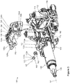
FIG. 1 is a perspective view showing an adjustable steering column assembly, according to an embodiment of the present disclosure. -
FIG. 2 is another perspective view showing the adjustable steering column assembly ofFIG. 1 . -
FIG. 3 is an exploded view showing the adjustable steering column assembly ofFIG. 1 . -
FIG. 4 is a partial view taken fromFIG. 3 . -
FIG. 5 is a section view illustrating a material composition of at least part of a lower jacket of the adjustable steering column assembly ofFIG. 1 . -
FIG. 6 is an end view of the adjustable steering column assembly ofFIG. 1 , with portions being shown in section for illustration. -
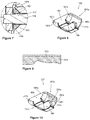
FIG. 7 is a partial view taken fromFIG. 6 . -
FIG. 8 is a perspective view of a rake guide of the adjustable steering column assembly ofFIG. 1 . -
FIG. 9 is a section view illustrating a material composition of at least part of the rake guide ofFIG. 8 . -
FIG. 10 is a perspective view of a rake guide, according to another embodiment of the present disclosure. -
FIG. 11 is a perspective view of a rake guide, according to still another embodiment of the present disclosure. -
FIG. 12 is a section view showing the rake guide ofFIG. 11 in use. -
FIGs 13 through 15 are perspective views of rake guides, according to still yet other embodiments of the present disclosure. -
FIG. 16 is an exploded view showing the rake guide ofFIG. 15 and an attachment portion, according to another embodiment of the present disclosure. -
FIGs 17 and 18 are perspective views of rake guides, according to still further embodiments of the present disclosure. -
FIG. 19 is an exploded view showing the rake guide ofFIG. 8 and an attachment portion, according to still another embodiment of the present disclosure. -
FIG. 20 is an end view with portions being shown in section for illustration, similar toFIG. 6 but with alternate fasteners. - Steering lash refers to a condition in which a steering wheel may be turned through some part of a revolution without associated movement of a vehicle's adjustable (typically front) wheels. Excessive amounts of lash are undesirable, and steering wheel lash is regulated for safety purposes; example regulations are set forth at 49 CFR 393.209(b). Lash typically occurs due to clearance (either from design or wear) in joints between steering components. But while joints must be held together sufficiently rigidly to avoid excessive lash, too much rigidity between joins can inhibit adjustment of the steering system. Moreover, it may be desirable for joints to be adjustable (i.e., capable of being tuned), as such adjustment may counteract wear and extend system life. Adjustment may also be used provide a customized feel to the driver.
-
FIGs. 1 through 9 illustrate an adjustablesteering column assembly 100, according to one embodiment. Thesteering column assembly 100 broadly includes amounting bracket 102, alower jacket 110, anupper jacket 120, aspindle 130, anadjustment unit 140, and a rake bracket subassembly 150. Broadly viewed, theupper jacket 120 rotatably supports the spindle (or "steering shaft") 130, thelower jacket 110 telescopically supports theupper jacket 120, the rake bracket subassembly 150 supports thelower jacket 110 while allowing height or tilt of the lower jacket 110 (and thus theupper jacket 120 and the spindle 130) to be adjusted, themounting bracket 102 fastens the rake bracket subassembly 150 to a vehicle's chassis, and theadjustment unit 140 ultimately changes the position of thespindle 130 as desired (both in height/tilt and toward/away from the driver). Theupper jacket 120 and thespindle 130 are coaxial along a longitudinal axis X1. - The mounting
bracket 102, theupper jacket 120, thespindle 130, and theadjustment unit 140 may be any such components which are currently known in steering column assemblies or which are later developed, and thelower jacket 110 may telescopically support theupper jacket 120 in any manner which is currently known or later developed or a non-telescoping configuration may be used. Theadjustment unit 140 may, for example, have oneportion 140a for adjusting height/tilt (e.g., with an electric motor and a driven spindle, a driven nut, or gearing to tilt thelower jacket 110 relative to the bracket 102) and anotherportion 140b for adjusting thespindle 130 along the longitudinal axis X1 (e.g., with an electric motor and a driven spindle, a driven nut, or gearing to move theupper jacket 120 along the longitudinal axis X1 relative to the lower jacket 110). While countless appropriate mounting brackets, upper jackets, spindles, and telescopic portions of lower jackets exist, examples are disclosed inU.S. Pat. No. 9,090,284 to Meyer U.S. Pat. No. 9,327,756 to Rauber spindle 130 may be manually or automatically adjusted for both height and length. - Focus is now directed to the
lower jacket 110 and therake bracket subassembly 150, which are more specifically shown inFIGs. 3 through 9 . Thelower jacket 110 has an attachment portion 112 (seeFIGs. 3 through 6 ) which may, for example, be configured as a slot (as shown), and which defines apassage 113 having an axis X2 generally perpendicular and skew to the axis X1. Theattachment portion 112 has opposed ends 112a, 112b, and thepassage 113 may extend fully through theattachment portion 112. Theends embodiment 100, eachend ends end 112a is discussed in further specific detail. - As shown in
FIG. 4 , theend 112a has anexternal perimeter 114 and upper and lower seating faces 114a, 114b. Theexternal perimeter 114 may be unbroken (i.e., formed by a continuous line in a single plane) and generally rectangular, and the upper and lower seating faces 114a, 114b extend inwardly from theexternal perimeter 114 into thepassage 113. Thepassage 113 is generally defined by opposed sidewalls 113a, 113b which extend to theperimeter 114 and opposed top andbottom walls embodiment 100 include centralcurved areas edge areas - It may be particularly desirable for the seating faces 114a, 114b and at least a portion of the sidewalls 113a, 113b adjacent the
perimeter 114 to have a low-friction (i.e., friction reducing)coating 117b over a metal or compositestructural core 117a (as shown inFIG. 5 ), and in some embodiments it may be desirable for theentire attachment portion 112 to have the metal orcomposite core 117a and the low-friction coating 117b. The low-friction coating 117b may include, for example, one or more of: sliding lacquer, polytetrafluorethylene (PTFE), molybdenum disulphide, a plasmapolymeric coating, and graphite. - Turning now to the
rake bracket subassembly 150, therake bracket subassembly 150 has abracket 152, rake guides 162,bushings 172 each having anaxial portion 172a and aflange 172b, and afastener 176. The bracket 152 (best shown inFIG. 3 ) has an upper (or "base")portion 153 withlateral ends arms respective ends arm coaxial hole 156 sized to pass part of thefastener 176 therethrough, and thearms arms attachment portion 112 when theholes 156 are aligned with the axis X2. It may be desirable for each of thearms interior face interior faces - In the
embodiment 100, the rake guides 162 are substantially similar to one another, just as theends ends FIGs. 4 and8 , eachrake guide 162 has a generally planardistal face 163, opposed generallyplanar sides 164, upper andlower ends hole 168 configured to pass part of thefastener 176 therethrough. Thedistal face 163 has aseat 163a (FIG. 4 ) for receiving theflange 172b (FIG. 3 ) of arespective bushing 172. And the upper andlower ends lower ends curved areas edge areas curved areas rounded edge areas - It may be particularly desirable for the upper and
lower ends sides 164 to have a low friction (i.e., friction reducing)coating 169b over a metal or compositestructural core 169a (as shown inFIG. 9 ), and in some embodiments it may be desirable for theentire rake guide 162 to have the metal orcomposite core 169a and thelow friction coating 169b. The low-friction coating 169b may include, for example, one or more of: sliding lacquer, polytetrafluorethylene (PTFE), molybdenum disulphide, a plasmapolymeric coating, and graphite. - In use, the rake guides 162 are respectively positioned in the lower
jacket attachment portion 112. More particularly, eachupper end 165a abuts a respectiveupper seating face 114a (with the upper centralcurved areas 166a and therounded edge areas 167a abutting the upper centralcurved areas 115a and therounded edge areas 116a), eachlower end 165b abuts a respectivelower seating face 114b (with the lower centralcurved areas 166b and therounded edge areas 167b abutting the lower centralcurved areas 115b and therounded edge areas 116b), and thesides 164 abutting the sidewalls 113a, 113b. Positioning of the rake guides 162 in theattachment portion 112 may allow the rake guides 162 to move along the axis X2 while being generally constrained rotationally and in other linear directions. Thecoatings - Once the rake guides 162 are in place, the
bushings 172 are passed through the rake guide holes 168, the bracket holes 156 are aligned with the rake guide holes 168, and the fastener (e.g., bolt) 176 may pass through the bracket holes 156, the rake guide holes 168, and thepassage 113 to fasten therake bracket 152 to thelower jacket 110. Thefastener 176 may be secured using a nut, by caulking an end of thefastener 176, or through any other appropriate device or method, whether now known or later developed. - Use of the described embodiments may provide desirable steering lash performance. And if the lash performance becomes undesirable, the rake guides 162 and/or the
bushings 172 may be replaced or repaired. The low friction between the rake guides 162 and the lower jacket attachment portion 112 (e.g., resulting from thecoatings steering column assembly 100. -
FIG. 10 shows anotherrake guide 262 according to an embodiment of the current disclosure, for use with the adjustablesteering column assembly 100 as a replacement for therake guide 162. Therake guide 262 is substantially similar to therake guide 162 described above, except as specifically noted and/or shown, or as would be inherent. Further, those skilled in the art will appreciate that the embodiment 100 (including the rake guide 162) may be modified in various ways, such as through incorporating all or part of any of the various described embodiments, for example. For uniformity and brevity, reference numbers from 200 to 299 may be used to indicate elements corresponding to those discussed above numbered from 100 to 199 (e.g., sides 264 correspond generally to thesides 164; upper andlower ends lower ends curved areas 266a, 266b correspond generally to the centralcurved areas edge areas rounded edge areas hole 268 corresponds generally to thehole 168; et cetera), though with any noted, shown, or inherent deviations. - The
rake guide 262 primarily differs from therake guide 162 by including at least onelubricant pocket 261 on the centralcurved areas 266a, 266b. In some embodiments, therake guide 262 may include the lubricant pockets 261 on only one (not both) of the centralcurved areas 266a, 266b. Multiple lubricant pockets 261 may be located in a pattern or randomly, and may each be of the same or different shapes and sizes. But each of the lubricant pockets 261 extends inwardly away from the outer surface of therake guide 262. The lubricant pockets 261 may include agrease lubricant 261a or a lubricating oil. In use, thelubricant 261a in the lubricant pockets 261 may further reduce friction between therake guide 262 and the lowerjacket attachment portion 112. In some embodiments, the lubricant pockets 261 and thegrease lubricant 261a may be sufficient such that therake guide 262 does not include a coating equivalent to thecoating 169b. In other embodiments, therake guide 262 may include both a low-friction coating 269b substantially similar to the low-friction coating 169b and one or more of the lubricant pockets 261, as such embodiments may improve performance over embodiments which have neither the low-friction coating nor a lubricant pocket, which have only the low-friction coating, and which have only the lubricant pocket. -
FIGs. 11 and 12 show anotherrake guide 362 andattachment portion end 312a according to another embodiment of the current disclosure, for use with the adjustablesteering column assembly 100 as a replacement for therake guide 162 and theattachment portion end 112a. Therake guide 362 and theattachment portion end 312a are substantially similar to therake guide 162 and theattachment portion end 112a described above, except as specifically noted and/or shown, or as would be inherent. Further, those skilled in the art will appreciate that the embodiment 100 (including therake guide 162 and theattachment portion end 112a) may be modified in various ways, such as through incorporating all or part of any of the various described embodiments, for example. For uniformity and brevity, reference numbers from 300 to 399 may be used to indicate elements corresponding to those discussed above numbered from 100 to 199 (e.g., sides 364 correspond generally to thesides 164; upper andlower ends lower ends hole 368 corresponds generally to thehole 168; et cetera), though with any noted, shown, or inherent deviations. - The
rake guide 362 and theattachment portion end 312a primarily differ from therake guide 162 and theattachment portion end 112a in the configuration used to seat therake guide 362 in theattachment portion end 312a. More particularly, instead of having rounded andcurved areas end 112a (seeFIGs. 4 and8 ), therake guide 362 has generally planar abutting faces 366a, 366b and theattachment portion end 312a has complementary upper and lower seating faces 314a, 314b. As with the other embodiments, therake guide 362 and/or the abutting faces 366a, 366b may include a low-friction coating friction coatings FIG. 13 , an embodiment 362' of therake guide 362 may include at least onelubricant pocket 361 withlubricant 361a on the abutting faces 366a, 366b, substantially similar to the lubricant pockets 261 and thegrease lubricant 261a. And, as discussed above regarding therake guide 262, the rake guides 362, 362' may or may not have the low-friction coating 317b. -
FIG. 14 very simply illustrates anotherrake guide 462 for use with the adjustablesteering column assembly 100 as a replacement for therake guide 162. The primary teaching of therake guide 462 is that therake guide 462 may be constructed asmultiple pieces 462a, 462b which are collectively used to form therake guide 462. While thepieces 462a, 462b of therake guide 462 are of generally the same size and mirror images to one another, in other embodiments one piece may be substantially larger than the other (and may, for example, define entire hole 468). This teaching ofmultiple pieces 462a, 462b collectively forming therake guide 462 is equally applicable to the other rake guides disclosed herein, and those skilled in the art will appreciate that each may be modified in this way. -
FIGs. 15 and 16 show anotherrake guide 562 andattachment portion end 512a according to another embodiment of the current disclosure, for use with the adjustablesteering column assembly 100 as a replacement for therake guide 162 and theattachment portion end 112a. Therake guide 562 and theattachment portion end 512a are substantially similar to therake guide 162 and theattachment portion end 112a described above, except as specifically noted and/or shown, or as would be inherent. Further, those skilled in the art will appreciate that the embodiment 100 (including therake guide 162 and theattachment portion end 112a) may be modified in various ways, such as through incorporating all or part of any of the various described embodiments, for example. For uniformity and brevity, reference numbers from 500 to 599 may be used to indicate elements corresponding to those discussed above numbered from 100 to 199 (e.g., upper andlower ends lower ends curved areas curved areas - The
rake guide 562 and the attachment portion ends 512a, 512b primarily differ from the rake guides 162 and the attachment portion ends 112a, 112b in the inclusion of guide protrusions (or "guide rails"). More particularly, aguide rail 561 extends from each centralcurved area rake guide 562, and the seating faces 514a, 514b each include aguide rail 519 complementary to the guide rails 561. Interaction between theguide rails guide rails 519, and in such embodiments, the upper centralcurved areas 566a may or may not include guide rails 561. The guide rails thus form discrete contact sections between the rake guides and the seating faces. -
FIG. 17 illustrates that other configurations of rake guides 662 (different from the rake guides 562) may also includeguide rails 661, andFIG. 18 illustrates that rake guides 762 (as well as any of the other rake guides disclosed herein) may have additional guide rails 761. Ifadditional guides rails 761 are included, the corresponding seating faces may similarly include additional guide rails. -
FIG. 19 shows anotherattachment portion end 812a according to another embodiment of the current disclosure, for use with the adjustablesteering column assembly 100 as a replacement for theattachment portion end 112a. Theattachment portion end 812a is substantially similar to theattachment portion end 112a described above, except as specifically noted and/or shown, or as would be inherent. Further, those skilled in the art will appreciate that the embodiment 100 (including theattachment portion end 112a) may be modified in various ways, such as through incorporating all or part of any of the various described embodiments, for example. For uniformity and brevity, reference numbers from 800 to 899 may be used to indicate elements corresponding to those discussed above numbered from 100 to 199 (e.g., seating faces 814a, 814b correspond generally to seating faces 114a, 114b, et cetera), though with any noted, shown, or inherent deviations. - The
attachment portion end 812a primarily differs from theattachment portion end 112a in that at least one of the seating faces 814a, 814b includes at least onelubricant pocket 861 withlubricant 861a. The lubricant pockets 861 and thegrease lubricant 861a may be substantially similar to the lubricant pockets 261 and thegrease lubricant 261a discussed above. And, as discussed above regarding therake guide 262, the seating faces 114a, 114b may or may not have the low-friction coating 369b if the lubricant pockets 861 and thegrease lubricant 861a are included. In use, thelubricant 861a in the lubricant pockets 861 may further reduce friction between therake guide 162 and the lower jacketattachment portion end 812a. -
FIG. 20 very simply illustrates that instead of a single fastener 176 (e.g., a bolt or other appropriate fastener) being used to pin or otherwise secure therake bracket assembly 150 to the lower jacket 110 (as shown inFIG. 6 ), multiple fasteners 176' (e.g., bolts or other appropriate fasteners) may be used. - Many different arrangements of the various components depicted, as well as components not shown, are possible without departing from the spirit and scope of the present invention. Embodiments of the present invention have been described with the intent to be illustrative rather than restrictive. Alternative embodiments will become apparent to those skilled in the art that do not depart from its scope. A skilled artisan may develop alternative means of implementing the aforementioned improvements without departing from the scope of the present invention. It will be understood that certain features and subcombinations are of utility and may be employed without reference to other features and subcombinations and are contemplated within the scope of the claims.
Claims (20)
- An adjustable steering column assembly, comprising:a lower jacket having an attachment portion with an end, a passage extending from the attachment portion end at least partially through the attachment portion, the attachment portion end having upper and lower seating faces extending into the passage;a rake bracket having a base portion with an arm extending therefrom, the arm having an aperture;a rake guide having upper and lower ends and a hole, the upper end having a configuration complementary to a configuration of the upper seating face, the lower end having a configuration complementary to a configuration of the lower seating face, the rake guide being positioned in the end of the lower jacket attachment portion such that the rake guide upper end mates with the upper seating face and such that the rake guide lower end mates with the lower seating face; anda fastener coupling the lower jacket, the rake bracket, and the rake guide, wherein the fastener passes through the aperture of the rake bracket, the hole of the rake guide, and past the rake guide in the passage.
- The adjustable steering column assembly of claim 1, wherein at least one item selected from the group consisting of the following includes a low friction coating:the upper seating face of the attachment portion end;the lower seating face of the attachment portion end;the upper end of the rake guide; andthe lower end of the rake guide.
- The adjustable steering column assembly of claim 2, wherein the low friction coating includes at least one item selected from the group consisting of: sliding lacquer, polytetrafluorethylene (PTFE), molybdenum disulphide, a plasmapolymeric coating, and graphite.
- The adjustable steering column assembly of claim 2, wherein at least one item selected from the group consisting of the following includes a lubricant pocket containing a lubricant:the upper seating face of the attachment portion end;the lower seating face of the attachment portion end;the upper end of the rake guide; andthe lower end of the rake guide.
- The adjustable steering column assembly of claim 4, wherein:the attachment portion lower end has a guide rail protruding from the lower seating face; andthe rake guide has a guide rail protruding from the lower end, the guide rail of the rake guide having a configuration complementary to a configuration of the guide rail of the attachment portion lower end, interaction between the guide rail of the rake guide and the guide rail of the attachment portion lower end aiding in positioning the rake guide relative to the attachment portion lower end.
- The adjustable steering column assembly of claim 5, wherein:the attachment portion end has an external perimeter formed by a continuous line in a single plane; andthe upper and lower seating faces extend inwardly from the external perimeter into the passage.
- The adjustable steering column assembly of claim 1, wherein at least one item selected from the group consisting of the following includes a lubricant pocket containing a lubricant:the upper seating face of the attachment portion end;the lower seating face of the attachment portion end;the upper end of the rake guide; andthe lower end of the rake guide.
- The adjustable steering column assembly of claim 1, wherein:the attachment portion lower end has a guide rail protruding from the lower seating face; andthe rake guide has a guide rail protruding from the lower end, the guide rail of the rake guide having a configuration complementary to a configuration of the guide rail of the attachment portion lower end, interaction between the guide rail of the rake guide and the guide rail of the attachment portion lower end aiding in positioning the rake guide relative to the attachment portion lower end.
- The adjustable steering column assembly of claim 8, wherein:the rake guide upper end has a central curved area between rounded edge areas;the rake guide lower end has a central curved area between rounded edge areas; andthe guide rail of the rake guide protrudes from the central curved area of the rake guide lower end.
- The adjustable steering column assembly of claim 1, wherein:the attachment portion end has an external perimeter formed by a continuous line in a single plane; andthe upper and lower seating faces extend inwardly from the external perimeter into the passage.
- The adjustable steering column assembly of claim 10, wherein:the rake guide upper end has a central curved area between rounded edge areas; andthe rake guide lower end has a central curved area between rounded edge areas.
- The adjustable steering column assembly of claim 1, wherein:the rake guide upper end has a central curved area between rounded edge areas;the rake guide lower end has a central curved area between rounded edge areas;the central curved area of the rake guide lower end includes at least one item selected from the group consisting of the following:a low friction coating;a lubricant pocket containing lubricant; anda guide rail.
- The adjustable steering column assembly of claim 12, wherein multiple pieces collectively form the rake guide.
- The adjustable steering column assembly of claim 12, wherein the rake guide is a unitary member.
- The adjustable steering column assembly of claim 1, further comprising a second fastener coaxial with the fastener, the second fastener further coupling the lower jacket to the rake bracket.
- The adjustable steering column assembly of claim 1, wherein at least one item selected from the group consisting of the rake guide lower end and rake guide upper end includes at least one item selected from the group consisting of the following:a low friction coating;a lubricant pocket containing lubricant; anda guide rail.
- The adjustable steering column assembly of claim 1, wherein the attachment portion has a guide rail protruding from the lower seating face.
- The adjustable steering column assembly of claim 1, wherein the rake guide has a guide rail protruding from the lower end.
- An adjustable steering column assembly, comprising:a lower jacket having an attachment portion with an end, the attachment portion end having upper and lower seating faces;a rake bracket having a base portion with an arm extending therefrom, the arm having an aperture;a rake guide having upper and lower ends and a hole, the upper end having a configuration complementary to a configuration of the upper seating face, the lower end having a configuration complementary to a configuration of the lower seating face, the rake guide being positioned such that the rake guide upper end mates with the upper seating face and such that the rake guide lower end mates with the lower seating face; anda fastener coupling the lower jacket, the rake bracket, and the rake guide, wherein the fastener passes through the aperture of the rake bracket and the hole of the rake guide;wherein at least one item selected from the group consisting of the rake guide lower end and the rake guide upper end includes at least one item selected from the group consisting of the following:a low friction coating; anda lubricant pocket containing lubricant.
- The adjustable steering column assembly of claim 19, wherein the attachment portion has a guide rail protruding from the lower seating face.
Applications Claiming Priority (1)
| Application Number | Priority Date | Filing Date | Title |
|---|---|---|---|
| US16/146,359 US10773746B2 (en) | 2018-09-28 | 2018-09-28 | Adjustable steering column assembly |
Publications (1)
| Publication Number | Publication Date |
|---|---|
| EP3628566A1 true EP3628566A1 (en) | 2020-04-01 |
Family
ID=68069528
Family Applications (1)
| Application Number | Title | Priority Date | Filing Date |
|---|---|---|---|
| EP19199530.7A Withdrawn EP3628566A1 (en) | 2018-09-28 | 2019-09-25 | Adjustable steering column assembly |
Country Status (3)
| Country | Link |
|---|---|
| US (1) | US10773746B2 (en) |
| EP (1) | EP3628566A1 (en) |
| CN (1) | CN110962915B (en) |
Cited By (3)
| Publication number | Priority date | Publication date | Assignee | Title |
|---|---|---|---|---|
| CN111942457A (en) * | 2020-07-15 | 2020-11-17 | 东风汽车集团有限公司 | Steering wheel adjustment mechanism and automobile |
| US11554804B1 (en) * | 2021-08-19 | 2023-01-17 | Steering Solutions Ip Holding Corporation | Telescope drive bracket with anti-rotation features |
| US20230086912A1 (en) * | 2020-01-29 | 2023-03-23 | Thyssenkrupp Presta Ag | Steering column for a motor vehicle |
Families Citing this family (3)
| Publication number | Priority date | Publication date | Assignee | Title |
|---|---|---|---|---|
| DE102018213679A1 (en) * | 2018-08-14 | 2020-02-20 | Thyssenkrupp Ag | Steering column for a motor vehicle |
| US11673600B2 (en) * | 2018-11-29 | 2023-06-13 | Steering Solutions Ip Holding Corporation | Steering column assembly and method of manufacture |
| DE102020214676A1 (en) | 2020-11-23 | 2022-05-25 | Robert Bosch Gesellschaft mit beschränkter Haftung | Vertically adjustable steering column |
Citations (10)
| Publication number | Priority date | Publication date | Assignee | Title |
|---|---|---|---|---|
| JP2007261563A (en) * | 2006-03-03 | 2007-10-11 | Nsk Ltd | Electric tilt type steering device |
| US20080216597A1 (en) * | 2006-03-03 | 2008-09-11 | Nsk Ltd. | Steering Apparatus |
| US20090241721A1 (en) * | 2008-03-25 | 2009-10-01 | Nsk Ltd. | Steering apparatus |
| US20110162904A1 (en) * | 2010-01-07 | 2011-07-07 | Hyundai Motor Company | Lower type motor driven column apparatus |
| EP2783941A1 (en) * | 2013-03-27 | 2014-10-01 | Jtekt Corporation | Steering column apparatus |
| US9090284B2 (en) | 2012-03-06 | 2015-07-28 | Thyssenkrupp Presta Aktiengesellschaft | Steering column for a motor vehicle |
| US9327756B2 (en) | 2012-05-30 | 2016-05-03 | Thyssenkrupp Presta Aktiengesellschaft | Steering column for motor vehicle |
| JP2017132323A (en) * | 2016-01-26 | 2017-08-03 | 日本精工株式会社 | Position adjustment device for steering wheel |
| US20180086363A1 (en) * | 2016-09-29 | 2018-03-29 | Steering Solutions Ip Holding Corporation | Rake adjustment mechanism for steering column |
| US20200247457A1 (en) * | 2015-12-02 | 2020-08-06 | Trw Steering Systems Poland Sp. Z.O.O. | Clamp Mechanism For A Rake Adjustable Steering Column Assembly |
Family Cites Families (14)
| Publication number | Priority date | Publication date | Assignee | Title |
|---|---|---|---|---|
| DE60301385T2 (en) * | 2003-04-04 | 2006-06-08 | Mando Corp., Pyungtaek | Pivoting steering column for a vehicle |
| GB0308911D0 (en) * | 2003-04-17 | 2003-05-21 | Lucas Automotive Gmbh | A steering assembly |
| DE102004020048B4 (en) | 2004-04-23 | 2012-08-30 | Christian Born | Safety steering column for a motor vehicle |
| DE102007039361B4 (en) * | 2006-10-25 | 2010-04-15 | C. Rob. Hammerstein Gmbh & Co. Kg | Motorized steering column adjustment device |
| KR20130027122A (en) * | 2011-09-07 | 2013-03-15 | 주식회사 만도 | Steering column for vehicle and steering apparatus for vehicle having the same |
| DE102011054597A1 (en) * | 2011-10-19 | 2013-04-25 | Thyssenkrupp Presta Aktiengesellschaft | Steering shaft bearing unit |
| JP6103303B2 (en) * | 2013-07-05 | 2017-03-29 | 株式会社ジェイテクト | Steering device |
| US9663136B2 (en) * | 2014-02-20 | 2017-05-30 | Steering Solutions Ip Holding Corporation | Steering column having anti-rotation feature |
| US9499190B2 (en) * | 2014-03-06 | 2016-11-22 | Steering Solutions Ip Holding Corporation | Adjustable steering column assembly having self-de-lashing power-rake mechanism |
| US9764757B2 (en) * | 2014-06-27 | 2017-09-19 | Steering Solutions Ip Holding Corporation | Steering column energy absorbing rake lock |
| DE102014110204B3 (en) * | 2014-07-21 | 2015-10-01 | Thyssenkrupp Presta Ag | Steering column for a motor vehicle |
| DE102015000029A1 (en) * | 2015-01-08 | 2016-07-14 | Thyssenkrupp Ag | Steering column with adaptable pivot bearing |
| US9522694B2 (en) * | 2015-02-27 | 2016-12-20 | Steering Solutions Ip Holding Corporation | Radial telescope bushing for steering column |
| JP6621359B2 (en) * | 2016-03-31 | 2019-12-18 | 富士機工株式会社 | Steering column device |
-
2018
- 2018-09-28 US US16/146,359 patent/US10773746B2/en active Active
-
2019
- 2019-09-25 EP EP19199530.7A patent/EP3628566A1/en not_active Withdrawn
- 2019-09-27 CN CN201910922861.8A patent/CN110962915B/en active Active
Patent Citations (10)
| Publication number | Priority date | Publication date | Assignee | Title |
|---|---|---|---|---|
| JP2007261563A (en) * | 2006-03-03 | 2007-10-11 | Nsk Ltd | Electric tilt type steering device |
| US20080216597A1 (en) * | 2006-03-03 | 2008-09-11 | Nsk Ltd. | Steering Apparatus |
| US20090241721A1 (en) * | 2008-03-25 | 2009-10-01 | Nsk Ltd. | Steering apparatus |
| US20110162904A1 (en) * | 2010-01-07 | 2011-07-07 | Hyundai Motor Company | Lower type motor driven column apparatus |
| US9090284B2 (en) | 2012-03-06 | 2015-07-28 | Thyssenkrupp Presta Aktiengesellschaft | Steering column for a motor vehicle |
| US9327756B2 (en) | 2012-05-30 | 2016-05-03 | Thyssenkrupp Presta Aktiengesellschaft | Steering column for motor vehicle |
| EP2783941A1 (en) * | 2013-03-27 | 2014-10-01 | Jtekt Corporation | Steering column apparatus |
| US20200247457A1 (en) * | 2015-12-02 | 2020-08-06 | Trw Steering Systems Poland Sp. Z.O.O. | Clamp Mechanism For A Rake Adjustable Steering Column Assembly |
| JP2017132323A (en) * | 2016-01-26 | 2017-08-03 | 日本精工株式会社 | Position adjustment device for steering wheel |
| US20180086363A1 (en) * | 2016-09-29 | 2018-03-29 | Steering Solutions Ip Holding Corporation | Rake adjustment mechanism for steering column |
Cited By (4)
| Publication number | Priority date | Publication date | Assignee | Title |
|---|---|---|---|---|
| US20230086912A1 (en) * | 2020-01-29 | 2023-03-23 | Thyssenkrupp Presta Ag | Steering column for a motor vehicle |
| US12012141B2 (en) * | 2020-01-29 | 2024-06-18 | Thyssenkrupp Presta Ag | Steering column for a motor vehicle |
| CN111942457A (en) * | 2020-07-15 | 2020-11-17 | 东风汽车集团有限公司 | Steering wheel adjustment mechanism and automobile |
| US11554804B1 (en) * | 2021-08-19 | 2023-01-17 | Steering Solutions Ip Holding Corporation | Telescope drive bracket with anti-rotation features |
Also Published As
| Publication number | Publication date |
|---|---|
| CN110962915B (en) | 2022-11-01 |
| US10773746B2 (en) | 2020-09-15 |
| US20200101999A1 (en) | 2020-04-02 |
| CN110962915A (en) | 2020-04-07 |
Similar Documents
| Publication | Publication Date | Title |
|---|---|---|
| CN110962915B (en) | Adjustable steering column assembly | |
| DE19960699B4 (en) | Strut bearing | |
| EP2513503B1 (en) | Steering gear having a fixed bearing and a floating bearing for a screw pinion | |
| DE4429270B4 (en) | tensioner | |
| DE102011000735B4 (en) | Thermal expansion compensator and headlight | |
| EP3368853B1 (en) | Adapter for mounting at least one additional device on a self-loading firearm and self-loading firearm provided therewith | |
| DE102008040673A1 (en) | Shaft bearing for use in steering gear i.e. helical bevel gear, of steering system i.e. electrical power steering system, for motor vehicle, has retainer with recesses enabling movement for one of two sections and including outer ring | |
| DE102017210728A1 (en) | Aufhängungsaxiallagervorrichtung | |
| DE69307801T2 (en) | Belt tensioner in eccentric design | |
| DE102011015883A1 (en) | Electromechanical power steering with clearance compensation for the worm gear | |
| DE102004008957B4 (en) | Spring link for a wheel suspension of a motor vehicle | |
| EP0081059B1 (en) | Gun barrel mounting | |
| DE112012005851B4 (en) | Steering device for a vehicle | |
| CN108286565A (en) | Ball-joint | |
| DE102017204872B4 (en) | Adjustable steering column for a motor vehicle | |
| DE102022131340B4 (en) | Contact body for at least one liquid pump in motor vehicles | |
| AT521537B1 (en) | FOLDED RELAY SPRINGS FOR AN OPTICAL VISOR | |
| DE10217191B4 (en) | headlights | |
| DE102005013721B4 (en) | Flexible all-steel multi-disc clutch | |
| DE102009042823A1 (en) | clutch | |
| DE102005045804A1 (en) | A gas spring assembly | |
| WO2020192844A1 (en) | Belt pulley decoupler with springs connected in parallel | |
| US3334523A (en) | Pulleys for conveyors and mountings | |
| DE102017221153A1 (en) | Bearing arrangement and steering gear | |
| DE102010049267B4 (en) | Workpiece spindle with solid-body joint |
Legal Events
| Date | Code | Title | Description |
|---|---|---|---|
| PUAI | Public reference made under article 153(3) epc to a published international application that has entered the european phase |
Free format text: ORIGINAL CODE: 0009012 |
|
| STAA | Information on the status of an ep patent application or granted ep patent |
Free format text: STATUS: THE APPLICATION HAS BEEN PUBLISHED |
|
| AK | Designated contracting states |
Kind code of ref document: A1 Designated state(s): AL AT BE BG CH CY CZ DE DK EE ES FI FR GB GR HR HU IE IS IT LI LT LU LV MC MK MT NL NO PL PT RO RS SE SI SK SM TR |
|
| AX | Request for extension of the european patent |
Extension state: BA ME |
|
| RAP1 | Party data changed (applicant data changed or rights of an application transferred) |
Owner name: THYSSENKRUPP AG Owner name: THYSSENKRUPP PRESTA AG |
|
| STAA | Information on the status of an ep patent application or granted ep patent |
Free format text: STATUS: REQUEST FOR EXAMINATION WAS MADE |
|
| 17P | Request for examination filed |
Effective date: 20201001 |
|
| RBV | Designated contracting states (corrected) |
Designated state(s): AL AT BE BG CH CY CZ DE DK EE ES FI FR GB GR HR HU IE IS IT LI LT LU LV MC MK MT NL NO PL PT RO RS SE SI SK SM TR |
|
| RAP1 | Party data changed (applicant data changed or rights of an application transferred) |
Owner name: THYSSENKRUPP AG Owner name: THYSSENKRUPP PRESTA AG |
|
| STAA | Information on the status of an ep patent application or granted ep patent |
Free format text: STATUS: EXAMINATION IS IN PROGRESS |
|
| 17Q | First examination report despatched |
Effective date: 20220223 |
|
| STAA | Information on the status of an ep patent application or granted ep patent |
Free format text: STATUS: THE APPLICATION HAS BEEN WITHDRAWN |
|
| 18W | Application withdrawn |
Effective date: 20231214 |