EP3628521A1 - A vehicle mount - Google Patents
A vehicle mount Download PDFInfo
- Publication number
- EP3628521A1 EP3628521A1 EP19200242.6A EP19200242A EP3628521A1 EP 3628521 A1 EP3628521 A1 EP 3628521A1 EP 19200242 A EP19200242 A EP 19200242A EP 3628521 A1 EP3628521 A1 EP 3628521A1
- Authority
- EP
- European Patent Office
- Prior art keywords
- body portion
- vehicle
- limbs
- central body
- limb
- Prior art date
- Legal status (The legal status is an assumption and is not a legal conclusion. Google has not performed a legal analysis and makes no representation as to the accuracy of the status listed.)
- Granted
Links
Images




Classifications
-
- B—PERFORMING OPERATIONS; TRANSPORTING
- B60—VEHICLES IN GENERAL
- B60K—ARRANGEMENT OR MOUNTING OF PROPULSION UNITS OR OF TRANSMISSIONS IN VEHICLES; ARRANGEMENT OR MOUNTING OF PLURAL DIVERSE PRIME-MOVERS IN VEHICLES; AUXILIARY DRIVES FOR VEHICLES; INSTRUMENTATION OR DASHBOARDS FOR VEHICLES; ARRANGEMENTS IN CONNECTION WITH COOLING, AIR INTAKE, GAS EXHAUST OR FUEL SUPPLY OF PROPULSION UNITS IN VEHICLES
- B60K5/00—Arrangement or mounting of internal-combustion or jet-propulsion units
- B60K5/12—Arrangement of engine supports
-
- B—PERFORMING OPERATIONS; TRANSPORTING
- B60—VEHICLES IN GENERAL
- B60K—ARRANGEMENT OR MOUNTING OF PROPULSION UNITS OR OF TRANSMISSIONS IN VEHICLES; ARRANGEMENT OR MOUNTING OF PLURAL DIVERSE PRIME-MOVERS IN VEHICLES; AUXILIARY DRIVES FOR VEHICLES; INSTRUMENTATION OR DASHBOARDS FOR VEHICLES; ARRANGEMENTS IN CONNECTION WITH COOLING, AIR INTAKE, GAS EXHAUST OR FUEL SUPPLY OF PROPULSION UNITS IN VEHICLES
- B60K5/00—Arrangement or mounting of internal-combustion or jet-propulsion units
- B60K5/12—Arrangement of engine supports
- B60K5/1208—Resilient supports
-
- B—PERFORMING OPERATIONS; TRANSPORTING
- B62—LAND VEHICLES FOR TRAVELLING OTHERWISE THAN ON RAILS
- B62D—MOTOR VEHICLES; TRAILERS
- B62D24/00—Connections between vehicle body and vehicle frame
-
- B—PERFORMING OPERATIONS; TRANSPORTING
- B62—LAND VEHICLES FOR TRAVELLING OTHERWISE THAN ON RAILS
- B62D—MOTOR VEHICLES; TRAILERS
- B62D25/00—Superstructure or monocoque structure sub-units; Parts or details thereof not otherwise provided for
- B62D25/08—Front or rear portions
- B62D25/082—Engine compartments
Definitions
- the present disclosure relates to a vehicle mount for attachment to a structural member of a vehicle.
- the present disclosure relates to a vehicle mount for attachment to a side rail of a vehicle, for example a motor vehicle.
- Narrower structural members such as side rails of vehicles, may mean that vehicle mounts need to be designed differently to facilitate their attachment to such a narrower structural member.
- the present disclosure generally relates to a vehicle mount for attachment to a structural member of a vehicle that does not reduce the space in the vehicle mount for receipt of an arm, e.g. an arm attachable to a component of a vehicle, such as an internal combustion engine (ICE).
- an arm e.g. an arm attachable to a component of a vehicle, such as an internal combustion engine (ICE).
- ICE internal combustion engine
- a vehicle mount comprising a first member configured to attach to a structural member of a vehicle and a second member comprising first and second limbs, the first and second limbs defining a space therebetween for receipt of an arm attachable to a component of the vehicle.
- the second member is configured to attach to the first member such that, when the second member is attached to the first member, the space between the first and second limbs defines an opening for receipt of an arm attachable to the component of the vehicle, with a dimension of the opening being equal to the distance between the first and second limbs.
- the first member may comprise a central body portion and at least one flange protruding away from the central body portion.
- Each flange may comprise a surface that is continuous with, and contained in the same plane as, a surface of the central body portion.
- the second member may comprise a portion to engage the flange of the first member such that, when the second member is attached to the first member, engagement between the flanged portion and the second member may fix the position of the second member relative to the first member.
- the second member may comprise first and second limbs protruding away from a central body portion of the second member.
- the central body portion may comprise a raised end surface, and wherein, when the second member is attached to the first member, the raised end surface may be received in the second member between the two limbs.
- the first member may comprise a central body portion and at least one flange protruding away from the central body portion, and the central body portion may comprise a raised end surface, and wherein, when the second member is attached to the first member, the raised end surface may be received in the second member between the two limbs, and wherein the second member may comprise a hole for receipt of at least one fastener, such that, when the second member is attached to the first member, the at least one fastener may be configured to be received in the hole such that the at least one fastener extends through one of the two limbs of the second member and into the central body portion of the first member.
- a fastener may laterally fasten the second member to the first member.
- the second member may comprise a body portion comprising an inner surface, and two limbs each extending away from the body portion at an end of the body portion, each limb may comprise an inner surface.
- the inner surfaces of the limbs may face each other, and the space between the limbs may be defined by the space between the two limb inner surfaces and the inner surface of the second member.
- the opening may be defined by the inner surface of the second member, the inner limb surfaces, and an end face of the first member.
- the first member may comprise a central body portion , which may comprise first and second axially opposing end faces
- the second member may comprise a body portion comprising an inner surface, and two limbs each extending away from the body portion at an end of the body portion, each limb comprising an inner surface, wherein the inner surfaces of the limbs may face each other, and wherein the space between the limbs may be defined by the space between the two limb inner surfaces and the inner surface of the second member, and wherein the opening may be defined by the inner surface of the second member, the inner limb surfaces, and the first end face of the central body portion, wherein the second end face of the central body portion may comprise a hole for receipt of at least one fastener to attach the first member to the structural member of the vehicle.
- the second member may comprise two limbs, and a flange extending approximately at right angles from one of the two limbs.
- the first member may comprise a flange extending away from a central body portion of the first member, and wherein, when the second member is attached to the first member, the flange of the first member may be engaged with the flange of the second member.
- At least one of the first and second members may comprise a hinge, and wherein one of the first and second members may be configured to be attached to the other of the first and second members at the hinge, thereby permitting hinged movement of the first and second members relative to each other.
- the second member may be slidably attachable to the first member.
- the structural member of the vehicle may be at least one rail of the vehicle.
- the component of the vehicle may be at least one of: a component of a drive train of the vehicle, a component of an engine of the vehicle, and a component of a cab of the vehicle.
- the first member may be attachable to the structural member by means of at least one first fastener.
- the at least one first fastener may be insertable in the first member such that, upon assembly, the at least one first fastener may be substantially perpendicular to a surface of the structural member and inserted within the structural member.
- the at least one first fastener may directly fasten and/or attach only the first member to the structural member (e.g. not the second member).
- the second member may be attachable to the first member such that the first and second limbs of the second member abut the first member.
- the second member may be attachable to the first member by means of at least one second fastener.
- the at least one second fastener may be insertable within the second member (e.g. through at least one of the limbs of the second member) such that the at least one second fastener passes through the second member and into the first member.
- the at least one second fastener may not pass into (e.g. attach to) the structural member (e.g. the at least one second fastener may attach the second member to the first member only and/or the at least one second fastener may not attach the second member to the structural member).
- the at least one second fastener may be disposed substantially parallel with the structural member and/or substantially perpendicular to the at least one first fastener.
- the second member may conceal and/or obscure and/or obstruct the at least one first fastener, such that only the at least one second fastener may be substantially visible and/or accessible from the exterior of the vehicle mount.
- the at least one first fastener and the at least one second fastener may substantially perpendicular to one another.
- the external lateral dimensions of the vehicle mount may be defined by the exterior of the first and second limbs of the second member (e.g. the first and second limbs may define outer extremities or limits or boundaries of the vehicle mount). No other part or component of the vehicle mount (optionally except for the at least one second fastener) may extend further laterally than the first and second limbs of the second member.
- the mount travel span may be (e.g. substantially) equal to the outer (lateral) dimensions (e.g. a maximum width) of the vehicle mount minus the width of each of the first and second limbs.
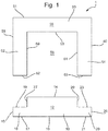
- Fig. 1 shows a vehicle mount 1 comprising a first member 10 and a second member 50.
- the first member 10 is configured to attach to a structural member (not shown in Fig. 1 ) of a vehicle.
- the second member 50 comprises first and second limbs 52, 54.
- the first and second limbs 52, 54 define a space 56 therebetween for receipt of an arm (not shown in Fig. 1 ) attachable to a component (not shown in Fig. 1 ) of a vehicle.
- the first member 10 comprises a central body portion 12.
- the central body portion 12 comprises two axially opposing end faces, a first face 14 and a second face 16.
- First and second axially opposing end surfaces 14, 16 are therefore first and second axially opposing end surfaces of the first member 10.
- the first member 10 also comprises first and second protrusions 18, 20. Each protrusion is a flanged portion of the central body portion 12 and extends from an opposing peripheral outer surface of the central body portion 12.
- the first protrusion 18 has first and second opposing surfaces 17, 19, and a side surface 15 connecting the first and second opposing surfaces 17, 19.
- the second protrusion 20 has first and second opposing surfaces 21, 23, and a side surface 25 connecting the first and second opposing surfaces 21, 23.
- the first surface 17 of the first protrusion 18 and the first surface 21 of the second protrusion 20 are continuous with the second end surface 16 of the first member 10.
- the first surfaces 17, 21 are therefore continuous with each other. Therefore the first surfaces 17 and 21 lie in the same plane, and lie in the same plane as the second end surface 16.
- the second surface 19 of the first protrusion 18 and the second surface 23 of the second protrusion 20 are connected to the first end surface 14 of the first member 10 via two side surfaces 27, 29 of the central body portion 12 of the first member 10. That is, the second surface 19 of the first protrusion 18 is connected to the first end surface 14 of the first member 10 via a first side surface 27 of the central body portion 12, and the second surface 21 of the second protrusion 20 is connected to the first end surface 14 of the first member 10 via a second side surface 29 of the central body portion 12.
- the surfaces 15, 25 are on either side of the central body portion 12 and face away from each other.
- the surfaces 27, 29 are on either side of the central body portion 12 and face away from each other.
- the first member comprises a substantially T-shaped cross section.
- the surfaces 17, 15, 19, and 27 and protrusion 18 may be regarded as a first side section of the first member 10, and the surfaces 21, 23, 25, and 29 and protrusion 20 may be regarded as a second side section of the first member 10.
- the part of the central body portion 12 between the two side sections may be regarded as a raised central body portion 12.
- the second member 50 comprises a distal outer surface 51 and a distal inner surface 53.
- Distal outer and inner surfaces 51, 53 are opposing axial end surfaces, or faces, of a body portion 55 of the second member 50.
- the first and second limbs 52, 54 of the second member 50 protrude away from the body portion 55.
- Each limb 52, 54 protrudes away from an opposing terminal end of the body portion 55.
- the first limb 52 comprises a first limb outer surface 58 and a first limb inner surface 59.
- the second limb 54 comprises a second limb outer surface 60 and a second limb inner surface 61.
- the first limb inner and outer surfaces 58, 59 are connected to each other via a first limb end surface 62.
- the second limb inner and outer surfaces 60, 61 are connected to each other via a second limb end surface 63. Therefore, the first limb 52 is defined by first limb outer surface 58, first limb end surface 62, and first limb inner surface 59; and the second limb 54 is defined by second limb outer surface 60, second limb end surface 63, and second limb inner surface 61.
- the first limb 52 is connected to the second surface body potion 55 at an end opposite to the first limb end surface 62.
- the second limb 54 is connected to the second surface body portion 55 at an end opposite to the second limb end surface 63.
- the first and second inner limb surfaces 59, 61 face each other.
- the first and second outer limb surfaces 58, 60 face away from each other. In this way, the second member comprises a substantially U-shaped cross section.
- the distal outer surface 51 of the second member 50 is at right angles with respect to the outer limb surfaces 58, 60.
- Outer limb surfaces 58, 60 are at right angles with respect to end surface 61, 63, respectively, which are at right angles to inner limb surfaces 59, 61, respectively, which are at right angles to the distal inner surface 53. In other examples, however these angles may be approximate, or different.
- the space 56 between the first and second limbs 52, 54 defines an opening for receipt of an arm (not shown), the arm being attachable to a component, e.g. of a vehicle.
- the space 56 between the first and second limbs 52, 54 is delimited by the first and second inner limb surfaces 59, 61, and the distal inner surface 53.
- a dimension of this opening is equal to the distance between the first and second limbs 52, 54 of the second member 50.
- At least part of the space 56 is for receipt of at least part of the first member 10.
- at least part of the space 56 is for receipt of the central body portion 12 of the first member 10.
- at least part of the space 56 may be for receipt of the part of the central body portion 12 delimited by the first end surface 14, and side central body portion surfaces 27, 29.
- the distance between the two inner limb surfaces 59, 61 may be approximately equal to the distance between the two central body portion side surfaces 27, 29, enabling a substantial friction fit between the central body portion 12 and the two limbs 59, 61 (thereby enabling a substantial friction fit between the two members 10, 50).
- Fig. 2 shows the vehicle mount 1 when the first member 10 is attached to the second member 50. It will be appreciated that, when the first member 10 is attached to the second member 50, the first and second limbs 52, 54 of the second member 50 define an opening 65 for receipt of an arm (not shown) attachable to a component of a vehicle.
- the space (56, see Fig. 1 ) between the first and second limbs 52, 54 defines the opening 65.
- the opening 65 is defined by the first and second inner limb surfaces 59, 61, the distal inner surface 53 of the second member 50 and the first end surface 14 of the central body portion 12.
- the first limb outer surface 58 may be substantially flush (e.g. form a contiguous and/or continuous and/or level surface) with (and/or have the same lateral extent as) side surface 15, such that the surfaces 58, 15 may together define an outer extent of the vehicle mount 1 on one side.
- the second limb outer surface 60 may be substantially flush (e.g. form a contiguous and/or continuous and/or level surface) with (and/or have the same lateral extent as) side surface 25, such that surfaces 60, 25 may together define an outer extent of the vehicle mount 1 on one side.
- the first and second limb outer surfaces 58, 60 may define outer extremities of the vehicle mount 1.
- a (e.g. lateral) dimension (e.g. a thickness) of the first limb 52 may equal a (e.g. lateral) dimension (e.g. a length) of the first protrusion 18, such that the first protrusion 18 may extend laterally the same distance from the central body portion 12 and/or first side surface 27 as the thickness of the first limb 52.
- the outer surface 58 of the first limb 52 may form a common outer surface with side surface 15 of the first member 10.
- the inner surface 59 may abut first side surface 27 of the central body portion 12 of the first member 10.
- a (e.g. lateral) dimension (e.g. a thickness) of the second limb 54 may equal a (e.g. lateral) dimension (e.g. a length) of the second protrusion 20, such that the second protrusion 20 may extend laterally the same distance from the central body portion 12 and/or second side surface 29 as the thickness of the second limb 54.
- the outer surface 60 of the second limb 54 may form a common outer surface with side surface 25 of the first member 10.
- the inner surface 61 may abut second side surface 29 of the central body portion 12 of first member 10.
- a lateral dimension of the central body portion 12 e.g. between first and second side surfaces 27, 29
- the first member 10 may be attached to a structural member of a vehicle, and the second member 50 may be attached to the first member 10, as described below.
- Figure 2 One example way of attaching the first member 10, and therefore the vehicle mount 1, to a structural member of a vehicle is shown in Figure 2 .
- the second member 50 may be attached to the first member 10 by means of linearly inserting and/or translating the second member 50 on to the first member 10 (e.g. in a direction substantially parallel to the first and second limbs 52, 54 and/or substantially perpendicular to the vehicle structural member).
- the first side surface 27 abuts the first limb inner surface 59 and the second side surface 29 abuts the second limb inner surface 61
- the first limb end surface 62 abuts the second surface 19 of the first protrusion 18
- the second limb end surface 63 abuts the second surface 23 of the second protrusion 20. Attachment between the first and second members 10, 50 may therefore be via engagement between at least one pair of these respective surfaces.
- the second member 50 may not be linearly insertable or translatable, such that linear insertion or translation may not be suitable for adjoining the second member 50 the first member 10. Rotational motion of the second member may be necessary.
- the second member 50 in some examples may be rotatably insertable.
- At least one fastener may be used.
- a first fastener A extends through the second member 50 and into the first member.
- First fastener A extends into the first limb 52 via the first limb outer surface 58, through the first limb 52, out of the first limb 52 via the first limb inner surface 59, and into the central body portion 12 of the first member 10 via the first side surface 27.
- a second fastener B extends through the second member 50 and into the first member.
- Second fastener B extends into the second limb 54 via the second limb outer surface 60, through the second limb 54, out of the first limb 54 via the second limb inner surface 61, and into the central body portion 12 of the first member 10 via the second side surface 29. In this way at least one of the fasteners A and B will fix the relative position of the first and second members 10, 50.
- the fasteners A and B may each extend laterally through the second member 50 and into the first member 10.
- the fasteners may each extend into the second member 50 from an opposing side of the second member 50.
- Each of the first and second protrusions 18, 20 may comprise an opening (not shown) for receipt of fasteners C, D.
- the opening may extend through the thickness of the first and second protrusions 18, 20 (e.g. from the first limb end surface 19 through to the end surface 16, and/or from the second limb end surface 23 through to the end surface 16).
- the two fasteners C, D and/or two further fasteners A, B may each have a head and a shaft, the head being of larger dimensions than the shaft, and the shaft having a screw thread about its circumferential surface.
- the shaft may have a central longitudinal axis which it shares with the head.
- the two fasteners C, D may extend from one side of the central body portion 12 to outside the central body portion 12.
- fastener C and/or D may be substantially parallel with the first limb 52 and/or first side surface 27 and/or end surface 15 in an assembled configuration.
- the opening through the first and second portions may not be of constant dimensions (e.g. such that a fastener having a head and a shaft/body may be flush or alternatively housed within a recess of the respective protrusion 18, 20).
- Each fastener C, D may thus not protrude from the respective end surface 19, 23 on the assembled/installed configuration.
- a flush surface 19, 23 is thus maintained, suitable for receipt and/or abutment of first and second limb end surfaces 62, 63.
- each fastener C, D may be countersunk within and/or flush with first and second end surfaces 19, 23.
- the first member 10 is therefore attached to the vehicle mount 1, the first end surface 15 and second end surface 25 forming outer extremities of the first member 10.
- the first member 10 may be attached to a structural member of a vehicle, and the second member 50 may be attached to the first member 10, as described above with reference to Figure 2 .
- One example way of attaching the first member 10, and therefore the vehicle mount 1, to a structural member of a vehicle is shown in Figure 2 .
- Two fasteners C and D extend from inside the central body portion 12 outside the central body portion 12. In one example, the two fasteners C, D may extend out of the central body portion 12, and therefore outside of the first member 10, via the second end surface 16 (e.g. a central portion thereof).
- the two fasteners C, D may extend out of the central body portion 12, and therefore outside of the first member 10, via the first surface 17 of the first protrusion 18 and the first surface 21 of the second protrusion 20, respectively. Therefore, in one example, two fasteners C, D may extend out of the first member 10 at opposing distal ends.
- two holes each corresponding to one of the fasteners C, D, may be provided in the structural member.
- the part of the fasteners C, D protruding out of the first member 10 may each be received in a respective hole of the structural member.
- a nut for example, may then be placed along the fastener to prevent disconnection between the structural member and the vehicle mount 1.
- at least one of the fasteners C, D may be a threaded fastener, and a threaded nut may be used to secure the structural member against the first member 10.
- the second member 50 comprises a space 56 between the first and second limbs 52, 54.
- This space defines an opening 65 for receipt of another article, e.g. an arm.
- a first dimension of the opening 65 is equal to the distance between the first and second limbs 52, 54.
- a length d of the opening 65 is equal to the distance d between the first and second limbs 52, 54 of the second member 50, e.g. the distance between the first and second limb inner surfaces 59, 61.
- a second dimension h of the opening 65 (this may be termed the height of the opening 65) is equal to the distance between the distal inner surface 53 of the second member 50 and the first end surface 14 of the first member 10.
- two dimensions of the opening 65 are defined by the distance between the first and second limbs, 52, 54, and the distance between the distal inner surface 53 and the first end surface 14, respectively. Therefore, in this example, the opening 65 may be a closed opening delimited, or defined, by the distal inner surface 53, the first limb inner surface 59, the first end surface 14 of the first member 10, and the second limb inner surface 61.
- the first and second members may be complementarily designed.
- the first member 10 may comprise a substantially T-shaped cross section and the second member 50 may comprise a U-shaped cross section.
- the body of the T may be defined by the central body portion 12 and the limbs of the 'T' may be defined by the two protrusions (or flanges, or side sections) 18, 20.
- the limbs of the 'U' may be defined by the first and second limbs 52, 54.
- the two members may be dimensioned such that they may be attached together via a friction fit.
- a dimension of the first end surface 14 of the first member 10 may be equal to the distance d between the first and second inner limb surfaces 59, 61.
- the mechanism of attachment may be different.
- attachment between the first and second members 10, 50 may be via abutment, e.g. abutment between the end surfaces 62, 63 (of the first and second limbs 52, 54, respectively), and the second surfaces 19, 23 (of the first and second protrusions 18, 20, respectively). In this way, an attachment may be a 'loose' connection.
- the opening 65 defines a potential travel distance for an armature received therein.
- Fig. 3 shows the vehicle mount 1, with the first and second members 10, 50 attached as shown in Fig. 2 , with an arm 99 attached. It will be appreciated that the arm 99 is received in the opening 65 of the vehicle mount 1.
- the vehicle mount 1 is attached to a structural member 98 of a vehicle (not shown in Fig. 3 ).
- the vehicle mount 1 is attached to the structural member 98 via fasteners C and D that extend through and out of the first member 10.
- the arm 99 is attached to the first surface 14 of the first member 10.
- the arm 99 may be attached to a top surface of the first member 10.
- the structural member 98 may be, for example, a vehicle side rail.
- the arm 99 may be attached to an engine, for example an ICE, positioned near the middle of the vehicle.
- the vehicle may travel forwards or backwards, in the direction of travel indicated in Fig. 3 by the arrow X. Therefore, during instances of heavy acceleration or deceleration, the arm 99 itself may be subject to a force in the direction of arrow X.
- the dimension d of the opening 65 may therefore be regarded as a possible travel distance for the arm 99, or any mounting element attached thereto (see Fig. 4 ). In this way, in the event of sudden or heavy acceleration or deceleration, the arm 99 is constrained to move within the opening 65.
- the complementary configuration of the first and second members 10, 50 allows the dimension d of the opening to be maximised without significantly increasing the overall footprint of the vehicle mount 1.
- the difference between the dimension d of the opening 65 differs from the length l of the vehicle mount 1 only by the lengths of the first and second limbs 52, 54 of the second member 50.
- the sudden force acting on the arm 99 may cause it to move within the opening 65. Maximising the opening in this way may reduce the force that the arm 99 applies to another component, e.g. one of the limbs 52, 54, when it moves. Thus, in turn, maximising the opening dimension d may better distribute crash forces.
- An offset bolt pattern may be used to attach the first member 10 to the structural member 98.
- each of the fasteners C and D may be part of a group of fasteners, with each fastener in the group being offset from one another.
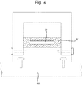
- Fig. 4 shows the vehicle mount 1, as depicted in Fig. 2 , but in Fig. 4 the structural member 98 is also shown.
- the arm 99 is received in the space 56 of the vehicle mount 1, however the arm 99 is received in a resiliently deformable element 97, and the resiliently deformable element 97 is received in the space 65.
- the dimension d of the opening constrains the space within which the arm 99 and resiliently deformable element 97 are able to move.
- a force applied to the arm 99 may cause it to move within the resiliently deformable element 97, which is constrained to move within the opening 65.
- Fig. 5 shows an example vehicle mount 100.
- Fig. 5 shows a vehicle mount 100 comprising a first member 110 and a second member 150.
- the first member 110 is configured to attach to a structural member (not shown in Fig. 5 ) of a vehicle.
- the second member 150 comprises first and second limbs 152, 154.
- the first and second limbs 152, 154 define a space 156 therebetween for receipt of an arm (not shown in Fig. 5 ) attachable to a component (not shown in Fig. 5 ) of a vehicle.
- the first member 110 comprises a central body portion 12, first and second opposing end surfaces 114, 116, and first and second protrusions, or flanged portions 118, 120.
- the example of Fig. 5 differs from the example of Figs. 1-4 in that the first member 110 comprises a third protrusion 130.
- the third protrusion 130 comprises first and second opposing surfaces 131, 132, and a side surface 133 connecting the first and second opposing surfaces 131, 132.
- the first surface 131 of the third protrusion 130 is continuous with the first end surface 114 of the first member 110.
- the first surface 131 of the third protrusion 130 is in the same plane as the end surface 114 of the first member 110.
- the second side surface 129 of the first member 110 is in between the second and third protrusions. Specifically, the second surface 123 of the second protrusion 120 is connected to the second side surface 129 of the first member 110, and the second side surface 129 is connected to the second surface 132 of the third protrusion 130.
- members 110 and 150 are complementarily designed.
- the second limb 154 of the second member 154 comprises a first flange 170.
- the first flange 170 is disposed at a distal end of the second limb 154.
- the first flange 170 comprises first and second opposing surfaces 171, 172, and an end surface 173.
- the end surface 173 connects the first and second opposing surfaces 171, 172.
- the outer surface 160 of the second limb 154 (rather than connecting to the limb end surface as in Figs. 1-4 ), in Fig. 5 , connects to, or joins, the second flange surface 172.
- the inner surface 161 of the second limb 154 (rather than connecting to a limb end surface as in Fig. 1-4 ), in Fig. 5 , connects to the first flange surface 171.
- the first flange surface 171, and the second limb inner surface 161 are at right angles
- the first flange surface is at right angles to the flange side surface 173
- the flange side surface 173 is at right angles to the second flange surface 172
- the second flange surface 172 is at right angles to the second limb outer surface 160.
- the two flanges, 130 and 170 through complementary engagement, may facilitate attachment between the two members 110 and 150, and attachment between the two members 110, 150 may be via the engagement between the two flanges.
- at least one of the flanges 130, 170 may be a protrusion and the other may be considered an opening for receipt of the protrusion.
- An optional fastener E may be used to further secure the two members 110, 150 together.
- the distance between the two limbs 152, 154, defines a space 156 therebetween.
- This space 156 defines an opening 165 for receipt of an arm (not shown).
- the space 165 is defined by the distal inner surface 153 of the second member 150, the two limb inner surfaces, 159, 161, and the first end surface 114 of the first member 110.
- a dimension of the opening 165 is equal to the distance between the two limb inner surfaces 159, 161.
- first member 110 and the second member 150 may be attached to one another via the hook-like attachment between the two flanges 130, 170.
- the second member 150 may hook over and onto the first member 110 via the two flanges 130, 170.
- Fig. 6 shows another example vehicle mount 200.
- the vehicle mount 200 of Fig. 6 is identical to the vehicle mount shown in Fig. 5 but for the following features.
- the second member 250 in the vehicle mount of Fig. 6 example comprises a second limb 254.
- the second limb 254 comprises a first flange 270 and a second flange 280.
- the second flange 280 is an extension, and/or protrusion, of the first flange 270.
- the first flange 270 comprises a protrusion that is the second flange 280.
- the first flange 270 has first and second surfaces 271, 272, as per Fig. 5 .
- the first flange 270 has a side surface 273 that connects, or joins, the first and second surfaces 271, 272.
- the second flange 280 has first and second opposing surfaces 281, 283 and an end surface 282.
- the side surface 273 of the first flange 270 is continuous with the first surface 281 of the second flange 280.
- the side surface 273 is in the same plane as the first surface 281.
- the first surface 281 of the second flange 270 is connected to the end surface 282 and the end surface 282 is connected to the second surface 283, which is connected to the second surface 272 of the first flange 270.
- First surface 281 is at right angles to the end surface 282
- the end surface 282 is at right angles to the second surface 283,
- the second surface 283 is at right angles to the second surface 272.
- surfaces 271, 272, and 282 are parallel with one another; and surfaces 273, 281, and 283 are parallel with one another.
- vehicle mount 200 of the Fig. 6 example may be assembled by sliding the first and second members 210, 250 into engagement with one another.
- Fig. 7 shows an example second member 350.
- the second member 350 comprises two opposing body portions 355, 390, and two opposing limbs 352, 354.
- the four elements 355, 390, 352, 354 give the second member 350 a frame-like cross section.
- the second member 350 may be attached to a (not-shown) first member, via at least one fastener extending into and through the second body portion 390 and into the first member.
- the second member 350 of the Fig. 7 example comprises first and second limbs 352, 354 which define a space therebetween 356. This space defines an opening 365 for receipt of an arm which, in this example, is attachable to the second body portion 390 of the second member 350.
- the second member 350 is attached to a first member to form the vehicle mount, the arm may be attached to the second member and not to the first member (as in the examples of Figs. 1-6 ).
- At least one of the first and second members may comprise a hinge attachment to hingedly attach the two members together.
- the present invention may therefore be advantageous for a number of reasons.
- the vehicle mount of the present invention may have the same external dimensions (e.g. same or similar width) as existing vehicle mounts.
- the at least one first set of fasteners C, D attaching the first member of the second member may be insertable and/or receivable within existing openings of the structural member (e.g. the openings within the first member 10 are of the same separation and dimension as the openings of the vehicle structural mount).
- the vehicle mount of the present invention allows for a greater mount travel span, along with its associated advantages. As such, the present invention allows for a greater mount travel span, without increasing the maximum width of the vehicle mount compared with existing vehicle mounts, and whilst having fasteners insertable within the same openings of vehicle structural members.
- the vehicle mount of the present invention may thus be retrofitted to existing vehicles and/or existing vehicle side rails.
- Examples of the invention may be provided according to any one of the following numbered statements.
Landscapes
- Engineering & Computer Science (AREA)
- Chemical & Material Sciences (AREA)
- Combustion & Propulsion (AREA)
- Transportation (AREA)
- Mechanical Engineering (AREA)
- Body Structure For Vehicles (AREA)
Abstract
Description
- The present disclosure relates to a vehicle mount for attachment to a structural member of a vehicle. In one example, the present disclosure relates to a vehicle mount for attachment to a side rail of a vehicle, for example a motor vehicle.
- As structural members of some example vehicles become thinner, for example due to factors such as tyre clearance envelopes and powertrains growing in size (e.g. due to regulations and/or customer demands), the size of attachment portions of some vehicle mounts may increase so that they can attach to the thinner structural members. Narrower structural members, such as side rails of vehicles, may mean that vehicle mounts need to be designed differently to facilitate their attachment to such a narrower structural member.
- The present disclosure generally relates to a vehicle mount for attachment to a structural member of a vehicle that does not reduce the space in the vehicle mount for receipt of an arm, e.g. an arm attachable to a component of a vehicle, such as an internal combustion engine (ICE).
- In one example there is provided a vehicle mount comprising a first member configured to attach to a structural member of a vehicle and a second member comprising first and second limbs, the first and second limbs defining a space therebetween for receipt of an arm attachable to a component of the vehicle. The second member is configured to attach to the first member such that, when the second member is attached to the first member, the space between the first and second limbs defines an opening for receipt of an arm attachable to the component of the vehicle, with a dimension of the opening being equal to the distance between the first and second limbs.
- The first member may comprise a central body portion and at least one flange protruding away from the central body portion. Each flange may comprise a surface that is continuous with, and contained in the same plane as, a surface of the central body portion. The second member may comprise a portion to engage the flange of the first member such that, when the second member is attached to the first member, engagement between the flanged portion and the second member may fix the position of the second member relative to the first member.
- The second member may comprise first and second limbs protruding away from a central body portion of the second member. The central body portion may comprise a raised end surface, and wherein, when the second member is attached to the first member, the raised end surface may be received in the second member between the two limbs.
- The first member may comprise a central body portion and at least one flange protruding away from the central body portion, and the central body portion may comprise a raised end surface, and wherein, when the second member is attached to the first member, the raised end surface may be received in the second member between the two limbs, and wherein the second member may comprise a hole for receipt of at least one fastener, such that, when the second member is attached to the first member, the at least one fastener may be configured to be received in the hole such that the at least one fastener extends through one of the two limbs of the second member and into the central body portion of the first member. A fastener may laterally fasten the second member to the first member.
- The second member may comprise a body portion comprising an inner surface, and two limbs each extending away from the body portion at an end of the body portion, each limb may comprise an inner surface. The inner surfaces of the limbs may face each other, and the space between the limbs may be defined by the space between the two limb inner surfaces and the inner surface of the second member. The opening may be defined by the inner surface of the second member, the inner limb surfaces, and an end face of the first member.
- The first member may comprise a central body portion , which may comprise first and second axially opposing end faces, and wherein the second member may comprise a body portion comprising an inner surface, and two limbs each extending away from the body portion at an end of the body portion, each limb comprising an inner surface, wherein the inner surfaces of the limbs may face each other, and wherein the space between the limbs may be defined by the space between the two limb inner surfaces and the inner surface of the second member, and wherein the opening may be defined by the inner surface of the second member, the inner limb surfaces, and the first end face of the central body portion, wherein the second end face of the central body portion may comprise a hole for receipt of at least one fastener to attach the first member to the structural member of the vehicle.
- The second member may comprise two limbs, and a flange extending approximately at right angles from one of the two limbs.
- The first member may comprise a flange extending away from a central body portion of the first member, and wherein, when the second member is attached to the first member, the flange of the first member may be engaged with the flange of the second member.
- At least one of the first and second members may comprise a hinge, and wherein one of the first and second members may be configured to be attached to the other of the first and second members at the hinge, thereby permitting hinged movement of the first and second members relative to each other.
- The second member may be slidably attachable to the first member.
- The structural member of the vehicle may be at least one rail of the vehicle.
- The component of the vehicle may be at least one of: a component of a drive train of the vehicle, a component of an engine of the vehicle, and a component of a cab of the vehicle.
- The first member may be attachable to the structural member by means of at least one first fastener. The at least one first fastener may be insertable in the first member such that, upon assembly, the at least one first fastener may be substantially perpendicular to a surface of the structural member and inserted within the structural member. The at least one first fastener may directly fasten and/or attach only the first member to the structural member (e.g. not the second member).
- The second member may be attachable to the first member such that the first and second limbs of the second member abut the first member. The second member may be attachable to the first member by means of at least one second fastener. The at least one second fastener may be insertable within the second member (e.g. through at least one of the limbs of the second member) such that the at least one second fastener passes through the second member and into the first member. The at least one second fastener may not pass into (e.g. attach to) the structural member (e.g. the at least one second fastener may attach the second member to the first member only and/or the at least one second fastener may not attach the second member to the structural member). The at least one second fastener may be disposed substantially parallel with the structural member and/or substantially perpendicular to the at least one first fastener. Upon attachment of the second member to the first member, the second member may conceal and/or obscure and/or obstruct the at least one first fastener, such that only the at least one second fastener may be substantially visible and/or accessible from the exterior of the vehicle mount. In an assembled configuration, the at least one first fastener and the at least one second fastener may substantially perpendicular to one another.
- The external lateral dimensions of the vehicle mount may be defined by the exterior of the first and second limbs of the second member (e.g. the first and second limbs may define outer extremities or limits or boundaries of the vehicle mount). No other part or component of the vehicle mount (optionally except for the at least one second fastener) may extend further laterally than the first and second limbs of the second member.
- The mount travel span may be (e.g. substantially) equal to the outer (lateral) dimensions (e.g. a maximum width) of the vehicle mount minus the width of each of the first and second limbs.
-
Fig. 1 shows avehicle mount 1 comprising afirst member 10 and asecond member 50. Thefirst member 10 is configured to attach to a structural member (not shown inFig. 1 ) of a vehicle. Thesecond member 50 comprises first andsecond limbs second limbs space 56 therebetween for receipt of an arm (not shown inFig. 1 ) attachable to a component (not shown inFig. 1 ) of a vehicle. - The
first member 10 comprises acentral body portion 12. Thecentral body portion 12 comprises two axially opposing end faces, afirst face 14 and asecond face 16. First and second axially opposingend surfaces first member 10. Thefirst member 10 also comprises first andsecond protrusions central body portion 12 and extends from an opposing peripheral outer surface of thecentral body portion 12. - For example, as shown in
Fig. 1 , thefirst protrusion 18 has first and secondopposing surfaces side surface 15 connecting the first and secondopposing surfaces second protrusion 20 has first and second opposingsurfaces side surface 25 connecting the first and secondopposing surfaces first surface 17 of thefirst protrusion 18 and thefirst surface 21 of thesecond protrusion 20 are continuous with thesecond end surface 16 of thefirst member 10. Thefirst surfaces first surfaces second end surface 16. Thesecond surface 19 of thefirst protrusion 18 and thesecond surface 23 of thesecond protrusion 20 are connected to thefirst end surface 14 of thefirst member 10 via twoside surfaces central body portion 12 of thefirst member 10. That is, thesecond surface 19 of thefirst protrusion 18 is connected to thefirst end surface 14 of thefirst member 10 via afirst side surface 27 of thecentral body portion 12, and thesecond surface 21 of thesecond protrusion 20 is connected to thefirst end surface 14 of thefirst member 10 via asecond side surface 29 of thecentral body portion 12. Thesurfaces central body portion 12 and face away from each other. Thesurfaces central body portion 12 and face away from each other. In this way, the first member comprises a substantially T-shaped cross section. - Collectively, the
surfaces protrusion 18 may be regarded as a first side section of thefirst member 10, and thesurfaces protrusion 20 may be regarded as a second side section of thefirst member 10. The part of thecentral body portion 12 between the two side sections may be regarded as a raisedcentral body portion 12. - As also shown in
Fig. 1 , thesecond member 50 comprises a distalouter surface 51 and a distalinner surface 53. Distal outer andinner surfaces body portion 55 of thesecond member 50. The first andsecond limbs second member 50 protrude away from thebody portion 55. Eachlimb body portion 55. - The
first limb 52 comprises a first limbouter surface 58 and a first limbinner surface 59. Thesecond limb 54 comprises a second limbouter surface 60 and a second limbinner surface 61. The first limb inner andouter surfaces limb end surface 62. The second limb inner andouter surfaces limb end surface 63. Therefore, thefirst limb 52 is defined by first limbouter surface 58, firstlimb end surface 62, and first limbinner surface 59; and thesecond limb 54 is defined by second limbouter surface 60, secondlimb end surface 63, and second limbinner surface 61. Thefirst limb 52 is connected to the secondsurface body potion 55 at an end opposite to the firstlimb end surface 62. Thesecond limb 54 is connected to the secondsurface body portion 55 at an end opposite to the secondlimb end surface 63. The first and second inner limb surfaces 59, 61 face each other. The first and second outer limb surfaces 58, 60 face away from each other. In this way, the second member comprises a substantially U-shaped cross section. - As shown in
Fig. 1 , the distalouter surface 51 of thesecond member 50 is at right angles with respect to the outer limb surfaces 58, 60. Outer limb surfaces 58, 60 are at right angles with respect to endsurface inner surface 53. In other examples, however these angles may be approximate, or different. - As will be explained in further detail below, when the
first member 10 is attached to thesecond member 50, thespace 56 between the first andsecond limbs space 56 between the first andsecond limbs inner surface 53. As will be appreciated fromFig. 1 , a dimension of this opening is equal to the distance between the first andsecond limbs second member 50. - As will also be appreciated from
Fig. 1 , at least part of thespace 56 is for receipt of at least part of thefirst member 10. Specifically, at least part of thespace 56 is for receipt of thecentral body portion 12 of thefirst member 10. For example, at least part of thespace 56 may be for receipt of the part of thecentral body portion 12 delimited by thefirst end surface 14, and side central body portion surfaces 27, 29. In this example, the distance between the two inner limb surfaces 59, 61, may be approximately equal to the distance between the two central body portion side surfaces 27, 29, enabling a substantial friction fit between thecentral body portion 12 and the twolimbs 59, 61 (thereby enabling a substantial friction fit between the twomembers 10, 50). -
Fig. 2 shows thevehicle mount 1 when thefirst member 10 is attached to thesecond member 50. It will be appreciated that, when thefirst member 10 is attached to thesecond member 50, the first andsecond limbs second member 50 define anopening 65 for receipt of an arm (not shown) attachable to a component of a vehicle. The space (56, seeFig. 1 ) between the first andsecond limbs opening 65. Theopening 65 is defined by the first and second inner limb surfaces 59, 61, the distalinner surface 53 of thesecond member 50 and thefirst end surface 14 of thecentral body portion 12. - In an assembled configuration, the first limb
outer surface 58 may be substantially flush (e.g. form a contiguous and/or continuous and/or level surface) with (and/or have the same lateral extent as)side surface 15, such that thesurfaces vehicle mount 1 on one side. - Additionally or alternatively, in an assembled configuration, the second limb
outer surface 60 may be substantially flush (e.g. form a contiguous and/or continuous and/or level surface) with (and/or have the same lateral extent as)side surface 25, such thatsurfaces vehicle mount 1 on one side. In this manner, the first and second limbouter surfaces vehicle mount 1. - As shown in
Figures 1 and2 , a (e.g. lateral) dimension (e.g. a thickness) of thefirst limb 52 may equal a (e.g. lateral) dimension (e.g. a length) of thefirst protrusion 18, such that thefirst protrusion 18 may extend laterally the same distance from thecentral body portion 12 and/orfirst side surface 27 as the thickness of thefirst limb 52. As such, on one (e.g. an outer) side offirst limb 52, theouter surface 58 of thefirst limb 52 may form a common outer surface withside surface 15 of thefirst member 10. Additionally or alternatively, on another (e.g. an inner) side offirst limb 52, theinner surface 59 may abutfirst side surface 27 of thecentral body portion 12 of thefirst member 10. - In a similar manner, a (e.g. lateral) dimension (e.g. a thickness) of the
second limb 54 may equal a (e.g. lateral) dimension (e.g. a length) of thesecond protrusion 20, such that thesecond protrusion 20 may extend laterally the same distance from thecentral body portion 12 and/orsecond side surface 29 as the thickness of thesecond limb 54. As such, on one (e.g. an outer) side ofsecond limb 54, theouter surface 60 of thesecond limb 54 may form a common outer surface withside surface 25 of thefirst member 10. Additionally or alternatively, on another (e.g. an inner) side ofsecond limb 54, theinner surface 61 may abutsecond side surface 29 of thecentral body portion 12 offirst member 10. As such, a lateral dimension of the central body portion 12 (e.g. between first and second side surfaces 27, 29) may be substantially equal to an inner dimension defined between the first andsecond limbs - To attach the
vehicle mount 1 to a structural member (not shown) of a vehicle, thefirst member 10 may be attached to a structural member of a vehicle, and thesecond member 50 may be attached to thefirst member 10, as described below. One example way of attaching thefirst member 10, and therefore thevehicle mount 1, to a structural member of a vehicle is shown inFigure 2 . - As shown in
Figures 1 and2 , thesecond member 50 may be attached to thefirst member 10 by means of linearly inserting and/or translating thesecond member 50 on to the first member 10 (e.g. in a direction substantially parallel to the first andsecond limbs - When the
second member 50 is attached to thefirst member 10, thefirst side surface 27 abuts the first limbinner surface 59 and thesecond side surface 29 abuts the second limbinner surface 61, the firstlimb end surface 62 abuts thesecond surface 19 of thefirst protrusion 18, and the secondlimb end surface 63 abuts thesecond surface 23 of thesecond protrusion 20. Attachment between the first andsecond members - It will be noted in other embodiments (e.g. those of
Figures 5 and6 ) thesecond member 50 may not be linearly insertable or translatable, such that linear insertion or translation may not be suitable for adjoining thesecond member 50 thefirst member 10. Rotational motion of the second member may be necessary. In other words, thesecond member 50 in some examples may be rotatably insertable. - In order to fix the position of the first and
second members Figure 2 , a first fastener A extends through thesecond member 50 and into the first member. First fastener A extends into thefirst limb 52 via the first limbouter surface 58, through thefirst limb 52, out of thefirst limb 52 via the first limbinner surface 59, and into thecentral body portion 12 of thefirst member 10 via thefirst side surface 27. Similarly, a second fastener B extends through thesecond member 50 and into the first member. Second fastener B extends into thesecond limb 54 via the second limbouter surface 60, through thesecond limb 54, out of thefirst limb 54 via the second limbinner surface 61, and into thecentral body portion 12 of thefirst member 10 via thesecond side surface 29. In this way at least one of the fasteners A and B will fix the relative position of the first andsecond members second member 50 and into thefirst member 10. The fasteners may each extend into thesecond member 50 from an opposing side of thesecond member 50. - Each of the first and
second protrusions second protrusions 18, 20 (e.g. from the firstlimb end surface 19 through to theend surface 16, and/or from the secondlimb end surface 23 through to the end surface 16).
The two fasteners C, D and/or two further fasteners A, B (described below) may each have a head and a shaft, the head being of larger dimensions than the shaft, and the shaft having a screw thread about its circumferential surface. The shaft may have a central longitudinal axis which it shares with the head. The two fasteners C, D may extend from one side of thecentral body portion 12 to outside thecentral body portion 12. As such, fastener C and/or D (in particular, the central axis) may be substantially parallel with thefirst limb 52 and/orfirst side surface 27 and/or endsurface 15 in an assembled configuration. The opening through the first and second portions may not be of constant dimensions (e.g. such that a fastener having a head and a shaft/body may be flush or alternatively housed within a recess of therespective protrusion 18, 20). Each fastener C, D may thus not protrude from therespective end surface flush surface first member 10 is therefore attached to thevehicle mount 1, thefirst end surface 15 andsecond end surface 25 forming outer extremities of thefirst member 10. - To attach the
vehicle mount 1 to a structural member (not shown) of a vehicle, thefirst member 10 may be attached to a structural member of a vehicle, and thesecond member 50 may be attached to thefirst member 10, as described above with reference toFigure 2 . One example way of attaching thefirst member 10, and therefore thevehicle mount 1, to a structural member of a vehicle is shown inFigure 2 . Two fasteners C and D, extend from inside thecentral body portion 12 outside thecentral body portion 12. In one example, the two fasteners C, D may extend out of thecentral body portion 12, and therefore outside of thefirst member 10, via the second end surface 16 (e.g. a central portion thereof). In another example, the two fasteners C, D may extend out of thecentral body portion 12, and therefore outside of thefirst member 10, via thefirst surface 17 of thefirst protrusion 18 and thefirst surface 21 of thesecond protrusion 20, respectively. Therefore, in one example, two fasteners C, D may extend out of thefirst member 10 at opposing distal ends. - To connect, or attach, the
vehicle mount 1 to a structural member of a vehicle, two holes, each corresponding to one of the fasteners C, D, may be provided in the structural member. The part of the fasteners C, D protruding out of thefirst member 10 may each be received in a respective hole of the structural member. A nut, for example, may then be placed along the fastener to prevent disconnection between the structural member and thevehicle mount 1. For example, at least one of the fasteners C, D, may be a threaded fastener, and a threaded nut may be used to secure the structural member against thefirst member 10. - As above, the
second member 50 comprises aspace 56 between the first andsecond limbs opening 65 for receipt of another article, e.g. an arm. A first dimension of theopening 65 is equal to the distance between the first andsecond limbs Fig. 2 , a length d of theopening 65 is equal to the distance d between the first andsecond limbs second member 50, e.g. the distance between the first and second limbinner surfaces Fig. 2 , when thesecond member 50 is attached to thefirst member 10, a second dimension h of the opening 65 (this may be termed the height of the opening 65) is equal to the distance between the distalinner surface 53 of thesecond member 50 and thefirst end surface 14 of thefirst member 10. As such, in the example ofFig. 2 , two dimensions of theopening 65 are defined by the distance between the first and second limbs, 52, 54, and the distance between the distalinner surface 53 and thefirst end surface 14, respectively. Therefore, in this example, theopening 65 may be a closed opening delimited, or defined, by the distalinner surface 53, the first limbinner surface 59, thefirst end surface 14 of thefirst member 10, and the second limbinner surface 61. - As will be appreciated, to facilitate attachment therebetween, the first and second members may be complementarily designed. For example, and as shown in
Fig. 2 , thefirst member 10 may comprise a substantially T-shaped cross section and thesecond member 50 may comprise a U-shaped cross section. The body of the T may be defined by thecentral body portion 12 and the limbs of the 'T' may be defined by the two protrusions (or flanges, or side sections) 18, 20. Similarly, the limbs of the 'U' may be defined by the first andsecond limbs first end surface 14 of thefirst member 10 may be equal to the distance d between the first and second inner limb surfaces 59, 61. In other examples, the mechanism of attachment may be different. For example, attachment between the first andsecond members second limbs second surfaces 19, 23 (of the first andsecond protrusions - The
opening 65 defines a potential travel distance for an armature received therein. -
Fig. 3 shows thevehicle mount 1, with the first andsecond members Fig. 2 , with an arm 99 attached. It will be appreciated that the arm 99 is received in theopening 65 of thevehicle mount 1. As is also shown inFig. 3 , thevehicle mount 1 is attached to astructural member 98 of a vehicle (not shown inFig. 3 ). Thevehicle mount 1 is attached to thestructural member 98 via fasteners C and D that extend through and out of thefirst member 10. As is shown inFig. 3 , the arm 99 is attached to thefirst surface 14 of thefirst member 10. The arm 99 may be attached to a top surface of thefirst member 10. - The
structural member 98 may be, for example, a vehicle side rail. The arm 99 may be attached to an engine, for example an ICE, positioned near the middle of the vehicle. In this example, the vehicle may travel forwards or backwards, in the direction of travel indicated inFig. 3 by the arrow X. Therefore, during instances of heavy acceleration or deceleration, the arm 99 itself may be subject to a force in the direction of arrow X. The dimension d of theopening 65 may therefore be regarded as a possible travel distance for the arm 99, or any mounting element attached thereto (seeFig. 4 ). In this way, in the event of sudden or heavy acceleration or deceleration, the arm 99 is constrained to move within theopening 65. - As will be appreciated, the complementary configuration of the first and
second members vehicle mount 1. For example, the difference between the dimension d of theopening 65 differs from the length l of thevehicle mount 1 only by the lengths of the first andsecond limbs second member 50. - In the event of a vehicle collision, the sudden force acting on the arm 99 may cause it to move within the
opening 65. Maximising the opening in this way may reduce the force that the arm 99 applies to another component, e.g. one of thelimbs - An offset bolt pattern may be used to attach the
first member 10 to thestructural member 98. For example, each of the fasteners C and D may be part of a group of fasteners, with each fastener in the group being offset from one another. -
Fig. 4 shows thevehicle mount 1, as depicted inFig. 2 , but inFig. 4 thestructural member 98 is also shown. In the example ofFig. 4 , the arm 99 is received in thespace 56 of thevehicle mount 1, however the arm 99 is received in a resilientlydeformable element 97, and the resilientlydeformable element 97 is received in thespace 65. As stated with reference toFig. 3 , the dimension d of the opening constrains the space within which the arm 99 and resilientlydeformable element 97 are able to move. - In this example, during or immediately following a collision, a force applied to the arm 99 may cause it to move within the resiliently
deformable element 97, which is constrained to move within theopening 65. -
Fig. 5 shows anexample vehicle mount 100. As in the example ofFigs 1-4 ,Fig. 5 shows avehicle mount 100 comprising afirst member 110 and asecond member 150. Thefirst member 110 is configured to attach to a structural member (not shown inFig. 5 ) of a vehicle. Thesecond member 150 comprises first andsecond limbs second limbs space 156 therebetween for receipt of an arm (not shown inFig. 5 ) attachable to a component (not shown inFig. 5 ) of a vehicle. - As per the example of
Figs. 1-4 , thefirst member 110 comprises acentral body portion 12, first and second opposing end surfaces 114, 116, and first and second protrusions, orflanged portions - The example of
Fig. 5 differs from the example ofFigs. 1-4 in that thefirst member 110 comprises athird protrusion 130. Thethird protrusion 130 comprises first and second opposingsurfaces side surface 133 connecting the first and second opposingsurfaces first surface 131 of thethird protrusion 130 is continuous with thefirst end surface 114 of thefirst member 110. Thefirst surface 131 of thethird protrusion 130 is in the same plane as theend surface 114 of thefirst member 110. Thesecond side surface 129 of thefirst member 110 is in between the second and third protrusions. Specifically, the second surface 123 of thesecond protrusion 120 is connected to thesecond side surface 129 of thefirst member 110, and thesecond side surface 129 is connected to thesecond surface 132 of thethird protrusion 130. - In the example of
Fig. 5 ,members second limb 154 of thesecond member 154 comprises afirst flange 170. Thefirst flange 170 is disposed at a distal end of thesecond limb 154. Thefirst flange 170 comprises first and second opposingsurfaces end surface 173. Theend surface 173 connects the first and second opposingsurfaces outer surface 160 of the second limb 154 (rather than connecting to the limb end surface as inFigs. 1-4 ), inFig. 5 , connects to, or joins, thesecond flange surface 172. Similarly, theinner surface 161 of the second limb 154 (rather than connecting to a limb end surface as inFig. 1-4 ), inFig. 5 , connects to thefirst flange surface 171. In the example ofFig. 5 , thefirst flange surface 171, and the second limbinner surface 161 are at right angles, the first flange surface is at right angles to theflange side surface 173, theflange side surface 173 is at right angles to thesecond flange surface 172, and thesecond flange surface 172 is at right angles to the second limbouter surface 160. - It will be appreciated that the two flanges, 130 and 170, through complementary engagement, may facilitate attachment between the two
members members flanges - An optional fastener E may be used to further secure the two
members - The distance between the two
limbs space 156 therebetween. Thisspace 156 defines anopening 165 for receipt of an arm (not shown). When thesecond member 150 is attached to thesecond member 110, as shown inFig. 5 , thespace 165 is defined by the distalinner surface 153 of thesecond member 150, the two limb inner surfaces, 159, 161, and thefirst end surface 114 of thefirst member 110. A dimension of theopening 165 is equal to the distance between the two limbinner surfaces - It will be appreciated, that the
first member 110 and thesecond member 150 may be attached to one another via the hook-like attachment between the twoflanges second member 150 may hook over and onto thefirst member 110 via the twoflanges -
Fig. 6 shows anotherexample vehicle mount 200. Thevehicle mount 200 ofFig. 6 is identical to the vehicle mount shown inFig. 5 but for the following features. Thesecond member 250 in the vehicle mount ofFig. 6 example comprises asecond limb 254. Thesecond limb 254 comprises afirst flange 270 and asecond flange 280. Thesecond flange 280 is an extension, and/or protrusion, of thefirst flange 270. In this way, thefirst flange 270 comprises a protrusion that is thesecond flange 280. As shown inFig. 6 , thefirst flange 270 has first andsecond surfaces Fig. 5 . Thefirst flange 270 has aside surface 273 that connects, or joins, the first andsecond surfaces second flange 280 has first and second opposingsurfaces end surface 282. Theside surface 273 of thefirst flange 270 is continuous with thefirst surface 281 of thesecond flange 280. Theside surface 273 is in the same plane as thefirst surface 281. Thefirst surface 281 of thesecond flange 270 is connected to theend surface 282 and theend surface 282 is connected to thesecond surface 283, which is connected to thesecond surface 272 of thefirst flange 270.First surface 281 is at right angles to theend surface 282 theend surface 282 is at right angles to thesecond surface 283, thesecond surface 283 is at right angles to thesecond surface 272. As will be seen fromFig. 6 , surfaces 271, 272, and 282 are parallel with one another; and surfaces 273, 281, and 283 are parallel with one another. - It will be appreciated that the
vehicle mount 200 of theFig. 6 example may be assembled by sliding the first andsecond members 210, 250 into engagement with one another. -
Fig. 7 shows an examplesecond member 350. In this example thesecond member 350 comprises two opposingbody portions 355, 390, and two opposinglimbs elements second member 350 may be attached to a (not-shown) first member, via at least one fastener extending into and through the second body portion 390 and into the first member. As with other examples, thesecond member 350 of theFig. 7 example comprises first andsecond limbs space therebetween 356. This space defines anopening 365 for receipt of an arm which, in this example, is attachable to the second body portion 390 of thesecond member 350. Thus, in theFig. 7 example, then thesecond member 350 is attached to a first member to form the vehicle mount, the arm may be attached to the second member and not to the first member (as in the examples ofFigs. 1-6 ). - Other mechanisms of attaching the first member to the second member will be appreciated. For example, at least one of the first and second members may comprise a hinge attachment to hingedly attach the two members together.
- The present invention may therefore be advantageous for a number of reasons.
- The vehicle mount of the present invention may have the same external dimensions (e.g. same or similar width) as existing vehicle mounts. Similarly, the at least one first set of fasteners C, D attaching the first member of the second member may be insertable and/or receivable within existing openings of the structural member (e.g. the openings within the
first member 10 are of the same separation and dimension as the openings of the vehicle structural mount). The vehicle mount of the present invention allows for a greater mount travel span, along with its associated advantages. As such, the present invention allows for a greater mount travel span, without increasing the maximum width of the vehicle mount compared with existing vehicle mounts, and whilst having fasteners insertable within the same openings of vehicle structural members. The vehicle mount of the present invention may thus be retrofitted to existing vehicles and/or existing vehicle side rails. - Examples of the invention may be provided according to any one of the following numbered statements.
-
Statement 1. A vehicle mount comprising:- a first member configured to attach to a structural member of a vehicle; and
- a second member comprising first and second limbs, the first and second limbs defining a space therebetween for receipt of an arm attachable to a component of the vehicle, wherein the second member is configured to attach to the first member such that, when the second member is attached to the first member, the space between the first and second limbs defines an opening for receipt of an arm attachable to the component of the vehicle, with a dimension of the opening being equal to the distance between the first and second limbs.
- Statement 2. A vehicle mount according to
statement 1, wherein the first member comprises a central body portion and at least one flange protruding away from the central body portion. - Statement 3. A vehicle mount according to statement 2, wherein each flange comprises a surface that is continuous with, and contained in the same plane as, a surface of the central body portion.
- Statement 4. A vehicle mount according to statement 2 or 3, wherein the second member comprises a portion to engage the flange of the first member such that, when the second member is attached to the first member, engagement between the flanged portion and the second member fixes the position of the second member relative to the first member.
- Statement 5. A vehicle mount according to any preceding statement, wherein the second member comprises first and second limbs protruding away from a central body portion of the second member.
- Statement 6. A vehicle mount according to statement 5 wherein the first member comprises a central body portion, wherein the central body portion comprises a raised end surface, and wherein, when the second member is attached to the first member, the raised end surface is received in the second member between the two limbs.
- Statement 7. A vehicle mount according to any preceding statement, wherein the first member comprises a central body portion and at least one flange protruding away from the central body portion, wherein the central body portion comprises a raised end surface, and wherein, when the second member is attached to the first member, the raised end surface is received in the second member between the two limbs, and wherein the second member comprises a hole for receipt of at least one fastener, such that, when the second member is attached to the first member, the at least one fastener is configured to be received in the hole such that the at least one fastener extends through one of the two limbs of the second member and into the central body portion of the first member.
- Statement 8. A vehicle mount according to any preceding statement, wherein the second member comprises a body portion comprising an inner surface, and two limbs each extending away from the body portion at an end of the body portion, each limb comprising an inner surface, wherein the inner surfaces of the limbs face each other, and wherein the space between the limbs is defined by the space between the two limb inner surfaces and the inner surface of the second member, and wherein the opening is defined by the inner surface of the second member, the inner limb surfaces, and an end face of the first member.
- Statement 9. A vehicle mount according to any preceding statement, wherein the first member comprises a central body portion comprising first and second axially opposing end faces, and wherein the second member comprises a body portion comprising an inner surface, and two limbs each extending away from the body portion at an end of the body portion, each limb comprising an inner surface, wherein the inner surfaces of the limbs face each other, and wherein the space between the limbs is defined by the space between the two limb inner surfaces and the inner surface of the second member, and wherein the opening is defined by the inner surface of the second member, the inner limb surfaces, and the first end face of the central body portion, wherein the second end face of the central body portion comprises a hole for receipt of at least one fastener to attach the first member to the structural member of the vehicle.
-
Statement 10. A vehicle mount according to any preceding statement, wherein the second member comprises two limbs, and a flange extending approximately at right angles from one of the two limbs. - Statement 11. A vehicle mount according to any preceding statement, wherein the first member comprises a flange extending away from a central body portion of the first member, and wherein, when the second member is attached to the first member, the flange of the first member is engaged with the flange of the second member.
-
Statement 12. A vehicle mount according to any preceding statement, wherein at least one of the first and second member comprises a hinge, and wherein one of the first and second members is configured to be attached to the other of the first and second members at the hinge, thereby permitting hinged movement of the first and second members relative to each other. - Statement 13. A vehicle mount according to any preceding statement, wherein the second member is slidably attachable to the first member.
-
Statement 14. A vehicle mount according to any preceding statement, wherein the structural member of the vehicle is at least one rail of the vehicle. -
Statement 15. A vehicle mount according to any preceding statement, wherein the component of the vehicle is at least one of: a component of a drive train of the vehicle, a component of an engine of the vehicle, and a component of a cab of the vehicle. -
Statement 16. The vehicle mount ofstatement 1, wherein the first member is attachable to the vehicle structural member by means of at least one first fastener. -
Statement 17. The vehicle mount ofstatement 16, wherein the second member is attachable to the first member by means of at least one second fastener. -
Statement 18. The vehicle mount ofstatement 17, wherein in an assembled configuration, the at least one second fastener does not extend into the vehicle structural member and/or attaches only to the first member. -
Statement 19. The vehicle mount ofstatement 17 orstatement 18, wherein, in an assembled configuration,:- the at least one second fastener is perpendicular to the at least one first fastener; and/or
- the at least one second fastener is parallel to the vehicle structural member.
-
Statement 20. The vehicle mount of any ofstatements 17 to 19, wherein upon attachment of the second member to the first member, the at least one first fastener is obstructed by the second member. -
Statement 21. The vehicle mount of any preceding statement, wherein a maximum dimension of the vehicle mount is defined between an outer surface of each of the first and second limbs. - Statement 22. The vehicle mount of
statement 21, wherein the outer surface of each of the first and second limbs is level with a side surface of each flange of the first member.
Claims (15)
- A vehicle mount comprising:a first member configured to attach to a structural member of a vehicle; anda second member comprising first and second limbs, the first and second limbs defining a space therebetween for receipt of an arm attachable to a component of the vehicle, wherein the second member is configured to attach to the first member such that, when the second member is attached to the first member, the space between the first and second limbs defines an opening for receipt of an arm attachable to the component of the vehicle, with a dimension of the opening being equal to the distance between the first and second limbs.
- A vehicle mount according to claim 1, wherein the first member comprises a central body portion and at least one flange protruding away from the central body portion.
- A vehicle mount according to claim 2, wherein each flange comprises a surface that is continuous with, and contained in the same plane as, a surface of the central body portion.
- A vehicle mount according to claim 2, wherein the second member comprises a portion to engage the flange of the first member such that, when the second member is attached to the first member, engagement between the flanged portion and the second member fixes the position of the second member relative to the first member.
- A vehicle mount according to claim 1, wherein the second member comprises first and second limbs protruding away from a central body portion of the second member.
- A vehicle mount according to claim 5 wherein the first member comprises a central body portion, wherein the central body portion comprises a raised end surface, and wherein, when the second member is attached to the first member, the raised end surface is received in the second member between the two limbs.
- A vehicle mount according to claim 1, wherein the first member comprises a central body portion and at least one flange protruding away from the central body portion, wherein the central body portion comprises a raised end surface, and wherein, when the second member is attached to the first member, the raised end surface is received in the second member between the two limbs, and wherein the second member comprises a hole for receipt of at least one fastener, such that, when the second member is attached to the first member, the at least one fastener is configured to be received in the hole such that the at least one fastener extends through one of the two limbs of the second member and into the central body portion of the first member.
- A vehicle mount according to claim 1, wherein the second member comprises a body portion comprising an inner surface, and two limbs each extending away from the body portion at an end of the body portion, each limb comprising an inner surface, wherein the inner surfaces of the limbs face each other, and wherein the space between the limbs is defined by the space between the two limb inner surfaces and the inner surface of the second member, and wherein the opening is defined by the inner surface of the second member, the inner limb surfaces, and an end face of the first member.
- A vehicle mount according to claim 1, wherein the first member comprises a central body portion comprising first and second axially opposing end faces, and wherein the second member comprises a body portion comprising an inner surface, and two limbs each extending away from the body portion at an end of the body portion, each limb comprising an inner surface, wherein the inner surfaces of the limbs face each other, and wherein the space between the limbs is defined by the space between the two limb inner surfaces and the inner surface of the second member, and wherein the opening is defined by the inner surface of the second member, the inner limb surfaces, and the first end face of the central body portion, wherein the second end face of the central body portion comprises a hole for receipt of at least one fastener to attach the first member to the structural member of the vehicle.
- A vehicle mount according to claim 1, wherein the second member comprises two limbs, and a flange extending approximately at right angles from one of the two limbs.
- A vehicle mount according to claim 1, wherein the first member comprises a flange extending away from a central body portion of the first member, and wherein, when the second member is attached to the first member, the flange of the first member is engaged with the flange of the second member.
- A vehicle mount according to claim 1, wherein at least one of the first and second member comprises a hinge, and wherein one of the first and second members is configured to be attached to the other of the first and second members at the hinge, thereby permitting hinged movement of the first and second members relative to each other.
- A vehicle mount according to claim 1, wherein the second member is slidably attachable to the first member.
- A vehicle mount according to claim 1, wherein the structural member of the vehicle is at least one rail of the vehicle.
- A vehicle mount according to claim 1, wherein the component of the vehicle is at least one of: a component of a drive train of the vehicle, a component of an engine of the vehicle, and a component of a cab of the vehicle.
Applications Claiming Priority (1)
| Application Number | Priority Date | Filing Date | Title |
|---|---|---|---|
| GB1815757.8A GB2577523B (en) | 2018-09-27 | 2018-09-27 | A vehicle mount |
Publications (2)
| Publication Number | Publication Date |
|---|---|
| EP3628521A1 true EP3628521A1 (en) | 2020-04-01 |
| EP3628521B1 EP3628521B1 (en) | 2021-03-31 |
Family
ID=64109000
Family Applications (1)
| Application Number | Title | Priority Date | Filing Date |
|---|---|---|---|
| EP19200242.6A Active EP3628521B1 (en) | 2018-09-27 | 2019-09-27 | A vehicle mount |
Country Status (4)
| Country | Link |
|---|---|
| US (1) | US11453285B2 (en) |
| EP (1) | EP3628521B1 (en) |
| CN (1) | CN110949110A (en) |
| GB (1) | GB2577523B (en) |
Citations (4)
| Publication number | Priority date | Publication date | Assignee | Title |
|---|---|---|---|---|
| US4895350A (en) * | 1988-08-01 | 1990-01-23 | A. O. Smith Corporation | Axle mount construction for a fiber reinforced resin leaf spring |
| JP2005075223A (en) * | 2003-09-02 | 2005-03-24 | Kurashiki Kako Co Ltd | Vibration-proof mounting device |
| US20060043656A1 (en) * | 2004-08-31 | 2006-03-02 | Tokai Rubber Industries, Ltd. | Engine mount |
| JP2012116242A (en) * | 2010-11-29 | 2012-06-21 | Daihatsu Motor Co Ltd | Engine mount of vehicle |
Family Cites Families (18)
| Publication number | Priority date | Publication date | Assignee | Title |
|---|---|---|---|---|
| US2751992A (en) | 1949-07-30 | 1956-06-26 | Daimler Benz Ag | Unit power plant and axle unit suspension in motor vehicles |
| US2687270A (en) | 1950-11-21 | 1954-08-24 | Robinson Aviat Inc | Vibration absorption beam mount |
| US3704876A (en) * | 1970-08-27 | 1972-12-05 | Lakewood Ind Inc | Traction device |
| FR2340834A1 (en) | 1976-02-16 | 1977-09-09 | Renault | SUSPENSION FOR ENGINE BLOCKS |
| US5306121A (en) | 1993-04-23 | 1994-04-26 | Carrier Corporation | Compressor tiered mounting arrangement |
| DE19628181A1 (en) | 1996-07-12 | 1998-01-15 | Porsche Ag | Bearing for an internal combustion engine |
| JP3819214B2 (en) | 2000-04-27 | 2006-09-06 | 東洋ゴム工業株式会社 | Vibration isolator for vehicle pump |
| US20060042895A1 (en) * | 2004-08-24 | 2006-03-02 | Gert Mangelschots | Base cup connection for shock absorber |
| US7594690B2 (en) * | 2007-01-11 | 2009-09-29 | Ford Motor Company | Vehicle having a closure system |
| GB2458122A (en) * | 2008-03-04 | 2009-09-09 | Agco Sa | Cab mounting mechanism. |
| DE102009028643A1 (en) * | 2009-08-19 | 2011-02-24 | Zf Friedrichshafen Ag | Method for producing a housing for an assembly bearing and subsequently manufactured housing |
| JP6251480B2 (en) * | 2013-02-12 | 2017-12-20 | 川崎重工業株式会社 | Vehicle air-conditioning duct and railway vehicle |
| CN103253121B (en) * | 2013-02-21 | 2015-11-04 | 浙江吉利汽车研究院有限公司杭州分公司 | Engine suspension frame |
| DE102013021009A1 (en) | 2013-12-13 | 2015-06-18 | Man Truck & Bus Ag | Engine / transmission mounting for a motor vehicle |
| JP6358747B2 (en) * | 2014-10-03 | 2018-07-18 | 株式会社ブリヂストン | Vibration isolator |
| JP6838061B2 (en) * | 2016-06-07 | 2021-03-03 | 株式会社ブリヂストン | Anti-vibration device |
| JP6941524B2 (en) * | 2017-09-27 | 2021-09-29 | 本田技研工業株式会社 | Active vibration damping device |
| CN208006693U (en) * | 2018-03-12 | 2018-10-26 | 北京汽车股份有限公司 | Right suspension for engine holder and automobile |
-
2018
- 2018-09-27 GB GB1815757.8A patent/GB2577523B/en active Active
-
2019
- 2019-09-17 US US16/573,515 patent/US11453285B2/en active Active
- 2019-09-27 EP EP19200242.6A patent/EP3628521B1/en active Active
- 2019-09-27 CN CN201910920774.9A patent/CN110949110A/en active Pending
Patent Citations (4)
| Publication number | Priority date | Publication date | Assignee | Title |
|---|---|---|---|---|
| US4895350A (en) * | 1988-08-01 | 1990-01-23 | A. O. Smith Corporation | Axle mount construction for a fiber reinforced resin leaf spring |
| JP2005075223A (en) * | 2003-09-02 | 2005-03-24 | Kurashiki Kako Co Ltd | Vibration-proof mounting device |
| US20060043656A1 (en) * | 2004-08-31 | 2006-03-02 | Tokai Rubber Industries, Ltd. | Engine mount |
| JP2012116242A (en) * | 2010-11-29 | 2012-06-21 | Daihatsu Motor Co Ltd | Engine mount of vehicle |
Also Published As
| Publication number | Publication date |
|---|---|
| GB201815757D0 (en) | 2018-11-14 |
| US11453285B2 (en) | 2022-09-27 |
| EP3628521B1 (en) | 2021-03-31 |
| GB2577523B (en) | 2020-12-02 |
| GB2577523A (en) | 2020-04-01 |
| US20200102017A1 (en) | 2020-04-02 |
| CN110949110A (en) | 2020-04-03 |
Similar Documents
| Publication | Publication Date | Title |
|---|---|---|
| US6513801B1 (en) | Hinged/split reinforced clam shell bushing | |
| GB2451542A (en) | Chain guide | |
| KR101681354B1 (en) | Assembly made of a compensating tank and a master cylinder for a hydraulic motor vehicle brake system | |
| CN111946712B (en) | Anti-loose nut for automobile | |
| US4720147A (en) | Adjustable vehicle seat belt anchor | |
| EP3628521B1 (en) | A vehicle mount | |
| US6406508B1 (en) | Torsional snap fit connector for air filter cover | |
| US9352707B2 (en) | Compression limiting clip for a bracket assembly | |
| US6543413B2 (en) | Short runner valve plate and shaft biasing lubrication | |
| US8678698B2 (en) | Holding element | |
| AU3638293A (en) | Door checks for vehicles | |
| GB2424026A (en) | Wedge assembly | |
| US20070209137A1 (en) | Windshield Wiper, Especially for a Motor Vehicle | |
| US4427225A (en) | Bumper for motor vehicles | |
| US20040105723A1 (en) | Attaching device for fuel tank band | |
| CN108501834B (en) | Vehicle load box longitudinal beam decorative bracket | |
| EP4071056A1 (en) | Bump strip | |
| US11192483B2 (en) | Thin profile cable attachment for a recliner link | |
| CN219771473U (en) | Elevator door machine | |
| US7464979B2 (en) | Wind deflecting device | |
| CN220037212U (en) | Follow-up nut plate | |
| JP2571508Y2 (en) | Door rubber attachment device in door | |
| KR200145907Y1 (en) | Cargo fasteners for cargo vans | |
| CN223764428U (en) | Stop device, brake, drive axle and vehicle | |
| US20080116700A1 (en) | Crowned Striker Mounting Plate |
Legal Events
| Date | Code | Title | Description |
|---|---|---|---|
| PUAI | Public reference made under article 153(3) epc to a published international application that has entered the european phase |
Free format text: ORIGINAL CODE: 0009012 |
|
| STAA | Information on the status of an ep patent application or granted ep patent |
Free format text: STATUS: THE APPLICATION HAS BEEN PUBLISHED |
|
| AK | Designated contracting states |
Kind code of ref document: A1 Designated state(s): AL AT BE BG CH CY CZ DE DK EE ES FI FR GB GR HR HU IE IS IT LI LT LU LV MC MK MT NL NO PL PT RO RS SE SI SK SM TR |
|
| AX | Request for extension of the european patent |
Extension state: BA ME |
|
| STAA | Information on the status of an ep patent application or granted ep patent |
Free format text: STATUS: REQUEST FOR EXAMINATION WAS MADE |
|
| 17P | Request for examination filed |
Effective date: 20200925 |
|
| RBV | Designated contracting states (corrected) |
Designated state(s): AL AT BE BG CH CY CZ DE DK EE ES FI FR GB GR HR HU IE IS IT LI LT LU LV MC MK MT NL NO PL PT RO RS SE SI SK SM TR |
|
| GRAP | Despatch of communication of intention to grant a patent |
Free format text: ORIGINAL CODE: EPIDOSNIGR1 |
|
| STAA | Information on the status of an ep patent application or granted ep patent |
Free format text: STATUS: GRANT OF PATENT IS INTENDED |
|
| INTG | Intention to grant announced |
Effective date: 20201209 |
|
| RAP1 | Party data changed (applicant data changed or rights of an application transferred) |
Owner name: FORD GLOBAL TECHNOLOGIES, LLC |
|
| GRAS | Grant fee paid |
Free format text: ORIGINAL CODE: EPIDOSNIGR3 |
|
| GRAA | (expected) grant |
Free format text: ORIGINAL CODE: 0009210 |
|
| STAA | Information on the status of an ep patent application or granted ep patent |
Free format text: STATUS: THE PATENT HAS BEEN GRANTED |
|
| AK | Designated contracting states |
Kind code of ref document: B1 Designated state(s): AL AT BE BG CH CY CZ DE DK EE ES FI FR GB GR HR HU IE IS IT LI LT LU LV MC MK MT NL NO PL PT RO RS SE SI SK SM TR |
|
| REG | Reference to a national code |
Ref country code: GB Ref legal event code: FG4D Ref country code: CH Ref legal event code: EP |
|
| REG | Reference to a national code |
Ref country code: DE Ref legal event code: R096 Ref document number: 602019003594 Country of ref document: DE Ref country code: AT Ref legal event code: REF Ref document number: 1376543 Country of ref document: AT Kind code of ref document: T Effective date: 20210415 |
|
| REG | Reference to a national code |
Ref country code: IE Ref legal event code: FG4D |
|
| REG | Reference to a national code |
Ref country code: LT Ref legal event code: MG9D |
|
| PG25 | Lapsed in a contracting state [announced via postgrant information from national office to epo] |
Ref country code: FI Free format text: LAPSE BECAUSE OF FAILURE TO SUBMIT A TRANSLATION OF THE DESCRIPTION OR TO PAY THE FEE WITHIN THE PRESCRIBED TIME-LIMIT Effective date: 20210331 Ref country code: BG Free format text: LAPSE BECAUSE OF FAILURE TO SUBMIT A TRANSLATION OF THE DESCRIPTION OR TO PAY THE FEE WITHIN THE PRESCRIBED TIME-LIMIT Effective date: 20210630 Ref country code: HR Free format text: LAPSE BECAUSE OF FAILURE TO SUBMIT A TRANSLATION OF THE DESCRIPTION OR TO PAY THE FEE WITHIN THE PRESCRIBED TIME-LIMIT Effective date: 20210331 Ref country code: NO Free format text: LAPSE BECAUSE OF FAILURE TO SUBMIT A TRANSLATION OF THE DESCRIPTION OR TO PAY THE FEE WITHIN THE PRESCRIBED TIME-LIMIT Effective date: 20210630 |
|
| PG25 | Lapsed in a contracting state [announced via postgrant information from national office to epo] |
Ref country code: LV Free format text: LAPSE BECAUSE OF FAILURE TO SUBMIT A TRANSLATION OF THE DESCRIPTION OR TO PAY THE FEE WITHIN THE PRESCRIBED TIME-LIMIT Effective date: 20210331 Ref country code: SE Free format text: LAPSE BECAUSE OF FAILURE TO SUBMIT A TRANSLATION OF THE DESCRIPTION OR TO PAY THE FEE WITHIN THE PRESCRIBED TIME-LIMIT Effective date: 20210331 Ref country code: RS Free format text: LAPSE BECAUSE OF FAILURE TO SUBMIT A TRANSLATION OF THE DESCRIPTION OR TO PAY THE FEE WITHIN THE PRESCRIBED TIME-LIMIT Effective date: 20210331 |
|
| REG | Reference to a national code |
Ref country code: NL Ref legal event code: MP Effective date: 20210331 |
|
| REG | Reference to a national code |
Ref country code: AT Ref legal event code: MK05 Ref document number: 1376543 Country of ref document: AT Kind code of ref document: T Effective date: 20210331 |
|
| PG25 | Lapsed in a contracting state [announced via postgrant information from national office to epo] |
Ref country code: LT Free format text: LAPSE BECAUSE OF FAILURE TO SUBMIT A TRANSLATION OF THE DESCRIPTION OR TO PAY THE FEE WITHIN THE PRESCRIBED TIME-LIMIT Effective date: 20210331 Ref country code: EE Free format text: LAPSE BECAUSE OF FAILURE TO SUBMIT A TRANSLATION OF THE DESCRIPTION OR TO PAY THE FEE WITHIN THE PRESCRIBED TIME-LIMIT Effective date: 20210331 Ref country code: CZ Free format text: LAPSE BECAUSE OF FAILURE TO SUBMIT A TRANSLATION OF THE DESCRIPTION OR TO PAY THE FEE WITHIN THE PRESCRIBED TIME-LIMIT Effective date: 20210331 Ref country code: AT Free format text: LAPSE BECAUSE OF FAILURE TO SUBMIT A TRANSLATION OF THE DESCRIPTION OR TO PAY THE FEE WITHIN THE PRESCRIBED TIME-LIMIT Effective date: 20210331 Ref country code: SM Free format text: LAPSE BECAUSE OF FAILURE TO SUBMIT A TRANSLATION OF THE DESCRIPTION OR TO PAY THE FEE WITHIN THE PRESCRIBED TIME-LIMIT Effective date: 20210331 Ref country code: NL Free format text: LAPSE BECAUSE OF FAILURE TO SUBMIT A TRANSLATION OF THE DESCRIPTION OR TO PAY THE FEE WITHIN THE PRESCRIBED TIME-LIMIT Effective date: 20210331 |
|
| PG25 | Lapsed in a contracting state [announced via postgrant information from national office to epo] |
Ref country code: IS Free format text: LAPSE BECAUSE OF FAILURE TO SUBMIT A TRANSLATION OF THE DESCRIPTION OR TO PAY THE FEE WITHIN THE PRESCRIBED TIME-LIMIT Effective date: 20210731 Ref country code: PL Free format text: LAPSE BECAUSE OF FAILURE TO SUBMIT A TRANSLATION OF THE DESCRIPTION OR TO PAY THE FEE WITHIN THE PRESCRIBED TIME-LIMIT Effective date: 20210331 Ref country code: RO Free format text: LAPSE BECAUSE OF FAILURE TO SUBMIT A TRANSLATION OF THE DESCRIPTION OR TO PAY THE FEE WITHIN THE PRESCRIBED TIME-LIMIT Effective date: 20210331 Ref country code: PT Free format text: LAPSE BECAUSE OF FAILURE TO SUBMIT A TRANSLATION OF THE DESCRIPTION OR TO PAY THE FEE WITHIN THE PRESCRIBED TIME-LIMIT Effective date: 20210802 Ref country code: SK Free format text: LAPSE BECAUSE OF FAILURE TO SUBMIT A TRANSLATION OF THE DESCRIPTION OR TO PAY THE FEE WITHIN THE PRESCRIBED TIME-LIMIT Effective date: 20210331 |
|
| REG | Reference to a national code |
Ref country code: DE Ref legal event code: R097 Ref document number: 602019003594 Country of ref document: DE |
|
| PG25 | Lapsed in a contracting state [announced via postgrant information from national office to epo] |
Ref country code: ES Free format text: LAPSE BECAUSE OF FAILURE TO SUBMIT A TRANSLATION OF THE DESCRIPTION OR TO PAY THE FEE WITHIN THE PRESCRIBED TIME-LIMIT Effective date: 20210331 Ref country code: DK Free format text: LAPSE BECAUSE OF FAILURE TO SUBMIT A TRANSLATION OF THE DESCRIPTION OR TO PAY THE FEE WITHIN THE PRESCRIBED TIME-LIMIT Effective date: 20210331 Ref country code: AL Free format text: LAPSE BECAUSE OF FAILURE TO SUBMIT A TRANSLATION OF THE DESCRIPTION OR TO PAY THE FEE WITHIN THE PRESCRIBED TIME-LIMIT Effective date: 20210331 |
|
| PLBE | No opposition filed within time limit |
Free format text: ORIGINAL CODE: 0009261 |
|
| STAA | Information on the status of an ep patent application or granted ep patent |
Free format text: STATUS: NO OPPOSITION FILED WITHIN TIME LIMIT |
|
| 26N | No opposition filed |
Effective date: 20220104 |
|
| REG | Reference to a national code |
Ref country code: BE Ref legal event code: MM Effective date: 20210930 |
|
| PG25 | Lapsed in a contracting state [announced via postgrant information from national office to epo] |
Ref country code: IS Free format text: LAPSE BECAUSE OF FAILURE TO SUBMIT A TRANSLATION OF THE DESCRIPTION OR TO PAY THE FEE WITHIN THE PRESCRIBED TIME-LIMIT Effective date: 20210731 Ref country code: MC Free format text: LAPSE BECAUSE OF FAILURE TO SUBMIT A TRANSLATION OF THE DESCRIPTION OR TO PAY THE FEE WITHIN THE PRESCRIBED TIME-LIMIT Effective date: 20210331 |
|
| PG25 | Lapsed in a contracting state [announced via postgrant information from national office to epo] |
Ref country code: LU Free format text: LAPSE BECAUSE OF NON-PAYMENT OF DUE FEES Effective date: 20210927 Ref country code: IT Free format text: LAPSE BECAUSE OF FAILURE TO SUBMIT A TRANSLATION OF THE DESCRIPTION OR TO PAY THE FEE WITHIN THE PRESCRIBED TIME-LIMIT Effective date: 20210331 Ref country code: IE Free format text: LAPSE BECAUSE OF NON-PAYMENT OF DUE FEES Effective date: 20210927 Ref country code: FR Free format text: LAPSE BECAUSE OF NON-PAYMENT OF DUE FEES Effective date: 20210930 Ref country code: BE Free format text: LAPSE BECAUSE OF NON-PAYMENT OF DUE FEES Effective date: 20210930 |
|
| REG | Reference to a national code |
Ref country code: CH Ref legal event code: PL |
|
| PG25 | Lapsed in a contracting state [announced via postgrant information from national office to epo] |
Ref country code: CY Free format text: LAPSE BECAUSE OF FAILURE TO SUBMIT A TRANSLATION OF THE DESCRIPTION OR TO PAY THE FEE WITHIN THE PRESCRIBED TIME-LIMIT Effective date: 20210331 |
|
| P01 | Opt-out of the competence of the unified patent court (upc) registered |
Effective date: 20230620 |
|
| PG25 | Lapsed in a contracting state [announced via postgrant information from national office to epo] |
Ref country code: LI Free format text: LAPSE BECAUSE OF NON-PAYMENT OF DUE FEES Effective date: 20220930 Ref country code: HU Free format text: LAPSE BECAUSE OF FAILURE TO SUBMIT A TRANSLATION OF THE DESCRIPTION OR TO PAY THE FEE WITHIN THE PRESCRIBED TIME-LIMIT; INVALID AB INITIO Effective date: 20190927 Ref country code: GR Free format text: LAPSE BECAUSE OF FAILURE TO SUBMIT A TRANSLATION OF THE DESCRIPTION OR TO PAY THE FEE WITHIN THE PRESCRIBED TIME-LIMIT Effective date: 20210331 Ref country code: CH Free format text: LAPSE BECAUSE OF NON-PAYMENT OF DUE FEES Effective date: 20220930 |
|
| PG25 | Lapsed in a contracting state [announced via postgrant information from national office to epo] |
Ref country code: MK Free format text: LAPSE BECAUSE OF FAILURE TO SUBMIT A TRANSLATION OF THE DESCRIPTION OR TO PAY THE FEE WITHIN THE PRESCRIBED TIME-LIMIT Effective date: 20210331 |
|
| GBPC | Gb: european patent ceased through non-payment of renewal fee |
Effective date: 20230927 |
|
| PG25 | Lapsed in a contracting state [announced via postgrant information from national office to epo] |
Ref country code: GB Free format text: LAPSE BECAUSE OF NON-PAYMENT OF DUE FEES Effective date: 20230927 |
|
| PG25 | Lapsed in a contracting state [announced via postgrant information from national office to epo] |
Ref country code: GB Free format text: LAPSE BECAUSE OF NON-PAYMENT OF DUE FEES Effective date: 20230927 |
|
| PG25 | Lapsed in a contracting state [announced via postgrant information from national office to epo] |
Ref country code: MT Free format text: LAPSE BECAUSE OF FAILURE TO SUBMIT A TRANSLATION OF THE DESCRIPTION OR TO PAY THE FEE WITHIN THE PRESCRIBED TIME-LIMIT Effective date: 20210331 |
|
| PGFP | Annual fee paid to national office [announced via postgrant information from national office to epo] |
Ref country code: DE Payment date: 20250808 Year of fee payment: 7 |
|
| PG25 | Lapsed in a contracting state [announced via postgrant information from national office to epo] |
Ref country code: TR Free format text: LAPSE BECAUSE OF FAILURE TO SUBMIT A TRANSLATION OF THE DESCRIPTION OR TO PAY THE FEE WITHIN THE PRESCRIBED TIME-LIMIT Effective date: 20210331 |