EP3628508B1 - Radnabenabdeckung - Google Patents
Radnabenabdeckung Download PDFInfo
- Publication number
- EP3628508B1 EP3628508B1 EP19199759.2A EP19199759A EP3628508B1 EP 3628508 B1 EP3628508 B1 EP 3628508B1 EP 19199759 A EP19199759 A EP 19199759A EP 3628508 B1 EP3628508 B1 EP 3628508B1
- Authority
- EP
- European Patent Office
- Prior art keywords
- gap
- hub cover
- holding device
- side walls
- shape
- Prior art date
- Legal status (The legal status is an assumption and is not a legal conclusion. Google has not performed a legal analysis and makes no representation as to the accuracy of the status listed.)
- Active
Links
Images

Classifications
-
- B—PERFORMING OPERATIONS; TRANSPORTING
- B60—VEHICLES IN GENERAL
- B60B—VEHICLE WHEELS; CASTORS; AXLES FOR WHEELS OR CASTORS; INCREASING WHEEL ADHESION
- B60B7/00—Wheel cover discs, rings, or the like, for ornamenting, protecting, venting, or obscuring, wholly or in part, the wheel body, rim, hub, or tyre sidewall, e.g. wheel cover discs, wheel cover discs with cooling fins
- B60B7/20—Wheel cover discs, rings, or the like, for ornamenting, protecting, venting, or obscuring, wholly or in part, the wheel body, rim, hub, or tyre sidewall, e.g. wheel cover discs, wheel cover discs with cooling fins having an element mounted for rotation independently of wheel rotation
-
- B—PERFORMING OPERATIONS; TRANSPORTING
- B60—VEHICLES IN GENERAL
- B60B—VEHICLE WHEELS; CASTORS; AXLES FOR WHEELS OR CASTORS; INCREASING WHEEL ADHESION
- B60B7/00—Wheel cover discs, rings, or the like, for ornamenting, protecting, venting, or obscuring, wholly or in part, the wheel body, rim, hub, or tyre sidewall, e.g. wheel cover discs, wheel cover discs with cooling fins
- B60B7/0013—Hub caps
-
- B—PERFORMING OPERATIONS; TRANSPORTING
- B60—VEHICLES IN GENERAL
- B60B—VEHICLE WHEELS; CASTORS; AXLES FOR WHEELS OR CASTORS; INCREASING WHEEL ADHESION
- B60B2900/00—Purpose of invention
- B60B2900/20—Avoidance of
- B60B2900/211—Soiling
-
- B—PERFORMING OPERATIONS; TRANSPORTING
- B60—VEHICLES IN GENERAL
- B60B—VEHICLE WHEELS; CASTORS; AXLES FOR WHEELS OR CASTORS; INCREASING WHEEL ADHESION
- B60B2900/00—Purpose of invention
- B60B2900/30—Increase in
- B60B2900/321—Lifetime
-
- B—PERFORMING OPERATIONS; TRANSPORTING
- B60—VEHICLES IN GENERAL
- B60B—VEHICLE WHEELS; CASTORS; AXLES FOR WHEELS OR CASTORS; INCREASING WHEEL ADHESION
- B60B2900/00—Purpose of invention
- B60B2900/50—Improvement of
- B60B2900/511—Sealing
- B60B2900/5112—Sealing against dust or dirt
Definitions
- the invention relates to a hub cover for a wheel of a vehicle, in particular a motor vehicle, with a holding device to be fastened to the wheel, on which a carrier element for receiving a decorative body is mounted so that it can rotate about an axis of rotation, with an outwardly open gap between the carrier element and the holding device in the radial direction runs.
- a device of this type is known for example from the EP 2 607 096 .
- An object according to this earlier prior art is characterized in particular by a shoulder on the holding device or the carrier element which is concentric to the axis of rotation and has a shape of the respective counterpart which is complementary to this shoulder.
- the shoulder together with the complementary shape of the counterpart is essential as it is intended to prevent dirt particles from reaching a pivot bearing on the pivot axis. Individual dirt particles that get as far as this step should be stopped by it and are transported radially outwards out of the gap by the rotary movement of the holding device and/or the carrier element, in particular due to centrifugal forces, so that the hub cover cleans itself automatically when the wheel moves should.
- the object of the present invention is therefore to further develop a device as described above in such a way that it becomes less sensitive to the ingress of dirt particles.
- this object is achieved in that the gap widens continuously outwards in the radial direction.
- the invention has the advantage that dirt particles moving radially towards the axis of rotation are slowed down when they come into contact with the side walls of the gap and then only move outwards, but not further inwards due to the gap tapering towards the axis of rotation can.
- the discharge of dirt particles from the gap is significantly improved in this way.
- the side walls of the gap are essentially straight.
- Such a device is particularly advantageous in terms of manufacturing technology.
- At least one side wall of the gap has a convex shape.
- At least one of the side walls of the gap can be provided with a shape that alternately widens and narrows the gap in the circumferential direction.
- the narrowing or tapering contour can, if necessary, be configured in a wavy or sawtooth-like manner.
- the increases and resulting from this contour on the side walls Indentations have a substantially radial course, resulting in a radial pattern when viewed from the front of the side walls.
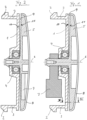
- a holding device 1 which is essentially circular, has, adjacent to its outer circumference, a plurality of holding arms 3 which are provided with latching lugs 2 and project essentially vertically. As soon as the wheel begins to rotate, the holding device 1 rotates with it.
- a carrier element 5 is rotatably mounted on the holding device 1 via a ball bearing 4 as a pivot bearing, with the corresponding axis of rotation 6 of the ball bearing agreeing with the axis of rotation of the wheel (not shown here) to which the holding device 1 is attached.
- the rotary bearing can in principle also be designed as a plain bearing or as another type of roller bearing.
- the support element is non-rotatably connected to a weight 7 whose center of gravity is eccentric to the axis of rotation 6 . This ensures that when the holding device 1 rotates, the carrier element 5 remains in a substantially upright, constant position so don't turn.
- a decorative body 8 which, for example, bears the logo of a vehicle or wheel rim manufacturer. When the wheel turns, this logo always stays in the same, upright position, so it doesn't turn with it.
- the decorative body 8 can also be designed as printing on the carrier element 5, as a printed foil element, etc.
- the side walls 10 and 11 of the gap are both designed as flat conical disks.
- a convex shape of the side walls 10 and/or 11 is also possible.
- both both side walls and only one side wall can be correspondingly convex. It is essential that the gap 9 between the side walls 10 and 11 has a divergent shape towards the outside.
- This divergent shape has the advantage that dirt particles are intercepted when they enter the gap 9 at the latest when they enter the area in which the clear width of the convergent gap 9 corresponds to the dimensions of the dirt particle. The dirt particle will thus slowed down in its radial movement and can then easily be thrown outwards again.
- the gap 9 can be seen in the top view.
- the side walls 10 and 11 are provided with a wave-like profile on the sides facing one another.
- a radiating pattern results from the elevations and depressions that are accordingly present. Because only one of the two side walls moves according to arrow 12, the clear width of gap 9 narrows and widens at any point, so that dirt particles are caught at this point as the gap narrows. In the subsequent phase of the widening of the gap, this dirt can then be thrown out of the gap more easily.
- the present invention thus makes it possible to significantly increase the operational reliability of a hub cap with a rotating carrier element.
Landscapes
- Engineering & Computer Science (AREA)
- Mechanical Engineering (AREA)
- Rolling Contact Bearings (AREA)
Description
- Die Erfindung betrifft eine Nabenabdeckung für ein Rad eines Fahrzeuges, insbesondere eines Kraftfahrzeuges, mit einer am Rad zu befestigenden Halteeinrichtung, an der um eine Drehachse drehbar ein Trägerelement zur Aufnahme eines Zierkörpers gelagert ist, wobei zwischen Trägerelement und Halteeinrichtung in Radialrichtung ein nach außen offener Spalt verläuft.
- Eine Vorrichtung dieser Art ist beispielsweise bekannt durch die
EP 2 607 096 . Ein Gegenstand gemäß diesem älteren Stand der Technik zeichnet sich insbesondere durch einen zur Drehachse konzentrischen Absatz an der Halteeinrichtung oder dem Trägerelement aus mit einer zu diesem Absatz komplementären Form des jeweiligen Gegenstückes. - Der Absatz zusammen mit der komplementären Form des Gegenstücks ist dabei wesentlich, da er Schmutzpartikel daran hindern soll, zu einem Drehlager an der Drehachse zu gelangen. Einzelne Schmutzpartikel, die bis zu diesem Absatz gelangen, sollen von diesem aufgehalten werden und werden durch die Drehbewegung der Halteeinrichtung und/oder des Trägerelements insbesondere aufgrund von Fliehkräften radial nach außen aus dem Spalt heraustransportiert, so dass die Nabenabdeckung sich bei Bewegung des Rades selbsttätig reinigen soll.
- Es hat sich jetzt aber herausgestellt, dass Schmutzpartikel, die auch eine im Wesentlichen ungleichmäßige, insbesondere nicht kugelige Form haben, sich in dem Spalt verklemmen können. Dies führt zu einer Funktionsstörung der Nabenabdeckung, so dass ihr Hauptzweck, nämlich das Logo eines Fahrzeug- oder Felgenherstellers, das auf dem Zierkörper angebracht ist, immer in einer gleichen aufrechten Position anzuzeigen, nicht sicher gewährleistet ist.
- Weitere vergleichbare Vorrichtungen sind außerdem bekannt aus der
US 2 869 262 A , derUS 5 659 989 A1 oder derDE 39 19 268 A1 . - Aufgabe der vorliegenden Erfindung ist es daher, eine Vorrichtung wie oben beschrieben derart weiter zu bilden, dass sie unempfindlicher gegen das Eindringen von Schmutzpartikeln wird.
- Diese Aufgabe wird erfindungsgemäß dadurch gelöst, dass sich der Spalt in Radialrichtung nach außen kontinuierlich erweitert.
- Die Erfindung hat den Vorteil, dass Schmutzpartikel, die sich in Radialrichtung auf die Drehachse zubewegen, bei einem Kontakt mit den Seitenwänden des Spaltes abgebremst werden und sich anschließend nur noch nach außen, aufgrund des sich zur Drehachse hin verjüngenden Spaltes aber nicht weiter nach innen bewegen können. Das Austragen von Schmutzpartikeln aus dem Spalt heraus wird auf diese Art und Weise deutlich verbessert.
- Bei einer bevorzugten Ausführungsform der Erfindung sind die Seitenwände des Spaltes im Wesentlichen geradlinig ausgebildet. Eine derartige Vorrichtung ist insbesondere fertigungstechnisch von Vorteil.
- Bei einer alternativen Ausführungsform hat zumindest eine Seitenwand des Spaltes eine konvexe Form. Hierdurch werden größere Schmutzpartikel bereits überproportional weiter außen von einem Eindringen in den Spalt bis zur Drehachse gehindert, was die Betriebssicherheit des Bauelementes verbessert.
- In Umfangsrichtung kann wenigstens eine der Seitenwände des Spaltes mit einer den Spalt in Umfangsrichtung abwechselnd erweiternden und verjüngenden Form versehen sein. Dies führt dazu, dass bei einer Rotation der Halteeinrichtung oder des Trägerelementes in dem sich verjüngenden Bereich zwischen diesen befindliche Partikel von den Seitenwänden ergriffen und in den sich erweiternden Bereich transportiert werden, von wo sie dann leicht nach außen abgeschleudert werden können.
- Die sich verengende oder verjüngende Kontur kann dabei bedarfsweise wellenförmig oder aber auch sägezahnartig ausgestaltet werden. Die sich durch diese Kontur an den Seitenwänden ergebenden Erhöhungen und Vertiefungen haben einen im Wesentlichen radialen Verlauf, so dass sich in der Frontalansicht der Seitenwände ein strahlenförmiges Muster ergibt.
- Weitere Vorteile und Merkmale der Erfindung ergeben sich aus der nachfolgenden Beschreibung eines Ausführungsbeispiels. Dabei zeigt:
- Fig. 1
- Schnittansicht durch eine erfindungsgemäße Nabenabdeckung;
- Fig. 2
- Schnittansicht durch eine alternative Ausführungsform der Nabenabdeckung;
- Fig. 3
- Schnittansicht entlang der Linie III-III in
Fig. 1 ; - Fig. 4
- Schnittansicht einer alternativen Ausführungsform entlang der Linie III-III in
Fig. 1 . - In der
Fig. 1 erkennt man den Längsschnitt durch eine Nabenabdeckung für das Rad eines Fahrzeuges. - Eine Halteeinrichtung 1, die im Wesentlichen kreisrund ist, hat benachbart zu ihrem äußeren Umfang mehrere mit Rastnasen 2 versehene im Wesentlichen senkrecht vorspringende Haltearme 3. Über diese Haltearme 3 wird die Halteeinrichtung 1 in einer korrespondierenden Ausnehmung im Bereich der Nabe eines Rades fixiert. Sobald das Rad in eine rotierende Bewegung kommt, wird die Halteeinrichtung 1 mitrotiert.
- In ihrem zentrischen mittleren Bereich ist an der Halteeinrichtung 1 über ein Kugellager 4 als Drehlager ein Trägerelement 5 verdrehbar gelagert, wobei die entsprechende Drehachse 6 des Kugellagers mit der Drehachse des (hier nicht dargestellten) Rades überstimmt, an dem die Halteeinrichtung 1 befestigt ist. Der Vollständigkeit halber sei erwähnt, dass das Drehlager grundsätzlich auch als Gleitlager ausgebildet sein kann oder als eine andere Art von Wälzlager. Besonders bevorzugt wird aber ein Hochleistungskugellager mit nichtschleifender Dichtung aus Edelstahl, das besonders betriebssicher ist.
- Das Trägerelement ist drehfest mit einem Gewicht 7 verbunden, dessen Schwerpunkt exzentrisch zur Drehachse 6 liegt. Dadurch wird erreicht, dass bei einer Rotation der Halteeinrichtung 1 das Trägerelement 5 in einer im Wesentlichen aufrechten gleichbleibenden Position verbleibt, sich also nicht mitdreht. Dadurch besteht die Möglichkeit, das Trägerelement 5 auf seiner der Halteeinrichtung 1 abgewandten Seite mit einem Zierkörper 8 zu versehen, der beispielsweise das Logo eines Fahrzeug- oder Felgenherstellers trägt. Bei einer Drehung des Rades bleibt dieses Logo dann immer in der gleichen, aufrechten Stellung, dreht sich also nicht mit. Der Zierkörper 8 kann dabei bedarfsweise auch als Bedruckung des Trägerelementes 5 ausgebildet sein, als bedrucktes Folienelement etc.
- Zwischen dem Trägerelement 5 und der Halteeinrichtung 1 befindet sich ein Spalt 9, so dass das Trägerelement 5 und die Halteeinrichtung 1 räumlich voneinander getrennt sind und nicht aneinander reiben.
- Da Fahrzeugräder auch Verschmutzungen in Form von Staub, Matsch, Sand etc. ausgesetzt sind, soll sichergestellt sein, dass in den Spalt 9 gelangende Verschmutzungen nicht bis zum Kugellager 4 gelangen. Dies gilt auch dann, wenn dieses Kugellager wie oben angesprochen als Hochleistungskugellager mit einer nichtschleifenden Dichtung versehen ist. Um dies zu erreichen, ist der nach außen offene Spalt 9 sich nach außen kontinuierlich erweiternd ausgebildet.
- Im hier dargestellten Beispiel sind die Seitenwände 10 und 11 des Spaltes dafür beide als flache Kegelscheiben ausgebildet.
- Es ist aber auch im Rahmen der Erfindung, wenn lediglich eine der beiden Seitenflächen 10 oder 11 eine derartige flache kegelscheibenartige Form hat.
- Außer einer linear gradlinig verlaufenden Kegelfläche ist auch eine konvexe Form der Seitenwände 10 und/oder 11 möglich. Auch hier können sowohl beide als auch nur eine Seitenwand entsprechend konvex ausgestaltet sein. Wesentlich ist, dass der Spalt 9 zwischen den Seitenwänden 10 und 11 nach außen eine divergente Form hat.
- Diese divergente Form hat den Vorteil, dass Schmutzpartikel beim Eindringen in den Spalt 9 spätestens abgefangen werden, wenn sie in den Bereich kommen, in dem die lichte Weite des konvergenten Spaltes 9 den Abmessungen des Schmutzpartikels entspricht. Der Schmutzpartikel wird damit in seiner radialen Bewegung abgebremst und kann dann leicht wieder nach außen abgeschleudert werden.
- In der
Fig. 2 sind gleiche Teile mit gleichen Bezugszeichen versehen. Als wesentlicher Unterschied ist zu sehen, dass das Gewicht 7 in das Trägerelement 5 integriert ist, so dass der für die Nabenabdeckung benötigte Bauraum verringert wird. - In der
Fig. 3 ist noch eine Schnittansicht dargestellt, in der der Spalt 9 in der Aufsicht zu erkennen ist. Man sieht, dass die Seitenwände 10 bzw. 11 an den einander zugewandten Seiten mit einem wellenartigen Profil versehen sind. In der Frontalansicht der Seitenwände ergibt sich durch die demgemäß vorhandenen Erhöhungen und Vertiefungen ein strahlenförmiges Muster. Dadurch, dass sich lediglich eine der beiden Seitenwände entsprechend dem Pfeil 12 bewegt, verengt und erweitert sich an einer beliebigen Stelle die lichte Weite des Spaltes 9, so dass sich an dieser Stelle bei sich verengendem Spalt Schmutzpartikel fangen. In der sich anschließenden Phase der Erweiterung des Spaltes kann dieser Schmutz dann leichter wieder aus dem Spalt herausgeschleudert werden. - In der
Fig. 4 ist diesbezüglich eine alternative Ausführungsform dargestellt, bei der lediglich eine Seitenwand 11 mit einem im Wesentlichen sägezahnförmigen Profil versehen ist. Auch hier hat die Seitenfläche in der Frontalansicht somit ein strahlenförmiges Muster. Des Weiteren wird auch hier bei Rotation einer mit diesem Profil versehen Seitenwand entsprechend dem Pfeil 12 sich die lokale Weite des Spaltes dem Sägezahnprofil folgend verändern, so dass in diesen Spalt geratender Schmutz zunächst abgebremst und anschließend in dem sich wieder erweiternden Bereich nach außen abgeschleudert werden kann. - Insgesamt gibt die vorliegende Erfindung somit die Möglichkeit, die Betriebssicherheit einer Nabenabdeckung mit einem rotierenden Trägerelement deutlich zu erhöhen.
-
- 1
- Halteeinrichtung
- 2
- Rastnase
- 3
- Haltearme
- 4
- Kugellager
- 5
- Trägerelement
- 6
- Drehachse
- 7
- Gewicht
- 8
- Zierkörper
- 9
- Spalt
- 10
- Seitenwand
- 11
- Seitenwand
- 12
- Pfeil
Claims (6)
- Nabenabdeckung für ein Rad eines Fahrzeuges, insbesondere eines Kraftfahrzeuges, mit einer am Rad zu befestigenden Halteeinrichtung (1), an der um eine Drehachse (6) drehbar ein Trägerelement (5) zur Aufnahme eines Zierkörpers (8) gelagert ist, wobei zwischen Trägerelement (5) und Halteeinrichtung (1) in Radialrichtung ein nach außen offener Spalt (9) verläuft,
dadurch gekennzeichnet,
dass sich der Spalt (9) in Radialrichtung nach außen kontinuierlich erweitert. - Nabenabdeckung gemäß Anspruch 1,
dadurch gekennzeichnet,
dass die Seitenwände (10, 11) des Spaltes (9) im Wesentlichen gradlinig ausgebildet sind. - Nabenabdeckung gemäß Anspruch 1,
dadurch gekennzeichnet,
dass mindestens eine Seitenwand (10, 11) des Spaltes (9) eine konvexe Form hat. - Nabenabdeckung gemäß einem oder mehreren der vorhergehenden Ansprüche,
dadurch gekennzeichnet,
dass in Umfangsrichtung wenigstens eine der Seitenwände (10, 11) mit einer den Spalt in Umfangsrichtung abwechselnd erweiternden und verjüngenden Form versehen ist. - Nabenabdeckung gemäß Anspruch 4,
dadurch gekennzeichnet,
dass die Form wellenförmig ist. - Nabenabdeckung gemäß Anspruch 4,
dadurch gekennzeichnet,
dass die Form sägezahnförmig ist.
Applications Claiming Priority (1)
| Application Number | Priority Date | Filing Date | Title |
|---|---|---|---|
| DE202018004505.5U DE202018004505U1 (de) | 2018-09-27 | 2018-09-27 | Radnabenabdeckung |
Publications (2)
| Publication Number | Publication Date |
|---|---|
| EP3628508A1 EP3628508A1 (de) | 2020-04-01 |
| EP3628508B1 true EP3628508B1 (de) | 2023-03-22 |
Family
ID=68069655
Family Applications (1)
| Application Number | Title | Priority Date | Filing Date |
|---|---|---|---|
| EP19199759.2A Active EP3628508B1 (de) | 2018-09-27 | 2019-09-26 | Radnabenabdeckung |
Country Status (2)
| Country | Link |
|---|---|
| EP (1) | EP3628508B1 (de) |
| DE (1) | DE202018004505U1 (de) |
Families Citing this family (3)
| Publication number | Priority date | Publication date | Assignee | Title |
|---|---|---|---|---|
| DE102019202507B4 (de) * | 2019-02-25 | 2021-02-18 | Volkswagen Aktiengesellschaft | Drehbares Zierelement |
| DE102023000448B4 (de) | 2023-02-13 | 2024-06-06 | Mercedes-Benz Group AG | Radnabenabdeckung für ein Fahrzeug |
| IT202300008781A1 (it) * | 2023-05-04 | 2024-11-04 | Spm Spa | Dispositivo coprimozzo flottante per una ruota di un veicolo |
Family Cites Families (4)
| Publication number | Priority date | Publication date | Assignee | Title |
|---|---|---|---|---|
| US2869262A (en) * | 1957-06-03 | 1959-01-20 | Charles D Lucas | Wheel-supported advertizing signs |
| DE3919268A1 (de) * | 1989-06-13 | 1991-01-03 | Friedrich Kutter | Radkappe fuer ein fahrzeugrad mit drehbarem oberteil |
| US5659989A (en) * | 1994-07-13 | 1997-08-26 | Hsiao; Leslie | Wheel cover |
| DE102011056944A1 (de) * | 2011-12-22 | 2013-06-27 | Heinz Wilhelm | Radnabenabdeckung |
-
2018
- 2018-09-27 DE DE202018004505.5U patent/DE202018004505U1/de active Active
-
2019
- 2019-09-26 EP EP19199759.2A patent/EP3628508B1/de active Active
Also Published As
| Publication number | Publication date |
|---|---|
| DE202018004505U1 (de) | 2020-01-03 |
| EP3628508A1 (de) | 2020-04-01 |
Similar Documents
| Publication | Publication Date | Title |
|---|---|---|
| EP3628508B1 (de) | Radnabenabdeckung | |
| EP2758254B1 (de) | Mecanumrad sowie mecanumradfahrzeug | |
| EP0407719B1 (de) | Radlager für Anhängerachsen | |
| DE3809904A1 (de) | Vorrichtung zur abdichtung und erzeugung von elektrischen impulsen | |
| DE69811661T2 (de) | Hochleistungsbremsscheibe mit Nuten zur Entwässerung und zur optischen Verschleisskontrolle | |
| WO2012019803A1 (de) | Dichtungsanordnung für wälzlager | |
| DE1905306U (de) | Dichtring. | |
| EP2547569B1 (de) | Verwendung einer mobilen vorrichtung, medizinisches gerät und bremsvorrichtung | |
| DE102007045043B4 (de) | Dichtring | |
| DE102020124608A1 (de) | Dichtvorrichtung mit dynamischer Dichtwirkung, insbesondere für Wälzlager | |
| EP4497608A1 (de) | Rollenbremse für doppelte kofferlenkrolle | |
| EP2607096B1 (de) | Radnabenabdeckung | |
| EP2692542A1 (de) | Reifen-Zierring | |
| EP2491641B1 (de) | Elektrische maschine, hydraulikeinheit | |
| EP2210463A1 (de) | Tiefenführungsscheibe mit gekrümmten und gegen Drehrichtung weisenden Stegen | |
| DE102017205270A1 (de) | Kreuzgelenklager | |
| EP4204706B1 (de) | Rolleneinheit für ein fahrzeug und fahrzeug | |
| EP0050302A1 (de) | Dichtvorsatz für ein Pendellagergehäuse | |
| EP2422997B1 (de) | Rolle für verfahrbare Gegenstände | |
| DE3238634C2 (de) | Förderbandtragrolle | |
| DE10208972A1 (de) | Tragrolle | |
| EP2151593B1 (de) | Dichtung für eine Radnabe | |
| DE102006010617A1 (de) | Lager mit bevorzugter Ruhestellung | |
| DE102020131037B4 (de) | Laufrolle und Transportgerät mit einer Laufrolle | |
| DE102016205405A1 (de) | Nutzfahrzeug-Radnabe mit mehrteiligem Nabendeckel |
Legal Events
| Date | Code | Title | Description |
|---|---|---|---|
| PUAI | Public reference made under article 153(3) epc to a published international application that has entered the european phase |
Free format text: ORIGINAL CODE: 0009012 |
|
| STAA | Information on the status of an ep patent application or granted ep patent |
Free format text: STATUS: THE APPLICATION HAS BEEN PUBLISHED |
|
| AK | Designated contracting states |
Kind code of ref document: A1 Designated state(s): AL AT BE BG CH CY CZ DE DK EE ES FI FR GB GR HR HU IE IS IT LI LT LU LV MC MK MT NL NO PL PT RO RS SE SI SK SM TR |
|
| AX | Request for extension of the european patent |
Extension state: BA ME |
|
| STAA | Information on the status of an ep patent application or granted ep patent |
Free format text: STATUS: REQUEST FOR EXAMINATION WAS MADE |
|
| 17P | Request for examination filed |
Effective date: 20201001 |
|
| RBV | Designated contracting states (corrected) |
Designated state(s): AL AT BE BG CH CY CZ DE DK EE ES FI FR GB GR HR HU IE IS IT LI LT LU LV MC MK MT NL NO PL PT RO RS SE SI SK SM TR |
|
| GRAP | Despatch of communication of intention to grant a patent |
Free format text: ORIGINAL CODE: EPIDOSNIGR1 |
|
| STAA | Information on the status of an ep patent application or granted ep patent |
Free format text: STATUS: GRANT OF PATENT IS INTENDED |
|
| INTG | Intention to grant announced |
Effective date: 20221019 |
|
| GRAS | Grant fee paid |
Free format text: ORIGINAL CODE: EPIDOSNIGR3 |
|
| GRAA | (expected) grant |
Free format text: ORIGINAL CODE: 0009210 |
|
| STAA | Information on the status of an ep patent application or granted ep patent |
Free format text: STATUS: THE PATENT HAS BEEN GRANTED |
|
| AK | Designated contracting states |
Kind code of ref document: B1 Designated state(s): AL AT BE BG CH CY CZ DE DK EE ES FI FR GB GR HR HU IE IS IT LI LT LU LV MC MK MT NL NO PL PT RO RS SE SI SK SM TR |
|
| REG | Reference to a national code |
Ref country code: GB Ref legal event code: FG4D Free format text: NOT ENGLISH |
|
| REG | Reference to a national code |
Ref country code: CH Ref legal event code: EP |
|
| REG | Reference to a national code |
Ref country code: DE Ref legal event code: R096 Ref document number: 502019007264 Country of ref document: DE |
|
| REG | Reference to a national code |
Ref country code: IE Ref legal event code: FG4D Free format text: LANGUAGE OF EP DOCUMENT: GERMAN |
|
| REG | Reference to a national code |
Ref country code: AT Ref legal event code: REF Ref document number: 1555089 Country of ref document: AT Kind code of ref document: T Effective date: 20230415 |
|
| REG | Reference to a national code |
Ref country code: LT Ref legal event code: MG9D |
|
| REG | Reference to a national code |
Ref country code: NL Ref legal event code: MP Effective date: 20230322 |
|
| PG25 | Lapsed in a contracting state [announced via postgrant information from national office to epo] |
Ref country code: RS Free format text: LAPSE BECAUSE OF FAILURE TO SUBMIT A TRANSLATION OF THE DESCRIPTION OR TO PAY THE FEE WITHIN THE PRESCRIBED TIME-LIMIT Effective date: 20230322 Ref country code: NO Free format text: LAPSE BECAUSE OF FAILURE TO SUBMIT A TRANSLATION OF THE DESCRIPTION OR TO PAY THE FEE WITHIN THE PRESCRIBED TIME-LIMIT Effective date: 20230622 Ref country code: LV Free format text: LAPSE BECAUSE OF FAILURE TO SUBMIT A TRANSLATION OF THE DESCRIPTION OR TO PAY THE FEE WITHIN THE PRESCRIBED TIME-LIMIT Effective date: 20230322 Ref country code: LT Free format text: LAPSE BECAUSE OF FAILURE TO SUBMIT A TRANSLATION OF THE DESCRIPTION OR TO PAY THE FEE WITHIN THE PRESCRIBED TIME-LIMIT Effective date: 20230322 Ref country code: HR Free format text: LAPSE BECAUSE OF FAILURE TO SUBMIT A TRANSLATION OF THE DESCRIPTION OR TO PAY THE FEE WITHIN THE PRESCRIBED TIME-LIMIT Effective date: 20230322 |
|
| PG25 | Lapsed in a contracting state [announced via postgrant information from national office to epo] |
Ref country code: SE Free format text: LAPSE BECAUSE OF FAILURE TO SUBMIT A TRANSLATION OF THE DESCRIPTION OR TO PAY THE FEE WITHIN THE PRESCRIBED TIME-LIMIT Effective date: 20230322 Ref country code: NL Free format text: LAPSE BECAUSE OF FAILURE TO SUBMIT A TRANSLATION OF THE DESCRIPTION OR TO PAY THE FEE WITHIN THE PRESCRIBED TIME-LIMIT Effective date: 20230322 Ref country code: GR Free format text: LAPSE BECAUSE OF FAILURE TO SUBMIT A TRANSLATION OF THE DESCRIPTION OR TO PAY THE FEE WITHIN THE PRESCRIBED TIME-LIMIT Effective date: 20230623 Ref country code: FI Free format text: LAPSE BECAUSE OF FAILURE TO SUBMIT A TRANSLATION OF THE DESCRIPTION OR TO PAY THE FEE WITHIN THE PRESCRIBED TIME-LIMIT Effective date: 20230322 |
|
| PG25 | Lapsed in a contracting state [announced via postgrant information from national office to epo] |
Ref country code: SM Free format text: LAPSE BECAUSE OF FAILURE TO SUBMIT A TRANSLATION OF THE DESCRIPTION OR TO PAY THE FEE WITHIN THE PRESCRIBED TIME-LIMIT Effective date: 20230322 Ref country code: RO Free format text: LAPSE BECAUSE OF FAILURE TO SUBMIT A TRANSLATION OF THE DESCRIPTION OR TO PAY THE FEE WITHIN THE PRESCRIBED TIME-LIMIT Effective date: 20230322 Ref country code: PT Free format text: LAPSE BECAUSE OF FAILURE TO SUBMIT A TRANSLATION OF THE DESCRIPTION OR TO PAY THE FEE WITHIN THE PRESCRIBED TIME-LIMIT Effective date: 20230724 Ref country code: ES Free format text: LAPSE BECAUSE OF FAILURE TO SUBMIT A TRANSLATION OF THE DESCRIPTION OR TO PAY THE FEE WITHIN THE PRESCRIBED TIME-LIMIT Effective date: 20230322 Ref country code: EE Free format text: LAPSE BECAUSE OF FAILURE TO SUBMIT A TRANSLATION OF THE DESCRIPTION OR TO PAY THE FEE WITHIN THE PRESCRIBED TIME-LIMIT Effective date: 20230322 |
|
| PG25 | Lapsed in a contracting state [announced via postgrant information from national office to epo] |
Ref country code: SK Free format text: LAPSE BECAUSE OF FAILURE TO SUBMIT A TRANSLATION OF THE DESCRIPTION OR TO PAY THE FEE WITHIN THE PRESCRIBED TIME-LIMIT Effective date: 20230322 Ref country code: PL Free format text: LAPSE BECAUSE OF FAILURE TO SUBMIT A TRANSLATION OF THE DESCRIPTION OR TO PAY THE FEE WITHIN THE PRESCRIBED TIME-LIMIT Effective date: 20230322 Ref country code: IS Free format text: LAPSE BECAUSE OF FAILURE TO SUBMIT A TRANSLATION OF THE DESCRIPTION OR TO PAY THE FEE WITHIN THE PRESCRIBED TIME-LIMIT Effective date: 20230722 |
|
| P01 | Opt-out of the competence of the unified patent court (upc) registered |
Effective date: 20231117 |
|
| REG | Reference to a national code |
Ref country code: DE Ref legal event code: R097 Ref document number: 502019007264 Country of ref document: DE |
|
| PLBE | No opposition filed within time limit |
Free format text: ORIGINAL CODE: 0009261 |
|
| STAA | Information on the status of an ep patent application or granted ep patent |
Free format text: STATUS: NO OPPOSITION FILED WITHIN TIME LIMIT |
|
| PG25 | Lapsed in a contracting state [announced via postgrant information from national office to epo] |
Ref country code: SI Free format text: LAPSE BECAUSE OF FAILURE TO SUBMIT A TRANSLATION OF THE DESCRIPTION OR TO PAY THE FEE WITHIN THE PRESCRIBED TIME-LIMIT Effective date: 20230322 Ref country code: DK Free format text: LAPSE BECAUSE OF FAILURE TO SUBMIT A TRANSLATION OF THE DESCRIPTION OR TO PAY THE FEE WITHIN THE PRESCRIBED TIME-LIMIT Effective date: 20230322 Ref country code: CZ Free format text: LAPSE BECAUSE OF FAILURE TO SUBMIT A TRANSLATION OF THE DESCRIPTION OR TO PAY THE FEE WITHIN THE PRESCRIBED TIME-LIMIT Effective date: 20230322 |
|
| 26N | No opposition filed |
Effective date: 20240102 |
|
| REG | Reference to a national code |
Ref country code: CH Ref legal event code: PL |
|
| PG25 | Lapsed in a contracting state [announced via postgrant information from national office to epo] |
Ref country code: LU Free format text: LAPSE BECAUSE OF NON-PAYMENT OF DUE FEES Effective date: 20230926 |
|
| REG | Reference to a national code |
Ref country code: BE Ref legal event code: MM Effective date: 20230930 |
|
| GBPC | Gb: european patent ceased through non-payment of renewal fee |
Effective date: 20230926 |
|
| PG25 | Lapsed in a contracting state [announced via postgrant information from national office to epo] |
Ref country code: LU Free format text: LAPSE BECAUSE OF NON-PAYMENT OF DUE FEES Effective date: 20230926 Ref country code: MC Free format text: LAPSE BECAUSE OF FAILURE TO SUBMIT A TRANSLATION OF THE DESCRIPTION OR TO PAY THE FEE WITHIN THE PRESCRIBED TIME-LIMIT Effective date: 20230322 |
|
| REG | Reference to a national code |
Ref country code: IE Ref legal event code: MM4A |
|
| PG25 | Lapsed in a contracting state [announced via postgrant information from national office to epo] |
Ref country code: IE Free format text: LAPSE BECAUSE OF NON-PAYMENT OF DUE FEES Effective date: 20230926 |
|
| PG25 | Lapsed in a contracting state [announced via postgrant information from national office to epo] |
Ref country code: GB Free format text: LAPSE BECAUSE OF NON-PAYMENT OF DUE FEES Effective date: 20230926 |
|
| PG25 | Lapsed in a contracting state [announced via postgrant information from national office to epo] |
Ref country code: CH Free format text: LAPSE BECAUSE OF NON-PAYMENT OF DUE FEES Effective date: 20230930 |
|
| PG25 | Lapsed in a contracting state [announced via postgrant information from national office to epo] |
Ref country code: IE Free format text: LAPSE BECAUSE OF NON-PAYMENT OF DUE FEES Effective date: 20230926 Ref country code: GB Free format text: LAPSE BECAUSE OF NON-PAYMENT OF DUE FEES Effective date: 20230926 Ref country code: CH Free format text: LAPSE BECAUSE OF NON-PAYMENT OF DUE FEES Effective date: 20230930 |
|
| PG25 | Lapsed in a contracting state [announced via postgrant information from national office to epo] |
Ref country code: BE Free format text: LAPSE BECAUSE OF NON-PAYMENT OF DUE FEES Effective date: 20230930 |
|
| PG25 | Lapsed in a contracting state [announced via postgrant information from national office to epo] |
Ref country code: BG Free format text: LAPSE BECAUSE OF FAILURE TO SUBMIT A TRANSLATION OF THE DESCRIPTION OR TO PAY THE FEE WITHIN THE PRESCRIBED TIME-LIMIT Effective date: 20230322 |
|
| PG25 | Lapsed in a contracting state [announced via postgrant information from national office to epo] |
Ref country code: BG Free format text: LAPSE BECAUSE OF FAILURE TO SUBMIT A TRANSLATION OF THE DESCRIPTION OR TO PAY THE FEE WITHIN THE PRESCRIBED TIME-LIMIT Effective date: 20230322 |
|
| PG25 | Lapsed in a contracting state [announced via postgrant information from national office to epo] |
Ref country code: CY Free format text: LAPSE BECAUSE OF FAILURE TO SUBMIT A TRANSLATION OF THE DESCRIPTION OR TO PAY THE FEE WITHIN THE PRESCRIBED TIME-LIMIT; INVALID AB INITIO Effective date: 20190926 |
|
| PG25 | Lapsed in a contracting state [announced via postgrant information from national office to epo] |
Ref country code: HU Free format text: LAPSE BECAUSE OF FAILURE TO SUBMIT A TRANSLATION OF THE DESCRIPTION OR TO PAY THE FEE WITHIN THE PRESCRIBED TIME-LIMIT; INVALID AB INITIO Effective date: 20190926 |
|
| PGFP | Annual fee paid to national office [announced via postgrant information from national office to epo] |
Ref country code: DE Payment date: 20250919 Year of fee payment: 7 |
|
| PGFP | Annual fee paid to national office [announced via postgrant information from national office to epo] |
Ref country code: FR Payment date: 20250922 Year of fee payment: 7 |
|
| REG | Reference to a national code |
Ref country code: AT Ref legal event code: MM01 Ref document number: 1555089 Country of ref document: AT Kind code of ref document: T Effective date: 20240926 |
|
| PG25 | Lapsed in a contracting state [announced via postgrant information from national office to epo] |
Ref country code: TR Free format text: LAPSE BECAUSE OF FAILURE TO SUBMIT A TRANSLATION OF THE DESCRIPTION OR TO PAY THE FEE WITHIN THE PRESCRIBED TIME-LIMIT Effective date: 20230322 |
|
| PG25 | Lapsed in a contracting state [announced via postgrant information from national office to epo] |
Ref country code: AT Free format text: LAPSE BECAUSE OF NON-PAYMENT OF DUE FEES Effective date: 20240926 |
|
| PGFP | Annual fee paid to national office [announced via postgrant information from national office to epo] |
Ref country code: IT Payment date: 20250930 Year of fee payment: 7 |
|
| PGFP | Annual fee paid to national office [announced via postgrant information from national office to epo] |
Ref country code: AT Payment date: 20260410 Year of fee payment: 5 |