EP3628451A1 - Fault reaction, fault isolation, and graceful degradation in a robotic system - Google Patents
Fault reaction, fault isolation, and graceful degradation in a robotic system Download PDFInfo
- Publication number
- EP3628451A1 EP3628451A1 EP19211066.6A EP19211066A EP3628451A1 EP 3628451 A1 EP3628451 A1 EP 3628451A1 EP 19211066 A EP19211066 A EP 19211066A EP 3628451 A1 EP3628451 A1 EP 3628451A1
- Authority
- EP
- European Patent Office
- Prior art keywords
- fault
- arm
- robotic
- failed
- safe state
- Prior art date
- Legal status (The legal status is an assumption and is not a legal conclusion. Google has not performed a legal analysis and makes no representation as to the accuracy of the status listed.)
- Granted
Links
Images


Classifications
-
- B—PERFORMING OPERATIONS; TRANSPORTING
- B25—HAND TOOLS; PORTABLE POWER-DRIVEN TOOLS; MANIPULATORS
- B25J—MANIPULATORS; CHAMBERS PROVIDED WITH MANIPULATION DEVICES
- B25J9/00—Program-controlled manipulators
- B25J9/16—Program controls
- B25J9/1674—Program controls characterised by safety, monitoring, diagnostic
-
- A—HUMAN NECESSITIES
- A61—MEDICAL OR VETERINARY SCIENCE; HYGIENE
- A61B—DIAGNOSIS; SURGERY; IDENTIFICATION
- A61B34/00—Computer-aided surgery; Manipulators or robots specially adapted for use in surgery
- A61B34/30—Surgical robots
-
- A—HUMAN NECESSITIES
- A61—MEDICAL OR VETERINARY SCIENCE; HYGIENE
- A61B—DIAGNOSIS; SURGERY; IDENTIFICATION
- A61B34/00—Computer-aided surgery; Manipulators or robots specially adapted for use in surgery
- A61B34/30—Surgical robots
- A61B34/37—Leader-follower robots
-
- B—PERFORMING OPERATIONS; TRANSPORTING
- B25—HAND TOOLS; PORTABLE POWER-DRIVEN TOOLS; MANIPULATORS
- B25J—MANIPULATORS; CHAMBERS PROVIDED WITH MANIPULATION DEVICES
- B25J9/00—Program-controlled manipulators
- B25J9/0084—Program-controlled manipulators comprising a plurality of manipulators
-
- G—PHYSICS
- G05—CONTROLLING; REGULATING
- G05B—CONTROL OR REGULATING SYSTEMS IN GENERAL; FUNCTIONAL ELEMENTS OF SUCH SYSTEMS; MONITORING OR TESTING ARRANGEMENTS FOR SUCH SYSTEMS OR ELEMENTS
- G05B2219/00—Program-control systems
- G05B2219/30—Nc systems
- G05B2219/31—From computer integrated manufacturing till monitoring
- G05B2219/31366—Operate faulty tool in degraded mode
-
- G—PHYSICS
- G05—CONTROLLING; REGULATING
- G05B—CONTROL OR REGULATING SYSTEMS IN GENERAL; FUNCTIONAL ELEMENTS OF SUCH SYSTEMS; MONITORING OR TESTING ARRANGEMENTS FOR SUCH SYSTEMS OR ELEMENTS
- G05B2219/00—Program-control systems
- G05B2219/30—Nc systems
- G05B2219/40—Robotics, robotics mapping to robotics vision
- G05B2219/40204—Each fault condition has a different recovery procedure
-
- G—PHYSICS
- G05—CONTROLLING; REGULATING
- G05B—CONTROL OR REGULATING SYSTEMS IN GENERAL; FUNCTIONAL ELEMENTS OF SUCH SYSTEMS; MONITORING OR TESTING ARRANGEMENTS FOR SUCH SYSTEMS OR ELEMENTS
- G05B2219/00—Program-control systems
- G05B2219/30—Nc systems
- G05B2219/40—Robotics, robotics mapping to robotics vision
- G05B2219/40205—Multiple arm systems
-
- Y—GENERAL TAGGING OF NEW TECHNOLOGICAL DEVELOPMENTS; GENERAL TAGGING OF CROSS-SECTIONAL TECHNOLOGIES SPANNING OVER SEVERAL SECTIONS OF THE IPC; TECHNICAL SUBJECTS COVERED BY FORMER USPC CROSS-REFERENCE ART COLLECTIONS [XRACs] AND DIGESTS
- Y02—TECHNOLOGIES OR APPLICATIONS FOR MITIGATION OR ADAPTATION AGAINST CLIMATE CHANGE
- Y02P—CLIMATE CHANGE MITIGATION TECHNOLOGIES IN THE PRODUCTION OR PROCESSING OF GOODS
- Y02P90/00—Enabling technologies with a potential contribution to greenhouse gas [GHG] emissions mitigation
- Y02P90/02—Total factory control, e.g. smart factories, flexible manufacturing systems [FMS] or integrated manufacturing systems [IMS]
-
- Y—GENERAL TAGGING OF NEW TECHNOLOGICAL DEVELOPMENTS; GENERAL TAGGING OF CROSS-SECTIONAL TECHNOLOGIES SPANNING OVER SEVERAL SECTIONS OF THE IPC; TECHNICAL SUBJECTS COVERED BY FORMER USPC CROSS-REFERENCE ART COLLECTIONS [XRACs] AND DIGESTS
- Y10—TECHNICAL SUBJECTS COVERED BY FORMER USPC
- Y10S—TECHNICAL SUBJECTS COVERED BY FORMER USPC CROSS-REFERENCE ART COLLECTIONS [XRACs] AND DIGESTS
- Y10S901/00—Robots
- Y10S901/02—Arm motion controller
Definitions
- the present invention generally relates to robotic systems and in particular, to fault reaction, fault isolation, and graceful degradation in a robotic system.
- Robotic systems having one or more user controlled robotic arms are used in many applications. As one example, see US 7,865,266 B2 , entitled “Cooperative Minimally Invasive Telesurgical System,” which is incorporated herein by reference. Additional examples may be found in manufacturing, construction, hazardous material handling, and other applications such as those using teleoperation.
- fault tolerant systems may be employed such as those providing triple redundancy so that a fault may be readily determined and if one component fails, a surviving component may still provide the function.
- Providing redundant components adds to system cost.
- preventive maintenance techniques may be employed to minimize the occurrences of such faults. However, unexpected faults may still occur.
- the entire system may be turned off for safety reasons until the fault can be corrected.
- the robotic system may still be usable to accomplish a primary or secondary task in a degraded state. In this case, it may be advantageous to allow the system to continue operating in the degraded state. Other times, the fault may not be persistent. In this case, clearing the fault and continuing full use of the robotic system may be possible.
- one object of one or more aspects of the present invention is a fault handling scheme which ensures that the system is automatically placed in a safe state upon detection of a fault.
- Another object of one or more aspects of the present invention is a fault handling scheme which facilitates a graceful degradation of the robotic system after detection of a fault that cannot be cleared.
- one aspect is a method for fault reaction, fault isolation, and graceful degradation in a robotic system having a plurality of robotic arms.
- the method comprises: detecting a fault in a failed arm of the plurality of robotic arms; placing the failed arm into a safe state; determining whether the fault should be treated as a system fault or a local fault; and placing non-failed arms of the plurality of robotic arms in the safe state only if the fault is to be treated as a system fault.
- Another aspect is a robotic system comprising: a plurality of robotic arms, a plurality of arm processors, and a supervisor processor.
- Each arm processor is operatively coupled to a corresponding one of the plurality robotic arms.
- Each robotic arm has a plurality of motors for actuating degrees of freedom movement of the robotic arm.
- Each robotic arm has one or more nodes for controlling corresponding motors of the robotic arm.
- Each node and arm processor is configured to detect an occurrence of a fault affecting the node or arm processor, to place the node or arm processor into a safe state upon detecting the occurrence of the fault, to propagate a fault notification through a failed arm that includes the node or is operatively coupled to the arm processor, to diagnose the fault, and to send an error message including information of the fault to the supervisor processor.
- Each node and arm processor is also configured to place the node or arm processor into a safe state upon receiving a fault notification from another source.
- the supervisor processor is configured to receive the error message from the failed node or arm processor, to determine whether the detected fault should be treated as a system fault or a local fault by using information in the error message, and to transmit a fault notification to arm processors corresponding to all non-failed arms of the plurality of robotic arms only if the detected fault is to be treated as a system fault.
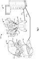
- FIG. 1 illustrates, as an example, a perspective view of a robotic system 1000 that includes a user console 100, a robotic arms cart 110, and a vision cart 170, which communicate with one another through cables 181, 182.
- the user console 100 includes a stereo viewer 101, hand-manipulatable master controllers 102, 103, and at least one foot pedal 104.
- the robotic arms cart 110 includes a base 120, a column 121 that is attached to the base 120, and robotic arms 111, 113, 115, 117 that are attached to the column 121 and that are adapted to hold, move and manipulate attachable instruments 112, 114, 116, 118.
- the robotic arms 111, 113, 117 hold tool instruments 112, 114, 118 and the robotic arm 115 holds a stereoscopic camera instrument 116.
- each of the robotic arms 111, 113, 115, 117 may hold a different type of instrument or hold no instrument at all while a work procedure is being performed.
- a second image capture device employing a different imaging modality may replace the tool instrument 112 being held by the robotic arm 111.
- robotic arm 111 may be left unused with no instrument attached to it during all or a part of a work procedure.
- the stereoscopic camera instrument 116 captures stereo images which are continuously transmitted as a video stream to the vision cart 170.
- the vision cart 170 processes each pair of stereo images as it is received and transmits the processed pair of stereo images to the user console 100 for display on the stereo viewer 101 in real time.
- an user may view stereo images of a work site which have been captured by the stereoscopic camera instrument 116 while telerobotically manipulating the tool instruments 112, 114, 118 and/or the stereoscopic camera instrument 116 by manipulating associated ones of the master controllers 102, 103 and/or foot pedal 104.
- Master/slave control systems are provided in the robotic system 1000 to facilitate such telerobotic manipulations.
- the robotic arms 111, 113, 115, 117 may be moved up or down in a vertical direction (e.g., towards the ceiling or towards the floor).
- Each of the robotic arms 111, 113, 115, 117 preferably includes a manipulator and a set-up arm.
- the manipulator is adapted to hold an instrument and manipulate it about a pivot point.
- the set-up arm is adapted to horizontally translate the manipulator in space so that the manipulator's held instrument and the instrument's pivot point are also horizontally translated in space.
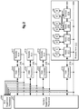
- FIG. 2 illustrates, as an example, a block diagram of components of the robotic system 1000 that cooperatively interact to perform various aspects of fault reaction, fault isolation, and graceful degradation in the robotic system 1000.
- Each of the robotic arms 111, 113, 115, 117 comprises one or more nodes.
- Each node controls one or more motors which actuate joints and/or linkages in the robotic arm to effect the degrees of freedom movement of the robotic arm.
- Each node also controls one or more brakes for stopping the rotation of the motors.
- the robotic arm 111 has a plurality of motors (e.g., 21, 23, 25, 27), a plurality of brakes (e.g., 22, 24, 26, 28), and a plurality of nodes (e.g., 211, 212, 213).
- Each of nodes 211, 212 controls a single motor/brake pair.
- Node 213, on the other hand, controls two motor/brake pairs.
- Other nodes may control more than two motor/brake pairs.
- a sensor processing unit 214 is included to provide motor displacement sensor information to the node 213 for control purposes.
- Robotic arms 113, 115, 117 are similarly configured as robotic arm 111 with motors, brakes, and nodes.
- Each robotic arm is operatively coupled to an arm processor.
- arm processor 210 is operatively coupled to nodes of the robotic arm 111
- arm processor 220 is operatively coupled to nodes of the robotic arm 113
- arm processor 230 is operatively coupled to nodes of the robotic arm 115
- arm processor 240 is operatively coupled to nodes of the robotic arm 117.
- each arm processor includes a joint position controller for converting desired joint positions ⁇ C of its operatively coupled robotic arm to current commands Î C for driving motors in its operatively coupled robotic arm to actuate their respective joints to the desired joint positions.
- a system supervisor processor 201 (also referred to herein as simply “system supervisor") is operatively coupled to the arm processors 210, 220, 230, 240. In addition to performing various processing tasks described herein, the system supervisor processor 201 translates user manipulation of input devices associated with the robotic arms into desired joint positions ⁇ C . Although shown as separate units, the arm processors 210, 220, 230, 240 may also be implemented as part of the system supervisor processor 201 by program code.
- An arm supervisor processor 250 (also referred to herein as simply “arm supervisor") is operatively coupled to the system supervisor processor 201 and the arm processors 210, 220, 230, 240.
- the arm supervisor processor 250 initiates, controls, and/or monitors certain coordinated activities of the arms so as to free the system supervisor processor 201 from having to do so.
- the arm supervisor 250 may also be implemented as part of the system supervisor processor 201 by program code.
- each of the processors and nodes may be configured to perform the various tasks described herein by any combination of hardware, firmware, and software programming. Also, their functions as described herein may be performed by one unit or divided up among a number of subunits, each of which may be implemented in turn by any combination of hardware, firmware, and software programming.
- the system supervisor processor 201 may be distributed as subunits throughout the system 1000, such as in the user console 100, vision cart 170, and the base 120 of the robotic arms cart 110. Still further, the system supervisor processor 201, the arm supervisor processor 250, and each of the arm processors 210, 220, 230, 240 may include a plurality of processors to perform the various processor and/or controller tasks and functions described herein.
- Each node and sensor processing unit includes a transmitter/receiver (TX/RX) pair to facilitate communications with other nodes of its robotic arm and the arm processor operatively coupled to its robotic arm.
- the TX/RXs are networked in this example in a daisy chain.
- each node's RX receives a packet of information from an adjacent node's TX, it checks a destination field in the packet to determine if the packet is intended for its node. If the packet is intended for its node, the node processes the packet. On the other hand, if the packet is intended for another node, the node's TX passes the received packet to an adjacent node's RX in an opposite direction from whence it came.
- Information is preferably communicated over the daisy chain network in packets using a packet-switching protocol.
- a packet-switching protocol For additional details on such a packet-switching protocol, see, e.g., U.S. 8,054,752 entitled “Synchronous Data Communication,” which is incorporated herein by reference.
- a fault reaction logic (FRL) line is provided in each robotic arm so that fault notifications may be quickly propagated through the arm.
- robotic arm 111 includes an FRL line 215 which is coupled to the arm processor 210 and each of the nodes 211, 212, 213 of the robotic arm 211.
- the arm processor or node can pull the FRL line 215 HIGH to quickly propagate a fault notification to other components coupled to the line 215.
- the arm processor 210 is to transmit a recovery notification to the nodes of the robotic arm 111, it may pull the FRL line 215 LOW to quickly propagate the recovery notification to other components coupled to the line 215.
- a virtual FRL line 215 may alternatively be used by designating one or more fields of the packets as including such fault and recovery notifications. For example, the presence of a "1" in a designated bit of the packet may indicate a fault notification and the absence of a "1" (i.e., a "0") in the designated bit (or a different bit) of the packet may indicate a recovery notification.
- a virtual FRL line see, e.g., the previously incorporated by reference U.S. 8,054,752 entitled "Synchronous Data Communication.”
- FIG. 3 illustrates, as an example, a method for fault reaction, fault isolation, and graceful degradation that may be implemented in a robotic system having a plurality of robotic arms.
- the method detects a fault in a failed arm of the plurality of robotic arms, wherein the robotic arm becomes a "failed arm" because of the detected fault.
- the method then places the failed arm into a safe state, wherein a "safe state” refers to a state of the failed arm that isolates the detected fault by preventing further movement of the arm.
- the method determines whether the fault should be treated as a system fault or a local fault, wherein a "system fault” refers to fault that affects the performance of at least one other robotic arm of the plurality of robotic arms and a "local fault” refers to a fault that affects the performance of only the failed arm.
- a local fault results in only the failed arm being kept in a safe state until the fault is cleared, it should not be the type of fault which would result in unsafe operation of the non-failed robotic arms. Therefore, if the fault is of the type that would result in unsafe operation of the non-failed arms, then the method should result in a determination that the detected fault is a system fault in which all robotic arms in the system are to be placed in a safe state.
- the method places the non-failed arms of the plurality of arms into safe states only if the fault is to be treated as a system fault, wherein "non-failed arms” refers to robotic arms of the plurality of robotic arms in which no faults have been detected.
- the method may also perform various optional tasks.
- the method optionally determines whether the detected fault is classified as a recoverable system fault or a non-recoverable system fault.
- the method optionally offers the user of the system a recovery option if the fault is classified as a recoverable system fault.
- the method optionally waits for system shut-down if the fault is classified as a non-recoverable system fault.
- the method optionally determines whether the fault is classified as a recoverable local fault or a non-recoverable local fault. In block 1009, the method optionally offers the user of the system a recovery option and a degraded operation option if the fault is classified as a recoverable local fault. On the other hand, in block 1010, the method optionally only offers a degraded operation option if the fault is classified as a non-recoverable local fault.
- Additional optional aspects may also be included in the method for fault reaction and graceful degradation of the robotic system in accordance with the cooperative interaction of the nodes of the robotic arms, the arm processors associated with the robotic arms, the arm supervisor processor, and the system supervisor processor as described in the following flow diagrams.
- FIG. 4 illustrates, as an example, a flow diagram of aspects of a method for performing fault reaction, fault isolation, and graceful degradation that are preferably performed by each of the nodes (e.g., 211, 212, 213) of the plurality of robotic arms of the robotic system 1000.
- the nodes e.g., 211, 212, 213
- each node continuously monitors signals and/or information in the node to detect a fault affecting the node using conventional fault detection methods.
- This type of detected fault is referred to herein as a "local fault", because it is local to the node.
- the node also monitors the FRL line (real or virtual) for a fault notification issued by its arm processor or another node in its robotic arm.
- This type of detected fault is referred to herein as a "remote fault", because it is not local to the node.
- the detected fault may be hardware, firmware, software, environment, or communication related.
- the node in which a fault has been detected is referred to herein as a “failed node” and as previously explained, its robotic arm is referred to herein as a “failed arm”.
- failed nodes nodes in which no fault has been detected
- non-failed nodes robotic arms in which no fault has been detected are referred to herein as “non-failed arms”.
- the node places itself in a safe state. This may be done, for example, by disabling the node's one or more controlled motors (e.g., ceasing to provide voltage signals to the one or more motors). Alternatively or additionally, this may be done by engaging the node's one or more controlled brakes (e.g., energizing the node's one or more brakes to inhibit rotations of the node's one or more motors).
- the node determines whether the detected fault is a local fault or a remote fault. As previously explained in reference to block 401, the source of the fault determines whether it is to be treated as a local fault or a remote fault.
- the node is a failed node. In this first case, the failed node continues by performing blocks 404-407 and blocks 409-410 as described below. On the other hand, if the fault is determined to be a remote fault, then the node is a non-failed node. In this second case, the non-failed node continues by performing blocks 408-410 as described below.
- the failed node propagates a fault notification to adjacent nodes in both upstream and downstream directions in the failed robotic arm.
- the "downstream” direction refers to packets of information traveling away from the node's arm processor and the "upstream” direction refers to packets of information traveling towards the node's arm processor.
- the FRL line actual or virtual
- the failed node then diagnoses the fault and sends an error message to the system supervisor processor 201.
- the error message preferably contains information of the fault such as its error code, error class, and origin. Each type of error that may occur affecting the node is assigned an error code.
- the error codes are classified into error classes. Preferably, there are at least four error classes: recoverable arm faults (also referred to herein as "recoverable local faults"), non-recoverable arm faults (also referred to herein as "non-recoverable local faults”), recoverable system faults, and non-recoverable system faults.
- recoverable as used herein means the user may be provided with an option to attempt recovery from the fault.
- non-recoverable as used herein means the user may not be provided with the option to attempt recovery from the fault.
- the origin of the fault includes information of the identity of the node and optionally additional information of the source of the fault in the node.
- the failed node determines whether or not the detected fault is a recoverable local fault. As previously explained, it makes this determination by the error class of the fault. If the determination in block 406 is NO (e.g., the detected fault is a non-recoverable local fault), then in block 407, the failed node remains in its safe state and ignores any recovery notification that it may subsequently receive on the FRL line (actual or virtual). On the other hand, if the determination in block 406 is YES (e.g., the detected fault is a recoverable local fault), then the failed node proceeds to block 409.
- NO e.g., the detected fault is a non-recoverable local fault
- the non-failed node propagates the received fault notification in the opposite direction from whence it came if a virtual FRL line is employed (e.g., if the fault notification is received by node 212 from node 211, then node 212 propagates the fault notification to node 213).
- a virtual FRL line e.g., if the fault notification is received by node 212 from node 211, then node 212 propagates the fault notification to node 213).
- the non-failed node needs to take no action for such propagation of the fault notification.
- both the failed node and non-failed node wait for a recovery notification to be received.
- the node returns itself from the safe state back to its normal operating state. Typically, this may be done by reversing actions taken in block 402 while avoiding abrupt changes. The node then goes back to performing its fault detection tasks described in reference to block 401.
- FIG. 5 illustrates, as an example, a flow diagram of aspects of a method for performing fault reaction, fault isolation, and graceful degradation that are preferably performed by each arm processor (e.g., 210, 220, 230, 240) that is operatively coupled to a robotic arm of the robotic system 1000.
- each arm processor e.g., 210, 220, 230, 240
- each arm processor while performing its normal operating tasks, also continuously monitors its own operation and looks out for a fault notification propagated by a failed node in its operatively coupled robotic arm. If a fault is detected while monitoring its own operation, then the fault is referred to herein as being a "local fault”. On the other hand, if the fault is detected by receiving a fault notification from a failed node in its operatively coupled robotic arm, then the fault is referred to herein as being a "remote fault”.
- a remote fault in this case refers to a fault notification propagated along the FRL line (real or virtual) by a failed node in the robotic arm to which the arm processor is operatively coupled to.
- the arm processor places its joint position controller in a safe state by latching its output motor current commands Î C to zero. This serves to reinforce the safe states of their respective nodes.
- the arm processor determines whether the detected fault is a local fault or a remote fault. As previously explained in reference to block 501, the source of the fault determines whether it is to be treated as a local fault or a remote fault. If the fault is determined to be a local fault, then the arm processor is treated as a failed node. In this first case, the arm processor continues by performing blocks 504-507 and blocks 509-510 as described below. On the other hand, if the fault is determined to be a remote fault, then the arm processor is treated as a non-failed node. In this second case, the arm processor continues by performing blocks 508-510 as described below.
- the arm processor propagates a fault notification downstream to all nodes of its operatively connected robotic arm. As previously explained, one way the arm processor may do this is by pulling the FRL line (actual or virtual) to a HIGH state.
- the arm processor then diagnoses the fault and sends an error message to the system supervisor processor 201.
- the error message preferably contains information of the fault such as its error code, error class, and origin. Each type of error that may occur affecting the arm processor is assigned an error code.
- the error codes are classified into error classes. Preferably, there are at least four error classes: recoverable processor faults, non-recoverable processor faults, recoverable system faults, and non-recoverable system faults.
- the terms "recoverable” and “non-recoverable” are used herein in a similar manner as described in reference to block 405 of FIG. 4 .
- the origin of the fault includes information of the identity of the arm processor and optionally additional information of the source of the fault in the arm processor.
- the arm processor determines whether or not the detected fault is a recoverable local fault. As previously explained, it makes this determination by the error class of the fault. If the determination in block 506 is NO (e.g., the detected fault is a non-recoverable local fault), then in block 507, the joint position controller of the failed arm processor remains in its safe state and the arm processor ignores any recovery notification that it may subsequently receive on the FRL line (actual or virtual). On the other hand, if the determination in block 506 is YES (e.g., the detected fault is a recoverable local fault), then the arm processor proceeds to block 508.
- NO e.g., the detected fault is a non-recoverable local fault
- the joint position controller of the failed arm processor remains in its safe state and the arm processor ignores any recovery notification that it may subsequently receive on the FRL line (actual or virtual).
- the arm processor proceeds to block 508.
- the arm processor waits for a recovery notification to be received from the system supervisor processor 201.
- the arm processor propagates the recovery notification to all nodes in its operatively coupled robotic arm by, for example, pulling its FRL line (real or virtual) to LOW.
- the arm processor then returns its joint position controller from the safe state back to its normal operating state. Typically, this may be done by releasing its output motor current commands Î C so that they once again reflect the desired joint positions ⁇ C of its operatively coupled robotic arm, while avoiding abrupt changes.
- the arm processor then goes back to performing its fault detection tasks described in reference to block 501.
- FIG. 6 illustrates, as an example, a flow diagram of aspects of a method for performing fault reaction, fault isolation, and graceful degradation that are preferably performed by the system supervisor processor 201 of the robotic system 1000.
- the system supervisor processor while performing its normal operating tasks, also waits to receive an error message transmitted from another component of the robotic system 1000.
- an error message may have been transmitted by a failed node as described in reference to block 405 of FIG. 4 or it may have been transmitted by a failed arm processor as described in reference to block 505 of FIG. 5 .
- the system supervisor processor halts the system for safety purposes by, for example, commanding joint position controllers of all arm processors (e.g., 210, 220, 230, 240) in the robotic system to latch their respective outputs at their current values. In this way, no new current command inputs are provided to the robotic arms until the outputs of the joint position controllers are unlatched. This latching of the outputs of the joint position controllers is referred to herein as "soft-locking" the joint position controllers. The method then proceeds to block 603.
- all arm processors e.g., 210, 220, 230, 240
- the system supervisor processor determines whether the detected fault should be treated as a system fault or an arm fault. Preferably, the system supervisor processor does this by inspecting the error class information provided in the error message.
- a system fault includes all faults classified as either a recoverable or non-recoverable system fault, since these faults are applicable to more than the failed robotic arm.
- an arm fault includes all faults classified as either a recoverable or non-recoverable local fault, since these faults are applicable only to the failed robotic arm.
- Blocks 604-612 are performed for all faults that are to be treated as arm faults.
- the system supervisor processor provides the user of the robotic system 1000 with an option to accept degraded operation of the robotic system 1000. Further, if the local fault is a recoverable local fault, the system supervisor processor also provides the user with an option to recover from the fault. Preferably, in addition to each provided option, information of the detected fault may also be provided by the system supervisor processor to assist the user in deciding whether or not to accept the option. Preferably, the options and fault information are provided on a display screen which is viewable by the user, such as the stereo viewer 101 of the user console 100. However, any conventional means for providing such options and information to the user is also contemplated as being usable by the system supervisor processor in performing its tasks herein.
- the system supervisor processor waits for the user to select an option provided in block 604. Once an option is selected by the user, in block 606, the system supervisor processor determines whether the selected option was the degraded operation option or the recovery option.
- the system supervisor processor sends a recovery notification to the arm processor of the failed robotic arm.
- the arm processor of the failed robotic arm would then process the recovery notification as previously described in reference to blocks 508-510 of FIG. 5 , which includes propagating the recovery notification to all nodes of the failed arm.
- the nodes of the failed arm would then process the recovery notification as previously described in reference to blocks 409-410 of FIG. 4 .
- the system supervisor processor releases the soft-lock of the joint controllers of all arm processors by unlatching their outputs so that they may once again issue motor current commands Î C which reflect the desired joint positions ⁇ C of their operatively coupled robotic arms.
- the system supervisor processor then goes back to performing its tasks described in reference to block 601.
- the system supervisor processor provides the user with an option to recover from the fault. Recovery from the fault in this case differs from the recovery described in reference to blocks 607-608 in that no attempt is made to recover the failed arm. Recovery only applies to recovering normal operation of the non-failed arms.
- the system supervisor processor waits for the user to select the option provided in block 609. Once the option is selected by the user, in block 611, the system supervisor processor sends a message to the arm processor of the failed arm to reinforce the fault. Reinforcement of the fault in this case means additional steps are taken to fully shut-down operation of the failed robotic arm.
- One example of such a reinforcement measure is to operatively disconnect the joint position controller of the arm processor from other parts of a master/slave control system which generates the desired joint positions ⁇ C of its operatively coupled robotic arm.
- Another reinforcement measure may be to turn off power to the failed robotic arm.
- the system supervisor processor then releases the soft-lock of the joint controllers of the arm processors of all non-failed arms by unlatching their outputs so that they may once again issue motor current commands Î C which reflect the desired joint positions ⁇ C of their operatively coupled robotic arms. The system supervisor processor then goes back to performing its tasks described in reference to block 601.
- Blocks 613-618 are performed for all faults that are to be treated as system faults.
- the system supervisor processor asserts a system FRL condition to all nodes in the robotic system 1000. Preferably, it does this by causing the FRL lines 215, 225, 235, 245 (which may be actual or virtual lines) to be pulled HIGH so that fault notifications are simultaneously provided to the arm processors and nodes of the robotic arms 111, 113, 115, 117.
- the system supervisor processor determines whether or not the system fault is a recoverable system fault. As previously explained, it may do this by inspection of the error class in the received error message. If the determination in block 614 is NO (i.e., the system fault is a non-recoverable system fault), then in block 609, the system supervisor processor takes no further action and waits for the system to be shut-down.
- the system supervisor processor determines whether the system fault is a recoverable system fault. If the determination in block 614 is YES (i.e., the system fault is a recoverable system fault), then in block 615, the system supervisor processor provides the user with an option to recover from the fault. In block 616, the supervisor processor waits for the user to select the recovery option. Once the option is selected by the user, in block 617, the system supervisor processor sends a recovery notification to the arm processors of all robotic arms of the robotic system 1000. The arm processors would then process the recovery notification as previously described in reference to blocks 508-510 of FIG. 5 , which includes propagating the recovery notification to all nodes of their respective arms. The nodes would then process the recovery notification as previously described in reference to blocks 409-410 of FIG. 4 .
- the system supervisor processor releases the soft-lock of each joint controller upon receiving a request or action from the user to operate the joint controller's arm in its normal operating state so that the released joint controller may once again issue motor current commands Î C which reflect the desired joint positions ⁇ C of its operatively coupled robotic arm.
- the system supervisor processor then goes back to performing its tasks described in reference to block 601.
- FIG. 7 illustrates, as an example, a flow diagram of aspects of a method for performing fault reaction, fault isolation, and graceful degradation that are preferably performed by an arm supervisor processor (e.g., 250) that is operatively coupled to a system supervisor processor (e.g., 201) and arm processors (e.g., 210, 220, 230, 240) of the robotic system 1000.
- an arm supervisor processor e.g., 250
- system supervisor processor e.g., 201
- arm processors e.g., 210, 220, 230, 240
- the arm supervisor processor 250 may initiate, control, and/or monitor certain coordinated activities of the arms 111, 113, 115, 117 of the robotic system 1000.
- the arm supervisor 250 may initiate and monitor a start-up brake test wherein the arm supervisor 250 communicates with each of the arm processors 210, 220, 230, so that a specific brake sequence with different torque values is applied to the brakes of their respective robotic arms. The coordination of this activity is done in this case by the arm supervisor 250 since the overhead to code this into each arm processor may be excessive.
- a maximum Torque value computed by each arm processor is passed back to the arm supervisor 250 and if an out of range error occurs, the arm supervisor 250 will post a fault notification to the failed arm. So in this example, the arm supervisor commands the arm processors to perform the arm activity, monitors the results, and decides if the activity results indicate an arm failure.
- the arm supervisor monitors the coordinated activity of the robotic arms, as reported by their respective arm processors, to detect a fault in one of the arms.
- the arm supervisor determines a fault has occurred when a reported measurement exceeds an expected value by a threshold amount.
- the fault being detected in this case is a fault that would not ordinarily be detected by one of the nodes or the arm processor of the robotic arms.
- the arm supervisor After a fault has been detected in block 701, then in block 702, the arm supervisor inhibits any further commands to the failed arm. In particular, no further commands will be transmitted from the arm supervisor to the arm processor of the failed arm until either a recovery notification is received from the system supervisor or the system is restarted.
- the arm supervisor propagates a fault notification to the failed arm by pulling the FRL line of the failed arm to a HIGH state.
- the arm supervisor may transmit the fault notification in the same or a different packet field than that designated for transmission of a fault notification by one of the nodes or the arm processor of the failed arm.
- the arm supervisor sends an error message to the system supervisor with available details of the fault such as an error code, error class, and origin.
- Each type of fault that may be detected by the arm supervisor is assigned an error code and the error codes are classified into error classes such as recoverable arm faults, non-recoverable arm faults, recoverable system faults, and non-recoverable system faults.
- the origin of the fault includes information of the identity of the failed arm and optionally additional information of the source of the fault if available.
- the system supervisor then proceeds to process the error message as described in reference to block 601 of FIG. 6 .
- the arm supervisor determines whether or not the detected fault is a recoverable fault. As previously explained, it makes this determination according to the error class of the fault. If the determination in block 705 is NO (e.g., the detected fault is a non-recoverable arm or system fault), then in block 706, the arm supervisor continues to inhibit any further commands to the failed arm and ignores any recovery notification that it may subsequently receive from the system supervisor,
- the arm supervisor waits for a recovery notification to be received from the supervisor processor.
- the arm supervisor stops inhibiting commands to the failed arm and goes back to its normal operating mode and performing its fault detection tasks described in reference to block 701.
- fault isolation and graceful degradation may be extended down to the failed node level so that the user may be provided an option to continue using non-failed nodes of a failed arm.
- non-failed nodes or the arm processor of a failed arm may be adapted to detect faults in a failed node of the failed arm, propagate a fault notification to other nodes of the failed arm, and send an error message to the system supervisor processor.
- Still other examples readily envisioned and implemented by a person of ordinary skill in the robotic arts which extend the teachings described herein are also contemplated to be within the full scope of the present invention.
Landscapes
- Engineering & Computer Science (AREA)
- Robotics (AREA)
- Mechanical Engineering (AREA)
- Health & Medical Sciences (AREA)
- Life Sciences & Earth Sciences (AREA)
- Surgery (AREA)
- Heart & Thoracic Surgery (AREA)
- Biomedical Technology (AREA)
- Nuclear Medicine, Radiotherapy & Molecular Imaging (AREA)
- Medical Informatics (AREA)
- Molecular Biology (AREA)
- Animal Behavior & Ethology (AREA)
- General Health & Medical Sciences (AREA)
- Public Health (AREA)
- Veterinary Medicine (AREA)
- Manipulator (AREA)
Abstract
Description
- The present invention generally relates to robotic systems and in particular, to fault reaction, fault isolation, and graceful degradation in a robotic system.
- Robotic systems having one or more user controlled robotic arms are used in many applications. As one example, see
US 7,865,266 B2 , entitled "Cooperative Minimally Invasive Telesurgical System," which is incorporated herein by reference. Additional examples may be found in manufacturing, construction, hazardous material handling, and other applications such as those using teleoperation. - Failures or faults may occur in the robotic arms during their operation that result in loss of full control. To avoid such loss, fault tolerant systems may be employed such as those providing triple redundancy so that a fault may be readily determined and if one component fails, a surviving component may still provide the function. Providing redundant components, however, adds to system cost. Alternatively, preventive maintenance techniques may be employed to minimize the occurrences of such faults. However, unexpected faults may still occur.
- When a fault or failure is detected in a robotic system, the entire system may be turned off for safety reasons until the fault can be corrected. Sometimes, however, the robotic system may still be usable to accomplish a primary or secondary task in a degraded state. In this case, it may be advantageous to allow the system to continue operating in the degraded state. Other times, the fault may not be persistent. In this case, clearing the fault and continuing full use of the robotic system may be possible.
- Accordingly, one object of one or more aspects of the present invention is a fault handling scheme which ensures that the system is automatically placed in a safe state upon detection of a fault.
- Another object of one or more aspects of the present invention is a fault handling scheme which facilitates a graceful degradation of the robotic system after detection of a fault that cannot be cleared.
- These and additional objects are accomplished by the various aspects of the present invention, wherein briefly stated, one aspect is a method for fault reaction, fault isolation, and graceful degradation in a robotic system having a plurality of robotic arms. The method comprises: detecting a fault in a failed arm of the plurality of robotic arms; placing the failed arm into a safe state; determining whether the fault should be treated as a system fault or a local fault; and placing non-failed arms of the plurality of robotic arms in the safe state only if the fault is to be treated as a system fault.
- Another aspect is a robotic system comprising: a plurality of robotic arms, a plurality of arm processors, and a supervisor processor. Each arm processor is operatively coupled to a corresponding one of the plurality robotic arms. Each robotic arm has a plurality of motors for actuating degrees of freedom movement of the robotic arm. Each robotic arm has one or more nodes for controlling corresponding motors of the robotic arm. Each node and arm processor is configured to detect an occurrence of a fault affecting the node or arm processor, to place the node or arm processor into a safe state upon detecting the occurrence of the fault, to propagate a fault notification through a failed arm that includes the node or is operatively coupled to the arm processor, to diagnose the fault, and to send an error message including information of the fault to the supervisor processor. Each node and arm processor is also configured to place the node or arm processor into a safe state upon receiving a fault notification from another source. The supervisor processor is configured to receive the error message from the failed node or arm processor, to determine whether the detected fault should be treated as a system fault or a local fault by using information in the error message, and to transmit a fault notification to arm processors corresponding to all non-failed arms of the plurality of robotic arms only if the detected fault is to be treated as a system fault.
- Additional objects, features and advantages of the various aspects of the present invention will become apparent from the following description, which should be taken in conjunction with the accompanying drawings.
-
-
FIG. 1 illustrates a perspective view of a robotic system having a plurality of robotic arms. -
FIG. 2 illustrates a block diagram of components of the robotic system that cooperatively interact to provide aspects of fault reaction, fault isolation, and graceful degradation in the robotic system. -
FIG. 3 illustrates a flow diagram of a method for providing fault reaction, fault isolation, and graceful degradation. -
FIG. 4 illustrates a flow diagram of aspects of a method for providing fault reaction, fault isolation, and graceful degradation that are preferably performed by nodes of the robotic arms of the robotic system. -
FIG. 5 illustrates a flow diagram of aspects of a method for providing fault reaction, fault isolation, and graceful degradation that are preferably performed by arm processors that are operatively coupled to the robotic arms of the robotic system. -
FIG. 6 illustrates a flow diagram of aspects of a method for providing fault reaction, fault isolation, and graceful degradation that are preferably performed by a system supervisor processor of the robotic system. -
FIG. 7 illustrates a flow diagram of aspects of a method for providing fault reaction, fault isolation, and graceful degradation that are preferably performed by an arm supervisor processor of the robotic system. -
FIG. 1 illustrates, as an example, a perspective view of arobotic system 1000 that includes auser console 100, arobotic arms cart 110, and avision cart 170, which communicate with one another throughcables user console 100 includes astereo viewer 101, hand-manipulatable master controllers foot pedal 104. Therobotic arms cart 110 includes abase 120, acolumn 121 that is attached to thebase 120, androbotic arms column 121 and that are adapted to hold, move and manipulateattachable instruments - In the example of
FIG. 1 , therobotic arms hold tool instruments robotic arm 115 holds astereoscopic camera instrument 116. Alternatively, each of therobotic arms robotic arm 111. As another example,robotic arm 111 may be left unused with no instrument attached to it during all or a part of a work procedure. - The
stereoscopic camera instrument 116 captures stereo images which are continuously transmitted as a video stream to thevision cart 170. Thevision cart 170 processes each pair of stereo images as it is received and transmits the processed pair of stereo images to theuser console 100 for display on thestereo viewer 101 in real time. Thus, an user may view stereo images of a work site which have been captured by thestereoscopic camera instrument 116 while telerobotically manipulating thetool instruments stereoscopic camera instrument 116 by manipulating associated ones of themaster controllers foot pedal 104. Master/slave control systems are provided in therobotic system 1000 to facilitate such telerobotic manipulations. - The
robotic arms robotic arms -
FIG. 2 illustrates, as an example, a block diagram of components of therobotic system 1000 that cooperatively interact to perform various aspects of fault reaction, fault isolation, and graceful degradation in therobotic system 1000. Each of therobotic arms - As an example, the
robotic arm 111 has a plurality of motors (e.g., 21, 23, 25, 27), a plurality of brakes (e.g., 22, 24, 26, 28), and a plurality of nodes (e.g., 211, 212, 213). Each ofnodes Node 213, on the other hand, controls two motor/brake pairs. Other nodes (not shown) may control more than two motor/brake pairs. Asensor processing unit 214 is included to provide motor displacement sensor information to thenode 213 for control purposes. Although three nodes are shown in therobotic arm 111, it is to be appreciated that more or less nodes may be employed depending upon both the number of motors required to effect the degrees of freedom movement of therobotic arm 111 and the number of motors that are controlled by each node.Robotic arms robotic arm 111 with motors, brakes, and nodes. - Each robotic arm is operatively coupled to an arm processor. In particular,
arm processor 210 is operatively coupled to nodes of therobotic arm 111,arm processor 220 is operatively coupled to nodes of therobotic arm 113,arm processor 230 is operatively coupled to nodes of therobotic arm 115, andarm processor 240 is operatively coupled to nodes of therobotic arm 117. In addition to performing various processing tasks described herein, each arm processor includes a joint position controller for converting desired joint positions θ̂C of its operatively coupled robotic arm to current commands ÎC for driving motors in its operatively coupled robotic arm to actuate their respective joints to the desired joint positions. - A system supervisor processor 201 (also referred to herein as simply "system supervisor") is operatively coupled to the
arm processors system supervisor processor 201 translates user manipulation of input devices associated with the robotic arms into desired joint positions θ̂C . Although shown as separate units, thearm processors system supervisor processor 201 by program code. - An arm supervisor processor 250 (also referred to herein as simply "arm supervisor") is operatively coupled to the
system supervisor processor 201 and thearm processors arm supervisor processor 250 initiates, controls, and/or monitors certain coordinated activities of the arms so as to free thesystem supervisor processor 201 from having to do so. Although shown as a separate unit, thearm supervisor 250 may also be implemented as part of thesystem supervisor processor 201 by program code. - Although described as processors and nodes, it is to be appreciated that each of the processors and nodes may be configured to perform the various tasks described herein by any combination of hardware, firmware, and software programming. Also, their functions as described herein may be performed by one unit or divided up among a number of subunits, each of which may be implemented in turn by any combination of hardware, firmware, and software programming. Further, the
system supervisor processor 201 may be distributed as subunits throughout thesystem 1000, such as in theuser console 100,vision cart 170, and thebase 120 of therobotic arms cart 110. Still further, thesystem supervisor processor 201, thearm supervisor processor 250, and each of thearm processors - Each node and sensor processing unit includes a transmitter/receiver (TX/RX) pair to facilitate communications with other nodes of its robotic arm and the arm processor operatively coupled to its robotic arm. The TX/RXs are networked in this example in a daisy chain. In such a daisy chain arrangement, when each node's RX receives a packet of information from an adjacent node's TX, it checks a destination field in the packet to determine if the packet is intended for its node. If the packet is intended for its node, the node processes the packet. On the other hand, if the packet is intended for another node, the node's TX passes the received packet to an adjacent node's RX in an opposite direction from whence it came. Information is preferably communicated over the daisy chain network in packets using a packet-switching protocol. For additional details on such a packet-switching protocol, see, e.g.,
U.S. 8,054,752 entitled "Synchronous Data Communication," which is incorporated herein by reference. - A fault reaction logic (FRL) line is provided in each robotic arm so that fault notifications may be quickly propagated through the arm. As an example,
robotic arm 111 includes anFRL line 215 which is coupled to thearm processor 210 and each of thenodes robotic arm 211. When one of thearm processor 210 and thenodes FRL line 215 HIGH to quickly propagate a fault notification to other components coupled to theline 215. Conversely, when thearm processor 210 is to transmit a recovery notification to the nodes of therobotic arm 111, it may pull theFRL line 215 LOW to quickly propagate the recovery notification to other components coupled to theline 215. - Although a
real FRL line 215 is described herein, it is to be appreciated that avirtual FRL line 215 may alternatively be used by designating one or more fields of the packets as including such fault and recovery notifications. For example, the presence of a "1" in a designated bit of the packet may indicate a fault notification and the absence of a "1" (i.e., a "0") in the designated bit (or a different bit) of the packet may indicate a recovery notification. For additional details on such a virtual FRL line, see, e.g., the previously incorporated by referenceU.S. 8,054,752 entitled "Synchronous Data Communication." -
FIG. 3 illustrates, as an example, a method for fault reaction, fault isolation, and graceful degradation that may be implemented in a robotic system having a plurality of robotic arms. Inblock 1001, the method detects a fault in a failed arm of the plurality of robotic arms, wherein the robotic arm becomes a "failed arm" because of the detected fault. Inblock 1002, the method then places the failed arm into a safe state, wherein a "safe state" refers to a state of the failed arm that isolates the detected fault by preventing further movement of the arm. Inblock 1003, the method determines whether the fault should be treated as a system fault or a local fault, wherein a "system fault" refers to fault that affects the performance of at least one other robotic arm of the plurality of robotic arms and a "local fault" refers to a fault that affects the performance of only the failed arm. In particular, since a local fault results in only the failed arm being kept in a safe state until the fault is cleared, it should not be the type of fault which would result in unsafe operation of the non-failed robotic arms. Therefore, if the fault is of the type that would result in unsafe operation of the non-failed arms, then the method should result in a determination that the detected fault is a system fault in which all robotic arms in the system are to be placed in a safe state. Inblock 1004, the method places the non-failed arms of the plurality of arms into safe states only if the fault is to be treated as a system fault, wherein "non-failed arms" refers to robotic arms of the plurality of robotic arms in which no faults have been detected. - The method may also perform various optional tasks. In
block 1005, the method optionally determines whether the detected fault is classified as a recoverable system fault or a non-recoverable system fault. Inblock 1006, the method optionally offers the user of the system a recovery option if the fault is classified as a recoverable system fault. On the other hand, inblock 1007, the method optionally waits for system shut-down if the fault is classified as a non-recoverable system fault. - Further, if the determination in
block 1003 is the fault is to be treated as a local fault, then inblock 1008, the method optionally determines whether the fault is classified as a recoverable local fault or a non-recoverable local fault. Inblock 1009, the method optionally offers the user of the system a recovery option and a degraded operation option if the fault is classified as a recoverable local fault. On the other hand, inblock 1010, the method optionally only offers a degraded operation option if the fault is classified as a non-recoverable local fault. - Additional optional aspects may also be included in the method for fault reaction and graceful degradation of the robotic system in accordance with the cooperative interaction of the nodes of the robotic arms, the arm processors associated with the robotic arms, the arm supervisor processor, and the system supervisor processor as described in the following flow diagrams.
-
FIG. 4 illustrates, as an example, a flow diagram of aspects of a method for performing fault reaction, fault isolation, and graceful degradation that are preferably performed by each of the nodes (e.g., 211, 212, 213) of the plurality of robotic arms of therobotic system 1000. - In
block 401, each node continuously monitors signals and/or information in the node to detect a fault affecting the node using conventional fault detection methods. This type of detected fault is referred to herein as a "local fault", because it is local to the node. The node also monitors the FRL line (real or virtual) for a fault notification issued by its arm processor or another node in its robotic arm. This type of detected fault is referred to herein as a "remote fault", because it is not local to the node. The detected fault may be hardware, firmware, software, environment, or communication related. For descriptive purposes, the node in which a fault has been detected is referred to herein as a "failed node" and as previously explained, its robotic arm is referred to herein as a "failed arm". Nodes in which no fault has been detected are referred to herein as "non-failed nodes" and as previously explained, robotic arms in which no fault has been detected are referred to herein as "non-failed arms". - In
block 402, once a fault is detected inblock 401, the node places itself in a safe state. This may be done, for example, by disabling the node's one or more controlled motors (e.g., ceasing to provide voltage signals to the one or more motors). Alternatively or additionally, this may be done by engaging the node's one or more controlled brakes (e.g., energizing the node's one or more brakes to inhibit rotations of the node's one or more motors). Inblock 403, the node determines whether the detected fault is a local fault or a remote fault. As previously explained in reference to block 401, the source of the fault determines whether it is to be treated as a local fault or a remote fault. If the fault is determined to be a local fault, then the node is a failed node. In this first case, the failed node continues by performing blocks 404-407 and blocks 409-410 as described below. On the other hand, if the fault is determined to be a remote fault, then the node is a non-failed node. In this second case, the non-failed node continues by performing blocks 408-410 as described below. - In
block 404, the failed node propagates a fault notification to adjacent nodes in both upstream and downstream directions in the failed robotic arm. As used herein, the "downstream" direction refers to packets of information traveling away from the node's arm processor and the "upstream" direction refers to packets of information traveling towards the node's arm processor. As previously explained, one way the node may do this is by pulling the FRL line (actual or virtual) to a HIGH state. - In
block 405, the failed node then diagnoses the fault and sends an error message to thesystem supervisor processor 201. The error message preferably contains information of the fault such as its error code, error class, and origin. Each type of error that may occur affecting the node is assigned an error code. The error codes are classified into error classes. Preferably, there are at least four error classes: recoverable arm faults (also referred to herein as "recoverable local faults"), non-recoverable arm faults (also referred to herein as "non-recoverable local faults"), recoverable system faults, and non-recoverable system faults. The term "recoverable" as used herein means the user may be provided with an option to attempt recovery from the fault. The term "non-recoverable" as used herein means the user may not be provided with the option to attempt recovery from the fault. The origin of the fault includes information of the identity of the node and optionally additional information of the source of the fault in the node. - In
block 406, the failed node determines whether or not the detected fault is a recoverable local fault. As previously explained, it makes this determination by the error class of the fault. If the determination inblock 406 is NO (e.g., the detected fault is a non-recoverable local fault), then inblock 407, the failed node remains in its safe state and ignores any recovery notification that it may subsequently receive on the FRL line (actual or virtual). On the other hand, if the determination inblock 406 is YES (e.g., the detected fault is a recoverable local fault), then the failed node proceeds to block 409. - If the determination in
block 403 is that the detected fault is to be treated as a remote fault (i.e., the node is a non-failed node), then inblock 408, the non-failed node propagates the received fault notification in the opposite direction from whence it came if a virtual FRL line is employed (e.g., if the fault notification is received bynode 212 fromnode 211, thennode 212 propagates the fault notification to node 213). In the case of a real FRL line, the non-failed node needs to take no action for such propagation of the fault notification. - In
block 409, both the failed node and non-failed node wait for a recovery notification to be received. Inblock 410, once a recovery notification is received, the node returns itself from the safe state back to its normal operating state. Typically, this may be done by reversing actions taken inblock 402 while avoiding abrupt changes. The node then goes back to performing its fault detection tasks described in reference to block 401. -
FIG. 5 illustrates, as an example, a flow diagram of aspects of a method for performing fault reaction, fault isolation, and graceful degradation that are preferably performed by each arm processor (e.g., 210, 220, 230, 240) that is operatively coupled to a robotic arm of therobotic system 1000. - In
block 501, each arm processor, while performing its normal operating tasks, also continuously monitors its own operation and looks out for a fault notification propagated by a failed node in its operatively coupled robotic arm. If a fault is detected while monitoring its own operation, then the fault is referred to herein as being a "local fault". On the other hand, if the fault is detected by receiving a fault notification from a failed node in its operatively coupled robotic arm, then the fault is referred to herein as being a "remote fault". A remote fault in this case refers to a fault notification propagated along the FRL line (real or virtual) by a failed node in the robotic arm to which the arm processor is operatively coupled to. - If a fault has been detected in
block 501, then inblock 502, the arm processor places its joint position controller in a safe state by latching its output motor current commands ÎC to zero. This serves to reinforce the safe states of their respective nodes. - In
block 503, the arm processor determines whether the detected fault is a local fault or a remote fault. As previously explained in reference to block 501, the source of the fault determines whether it is to be treated as a local fault or a remote fault. If the fault is determined to be a local fault, then the arm processor is treated as a failed node. In this first case, the arm processor continues by performing blocks 504-507 and blocks 509-510 as described below. On the other hand, if the fault is determined to be a remote fault, then the arm processor is treated as a non-failed node. In this second case, the arm processor continues by performing blocks 508-510 as described below. - In
block 504, the arm processor propagates a fault notification downstream to all nodes of its operatively connected robotic arm. As previously explained, one way the arm processor may do this is by pulling the FRL line (actual or virtual) to a HIGH state. - In
block 505, the arm processor then diagnoses the fault and sends an error message to thesystem supervisor processor 201. The error message preferably contains information of the fault such as its error code, error class, and origin. Each type of error that may occur affecting the arm processor is assigned an error code. The error codes are classified into error classes. Preferably, there are at least four error classes: recoverable processor faults, non-recoverable processor faults, recoverable system faults, and non-recoverable system faults. The terms "recoverable" and "non-recoverable" are used herein in a similar manner as described in reference to block 405 ofFIG. 4 . The origin of the fault includes information of the identity of the arm processor and optionally additional information of the source of the fault in the arm processor. - In
block 506, the arm processor determines whether or not the detected fault is a recoverable local fault. As previously explained, it makes this determination by the error class of the fault. If the determination inblock 506 is NO (e.g., the detected fault is a non-recoverable local fault), then inblock 507, the joint position controller of the failed arm processor remains in its safe state and the arm processor ignores any recovery notification that it may subsequently receive on the FRL line (actual or virtual). On the other hand, if the determination inblock 506 is YES (e.g., the detected fault is a recoverable local fault), then the arm processor proceeds to block 508. - If the determination in
block 503 is that the detected fault is to be treated as a remote fault, then inblock 508, the arm processor waits for a recovery notification to be received from thesystem supervisor processor 201. Inblock 509, once a recovery notification is received, the arm processor propagates the recovery notification to all nodes in its operatively coupled robotic arm by, for example, pulling its FRL line (real or virtual) to LOW. Inblock 510, the arm processor then returns its joint position controller from the safe state back to its normal operating state. Typically, this may be done by releasing its output motor current commands ÎC so that they once again reflect the desired joint positions θ̂C of its operatively coupled robotic arm, while avoiding abrupt changes. The arm processor then goes back to performing its fault detection tasks described in reference to block 501. -
FIG. 6 illustrates, as an example, a flow diagram of aspects of a method for performing fault reaction, fault isolation, and graceful degradation that are preferably performed by thesystem supervisor processor 201 of therobotic system 1000. - In
block 601, the system supervisor processor, while performing its normal operating tasks, also waits to receive an error message transmitted from another component of therobotic system 1000. For example, such an error message may have been transmitted by a failed node as described in reference to block 405 ofFIG. 4 or it may have been transmitted by a failed arm processor as described in reference to block 505 ofFIG. 5 . - Once an error message is received in
block 601, inblock 602, the system supervisor processor halts the system for safety purposes by, for example, commanding joint position controllers of all arm processors (e.g., 210, 220, 230, 240) in the robotic system to latch their respective outputs at their current values. In this way, no new current command inputs are provided to the robotic arms until the outputs of the joint position controllers are unlatched. This latching of the outputs of the joint position controllers is referred to herein as "soft-locking" the joint position controllers. The method then proceeds to block 603. - In
block 603, the system supervisor processor determines whether the detected fault should be treated as a system fault or an arm fault. Preferably, the system supervisor processor does this by inspecting the error class information provided in the error message. In this case, a system fault includes all faults classified as either a recoverable or non-recoverable system fault, since these faults are applicable to more than the failed robotic arm. Conversely, an arm fault includes all faults classified as either a recoverable or non-recoverable local fault, since these faults are applicable only to the failed robotic arm. - Blocks 604-612 are performed for all faults that are to be treated as arm faults. In
block 604, the system supervisor processor provides the user of therobotic system 1000 with an option to accept degraded operation of therobotic system 1000. Further, if the local fault is a recoverable local fault, the system supervisor processor also provides the user with an option to recover from the fault. Preferably, in addition to each provided option, information of the detected fault may also be provided by the system supervisor processor to assist the user in deciding whether or not to accept the option. Preferably, the options and fault information are provided on a display screen which is viewable by the user, such as thestereo viewer 101 of theuser console 100. However, any conventional means for providing such options and information to the user is also contemplated as being usable by the system supervisor processor in performing its tasks herein. - In
block 605, the system supervisor processor waits for the user to select an option provided inblock 604. Once an option is selected by the user, inblock 606, the system supervisor processor determines whether the selected option was the degraded operation option or the recovery option. - If a recovery option was provided and the user selects the recovery option, then in
block 607, the system supervisor processor sends a recovery notification to the arm processor of the failed robotic arm. The arm processor of the failed robotic arm would then process the recovery notification as previously described in reference to blocks 508-510 ofFIG. 5 , which includes propagating the recovery notification to all nodes of the failed arm. The nodes of the failed arm would then process the recovery notification as previously described in reference to blocks 409-410 ofFIG. 4 . Inblock 608, the system supervisor processor then releases the soft-lock of the joint controllers of all arm processors by unlatching their outputs so that they may once again issue motor current commands ÎC which reflect the desired joint positions θ̂C of their operatively coupled robotic arms. The system supervisor processor then goes back to performing its tasks described in reference to block 601. - Note that after attempting to recover a fault as described above in reference to blocks 607-608, if the fault is a persistent fault (i.e., one that does not go away), then the origin of the fault will once again trigger a detected fault in either block 401 of
FIG. 4 or block 501 ofFIG. 5 . In this case, presumably the user of the system will choose not to select the recovery option in a subsequent pass through blocks 604-605 if repeated attempts to recover from the fault result in repeated failures. - If the user selects the degraded operation option, however, then in
block 609, the system supervisor processor provides the user with an option to recover from the fault. Recovery from the fault in this case differs from the recovery described in reference to blocks 607-608 in that no attempt is made to recover the failed arm. Recovery only applies to recovering normal operation of the non-failed arms. Inblock 610, the system supervisor processor waits for the user to select the option provided inblock 609. Once the option is selected by the user, inblock 611, the system supervisor processor sends a message to the arm processor of the failed arm to reinforce the fault. Reinforcement of the fault in this case means additional steps are taken to fully shut-down operation of the failed robotic arm. One example of such a reinforcement measure is to operatively disconnect the joint position controller of the arm processor from other parts of a master/slave control system which generates the desired joint positions θ̂C of its operatively coupled robotic arm. Another reinforcement measure may be to turn off power to the failed robotic arm. Inblock 612, the system supervisor processor then releases the soft-lock of the joint controllers of the arm processors of all non-failed arms by unlatching their outputs so that they may once again issue motor current commands ÎC which reflect the desired joint positions θ̂C of their operatively coupled robotic arms. The system supervisor processor then goes back to performing its tasks described in reference to block 601. - Blocks 613-618 are performed for all faults that are to be treated as system faults. In
block 613, the system supervisor processor asserts a system FRL condition to all nodes in therobotic system 1000. Preferably, it does this by causing theFRL lines robotic arms - In
block 614, the system supervisor processor then determines whether or not the system fault is a recoverable system fault. As previously explained, it may do this by inspection of the error class in the received error message. If the determination inblock 614 is NO (i.e., the system fault is a non-recoverable system fault), then inblock 609, the system supervisor processor takes no further action and waits for the system to be shut-down. - On the other hand, if the determination in
block 614 is YES (i.e., the system fault is a recoverable system fault), then inblock 615, the system supervisor processor provides the user with an option to recover from the fault. Inblock 616, the supervisor processor waits for the user to select the recovery option. Once the option is selected by the user, inblock 617, the system supervisor processor sends a recovery notification to the arm processors of all robotic arms of therobotic system 1000. The arm processors would then process the recovery notification as previously described in reference to blocks 508-510 ofFIG. 5 , which includes propagating the recovery notification to all nodes of their respective arms. The nodes would then process the recovery notification as previously described in reference to blocks 409-410 ofFIG. 4 . Inblock 618, the system supervisor processor releases the soft-lock of each joint controller upon receiving a request or action from the user to operate the joint controller's arm in its normal operating state so that the released joint controller may once again issue motor current commands ÎC which reflect the desired joint positions θ̂C of its operatively coupled robotic arm. The system supervisor processor then goes back to performing its tasks described in reference to block 601. - Note that after attempting to recover a fault as described above in reference to blocks 614-618, if the fault is a persistent fault (i.e., one that does not go away), then the origin of the fault will once again trigger a detected fault in either block 401 of
FIG. 4 or block 501 ofFIG. 5 . In this case, presumably the user of the system will choose not to select the recovery option in a subsequent pass through blocks 615-616 if repeated attempts to recover from the fault result in repeated failures. -
FIG. 7 illustrates, as an example, a flow diagram of aspects of a method for performing fault reaction, fault isolation, and graceful degradation that are preferably performed by an arm supervisor processor (e.g., 250) that is operatively coupled to a system supervisor processor (e.g., 201) and arm processors (e.g., 210, 220, 230, 240) of therobotic system 1000. - As previously described, the
arm supervisor processor 250 may initiate, control, and/or monitor certain coordinated activities of thearms robotic system 1000. As an example, thearm supervisor 250 may initiate and monitor a start-up brake test wherein thearm supervisor 250 communicates with each of thearm processors arm supervisor 250 since the overhead to code this into each arm processor may be excessive. At the end of each sequence, a maximum Torque value computed by each arm processor is passed back to thearm supervisor 250 and if an out of range error occurs, thearm supervisor 250 will post a fault notification to the failed arm. So in this example, the arm supervisor commands the arm processors to perform the arm activity, monitors the results, and decides if the activity results indicate an arm failure. - In
block 701, the arm supervisor monitors the coordinated activity of the robotic arms, as reported by their respective arm processors, to detect a fault in one of the arms. Typically, the arm supervisor determines a fault has occurred when a reported measurement exceeds an expected value by a threshold amount. The fault being detected in this case is a fault that would not ordinarily be detected by one of the nodes or the arm processor of the robotic arms. - After a fault has been detected in
block 701, then inblock 702, the arm supervisor inhibits any further commands to the failed arm. In particular, no further commands will be transmitted from the arm supervisor to the arm processor of the failed arm until either a recovery notification is received from the system supervisor or the system is restarted. - In
block 703, the arm supervisor propagates a fault notification to the failed arm by pulling the FRL line of the failed arm to a HIGH state. In the case of a virtual FRL line, the arm supervisor may transmit the fault notification in the same or a different packet field than that designated for transmission of a fault notification by one of the nodes or the arm processor of the failed arm. - In
block 704, the arm supervisor sends an error message to the system supervisor with available details of the fault such as an error code, error class, and origin. Each type of fault that may be detected by the arm supervisor is assigned an error code and the error codes are classified into error classes such as recoverable arm faults, non-recoverable arm faults, recoverable system faults, and non-recoverable system faults. The origin of the fault includes information of the identity of the failed arm and optionally additional information of the source of the fault if available. The system supervisor then proceeds to process the error message as described in reference to block 601 ofFIG. 6 . - In
block 705, the arm supervisor determines whether or not the detected fault is a recoverable fault. As previously explained, it makes this determination according to the error class of the fault. If the determination inblock 705 is NO (e.g., the detected fault is a non-recoverable arm or system fault), then inblock 706, the arm supervisor continues to inhibit any further commands to the failed arm and ignores any recovery notification that it may subsequently receive from the system supervisor, - On the other hand, if the determination in
block 705 is YES (e.g., the detected fault is a recoverable arm or system fault), then inblock 707, the arm supervisor waits for a recovery notification to be received from the supervisor processor. Inblock 708, once a recovery notification is received, the arm supervisor stops inhibiting commands to the failed arm and goes back to its normal operating mode and performing its fault detection tasks described in reference to block 701. - Although the various aspects of the present invention have been described with respect to the above examples, it will be understood that the invention is entitled to full protection within the full scope of the appended claims. In particular, although certain specific examples are described herein, the scope of the invention is not to be limited to these specific examples. For example, fault isolation and graceful degradation may be extended down to the failed node level so that the user may be provided an option to continue using non-failed nodes of a failed arm. As another example, non-failed nodes or the arm processor of a failed arm may be adapted to detect faults in a failed node of the failed arm, propagate a fault notification to other nodes of the failed arm, and send an error message to the system supervisor processor. Still other examples readily envisioned and implemented by a person of ordinary skill in the robotic arts which extend the teachings described herein are also contemplated to be within the full scope of the present invention.
- The present application also includes the following numbered clauses:
- 1. A method for fault reaction, fault isolation, and graceful degradation in a robotic system having a plurality of robotic arms, the method comprising:
- detecting a fault in a failed arm of the plurality of robotic arms;
- placing the failed arm into a safe state;
- determining whether the fault should be treated as a system fault or a local fault; and
- placing non-failed arms of the plurality of robotic arms in the safe state only if the fault is to be treated as a system fault.
- 2. The method of clause 1, further comprising:
- providing a degraded operation option to a user of the robotic system if the fault is determined to be a local fault; and
- providing a recovery option to the user if the fault is determined to be a recoverable local fault or a recoverable system fault.
- 3. The method of clause 1, wherein each of the plurality of robotic arms has a plurality of motors for actuating corresponding degrees of freedom of the robotic arm, and wherein placing the failed arm into a safe state comprises:
disabling the plurality of motors for the failed arm. - 4. The method of clause 1, wherein each of the plurality of robotic arms has a plurality of brakes for halting movement in corresponding degrees of freedom of the robotic arm, and wherein placing the failed arm into a safe state comprises:
engaging the plurality of brakes for the failed arm. - 5. The method of clause 1, wherein each of the plurality of robotic arms has one or more nodes for controlling one or more motors which effect corresponding degrees of freedom movement of the robotic arm, wherein the detecting a fault in a failed arm of the plurality of robotic arms comprises detecting the fault in one of the nodes of the failed arm, and wherein the placing the failed arm into a safe state includes placing each node of the failed arm in the safe state.
- 6. The method of clause 1, wherein each of the plurality of robotic arms has an arm processor operatively coupled to the robotic arm, wherein the detecting a fault in a failed arm of the plurality of robotic arms comprises detecting the fault in one of the arm processors, and wherein the placing the failed arm into a safe state includes placing the arm processor in the safe state.
- 7. The method of clause 1, wherein the detecting a fault in a failed arm of the plurality of robotic arms comprises monitoring coordinated activities of the plurality of robotic arms, and wherein the placing the failed arm into a safe state includes inhibiting commands to the failed arm.
- 8. The method of clause 1, wherein the determining whether the fault should be treated as a system fault or a local fault comprises:
- diagnosing the fault; and
- determining the fault is to be treated as a system fault if the diagnosis of the fault indicates that it would be unsafe to operate the non-failed arms.
- 9. A robotic system comprising:
- a plurality of robotic arms;
- a plurality of arm processors, wherein each of the plurality of arm processors is operatively coupled to a corresponding one of the plurality of robotic arms; and
- a system supervisor processor;
- wherein each robotic arm has a plurality of motors for actuating degrees of freedom movement of the robotic arm; wherein each robotic arm has one or more nodes for controlling corresponding motors of the robotic arm; wherein each node and arm processor is configured to detect an occurrence of a fault affecting the node or arm processor, to place the node or arm processor into a safe state upon detecting the occurrence of the fault, to propagate a fault notification through a failed arm that includes the node or is operatively coupled to the arm processor, to diagnose the fault, and to send an error message including information of the fault to the system supervisor processor; and wherein each node of the plurality of robotic arms and each arm processor operatively coupled to the plurality of robotic arms is configured to place the node or arm processor into a safe state upon receiving a fault notification from another source; and
- wherein the system supervisor processor is configured to receive the error message from the failed node or the arm processor, to determine whether the detected fault is to be treated as a system fault or a local fault by using information in the error message, and to transmit a fault notification to the arm processors of non-failed arms of plurality of robotic arms only if the detected fault is to be treated as a system fault.
- 10. The robotic system of clause 9, wherein the system supervisor processor is configured to provide a degraded operation option to a user of the robotic system if the fault is determined to be a local fault, and provide a recovery option to the user if the fault is determined to be a recoverable local fault or a recoverable system fault.
- 11. The robotic system of clause 10, wherein the system supervisor processor is configured to send a message to the arm processor operatively coupled to the failed arm to reinforce the fault by fully shutting-down operation of the failed arm if the degraded operation option is selected.
- 12. The robotic system of clause 10, wherein the system supervisor processor is configured to send a recovery notification to the arm processor of the failed arm if the recovery option is selected and the fault is determined to be the local fault.
- 13. The robotic system of clause 10, wherein the system supervisor processor is configured to send a recovery notification to each arm processor of the plurality of robotic arms if the recovery option is selected and the fault is determined to be the system fault.
- 14. The robotic system of clause 9, wherein each node places the node into a safe state by at least disabling the one or more motors controlled by the node.
- 15. The robotic system of clause 9, wherein each of the plurality of robotic arms has a plurality of brakes for halting movement of corresponding motors of the robotic arm, and wherein each node places the node into a safe state by at least engaging one or more brakes controlled by the node.
- 16. The robotic system of clause 9, wherein the plurality of nodes and the arm processor of the failed arm are configured to place the failed arm into the safe state by placing each node of the plurality of nodes and the arm processor of the failed arm in the safe state.
- 17. The robotic system of clause 9, wherein each arm processor includes a joint position controller that the arm processor places into a safe state by latching an output of the joint position controller to a zero value upon detecting a fault in the arm processor or receiving a fault notification from another source.
- 18. The robotic system of clause 9, further comprising:
an arm supervisor processor operatively coupled to the system supervisor processor and the plurality of arm processors, wherein the arm supervisor processor is configured to monitor coordinated activities of the plurality of robotic arms to detect an occurrence of a fault affecting a failed arm of the plurality of robotic arms during the coordinated activities, to inhibit commands and propagate a fault notification to the failed arm, and to send an error message including information of the fault to the system supervisor processor for processing by the system supervisor processor.
Claims (12)
- A method for fault reaction, fault isolation, and graceful degradation in a robotic system (1000) having a plurality of robotic arms (111,113,115,117), the method comprising:detecting a fault in a failed arm of the plurality of robotic arms (111,113,115,117);placing the failed arm into a safe state, wherein the safe state isolates the fault by preventing further movement of the failed arm;determining whether the fault should be treated as a system fault or a local fault, wherein the system fault affects the performance of at least one other robotic arm of the plurality of robotic arms (111,113,115,117), and wherein the local fault affects the performance of only the failed arm; andplacing non-failed arms of the plurality of robotic arms (111,113,115,117) in the safe state only if the fault is to be treated as a system fault.
- The method of claim 1, further comprising:diagnosing the fault to classify the fault as one of: a recoverable local fault, a non-recoverable local fault, a recoverable system fault, and a non-recoverable system fault;providing a degraded operation option to a user of the robotic system (1000) if the fault is determined to be a local fault; andproviding a recovery option to the user if the fault is determined to be a recoverable local fault or a recoverable system fault.
- The method of claim 1, wherein each of the plurality of robotic arms (111,113,115,117) has a plurality of motors (21,23,25,27) for actuating corresponding degrees of freedom of the robotic arm, and wherein placing the failed arm into a safe state comprises:
disabling the plurality of motors (21,23,25,27) for the failed arm. - The method of claim 1, wherein each of the plurality of robotic arms (111,113,115,117) has a plurality of brakes (22,24,26,28) for halting movement in corresponding degrees of freedom of the robotic arm, and wherein placing the failed arm into a safe state comprises:
engaging the plurality of brakes (22,24,26,28) for the failed arm. - The method of claim 1, wherein each of the plurality of robotic arms (111,113,115,117) has one or more nodes (211,212,213) for controlling one or more motors (21,23,25,27) which effect corresponding degrees of freedom movement of the robotic arm, wherein the detecting a fault in a failed arm of the plurality of robotic arms (111,113,115,117) comprises detecting the fault in one of the nodes (211,212,213) of the failed arm, and wherein the placing the failed arm into a safe state includes placing each node of the failed arm in the safe state.
- The method of claim 1, wherein each of the plurality of robotic arms (111,113,115,117) has an arm processor (210,220,230,240) operatively coupled to the robotic arm, wherein the detecting a fault in a failed arm of the plurality of robotic arms (111,113,115,117) comprises detecting the fault in one of the arm processors (210,220,230,240), and wherein the placing the failed arm into a safe state includes placing the arm processor (210,220,230,240) in the safe state, or
wherein the detecting a fault in a failed arm of the plurality of robotic arms (111,113,115,117) comprises monitoring coordinated activities of the plurality of robotic arms (111,113,115,117), and wherein the placing the failed arm into a safe state includes inhibiting commands to the failed arm, or
wherein the determining whether the fault should be treated as a system fault or a local fault comprises:diagnosing the fault; anddetermining the fault is to be treated as a system fault if the diagnosis of the fault indicates that it would be unsafe to operate the non-failed arms. - A robotic system (1000) comprising:a plurality of robotic arms (111,113,115,117);means for detecting a fault in a failed arm of the plurality of robotic arms (111,113,115,117);means for placing the failed arm into a safe state, wherein the safe state isolates the fault by preventing further movement of the failed arm;means for determining whether the fault should be treated as a system fault or a local fault, wherein the system fault affects the performance of at least one other robotic arm of the plurality of robotic arms (111,113,115,117), and wherein the local fault affects the performance of only the failed arm; andmeans for placing non-failed arms of the plurality of robotic arms (111,113,115,117) in the safe state only if the fault is to be treated as a system fault.
- The robotic system (1000) of claim 7, further comprising:means for diagnosing the fault to classify the fault as one of: a recoverable local fault, a non-recoverable local fault, a recoverable system fault, and a non-recoverable system fault;means for providing a degraded operation option to a user of the robotic system (1000) if the fault is determined to be a local fault; andmeans for providing a recovery option to the user if the fault is determined to be a recoverable local fault or a recoverable system fault.
- The robotic system (1000) of claim 7, wherein each of the plurality of robotic arms (111,113,115,117) has a plurality of motors (21,23,25,27) for actuating corresponding degrees of freedom of the robotic arm, and wherein the means for placing the failed arm into a safe state comprises:
means for disabling the plurality of motors (21,23,25,27) for the failed arm. - The robotic system (1000) of claim 7, wherein each of the plurality of robotic arms (111,113,115,117) has a plurality of brakes (22,24,26,28) for halting movement in corresponding degrees of freedom of the robotic arm, and wherein the means for placing the failed arm into a safe state comprises:
means for engaging the plurality of brakes (22,24,26,28) for the failed arm. - The robotic system (1000) of claim 7, wherein each of the plurality of robotic arms (111,113,115,117) has one or more nodes (211,212,213) for controlling one or more motors (21,23,25,27) which effect corresponding degrees of freedom movement of the robotic arm, wherein the means for detecting a fault in a failed arm of the plurality of robotic arms (111,113,115,117) comprises means for detecting the fault in one of the nodes (211,212,213) of the failed arm, and wherein the means for placing the failed arm into a safe state includes means for placing each node of the failed arm in the safe state.
- The robotic system (1000) of claim 7, wherein each of the plurality of robotic arms (111,113,115,117) has an arm processor (210,220,230,240) operatively coupled to the robotic arm, wherein the means for detecting a fault in a failed arm of the plurality of robotic arms (111,113,115,117) comprises means for detecting the fault in one of the arm processors (210,220,230,240), and wherein the means for placing the failed arm into a safe state includes means for placing the arm processor (210,220,230,240) in the safe state, or
wherein the means for detecting a fault in a failed arm of the plurality of robotic arms (111,113,115,117) comprises means for monitoring coordinated activities of the plurality of robotic arms (111,113,115,117), and wherein the means for placing the failed arm into a safe state includes means for inhibiting commands to the failed arm, or
wherein the means for determining whether the fault should be treated as a system fault or a local fault comprises:means for diagnosing the fault; andmeans for determining the fault is to be treated as a system fault if the diagnosis of the fault indicates that it would be unsafe to operate the non-failed arms.
Applications Claiming Priority (4)
| Application Number | Priority Date | Filing Date | Title |
|---|---|---|---|
| US201361891960P | 2013-10-17 | 2013-10-17 | |
| US14/496,768 US9446517B2 (en) | 2013-10-17 | 2014-09-25 | Fault reaction, fault isolation, and graceful degradation in a robotic system |
| PCT/US2014/059044 WO2015057406A1 (en) | 2013-10-17 | 2014-10-03 | Fault reaction, fault isolation, and graceful degradation in a robotic system |
| EP14853228.6A EP3057742B1 (en) | 2013-10-17 | 2014-10-03 | Fault reaction, fault isolation, and graceful degradation in a robotic system |
Related Parent Applications (1)
| Application Number | Title | Priority Date | Filing Date |
|---|---|---|---|
| EP14853228.6A Division EP3057742B1 (en) | 2013-10-17 | 2014-10-03 | Fault reaction, fault isolation, and graceful degradation in a robotic system |
Publications (2)
| Publication Number | Publication Date |
|---|---|
| EP3628451A1 true EP3628451A1 (en) | 2020-04-01 |
| EP3628451B1 EP3628451B1 (en) | 2023-06-07 |
Family
ID=52826868
Family Applications (2)
| Application Number | Title | Priority Date | Filing Date |
|---|---|---|---|
| EP14853228.6A Active EP3057742B1 (en) | 2013-10-17 | 2014-10-03 | Fault reaction, fault isolation, and graceful degradation in a robotic system |
| EP19211066.6A Active EP3628451B1 (en) | 2013-10-17 | 2014-10-03 | Fault reaction, fault isolation, and graceful degradation in a robotic system |
Family Applications Before (1)
| Application Number | Title | Priority Date | Filing Date |
|---|---|---|---|
| EP14853228.6A Active EP3057742B1 (en) | 2013-10-17 | 2014-10-03 | Fault reaction, fault isolation, and graceful degradation in a robotic system |
Country Status (6)
| Country | Link |
|---|---|
| US (1) | US9446517B2 (en) |
| EP (2) | EP3057742B1 (en) |
| JP (2) | JP6774334B2 (en) |
| KR (1) | KR102382842B1 (en) |
| CN (1) | CN105636748B (en) |
| WO (1) | WO2015057406A1 (en) |
Cited By (1)
| Publication number | Priority date | Publication date | Assignee | Title |
|---|---|---|---|---|
| US12318920B2 (en) * | 2021-10-12 | 2025-06-03 | Shanghai Flexiv Robotics Technology Co., Ltd. | Safety system, joint assembly with safety system, and robot having joint assembly |
Families Citing this family (117)
| Publication number | Priority date | Publication date | Assignee | Title |
|---|---|---|---|---|
| EP3578119B1 (en) | 2013-12-11 | 2021-03-17 | Covidien LP | Wrist and jaw assemblies for robotic surgical systems |
| JP6182065B2 (en) * | 2013-12-27 | 2017-08-16 | 東京エレクトロン株式会社 | Substrate processing equipment |
| AU2015302216B2 (en) | 2014-08-13 | 2019-09-26 | Covidien Lp | Robotically controlling mechanical advantage gripping |
| CN107249498B (en) | 2015-02-19 | 2024-04-23 | 柯惠Lp公司 | Method for repositioning input device of robotic surgery system |
| CA2977413A1 (en) | 2015-03-10 | 2016-09-15 | Covidien Lp | Measuring health of a connector member of a robotic surgical system |
| CN107666866A (en) | 2015-06-03 | 2018-02-06 | 柯惠Lp公司 | Bias apparatus driver element |
| AU2016279993B2 (en) | 2015-06-16 | 2021-09-09 | Covidien Lp | Robotic surgical system torque transduction sensing |
| AU2016284040B2 (en) | 2015-06-23 | 2020-04-30 | Covidien Lp | Robotic surgical assemblies |
| US10846219B2 (en) * | 2015-07-31 | 2020-11-24 | Hewlett Packard Enterprise Development Lp | Data copy to non-volatile memory |
| EP4252674A3 (en) | 2015-09-25 | 2024-03-20 | Covidien LP | Robotic surgical assemblies and instrument drive connectors thereof |
| WO2017070275A1 (en) | 2015-10-23 | 2017-04-27 | Covidien Lp | Surgical system for detecting gradual changes in perfusion |
| WO2017087439A1 (en) | 2015-11-19 | 2017-05-26 | Covidien Lp | Optical force sensor for robotic surgical system |
| EP3422990B1 (en) | 2016-03-04 | 2026-04-29 | Covidien LP | Inverse kinematic control systems for robotic surgical system |
| CN105739500B (en) * | 2016-03-29 | 2020-06-30 | 海尔优家智能科技(北京)有限公司 | An interactive control method and device for an intelligent sweeping robot |
| WO2017173524A1 (en) | 2016-04-07 | 2017-10-12 | Titan Medical Inc. | Camera positioning method and apparatus for capturing images during a medical procedure |
| CA3022139A1 (en) | 2016-05-26 | 2017-11-30 | Covidien Lp | Instrument drive units |
| JP6959944B2 (en) | 2016-05-26 | 2021-11-05 | コヴィディエン リミテッド パートナーシップ | Robot Surgical Surgery Assembly |
| US11612446B2 (en) | 2016-06-03 | 2023-03-28 | Covidien Lp | Systems, methods, and computer-readable program products for controlling a robotically delivered manipulator |
| US10874470B2 (en) | 2016-06-03 | 2020-12-29 | Covidien Lp | Passive axis system for robotic surgical systems |
| WO2017210499A1 (en) | 2016-06-03 | 2017-12-07 | Covidien Lp | Control arm for robotic surgical systems |
| US11553984B2 (en) | 2016-06-03 | 2023-01-17 | Covidien Lp | Robotic surgical system with an embedded imager |
| KR20190015581A (en) * | 2016-06-30 | 2019-02-13 | 인튜어티브 서지컬 오퍼레이션즈 인코포레이티드 | System and method for fault reaction mechanism of medical robotic system |
| JP7211948B2 (en) * | 2016-08-31 | 2023-01-24 | 北京▲術▼▲鋭▼技▲術▼有限公司 | Surgery support robot system and its failure detection method |
| WO2018079075A1 (en) * | 2016-10-24 | 2018-05-03 | パナソニックIpマネジメント株式会社 | Method and device for detecting abnormality of encoder, and robot control system |
| US11690691B2 (en) | 2017-02-15 | 2023-07-04 | Covidien Lp | System and apparatus for crush prevention for medical robot applications |
| CN106647286B (en) * | 2017-02-16 | 2020-04-28 | 吉林大学 | Early fault elimination test method for transport industrial robot |
| WO2018217429A1 (en) | 2017-05-24 | 2018-11-29 | Covidien Lp | Presence detection for electrosurgical tools in a robotic system |
| JP7130003B2 (en) | 2017-05-25 | 2022-09-02 | コヴィディエン リミテッド パートナーシップ | Systems and methods for detection of objects within the field of view of an image capture device |
| US11839441B2 (en) | 2017-05-25 | 2023-12-12 | Covidien Lp | Robotic surgical system with automated guidance |
| JP2020520694A (en) | 2017-05-25 | 2020-07-16 | コヴィディエン リミテッド パートナーシップ | Drapes for covering robotic surgery systems and components of robotic surgery systems |
| EP3668433B1 (en) | 2017-08-16 | 2022-11-23 | Covidien LP | End effector including wrist assembly and monopolar tool for robotic surgical systems |
| JP7349992B2 (en) | 2017-09-05 | 2023-09-25 | コヴィディエン リミテッド パートナーシップ | Collision handling algorithms for robotic surgical systems |
| JP2020533061A (en) | 2017-09-06 | 2020-11-19 | コヴィディエン リミテッド パートナーシップ | Boundary scaling of surgical robots |
| AU2018330433A1 (en) | 2017-09-08 | 2020-03-19 | Covidien Lp | Energy disconnect for robotic surgical assemblies |
| US10624707B2 (en) | 2017-09-18 | 2020-04-21 | Verb Surgical Inc. | Robotic surgical system and method for communicating synchronous and asynchronous information to and from nodes of a robotic arm |
| US10779901B2 (en) * | 2017-09-18 | 2020-09-22 | Verb Surgical Inc. | Robotic surgical system having a communication network of a ring topology and method for use therewith |
| CN108000518A (en) * | 2017-11-23 | 2018-05-08 | 上海楷沃机器人科技有限公司 | A kind of method for monitoring emulation anthropomorphic robot system operation |
| CN111417356A (en) | 2017-12-01 | 2020-07-14 | 柯惠Lp公司 | Drape management assembly for robotic surgical system |
| EP3735199A4 (en) | 2018-01-04 | 2021-10-13 | Covidien LP | SYSTEMS AND ARRANGEMENTS FOR ATTACHING A SURGICAL ACCESSORY TO ROBOTIC SURGICAL SYSTEMS AND PROVIDING ACCESS THROUGH |
| US12029510B2 (en) | 2018-01-10 | 2024-07-09 | Covidien Lp | Determining positions and conditions of tools of a robotic surgical system utilizing computer vision |
| US12102403B2 (en) | 2018-02-02 | 2024-10-01 | Coviden Lp | Robotic surgical systems with user engagement monitoring |
| US12004831B2 (en) | 2018-02-02 | 2024-06-11 | Covidien Lp | Surgical robotic system including synchronous and asynchronous networks and a method employing the same |
| WO2019161890A1 (en) | 2018-02-21 | 2019-08-29 | Abb Schweiz Ag | Method for recovery of a frictional brake device, industrial device and control system |
| US11189379B2 (en) | 2018-03-06 | 2021-11-30 | Digital Surgery Limited | Methods and systems for using multiple data structures to process surgical data |
| JP2021514220A (en) | 2018-03-08 | 2021-06-10 | コヴィディエン リミテッド パートナーシップ | Surgical robot system |
| US11986261B2 (en) | 2018-04-20 | 2024-05-21 | Covidien Lp | Systems and methods for surgical robotic cart placement |
| WO2019204012A1 (en) | 2018-04-20 | 2019-10-24 | Covidien Lp | Compensation for observer movement in robotic surgical systems having stereoscopic displays |
| US11576739B2 (en) | 2018-07-03 | 2023-02-14 | Covidien Lp | Systems, methods, and computer-readable media for detecting image degradation during surgical procedures |
| CN112702967A (en) | 2018-09-14 | 2021-04-23 | 柯惠Lp公司 | Surgical robotic system and method of tracking use of surgical instruments thereof |
| WO2020060789A1 (en) | 2018-09-17 | 2020-03-26 | Covidien Lp | Surgical robotic systems |
| WO2020060790A1 (en) | 2018-09-17 | 2020-03-26 | Covidien Lp | Surgical robotic systems |
| US11109746B2 (en) | 2018-10-10 | 2021-09-07 | Titan Medical Inc. | Instrument insertion system, method, and apparatus for performing medical procedures |
| US11586106B2 (en) | 2018-12-28 | 2023-02-21 | Titan Medical Inc. | Imaging apparatus having configurable stereoscopic perspective |
| CN111464978A (en) * | 2019-01-22 | 2020-07-28 | 岳秀兰 | Vehicle remote driving system established by connection of primary wireless equipment and secondary wireless equipment through Internet of things |
| US11717355B2 (en) | 2019-01-29 | 2023-08-08 | Covidien Lp | Drive mechanisms for surgical instruments such as for use in robotic surgical systems |
| US11576733B2 (en) | 2019-02-06 | 2023-02-14 | Covidien Lp | Robotic surgical assemblies including electrosurgical instruments having articulatable wrist assemblies |
| US11484372B2 (en) | 2019-02-15 | 2022-11-01 | Covidien Lp | Articulation mechanisms for surgical instruments such as for use in robotic surgical systems |
| CN113874177B (en) * | 2019-05-17 | 2025-01-21 | 株式会社安川电机 | Robot system, recovery program generation method and storage device |
| EP3972518A4 (en) | 2019-05-22 | 2023-10-11 | Covidien LP | STORAGE ARRANGEMENTS FOR ROBOT SURGICAL ARMS AND METHOD FOR REPLACING ROBOT SURGICAL ARM USING THE STORAGE ARRANGEMENTS |
| EP4028986A4 (en) | 2019-09-11 | 2023-06-07 | Covidien LP | Systems and methods for smoke-reduction in images |
| EP4028985A4 (en) | 2019-09-11 | 2023-06-07 | Covidien LP | SYSTEMS AND METHODS FOR COLOR RESTORATION BASED ON A NEURONAL NETWORK |
| GB2589376B (en) * | 2019-11-29 | 2023-11-08 | Cmr Surgical Ltd | Detecting a trigger in a surgical robotic system |
| WO2021126545A1 (en) | 2019-12-16 | 2021-06-24 | Covidien Lp | Surgical robotic systems including surgical instruments with articulation |
| CN115443108A (en) | 2019-12-23 | 2022-12-06 | 柯惠Lp公司 | Surgical Procedure Guidance System |
| US12611086B2 (en) | 2020-02-04 | 2026-04-28 | Covidien Lp | Systems and methods for machine readable identification of surgical tools in-situ |
| EP4099915B1 (en) | 2020-02-06 | 2025-09-03 | Covidien LP | System and methods for suturing guidance |
| US12262964B2 (en) | 2020-02-26 | 2025-04-01 | Covidien Lp | Robotic surgical instrument including linear encoders for measuring cable displacement |
| GB2592401B (en) * | 2020-02-27 | 2024-06-05 | Cmr Surgical Ltd | Watchdog circuitry of a surgical robot arm |
| US11673274B2 (en) | 2020-03-11 | 2023-06-13 | Verb Surgical Inc. | Redundant robot power and communication architecture |
| JP2021151686A (en) * | 2020-03-24 | 2021-09-30 | ソニーグループ株式会社 | Control device and control method as well as node system |
| JP7173079B2 (en) * | 2020-03-31 | 2022-11-16 | 株式会社安川電機 | WORK RESUME SYSTEM, MANUFACTURING METHOD, AND PROGRAM |
| DE102020205322A1 (en) * | 2020-04-27 | 2021-10-28 | Kuka Deutschland Gmbh | A method for automatically scheduling the timing of brake tests and associated robots |
| WO2021231508A1 (en) | 2020-05-12 | 2021-11-18 | Covidien Lp | Systems and methods for image mapping and fusion during surgical procedures |
| US12030195B2 (en) | 2020-05-27 | 2024-07-09 | Covidien Lp | Tensioning mechanisms and methods for articulating surgical instruments such as for use in robotic surgical systems |
| CN113907885B (en) * | 2020-07-10 | 2025-09-16 | 北京术锐机器人股份有限公司 | Surgical robot and surgical robot exit method |
| USD963851S1 (en) | 2020-07-10 | 2022-09-13 | Covidien Lp | Port apparatus |
| US12575903B2 (en) | 2020-08-31 | 2026-03-17 | Cmr Surgical Limited | Control system for surgical robot system with safety device |
| CN112587239B (en) * | 2020-12-30 | 2022-04-26 | 上海微创医疗机器人(集团)股份有限公司 | Medical robot, fault detection method and storage medium |
| US20240024052A1 (en) * | 2021-01-13 | 2024-01-25 | Covidien Lp | Distributed safety network |
| US12409003B2 (en) | 2021-05-14 | 2025-09-09 | Covidien Lp | Instrument cassette assemblies for robotic surgical instruments |
| US12369998B2 (en) | 2021-05-28 | 2025-07-29 | Covidien Lp | Real time monitoring of a robotic drive module |
| US11948226B2 (en) | 2021-05-28 | 2024-04-02 | Covidien Lp | Systems and methods for clinical workspace simulation |
| WO2023021423A1 (en) | 2021-08-20 | 2023-02-23 | Covidien Lp | Surgical robotic system with orientation setup device and method |
| US12611272B2 (en) | 2021-09-09 | 2026-04-28 | Covidien Lp | Surgical robotic system with user engagement monitoring |
| US12564457B2 (en) | 2021-09-14 | 2026-03-03 | Covidien Lp | Robotic surgical instruments |
| CN114628019B (en) * | 2021-11-16 | 2025-06-13 | 瑞龙诺赋(上海)医疗科技有限公司 | Robotic arm replacement system, method, electronic device and storage medium |
| EP4191451A1 (en) | 2021-12-01 | 2023-06-07 | Nxp B.V. | Architecture for monitoring, analyzing, and reacting to safety and cybersecurity events |
| US12496119B2 (en) | 2021-12-06 | 2025-12-16 | Covidien Lp | Jaw member, end effector assembly, and method of manufacturing a jaw member of an electrosurgical instrument |
| US12390294B2 (en) | 2021-12-14 | 2025-08-19 | Covidien Lp | Robotic surgical assemblies including surgical instruments having articulatable wrist assemblies |
| US12433699B2 (en) | 2022-02-10 | 2025-10-07 | Covidien Lp | Surgical robotic systems and robotic arm carts thereof |
| US12548667B2 (en) | 2022-02-15 | 2026-02-10 | Covidien Lp | System and method for checking compatibility of hardware and software components in a surgical robot |
| CN114536401B (en) * | 2022-02-16 | 2024-03-29 | 中国医学科学院北京协和医院 | Robot system fault detection processing method based on multiple pose identifiers and robot system |
| CN114347037B (en) * | 2022-02-16 | 2024-03-29 | 中国医学科学院北京协和医院 | Robot system fault detection processing method based on composite identification and robot system |
| US12617078B2 (en) | 2022-06-15 | 2026-05-05 | Covidien Lp | Robotic surgical assemblies including surgical instruments having articulatable wrist assemblies |
| CN117297791A (en) * | 2022-06-21 | 2023-12-29 | 上海微创医疗机器人(集团)股份有限公司 | Control methods of robotic arms, medical systems, computer equipment |
| US12479098B2 (en) | 2022-08-03 | 2025-11-25 | Covidien Lp | Surgical robotic system with access port storage |
| US12465447B2 (en) | 2022-08-25 | 2025-11-11 | Covidien Lp | Surgical robotic system with instrument detection |
| US12496728B2 (en) * | 2022-10-25 | 2025-12-16 | Covidien Lp | Surgical robotic system and method for restoring operational state |
| USD1066380S1 (en) | 2023-01-13 | 2025-03-11 | Covidien Lp | Display screen with graphical user interface |
| USD1066381S1 (en) | 2023-01-13 | 2025-03-11 | Covidien Lp | Display screen with graphical user interface |
| USD1066405S1 (en) | 2023-01-13 | 2025-03-11 | Covidien Lp | Display screen with graphical user interface |
| USD1066378S1 (en) | 2023-01-13 | 2025-03-11 | Covidien Lp | Display screen with graphical user interface |
| USD1066379S1 (en) | 2023-01-13 | 2025-03-11 | Covidien Lp | Display screen with graphical user interface |
| USD1066383S1 (en) | 2023-01-13 | 2025-03-11 | Covidien Lp | Display screen with graphical user interface |
| USD1066382S1 (en) | 2023-01-13 | 2025-03-11 | Covidien Lp | Display screen with graphical user interface |
| USD1066404S1 (en) | 2023-01-13 | 2025-03-11 | Covidien Lp | Display screen with graphical user interface |
| US12599445B2 (en) | 2023-01-26 | 2026-04-14 | Covidien Lp | Surgical robotic system and method for cart power switchover |
| CN116602772B (en) * | 2023-05-19 | 2025-04-22 | 哈尔滨思哲睿智能医疗设备股份有限公司 | Surgical robot, control method, device and medium for slave-end surgical arm of surgical robot |
| CN116852351A (en) * | 2023-06-13 | 2023-10-10 | 敏捷医疗科技(苏州)有限公司 | Surgical arm control method of surgical robot and surgical robot |
| US20250001597A1 (en) * | 2023-06-29 | 2025-01-02 | Intel Corporation | Collaborative human-robot error correction and facilitation |
| SE2350862A1 (en) * | 2023-07-06 | 2025-01-07 | Husqvarna Ab | Robotic work tool |
| CN116898584A (en) * | 2023-07-13 | 2023-10-20 | 哈尔滨思哲睿智能医疗设备股份有限公司 | A surgical robot and its safety torque off circuit |
| USD1087995S1 (en) | 2023-08-02 | 2025-08-12 | Covidien Lp | Surgeon display screen with a transitional graphical user interface having staple firing icon |
| USD1087135S1 (en) | 2023-08-02 | 2025-08-05 | Covidien Lp | Surgeon display screen with a graphical user interface having spent staple icon |
| US12616474B2 (en) | 2023-10-17 | 2026-05-05 | Covidien Lp | Robotic or powered surgical stapler with predictive stapling end stop |
| WO2026015682A1 (en) * | 2024-07-11 | 2026-01-15 | Intuitive Surgical Operations, Inc. | Partial degradation of manipulator for better egress manipulability |
| KR20260033759A (en) * | 2024-09-03 | 2026-03-10 | 삼성전자주식회사 | Robot and method thereof |
Citations (5)
| Publication number | Priority date | Publication date | Assignee | Title |
|---|---|---|---|---|
| US20020167229A1 (en) * | 2001-05-11 | 2002-11-14 | Werner Agne | Method of handling faults and preventing damage on machine tools and production machines, and also robots |
| US20040111183A1 (en) * | 2002-08-13 | 2004-06-10 | Sutherland Garnette Roy | Microsurgical robot system |
| US6763278B1 (en) * | 2002-04-26 | 2004-07-13 | Advanced Micro Devices, Inc. | Operating a processing tool in a degraded mode upon detecting a fault |
| US7865266B2 (en) | 1998-11-20 | 2011-01-04 | Intuitive Surgical Operations, Inc. | Cooperative minimally invasive telesurgical system |
| US8054752B2 (en) | 2005-12-22 | 2011-11-08 | Intuitive Surgical Operations, Inc. | Synchronous data communication |
Family Cites Families (26)
| Publication number | Priority date | Publication date | Assignee | Title |
|---|---|---|---|---|
| JPS6130385A (en) * | 1984-07-17 | 1986-02-12 | 工業技術院長 | Robot |
| JPS62108302A (en) * | 1985-11-07 | 1987-05-19 | Agency Of Ind Science & Technol | Robot control device |
| JP2819367B2 (en) | 1992-12-18 | 1998-10-30 | 日東工器株式会社 | Manipulator safe operation system |
| JPH06242811A (en) * | 1993-02-18 | 1994-09-02 | Nachi Fujikoshi Corp | Synchronous control device for industrial robot |
| KR19980015274A (en) * | 1996-08-20 | 1998-05-25 | 김광호 | Motor abnormal condition detection device and abnormal condition detection method |
| US5951609A (en) * | 1997-05-29 | 1999-09-14 | Trw Inc. | Method and system for autonomous spacecraft control |
| KR20010104134A (en) * | 2000-05-13 | 2001-11-24 | 장오수 | Fail safe robot system |
| DE20104617U1 (en) | 2000-11-30 | 2001-06-28 | Phonosound Musikproduktions GmbH, 82239 Alling | Device for holding the sheet on the mouthpiece of a musical instrument |
| DE10304019A1 (en) * | 2003-02-01 | 2004-11-04 | Kuka Roboter Gmbh | Method for monitoring a machine and such a machine, in particular a robot |
| WO2005101439A1 (en) * | 2004-04-19 | 2005-10-27 | Pilz Gmbh & Co. Kg | Signaling device for a protective circuit |
| ITBO20040583A1 (en) | 2004-09-21 | 2004-12-21 | Logomat S R L | RELIEF PROCEDURE AND FAULT MANAGEMENT PARTICULARLY FOR INDUSTRIAL MACHINES |
| US8100133B2 (en) * | 2005-06-30 | 2012-01-24 | Intuitive Surgical Operations | Indicator for tool state and communication in multi-arm robotic telesurgery and method of use |
| US8365976B2 (en) * | 2006-09-29 | 2013-02-05 | Ethicon Endo-Surgery, Inc. | Surgical staples having dissolvable, bioabsorbable or biofragmentable portions and stapling instruments for deploying the same |
| US7669746B2 (en) * | 2005-08-31 | 2010-03-02 | Ethicon Endo-Surgery, Inc. | Staple cartridges for forming staples having differing formed staple heights |
| US7673780B2 (en) * | 2005-11-09 | 2010-03-09 | Ethicon Endo-Surgery, Inc. | Articulation joint with improved moment arm extension for articulating an end effector of a surgical instrument |
| US7757028B2 (en) * | 2005-12-22 | 2010-07-13 | Intuitive Surgical Operations, Inc. | Multi-priority messaging |
| US7756036B2 (en) * | 2005-12-22 | 2010-07-13 | Intuitive Surgical Operations, Inc. | Synchronous data communication |
| US7644848B2 (en) * | 2006-01-31 | 2010-01-12 | Ethicon Endo-Surgery, Inc. | Electronic lockouts and surgical instrument including same |
| US20100168919A1 (en) * | 2006-03-24 | 2010-07-01 | Matsushita Electric Industrial Co, Ltd. | Control method and control system for manipulator |
| US8740840B2 (en) * | 2008-01-16 | 2014-06-03 | Catheter Robotics Inc. | Remotely controlled catheter insertion system |
| US8608044B2 (en) * | 2008-02-15 | 2013-12-17 | Ethicon Endo-Surgery, Inc. | Feedback and lockout mechanism for surgical instrument |
| KR101022069B1 (en) * | 2008-08-27 | 2011-03-17 | 현대중공업 주식회사 | Robot with fall prevention system of lifting arm |
| JP2010214503A (en) * | 2009-03-16 | 2010-09-30 | Yaskawa Electric Corp | Robot, unit controller and cooperative control method between control units |
| CN102126219B (en) * | 2010-11-22 | 2012-11-07 | 中山大学 | Fault-tolerant type motion planning method of redundancy mechanical arm |
| US8736212B2 (en) | 2010-12-16 | 2014-05-27 | St. Jude Medical, Atrial Fibrillation Division, Inc. | System and method of automatic detection and prevention of motor runaway |
| JP6309447B2 (en) | 2011-05-31 | 2018-04-11 | インテュイティブ サージカル オペレーションズ, インコーポレイテッド | Active control of end effectors of surgical instruments by robots |
-
2014
- 2014-09-25 US US14/496,768 patent/US9446517B2/en active Active
- 2014-10-03 KR KR1020167009861A patent/KR102382842B1/en active Active
- 2014-10-03 CN CN201480056423.3A patent/CN105636748B/en active Active
- 2014-10-03 EP EP14853228.6A patent/EP3057742B1/en active Active
- 2014-10-03 EP EP19211066.6A patent/EP3628451B1/en active Active
- 2014-10-03 JP JP2016524000A patent/JP6774334B2/en active Active
- 2014-10-03 WO PCT/US2014/059044 patent/WO2015057406A1/en not_active Ceased
-
2019
- 2019-07-04 JP JP2019124898A patent/JP6768888B2/en active Active
Patent Citations (5)
| Publication number | Priority date | Publication date | Assignee | Title |
|---|---|---|---|---|
| US7865266B2 (en) | 1998-11-20 | 2011-01-04 | Intuitive Surgical Operations, Inc. | Cooperative minimally invasive telesurgical system |
| US20020167229A1 (en) * | 2001-05-11 | 2002-11-14 | Werner Agne | Method of handling faults and preventing damage on machine tools and production machines, and also robots |
| US6763278B1 (en) * | 2002-04-26 | 2004-07-13 | Advanced Micro Devices, Inc. | Operating a processing tool in a degraded mode upon detecting a fault |
| US20040111183A1 (en) * | 2002-08-13 | 2004-06-10 | Sutherland Garnette Roy | Microsurgical robot system |
| US8054752B2 (en) | 2005-12-22 | 2011-11-08 | Intuitive Surgical Operations, Inc. | Synchronous data communication |
Cited By (1)
| Publication number | Priority date | Publication date | Assignee | Title |
|---|---|---|---|---|
| US12318920B2 (en) * | 2021-10-12 | 2025-06-03 | Shanghai Flexiv Robotics Technology Co., Ltd. | Safety system, joint assembly with safety system, and robot having joint assembly |
Also Published As
| Publication number | Publication date |
|---|---|
| JP2019162717A (en) | 2019-09-26 |
| CN105636748A (en) | 2016-06-01 |
| US9446517B2 (en) | 2016-09-20 |
| WO2015057406A1 (en) | 2015-04-23 |
| KR20160071385A (en) | 2016-06-21 |
| US20150112481A1 (en) | 2015-04-23 |
| EP3628451B1 (en) | 2023-06-07 |
| KR102382842B1 (en) | 2022-04-05 |
| EP3057742B1 (en) | 2019-12-18 |
| JP6774334B2 (en) | 2020-10-21 |
| JP6768888B2 (en) | 2020-10-14 |
| EP3057742A1 (en) | 2016-08-24 |
| JP2016533277A (en) | 2016-10-27 |
| CN105636748B (en) | 2018-04-03 |
| EP3057742A4 (en) | 2017-04-26 |
Similar Documents
| Publication | Publication Date | Title |
|---|---|---|
| US9446517B2 (en) | Fault reaction, fault isolation, and graceful degradation in a robotic system | |
| JP2019162717A5 (en) | Methods and Robot Systems Implemented in Robotics with Multiple Robot Arms, Multiple Local Processors, and System Processors | |
| CN107407919A (en) | The operation method of safety control system and safety control system | |
| JPH0666783B2 (en) | How to interconnect network modules | |
| KR102263570B1 (en) | How to detect malfunction of surgical robot operation status | |
| CN112587239B (en) | Medical robot, fault detection method and storage medium | |
| EP3903716B1 (en) | Operation enabling control system and robot-assisted surgical device having system | |
| JP5554292B2 (en) | Redundant controller | |
| WO2015151241A1 (en) | Motor control device and motor control system | |
| JP2000181501A (en) | Redundant controller | |
| US20230166405A1 (en) | System and method for error handling in a surgical robotic system | |
| JP7490758B2 (en) | Robot remote control method, device, computer program, and storage medium | |
| JP2005153104A (en) | Computer maintenance robot system, maintenance work method by call, patrol inspection method, and program therefor | |
| JP6027570B2 (en) | Redundant system, failure detection apparatus, and redundancy method | |
| US20250153359A1 (en) | Robot control device and robot system | |
| JPH09244740A (en) | Remote monitoring and control device | |
| JP4844813B2 (en) | Redundant control system | |
| JP2007249389A (en) | Cluster system and its failure detection method | |
| JP2006344023A (en) | Control device | |
| JPH05111194A (en) | Power system monitoring control device | |
| JPH04167144A (en) | Fault information output method for information processing system | |
| KR20110107583A (en) | Method and apparatus for processing serial command of medical monitor |
Legal Events
| Date | Code | Title | Description |
|---|---|---|---|
| PUAI | Public reference made under article 153(3) epc to a published international application that has entered the european phase |
Free format text: ORIGINAL CODE: 0009012 |
|
| STAA | Information on the status of an ep patent application or granted ep patent |
Free format text: STATUS: THE APPLICATION HAS BEEN PUBLISHED |
|
| AC | Divisional application: reference to earlier application |
Ref document number: 3057742 Country of ref document: EP Kind code of ref document: P |
|
| AK | Designated contracting states |
Kind code of ref document: A1 Designated state(s): AL AT BE BG CH CY CZ DE DK EE ES FI FR GB GR HR HU IE IS IT LI LT LU LV MC MK MT NL NO PL PT RO RS SE SI SK SM TR |
|
| STAA | Information on the status of an ep patent application or granted ep patent |
Free format text: STATUS: REQUEST FOR EXAMINATION WAS MADE |
|
| 17P | Request for examination filed |
Effective date: 20200930 |
|
| RBV | Designated contracting states (corrected) |
Designated state(s): AL AT BE BG CH CY CZ DE DK EE ES FI FR GB GR HR HU IE IS IT LI LT LU LV MC MK MT NL NO PL PT RO RS SE SI SK SM TR |
|
| STAA | Information on the status of an ep patent application or granted ep patent |
Free format text: STATUS: EXAMINATION IS IN PROGRESS |
|
| RIC1 | Information provided on ipc code assigned before grant |
Ipc: A61B 34/37 20160101ALI20210302BHEP Ipc: B25J 9/16 20060101ALI20210302BHEP Ipc: B25J 9/00 20060101ALI20210302BHEP Ipc: B25J 9/02 20060101AFI20210302BHEP Ipc: A61B 34/30 20160101ALI20210302BHEP |
|
| 17Q | First examination report despatched |
Effective date: 20210315 |
|
| GRAP | Despatch of communication of intention to grant a patent |
Free format text: ORIGINAL CODE: EPIDOSNIGR1 |
|
| STAA | Information on the status of an ep patent application or granted ep patent |
Free format text: STATUS: GRANT OF PATENT IS INTENDED |
|
| INTG | Intention to grant announced |
Effective date: 20230105 |
|
| GRAS | Grant fee paid |
Free format text: ORIGINAL CODE: EPIDOSNIGR3 |
|
| GRAA | (expected) grant |
Free format text: ORIGINAL CODE: 0009210 |
|
| STAA | Information on the status of an ep patent application or granted ep patent |
Free format text: STATUS: THE PATENT HAS BEEN GRANTED |
|
| AC | Divisional application: reference to earlier application |
Ref document number: 3057742 Country of ref document: EP Kind code of ref document: P |
|
| AK | Designated contracting states |
Kind code of ref document: B1 Designated state(s): AL AT BE BG CH CY CZ DE DK EE ES FI FR GB GR HR HU IE IS IT LI LT LU LV MC MK MT NL NO PL PT RO RS SE SI SK SM TR |
|
| REG | Reference to a national code |
Ref country code: GB Ref legal event code: FG4D |
|
| P01 | Opt-out of the competence of the unified patent court (upc) registered |
Effective date: 20230510 |
|
| REG | Reference to a national code |
Ref country code: CH Ref legal event code: EP Ref country code: AT Ref legal event code: REF Ref document number: 1573598 Country of ref document: AT Kind code of ref document: T Effective date: 20230615 Ref country code: DE Ref legal event code: R096 Ref document number: 602014087322 Country of ref document: DE |
|
| REG | Reference to a national code |
Ref country code: LT Ref legal event code: MG9D |
|
| REG | Reference to a national code |
Ref country code: NL Ref legal event code: MP Effective date: 20230607 |
|
| PG25 | Lapsed in a contracting state [announced via postgrant information from national office to epo] |
Ref country code: SE Free format text: LAPSE BECAUSE OF FAILURE TO SUBMIT A TRANSLATION OF THE DESCRIPTION OR TO PAY THE FEE WITHIN THE PRESCRIBED TIME-LIMIT Effective date: 20230607 Ref country code: NO Free format text: LAPSE BECAUSE OF FAILURE TO SUBMIT A TRANSLATION OF THE DESCRIPTION OR TO PAY THE FEE WITHIN THE PRESCRIBED TIME-LIMIT Effective date: 20230907 Ref country code: ES Free format text: LAPSE BECAUSE OF FAILURE TO SUBMIT A TRANSLATION OF THE DESCRIPTION OR TO PAY THE FEE WITHIN THE PRESCRIBED TIME-LIMIT Effective date: 20230607 |
|
| REG | Reference to a national code |
Ref country code: AT Ref legal event code: MK05 Ref document number: 1573598 Country of ref document: AT Kind code of ref document: T Effective date: 20230607 |
|
| PG25 | Lapsed in a contracting state [announced via postgrant information from national office to epo] |
Ref country code: RS Free format text: LAPSE BECAUSE OF FAILURE TO SUBMIT A TRANSLATION OF THE DESCRIPTION OR TO PAY THE FEE WITHIN THE PRESCRIBED TIME-LIMIT Effective date: 20230607 Ref country code: NL Free format text: LAPSE BECAUSE OF FAILURE TO SUBMIT A TRANSLATION OF THE DESCRIPTION OR TO PAY THE FEE WITHIN THE PRESCRIBED TIME-LIMIT Effective date: 20230607 Ref country code: LV Free format text: LAPSE BECAUSE OF FAILURE TO SUBMIT A TRANSLATION OF THE DESCRIPTION OR TO PAY THE FEE WITHIN THE PRESCRIBED TIME-LIMIT Effective date: 20230607 Ref country code: LT Free format text: LAPSE BECAUSE OF FAILURE TO SUBMIT A TRANSLATION OF THE DESCRIPTION OR TO PAY THE FEE WITHIN THE PRESCRIBED TIME-LIMIT Effective date: 20230607 Ref country code: HR Free format text: LAPSE BECAUSE OF FAILURE TO SUBMIT A TRANSLATION OF THE DESCRIPTION OR TO PAY THE FEE WITHIN THE PRESCRIBED TIME-LIMIT Effective date: 20230607 Ref country code: GR Free format text: LAPSE BECAUSE OF FAILURE TO SUBMIT A TRANSLATION OF THE DESCRIPTION OR TO PAY THE FEE WITHIN THE PRESCRIBED TIME-LIMIT Effective date: 20230908 |
|
| PG25 | Lapsed in a contracting state [announced via postgrant information from national office to epo] |
Ref country code: FI Free format text: LAPSE BECAUSE OF FAILURE TO SUBMIT A TRANSLATION OF THE DESCRIPTION OR TO PAY THE FEE WITHIN THE PRESCRIBED TIME-LIMIT Effective date: 20230607 |
|
| PG25 | Lapsed in a contracting state [announced via postgrant information from national office to epo] |
Ref country code: SK Free format text: LAPSE BECAUSE OF FAILURE TO SUBMIT A TRANSLATION OF THE DESCRIPTION OR TO PAY THE FEE WITHIN THE PRESCRIBED TIME-LIMIT Effective date: 20230607 |
|
| PG25 | Lapsed in a contracting state [announced via postgrant information from national office to epo] |
Ref country code: IS Free format text: LAPSE BECAUSE OF FAILURE TO SUBMIT A TRANSLATION OF THE DESCRIPTION OR TO PAY THE FEE WITHIN THE PRESCRIBED TIME-LIMIT Effective date: 20231007 |
|
| PG25 | Lapsed in a contracting state [announced via postgrant information from national office to epo] |
Ref country code: SM Free format text: LAPSE BECAUSE OF FAILURE TO SUBMIT A TRANSLATION OF THE DESCRIPTION OR TO PAY THE FEE WITHIN THE PRESCRIBED TIME-LIMIT Effective date: 20230607 Ref country code: SK Free format text: LAPSE BECAUSE OF FAILURE TO SUBMIT A TRANSLATION OF THE DESCRIPTION OR TO PAY THE FEE WITHIN THE PRESCRIBED TIME-LIMIT Effective date: 20230607 Ref country code: RO Free format text: LAPSE BECAUSE OF FAILURE TO SUBMIT A TRANSLATION OF THE DESCRIPTION OR TO PAY THE FEE WITHIN THE PRESCRIBED TIME-LIMIT Effective date: 20230607 Ref country code: PT Free format text: LAPSE BECAUSE OF FAILURE TO SUBMIT A TRANSLATION OF THE DESCRIPTION OR TO PAY THE FEE WITHIN THE PRESCRIBED TIME-LIMIT Effective date: 20231009 Ref country code: IS Free format text: LAPSE BECAUSE OF FAILURE TO SUBMIT A TRANSLATION OF THE DESCRIPTION OR TO PAY THE FEE WITHIN THE PRESCRIBED TIME-LIMIT Effective date: 20231007 Ref country code: EE Free format text: LAPSE BECAUSE OF FAILURE TO SUBMIT A TRANSLATION OF THE DESCRIPTION OR TO PAY THE FEE WITHIN THE PRESCRIBED TIME-LIMIT Effective date: 20230607 Ref country code: CZ Free format text: LAPSE BECAUSE OF FAILURE TO SUBMIT A TRANSLATION OF THE DESCRIPTION OR TO PAY THE FEE WITHIN THE PRESCRIBED TIME-LIMIT Effective date: 20230607 Ref country code: AT Free format text: LAPSE BECAUSE OF FAILURE TO SUBMIT A TRANSLATION OF THE DESCRIPTION OR TO PAY THE FEE WITHIN THE PRESCRIBED TIME-LIMIT Effective date: 20230607 |
|
| PG25 | Lapsed in a contracting state [announced via postgrant information from national office to epo] |
Ref country code: PL Free format text: LAPSE BECAUSE OF FAILURE TO SUBMIT A TRANSLATION OF THE DESCRIPTION OR TO PAY THE FEE WITHIN THE PRESCRIBED TIME-LIMIT Effective date: 20230607 |
|
| REG | Reference to a national code |
Ref country code: DE Ref legal event code: R097 Ref document number: 602014087322 Country of ref document: DE |
|
| PLBE | No opposition filed within time limit |
Free format text: ORIGINAL CODE: 0009261 |
|
| STAA | Information on the status of an ep patent application or granted ep patent |
Free format text: STATUS: NO OPPOSITION FILED WITHIN TIME LIMIT |
|
| PG25 | Lapsed in a contracting state [announced via postgrant information from national office to epo] |
Ref country code: DK Free format text: LAPSE BECAUSE OF FAILURE TO SUBMIT A TRANSLATION OF THE DESCRIPTION OR TO PAY THE FEE WITHIN THE PRESCRIBED TIME-LIMIT Effective date: 20230607 |
|
| PG25 | Lapsed in a contracting state [announced via postgrant information from national office to epo] |
Ref country code: SI Free format text: LAPSE BECAUSE OF FAILURE TO SUBMIT A TRANSLATION OF THE DESCRIPTION OR TO PAY THE FEE WITHIN THE PRESCRIBED TIME-LIMIT Effective date: 20230607 |
|
| 26N | No opposition filed |
Effective date: 20240308 |
|
| PG25 | Lapsed in a contracting state [announced via postgrant information from national office to epo] |
Ref country code: SI Free format text: LAPSE BECAUSE OF FAILURE TO SUBMIT A TRANSLATION OF THE DESCRIPTION OR TO PAY THE FEE WITHIN THE PRESCRIBED TIME-LIMIT Effective date: 20230607 Ref country code: IT Free format text: LAPSE BECAUSE OF FAILURE TO SUBMIT A TRANSLATION OF THE DESCRIPTION OR TO PAY THE FEE WITHIN THE PRESCRIBED TIME-LIMIT Effective date: 20230607 Ref country code: MC Free format text: LAPSE BECAUSE OF FAILURE TO SUBMIT A TRANSLATION OF THE DESCRIPTION OR TO PAY THE FEE WITHIN THE PRESCRIBED TIME-LIMIT Effective date: 20230607 |
|
| REG | Reference to a national code |
Ref country code: CH Ref legal event code: PL |
|
| REG | Reference to a national code |
Ref country code: BE Ref legal event code: MM Effective date: 20231031 |
|
| PG25 | Lapsed in a contracting state [announced via postgrant information from national office to epo] |
Ref country code: LU Free format text: LAPSE BECAUSE OF NON-PAYMENT OF DUE FEES Effective date: 20231003 |
|
| GBPC | Gb: european patent ceased through non-payment of renewal fee |
Effective date: 20231003 |
|
| PG25 | Lapsed in a contracting state [announced via postgrant information from national office to epo] |
Ref country code: LU Free format text: LAPSE BECAUSE OF NON-PAYMENT OF DUE FEES Effective date: 20231003 |
|
| PG25 | Lapsed in a contracting state [announced via postgrant information from national office to epo] |
Ref country code: GB Free format text: LAPSE BECAUSE OF NON-PAYMENT OF DUE FEES Effective date: 20231003 |
|
| PG25 | Lapsed in a contracting state [announced via postgrant information from national office to epo] |
Ref country code: CH Free format text: LAPSE BECAUSE OF NON-PAYMENT OF DUE FEES Effective date: 20231031 |
|
| PG25 | Lapsed in a contracting state [announced via postgrant information from national office to epo] |
Ref country code: GB Free format text: LAPSE BECAUSE OF NON-PAYMENT OF DUE FEES Effective date: 20231003 Ref country code: FR Free format text: LAPSE BECAUSE OF NON-PAYMENT OF DUE FEES Effective date: 20231031 Ref country code: CH Free format text: LAPSE BECAUSE OF NON-PAYMENT OF DUE FEES Effective date: 20231031 |
|
| PG25 | Lapsed in a contracting state [announced via postgrant information from national office to epo] |
Ref country code: BE Free format text: LAPSE BECAUSE OF NON-PAYMENT OF DUE FEES Effective date: 20231031 |
|
| PG25 | Lapsed in a contracting state [announced via postgrant information from national office to epo] |
Ref country code: IE Free format text: LAPSE BECAUSE OF NON-PAYMENT OF DUE FEES Effective date: 20231003 |
|
| PG25 | Lapsed in a contracting state [announced via postgrant information from national office to epo] |
Ref country code: IE Free format text: LAPSE BECAUSE OF NON-PAYMENT OF DUE FEES Effective date: 20231003 |
|
| PG25 | Lapsed in a contracting state [announced via postgrant information from national office to epo] |
Ref country code: BG Free format text: LAPSE BECAUSE OF FAILURE TO SUBMIT A TRANSLATION OF THE DESCRIPTION OR TO PAY THE FEE WITHIN THE PRESCRIBED TIME-LIMIT Effective date: 20230607 |
|
| PG25 | Lapsed in a contracting state [announced via postgrant information from national office to epo] |
Ref country code: BG Free format text: LAPSE BECAUSE OF FAILURE TO SUBMIT A TRANSLATION OF THE DESCRIPTION OR TO PAY THE FEE WITHIN THE PRESCRIBED TIME-LIMIT Effective date: 20230607 |
|
| PG25 | Lapsed in a contracting state [announced via postgrant information from national office to epo] |
Ref country code: CY Free format text: LAPSE BECAUSE OF FAILURE TO SUBMIT A TRANSLATION OF THE DESCRIPTION OR TO PAY THE FEE WITHIN THE PRESCRIBED TIME-LIMIT; INVALID AB INITIO Effective date: 20141003 |
|
| PG25 | Lapsed in a contracting state [announced via postgrant information from national office to epo] |
Ref country code: HU Free format text: LAPSE BECAUSE OF FAILURE TO SUBMIT A TRANSLATION OF THE DESCRIPTION OR TO PAY THE FEE WITHIN THE PRESCRIBED TIME-LIMIT; INVALID AB INITIO Effective date: 20141003 |
|
| PG25 | Lapsed in a contracting state [announced via postgrant information from national office to epo] |
Ref country code: TR Free format text: LAPSE BECAUSE OF FAILURE TO SUBMIT A TRANSLATION OF THE DESCRIPTION OR TO PAY THE FEE WITHIN THE PRESCRIBED TIME-LIMIT Effective date: 20230607 |
|
| PGFP | Annual fee paid to national office [announced via postgrant information from national office to epo] |
Ref country code: DE Payment date: 20251028 Year of fee payment: 12 |