EP3628414A1 - Kern mit strahlenundurchlässigem material - Google Patents
Kern mit strahlenundurchlässigem material Download PDFInfo
- Publication number
- EP3628414A1 EP3628414A1 EP19203428.8A EP19203428A EP3628414A1 EP 3628414 A1 EP3628414 A1 EP 3628414A1 EP 19203428 A EP19203428 A EP 19203428A EP 3628414 A1 EP3628414 A1 EP 3628414A1
- Authority
- EP
- European Patent Office
- Prior art keywords
- core
- recited
- component
- radiopaque particles
- internal passage
- Prior art date
- Legal status (The legal status is an assumption and is not a legal conclusion. Google has not performed a legal analysis and makes no representation as to the accuracy of the status listed.)
- Granted
Links
- 239000000463 material Substances 0.000 title claims abstract description 77
- 238000000034 method Methods 0.000 claims abstract description 54
- 239000002245 particle Substances 0.000 claims abstract description 51
- 238000004519 manufacturing process Methods 0.000 claims abstract description 22
- 238000005266 casting Methods 0.000 claims abstract description 19
- 238000003384 imaging method Methods 0.000 claims abstract description 6
- 230000008569 process Effects 0.000 claims description 25
- QXYJCZRRLLQGCR-UHFFFAOYSA-N dioxomolybdenum Chemical compound O=[Mo]=O QXYJCZRRLLQGCR-UHFFFAOYSA-N 0.000 claims description 24
- 239000003870 refractory metal Substances 0.000 claims description 20
- MCMNRKCIXSYSNV-UHFFFAOYSA-N ZrO2 Inorganic materials O=[Zr]=O MCMNRKCIXSYSNV-UHFFFAOYSA-N 0.000 claims description 12
- RVTZCBVAJQQJTK-UHFFFAOYSA-N oxygen(2-);zirconium(4+) Chemical compound [O-2].[O-2].[Zr+4] RVTZCBVAJQQJTK-UHFFFAOYSA-N 0.000 claims description 12
- 150000003839 salts Chemical class 0.000 claims description 12
- ZNOKGRXACCSDPY-UHFFFAOYSA-N tungsten trioxide Chemical compound O=[W](=O)=O ZNOKGRXACCSDPY-UHFFFAOYSA-N 0.000 claims description 12
- 239000000203 mixture Substances 0.000 claims description 10
- CSNNHWWHGAXBCP-UHFFFAOYSA-L Magnesium sulfate Chemical compound [Mg+2].[O-][S+2]([O-])([O-])[O-] CSNNHWWHGAXBCP-UHFFFAOYSA-L 0.000 claims description 8
- ZOKXTWBITQBERF-UHFFFAOYSA-N Molybdenum Chemical compound [Mo] ZOKXTWBITQBERF-UHFFFAOYSA-N 0.000 claims description 7
- 229910052750 molybdenum Inorganic materials 0.000 claims description 7
- 239000011733 molybdenum Substances 0.000 claims description 7
- 229910052715 tantalum Inorganic materials 0.000 claims description 7
- GUVRBAGPIYLISA-UHFFFAOYSA-N tantalum atom Chemical compound [Ta] GUVRBAGPIYLISA-UHFFFAOYSA-N 0.000 claims description 7
- WFKWXMTUELFFGS-UHFFFAOYSA-N tungsten Chemical compound [W] WFKWXMTUELFFGS-UHFFFAOYSA-N 0.000 claims description 7
- 229910052721 tungsten Inorganic materials 0.000 claims description 7
- 239000010937 tungsten Substances 0.000 claims description 7
- XLYOFNOQVPJJNP-UHFFFAOYSA-N water Substances O XLYOFNOQVPJJNP-UHFFFAOYSA-N 0.000 claims description 7
- FAPWRFPIFSIZLT-UHFFFAOYSA-M Sodium chloride Chemical compound [Na+].[Cl-] FAPWRFPIFSIZLT-UHFFFAOYSA-M 0.000 claims description 6
- YXTPWUNVHCYOSP-UHFFFAOYSA-N bis($l^{2}-silanylidene)molybdenum Chemical compound [Si]=[Mo]=[Si] YXTPWUNVHCYOSP-UHFFFAOYSA-N 0.000 claims description 6
- 229910021344 molybdenum silicide Inorganic materials 0.000 claims description 6
- BPUBBGLMJRNUCC-UHFFFAOYSA-N oxygen(2-);tantalum(5+) Chemical compound [O-2].[O-2].[O-2].[O-2].[O-2].[Ta+5].[Ta+5] BPUBBGLMJRNUCC-UHFFFAOYSA-N 0.000 claims description 6
- 230000001681 protective effect Effects 0.000 claims description 6
- PBCFLUZVCVVTBY-UHFFFAOYSA-N tantalum pentoxide Inorganic materials O=[Ta](=O)O[Ta](=O)=O PBCFLUZVCVVTBY-UHFFFAOYSA-N 0.000 claims description 6
- WQJQOUPTWCFRMM-UHFFFAOYSA-N tungsten disilicide Chemical compound [Si]#[W]#[Si] WQJQOUPTWCFRMM-UHFFFAOYSA-N 0.000 claims description 6
- 229910021342 tungsten silicide Inorganic materials 0.000 claims description 6
- VYZAMTAEIAYCRO-UHFFFAOYSA-N Chromium Chemical compound [Cr] VYZAMTAEIAYCRO-UHFFFAOYSA-N 0.000 claims description 5
- 229910052804 chromium Inorganic materials 0.000 claims description 5
- 239000011651 chromium Substances 0.000 claims description 5
- 229910044991 metal oxide Inorganic materials 0.000 claims description 5
- 150000004706 metal oxides Chemical class 0.000 claims description 5
- 238000002347 injection Methods 0.000 claims description 4
- 239000007924 injection Substances 0.000 claims description 4
- 229910052943 magnesium sulfate Inorganic materials 0.000 claims description 4
- 235000019341 magnesium sulphate Nutrition 0.000 claims description 4
- 229940062627 tribasic potassium phosphate Drugs 0.000 claims description 4
- LWIHDJKSTIGBAC-UHFFFAOYSA-K tripotassium phosphate Chemical compound [K+].[K+].[K+].[O-]P([O-])([O-])=O LWIHDJKSTIGBAC-UHFFFAOYSA-K 0.000 claims description 4
- 238000000465 moulding Methods 0.000 claims description 3
- 239000011780 sodium chloride Substances 0.000 claims description 3
- 238000012546 transfer Methods 0.000 claims description 3
- 229910000029 sodium carbonate Inorganic materials 0.000 claims description 2
- 239000002195 soluble material Substances 0.000 claims description 2
- 239000011162 core material Substances 0.000 description 49
- 238000001816 cooling Methods 0.000 description 19
- 230000000670 limiting effect Effects 0.000 description 19
- PXHVJJICTQNCMI-UHFFFAOYSA-N Nickel Chemical compound [Ni] PXHVJJICTQNCMI-UHFFFAOYSA-N 0.000 description 16
- 239000000919 ceramic Substances 0.000 description 14
- 239000000956 alloy Substances 0.000 description 12
- 229910045601 alloy Inorganic materials 0.000 description 11
- 229910000601 superalloy Inorganic materials 0.000 description 10
- 230000008439 repair process Effects 0.000 description 9
- 229910052759 nickel Inorganic materials 0.000 description 8
- 238000002844 melting Methods 0.000 description 7
- 230000008018 melting Effects 0.000 description 7
- KRHYYFGTRYWZRS-UHFFFAOYSA-N Fluorane Chemical compound F KRHYYFGTRYWZRS-UHFFFAOYSA-N 0.000 description 6
- 238000000576 coating method Methods 0.000 description 6
- 230000008901 benefit Effects 0.000 description 5
- 239000011248 coating agent Substances 0.000 description 5
- 239000007789 gas Substances 0.000 description 5
- 229910052751 metal Inorganic materials 0.000 description 5
- 239000002184 metal Substances 0.000 description 5
- 230000003647 oxidation Effects 0.000 description 5
- 238000007254 oxidation reaction Methods 0.000 description 5
- 239000000126 substance Substances 0.000 description 5
- 238000007689 inspection Methods 0.000 description 4
- 238000005495 investment casting Methods 0.000 description 4
- 239000000843 powder Substances 0.000 description 4
- 239000002002 slurry Substances 0.000 description 4
- KWYUFKZDYYNOTN-UHFFFAOYSA-M Potassium hydroxide Chemical compound [OH-].[K+] KWYUFKZDYYNOTN-UHFFFAOYSA-M 0.000 description 3
- HEMHJVSKTPXQMS-UHFFFAOYSA-M Sodium hydroxide Chemical compound [OH-].[Na+] HEMHJVSKTPXQMS-UHFFFAOYSA-M 0.000 description 3
- PNEYBMLMFCGWSK-UHFFFAOYSA-N aluminium oxide Inorganic materials [O-2].[O-2].[O-2].[Al+3].[Al+3] PNEYBMLMFCGWSK-UHFFFAOYSA-N 0.000 description 3
- 239000003518 caustics Substances 0.000 description 3
- 229910010293 ceramic material Inorganic materials 0.000 description 3
- 238000004140 cleaning Methods 0.000 description 3
- 239000013078 crystal Substances 0.000 description 3
- 238000011049 filling Methods 0.000 description 3
- 238000002386 leaching Methods 0.000 description 3
- 238000003754 machining Methods 0.000 description 3
- 239000000758 substrate Substances 0.000 description 3
- 239000012720 thermal barrier coating Substances 0.000 description 3
- XEEYBQQBJWHFJM-UHFFFAOYSA-N Iron Chemical compound [Fe] XEEYBQQBJWHFJM-UHFFFAOYSA-N 0.000 description 2
- 230000004888 barrier function Effects 0.000 description 2
- 239000011230 binding agent Substances 0.000 description 2
- 239000003795 chemical substances by application Substances 0.000 description 2
- 230000007547 defect Effects 0.000 description 2
- 230000001419 dependent effect Effects 0.000 description 2
- 230000000994 depressogenic effect Effects 0.000 description 2
- 238000001514 detection method Methods 0.000 description 2
- 238000011010 flushing procedure Methods 0.000 description 2
- 238000002360 preparation method Methods 0.000 description 2
- 239000000243 solution Substances 0.000 description 2
- -1 urea Chemical class 0.000 description 2
- ZOXJGFHDIHLPTG-UHFFFAOYSA-N Boron Chemical compound [B] ZOXJGFHDIHLPTG-UHFFFAOYSA-N 0.000 description 1
- 239000004215 Carbon black (E152) Substances 0.000 description 1
- KRHYYFGTRYWZRS-UHFFFAOYSA-M Fluoride anion Chemical compound [F-] KRHYYFGTRYWZRS-UHFFFAOYSA-M 0.000 description 1
- UFHFLCQGNIYNRP-UHFFFAOYSA-N Hydrogen Chemical compound [H][H] UFHFLCQGNIYNRP-UHFFFAOYSA-N 0.000 description 1
- XSQUKJJJFZCRTK-UHFFFAOYSA-N Urea Chemical compound NC(N)=O XSQUKJJJFZCRTK-UHFFFAOYSA-N 0.000 description 1
- 239000000654 additive Substances 0.000 description 1
- 230000000996 additive effect Effects 0.000 description 1
- 239000000853 adhesive Substances 0.000 description 1
- 230000001070 adhesive effect Effects 0.000 description 1
- 238000005275 alloying Methods 0.000 description 1
- WYTGDNHDOZPMIW-RCBQFDQVSA-N alstonine Natural products C1=CC2=C3C=CC=CC3=NC2=C2N1C[C@H]1[C@H](C)OC=C(C(=O)OC)[C@H]1C2 WYTGDNHDOZPMIW-RCBQFDQVSA-N 0.000 description 1
- 230000002238 attenuated effect Effects 0.000 description 1
- 239000010953 base metal Substances 0.000 description 1
- 230000009286 beneficial effect Effects 0.000 description 1
- 230000015572 biosynthetic process Effects 0.000 description 1
- 238000005422 blasting Methods 0.000 description 1
- 229910052796 boron Inorganic materials 0.000 description 1
- 239000004202 carbamide Substances 0.000 description 1
- 239000001913 cellulose Substances 0.000 description 1
- 229920002678 cellulose Polymers 0.000 description 1
- 239000010941 cobalt Substances 0.000 description 1
- 229910017052 cobalt Inorganic materials 0.000 description 1
- GUTLYIVDDKVIGB-UHFFFAOYSA-N cobalt atom Chemical compound [Co] GUTLYIVDDKVIGB-UHFFFAOYSA-N 0.000 description 1
- 239000000567 combustion gas Substances 0.000 description 1
- 230000001010 compromised effect Effects 0.000 description 1
- 238000005336 cracking Methods 0.000 description 1
- 238000005238 degreasing Methods 0.000 description 1
- 238000010586 diagram Methods 0.000 description 1
- 238000007598 dipping method Methods 0.000 description 1
- 238000004090 dissolution Methods 0.000 description 1
- 238000005553 drilling Methods 0.000 description 1
- 230000000694 effects Effects 0.000 description 1
- 230000007613 environmental effect Effects 0.000 description 1
- 230000003628 erosive effect Effects 0.000 description 1
- 239000000945 filler Substances 0.000 description 1
- 238000010304 firing Methods 0.000 description 1
- 239000000446 fuel Substances 0.000 description 1
- 230000005251 gamma ray Effects 0.000 description 1
- 229930195733 hydrocarbon Natural products 0.000 description 1
- 150000002430 hydrocarbons Chemical class 0.000 description 1
- 239000001257 hydrogen Substances 0.000 description 1
- 229910052739 hydrogen Inorganic materials 0.000 description 1
- 238000007654 immersion Methods 0.000 description 1
- 239000004615 ingredient Substances 0.000 description 1
- 238000001746 injection moulding Methods 0.000 description 1
- 229910052742 iron Inorganic materials 0.000 description 1
- 238000005259 measurement Methods 0.000 description 1
- 238000010297 mechanical methods and process Methods 0.000 description 1
- 230000005226 mechanical processes and functions Effects 0.000 description 1
- 230000007246 mechanism Effects 0.000 description 1
- 238000005058 metal casting Methods 0.000 description 1
- 150000002739 metals Chemical class 0.000 description 1
- 238000003801 milling Methods 0.000 description 1
- 238000012986 modification Methods 0.000 description 1
- 230000004048 modification Effects 0.000 description 1
- 239000003607 modifier Substances 0.000 description 1
- 239000012768 molten material Substances 0.000 description 1
- 229910052758 niobium Inorganic materials 0.000 description 1
- 239000010955 niobium Substances 0.000 description 1
- GUCVJGMIXFAOAE-UHFFFAOYSA-N niobium atom Chemical compound [Nb] GUCVJGMIXFAOAE-UHFFFAOYSA-N 0.000 description 1
- 238000009659 non-destructive testing Methods 0.000 description 1
- 150000002894 organic compounds Chemical class 0.000 description 1
- 230000036961 partial effect Effects 0.000 description 1
- 239000004033 plastic Substances 0.000 description 1
- 229920003023 plastic Polymers 0.000 description 1
- 230000002265 prevention Effects 0.000 description 1
- 230000002035 prolonged effect Effects 0.000 description 1
- 239000011253 protective coating Substances 0.000 description 1
- 238000002601 radiography Methods 0.000 description 1
- 230000009257 reactivity Effects 0.000 description 1
- 230000002829 reductive effect Effects 0.000 description 1
- 230000004044 response Effects 0.000 description 1
- 229910052702 rhenium Inorganic materials 0.000 description 1
- WUAPFZMCVAUBPE-UHFFFAOYSA-N rhenium atom Chemical compound [Re] WUAPFZMCVAUBPE-UHFFFAOYSA-N 0.000 description 1
- 238000005245 sintering Methods 0.000 description 1
- 238000007711 solidification Methods 0.000 description 1
- 230000008023 solidification Effects 0.000 description 1
- 239000002904 solvent Substances 0.000 description 1
- 238000005507 spraying Methods 0.000 description 1
- 239000007858 starting material Substances 0.000 description 1
- 231100000331 toxic Toxicity 0.000 description 1
- 230000002588 toxic effect Effects 0.000 description 1
- 238000010407 vacuum cleaning Methods 0.000 description 1
- 238000003466 welding Methods 0.000 description 1
Images


Classifications
-
- G—PHYSICS
- G01—MEASURING; TESTING
- G01N—INVESTIGATING OR ANALYSING MATERIALS BY DETERMINING THEIR CHEMICAL OR PHYSICAL PROPERTIES
- G01N23/00—Investigating or analysing materials by the use of wave or particle radiation, e.g. X-rays or neutrons, not covered by groups G01N3/00 – G01N17/00, G01N21/00 or G01N22/00
-
- B—PERFORMING OPERATIONS; TRANSPORTING
- B22—CASTING; POWDER METALLURGY
- B22C—FOUNDRY MOULDING
- B22C1/00—Compositions of refractory mould or core materials; Grain structures thereof; Chemical or physical features in the formation or manufacture of moulds
- B22C1/02—Compositions of refractory mould or core materials; Grain structures thereof; Chemical or physical features in the formation or manufacture of moulds characterised by additives for special purposes, e.g. indicators, breakdown additives
-
- B—PERFORMING OPERATIONS; TRANSPORTING
- B22—CASTING; POWDER METALLURGY
- B22C—FOUNDRY MOULDING
- B22C9/00—Moulds or cores; Moulding processes
- B22C9/10—Cores; Manufacture or installation of cores
-
- B—PERFORMING OPERATIONS; TRANSPORTING
- B22—CASTING; POWDER METALLURGY
- B22C—FOUNDRY MOULDING
- B22C9/00—Moulds or cores; Moulding processes
- B22C9/10—Cores; Manufacture or installation of cores
- B22C9/103—Multipart cores
-
- B—PERFORMING OPERATIONS; TRANSPORTING
- B22—CASTING; POWDER METALLURGY
- B22C—FOUNDRY MOULDING
- B22C9/00—Moulds or cores; Moulding processes
- B22C9/10—Cores; Manufacture or installation of cores
- B22C9/105—Salt cores
-
- B—PERFORMING OPERATIONS; TRANSPORTING
- B22—CASTING; POWDER METALLURGY
- B22C—FOUNDRY MOULDING
- B22C9/00—Moulds or cores; Moulding processes
- B22C9/22—Moulds for peculiarly-shaped castings
- B22C9/24—Moulds for peculiarly-shaped castings for hollow articles
-
- B—PERFORMING OPERATIONS; TRANSPORTING
- B22—CASTING; POWDER METALLURGY
- B22D—CASTING OF METALS; CASTING OF OTHER SUBSTANCES BY THE SAME PROCESSES OR DEVICES
- B22D29/00—Removing castings from moulds, not restricted to casting processes covered by a single main group; Removing cores; Handling ingots
- B22D29/001—Removing cores
- B22D29/005—Removing cores by vibrating or hammering
-
- B—PERFORMING OPERATIONS; TRANSPORTING
- B22—CASTING; POWDER METALLURGY
- B22D—CASTING OF METALS; CASTING OF OTHER SUBSTANCES BY THE SAME PROCESSES OR DEVICES
- B22D46/00—Controlling, supervising, not restricted to casting covered by a single main group, e.g. for safety reasons
-
- B—PERFORMING OPERATIONS; TRANSPORTING
- B23—MACHINE TOOLS; METAL-WORKING NOT OTHERWISE PROVIDED FOR
- B23K—SOLDERING OR UNSOLDERING; WELDING; CLADDING OR PLATING BY SOLDERING OR WELDING; CUTTING BY APPLYING HEAT LOCALLY, e.g. FLAME CUTTING; WORKING BY LASER BEAM
- B23K26/00—Working by laser beam, e.g. welding, cutting or boring
- B23K26/18—Working by laser beam, e.g. welding, cutting or boring using absorbing layers on the workpiece, e.g. for marking or protecting purposes
-
- B—PERFORMING OPERATIONS; TRANSPORTING
- B23—MACHINE TOOLS; METAL-WORKING NOT OTHERWISE PROVIDED FOR
- B23K—SOLDERING OR UNSOLDERING; WELDING; CLADDING OR PLATING BY SOLDERING OR WELDING; CUTTING BY APPLYING HEAT LOCALLY, e.g. FLAME CUTTING; WORKING BY LASER BEAM
- B23K26/00—Working by laser beam, e.g. welding, cutting or boring
- B23K26/36—Removing material
- B23K26/38—Removing material by boring or cutting
- B23K26/382—Removing material by boring or cutting by boring
- B23K26/389—Removing material by boring or cutting by boring of fluid openings, e.g. nozzles, jets
-
- B—PERFORMING OPERATIONS; TRANSPORTING
- B23—MACHINE TOOLS; METAL-WORKING NOT OTHERWISE PROVIDED FOR
- B23K—SOLDERING OR UNSOLDERING; WELDING; CLADDING OR PLATING BY SOLDERING OR WELDING; CUTTING BY APPLYING HEAT LOCALLY, e.g. FLAME CUTTING; WORKING BY LASER BEAM
- B23K35/00—Rods, electrodes, materials, or media, for use in soldering, welding, or cutting
- B23K35/22—Rods, electrodes, materials, or media, for use in soldering, welding, or cutting characterised by the composition or nature of the material
- B23K35/24—Selection of soldering or welding materials proper
- B23K35/30—Selection of soldering or welding materials proper with the principal constituent melting at less than 1550 degrees C
- B23K35/3033—Ni as the principal constituent
-
- C—CHEMISTRY; METALLURGY
- C22—METALLURGY; FERROUS OR NON-FERROUS ALLOYS; TREATMENT OF ALLOYS OR NON-FERROUS METALS
- C22C—ALLOYS
- C22C19/00—Alloys based on nickel or cobalt
-
- F—MECHANICAL ENGINEERING; LIGHTING; HEATING; WEAPONS; BLASTING
- F01—MACHINES OR ENGINES IN GENERAL; ENGINE PLANTS IN GENERAL; STEAM ENGINES
- F01D—NON-POSITIVE DISPLACEMENT MACHINES OR ENGINES, e.g. STEAM TURBINES
- F01D5/00—Blades; Blade-carrying members; Heating, heat-insulating, cooling or antivibration means on the blades or the members
- F01D5/005—Repairing methods or devices
-
- G—PHYSICS
- G01—MEASURING; TESTING
- G01M—TESTING STATIC OR DYNAMIC BALANCE OF MACHINES OR STRUCTURES; TESTING OF STRUCTURES OR APPARATUS, NOT OTHERWISE PROVIDED FOR
- G01M15/00—Testing of engines
- G01M15/14—Testing gas-turbine engines or jet-propulsion engines
-
- B—PERFORMING OPERATIONS; TRANSPORTING
- B23—MACHINE TOOLS; METAL-WORKING NOT OTHERWISE PROVIDED FOR
- B23K—SOLDERING OR UNSOLDERING; WELDING; CLADDING OR PLATING BY SOLDERING OR WELDING; CUTTING BY APPLYING HEAT LOCALLY, e.g. FLAME CUTTING; WORKING BY LASER BEAM
- B23K2101/00—Articles made by soldering, welding or cutting
- B23K2101/001—Turbines
-
- F—MECHANICAL ENGINEERING; LIGHTING; HEATING; WEAPONS; BLASTING
- F05—INDEXING SCHEMES RELATING TO ENGINES OR PUMPS IN VARIOUS SUBCLASSES OF CLASSES F01-F04
- F05D—INDEXING SCHEME FOR ASPECTS RELATING TO NON-POSITIVE-DISPLACEMENT MACHINES OR ENGINES, GAS-TURBINES OR JET-PROPULSION PLANTS
- F05D2230/00—Manufacture
- F05D2230/20—Manufacture essentially without removing material
- F05D2230/21—Manufacture essentially without removing material by casting
- F05D2230/211—Manufacture essentially without removing material by casting by precision casting, e.g. microfusing or investment casting
-
- F—MECHANICAL ENGINEERING; LIGHTING; HEATING; WEAPONS; BLASTING
- F05—INDEXING SCHEMES RELATING TO ENGINES OR PUMPS IN VARIOUS SUBCLASSES OF CLASSES F01-F04
- F05D—INDEXING SCHEME FOR ASPECTS RELATING TO NON-POSITIVE-DISPLACEMENT MACHINES OR ENGINES, GAS-TURBINES OR JET-PROPULSION PLANTS
- F05D2300/00—Materials; Properties thereof
- F05D2300/50—Intrinsic material properties or characteristics
-
- F—MECHANICAL ENGINEERING; LIGHTING; HEATING; WEAPONS; BLASTING
- F05—INDEXING SCHEMES RELATING TO ENGINES OR PUMPS IN VARIOUS SUBCLASSES OF CLASSES F01-F04
- F05D—INDEXING SCHEME FOR ASPECTS RELATING TO NON-POSITIVE-DISPLACEMENT MACHINES OR ENGINES, GAS-TURBINES OR JET-PROPULSION PLANTS
- F05D2300/00—Materials; Properties thereof
- F05D2300/60—Properties or characteristics given to material by treatment or manufacturing
- F05D2300/603—Composites; e.g. fibre-reinforced
Landscapes
- Engineering & Computer Science (AREA)
- Mechanical Engineering (AREA)
- Physics & Mathematics (AREA)
- Chemical & Material Sciences (AREA)
- Optics & Photonics (AREA)
- Materials Engineering (AREA)
- Plasma & Fusion (AREA)
- General Physics & Mathematics (AREA)
- Metallurgy (AREA)
- Organic Chemistry (AREA)
- Combustion & Propulsion (AREA)
- Health & Medical Sciences (AREA)
- Life Sciences & Earth Sciences (AREA)
- Analytical Chemistry (AREA)
- Biochemistry (AREA)
- General Health & Medical Sciences (AREA)
- Immunology (AREA)
- Pathology (AREA)
- General Engineering & Computer Science (AREA)
- Turbine Rotor Nozzle Sealing (AREA)
Abstract
Description
- The present disclosure relates generally to a radiopaque material and, more particularly, to processes for inspecting components.
- Gas turbine engines, such as those that power modern commercial and military aircraft, generally include a compressor section to pressurize an airflow, a combustor section to burn a hydrocarbon fuel in the presence of the pressurized air, and a turbine section to extract energy from the resultant combustion gases.
- Gas turbine engine hot section components such as blades and vanes are subject to high thermal loads for prolonged time periods. Other components also experience high thermal loads such as combustor, exhaust liner, blade outer air seal, and nozzle components. Historically, such components have implemented various air-cooling arrangements that permit the passage of air to facilitate cooling. In addition, the components are typically provided with various coatings such as thermal barrier coatings to further resist the thermal loads.
- The internal passage architecture may be produced through various processes such as investment cast, die cast, drill, Electron Discharge Machining ("EDM"), milling, welding, additive manufacturing, etc. Investment casting is a commonly used technique for forming metallic components having complex geometries, especially hollow components, and is used in the fabrication of superalloy gas turbine engine components.
- A ceramic core is typically used in the manufacturing process to form the hollow internal cavities therein. Oftentimes, manufacture, repair, and/or remanufacture, requires formation of an internal cavity and/or protection thereof from harsh chemicals to prevent internal surfaces from being coated, and/or to facilitate non-destructive testing techniques. Various processes may require temperatures that may be near the alloy incipient melting point as well as utilize reactive chemicals which may limit the choice of fill materials.
- The core may be leached out of the component by dissolution or other reactive erosion method subsequent to manufacture, repair, and/or remanufacture. Single-crystal superalloy casting is typically leached of an alumina or silica-base ceramic core by flushing with a caustic solution. This leaching process may not always be successful in the complete removal of the core, which may affect the function of the final component through distortion of the internal passage architecture. As such, the component is typically inspected via a neutron radiography ("N-ray"), where neutrons are utilized to substantially penetrate the metal casting but are more attenuated by tagging agents that bind to residual core material that remain within the internal passage architecture after the leaching process. This N-ray process, although effective, is relatively expensive and complex as a nuclear reactor or particle accelerator is required to produce a sufficient neutron source.
- A method of manufacturing a core for casting a component according to one disclosed non-limiting embodiment of the present disclosure can include manufacturing a core for at least partially forming an internal passage architecture of a component with a material including radiopaque particles.
- In an embodiment of the present disclosure, the radiopaque particles include refractory metal oxide particles.
- In a further embodiment of the present disclosure, the radiopaque particles include at least one of Molybdenum Dioxide (MoO2), Zirconium Dioxide (ZrO2), tungsten trioxide, tantalum pentoxide, molybdenum silicide, tungsten silicide, elemental molybdenum, tantalum, chromium and tungsten.
- A further embodiment of the present disclosure may include inspecting the component via radiographic imaging at gamma/X-ray wavelengths to detect residual material subsequent to manufacture of the component.
- A further embodiment of the present disclosure may include manufacturing the core include attaching a Refractory Metal Core to the core.
- In a further embodiment of the present disclosure, the core is produced by a molding process.
- In a further embodiment of the present disclosure, the core is transfer molded.
- In a further embodiment of the present disclosure may include, the core is injection molded.
- In a further embodiment of the present disclosure, the core is additively manufactured.
- A further embodiment of the present disclosure may include an outer shell mold that contains the core, wherein a cavity is formed by the outer shell mold and the core, the cavity defining the component.
- A method according to another disclosed non-limiting embodiment of the present disclosure can include removing a material including radio opaque particles from an internal passage architecture of a component; and inspecting the component via radiographic imaging at gamma/X-ray wavelengths to detect residual material.
- In a further embodiment of the present disclosure, the radiopaque particles include refractory metal oxide particles.
- In a further embodiment of the present disclosure, the radiopaque particles include at least one of Molybdenum Dioxide (MoO2), Zirconium Dioxide (ZrO2), tungsten trioxide, tantalum pentoxide, molybdenum silicide, tungsten silicide, elemental molybdenum, tantalum, chromium and tungsten.
- A further embodiment of the present disclosure may include filling at least one of a multiple of cooling holes formed by the internal passage architecture with the material.
- A further embodiment of the present disclosure may include removing the material from the at least one of the multiple of cooling holes formed by the internal passage architecture with a manual operation.
- A further embodiment of the present disclosure may include filling the at least one of the multiple of cooling holes formed by the internal passage architecture with an Oxidation Resistant Braze (ORB).
- A further embodiment of the present disclosure may include forming a cooling hole through the Oxidation Resistant Braze (ORB) subsequent to the filling the at least one of the multiple of cooling holes formed by the internal passage architecture with an Oxidation Resistant Braze (ORB).
- A core for use in casting an internal passage architecture of a component, according to another disclosed non-limiting embodiment of the present disclosure can include a material with radiopaque particles dispersed therein.
- In a further embodiment of the present disclosure, the radiopaque particles include at least one of Molybdenum Dioxide (MoO2), Zirconium Dioxide (ZrO2), tungsten trioxide, tantalum pentoxide, molybdenum silicide, tungsten silicide, elemental molybdenum, tantalum, chromium and tungsten.
- In a further embodiment of the present disclosure, the radiopaque particles includes refractory metal oxide particles.
- The foregoing features and elements may be combined in various combinations without exclusivity, unless expressly indicated otherwise. These features and elements as well as the operation of the invention will become more apparent in light of the following description and the accompanying drawings. It should be understood, however, the following description and drawings are intended to be exemplary in nature and non-limiting.
- Various features will become apparent to those skilled in the art from the following detailed description of the disclosed non-limiting embodiment. The drawings that accompany the detailed description can be briefly described as follows:
-
Figure 1 is a general schematic view of an exemplary actively cooled component as a representative workpiece; -
Figure 2 is an expanded cross section of the actively cooled component along the line 2-2 ofFigure 1 ; -
Figure 3 is a sectional view of a coating on the component ofFigure 1 ; -
Figure 4 is a flow diagram of a method of remanufacturing an actively cooled component utilizing a material that includes radiopaque particles according to a non-liming embodiment; -
Figure 5 is an expanded cross section of an actively cooled component representative of one step of the method ofFigure 4 ; and -
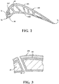
Figure 6 is a schematic partial fragmentary view of a mold with a core formed of a material that includes radiopaque particles for casting of a component according to a non-liming embodiment. -
Figure 1 schematically illustrates a general perspective view of anexemplary component 20, e.g., an actively cooled airfoil segment of a gas turbine engine.Figure 2 is an expanded cross-sectional view of thecomponent 20 along the line 2-2 ofFigure 1 . It should be appreciated that although a particular component type is illustrated in the disclosed non-limiting embodiment, other components, such as blades, vanes, exhaust duct liners, nozzle flaps, and nozzle seals, as well as other actively cooled components will also benefit herefrom. These components, for example, operate in challenging high-temperature environments such as a hot section of a gas turbine engine and have aggressive requirements in terms of durability and temperature allowances. - The
component 20 includes aninternal passage architecture 30. Theinternal passage architecture 30 may include various passages, apertures and features. In this example, thecomponent 20 may be a rotor blade that generally includes aroot section 40, aplatform section 50 and anairfoil section 60. Theairfoil section 60 is defined by an outerairfoil wall surface 68 between a leadingedge 70 and atrailing edge 72, as shown inFigure 2 . The outerairfoil wall surface 68 defines a generally concave shaped portion forming apressure side 68P and a generally convex shaped portion forming asuction side 68S typically shaped for use in a respective stage of a high pressure turbine section. - The outer
airfoil wall surface 68 extends spanwise from theplatform section 50 to atip 74 of theairfoil section 60. Thetrailing edge 72 is spaced chordwise from the leadingedge 70. The airfoil has a multiple of cavities or passages for cooling air as represented by the leadingedge passage 76 andsupply passages root section 40. The passages extend into the interior of theairfoil section 60 and may extend in a serpentine or other non-linear fashion. It should be appreciated that the passage arrangement shown inFigures 1 and2 is merely illustrative and that various passages may alternatively or additionally be provided. - A multiple of internal impingement holes, as represented by the
hole 76P, fluidly connect theleading edge passage 76 in the leading edge region with thesupply passage 80 to receive cooling air from theroot section 40. It should be appreciated that the holes may be of various shapes. A multiple of film cooling holes adjacent the leadingedge 70, as represented by the cooling holes 88, may extend from theleading edge passage 76 through the outerairfoil wall surface 68. The cooling holes 88, film or effusion, may be formed with, for example, lasers, Electron Discharge Machining ("EDM"), water jet, or other techniques. In a non-limiting example, the cooling holes 88 may be approximately 0.014-0.125 inches (0.35-3.2mm) in diameter and may be drilled normal or angled to the outerairfoil wall surface 68. - With further reference to
Figure 3 , the flow path surfaces of thecomponent 20, such as thepressure side 68P and thesuction side 68S (Figure 2 ) of theairfoil section 60 and the associated surfaces of the platforms section 50 (Figure 1 ), may be coated to provide thermal barrier, environmental barrier, and/or other capabilities required to survive in a high-temperature environment. The coating may be a thermal barrier coating that includes abond coat 110 and atop coat 100. Thebond coat 110, in one non-limiting example, may be a nickel-based alloy material which coats thepressure side 68P and thesuction side 68S as well as theinternal passage architecture 30 via immersion application, while thetop coat 100 may be a ceramic material that is applied to thepressure side 68P and thesuction side 68S via a plasma or other spray coating system. In some non-limiting embodiments, thetop coat 100 may be thicker than thebond coat 110. - With reference to
Figure 4 , aremanufacture method 200 in one disclosed non-limiting embodiment to restore thecomponent 20 to near-original capability is shown. It should be appreciated that although a particular remanufacture method is depicted, other manufacture, repair, and/or remanufacture processes and methods will also benefit herefrom. - The
method 200 initially includes preparation of the component 20 (step 202) such as by degreasing, fluoride-ion cleaning, grit blasting, hydrogen furnace cleaning, vacuum cleaning, and/or other processes. It should be appreciated that alternative or additional cleaning and preparation steps to facilitate the method may be performed. - Next, the
top coat 100 may be removed (step 204). The removal or "strip" may be performed by a water jet, grit blast, potassium hydroxide, sodium hydroxide, or other process. Thetop coat 100 and a portion of thebond coat 110 may be removed. That is, thetop coat 100 and thebond coat 110 are typically applied in sprayed layers such that all layers of thetop coat 100 are removed and one or more of the layers ofbond coat 110 may be removed in an area to be remanufactured. Alternatively, the entiretop coat 100 is removed from thebond coat 110. Alternatively, still, thetop coat 100 and thebond coat 110 may be completely removed. - Next, a
material 120 is disposed in theinternal passage architecture 30 of the component (step 206;Figure 5 ). Thematerial 120 may be located in one or more passages such as theleading edge passage 76 or selectively disposed in only those passages that communicate withcooling holes 88 that extend through the outerairfoil wall surface 68. It should be appreciated that thematerial 120 may be utilized to form ceramic cores or other components that may be utilized to initially form theinternal passage architecture 30 via, for example, a lost wax investment casting process as will be further described. In one embodiment, thematerial 120 may be an alumina or silica-base ceramic fill. In another embodiment, thematerial 120 may be a salt-based protective fill that is a water soluble material composed of a salt such as magnesium sulfate, tribasic potassium phosphate, or other such salt-based composition, that, in one specific example, may be a mixture of about 50 mol % of Na2C03, about 20 mol % of NaCl, and about 30 mol % of KCl, which may be typical of a salt core casting material that is often utilized in an investment casting technique using water soluble cores composed of salts in place of the ceramic cores traditionally used in airfoil casting for generating internal cavities. - The salt-based protective fill may be injected into the
internal passage architecture 30 as a slurry substance which hardens when cured. The upper temperature limit of thematerial 120 may be tuned by selection of the salt; for instance, magnesium sulfate will not melt until 2055 °F (1124 °C) and tribasic potassium phosphate will not melt until 2516 °F (1380 °C). While these melting temperatures are below ceramics, they offer a distinct advantage of being highly water-soluble: 255 g/L for magnesium sulfate and 900 g/L for tribasic potassium phosphate at 77 °F (25 °C) (as a reference, NaCl is water soluble at 350 g/L at 77 °F (25 °C)). The water-soluble, high-temperature-capable material 120 protects theinternal passage architecture 30 during cooling hole repair, and facilitates a thermally and geometrically stable substrate for accurate braze repair of cooling holes 88. - Next, the cured
material 120 may be selectively removed from within the holes 88 (step 208). The removal may be performed manually with a pick or other tool. That is, one ormore holes 88 that are incorrectly positioned or otherwise to be filled may be cleaned of thematerial 120. - Next, the
bond coat 110 is removed (step 210) via, for example, a hydrofluoric acid, or other process. Thecomponent 20 is typically dipped into the hydrofluoric acid. As thematerial 120 is disposed in theinternal passage architecture 30, thematerial 120 operates to protect theinternal passage architecture 30 from the hydrofluoric acid. That is, thematerial 120 operates to protect thebond coat 110 within theinternal passage architecture 30. - Next, a nickel braze alloy composition such as an Oxidation Resistant Braze (ORB) composition is then applied to the
component 20 over theholes 88 which are to be filled (step 212). An example of an Oxidation Resistant Braze ("ORB") composition is available under the trademark TURBOFIX. The nickel braze alloy composition is compatible with the nickel based superalloy that forms thecomponent 20 as, in one example, thecomponent 20 is formed of a nickel based superalloy known by the industry specification as a PWA 1455 base alloy. - The nickel braze alloy composition, in one disclosed non-limiting embodiment, includes a combination of: base powder alloy; alloy powder with a melting point depressant such as boron; and a braze binder such as an organic vehicle like cellulose. For example, the nickel braze alloy composition may include 50-80% base powder alloy and 10% braze binder with the remainder as an alloy powder with a melting point depressant. Various other combinations and ingredients may alternatively or additionally be utilized. The water-soluble, high-temperature-
capable material 120 facilitates a thermally and geometrically stable substrate for accurate braze repair. - Next, the ORB may be blended into the substrate (Step 214).
- Next, the
component 20 may be recoated as required to repair the thermal barrier coating (step 216). That is, thebond coat 110 and thetop coat 100 are reapplied as required. The removed layer(s) ofbond coat 110 may be reapplied if necessary to bring the thickness of thebond coat 110 to specification. Thebond coat 110 is relatively thin and reapplication thereof minimally effects, if at all, the cooling holes 88. Thecomponent 20 may then be cleaned and prepped if required to receive thetop coat 100. Thematerial 120, being high temperature resistant, facilitates the prevention of "coat down" in which prior coated holes 88 are undesirably reduced in diameter from their desired diameter in response to the recoating operation. That is, thematerial 120 may be maintained within theinternal passage architecture 30 while thetop coat 100 is applied. - Next, correctly positioned holes are drilled into the
component 20 through the ORB (step 218). One process to form the holes is to laser drill each hole with a laser beam from the exterior of the outerairfoil wall surface 68. Thematerial 120 operates to protect theinternal passage architecture 30 to attenuate the intensity of the laser beam. Thematerial 120 ensures that the laser beam does not inadvertently damage internal surfaces opposite the coolingair hole 88 after the laser beam breaks through the outerairfoil wall surface 68 during the laser drilling process. - The
material 120 further facilitates the protection of features within theinternal passage architecture 30 of acomponent 20 such as a turbine blade that is tuned, in this example, to maintain post-spall metal temperatures to be about 2000 °F (1093 °C). The post-spall metal temperatures difference for which thecomponent 20 remains capable of resisting as compared to a remanufacture for which the features may be compromised are dependent upon the type of cavity and, for example, may be between about 20 °F-200 °F (-6 °C-93 °C) dependent upon the cavity configuration. - Finally, the
material 120 is removed (step 220). The alumina or silica-base ceramic fill may be removed by flushing with a caustic solution. The salt-based protective fill does not require such relatively harsh solvents to remove, which may damage the underlying alloy and coating. In one example, an agitated water rinse is sufficient to remove the salt-based protective fill. - After the
material 120 is removed (step 220), thecomponent 20 may be inspected to ensure that thematerial 120 has been completed removed (step 222). - In one disclosed non-limiting embodiment, the
material 120 includes radiopaque particles 125 (Figure 5 ) that are sufficiently radiopaque to be used with more readily available gamma or X-ray techniques, as compared to N-ray techniques. Theradiopaque particles 125 may include Molybdenum Dioxide (MoO2), Zirconium Dioxide (ZrO2), tungsten trioxide, tantalum pentoxide, molybdenum silicide, tungsten silicide, elemental molybdenum, tantalum, tungsten, and/or other refractory metal particles. - The main factors that contribute to a material's radiopacity are its density and atomic number. Refractory metals have one characteristic in common: an exceptionally high melting point. Although there are twelve refractory metals, only five are widely used: Tungsten, Molybdenum, Niobium, Tantalum and Rhenium. Refractory metal particles may be particularly beneficial as the
radiopaque particles 125 as the refractory metal particles are readily capable of being milled down to desired particle sizes appropriate for typical ceramic injection molding. Refractory metal particles can also readily withstand the temperatures at which thefiller material 120 are fired/sintered after injection to form the ceramic cores. In a non-limiting embodiment, theradiopaque particles 125 may be of particle sizes between about 0.0001 inches to 0.003 inches (0.0025mm - 0.076mm) in diameter. It should be appreciated that radiopaque particles may be sized to be dispersed throughout the material 120 yet be visible in an X-ray or gamma ray image. - The
radiopaque particles 125 may be dispersed within thematerial 120 when disposed in the internal passage architecture 30 (step 206;Figure 4 ) to ensure detection during later inspecting via relatively available gamma or X-ray techniques. In one example, theradiopaque particles 125 may form between about 3-8% of thematerial 120. The quantity ofradiopaque particles 125 may need only be limited to avoid defects in thematerial 120, e.g, that which cause defects to arise in the ceramic injection and firing process, such as, for example, cracking due to complications regarding sintering with other ceramic materials. - The refractory metal particles are highly radiopaque, exhibit virtually no chemical reactivity with agents used in the casting and manufacturing/repair processes, and can withstand temperatures far in excess of the range encountered in superalloy casting and manufacturing/repair processes before melting or decomposing. Being radiopaque, the refractory metal particles increase the bulk attenuation of the
material 120 and thereby increase its ability to be detected via radiographic imaging at gamma/X-ray wavelengths during inspection to confirm thematerial 120 is completely removed without an increase in cost or lead time (step 222;Figure 4 ). - The
radiopaque particles 125 thus permit a film or digital X-ray, possibly a bench-top X-ray, to inspect components forresidual material 120. With the X-ray and refractory metal doped core, any residual material after the removal process (step 220) would appear as a positive metal in the internal cavity. For example, the refractory metal may show up brighter (e.g., thicker material on wall of internal cavity) rather than darker (no material - empty internal cavity) on a gamma or X-ray image. This eliminates the heretofore need to use qualified nuclear reactors to inspect castings (e.g., N-ray inspection), which at times may be a single point of failure and industrial risk. - With reference to
Figure 6 , in another disclosed non-limiting embodiment, while not to be limited to any single method, a casting method may utilize acore 300 at least partially manufactured of the material 120 that includesradiopaque particles 125. Thecore 300 may be used in the manufacturing process of thecomponent 20 to at least partially define theinternal passage architecture 30 therein. That is, thecore 300 is at least partially manufactured of thematerial 120 and may be utilized in an original manufacture type casting process. - The
core 300 may be produced by a molding process using a ceramic slurry and a shaped die. It should be further appreciated that thematerial 120 including theradiopaque particles 125 may be injected, molded, transfer molded, additively manufactured, or otherwise manipulated to form thecore 300. That is, irrespective of manufacture technique, thecore 300 may be at least partially formed of the material 120 that includes theradiopaque particles 125. Theradiopaque particles 125 may be dispersed within thematerial 120 upon manufacture of the core 300 to ensure detection during inspecting via relatively available gamma or X-ray techniques. As theradiopaque particles 125 can be dispersed within thematerial 120 when thecore 300 is first formed, thecore 300 is radiopaque from initial production, which enables inspection at any point in the process yet avoids harsh and toxic tagging chemicals as used in other processes. - The
core 300 provides the geometry desired for theinternal passage architecture 30 and is placed in a die whose walls surround, but are generally spaced away from, thecore 300. The die is filled with a disposable pattern material such as wax, although plastics, low melting-point metals, and organic compounds such as urea, may be employed. The die is removed leaving thecore 300 embedded in the disposable pattern material. - An
outer shell mold 302 is then formed about the disposable pattern material by dipping the pattern in ceramic slurry and then applying larger, dry ceramic particles to the slurry. This process is termed stuccoing. The stuccoed wax pattern that contains thecore 300 is then dried and the stuccoing process repeated to provide the desired wall thickness for theouter shell mold 302. At this point, theouter shell mold 302 is thoroughly dried and heated to an elevated temperature to remove the disposable pattern material, e.g., wax, and strengthen the ceramic material. - The result is a
mold 304 formed by theouter shell mold 302 containing the core 300 therein and defining a mold cavity to cast thecomponent 20. The exterior of thecore 300 defines theinternal passage architecture 30 to be formed in thecast component 20 and the interior of theouter shell mold 302 defines the external dimensions of thecomponent 20. That is, themold 304 operates as a melting unit and/or a die for a desired material that forms thecomponent 20. Thecore 300 andouter shell mold 302 may also define casting portions such as gates and risers which are necessary for the casting process but are not a part of the finished cast component. - After the removal of the wax disposable pattern material and
mold 304 is formed, a molten material is poured into the cavity and solidified. The desired material may include, but not be limited to, a superalloy or other material such as nickel based superalloy, cobalt based superalloy, iron based superalloy, and mixtures and/or alternatives thereof that is melted; a molten superalloy that is then solidified; or other material. Alternatively, or in addition, a single crystal starter seed or grain selector may be utilized to enable a single crystal to form when solidifying the component. During the casting process, thecore 300 fills a selected volume within theouter shell mold 302 that, when removed from the finished casting, defines theinternal passage architecture 30 utilized for cooling airflow within thecomponent 20. - Alternatively, or in addition, the
core 300 may optionally include a Refractory Metal Core (RMC) 500 mounted thereto to form a portion of theinternal passage architecture 30.RMC 500, in some embodiments, can be a metal based sheet with a protective coating. TheRMC 500, in one example, is a sheet with apertures that forms a thin portion of a trailing edge cavity with features formed by the apertures. - The refractory metal of
RMC 500 provides more ductility than conventional ceramic core materials while the coating protects the base metal from alloying with the refractory metal in the investment casting process. TheRMC 500 may be attached to thecore 300 via an adhesive or other attachment mechanism to form a portion of theinternal passage architecture 30 such as that which is contiguous to the trailing edge 72 (Figure 1 ). Following solidification of the material poured intomold 304, theouter shell mold 302 may be broken away and thecore 300, as well as anyoptional RMC 500, may then be removed from the solidifiedcomponent 20 by, for example, caustic leaching or mechanical processes, to form thefinished component 20. It should be appreciate that machining, surface treating, coating or any other desirable finishing operation may further finish thecomponent 20. - During the removal process of the
core 300 and/or theRMC 500, residual from thecore 300 may remain within thecomponent 20. However, as detailed above, theradiopaque particles 125 within thecore 300 permit a film or digital X-ray, possibly a bench-top X-ray, to facilitate inspection of thecomponent 20 forresidual material 120 to confirm complete removal of thecore 300. If residual material is detected, additional removal processes may be performed to ensure a properly finishedcomponent 20. - The use of the terms "a," "an," "the," and similar references in the context of description (especially in the context of the following claims) are to be construed to cover both the singular and the plural, unless otherwise indicated herein or specifically contradicted by context. The modifier "about" used in connection with a quantity is inclusive of the stated value and has the meaning dictated by the context (e.g., it includes the degree of error associated with measurement of the particular quantity). All ranges disclosed herein are inclusive of the endpoints, and the endpoints are independently combinable with each other. It should be appreciated that relative positional terms such as "forward," "aft," "upper," "lower," "above," "below," and the like are with reference to the normal operational attitude of the vehicle and should not be considered otherwise limiting.
- Although the different non-limiting embodiments have specific illustrated components, the embodiments of this invention are not limited to those particular combinations. It is possible to use some of the components or features from any of the non-limiting embodiments in combination with features or components from any of the other non-limiting embodiments.
- It should be appreciated that like reference numerals identify corresponding or similar elements throughout the several drawings. It should also be appreciated that although a particular component arrangement is disclosed in the illustrated embodiment, other arrangements will benefit herefrom.
- Although particular step sequences are shown, described, and claimed, it should be appreciated that steps may be performed in any order, separated or combined unless otherwise indicated and will still benefit from the present disclosure.
- The foregoing description is exemplary rather than defined by the limitations within. Various non-limiting embodiments are disclosed herein, however, one of ordinary skill in the art would recognize that various modifications and variations in light of the above teachings will fall within the scope of the appended claims. It is therefore to be appreciated that within the scope of the appended claims, the disclosure may be practiced other than as specifically described. For that reason the appended claims should be studied to determine true scope and content.
Claims (15)
- A core for use in casting an internal passage architecture of a component, comprising:
a material with radiopaque particles dispersed therein. - The core as recited in claim 1, wherein the radiopaque particles are detectable via radiographic imaging at gamma/x-ray wavelengths.
- The core as recited in claim 1 or 2, wherein the material is a salt-based protective fill material.
- The core as recited in claim 3, wherein the material is a water soluble material, optionally composed of a salt such as magnesium sulfate, tribasic potassium phosphate or a mixture of 50 mol% of Na2C03, 20 mol% of NaCl and 30 mol% of KCl.
- The core as recited in any preceding claim, wherein the radiopaque particles include refractory metal oxide particles.
- The core as recited in any preceding claim, wherein the radiopaque particles include at least one of Molybdenum Dioxide (MoO2), Zirconium Dioxide (ZrO2), tungsten trioxide, tantalum pentoxide, molybdenum silicide, tungsten silicide, elemental molybdenum, tantalum, chromium and tungsten.
- A method of manufacturing a core for casting a component, comprising:
manufacturing a core for at least partially forming an internal passage architecture of a component with a material including radiopaque particles. - The method as recited in claim 7, wherein the material is a salt-based protective fill material.
- The method as recited in claim 7 or 8, wherein the radiopaque particles include refractory metal oxide particles, and/or wherein the radiopaque particles include at least one of Molybdenum Dioxide (MoO2), Zirconium Dioxide (ZrO2), tungsten trioxide, tantalum pentoxide, molybdenum silicide, tungsten silicide, elemental molybdenum, tantalum, chromium and tungsten.
- The method as recited in any of claims 7 to 9, further comprising inspecting the component via radiographic imaging at gamma/X-ray wavelengths to detect residual material subsequent to manufacture of the component.
- The method as recited in any of claims 7 to 10, further comprising attaching a Refractory Metal Core to the core.
- The method as recited in any of claims 7 to 11, wherein the core is produced by a molding process.
- The method as recited in any of claims 7 to 12, wherein the core is transfer molded or is injection molded.
- The method as recited in any of claims 7 to 11, wherein the core is additively manufactured.
- The method as recited in any of claims 7 to 14, further comprising forming an outer shell mold that contains the core, wherein a cavity is formed by the outer shell mold and the core, the cavity defining the component.
Applications Claiming Priority (2)
| Application Number | Priority Date | Filing Date | Title |
|---|---|---|---|
| US14/817,422 US10041890B2 (en) | 2015-08-04 | 2015-08-04 | Radiopaque protective fill for manufacture, repair, or remanufacture of cooled components |
| EP16182883.5A EP3127631B1 (en) | 2015-08-04 | 2016-08-04 | Core with radiopaque material |
Related Parent Applications (1)
| Application Number | Title | Priority Date | Filing Date |
|---|---|---|---|
| EP16182883.5A Division EP3127631B1 (en) | 2015-08-04 | 2016-08-04 | Core with radiopaque material |
Publications (2)
| Publication Number | Publication Date |
|---|---|
| EP3628414A1 true EP3628414A1 (en) | 2020-04-01 |
| EP3628414B1 EP3628414B1 (en) | 2022-09-28 |
Family
ID=56990210
Family Applications (2)
| Application Number | Title | Priority Date | Filing Date |
|---|---|---|---|
| EP19203428.8A Active EP3628414B1 (en) | 2015-08-04 | 2016-08-04 | Method of repairing a cooled component having a misplaced cooling hole |
| EP16182883.5A Active EP3127631B1 (en) | 2015-08-04 | 2016-08-04 | Core with radiopaque material |
Family Applications After (1)
| Application Number | Title | Priority Date | Filing Date |
|---|---|---|---|
| EP16182883.5A Active EP3127631B1 (en) | 2015-08-04 | 2016-08-04 | Core with radiopaque material |
Country Status (2)
| Country | Link |
|---|---|
| US (1) | US10041890B2 (en) |
| EP (2) | EP3628414B1 (en) |
Families Citing this family (7)
| Publication number | Priority date | Publication date | Assignee | Title |
|---|---|---|---|---|
| CN109963685B (en) * | 2016-11-16 | 2022-04-29 | 康明斯有限公司 | System and method for adding material to castings |
| US10702958B2 (en) | 2017-02-22 | 2020-07-07 | General Electric Company | Method of manufacturing turbine airfoil and tip component thereof using ceramic core with witness feature |
| US10625342B2 (en) * | 2017-02-22 | 2020-04-21 | General Electric Company | Method of repairing turbine component |
| US10717130B2 (en) * | 2017-02-22 | 2020-07-21 | General Electric Company | Method of manufacturing turbine airfoil and tip component thereof |
| US11154956B2 (en) | 2017-02-22 | 2021-10-26 | General Electric Company | Method of repairing turbine component using ultra-thin plate |
| US10610933B2 (en) * | 2017-02-22 | 2020-04-07 | General Electric Company | Method of manufacturing turbine airfoil with open tip casting and tip component thereof |
| FR3109108B1 (en) * | 2020-04-09 | 2022-03-11 | Safran | Method for eliminating an area of a layer, turbine blade, turbomachine, aircraft and device |
Citations (5)
| Publication number | Priority date | Publication date | Assignee | Title |
|---|---|---|---|---|
| US4093017A (en) * | 1975-12-29 | 1978-06-06 | Sherwood Refractories, Inc. | Cores for investment casting process |
| US20100288823A1 (en) * | 2008-01-10 | 2010-11-18 | Francis-Jurjen Ladru | Application of Solder to Holes, Coating Processes and Small Solder Rods |
| US20140166255A1 (en) * | 2012-12-19 | 2014-06-19 | United Technologies Corporation | Closure of Cooling Holes with a Filing Agent |
| WO2015009448A1 (en) * | 2013-07-19 | 2015-01-22 | United Technologies Corporation | Additively manufactured core |
| US20150078958A1 (en) * | 2013-09-18 | 2015-03-19 | General Electric Company | Ceramic core compositions, methods for making cores, methods for casting hollow titanium-containing articles, and hollow titanium-containing articles |
Family Cites Families (19)
| Publication number | Priority date | Publication date | Assignee | Title |
|---|---|---|---|---|
| JPS55165252A (en) | 1979-06-09 | 1980-12-23 | Nissan Motor Co Ltd | Resin composition for binding molding sand particle |
| US4799530A (en) * | 1988-02-08 | 1989-01-24 | Precision Castparts Corp. | Method for recovering casting refractory compositions from investment casting slurries |
| US6004683A (en) | 1992-11-04 | 1999-12-21 | C. A. Patents, L.L.C. | Plural layered metal repair tape |
| US5626988A (en) | 1994-05-06 | 1997-05-06 | Battery Technologies Inc. | Sealed rechargeable cells containing mercury-free zinc anodes, and a method of manufacture |
| US6624225B1 (en) | 1996-06-03 | 2003-09-23 | Liburdi Engineering Limited | Wide-gap filler material |
| US5975188A (en) | 1997-10-30 | 1999-11-02 | Howmet Research Corporation | Method of casting with improved detectability of subsurface inclusions |
| US6589600B1 (en) | 1999-06-30 | 2003-07-08 | General Electric Company | Turbine engine component having enhanced heat transfer characteristics and method for forming same |
| US6402866B1 (en) | 1999-09-30 | 2002-06-11 | International Business Machines Corporation | Powdered metallic sheet method for deposition of substrate conductors |
| US6394750B1 (en) | 2000-04-03 | 2002-05-28 | United Technologies Corporation | Method and detail for processing a stator vane |
| US6612480B1 (en) | 2000-11-21 | 2003-09-02 | C.A. Patents, L.L.C. | Method of forming preforms for metal repairs |
| US6909800B2 (en) | 2000-12-15 | 2005-06-21 | United Technologies Corporation | Process and apparatus for locating coated cooling holes on turbine vanes |
| US6503349B2 (en) | 2001-05-15 | 2003-01-07 | United Technologies Corporation | Repair of single crystal nickel based superalloy article |
| US20030106215A1 (en) * | 2001-12-11 | 2003-06-12 | General Electric Company | Turbine nozzle segment and method of repairing same |
| US6913064B2 (en) * | 2003-10-15 | 2005-07-05 | United Technologies Corporation | Refractory metal core |
| US7259350B2 (en) | 2004-08-26 | 2007-08-21 | United Technologies Corporation | Turbine component crack repair using cathodic arc and/or low pressure plasma spraying and HIP |
| US7207374B2 (en) | 2004-10-26 | 2007-04-24 | United Technologies Corporation | Non-oxidizable coating |
| US7966707B2 (en) | 2005-05-06 | 2011-06-28 | United Technologies Corporation | Method for repairing superalloy components using inserts |
| US8394215B2 (en) | 2007-03-22 | 2013-03-12 | United Technologies Corporation | Dual process nickel alloy crack repair |
| EP2559533B1 (en) * | 2008-09-26 | 2020-04-15 | United Technologies Corporation | Casting |
-
2015
- 2015-08-04 US US14/817,422 patent/US10041890B2/en active Active
-
2016
- 2016-08-04 EP EP19203428.8A patent/EP3628414B1/en active Active
- 2016-08-04 EP EP16182883.5A patent/EP3127631B1/en active Active
Patent Citations (5)
| Publication number | Priority date | Publication date | Assignee | Title |
|---|---|---|---|---|
| US4093017A (en) * | 1975-12-29 | 1978-06-06 | Sherwood Refractories, Inc. | Cores for investment casting process |
| US20100288823A1 (en) * | 2008-01-10 | 2010-11-18 | Francis-Jurjen Ladru | Application of Solder to Holes, Coating Processes and Small Solder Rods |
| US20140166255A1 (en) * | 2012-12-19 | 2014-06-19 | United Technologies Corporation | Closure of Cooling Holes with a Filing Agent |
| WO2015009448A1 (en) * | 2013-07-19 | 2015-01-22 | United Technologies Corporation | Additively manufactured core |
| US20150078958A1 (en) * | 2013-09-18 | 2015-03-19 | General Electric Company | Ceramic core compositions, methods for making cores, methods for casting hollow titanium-containing articles, and hollow titanium-containing articles |
Also Published As
| Publication number | Publication date |
|---|---|
| EP3127631A1 (en) | 2017-02-08 |
| US10041890B2 (en) | 2018-08-07 |
| US20170038312A1 (en) | 2017-02-09 |
| EP3127631B1 (en) | 2019-11-06 |
| EP3628414B1 (en) | 2022-09-28 |
Similar Documents
| Publication | Publication Date | Title |
|---|---|---|
| EP3127631B1 (en) | Core with radiopaque material | |
| AU592281B2 (en) | Methods for weld repairing hollow, air cooled turbine blades and vanes | |
| US9518317B2 (en) | Method of coating a component, method of forming cooling holes and a water soluble aperture plug | |
| EP1286020B2 (en) | Method for repairing an apertured gas turbine component | |
| US5972424A (en) | Repair of gas turbine engine component coated with a thermal barrier coating | |
| EP1721697B1 (en) | Superalloy repair methods and inserts | |
| US5813118A (en) | Method for repairing an air cooled turbine engine airfoil | |
| US20050091848A1 (en) | Turbine blade and a method of manufacturing and repairing a turbine blade | |
| US20150037498A1 (en) | Methods and preforms to mask holes and support open-substrate cavities during laser cladding | |
| JP2001115857A (en) | Repair of recess in article surface | |
| EP1584702A1 (en) | Deposition repair of hollow items | |
| EP3156513B1 (en) | Method of coating an article, water soluble plug for preventing hole blockage during coating | |
| US20090194247A1 (en) | Method for repair of a metallic hollow body | |
| US20220212296A1 (en) | System and method for repairing high-temperature gas turbine blades | |
| US10888892B2 (en) | Protecting hole in component during coating process using plug with water soluble layer | |
| WO2011141429A1 (en) | Surface analysis for detecting closed holes and method for reopening | |
| US20140093669A1 (en) | Process for protecting a component, process for laser drilling and component | |
| US20150202702A1 (en) | Gas turbine engine cast structure method for finishing | |
| US20070089675A1 (en) | Device for a coating process, a retort, and a process for internal coating | |
| EP3100819A1 (en) | Repair or remanufacture of cooled components with an oxidation resistant braze | |
| Barhanko et al. | Development of Blade Tip Repair for SGT-700 Turbine Blade Stage 1, With Oxidation Resistant Weld Alloy | |
| US10549338B2 (en) | System and process to provide self-supporting additive manufactured ceramic core | |
| US11795832B2 (en) | System and method for repairing high-temperature gas turbine components |
Legal Events
| Date | Code | Title | Description |
|---|---|---|---|
| PUAI | Public reference made under article 153(3) epc to a published international application that has entered the european phase |
Free format text: ORIGINAL CODE: 0009012 |
|
| STAA | Information on the status of an ep patent application or granted ep patent |
Free format text: STATUS: THE APPLICATION HAS BEEN PUBLISHED |
|
| AC | Divisional application: reference to earlier application |
Ref document number: 3127631 Country of ref document: EP Kind code of ref document: P |
|
| AK | Designated contracting states |
Kind code of ref document: A1 Designated state(s): AL AT BE BG CH CY CZ DE DK EE ES FI FR GB GR HR HU IE IS IT LI LT LU LV MC MK MT NL NO PL PT RO RS SE SI SK SM TR |
|
| STAA | Information on the status of an ep patent application or granted ep patent |
Free format text: STATUS: REQUEST FOR EXAMINATION WAS MADE |
|
| 17P | Request for examination filed |
Effective date: 20201001 |
|
| RBV | Designated contracting states (corrected) |
Designated state(s): AL AT BE BG CH CY CZ DE DK EE ES FI FR GB GR HR HU IE IS IT LI LT LU LV MC MK MT NL NO PL PT RO RS SE SI SK SM TR |
|
| STAA | Information on the status of an ep patent application or granted ep patent |
Free format text: STATUS: EXAMINATION IS IN PROGRESS |
|
| 17Q | First examination report despatched |
Effective date: 20201119 |
|
| RAP1 | Party data changed (applicant data changed or rights of an application transferred) |
Owner name: RAYTHEON TECHNOLOGIES CORPORATION |
|
| GRAP | Despatch of communication of intention to grant a patent |
Free format text: ORIGINAL CODE: EPIDOSNIGR1 |
|
| STAA | Information on the status of an ep patent application or granted ep patent |
Free format text: STATUS: GRANT OF PATENT IS INTENDED |
|
| INTG | Intention to grant announced |
Effective date: 20220408 |
|
| GRAS | Grant fee paid |
Free format text: ORIGINAL CODE: EPIDOSNIGR3 |
|
| GRAA | (expected) grant |
Free format text: ORIGINAL CODE: 0009210 |
|
| STAA | Information on the status of an ep patent application or granted ep patent |
Free format text: STATUS: THE PATENT HAS BEEN GRANTED |
|
| AC | Divisional application: reference to earlier application |
Ref document number: 3127631 Country of ref document: EP Kind code of ref document: P |
|
| AK | Designated contracting states |
Kind code of ref document: B1 Designated state(s): AL AT BE BG CH CY CZ DE DK EE ES FI FR GB GR HR HU IE IS IT LI LT LU LV MC MK MT NL NO PL PT RO RS SE SI SK SM TR |
|
| REG | Reference to a national code |
Ref country code: GB Ref legal event code: FG4D |
|
| RIN1 | Information on inventor provided before grant (corrected) |
Inventor name: CASTLE, LEA DYNNETTE Inventor name: AUXIER, JAMES TISLEY |
|
| REG | Reference to a national code |
Ref country code: CH Ref legal event code: EP |
|
| REG | Reference to a national code |
Ref country code: DE Ref legal event code: R096 Ref document number: 602016075382 Country of ref document: DE |
|
| REG | Reference to a national code |
Ref country code: AT Ref legal event code: REF Ref document number: 1520916 Country of ref document: AT Kind code of ref document: T Effective date: 20221015 |
|
| REG | Reference to a national code |
Ref country code: IE Ref legal event code: FG4D |
|
| REG | Reference to a national code |
Ref country code: LT Ref legal event code: MG9D |
|
| PG25 | Lapsed in a contracting state [announced via postgrant information from national office to epo] |
Ref country code: SE Free format text: LAPSE BECAUSE OF FAILURE TO SUBMIT A TRANSLATION OF THE DESCRIPTION OR TO PAY THE FEE WITHIN THE PRESCRIBED TIME-LIMIT Effective date: 20220928 Ref country code: RS Free format text: LAPSE BECAUSE OF FAILURE TO SUBMIT A TRANSLATION OF THE DESCRIPTION OR TO PAY THE FEE WITHIN THE PRESCRIBED TIME-LIMIT Effective date: 20220928 Ref country code: NO Free format text: LAPSE BECAUSE OF FAILURE TO SUBMIT A TRANSLATION OF THE DESCRIPTION OR TO PAY THE FEE WITHIN THE PRESCRIBED TIME-LIMIT Effective date: 20221228 Ref country code: LV Free format text: LAPSE BECAUSE OF FAILURE TO SUBMIT A TRANSLATION OF THE DESCRIPTION OR TO PAY THE FEE WITHIN THE PRESCRIBED TIME-LIMIT Effective date: 20220928 Ref country code: LT Free format text: LAPSE BECAUSE OF FAILURE TO SUBMIT A TRANSLATION OF THE DESCRIPTION OR TO PAY THE FEE WITHIN THE PRESCRIBED TIME-LIMIT Effective date: 20220928 Ref country code: FI Free format text: LAPSE BECAUSE OF FAILURE TO SUBMIT A TRANSLATION OF THE DESCRIPTION OR TO PAY THE FEE WITHIN THE PRESCRIBED TIME-LIMIT Effective date: 20220928 |
|
| REG | Reference to a national code |
Ref country code: NL Ref legal event code: MP Effective date: 20220928 |
|
| REG | Reference to a national code |
Ref country code: AT Ref legal event code: MK05 Ref document number: 1520916 Country of ref document: AT Kind code of ref document: T Effective date: 20220928 |
|
| PG25 | Lapsed in a contracting state [announced via postgrant information from national office to epo] |
Ref country code: HR Free format text: LAPSE BECAUSE OF FAILURE TO SUBMIT A TRANSLATION OF THE DESCRIPTION OR TO PAY THE FEE WITHIN THE PRESCRIBED TIME-LIMIT Effective date: 20220928 Ref country code: GR Free format text: LAPSE BECAUSE OF FAILURE TO SUBMIT A TRANSLATION OF THE DESCRIPTION OR TO PAY THE FEE WITHIN THE PRESCRIBED TIME-LIMIT Effective date: 20221229 |
|
| PG25 | Lapsed in a contracting state [announced via postgrant information from national office to epo] |
Ref country code: SM Free format text: LAPSE BECAUSE OF FAILURE TO SUBMIT A TRANSLATION OF THE DESCRIPTION OR TO PAY THE FEE WITHIN THE PRESCRIBED TIME-LIMIT Effective date: 20220928 Ref country code: RO Free format text: LAPSE BECAUSE OF FAILURE TO SUBMIT A TRANSLATION OF THE DESCRIPTION OR TO PAY THE FEE WITHIN THE PRESCRIBED TIME-LIMIT Effective date: 20220928 Ref country code: PT Free format text: LAPSE BECAUSE OF FAILURE TO SUBMIT A TRANSLATION OF THE DESCRIPTION OR TO PAY THE FEE WITHIN THE PRESCRIBED TIME-LIMIT Effective date: 20230130 Ref country code: ES Free format text: LAPSE BECAUSE OF FAILURE TO SUBMIT A TRANSLATION OF THE DESCRIPTION OR TO PAY THE FEE WITHIN THE PRESCRIBED TIME-LIMIT Effective date: 20220928 Ref country code: CZ Free format text: LAPSE BECAUSE OF FAILURE TO SUBMIT A TRANSLATION OF THE DESCRIPTION OR TO PAY THE FEE WITHIN THE PRESCRIBED TIME-LIMIT Effective date: 20220928 Ref country code: AT Free format text: LAPSE BECAUSE OF FAILURE TO SUBMIT A TRANSLATION OF THE DESCRIPTION OR TO PAY THE FEE WITHIN THE PRESCRIBED TIME-LIMIT Effective date: 20220928 |
|
| PG25 | Lapsed in a contracting state [announced via postgrant information from national office to epo] |
Ref country code: SK Free format text: LAPSE BECAUSE OF FAILURE TO SUBMIT A TRANSLATION OF THE DESCRIPTION OR TO PAY THE FEE WITHIN THE PRESCRIBED TIME-LIMIT Effective date: 20220928 Ref country code: PL Free format text: LAPSE BECAUSE OF FAILURE TO SUBMIT A TRANSLATION OF THE DESCRIPTION OR TO PAY THE FEE WITHIN THE PRESCRIBED TIME-LIMIT Effective date: 20220928 Ref country code: IS Free format text: LAPSE BECAUSE OF FAILURE TO SUBMIT A TRANSLATION OF THE DESCRIPTION OR TO PAY THE FEE WITHIN THE PRESCRIBED TIME-LIMIT Effective date: 20230128 Ref country code: EE Free format text: LAPSE BECAUSE OF FAILURE TO SUBMIT A TRANSLATION OF THE DESCRIPTION OR TO PAY THE FEE WITHIN THE PRESCRIBED TIME-LIMIT Effective date: 20220928 |
|
| P01 | Opt-out of the competence of the unified patent court (upc) registered |
Effective date: 20230521 |
|
| REG | Reference to a national code |
Ref country code: DE Ref legal event code: R097 Ref document number: 602016075382 Country of ref document: DE |
|
| PG25 | Lapsed in a contracting state [announced via postgrant information from national office to epo] |
Ref country code: NL Free format text: LAPSE BECAUSE OF FAILURE TO SUBMIT A TRANSLATION OF THE DESCRIPTION OR TO PAY THE FEE WITHIN THE PRESCRIBED TIME-LIMIT Effective date: 20220928 Ref country code: AL Free format text: LAPSE BECAUSE OF FAILURE TO SUBMIT A TRANSLATION OF THE DESCRIPTION OR TO PAY THE FEE WITHIN THE PRESCRIBED TIME-LIMIT Effective date: 20220928 |
|
| PG25 | Lapsed in a contracting state [announced via postgrant information from national office to epo] |
Ref country code: DK Free format text: LAPSE BECAUSE OF FAILURE TO SUBMIT A TRANSLATION OF THE DESCRIPTION OR TO PAY THE FEE WITHIN THE PRESCRIBED TIME-LIMIT Effective date: 20220928 |
|
| PLBE | No opposition filed within time limit |
Free format text: ORIGINAL CODE: 0009261 |
|
| STAA | Information on the status of an ep patent application or granted ep patent |
Free format text: STATUS: NO OPPOSITION FILED WITHIN TIME LIMIT |
|
| 26N | No opposition filed |
Effective date: 20230629 |
|
| PGFP | Annual fee paid to national office [announced via postgrant information from national office to epo] |
Ref country code: GB Payment date: 20230720 Year of fee payment: 8 |
|
| PG25 | Lapsed in a contracting state [announced via postgrant information from national office to epo] |
Ref country code: SI Free format text: LAPSE BECAUSE OF FAILURE TO SUBMIT A TRANSLATION OF THE DESCRIPTION OR TO PAY THE FEE WITHIN THE PRESCRIBED TIME-LIMIT Effective date: 20220928 |
|
| PGFP | Annual fee paid to national office [announced via postgrant information from national office to epo] |
Ref country code: FR Payment date: 20230720 Year of fee payment: 8 Ref country code: DE Payment date: 20230720 Year of fee payment: 8 |
|
| PG25 | Lapsed in a contracting state [announced via postgrant information from national office to epo] |
Ref country code: MC Free format text: LAPSE BECAUSE OF FAILURE TO SUBMIT A TRANSLATION OF THE DESCRIPTION OR TO PAY THE FEE WITHIN THE PRESCRIBED TIME-LIMIT Effective date: 20220928 |
|
| REG | Reference to a national code |
Ref country code: CH Ref legal event code: PL |
|
| PG25 | Lapsed in a contracting state [announced via postgrant information from national office to epo] |
Ref country code: MC Free format text: LAPSE BECAUSE OF FAILURE TO SUBMIT A TRANSLATION OF THE DESCRIPTION OR TO PAY THE FEE WITHIN THE PRESCRIBED TIME-LIMIT Effective date: 20220928 |
|
| PG25 | Lapsed in a contracting state [announced via postgrant information from national office to epo] |
Ref country code: LU Free format text: LAPSE BECAUSE OF NON-PAYMENT OF DUE FEES Effective date: 20230804 |
|
| PG25 | Lapsed in a contracting state [announced via postgrant information from national office to epo] |
Ref country code: LU Free format text: LAPSE BECAUSE OF NON-PAYMENT OF DUE FEES Effective date: 20230804 Ref country code: CH Free format text: LAPSE BECAUSE OF NON-PAYMENT OF DUE FEES Effective date: 20230831 |