EP3628346B1 - Cannula insertion detection - Google Patents
Cannula insertion detection Download PDFInfo
- Publication number
- EP3628346B1 EP3628346B1 EP19210323.2A EP19210323A EP3628346B1 EP 3628346 B1 EP3628346 B1 EP 3628346B1 EP 19210323 A EP19210323 A EP 19210323A EP 3628346 B1 EP3628346 B1 EP 3628346B1
- Authority
- EP
- European Patent Office
- Prior art keywords
- cannula
- catheter
- housing
- probe
- skin
- Prior art date
- Legal status (The legal status is an assumption and is not a legal conclusion. Google has not performed a legal analysis and makes no representation as to the accuracy of the status listed.)
- Active
Links
- 238000003780 insertion Methods 0.000 title claims description 96
- 230000037431 insertion Effects 0.000 title claims description 96
- 238000001514 detection method Methods 0.000 title description 7
- 239000000523 sample Substances 0.000 claims description 45
- 238000002347 injection Methods 0.000 claims description 21
- 239000007924 injection Substances 0.000 claims description 21
- 238000001802 infusion Methods 0.000 claims description 18
- WQZGKKKJIJFFOK-GASJEMHNSA-N Glucose Natural products OC[C@H]1OC(O)[C@H](O)[C@@H](O)[C@@H]1O WQZGKKKJIJFFOK-GASJEMHNSA-N 0.000 claims description 17
- 239000008103 glucose Substances 0.000 claims description 17
- 239000008280 blood Substances 0.000 claims description 12
- 210000004369 blood Anatomy 0.000 claims description 12
- 230000003287 optical effect Effects 0.000 claims description 3
- 230000001960 triggered effect Effects 0.000 claims description 2
- 210000003491 skin Anatomy 0.000 description 55
- 239000003814 drug Substances 0.000 description 16
- 229940079593 drug Drugs 0.000 description 16
- NOESYZHRGYRDHS-UHFFFAOYSA-N insulin Chemical compound N1C(=O)C(NC(=O)C(CCC(N)=O)NC(=O)C(CCC(O)=O)NC(=O)C(C(C)C)NC(=O)C(NC(=O)CN)C(C)CC)CSSCC(C(NC(CO)C(=O)NC(CC(C)C)C(=O)NC(CC=2C=CC(O)=CC=2)C(=O)NC(CCC(N)=O)C(=O)NC(CC(C)C)C(=O)NC(CCC(O)=O)C(=O)NC(CC(N)=O)C(=O)NC(CC=2C=CC(O)=CC=2)C(=O)NC(CSSCC(NC(=O)C(C(C)C)NC(=O)C(CC(C)C)NC(=O)C(CC=2C=CC(O)=CC=2)NC(=O)C(CC(C)C)NC(=O)C(C)NC(=O)C(CCC(O)=O)NC(=O)C(C(C)C)NC(=O)C(CC(C)C)NC(=O)C(CC=2NC=NC=2)NC(=O)C(CO)NC(=O)CNC2=O)C(=O)NCC(=O)NC(CCC(O)=O)C(=O)NC(CCCNC(N)=N)C(=O)NCC(=O)NC(CC=3C=CC=CC=3)C(=O)NC(CC=3C=CC=CC=3)C(=O)NC(CC=3C=CC(O)=CC=3)C(=O)NC(C(C)O)C(=O)N3C(CCC3)C(=O)NC(CCCCN)C(=O)NC(C)C(O)=O)C(=O)NC(CC(N)=O)C(O)=O)=O)NC(=O)C(C(C)CC)NC(=O)C(CO)NC(=O)C(C(C)O)NC(=O)C1CSSCC2NC(=O)C(CC(C)C)NC(=O)C(NC(=O)C(CCC(N)=O)NC(=O)C(CC(N)=O)NC(=O)C(NC(=O)C(N)CC=1C=CC=CC=1)C(C)C)CC1=CN=CN1 NOESYZHRGYRDHS-UHFFFAOYSA-N 0.000 description 10
- 238000007920 subcutaneous administration Methods 0.000 description 9
- 238000012360 testing method Methods 0.000 description 9
- 230000035515 penetration Effects 0.000 description 7
- 230000002093 peripheral effect Effects 0.000 description 7
- 102000004877 Insulin Human genes 0.000 description 5
- 108090001061 Insulin Proteins 0.000 description 5
- 229940125396 insulin Drugs 0.000 description 5
- 238000012544 monitoring process Methods 0.000 description 5
- 206010012601 diabetes mellitus Diseases 0.000 description 4
- 238000012377 drug delivery Methods 0.000 description 3
- 210000001519 tissue Anatomy 0.000 description 3
- 239000004743 Polypropylene Substances 0.000 description 2
- 239000003990 capacitor Substances 0.000 description 2
- 238000005229 chemical vapour deposition Methods 0.000 description 2
- 230000006835 compression Effects 0.000 description 2
- 238000007906 compression Methods 0.000 description 2
- 238000005516 engineering process Methods 0.000 description 2
- 210000003722 extracellular fluid Anatomy 0.000 description 2
- 238000007918 intramuscular administration Methods 0.000 description 2
- 239000000463 material Substances 0.000 description 2
- 238000002483 medication Methods 0.000 description 2
- 239000002184 metal Substances 0.000 description 2
- 238000000623 plasma-assisted chemical vapour deposition Methods 0.000 description 2
- 239000004033 plastic Substances 0.000 description 2
- 229920003023 plastic Polymers 0.000 description 2
- 229920001155 polypropylene Polymers 0.000 description 2
- 229910001220 stainless steel Inorganic materials 0.000 description 2
- 239000010935 stainless steel Substances 0.000 description 2
- 210000001015 abdomen Anatomy 0.000 description 1
- 239000004676 acrylonitrile butadiene styrene Substances 0.000 description 1
- 239000000853 adhesive Substances 0.000 description 1
- 230000001070 adhesive effect Effects 0.000 description 1
- 239000012491 analyte Substances 0.000 description 1
- 238000013459 approach Methods 0.000 description 1
- 230000017531 blood circulation Effects 0.000 description 1
- 239000003153 chemical reaction reagent Substances 0.000 description 1
- 238000012790 confirmation Methods 0.000 description 1
- 230000002596 correlated effect Effects 0.000 description 1
- 230000001419 dependent effect Effects 0.000 description 1
- 230000002500 effect on skin Effects 0.000 description 1
- 239000003792 electrolyte Substances 0.000 description 1
- 210000003780 hair follicle Anatomy 0.000 description 1
- 238000001727 in vivo Methods 0.000 description 1
- 238000009434 installation Methods 0.000 description 1
- 238000005259 measurement Methods 0.000 description 1
- 238000000034 method Methods 0.000 description 1
- 230000000149 penetrating effect Effects 0.000 description 1
- -1 polypropylene Polymers 0.000 description 1
- 238000003825 pressing Methods 0.000 description 1
- 238000000926 separation method Methods 0.000 description 1
- 238000002604 ultrasonography Methods 0.000 description 1
- 230000000007 visual effect Effects 0.000 description 1
Images

Classifications
-
- A—HUMAN NECESSITIES
- A61—MEDICAL OR VETERINARY SCIENCE; HYGIENE
- A61B—DIAGNOSIS; SURGERY; IDENTIFICATION
- A61B5/00—Measuring for diagnostic purposes; Identification of persons
- A61B5/06—Devices, other than using radiation, for detecting or locating foreign bodies ; determining position of probes within or on the body of the patient
- A61B5/061—Determining position of a probe within the body employing means separate from the probe, e.g. sensing internal probe position employing impedance electrodes on the surface of the body
- A61B5/063—Determining position of a probe within the body employing means separate from the probe, e.g. sensing internal probe position employing impedance electrodes on the surface of the body using impedance measurements
-
- A—HUMAN NECESSITIES
- A61—MEDICAL OR VETERINARY SCIENCE; HYGIENE
- A61M—DEVICES FOR INTRODUCING MEDIA INTO, OR ONTO, THE BODY; DEVICES FOR TRANSDUCING BODY MEDIA OR FOR TAKING MEDIA FROM THE BODY; DEVICES FOR PRODUCING OR ENDING SLEEP OR STUPOR
- A61M5/00—Devices for bringing media into the body in a subcutaneous, intra-vascular or intramuscular way; Accessories therefor, e.g. filling or cleaning devices, arm-rests
- A61M5/14—Infusion devices, e.g. infusing by gravity; Blood infusion; Accessories therefor
- A61M5/142—Pressure infusion, e.g. using pumps
- A61M5/14244—Pressure infusion, e.g. using pumps adapted to be carried by the patient, e.g. portable on the body
- A61M5/14248—Pressure infusion, e.g. using pumps adapted to be carried by the patient, e.g. portable on the body of the skin patch type
-
- A—HUMAN NECESSITIES
- A61—MEDICAL OR VETERINARY SCIENCE; HYGIENE
- A61B—DIAGNOSIS; SURGERY; IDENTIFICATION
- A61B17/00—Surgical instruments, devices or methods, e.g. tourniquets
- A61B17/34—Trocars; Puncturing needles
- A61B17/3403—Needle locating or guiding means
-
- A—HUMAN NECESSITIES
- A61—MEDICAL OR VETERINARY SCIENCE; HYGIENE
- A61B—DIAGNOSIS; SURGERY; IDENTIFICATION
- A61B34/00—Computer-aided surgery; Manipulators or robots specially adapted for use in surgery
- A61B34/20—Surgical navigation systems; Devices for tracking or guiding surgical instruments, e.g. for frameless stereotaxis
-
- A—HUMAN NECESSITIES
- A61—MEDICAL OR VETERINARY SCIENCE; HYGIENE
- A61B—DIAGNOSIS; SURGERY; IDENTIFICATION
- A61B5/00—Measuring for diagnostic purposes; Identification of persons
- A61B5/0002—Remote monitoring of patients using telemetry, e.g. transmission of vital signals via a communication network
- A61B5/0004—Remote monitoring of patients using telemetry, e.g. transmission of vital signals via a communication network characterised by the type of physiological signal transmitted
-
- A—HUMAN NECESSITIES
- A61—MEDICAL OR VETERINARY SCIENCE; HYGIENE
- A61B—DIAGNOSIS; SURGERY; IDENTIFICATION
- A61B5/00—Measuring for diagnostic purposes; Identification of persons
- A61B5/05—Detecting, measuring or recording for diagnosis by means of electric currents or magnetic fields; Measuring using microwaves or radio waves
- A61B5/053—Measuring electrical impedance or conductance of a portion of the body
- A61B5/0531—Measuring skin impedance
-
- A—HUMAN NECESSITIES
- A61—MEDICAL OR VETERINARY SCIENCE; HYGIENE
- A61B—DIAGNOSIS; SURGERY; IDENTIFICATION
- A61B5/00—Measuring for diagnostic purposes; Identification of persons
- A61B5/145—Measuring characteristics of blood in vivo, e.g. gas concentration, pH value; Measuring characteristics of body fluids or tissues, e.g. interstitial fluid, cerebral tissue
- A61B5/14503—Measuring characteristics of blood in vivo, e.g. gas concentration, pH value; Measuring characteristics of body fluids or tissues, e.g. interstitial fluid, cerebral tissue invasive, e.g. introduced into the body by a catheter or needle or using implanted sensors
-
- A—HUMAN NECESSITIES
- A61—MEDICAL OR VETERINARY SCIENCE; HYGIENE
- A61B—DIAGNOSIS; SURGERY; IDENTIFICATION
- A61B5/00—Measuring for diagnostic purposes; Identification of persons
- A61B5/145—Measuring characteristics of blood in vivo, e.g. gas concentration, pH value; Measuring characteristics of body fluids or tissues, e.g. interstitial fluid, cerebral tissue
- A61B5/14532—Measuring characteristics of blood in vivo, e.g. gas concentration, pH value; Measuring characteristics of body fluids or tissues, e.g. interstitial fluid, cerebral tissue for measuring glucose, e.g. by tissue impedance measurement
-
- A—HUMAN NECESSITIES
- A61—MEDICAL OR VETERINARY SCIENCE; HYGIENE
- A61B—DIAGNOSIS; SURGERY; IDENTIFICATION
- A61B5/00—Measuring for diagnostic purposes; Identification of persons
- A61B5/145—Measuring characteristics of blood in vivo, e.g. gas concentration, pH value; Measuring characteristics of body fluids or tissues, e.g. interstitial fluid, cerebral tissue
- A61B5/1468—Measuring characteristics of blood in vivo, e.g. gas concentration, pH value; Measuring characteristics of body fluids or tissues, e.g. interstitial fluid, cerebral tissue using chemical or electrochemical methods, e.g. by polarographic means
- A61B5/1473—Measuring characteristics of blood in vivo, e.g. gas concentration, pH value; Measuring characteristics of body fluids or tissues, e.g. interstitial fluid, cerebral tissue using chemical or electrochemical methods, e.g. by polarographic means invasive, e.g. introduced into the body by a catheter
- A61B5/14735—Measuring characteristics of blood in vivo, e.g. gas concentration, pH value; Measuring characteristics of body fluids or tissues, e.g. interstitial fluid, cerebral tissue using chemical or electrochemical methods, e.g. by polarographic means invasive, e.g. introduced into the body by a catheter comprising an immobilised reagent
-
- A—HUMAN NECESSITIES
- A61—MEDICAL OR VETERINARY SCIENCE; HYGIENE
- A61B—DIAGNOSIS; SURGERY; IDENTIFICATION
- A61B5/00—Measuring for diagnostic purposes; Identification of persons
- A61B5/15—Devices for taking samples of blood
- A61B5/151—Devices specially adapted for taking samples of capillary blood, e.g. by lancets, needles or blades
- A61B5/15101—Details
- A61B5/15103—Piercing procedure
- A61B5/15107—Piercing being assisted by a triggering mechanism
- A61B5/15109—Fully automatically triggered, i.e. the triggering does not require a deliberate action by the user, e.g. by contact with the patient's skin
-
- A—HUMAN NECESSITIES
- A61—MEDICAL OR VETERINARY SCIENCE; HYGIENE
- A61B—DIAGNOSIS; SURGERY; IDENTIFICATION
- A61B5/00—Measuring for diagnostic purposes; Identification of persons
- A61B5/15—Devices for taking samples of blood
- A61B5/157—Devices characterised by integrated means for measuring characteristics of blood
-
- A—HUMAN NECESSITIES
- A61—MEDICAL OR VETERINARY SCIENCE; HYGIENE
- A61B—DIAGNOSIS; SURGERY; IDENTIFICATION
- A61B5/00—Measuring for diagnostic purposes; Identification of persons
- A61B5/68—Arrangements of detecting, measuring or recording means, e.g. sensors, in relation to patient
- A61B5/6846—Arrangements of detecting, measuring or recording means, e.g. sensors, in relation to patient specially adapted to be brought in contact with an internal body part, i.e. invasive
- A61B5/6847—Arrangements of detecting, measuring or recording means, e.g. sensors, in relation to patient specially adapted to be brought in contact with an internal body part, i.e. invasive mounted on an invasive device
- A61B5/6848—Needles
-
- A—HUMAN NECESSITIES
- A61—MEDICAL OR VETERINARY SCIENCE; HYGIENE
- A61B—DIAGNOSIS; SURGERY; IDENTIFICATION
- A61B5/00—Measuring for diagnostic purposes; Identification of persons
- A61B5/68—Arrangements of detecting, measuring or recording means, e.g. sensors, in relation to patient
- A61B5/6846—Arrangements of detecting, measuring or recording means, e.g. sensors, in relation to patient specially adapted to be brought in contact with an internal body part, i.e. invasive
- A61B5/6847—Arrangements of detecting, measuring or recording means, e.g. sensors, in relation to patient specially adapted to be brought in contact with an internal body part, i.e. invasive mounted on an invasive device
- A61B5/6852—Catheters
-
- A—HUMAN NECESSITIES
- A61—MEDICAL OR VETERINARY SCIENCE; HYGIENE
- A61B—DIAGNOSIS; SURGERY; IDENTIFICATION
- A61B5/00—Measuring for diagnostic purposes; Identification of persons
- A61B5/74—Details of notification to user or communication with user or patient ; user input means
- A61B5/742—Details of notification to user or communication with user or patient ; user input means using visual displays
-
- A—HUMAN NECESSITIES
- A61—MEDICAL OR VETERINARY SCIENCE; HYGIENE
- A61B—DIAGNOSIS; SURGERY; IDENTIFICATION
- A61B5/00—Measuring for diagnostic purposes; Identification of persons
- A61B5/74—Details of notification to user or communication with user or patient ; user input means
- A61B5/7455—Details of notification to user or communication with user or patient ; user input means characterised by tactile indication, e.g. vibration or electrical stimulation
-
- A—HUMAN NECESSITIES
- A61—MEDICAL OR VETERINARY SCIENCE; HYGIENE
- A61B—DIAGNOSIS; SURGERY; IDENTIFICATION
- A61B5/00—Measuring for diagnostic purposes; Identification of persons
- A61B5/74—Details of notification to user or communication with user or patient ; user input means
- A61B5/746—Alarms related to a physiological condition, e.g. details of setting alarm thresholds or avoiding false alarms
-
- A—HUMAN NECESSITIES
- A61—MEDICAL OR VETERINARY SCIENCE; HYGIENE
- A61B—DIAGNOSIS; SURGERY; IDENTIFICATION
- A61B90/00—Instruments, implements or accessories specially adapted for surgery or diagnosis and not covered by any of the groups A61B1/00 - A61B50/00, e.g. for luxation treatment or for protecting wound edges
- A61B90/36—Image-producing devices or illumination devices not otherwise provided for
-
- A—HUMAN NECESSITIES
- A61—MEDICAL OR VETERINARY SCIENCE; HYGIENE
- A61B—DIAGNOSIS; SURGERY; IDENTIFICATION
- A61B90/00—Instruments, implements or accessories specially adapted for surgery or diagnosis and not covered by any of the groups A61B1/00 - A61B50/00, e.g. for luxation treatment or for protecting wound edges
- A61B90/39—Markers, e.g. radio-opaque or breast lesions markers
-
- A—HUMAN NECESSITIES
- A61—MEDICAL OR VETERINARY SCIENCE; HYGIENE
- A61M—DEVICES FOR INTRODUCING MEDIA INTO, OR ONTO, THE BODY; DEVICES FOR TRANSDUCING BODY MEDIA OR FOR TAKING MEDIA FROM THE BODY; DEVICES FOR PRODUCING OR ENDING SLEEP OR STUPOR
- A61M25/00—Catheters; Hollow probes
- A61M25/01—Introducing, guiding, advancing, emplacing or holding catheters
- A61M25/0105—Steering means as part of the catheter or advancing means; Markers for positioning
- A61M25/0127—Magnetic means; Magnetic markers
-
- A—HUMAN NECESSITIES
- A61—MEDICAL OR VETERINARY SCIENCE; HYGIENE
- A61M—DEVICES FOR INTRODUCING MEDIA INTO, OR ONTO, THE BODY; DEVICES FOR TRANSDUCING BODY MEDIA OR FOR TAKING MEDIA FROM THE BODY; DEVICES FOR PRODUCING OR ENDING SLEEP OR STUPOR
- A61M5/00—Devices for bringing media into the body in a subcutaneous, intra-vascular or intramuscular way; Accessories therefor, e.g. filling or cleaning devices, arm-rests
- A61M5/14—Infusion devices, e.g. infusing by gravity; Blood infusion; Accessories therefor
- A61M5/158—Needles for infusions; Accessories therefor, e.g. for inserting infusion needles, or for holding them on the body
-
- A—HUMAN NECESSITIES
- A61—MEDICAL OR VETERINARY SCIENCE; HYGIENE
- A61M—DEVICES FOR INTRODUCING MEDIA INTO, OR ONTO, THE BODY; DEVICES FOR TRANSDUCING BODY MEDIA OR FOR TAKING MEDIA FROM THE BODY; DEVICES FOR PRODUCING OR ENDING SLEEP OR STUPOR
- A61M5/00—Devices for bringing media into the body in a subcutaneous, intra-vascular or intramuscular way; Accessories therefor, e.g. filling or cleaning devices, arm-rests
- A61M5/46—Devices for bringing media into the body in a subcutaneous, intra-vascular or intramuscular way; Accessories therefor, e.g. filling or cleaning devices, arm-rests having means for controlling depth of insertion
-
- A—HUMAN NECESSITIES
- A61—MEDICAL OR VETERINARY SCIENCE; HYGIENE
- A61B—DIAGNOSIS; SURGERY; IDENTIFICATION
- A61B34/00—Computer-aided surgery; Manipulators or robots specially adapted for use in surgery
- A61B34/20—Surgical navigation systems; Devices for tracking or guiding surgical instruments, e.g. for frameless stereotaxis
- A61B2034/2046—Tracking techniques
- A61B2034/2055—Optical tracking systems
-
- A—HUMAN NECESSITIES
- A61—MEDICAL OR VETERINARY SCIENCE; HYGIENE
- A61B—DIAGNOSIS; SURGERY; IDENTIFICATION
- A61B90/00—Instruments, implements or accessories specially adapted for surgery or diagnosis and not covered by any of the groups A61B1/00 - A61B50/00, e.g. for luxation treatment or for protecting wound edges
- A61B90/36—Image-producing devices or illumination devices not otherwise provided for
- A61B90/37—Surgical systems with images on a monitor during operation
- A61B2090/373—Surgical systems with images on a monitor during operation using light, e.g. by using optical scanners
-
- A—HUMAN NECESSITIES
- A61—MEDICAL OR VETERINARY SCIENCE; HYGIENE
- A61B—DIAGNOSIS; SURGERY; IDENTIFICATION
- A61B90/00—Instruments, implements or accessories specially adapted for surgery or diagnosis and not covered by any of the groups A61B1/00 - A61B50/00, e.g. for luxation treatment or for protecting wound edges
- A61B90/39—Markers, e.g. radio-opaque or breast lesions markers
- A61B2090/3904—Markers, e.g. radio-opaque or breast lesions markers specially adapted for marking specified tissue
-
- A—HUMAN NECESSITIES
- A61—MEDICAL OR VETERINARY SCIENCE; HYGIENE
- A61B—DIAGNOSIS; SURGERY; IDENTIFICATION
- A61B5/00—Measuring for diagnostic purposes; Identification of persons
- A61B5/0002—Remote monitoring of patients using telemetry, e.g. transmission of vital signals via a communication network
-
- A—HUMAN NECESSITIES
- A61—MEDICAL OR VETERINARY SCIENCE; HYGIENE
- A61B—DIAGNOSIS; SURGERY; IDENTIFICATION
- A61B5/00—Measuring for diagnostic purposes; Identification of persons
- A61B5/06—Devices, other than using radiation, for detecting or locating foreign bodies ; determining position of probes within or on the body of the patient
- A61B5/061—Determining position of a probe within the body employing means separate from the probe, e.g. sensing internal probe position employing impedance electrodes on the surface of the body
- A61B5/062—Determining position of a probe within the body employing means separate from the probe, e.g. sensing internal probe position employing impedance electrodes on the surface of the body using magnetic field
-
- A—HUMAN NECESSITIES
- A61—MEDICAL OR VETERINARY SCIENCE; HYGIENE
- A61B—DIAGNOSIS; SURGERY; IDENTIFICATION
- A61B5/00—Measuring for diagnostic purposes; Identification of persons
- A61B5/74—Details of notification to user or communication with user or patient ; user input means
- A61B5/7405—Details of notification to user or communication with user or patient ; user input means using sound
-
- A—HUMAN NECESSITIES
- A61—MEDICAL OR VETERINARY SCIENCE; HYGIENE
- A61M—DEVICES FOR INTRODUCING MEDIA INTO, OR ONTO, THE BODY; DEVICES FOR TRANSDUCING BODY MEDIA OR FOR TAKING MEDIA FROM THE BODY; DEVICES FOR PRODUCING OR ENDING SLEEP OR STUPOR
- A61M5/00—Devices for bringing media into the body in a subcutaneous, intra-vascular or intramuscular way; Accessories therefor, e.g. filling or cleaning devices, arm-rests
- A61M5/14—Infusion devices, e.g. infusing by gravity; Blood infusion; Accessories therefor
- A61M5/142—Pressure infusion, e.g. using pumps
- A61M5/14244—Pressure infusion, e.g. using pumps adapted to be carried by the patient, e.g. portable on the body
- A61M5/14248—Pressure infusion, e.g. using pumps adapted to be carried by the patient, e.g. portable on the body of the skin patch type
- A61M2005/14252—Pressure infusion, e.g. using pumps adapted to be carried by the patient, e.g. portable on the body of the skin patch type with needle insertion means
-
- A—HUMAN NECESSITIES
- A61—MEDICAL OR VETERINARY SCIENCE; HYGIENE
- A61M—DEVICES FOR INTRODUCING MEDIA INTO, OR ONTO, THE BODY; DEVICES FOR TRANSDUCING BODY MEDIA OR FOR TAKING MEDIA FROM THE BODY; DEVICES FOR PRODUCING OR ENDING SLEEP OR STUPOR
- A61M5/00—Devices for bringing media into the body in a subcutaneous, intra-vascular or intramuscular way; Accessories therefor, e.g. filling or cleaning devices, arm-rests
- A61M5/14—Infusion devices, e.g. infusing by gravity; Blood infusion; Accessories therefor
- A61M5/158—Needles for infusions; Accessories therefor, e.g. for inserting infusion needles, or for holding them on the body
- A61M2005/1585—Needle inserters
-
- A—HUMAN NECESSITIES
- A61—MEDICAL OR VETERINARY SCIENCE; HYGIENE
- A61M—DEVICES FOR INTRODUCING MEDIA INTO, OR ONTO, THE BODY; DEVICES FOR TRANSDUCING BODY MEDIA OR FOR TAKING MEDIA FROM THE BODY; DEVICES FOR PRODUCING OR ENDING SLEEP OR STUPOR
- A61M5/00—Devices for bringing media into the body in a subcutaneous, intra-vascular or intramuscular way; Accessories therefor, e.g. filling or cleaning devices, arm-rests
- A61M5/14—Infusion devices, e.g. infusing by gravity; Blood infusion; Accessories therefor
- A61M5/158—Needles for infusions; Accessories therefor, e.g. for inserting infusion needles, or for holding them on the body
- A61M2005/1588—Needles for infusions; Accessories therefor, e.g. for inserting infusion needles, or for holding them on the body having means for monitoring, controlling or visual inspection, e.g. for patency check, avoiding extravasation
-
- A—HUMAN NECESSITIES
- A61—MEDICAL OR VETERINARY SCIENCE; HYGIENE
- A61M—DEVICES FOR INTRODUCING MEDIA INTO, OR ONTO, THE BODY; DEVICES FOR TRANSDUCING BODY MEDIA OR FOR TAKING MEDIA FROM THE BODY; DEVICES FOR PRODUCING OR ENDING SLEEP OR STUPOR
- A61M5/00—Devices for bringing media into the body in a subcutaneous, intra-vascular or intramuscular way; Accessories therefor, e.g. filling or cleaning devices, arm-rests
- A61M5/178—Syringes
- A61M5/20—Automatic syringes, e.g. with automatically actuated piston rod, with automatic needle injection, filling automatically
- A61M2005/2073—Automatic syringes, e.g. with automatically actuated piston rod, with automatic needle injection, filling automatically preventing premature release, e.g. by making use of a safety lock
- A61M2005/208—Release is possible only when device is pushed against the skin, e.g. using a trigger which is blocked or inactive when the device is not pushed against the skin
-
- A—HUMAN NECESSITIES
- A61—MEDICAL OR VETERINARY SCIENCE; HYGIENE
- A61M—DEVICES FOR INTRODUCING MEDIA INTO, OR ONTO, THE BODY; DEVICES FOR TRANSDUCING BODY MEDIA OR FOR TAKING MEDIA FROM THE BODY; DEVICES FOR PRODUCING OR ENDING SLEEP OR STUPOR
- A61M25/00—Catheters; Hollow probes
- A61M25/01—Introducing, guiding, advancing, emplacing or holding catheters
- A61M25/0105—Steering means as part of the catheter or advancing means; Markers for positioning
- A61M2025/0166—Sensors, electrodes or the like for guiding the catheter to a target zone, e.g. image guided or magnetically guided
-
- A—HUMAN NECESSITIES
- A61—MEDICAL OR VETERINARY SCIENCE; HYGIENE
- A61M—DEVICES FOR INTRODUCING MEDIA INTO, OR ONTO, THE BODY; DEVICES FOR TRANSDUCING BODY MEDIA OR FOR TAKING MEDIA FROM THE BODY; DEVICES FOR PRODUCING OR ENDING SLEEP OR STUPOR
- A61M2205/00—General characteristics of the apparatus
- A61M2205/13—General characteristics of the apparatus with means for the detection of operative contact with patient, e.g. lip sensor
-
- A—HUMAN NECESSITIES
- A61—MEDICAL OR VETERINARY SCIENCE; HYGIENE
- A61M—DEVICES FOR INTRODUCING MEDIA INTO, OR ONTO, THE BODY; DEVICES FOR TRANSDUCING BODY MEDIA OR FOR TAKING MEDIA FROM THE BODY; DEVICES FOR PRODUCING OR ENDING SLEEP OR STUPOR
- A61M2205/00—General characteristics of the apparatus
- A61M2205/33—Controlling, regulating or measuring
- A61M2205/3317—Electromagnetic, inductive or dielectric measuring means
-
- A—HUMAN NECESSITIES
- A61—MEDICAL OR VETERINARY SCIENCE; HYGIENE
- A61M—DEVICES FOR INTRODUCING MEDIA INTO, OR ONTO, THE BODY; DEVICES FOR TRANSDUCING BODY MEDIA OR FOR TAKING MEDIA FROM THE BODY; DEVICES FOR PRODUCING OR ENDING SLEEP OR STUPOR
- A61M2205/00—General characteristics of the apparatus
- A61M2205/58—Means for facilitating use, e.g. by people with impaired vision
- A61M2205/581—Means for facilitating use, e.g. by people with impaired vision by audible feedback
-
- A—HUMAN NECESSITIES
- A61—MEDICAL OR VETERINARY SCIENCE; HYGIENE
- A61M—DEVICES FOR INTRODUCING MEDIA INTO, OR ONTO, THE BODY; DEVICES FOR TRANSDUCING BODY MEDIA OR FOR TAKING MEDIA FROM THE BODY; DEVICES FOR PRODUCING OR ENDING SLEEP OR STUPOR
- A61M2205/00—General characteristics of the apparatus
- A61M2205/58—Means for facilitating use, e.g. by people with impaired vision
- A61M2205/582—Means for facilitating use, e.g. by people with impaired vision by tactile feedback
-
- A—HUMAN NECESSITIES
- A61—MEDICAL OR VETERINARY SCIENCE; HYGIENE
- A61M—DEVICES FOR INTRODUCING MEDIA INTO, OR ONTO, THE BODY; DEVICES FOR TRANSDUCING BODY MEDIA OR FOR TAKING MEDIA FROM THE BODY; DEVICES FOR PRODUCING OR ENDING SLEEP OR STUPOR
- A61M2205/00—General characteristics of the apparatus
- A61M2205/58—Means for facilitating use, e.g. by people with impaired vision
- A61M2205/583—Means for facilitating use, e.g. by people with impaired vision by visual feedback
Definitions
- the invention is in the field of medical devices. Specifically the invention is directed to apparatus for automatically detecting whether a percutaneous medication delivery device such as a cannula or catheter or probe and exemplary a diagnostic device such as a sensor is fully inserted at an insertion site on a user's body.
- a percutaneous medication delivery device such as a cannula or catheter or probe
- exemplary a diagnostic device such as a sensor
- the invention may be used with a blood testing device, such as a blood glucose monitor, or medication delivery device, such as an insulin infusion pump or patch, but is not limited to such devices.
- a blood testing or medication delivery device worn on the body must have a cannula, catheter or probe properly inserted into the patient's skin to operate. Incomplete insertion may result from flexing or tenting of the skin, from incomplete insertion by the user or separation of the device from the body during use. Such devices often do not have a mechanism that enables confirmation that the delivery device is properly inserted.
- U.S. Patent No. 8,475,432 describes a medication delivery device worn on the body having an automated cannula insertion mechanism.
- U.S. Patent No. 8,603,075 describes an electrochemical blood glucose probe which may be part of an apparatus worn on the body to which is referred for its description of sensor/probe technology.
- AU 738 918 B2 discloses an insertion monitor with a spring-biased collar.
- Percutaneous injections may be performed in the intradermal (ID) region, the subcutaneous (SC) region and the intramuscular (IM) region.
- ID intradermal
- SC subcutaneous
- IM intramuscular
- the SC region is preferred for administering an injection because of the blood flow through the fatty layer of the subcutaneous region. See, for example, Lo Presti, et al., Skin and subcutaneous thickness at injecting sites in children with diabetes: ultrasound findings and recommendations for giving injection, Pediatric Diabetes (2012 ).
- an injection may also be administered into the dermal layer.
- Many medication delivery devices cannot reliably ensure delivery to the SC region because of improper insertion.
- the tip of the device may fail to reach the desired SC space after insertion.
- In-vivo monitoring of blood glucose levels and the like is typically done using probes attached to an on body sensor (OBS) attached to a cannula, catheter or a probe, worn on the user's body and inserted into the user's skin at an insertion site.
- OBS on body sensor
- the ability of the probe to detect in the region of interest is greatly enabled or disabled by the ability of the user to place it in the intended location. Inserting and maintaining the probe in the desired location can often be unreliable, and users are likely to use different practices which adds to the unreliability. Installation often requires two-handed operation and can cause discomfort.
- the different commercially available systems for the automatic delivery of medication such as insulin patch pumps and infusion sets, in which a cannula is required to be inserted for continuous drug delivery, generally lack simple and reliable device feedback when the cannula is incorrectly inserted or seated at the insertion point.
- one object of the invention is to provide an injection depth sensor in a device where the cannula, catheter or probe is worn on the body. Another object of the invention is to ensure that a cannula, catheter or probe reaches the proper insertion depth. A further object of the invention is to provide a simpler mechanism for reliable insertion and detection of a cannula, catheter or probe.
- the invention is defined in the claims.
- an insertion monitor comprising a housing having a top and a base adapted to be positioned adjacent an insertion site on a subject's skin.
- the cannula, catheter or probe as the case may be, has a distal end with a bevel adapted for insertion into a subject's skin, and a proximal end within the housing.
- a pair of electrical contacts in a central area of the base of the housing proximate the cannula, catheter or probe contact the subject's skin when the cannula, catheter or probe has reached full penetration depth.
- a sensor circuit including the pair of electrical contacts detects a change in an electrical property in the sensor circuit when the electrical contacts make contact with the subject's skin, and when contact is interrupted, which triggers an alert mechanism responsive to the change in electrical property to provide indication of the cannula insertion status.
- an insertion monitor which provides sensors on opposite sides of the cannula, catheter or probe to detect whether the cannula, catheter or probe is oriented at an angle at the injection site, which can detect or prevent improper insertion. Additional sensors (i.e., a total of three, four or more sensors) may be used to determine whether angled insertion has occurred, and the sensors need not be positioned opposite each other to make a determination regarding insertion status.
- an insertion monitor utilizes a pair of mechanical posts as the insertion indicator mechanism.
- the example comprises a housing having a top and a base adapted to be positioned on a subject's skin adjacent an insertion site.
- the cannula, catheter or probe has a distal end with a bevel adapted for insertion into the subject's skin protruding distally from the base and a proximal end within the housing.
- At least a pair of mechanical posts is provided having a respective distal end protruding distally from the base in a central area of the base proximate the cannula, catheter or probe, and a respective proximal end within the housing.
- the posts traveling proximally within the housing in correspondence with insertion of the cannula into the subject's skin provides an indication of the cannula, catheter or probe insertion status.
- the indication may be a signal transmitted to remote device, such as a monitor or medication delivery device, or a visible, audible and/or tactile indication on the device housing.
- remote device may include a smart phone, or tablet, or the like.
- remote medication source is also understood to include a conventional tube pump controller and a wireless pump controller.
- a pair of mechanical posts is provided on opposite sides of the cannula, catheter or probe, and an indication of angled insertion is generated when one of the pair of mechanical posts moves a greater distance proximally in the housing than the other of the pair.
- An insertion monitor may utilize a spring loaded collar received in the device housing and surrounding the cannula, catheter or probe.
- the invention comprises a housing adapted to be positioned on a subject's skin adjacent an insertion site, having a recess receiving a spring loaded collar surrounding a cannula, catheter or probe.
- the cannula, catheter, or probe has a distal end with a bevel and a proximal end.
- the spring loaded collar comprises a collar surrounding the cannula, catheter or probe, and a spring positioned between the recess in the housing and the collar.
- a sensor detects when the spring loaded collar is seated fully in the recess in the housing with a distal surface of the collar in a plane with the distal surface of the housing and triggers an alert mechanism indicating the insertion status.
- one or more electrodes is placed on the cannula itself to detect an electrical property of the subject's tissue at the injection site to monitor injection status. This may involve two electrodes positioned on an insulating layer on the cannula, detecting current between the electrodes or other electrical property. Alternatively, the cannula itself provides an electrical contact, and another contact is placed on the base of the housing proximate the injection site, as in the first example described above.
- a cannula insertion monitor comprises: a cannula having a distal end with a bevel and a proximal end positioned in a housing, an electrically insulating layer on the cannula, an electrically conductive distal electrode on the insulating layer and an electrically conductive proximal electrode positioned proximally of the distal electrode on the insulating layer.
- the housing is adapted to be positioned against a subject's skin and includes a sensor circuit electrically connected with the distal electrode and the proximal electrode to detect a change in electrical property between said distal electrode and said proximal electrode.
- An alert mechanism responsive to the detected change in electrical property provides an indication of insertion status.
- medication delivery includes an infusion pump attached to a patch by tubing, wherein the patch is attached to the user's body via a plastic catheter.
- Plastic catheters for infusion often have insertion needles within, where the cutting bevel is located. In that case, the invention is used to ensure that the catheter is properly seated.
- an infusion device may insert a metal cannula directly into the skin for medication delivery, without using a catheter.
- a sensing device for blood testing may utilize a catheter to enclose a probe (in which case the insertion monitor detects the insertion status of the catheter), or a probe may be inserted directly into the skin (in which case the insertion monitor detects the insertion status of the probe itself).
- Many glucose monitoring sensors have an insertion needle (called an "over-needle”) that provides the cutting bevel; the over needle is withdrawn from the patient after the initial incision.
- the insertion detection provides the user with an indication that the sensor or probe is properly inserted and ready to perform its function.
- disclosure relating to insertion detection for a "cannula” is understood to apply equally well to a catheter or probe.
- the distal direction is in the direction of the cannula insertion
- the "proximal direction” is the opposite direction.
- Certain insertion monitors according to the invention provide visible, and/or audible and/or tactile indication of "cannula insertion status," meaning that (i) the cannula is fully inserted and ready for use with an associated device; or (ii) the cannula is not fully inserted and is not ready for use.
- the monitor may provide an indication of ready status (i), not-ready status (ii), or both (i) and (ii).
- an indication of cannula insertion status may be transmitted to other components within the device, to initiate or stop drug delivery or blood testing, for example, without providing a visible, audible and/or tactile result to the user.
- a "tactile" indication includes a vibration mode.
- the insertion monitor of the invention may be used with any system where a cannula, catheter or probe is inserted into the skin for a period of time, including without limitation, a blood glucose monitor, an insulin infusion set or an on-body infusion pump.
- a blood glucose monitor an insulin infusion set or an on-body infusion pump.
- These systems may have an automatic insertion mechanism on a housing proximate the injection site, which may be activated remotely via the insertion mechanism, or the cannula may be inserted manually by the user.
- a probe may be provided with reagents and electrical contacts for the electrochemical determination of blood glucose, as known in the art.
- FIG. 1 depicts an example of the insertion monitor 100 wherein electrical contacts 110, 112 are provided in an area around central portion 118 of the sensor 100, i.e., proximate cannula 140, which is supported on hub 109.
- base 114 of the housing is positioned flush against the skin when cannula 140 is fully inserted.
- the base may be flexible and provided with adhesive in some example to adhere and conform to the skin.
- Electrical contacts 110 and 112 are positioned close enough to cannula 140 that both contacts 110, 112 touch the subject's skin when cannula 140 is inserted, but fail to make contact when the skin is tented.
- Tenting of the skin may occur when cannula 140 pushes the skin distally instead of penetrating fully into the targeted subcutaneous space, as may result when the cannula or catheter, as the case may be, encounters a local hard area of skin or hair follicle for example.
- tenting creates an area of skin adjacent the cannula not in contact with the base of the device.
- contacts 110 and 112 should register a contact failure.
- the contacts may be located substantially adjacent the cannula or catheter as the case may be, up to a distance of about 12 mm.
- a distance greater than 12 mm fails to register the likelihood of a shallow injection due to insufficient penetration depth of the cannula due to tenting.
- a cannula is shown in FIG. 1 , but the person of ordinary skill in the art will appreciate that many catheters for infusion have insertion needles within, in which case the insertion monitor would typically be provided with respect to the catheter, to provide insertion status of the catheter.
- the sensor circuit detects a change in electrical property in the sensor circuit 116, typically an increase in capacitance.
- Touch sensitive devices are known in the art in which an electrode in the device acts as the charge plate of a capacitor, and when a user's body is brought into proximity with the electrode, a virtual capacitor is formed, with the body acting as the second capacitor plate.
- Capacitance may be measured using a capacitance-to-digital converter (CDC).
- CDC capacitance-to-digital converter
- an electrical property such as resistance, impedance or conductivity, could be measured to determine whether proper contact is made between the electrodes 110, 112 and the skin at the injection site.
- an electrical property may be measured in two ways, where the skin is directly contacted, and where sensing electrodes approach but do not touch the skin. A capacitance change can be measured without skin contact, whereas measuring a change in resistance requires skin contact.
- additional electrode point sensors may be included proximate the area of the insertion.
- Sensor circuit 116 generates a signal in response to the change in electrical property which is transmitted to alert mechanism 120, which may be in the form of one or more visible lights, such as light emitting diode (LED) 122, one or more audible alarms 124, or a combination of LED and audible alarm.
- Alert mechanism 120 may create a sensible vibration.
- the sensor circuit 116 may provide the indication of cannula insertion status to a remote testing or delivery device.
- an interruption in skin contact causes a different signal to be transmitted by the sensor circuit, communicating to the user, or to the device, that cannula insertion is in a failure condition.
- a red LED indicates that the cannula is not properly inserted
- a green LED indicates that the cannula is properly inserted.
- cannula insertion status may be transmitted to a peripheral device such as a blood glucose monitor or infusion pump.
- Angled insertion of a cannula, catheter or probe is undesirable because the tip of the cannula, catheter or probe may not reach the desired subcutaneous space.
- the insertion monitor having two contacts proximate the injection site permits detection of angled insertion. For example, when one of the pair of electrical contacts is in contact with the subject's skin and the other is not, the monitor may trigger an alert mechanism to indicate angled insertion. This will prompt the user to fix the angle or prompt a peripheral device to appropriate action, such as stopping infusion or testing.
- FIG. 2A and FIG. 2B A further example is shown in FIG. 2A and FIG. 2B , wherein at least a pair of mechanical posts 230, 232 is positioned proximate cannula 240, on opposite sides of cannula 240.
- the posts are preferably located at a distance of less than 12 mm from the cannula, catheter or probe, as the case may be, to prevent the device registering as fully inserted when skin 201 at the injection site is tented away from base 214 of housing 208.
- Posts 230, 232 move proximally in housing 208 as cannula 240 is inserted.
- the cannula (or catheter as the case may be) may be inserted by pressing the housing against the insertion site or by providing an automated insertion mechanism, as is also practiced in the diabetes care art.
- insertion monitor 200 comprises base 214 and top 208.
- Cannula 240 is supported in hub 209 and has a beveled end protruding distally from base 214 for insertion into a subject's skin.
- Posts 230, 232 protrude from base 214 as housing 208 is placed in position, and when base 214 is flush against the skin, the posts are preferably arranged so that the distal surfaces of posts 230, 232 are flush with base 214. As cannula 240 is inserted into the skin, the posts travel proximally within the housing in correspondence with insertion of the cannula. This proximal movement of posts 230, 232 is controlled by the engagement of posts 230, 232 in hub 209, as well as by movement of housing 208 and base 214 toward the injection site.
- posts 230, 232 are made of rigid material, such as metal or molded polypropylene (PP), or molded acrylonitrile butadiene styrene (ABS) so that the posts move proximally toward the top of the housing as the base becomes situated adjacent the skin.
- base 214 may be made flexible to conform to a wearer's body, posts 230, 232 maintain a vertical position, parallel to the cannula, as a result of engagement with hub 209.
- posts 230, 232 When cannula 240 reaches full insertion depth, the proximal ends of posts 230, 232 are visible through windows 224, 226 in the top of the housing.
- mechanical posts 230, 232 may make contact with respective surfaces 225, 227 in the housing when the cannula reaches full penetration depth.
- Surfaces 225, 227 may be electrical contacts which may close one or more circuits in sensor circuit 216 to generate an alert mechanism indicating that cannula 214 is at full penetration depth, transmitted visibly or audibly to the user or generating an electronic signal to a peripheral device such as a glucose monitor or infusion pump.
- contacts 234, 236 may cause a polymeric color change material to undergo a visible color change to provide indication through windows 224, 226 that cannula 240 has reached full penetration depth.
- contacts 234, 236 may cause a polymeric color change material to undergo a visible color change to provide indication through windows 224, 226 that cannula 240 has reached full penetration depth.
- contact is interrupted between the surface in the housing and the posts, and a different audible or visual indication may be generated to alert the user.
- information may be transmitted to peripheral components of the system, for example, to stop an infusion (in the context of a pump or patch having a remote component), or to stop testing (in the context of a remotely located glucose monitor or infusion pump).
- this may indicate an angled insertion status, which may be used to generate a visible and/or audible alert using LEDs 229 or audible alarm 223, or may be used to generate a signal transmitted to a remote device indicating a likely angled insertion status.
- posts 230, 232 provide a tactile indication for the user that the cannula has reached full penetration depth. This is particularly useful, for example, if the housing 208 is positioned out of sight, on a back portion of the abdomen, for example. In this example, posts 230, 232 protrude from the top of the housing 208 through windows 224, 226 and the user can feel the protruding tips to ensure that the cannula is fully seated at the insertion site. Stops 219 are provided to engage posts 230, 232 in hub 209 to control movement of the posts and prevent posts 230, 232 from separating from hub 209.
- FIG. 3A, FIG. 3B and FIG. 3C An embodiment of the invention is depicted in FIG. 3A, FIG. 3B and FIG. 3C , to detect whether a cannula, catheter or probe is inserted to its full depth with respect to the surface of the skin.
- the device of this embodiment may be used to alert a continuous glucose monitor (CGM) user (or other device user) user to a poorly inserted cannula in the on-body sensor (OBS) (or other device component).
- CGM continuous glucose monitor
- OBS on-body sensor
- This embodiment comprises a spring loaded, sliding collar concentric with the cannula such that, before OBS insertion, it protrudes beyond the plane of the bottom of the device.
- the plane of the OBS bottom Upon proper, full depth insertion of the cannula, the plane of the OBS bottom will contact the plane of the skin, pushing the collar into a recessed space in the OBS base.
- an electrical, magnetic, or optical detector detects the occupied state of the recess and delivers a positive signal to a display or to the electronics and software systems of the remote sensor or drug delivery system, as the case may be. If the skin does not fully contact the housing base (as in a state of "tenting", wherein the skin does not return to being flat after cannula penetration), the collar will not occupy the recess and no signal will be generated.
- housing 301 contains a recess 302 which receives collar 320 sliding on cannula 340.
- collar 320 is urged distally under the bias of compression spring 330.
- Cannula 340 is supported in the housing 301, preferably using a hub (not shown), as generally known and understood in the art, and as described in connection with the previous embodiments.
- FIG. 3B depicts the state wherein collar 320 is fully seated in recess 302, so that the distal side of collar 320 is aligned with the distal side of the housing and positioned adjacent the user's skin 303.
- electrical contacts 312 and 314 are closed when the collar is seated in the recess, sending a signal via circuit 310 that the cannula 340 is fully inserted.
- a glucose monitor or infusion pump can receive a signal to commence or restart operation.
- the 'ready" status of cannula insertion may be indicated audibly or visually using LED or audible alarm or combination thereof, as in the previous embodiments.
- an optical or magnetic sensor may be used instead of electrical contacts 312 and 314.
- FIG. 3A depicts a first example in which cannula 340 may not be fully inserted into the injection site.
- compression spring 330 which is used to urge the collar against the user's skin, is fully extended so that collar 320 is not seated in recess 302.
- This state is detected by contacts 312, 314 (or other sensor system), and an alert mechanism is triggered to peripheral user interface devices.
- FIG. 3C depicts a second example similar to FIG. 3A in which a disruption in the plane of the subject's skin caused by tenting results in the failure of the cannula collar 320 to be seated in recess 302.
- the state of cannula insertion in these cases is indicated by an appropriate alert, generated via LED or audible alarm, or by transmitting a signal to a peripheral device, such as a glucose monitor or infusion pump, regarding the "not ready" status of the cannula.
- a peripheral device such as a glucose monitor or infusion pump
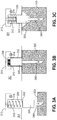
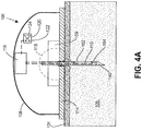
- housing 108 (which could be part of a glucose monitoring on-body sensor, or an infusion set or pump) comprises a base 114 positioned against the user's skin 101 at a site where cannula 140 is to be inserted and cannula 140 is supported on hub 109.
- Cannula 140 is provided with an insulating layer 115, and electrically conductive distal electrode 164 and proximal electrode 162 are positioned on insulating layer 115.
- electrodes 164 and 162 are both within an interstitial space having a generally defined conductivity due to the relatively high concentration of electrolytes in the interstitial fluid.
- a current in sensor circuit 116 flows between the electrodes. If the cannula is not inserted fully, as in FIG. 4B , as when the plane of the skin is distorted due to tenting, for example, then the proximal electrode 162 will not enter the interstitial space 105, and conductivity between the electrodes 162, 164 will be affected in a predictable direction. Likewise, if the cannula is initially properly inserted but is then disturbed, a sudden change in conductivity will occur.
- the status of the circuit detected in the sensor circuit 116 may be transmitted to peripheral user interface devices, for example, triggering an alarm to alert the user that the device is not inserted properly in the skin.
- a signal indicating sufficient conductivity between electrodes 162, 164 may be made a necessary condition for glucose monitoring to commence or restart.
- the insertion monitor may trigger, stop or interrupt medication delivery.
- audible alarm 124 or visible indicator such as LEDs 120 may be used to provide the user with an indication of cannula insertion status.
- Sensor circuit may detect and evaluate an electrical property other than conductivity to obtain information about the status of the cannula insertion. Determining capacitance between electrodes 162, 164, for example, when cannula 140 is fully inserted and not fully inserted may correlate to cannula insertion status.
- the cannula or probe inserted in the subject's tissue is preferably stainless steel.
- the resistive layer 115 and electrode layers 162, 164 may be deposited on the cannula by means known in the art, including chemical vapor deposition (CVD), plasma enhanced chemical vapor deposition (PECVD), printing, and like methods.
- the cannula may be rolled or brushed with resistive ink, leaving a selected area near the bevel conductively exposed to the subject's body.
- Cannula 140 can then be paired with another electrode on housing 108 and an electrical property between the electrode on the housing and cannula 140 is detected by sensor circuit 116 and correlated with cannula insertion status.
Description
- The invention is in the field of medical devices. Specifically the invention is directed to apparatus for automatically detecting whether a percutaneous medication delivery device such as a cannula or catheter or probe and exemplary a diagnostic device such as a sensor is fully inserted at an insertion site on a user's body. The invention may be used with a blood testing device, such as a blood glucose monitor, or medication delivery device, such as an insulin infusion pump or patch, but is not limited to such devices.
- A blood testing or medication delivery device worn on the body must have a cannula, catheter or probe properly inserted into the patient's skin to operate. Incomplete insertion may result from flexing or tenting of the skin, from incomplete insertion by the user or separation of the device from the body during use. Such devices often do not have a mechanism that enables confirmation that the delivery device is properly inserted.
- As an example of a medication delivery device known in the prior art,
U.S. Patent No. 8,475,432 , describes a medication delivery device worn on the body having an automated cannula insertion mechanism.U.S. Patent No. 8,603,075 describes an electrochemical blood glucose probe which may be part of an apparatus worn on the body to which is referred for its description of sensor/probe technology.AU 738 918 B2 - Percutaneous injections may be performed in the intradermal (ID) region, the subcutaneous (SC) region and the intramuscular (IM) region. For many types of injectable medications, including insulin, the SC region is preferred for administering an injection because of the blood flow through the fatty layer of the subcutaneous region. See, for example, Lo Presti, et al., Skin and subcutaneous thickness at injecting sites in children with diabetes: ultrasound findings and recommendations for giving injection, Pediatric Diabetes (2012). Alternatively, an injection may also be administered into the dermal layer. Many medication delivery devices cannot reliably ensure delivery to the SC region because of improper insertion.
- If a cannula, catheter or probe is oriented at an angle with respect to the user's skin, the tip of the device may fail to reach the desired SC space after insertion.
- In-vivo monitoring of blood glucose levels and the like is typically done using probes attached to an on body sensor (OBS) attached to a cannula, catheter or a probe, worn on the user's body and inserted into the user's skin at an insertion site. The ability of the probe to detect in the region of interest is greatly enabled or disabled by the ability of the user to place it in the intended location. Inserting and maintaining the probe in the desired location can often be unreliable, and users are likely to use different practices which adds to the unreliability. Installation often requires two-handed operation and can cause discomfort. Likewise, the different commercially available systems for the automatic delivery of medication, such as insulin patch pumps and infusion sets, in which a cannula is required to be inserted for continuous drug delivery, generally lack simple and reliable device feedback when the cannula is incorrectly inserted or seated at the insertion point.
- In view of the problems identified in the prior art, one object of the invention is to provide an injection depth sensor in a device where the cannula, catheter or probe is worn on the body. Another object of the invention is to ensure that a cannula, catheter or probe reaches the proper insertion depth. A further object of the invention is to provide a simpler mechanism for reliable insertion and detection of a cannula, catheter or probe. The invention is defined in the claims.
- According to an example not forming part of the invention, disclosed is an insertion monitor, comprising a housing having a top and a base adapted to be positioned adjacent an insertion site on a subject's skin. The cannula, catheter or probe, as the case may be, has a distal end with a bevel adapted for insertion into a subject's skin, and a proximal end within the housing. A pair of electrical contacts in a central area of the base of the housing proximate the cannula, catheter or probe contact the subject's skin when the cannula, catheter or probe has reached full penetration depth. A sensor circuit including the pair of electrical contacts detects a change in an electrical property in the sensor circuit when the electrical contacts make contact with the subject's skin, and when contact is interrupted, which triggers an alert mechanism responsive to the change in electrical property to provide indication of the cannula insertion status.
- In a further aspect according to an example not forming part of the invention, disclosed is an insertion monitor which provides sensors on opposite sides of the cannula, catheter or probe to detect whether the cannula, catheter or probe is oriented at an angle at the injection site, which can detect or prevent improper insertion. Additional sensors (i.e., a total of three, four or more sensors) may be used to determine whether angled insertion has occurred, and the sensors need not be positioned opposite each other to make a determination regarding insertion status.
- In another aspect, an insertion monitor according to an example utilizes a pair of mechanical posts as the insertion indicator mechanism. In this aspect, the example comprises a housing having a top and a base adapted to be positioned on a subject's skin adjacent an insertion site. The cannula, catheter or probe has a distal end with a bevel adapted for insertion into the subject's skin protruding distally from the base and a proximal end within the housing. At least a pair of mechanical posts is provided having a respective distal end protruding distally from the base in a central area of the base proximate the cannula, catheter or probe, and a respective proximal end within the housing. The posts traveling proximally within the housing in correspondence with insertion of the cannula into the subject's skin provides an indication of the cannula, catheter or probe insertion status. The indication may be a signal transmitted to remote device, such as a monitor or medication delivery device, or a visible, audible and/or tactile indication on the device housing. A "remote device" may include a smart phone, or tablet, or the like. A "remote medication source" is also understood to include a conventional tube pump controller and a wireless pump controller.
- In other examples, a pair of mechanical posts is provided on opposite sides of the cannula, catheter or probe, and an indication of angled insertion is generated when one of the pair of mechanical posts moves a greater distance proximally in the housing than the other of the pair.
- An insertion monitor according to the invention may utilize a spring loaded collar received in the device housing and surrounding the cannula, catheter or probe. In this aspect, the invention comprises a housing adapted to be positioned on a subject's skin adjacent an insertion site, having a recess receiving a spring loaded collar surrounding a cannula, catheter or probe. The cannula, catheter, or probe has a distal end with a bevel and a proximal end. The spring loaded collar comprises a collar surrounding the cannula, catheter or probe, and a spring positioned between the recess in the housing and the collar. A sensor detects when the spring loaded collar is seated fully in the recess in the housing with a distal surface of the collar in a plane with the distal surface of the housing and triggers an alert mechanism indicating the insertion status.
- According to an example not forming part of the invention, one or more electrodes is placed on the cannula itself to detect an electrical property of the subject's tissue at the injection site to monitor injection status. This may involve two electrodes positioned on an insulating layer on the cannula, detecting current between the electrodes or other electrical property. Alternatively, the cannula itself provides an electrical contact, and another contact is placed on the base of the housing proximate the injection site, as in the first example described above.
- For example, and not by way of limitation, a cannula insertion monitor according to one of these examples comprises: a cannula having a distal end with a bevel and a proximal end positioned in a housing, an electrically insulating layer on the cannula, an electrically conductive distal electrode on the insulating layer and an electrically conductive proximal electrode positioned proximally of the distal electrode on the insulating layer. The housing is adapted to be positioned against a subject's skin and includes a sensor circuit electrically connected with the distal electrode and the proximal electrode to detect a change in electrical property between said distal electrode and said proximal electrode. An alert mechanism responsive to the detected change in electrical property provides an indication of insertion status.
-
-
FIG. 1 depicts an insertion monitor according to an example wherein electrical contacts at the insertion site are connected to a sensor circuit to monitor whether the cannula is properly inserted. -
FIG. 2A, FIG. 2B, FIG. 2C and FIG 2D depict an insertion monitor according to two other examples, utilizing a pair of mechanical posts proximate the cannula insertion site. -
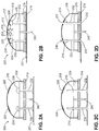
FIG. 3A, FIG. 3B and FIG. 3C depict a cannula insertion monitor according to an embodiment of the invention, utilizing a spring loaded collar surrounding a cannula. -
FIG. 4A andFIG. 4B depict a cannula insertion monitor according to another example, utilizing electrodes on the cannula or catheter itself. - The Figures are schematic only and are not drawn to scale.
- The present invention is useful in any medication delivery, sensing and/or testing application having an inserted or in-dwelling delivery device or probe worn by the user. For example, and not by way of limitation, "medication delivery" includes an infusion pump attached to a patch by tubing, wherein the patch is attached to the user's body via a plastic catheter. Plastic catheters for infusion often have insertion needles within, where the cutting bevel is located. In that case, the invention is used to ensure that the catheter is properly seated. Alternatively, an infusion device may insert a metal cannula directly into the skin for medication delivery, without using a catheter. Similarly, a sensing device for blood testing may utilize a catheter to enclose a probe (in which case the insertion monitor detects the insertion status of the catheter), or a probe may be inserted directly into the skin (in which case the insertion monitor detects the insertion status of the probe itself). Many glucose monitoring sensors have an insertion needle (called an "over-needle") that provides the cutting bevel; the over needle is withdrawn from the patient after the initial incision. In all of these embodiments, the insertion detection provides the user with an indication that the sensor or probe is properly inserted and ready to perform its function. As used herein, disclosure relating to insertion detection for a "cannula" is understood to apply equally well to a catheter or probe.
- As used herein, the "distal" direction is in the direction of the cannula insertion, and the "proximal direction" is the opposite direction. Certain insertion monitors according to the invention provide visible, and/or audible and/or tactile indication of "cannula insertion status," meaning that (i) the cannula is fully inserted and ready for use with an associated device; or (ii) the cannula is not fully inserted and is not ready for use. Depending on the embodiment, the monitor may provide an indication of ready status (i), not-ready status (ii), or both (i) and (ii). Alternatively, or in addition, an indication of cannula insertion status may be transmitted to other components within the device, to initiate or stop drug delivery or blood testing, for example, without providing a visible, audible and/or tactile result to the user. A "tactile" indication includes a vibration mode.
- The insertion monitor of the invention may be used with any system where a cannula, catheter or probe is inserted into the skin for a period of time, including without limitation, a blood glucose monitor, an insulin infusion set or an on-body infusion pump. These systems may have an automatic insertion mechanism on a housing proximate the injection site, which may be activated remotely via the insertion mechanism, or the cannula may be inserted manually by the user. A probe may be provided with reagents and electrical contacts for the electrochemical determination of blood glucose, as known in the art.
-
FIG. 1 depicts an example of theinsertion monitor 100 whereinelectrical contacts central portion 118 of thesensor 100, i.e.,proximate cannula 140, which is supported onhub 109. In this example,base 114 of the housing is positioned flush against the skin whencannula 140 is fully inserted. The base may be flexible and provided with adhesive in some example to adhere and conform to the skin.Electrical contacts contacts cannula 140 is inserted, but fail to make contact when the skin is tented. Tenting of the skin may occur whencannula 140 pushes the skin distally instead of penetrating fully into the targeted subcutaneous space, as may result when the cannula or catheter, as the case may be, encounters a local hard area of skin or hair follicle for example. As shown in the different embodiment ofFIG. 3C , tenting creates an area of skin adjacent the cannula not in contact with the base of the device. When theskin 101 is pushed away frombase 114 of the device,contacts FIG. 1 , but the person of ordinary skill in the art will appreciate that many catheters for infusion have insertion needles within, in which case the insertion monitor would typically be provided with respect to the catheter, to provide insertion status of the catheter. - When both
electrical contacts sensor circuit 116, typically an increase in capacitance. Touch sensitive devices are known in the art in which an electrode in the device acts as the charge plate of a capacitor, and when a user's body is brought into proximity with the electrode, a virtual capacitor is formed, with the body acting as the second capacitor plate. Capacitance may be measured using a capacitance-to-digital converter (CDC). This technology, already being used in the healthcare context, may be readily adapted for use with an injection depth sensor, withelectrical contacts sensor circuit 116 to measure an electrical property that changes when the electrical contacts come into contact with the user's skin. Although described in terms of capacitance, the person of ordinary skill in the art will recognize that the skin has other electrical properties that may be leveraged to make this measurement. Thus, another electrical property, such as resistance, impedance or conductivity, could be measured to determine whether proper contact is made between theelectrodes electrical contacts -
Sensor circuit 116 generates a signal in response to the change in electrical property which is transmitted to alertmechanism 120, which may be in the form of one or more visible lights, such as light emitting diode (LED) 122, one or moreaudible alarms 124, or a combination of LED and audible alarm.Alert mechanism 120 may create a sensible vibration. Alternatively, thesensor circuit 116 may provide the indication of cannula insertion status to a remote testing or delivery device. Likewise, an interruption in skin contact, as may be caused by a change in the skin condition, caused by tenting or flexing for example, or bybase 114 ofhousing 108 pulling away from theskin 101, causes a different signal to be transmitted by the sensor circuit, communicating to the user, or to the device, that cannula insertion is in a failure condition. In a simple example, a red LED indicates that the cannula is not properly inserted, and a green LED indicates that the cannula is properly inserted. Alternatively, or in addition, cannula insertion status may be transmitted to a peripheral device such as a blood glucose monitor or infusion pump. - Angled insertion of a cannula, catheter or probe is undesirable because the tip of the cannula, catheter or probe may not reach the desired subcutaneous space. The insertion monitor having two contacts proximate the injection site permits detection of angled insertion. For example, when one of the pair of electrical contacts is in contact with the subject's skin and the other is not, the monitor may trigger an alert mechanism to indicate angled insertion. This will prompt the user to fix the angle or prompt a peripheral device to appropriate action, such as stopping infusion or testing.
- A further example is shown in
FIG. 2A and FIG. 2B , wherein at least a pair ofmechanical posts proximate cannula 240, on opposite sides ofcannula 240. The posts are preferably located at a distance of less than 12 mm from the cannula, catheter or probe, as the case may be, to prevent the device registering as fully inserted whenskin 201 at the injection site is tented away frombase 214 ofhousing 208. -
Posts housing 208 ascannula 240 is inserted. The cannula (or catheter as the case may be) may be inserted by pressing the housing against the insertion site or by providing an automated insertion mechanism, as is also practiced in the diabetes care art. In the example shown, insertion monitor 200 comprisesbase 214 and top 208.Cannula 240 is supported inhub 209 and has a beveled end protruding distally frombase 214 for insertion into a subject's skin.Posts base 214 ashousing 208 is placed in position, and whenbase 214 is flush against the skin, the posts are preferably arranged so that the distal surfaces ofposts base 214. Ascannula 240 is inserted into the skin, the posts travel proximally within the housing in correspondence with insertion of the cannula. This proximal movement ofposts posts hub 209, as well as by movement ofhousing 208 andbase 214 toward the injection site. For this purpose, posts 230, 232 are made of rigid material, such as metal or molded polypropylene (PP), or molded acrylonitrile butadiene styrene (ABS) so that the posts move proximally toward the top of the housing as the base becomes situated adjacent the skin. Whereasbase 214 may be made flexible to conform to a wearer's body, posts 230, 232 maintain a vertical position, parallel to the cannula, as a result of engagement withhub 209. - When cannula 240 reaches full insertion depth, the proximal ends of
posts windows FIG. 2B ,mechanical posts respective surfaces Surfaces cannula 214 is at full penetration depth, transmitted visibly or audibly to the user or generating an electronic signal to a peripheral device such as a glucose monitor or infusion pump. Alternatively,contacts windows - Where one of the pair of
posts surface alert using LEDs 229 or audible alarm 223, or may be used to generate a signal transmitted to a remote device indicating a likely angled insertion status. - In the example of
FIG. 2C and FIG. 2D , posts 230, 232 provide a tactile indication for the user that the cannula has reached full penetration depth. This is particularly useful, for example, if thehousing 208 is positioned out of sight, on a back portion of the abdomen, for example. In this example, posts 230, 232 protrude from the top of thehousing 208 throughwindows Stops 219 are provided to engageposts hub 209 to control movement of the posts and preventposts hub 209. - An embodiment of the invention is depicted in
FIG. 3A, FIG. 3B and FIG. 3C , to detect whether a cannula, catheter or probe is inserted to its full depth with respect to the surface of the skin. As with the other examples, the device of this embodiment may be used to alert a continuous glucose monitor (CGM) user (or other device user) user to a poorly inserted cannula in the on-body sensor (OBS) (or other device component). This embodiment comprises a spring loaded, sliding collar concentric with the cannula such that, before OBS insertion, it protrudes beyond the plane of the bottom of the device. Upon proper, full depth insertion of the cannula, the plane of the OBS bottom will contact the plane of the skin, pushing the collar into a recessed space in the OBS base. When the recess is occupied, an electrical, magnetic, or optical detector detects the occupied state of the recess and delivers a positive signal to a display or to the electronics and software systems of the remote sensor or drug delivery system, as the case may be. If the skin does not fully contact the housing base (as in a state of "tenting", wherein the skin does not return to being flat after cannula penetration), the collar will not occupy the recess and no signal will be generated. - In the embodiment of
FIGS. 3A, 3B, and 3C housing 301 contains arecess 302 which receivescollar 320 sliding oncannula 340. Although described in connection with a cannula, the person of ordinary skill in the art would recognize that the system could as well be adapted to insertion detection of a catheter. In the embodiment shown,collar 320 is urged distally under the bias ofcompression spring 330.Cannula 340 is supported in thehousing 301, preferably using a hub (not shown), as generally known and understood in the art, and as described in connection with the previous embodiments. -
FIG. 3B depicts the state whereincollar 320 is fully seated inrecess 302, so that the distal side ofcollar 320 is aligned with the distal side of the housing and positioned adjacent the user'sskin 303. In the embodiment shown,electrical contacts circuit 310 that thecannula 340 is fully inserted. In this way, a glucose monitor or infusion pump can receive a signal to commence or restart operation. Alternatively, or in addition, the 'ready" status of cannula insertion may be indicated audibly or visually using LED or audible alarm or combination thereof, as in the previous embodiments. In other embodiments, instead ofelectrical contacts -
FIG. 3A depicts a first example in which cannula 340 may not be fully inserted into the injection site. In this state,compression spring 330, which is used to urge the collar against the user's skin, is fully extended so thatcollar 320 is not seated inrecess 302. This state is detected bycontacts 312, 314 (or other sensor system), and an alert mechanism is triggered to peripheral user interface devices.FIG. 3C depicts a second example similar toFIG. 3A in which a disruption in the plane of the subject's skin caused by tenting results in the failure of thecannula collar 320 to be seated inrecess 302. The state of cannula insertion in these cases is indicated by an appropriate alert, generated via LED or audible alarm, or by transmitting a signal to a peripheral device, such as a glucose monitor or infusion pump, regarding the "not ready" status of the cannula. - The example of
FIG. 4A andFIG. 4B is similar to the example ofFIG. 1A and FIG. 1B except that electrical contacts are placed on the cannula and changes in conductive properties of the skin or interstitial fluid detected by the contacts are used to determine injection status of the cannula. As in the earlier example, housing 108 (which could be part of a glucose monitoring on-body sensor, or an infusion set or pump) comprises a base 114 positioned against the user'sskin 101 at a site wherecannula 140 is to be inserted andcannula 140 is supported onhub 109.Cannula 140 is provided with an insulatinglayer 115, and electrically conductivedistal electrode 164 andproximal electrode 162 are positioned on insulatinglayer 115. As seen inFIG. 4A , whencannula 140 is fully inserted in the subject's skin,electrodes sensor circuit 116 flows between the electrodes. If the cannula is not inserted fully, as inFIG. 4B , as when the plane of the skin is distorted due to tenting, for example, then theproximal electrode 162 will not enter theinterstitial space 105, and conductivity between theelectrodes - When a change in conductivity between
electrodes sensor circuit 116 may be transmitted to peripheral user interface devices, for example, triggering an alarm to alert the user that the device is not inserted properly in the skin. In the case of a glucose monitor, for example, a signal indicating sufficient conductivity betweenelectrodes audible alarm 124 or visible indicator such asLEDs 120 may be used to provide the user with an indication of cannula insertion status. Sensor circuit may detect and evaluate an electrical property other than conductivity to obtain information about the status of the cannula insertion. Determining capacitance betweenelectrodes cannula 140 is fully inserted and not fully inserted may correlate to cannula insertion status. - In the foregoing examples and embodiment, the cannula or probe inserted in the subject's tissue is preferably stainless steel. The
resistive layer 115 andelectrode layers - In a case were the stainless steel cannula itself serves as an electrode, the cannula may be rolled or brushed with resistive ink, leaving a selected area near the bevel conductively exposed to the subject's body.
Cannula 140 can then be paired with another electrode onhousing 108 and an electrical property between the electrode on the housing andcannula 140 is detected bysensor circuit 116 and correlated with cannula insertion status. - The foregoing description of the preferred embodiment is not to be deemed limiting of the invention, which is defined by the appended claims. The person of ordinary skill in the art, relying on the foregoing disclosure, may practice variants of the embodiments described without departing from the scope of the invention claimed. For example, although largely described in connection with blood glucose monitoring and continuous delivery of insulin for treatment of diabetes, it will be apparent to those of skill in the art that the infusion pump could be adapted to deliver other medications and the monitor adapted to test for another analyte. A feature or dependent claim limitation described in connection with one embodiment or independent claim may be adapted for use with another embodiment or independent claim, without departing from the scope of the invention. For example, cannula insertion detection may be used advantageously in the case where a cannula is inserted manually by the user pushing on the housing, and equally well in the case where a cannula is propelled into the user's tissue by automated injection.
Claims (5)
- An insertion monitor, comprising:a housing (301) adapted to be positioned on a subject's skin adjacent an insertion site, having a recess (302) receiving a spring loaded collar (320), and a cannula (340), catheter or probe;the cannula (340), catheter or probe having a distal end with a bevel and a proximal end fixed in the housing (301);the spring loaded collar (320) comprising a collar surrounding the cannula (340), catheter or probe,an alert mechanism triggered when a sensor detects cannula (340), catheter or probe insertion status,characterized in thatthe insertion monitor further comprising a spring (330) positioned between the recess (302) in the housing (301) and the collar (320), sliding the collar (320) on the cannula ( 340), catheter or probe under bias of the spring (330);and the sensor detecting when the spring loaded collar (320) is seated fully in the recess (302) in the housing (301) with a distal surface of the collar (320) in a plane with the distal surface of the housing (301) such that disruption in a plane of the subject's skin caused by tenting results in the failure of the cannula collar (320) to be seated in the recess (302).
- The insertion monitor according to Claim 1, further comprising an automatic cannula insertion mechanism to propel the cannula bevel into a space beneath the surface of the subject's skin.
- The insertion monitor according to Claim 1, wherein the sensor is optical, magnetic or electrical, and/or the alert mechanism includes an audible alarm on the housing (301), and/or the alert mechanism includes a transmitter sending a signal to a device remote from the injection site.
- The insertion monitor according to Claim 1, wherein the device remote from the injection site is an infusion pump or a blood glucose monitor.
- The insertion monitor according to Claim 1, wherein the cannula, catheter or probe protrudes from the housing and the collar prior to insertion of the cannula (340), catheter or probe into the subject's skin.
Applications Claiming Priority (2)
| Application Number | Priority Date | Filing Date | Title |
|---|---|---|---|
| US14/499,517 US9872633B2 (en) | 2014-09-29 | 2014-09-29 | Cannula insertion detection |
| EP15187059.9A EP3000497B1 (en) | 2014-09-29 | 2015-09-28 | Cannula insertion detection |
Related Parent Applications (2)
| Application Number | Title | Priority Date | Filing Date |
|---|---|---|---|
| EP15187059.9A Division EP3000497B1 (en) | 2014-09-29 | 2015-09-28 | Cannula insertion detection |
| EP15187059.9A Division-Into EP3000497B1 (en) | 2014-09-29 | 2015-09-28 | Cannula insertion detection |
Publications (2)
| Publication Number | Publication Date |
|---|---|
| EP3628346A1 EP3628346A1 (en) | 2020-04-01 |
| EP3628346B1 true EP3628346B1 (en) | 2021-06-23 |
Family
ID=54207386
Family Applications (3)
| Application Number | Title | Priority Date | Filing Date |
|---|---|---|---|
| EP15187059.9A Active EP3000497B1 (en) | 2014-09-29 | 2015-09-28 | Cannula insertion detection |
| EP19210323.2A Active EP3628346B1 (en) | 2014-09-29 | 2015-09-28 | Cannula insertion detection |
| EP19210334.9A Pending EP3662944A1 (en) | 2014-09-29 | 2015-09-28 | Cannula insertion detection |
Family Applications Before (1)
| Application Number | Title | Priority Date | Filing Date |
|---|---|---|---|
| EP15187059.9A Active EP3000497B1 (en) | 2014-09-29 | 2015-09-28 | Cannula insertion detection |
Family Applications After (1)
| Application Number | Title | Priority Date | Filing Date |
|---|---|---|---|
| EP19210334.9A Pending EP3662944A1 (en) | 2014-09-29 | 2015-09-28 | Cannula insertion detection |
Country Status (6)
| Country | Link |
|---|---|
| US (4) | US9872633B2 (en) |
| EP (3) | EP3000497B1 (en) |
| JP (4) | JP6664178B2 (en) |
| CN (1) | CN205107679U (en) |
| CA (2) | CA3208201A1 (en) |
| ES (2) | ES2886214T3 (en) |
Families Citing this family (62)
| Publication number | Priority date | Publication date | Assignee | Title |
|---|---|---|---|---|
| DK1762259T3 (en) | 2005-09-12 | 2011-01-03 | Unomedical As | Infusion set insertion device with a first and a second spring assembly |
| AU2011234524A1 (en) | 2010-03-30 | 2012-09-27 | Unomedical A/S | Medical device |
| US10194938B2 (en) | 2011-03-14 | 2019-02-05 | UnoMedical, AS | Inserter system with transport protection |
| EP2583715A1 (en) | 2011-10-19 | 2013-04-24 | Unomedical A/S | Infusion tube system and method for manufacture |
| CN104379192B (en) | 2012-04-13 | 2018-11-09 | 贝克顿·迪金森公司 | The miniature injector retracted with automatic needle |
| US11478583B2 (en) | 2014-10-03 | 2022-10-25 | Enable Injections, Inc. | Medical fluid transfer and injection apparatus and method |
| US10631766B2 (en) * | 2015-03-05 | 2020-04-28 | The Trustees Of Columbia University In The City Of New York | Devices and systems for optically determining a concentration of an analyte in a living subject using hydrogel-based, fluorescent microneedles and methods of manufacture thereof |
| CN107635527B (en) | 2015-03-10 | 2021-04-23 | 里珍纳龙药品有限公司 | Sterile piercing systems and methods |
| CN108778370B (en) | 2016-01-19 | 2021-10-08 | 优诺医疗有限公司 | Cannula and infusion device |
| KR101754981B1 (en) | 2016-02-29 | 2017-07-06 | 중소기업은행 | Apparatus for Infusing medical liquid |
| KR101957963B1 (en) * | 2016-03-11 | 2019-07-04 | 이오플로우 주식회사 | Apparatus for Infusing medical liquid |
| KR101868015B1 (en) * | 2016-05-17 | 2018-06-15 | 주식회사 아이센스 | Device of Auto-Supplying Insulin and Diabetic Management System Using the Same |
| US20170348479A1 (en) | 2016-06-03 | 2017-12-07 | Bryan Choate | Adhesive system for drug delivery device |
| JP6980753B2 (en) * | 2016-07-11 | 2021-12-15 | コヴィディエン リミテッド パートナーシップ | A method and device for locating transponder-tagged objects used during clinical procedures using trocars. |
| US10405800B2 (en) * | 2016-07-13 | 2019-09-10 | Capsule Technologies, Inc. | Methods, systems, and apparatuses for detecting activation of an electronic device |
| DK3484549T3 (en) | 2016-07-14 | 2021-03-29 | Sanofi Sa | DRUG ADMINISTRATIVE DEVICE |
| WO2018027940A1 (en) * | 2016-08-12 | 2018-02-15 | Medtrum Technologies Inc. | Transcutaneous analyte sensing system and methods of installation thereof |
| US20190328965A1 (en) * | 2016-08-17 | 2019-10-31 | Amgen Inc. | Drug delivery device with placement detection |
| USD872734S1 (en) | 2017-03-14 | 2020-01-14 | Insulet Corporation | Display screen with a graphical user interface |
| USD872733S1 (en) | 2017-03-14 | 2020-01-14 | Insulet Corporation | Display screen with a graphical user interface |
| EP3609404A4 (en) * | 2017-04-12 | 2020-12-23 | Roche Diabetes Care GmbH | Medical system |
| KR20230006925A (en) | 2017-05-05 | 2023-01-11 | 리제너론 파아마슈티컬스, 인크. | Auto-injector |
| EP3398637A1 (en) * | 2017-05-05 | 2018-11-07 | Ares Trading S.A. | Tip determiner for an injection device |
| CN111601578A (en) * | 2017-05-25 | 2020-08-28 | 因内博注射剂公司 | Medical fluid transfer and injection apparatus and method with compliance monitoring |
| EP4233989A3 (en) | 2017-06-07 | 2023-10-11 | Shifamed Holdings, LLC | Intravascular fluid movement devices, systems, and methods of use |
| US10932699B2 (en) * | 2017-09-13 | 2021-03-02 | Dexcom, Inc. | Invasive biosensor alignment and retention |
| AU2018358749B2 (en) * | 2017-11-06 | 2024-02-29 | Amgen Inc. | Drug delivery device with placement and flow sensing |
| US11511103B2 (en) | 2017-11-13 | 2022-11-29 | Shifamed Holdings, Llc | Intravascular fluid movement devices, systems, and methods of use |
| EP3710079A4 (en) * | 2017-11-14 | 2021-09-01 | Bexson Biomedical, Inc. | Systems, devices, formulations and methods for controlled drug delivery |
| US11553854B2 (en) * | 2018-01-19 | 2023-01-17 | Lake Region Manufacturing, Inc. | Medical device with guidewire detection |
| EP3746149A4 (en) | 2018-02-01 | 2021-10-27 | Shifamed Holdings, LLC | Intravascular blood pumps and methods of use and manufacture |
| US20190247091A1 (en) * | 2018-02-15 | 2019-08-15 | Biosense Webster (Israel) Ltd. | Transesophageal Catheter With Carbon Dioxide Delivery System For Thermal Protection Of Esophagus |
| JP7085866B2 (en) * | 2018-03-12 | 2022-06-17 | テルモ株式会社 | Medical device system |
| EP3545997A1 (en) * | 2018-03-27 | 2019-10-02 | Tecpharma Licensing AG | Patch delivery device with skin contact sensor |
| US11511037B2 (en) | 2018-06-08 | 2022-11-29 | Analog Devices, Inc. | Systems and methods for measuring needle depth |
| CN108784928B (en) * | 2018-07-06 | 2020-12-29 | 北京航空航天大学 | Novel remote motion center mechanism for ophthalmic microsurgery |
| EP3824182A1 (en) | 2018-07-17 | 2021-05-26 | Insulet Corporation | Low force valves for drug delivery pumps |
| AU2019351804B2 (en) | 2018-10-03 | 2022-03-24 | Eli Lilly And Company | Status sensing systems within an injection device assembly |
| CN113260397A (en) * | 2018-11-13 | 2021-08-13 | 西医药服务以色列有限公司 | Needle depth sensor for syringe |
| CA3061396A1 (en) * | 2018-11-30 | 2020-05-30 | Becton, Dickinson And Company | Tactile features to guide user interaction with fluid connector |
| BR112021012996A2 (en) | 2019-01-04 | 2021-09-14 | Enable Injections, Inc. | MEDICAL FLUID INJECTION APPARATUS AND METHOD WITH DETACHABLE PLASTER AND MONITORING |
| US11109800B2 (en) | 2019-01-04 | 2021-09-07 | Enable Injections, Inc. | Medical fluid injection apparatus and method with detachable patch and monitoring |
| EP3777926A4 (en) * | 2019-04-30 | 2022-04-20 | Huons Medical Co., Ltd. | Insertable drug injecting device |
| US11458292B2 (en) | 2019-05-20 | 2022-10-04 | Unomedical A/S | Rotatable infusion device and methods thereof |
| TWI699189B (en) * | 2019-05-29 | 2020-07-21 | 華廣生技股份有限公司 | Biological sensing device and method for starting biological sensing device |
| US11654275B2 (en) | 2019-07-22 | 2023-05-23 | Shifamed Holdings, Llc | Intravascular blood pumps with struts and methods of use and manufacture |
| WO2021031057A1 (en) * | 2019-08-19 | 2021-02-25 | Medtrum Technologies Inc. | Sensing device |
| WO2021062265A1 (en) | 2019-09-25 | 2021-04-01 | Shifamed Holdings, Llc | Intravascular blood pump systems and methods of use and control thereof |
| US20210196201A1 (en) * | 2019-12-27 | 2021-07-01 | RichHealth Technology Corporation | Wearable sensing device |
| CN111551138B (en) * | 2020-02-17 | 2021-07-06 | 电子科技大学 | Method for measuring radial strain of blade by using radiation signal difference of turbine blade and casing |
| JP2023523133A (en) * | 2020-03-16 | 2023-06-02 | アムジエン・インコーポレーテツド | DRUG DELIVERY MEMBER INSERTION DETECTION ASSEMBLY, DRUG DELIVERY DEVICE, AND RELATED METHODS |
| US11305333B2 (en) | 2020-03-31 | 2022-04-19 | Insulet Corporation | Methods for forming low stress component for medical devices |
| CN111513824B (en) * | 2020-05-01 | 2021-03-19 | 哈尔滨医科大学 | Disposable arterial blood-gas puncture plaster |
| CN116327120A (en) * | 2020-05-30 | 2023-06-27 | 深圳硅基传感科技有限公司 | Implant device with movable mechanical arm |
| JP2023539746A (en) * | 2020-08-27 | 2023-09-19 | インスレット コーポレイション | Wearable drug delivery device for microdosing |
| JP2023554361A (en) * | 2020-12-16 | 2023-12-27 | メルク・シャープ・アンド・ドーム・エルエルシー | Syringes and injectors with capacitive sensing and methods of making and using them |
| CN112842490B (en) * | 2021-02-05 | 2022-10-18 | 温州市中心医院 | Visualization device for obstetrical membrane rupture |
| CN112932627A (en) * | 2021-03-08 | 2021-06-11 | 河南省中医院(河南中医药大学第二附属医院) | Puncture device and method based on ultrasonic guidance |
| EP4346947A1 (en) * | 2021-05-26 | 2024-04-10 | Becton Dickinson and Company | Catheter insertion device |
| USD1007676S1 (en) | 2021-11-16 | 2023-12-12 | Regeneron Pharmaceuticals, Inc. | Wearable autoinjector |
| CN114534017B (en) * | 2022-03-01 | 2024-01-16 | 杨上林 | Method and system for monitoring contact state of infusion cannula and vein |
| CN114870043B (en) * | 2022-04-29 | 2023-06-09 | 微泰医疗器械(杭州)股份有限公司 | Sterilization module, medical device and implanter containing monitoring and treatment probe |
Citations (5)
| Publication number | Priority date | Publication date | Assignee | Title |
|---|---|---|---|---|
| US5632730A (en) * | 1995-10-16 | 1997-05-27 | Reinert; Charles B. | Fluid injector |
| AU738918B2 (en) * | 1997-08-06 | 2001-09-27 | Pharmacia & Upjohn Ab | Automated delivery device and method for its operation |
| JP4376636B2 (en) * | 2002-04-23 | 2009-12-02 | インシュレット コーポレイション | Transdermal fluid delivery system |
| US20140039451A1 (en) * | 2012-08-06 | 2014-02-06 | Mahalaxmi Gita Bangera | Devices and methods for wearable injection guides |
| EP2703029A1 (en) * | 2012-09-04 | 2014-03-05 | Sanofi-Aventis Deutschland GmbH | Medicament delivery device with alignment mechanism |
Family Cites Families (52)
| Publication number | Priority date | Publication date | Assignee | Title |
|---|---|---|---|---|
| JPS5683360A (en) | 1979-12-10 | 1981-07-07 | Olympus Optical Co | Pneumoperitoneum needle |
| US4535773A (en) * | 1982-03-26 | 1985-08-20 | Inbae Yoon | Safety puncturing instrument and method |
| US5571133A (en) * | 1995-06-01 | 1996-11-05 | Yoon; Inbae | Penetrating instrument with sequential indication of entry into anatomical cavities |
| US6093172A (en) * | 1997-02-05 | 2000-07-25 | Minimed Inc. | Injector for a subcutaneous insertion set |
| US7147633B2 (en) * | 1999-06-02 | 2006-12-12 | Boston Scientific Scimed, Inc. | Method and apparatus for treatment of atrial fibrillation |
| DE50001808D1 (en) * | 1999-07-27 | 2003-05-22 | Pharma Consult Gmbh | Device for the automatic injection of injection liquids |
| US7530964B2 (en) | 2000-06-30 | 2009-05-12 | Elan Pharma International Limited | Needle device and method thereof |
| CN100366305C (en) | 2000-11-09 | 2008-02-06 | 茵斯莱特有限公司 | Transcutaneous delivery means |
| US20080039914A1 (en) * | 2000-11-24 | 2008-02-14 | Nervonix, Inc. | Needle with depth determination capability and method of use |
| JP4763179B2 (en) * | 2001-09-06 | 2011-08-31 | セイコーインスツル株式会社 | Pulse meter |
| PT1443992E (en) * | 2001-11-09 | 2007-02-28 | Alza Corp | Collapsible syringe cartridge |
| US7247149B2 (en) * | 2001-12-20 | 2007-07-24 | Advanced Cardiovascular Systems, Inc. | Contact and penetration depth sensor for a needle assembly |
| US6936006B2 (en) | 2002-03-22 | 2005-08-30 | Novo Nordisk, A/S | Atraumatic insertion of a subcutaneous device |
| US7364567B2 (en) * | 2002-06-10 | 2008-04-29 | Abbott Cardiovascular Systems Inc. | Systems and methods for detecting tissue contact and needle penetration depth |
| EP3342438B1 (en) | 2002-07-02 | 2019-11-20 | PHC Holdings Corporation | Automatic administration instrument for medical use |
| US6767336B1 (en) * | 2003-01-09 | 2004-07-27 | Sheldon Kaplan | Automatic injector |
| JP4251898B2 (en) | 2003-03-28 | 2009-04-08 | テルモ株式会社 | Catheter with puncture sensor |
| US7920906B2 (en) * | 2005-03-10 | 2011-04-05 | Dexcom, Inc. | System and methods for processing analyte sensor data for sensor calibration |
| EP1830699A2 (en) | 2004-12-22 | 2007-09-12 | Novo Nordisk A/S | Sensor system and method for detecting problems with mounting of skin mountable medical devices |
| US20070027381A1 (en) * | 2005-07-29 | 2007-02-01 | Therasense, Inc. | Inserter and methods of use |
| US20060263839A1 (en) | 2005-05-17 | 2006-11-23 | Isense Corporation | Combined drug delivery and analyte sensor apparatus |
| US8182444B2 (en) * | 2005-11-04 | 2012-05-22 | Medrad, Inc. | Delivery of agents such as cells to tissue |
| US8206318B2 (en) * | 2006-03-22 | 2012-06-26 | Panasonic Corporation | Blood test apparatus |
| US7789857B2 (en) | 2006-08-23 | 2010-09-07 | Medtronic Minimed, Inc. | Infusion medium delivery system, device and method with needle inserter and needle inserter device and method |
| US8603075B2 (en) | 2006-09-29 | 2013-12-10 | Medingo, Ltd. | Fluid delivery system with electrochemical sensing of analyte concentration levels |
| US20080167620A1 (en) | 2007-01-09 | 2008-07-10 | Seattle Medical Technologies | Disposable infusion device facilitating tissue fold formation for cannula deployment and method |
| EP1987761B1 (en) | 2007-05-03 | 2019-10-23 | F. Hoffmann-La Roche AG | Tube-like sensor for proving an analyte |
| CN101808679B (en) * | 2007-08-01 | 2013-07-24 | 梅丁格有限公司 | Device for facilitating infusion of therapeutic fluids and sensing of bodily analytes |
| JP5411138B2 (en) * | 2007-08-24 | 2014-02-12 | エイジェンシー フォー サイエンス, テクノロジー アンド リサーチ | Skin penetration detection system |
| DE102007049446A1 (en) | 2007-10-16 | 2009-04-23 | Cequr Aps | Catheter introducer |
| US8573979B2 (en) * | 2007-11-21 | 2013-11-05 | Intel-Ge Care Innovations Llc | Tactile display to allow sight impaired to feel visual information including color |
| FI20075978A0 (en) | 2007-12-31 | 2007-12-31 | Katja Paassilta | Arrangement and method |
| US20090221890A1 (en) * | 2008-02-28 | 2009-09-03 | Daniel Saffer | Diabetes Management System |
| JP2009247880A (en) | 2008-04-09 | 2009-10-29 | Masao Iguchi | Medical needle, puncture needle coated by extremely thin organic insulating film, and method for manufacturing thereof |
| ES2728689T3 (en) * | 2008-08-15 | 2019-10-28 | Becton Dickinson Co | Safety pen needle set |
| BRPI0918297A2 (en) | 2008-09-10 | 2016-05-03 | Hoffmann La Roche | "drug delivery device to pump medication into a user's body" |
| EP2198778B1 (en) | 2008-12-19 | 2013-07-03 | F. Hoffmann-La Roche AG | Infusion device with impedance measurement |
| JP5306883B2 (en) * | 2009-04-09 | 2013-10-02 | 日機装株式会社 | Sensor module fixing device, biological component measuring device, and artificial pancreas device |
| EP2424610A2 (en) | 2009-04-29 | 2012-03-07 | Janisys Limited | A micro-needle device and apparatus and a method for applying a micro-needle element to a site on the skin of a subject |
| US10071198B2 (en) | 2012-11-02 | 2018-09-11 | West Pharma. Servicees IL, Ltd. | Adhesive structure for medical device |
| WO2011068741A1 (en) | 2009-12-02 | 2011-06-09 | Mor Research Applications Ltd. | Sensing endotracheal tube location |
| US10195393B2 (en) * | 2011-02-09 | 2019-02-05 | Becton, Dickinson And Company | One-piece molded catheter and method of manufacture |
| US8998851B2 (en) * | 2011-02-09 | 2015-04-07 | Becton, Dickinson And Company | Compact spring inserter for drug deliver infusion set |
| JP5683360B2 (en) | 2011-04-01 | 2015-03-11 | ホリー株式会社 | Mounting structure for installation on the roof |
| JP5501290B2 (en) * | 2011-05-23 | 2014-05-21 | 富士フイルム株式会社 | Image processing apparatus, radiographic image capturing system, and image processing program |
| GB201218913D0 (en) | 2012-10-22 | 2012-12-05 | Ucb Pharma Sa | Auto-injector and drive unit therefor |
| WO2014074743A1 (en) * | 2012-11-07 | 2014-05-15 | University Of South Florida | Low-cost chromatic devices |
| CN104955502B (en) | 2013-01-25 | 2018-11-06 | 尤尼特拉克特注射器控股有限公司 | Liquid limiting mechanism for loading pump |
| JP6098250B2 (en) * | 2013-03-14 | 2017-03-22 | セイコーエプソン株式会社 | Liquid transport device |
| WO2014143815A2 (en) * | 2013-03-15 | 2014-09-18 | Amgen Inc. | Drug cassette, autoinjector, and autoinjector system |
| US9373269B2 (en) | 2013-03-18 | 2016-06-21 | Lifescan Scotland Limited | Patch pump training device |
| WO2014179292A1 (en) * | 2013-04-29 | 2014-11-06 | The Charlotte-Mecklenburg Hospital Authority D/B/A Carolinas Healthcare System | Device, system, and method for insertion of a medical device into a subject |
-
2014
- 2014-09-29 US US14/499,517 patent/US9872633B2/en active Active
-
2015
- 2015-09-04 CA CA3208201A patent/CA3208201A1/en active Pending
- 2015-09-04 CA CA2903235A patent/CA2903235C/en active Active
- 2015-09-28 ES ES19210323T patent/ES2886214T3/en active Active
- 2015-09-28 JP JP2015190469A patent/JP6664178B2/en active Active
- 2015-09-28 ES ES15187059T patent/ES2779066T3/en active Active
- 2015-09-28 EP EP15187059.9A patent/EP3000497B1/en active Active
- 2015-09-28 EP EP19210323.2A patent/EP3628346B1/en active Active
- 2015-09-28 EP EP19210334.9A patent/EP3662944A1/en active Pending
- 2015-09-28 CN CN201520757045.3U patent/CN205107679U/en active Active
-
2017
- 2017-12-18 US US15/845,999 patent/US11490831B2/en active Active
-
2020
- 2020-02-18 JP JP2020025441A patent/JP7090660B2/en active Active
- 2020-02-18 JP JP2020025442A patent/JP7090661B2/en active Active
- 2020-02-18 JP JP2020025440A patent/JP7090659B2/en active Active
-
2022
- 2022-09-28 US US17/955,146 patent/US11890088B2/en active Active
-
2023
- 2023-12-20 US US18/390,396 patent/US20240115155A1/en active Pending
Patent Citations (5)
| Publication number | Priority date | Publication date | Assignee | Title |
|---|---|---|---|---|
| US5632730A (en) * | 1995-10-16 | 1997-05-27 | Reinert; Charles B. | Fluid injector |
| AU738918B2 (en) * | 1997-08-06 | 2001-09-27 | Pharmacia & Upjohn Ab | Automated delivery device and method for its operation |
| JP4376636B2 (en) * | 2002-04-23 | 2009-12-02 | インシュレット コーポレイション | Transdermal fluid delivery system |
| US20140039451A1 (en) * | 2012-08-06 | 2014-02-06 | Mahalaxmi Gita Bangera | Devices and methods for wearable injection guides |
| EP2703029A1 (en) * | 2012-09-04 | 2014-03-05 | Sanofi-Aventis Deutschland GmbH | Medicament delivery device with alignment mechanism |
Also Published As
| Publication number | Publication date |
|---|---|
| US11890088B2 (en) | 2024-02-06 |
| JP6664178B2 (en) | 2020-03-13 |
| CA3208201A1 (en) | 2016-03-29 |
| EP3000497A3 (en) | 2016-07-06 |
| EP3628346A1 (en) | 2020-04-01 |
| US20240115155A1 (en) | 2024-04-11 |
| JP2020073200A (en) | 2020-05-14 |
| CN205107679U (en) | 2016-03-30 |
| US11490831B2 (en) | 2022-11-08 |
| JP7090661B2 (en) | 2022-06-24 |
| JP7090659B2 (en) | 2022-06-24 |
| JP2016067936A (en) | 2016-05-09 |
| JP2020073201A (en) | 2020-05-14 |
| CA2903235A1 (en) | 2016-03-29 |
| US20230016823A1 (en) | 2023-01-19 |
| JP2020073199A (en) | 2020-05-14 |
| EP3000497B1 (en) | 2020-01-01 |
| ES2779066T3 (en) | 2020-08-13 |
| CA2903235C (en) | 2023-09-26 |
| US9872633B2 (en) | 2018-01-23 |
| EP3662944A1 (en) | 2020-06-10 |
| EP3000497A2 (en) | 2016-03-30 |
| JP7090660B2 (en) | 2022-06-24 |
| US20160089056A1 (en) | 2016-03-31 |
| US20180103870A1 (en) | 2018-04-19 |
| ES2886214T3 (en) | 2021-12-16 |
Similar Documents
| Publication | Publication Date | Title |
|---|---|---|
| US11890088B2 (en) | Cannula insertion detection | |
| US9008764B2 (en) | Determination of position of injection needle | |
| WO2006067217A2 (en) | Sensor system and method for detecting problems with mounting of skin mountable medical devices | |
| JP6385953B2 (en) | Medical infusion system enabling automatic priming | |
| EP2211941B1 (en) | Injection monitor | |
| CN107548310B (en) | Epidural space identification and detection device | |
| JP2010536469A (en) | Skin penetration detection system and method | |
| KR20220075229A (en) | Apparatus and method for locating a probe for blood vessel insertion | |
| WO2021037650A1 (en) | Skin-mountable combined drug delivery port device | |
| EA039706B1 (en) | Injection device | |
| WO2019210140A1 (en) | Pressure sensitive needle positioning devices, release mechanisms, and methods | |
| US20220409826A1 (en) | Systems and Methods for Automatic Intravenous Injections | |
| JP2017086650A (en) | Infusion needle and needle slip detecting system |
Legal Events
| Date | Code | Title | Description |
|---|---|---|---|
| PUAI | Public reference made under article 153(3) epc to a published international application that has entered the european phase |
Free format text: ORIGINAL CODE: 0009012 |
|
| STAA | Information on the status of an ep patent application or granted ep patent |
Free format text: STATUS: THE APPLICATION HAS BEEN PUBLISHED |
|
| AC | Divisional application: reference to earlier application |
Ref document number: 3000497 Country of ref document: EP Kind code of ref document: P |
|
| AK | Designated contracting states |
Kind code of ref document: A1 Designated state(s): AL AT BE BG CH CY CZ DE DK EE ES FI FR GB GR HR HU IE IS IT LI LT LU LV MC MK MT NL NO PL PT RO RS SE SI SK SM TR |
|
| STAA | Information on the status of an ep patent application or granted ep patent |
Free format text: STATUS: REQUEST FOR EXAMINATION WAS MADE |
|
| 17P | Request for examination filed |
Effective date: 20200930 |
|
| RBV | Designated contracting states (corrected) |
Designated state(s): AL AT BE BG CH CY CZ DE DK EE ES FI FR GB GR HR HU IE IS IT LI LT LU LV MC MK MT NL NO PL PT RO RS SE SI SK SM TR |
|
| GRAP | Despatch of communication of intention to grant a patent |
Free format text: ORIGINAL CODE: EPIDOSNIGR1 |
|
| STAA | Information on the status of an ep patent application or granted ep patent |
Free format text: STATUS: GRANT OF PATENT IS INTENDED |
|
| INTG | Intention to grant announced |
Effective date: 20210125 |
|
| GRAS | Grant fee paid |
Free format text: ORIGINAL CODE: EPIDOSNIGR3 |
|
| GRAA | (expected) grant |
Free format text: ORIGINAL CODE: 0009210 |
|
| STAA | Information on the status of an ep patent application or granted ep patent |
Free format text: STATUS: THE PATENT HAS BEEN GRANTED |
|
| AC | Divisional application: reference to earlier application |
Ref document number: 3000497 Country of ref document: EP Kind code of ref document: P |
|
| AK | Designated contracting states |
Kind code of ref document: B1 Designated state(s): AL AT BE BG CH CY CZ DE DK EE ES FI FR GB GR HR HU IE IS IT LI LT LU LV MC MK MT NL NO PL PT RO RS SE SI SK SM TR |
|
| REG | Reference to a national code |
Ref country code: GB Ref legal event code: FG4D |
|
| REG | Reference to a national code |
Ref country code: CH Ref legal event code: EP |
|
| REG | Reference to a national code |
Ref country code: DE Ref legal event code: R096 Ref document number: 602015070783 Country of ref document: DE Ref country code: AT Ref legal event code: REF Ref document number: 1403739 Country of ref document: AT Kind code of ref document: T Effective date: 20210715 |
|
| REG | Reference to a national code |
Ref country code: IE Ref legal event code: FG4D |
|
| REG | Reference to a national code |
Ref country code: LT Ref legal event code: MG9D |
|
| PG25 | Lapsed in a contracting state [announced via postgrant information from national office to epo] |
Ref country code: BG Free format text: LAPSE BECAUSE OF FAILURE TO SUBMIT A TRANSLATION OF THE DESCRIPTION OR TO PAY THE FEE WITHIN THE PRESCRIBED TIME-LIMIT Effective date: 20210923 Ref country code: LT Free format text: LAPSE BECAUSE OF FAILURE TO SUBMIT A TRANSLATION OF THE DESCRIPTION OR TO PAY THE FEE WITHIN THE PRESCRIBED TIME-LIMIT Effective date: 20210623 Ref country code: HR Free format text: LAPSE BECAUSE OF FAILURE TO SUBMIT A TRANSLATION OF THE DESCRIPTION OR TO PAY THE FEE WITHIN THE PRESCRIBED TIME-LIMIT Effective date: 20210623 Ref country code: FI Free format text: LAPSE BECAUSE OF FAILURE TO SUBMIT A TRANSLATION OF THE DESCRIPTION OR TO PAY THE FEE WITHIN THE PRESCRIBED TIME-LIMIT Effective date: 20210623 |
|
| REG | Reference to a national code |
Ref country code: AT Ref legal event code: MK05 Ref document number: 1403739 Country of ref document: AT Kind code of ref document: T Effective date: 20210623 |
|
| PG25 | Lapsed in a contracting state [announced via postgrant information from national office to epo] |
Ref country code: GR Free format text: LAPSE BECAUSE OF FAILURE TO SUBMIT A TRANSLATION OF THE DESCRIPTION OR TO PAY THE FEE WITHIN THE PRESCRIBED TIME-LIMIT Effective date: 20210924 Ref country code: NO Free format text: LAPSE BECAUSE OF FAILURE TO SUBMIT A TRANSLATION OF THE DESCRIPTION OR TO PAY THE FEE WITHIN THE PRESCRIBED TIME-LIMIT Effective date: 20210923 Ref country code: LV Free format text: LAPSE BECAUSE OF FAILURE TO SUBMIT A TRANSLATION OF THE DESCRIPTION OR TO PAY THE FEE WITHIN THE PRESCRIBED TIME-LIMIT Effective date: 20210623 Ref country code: SE Free format text: LAPSE BECAUSE OF FAILURE TO SUBMIT A TRANSLATION OF THE DESCRIPTION OR TO PAY THE FEE WITHIN THE PRESCRIBED TIME-LIMIT Effective date: 20210623 Ref country code: RS Free format text: LAPSE BECAUSE OF FAILURE TO SUBMIT A TRANSLATION OF THE DESCRIPTION OR TO PAY THE FEE WITHIN THE PRESCRIBED TIME-LIMIT Effective date: 20210623 |
|
| REG | Reference to a national code |
Ref country code: NL Ref legal event code: MP Effective date: 20210623 |
|
| REG | Reference to a national code |
Ref country code: ES Ref legal event code: FG2A Ref document number: 2886214 Country of ref document: ES Kind code of ref document: T3 Effective date: 20211216 |
|
| PG25 | Lapsed in a contracting state [announced via postgrant information from national office to epo] |
Ref country code: CZ Free format text: LAPSE BECAUSE OF FAILURE TO SUBMIT A TRANSLATION OF THE DESCRIPTION OR TO PAY THE FEE WITHIN THE PRESCRIBED TIME-LIMIT Effective date: 20210623 Ref country code: AT Free format text: LAPSE BECAUSE OF FAILURE TO SUBMIT A TRANSLATION OF THE DESCRIPTION OR TO PAY THE FEE WITHIN THE PRESCRIBED TIME-LIMIT Effective date: 20210623 Ref country code: SM Free format text: LAPSE BECAUSE OF FAILURE TO SUBMIT A TRANSLATION OF THE DESCRIPTION OR TO PAY THE FEE WITHIN THE PRESCRIBED TIME-LIMIT Effective date: 20210623 Ref country code: RO Free format text: LAPSE BECAUSE OF FAILURE TO SUBMIT A TRANSLATION OF THE DESCRIPTION OR TO PAY THE FEE WITHIN THE PRESCRIBED TIME-LIMIT Effective date: 20210623 Ref country code: PT Free format text: LAPSE BECAUSE OF FAILURE TO SUBMIT A TRANSLATION OF THE DESCRIPTION OR TO PAY THE FEE WITHIN THE PRESCRIBED TIME-LIMIT Effective date: 20211025 Ref country code: NL Free format text: LAPSE BECAUSE OF FAILURE TO SUBMIT A TRANSLATION OF THE DESCRIPTION OR TO PAY THE FEE WITHIN THE PRESCRIBED TIME-LIMIT Effective date: 20210623 Ref country code: EE Free format text: LAPSE BECAUSE OF FAILURE TO SUBMIT A TRANSLATION OF THE DESCRIPTION OR TO PAY THE FEE WITHIN THE PRESCRIBED TIME-LIMIT Effective date: 20210623 Ref country code: SK Free format text: LAPSE BECAUSE OF FAILURE TO SUBMIT A TRANSLATION OF THE DESCRIPTION OR TO PAY THE FEE WITHIN THE PRESCRIBED TIME-LIMIT Effective date: 20210623 |
|
| PG25 | Lapsed in a contracting state [announced via postgrant information from national office to epo] |
Ref country code: PL Free format text: LAPSE BECAUSE OF FAILURE TO SUBMIT A TRANSLATION OF THE DESCRIPTION OR TO PAY THE FEE WITHIN THE PRESCRIBED TIME-LIMIT Effective date: 20210623 |
|
| REG | Reference to a national code |
Ref country code: DE Ref legal event code: R097 Ref document number: 602015070783 Country of ref document: DE |
|
| PG25 | Lapsed in a contracting state [announced via postgrant information from national office to epo] |
Ref country code: DK Free format text: LAPSE BECAUSE OF FAILURE TO SUBMIT A TRANSLATION OF THE DESCRIPTION OR TO PAY THE FEE WITHIN THE PRESCRIBED TIME-LIMIT Effective date: 20210623 |
|
| PLBE | No opposition filed within time limit |
Free format text: ORIGINAL CODE: 0009261 |
|
| REG | Reference to a national code |
Ref country code: CH Ref legal event code: PL |
|
| STAA | Information on the status of an ep patent application or granted ep patent |
Free format text: STATUS: NO OPPOSITION FILED WITHIN TIME LIMIT |
|
| REG | Reference to a national code |
Ref country code: BE Ref legal event code: MM Effective date: 20210930 |
|
| 26N | No opposition filed |
Effective date: 20220324 |
|
| PG25 | Lapsed in a contracting state [announced via postgrant information from national office to epo] |
Ref country code: MC Free format text: LAPSE BECAUSE OF FAILURE TO SUBMIT A TRANSLATION OF THE DESCRIPTION OR TO PAY THE FEE WITHIN THE PRESCRIBED TIME-LIMIT Effective date: 20210623 Ref country code: AL Free format text: LAPSE BECAUSE OF FAILURE TO SUBMIT A TRANSLATION OF THE DESCRIPTION OR TO PAY THE FEE WITHIN THE PRESCRIBED TIME-LIMIT Effective date: 20210623 |
|
| PG25 | Lapsed in a contracting state [announced via postgrant information from national office to epo] |
Ref country code: LU Free format text: LAPSE BECAUSE OF NON-PAYMENT OF DUE FEES Effective date: 20210928 Ref country code: IE Free format text: LAPSE BECAUSE OF NON-PAYMENT OF DUE FEES Effective date: 20210928 Ref country code: BE Free format text: LAPSE BECAUSE OF NON-PAYMENT OF DUE FEES Effective date: 20210930 |
|
| PG25 | Lapsed in a contracting state [announced via postgrant information from national office to epo] |
Ref country code: LI Free format text: LAPSE BECAUSE OF NON-PAYMENT OF DUE FEES Effective date: 20210930 Ref country code: CH Free format text: LAPSE BECAUSE OF NON-PAYMENT OF DUE FEES Effective date: 20210930 |
|
| PG25 | Lapsed in a contracting state [announced via postgrant information from national office to epo] |
Ref country code: CY Free format text: LAPSE BECAUSE OF FAILURE TO SUBMIT A TRANSLATION OF THE DESCRIPTION OR TO PAY THE FEE WITHIN THE PRESCRIBED TIME-LIMIT Effective date: 20210623 |
|
| PG25 | Lapsed in a contracting state [announced via postgrant information from national office to epo] |
Ref country code: HU Free format text: LAPSE BECAUSE OF FAILURE TO SUBMIT A TRANSLATION OF THE DESCRIPTION OR TO PAY THE FEE WITHIN THE PRESCRIBED TIME-LIMIT; INVALID AB INITIO Effective date: 20150928 |
|
| PGFP | Annual fee paid to national office [announced via postgrant information from national office to epo] |
Ref country code: IT Payment date: 20230822 Year of fee payment: 9 Ref country code: GB Payment date: 20230823 Year of fee payment: 9 |
|
| PGFP | Annual fee paid to national office [announced via postgrant information from national office to epo] |
Ref country code: FR Payment date: 20230822 Year of fee payment: 9 Ref country code: DE Payment date: 20230822 Year of fee payment: 9 |
|
| PGFP | Annual fee paid to national office [announced via postgrant information from national office to epo] |
Ref country code: ES Payment date: 20231002 Year of fee payment: 9 |