EP3628222A1 - Systems and methods for magnetic interference correction - Google Patents
Systems and methods for magnetic interference correction Download PDFInfo
- Publication number
- EP3628222A1 EP3628222A1 EP19200249.1A EP19200249A EP3628222A1 EP 3628222 A1 EP3628222 A1 EP 3628222A1 EP 19200249 A EP19200249 A EP 19200249A EP 3628222 A1 EP3628222 A1 EP 3628222A1
- Authority
- EP
- European Patent Office
- Prior art keywords
- antennae
- sensors
- magnetic field
- patient
- measurements
- Prior art date
- Legal status (The legal status is an assumption and is not a legal conclusion. Google has not performed a legal analysis and makes no representation as to the accuracy of the status listed.)
- Withdrawn
Links
Images


Classifications
-
- A—HUMAN NECESSITIES
- A61—MEDICAL OR VETERINARY SCIENCE; HYGIENE
- A61B—DIAGNOSIS; SURGERY; IDENTIFICATION
- A61B34/00—Computer-aided surgery; Manipulators or robots specially adapted for use in surgery
- A61B34/20—Surgical navigation systems; Devices for tracking or guiding surgical instruments, e.g. for frameless stereotaxis
-
- A—HUMAN NECESSITIES
- A61—MEDICAL OR VETERINARY SCIENCE; HYGIENE
- A61B—DIAGNOSIS; SURGERY; IDENTIFICATION
- A61B5/00—Measuring for diagnostic purposes; Identification of persons
- A61B5/06—Devices, other than using radiation, for detecting or locating foreign bodies ; Determining position of diagnostic devices within or on the body of the patient
- A61B5/061—Determining position of a probe within the body employing means separate from the probe, e.g. sensing internal probe position employing impedance electrodes on the surface of the body
- A61B5/062—Determining position of a probe within the body employing means separate from the probe, e.g. sensing internal probe position employing impedance electrodes on the surface of the body using magnetic field
-
- A—HUMAN NECESSITIES
- A61—MEDICAL OR VETERINARY SCIENCE; HYGIENE
- A61B—DIAGNOSIS; SURGERY; IDENTIFICATION
- A61B5/00—Measuring for diagnostic purposes; Identification of persons
- A61B5/06—Devices, other than using radiation, for detecting or locating foreign bodies ; Determining position of diagnostic devices within or on the body of the patient
- A61B5/065—Determining position of the probe employing exclusively positioning means located on or in the probe, e.g. using position sensors arranged on the probe
-
- A—HUMAN NECESSITIES
- A61—MEDICAL OR VETERINARY SCIENCE; HYGIENE
- A61B—DIAGNOSIS; SURGERY; IDENTIFICATION
- A61B5/00—Measuring for diagnostic purposes; Identification of persons
- A61B5/72—Signal processing specially adapted for physiological signals or for diagnostic purposes
- A61B5/7203—Signal processing specially adapted for physiological signals or for diagnostic purposes for noise prevention, reduction or removal
- A61B5/7217—Signal processing specially adapted for physiological signals or for diagnostic purposes for noise prevention, reduction or removal of noise originating from a therapeutic or surgical apparatus, e.g. from a pacemaker
-
- A—HUMAN NECESSITIES
- A61—MEDICAL OR VETERINARY SCIENCE; HYGIENE
- A61B—DIAGNOSIS; SURGERY; IDENTIFICATION
- A61B6/00—Apparatus or devices for radiation diagnosis; Apparatus or devices for radiation diagnosis combined with radiation therapy equipment
- A61B6/48—Diagnostic techniques
- A61B6/486—Diagnostic techniques involving generating temporal series of image data
- A61B6/487—Diagnostic techniques involving generating temporal series of image data involving fluoroscopy
-
- G—PHYSICS
- G01—MEASURING; TESTING
- G01B—MEASURING LENGTH, THICKNESS OR SIMILAR LINEAR DIMENSIONS; MEASURING ANGLES; MEASURING AREAS; MEASURING IRREGULARITIES OF SURFACES OR CONTOURS
- G01B7/00—Measuring arrangements characterised by the use of electric or magnetic techniques
- G01B7/004—Measuring arrangements characterised by the use of electric or magnetic techniques for measuring coordinates of points
-
- G—PHYSICS
- G01—MEASURING; TESTING
- G01R—MEASURING ELECTRIC VARIABLES; MEASURING MAGNETIC VARIABLES
- G01R31/00—Arrangements for testing electric properties; Arrangements for locating electric faults; Arrangements for electrical testing characterised by what is being tested not provided for elsewhere
- G01R31/001—Measuring interference from external sources to, or emission from, the device under test, e.g. EMC, EMI, EMP or ESD testing
-
- H—ELECTRICITY
- H01—ELECTRIC ELEMENTS
- H01Q—ANTENNAS, i.e. RADIO AERIALS
- H01Q1/00—Details of, or arrangements associated with, antennas
- H01Q1/12—Supports; Mounting means
- H01Q1/22—Supports; Mounting means by structural association with other equipment or articles
-
- A—HUMAN NECESSITIES
- A61—MEDICAL OR VETERINARY SCIENCE; HYGIENE
- A61B—DIAGNOSIS; SURGERY; IDENTIFICATION
- A61B17/00—Surgical instruments, devices or methods
- A61B2017/00743—Type of operation; Specification of treatment sites
- A61B2017/00809—Lung operations
-
- A—HUMAN NECESSITIES
- A61—MEDICAL OR VETERINARY SCIENCE; HYGIENE
- A61B—DIAGNOSIS; SURGERY; IDENTIFICATION
- A61B34/00—Computer-aided surgery; Manipulators or robots specially adapted for use in surgery
- A61B34/20—Surgical navigation systems; Devices for tracking or guiding surgical instruments, e.g. for frameless stereotaxis
- A61B2034/2046—Tracking techniques
- A61B2034/2051—Electromagnetic tracking systems
-
- A—HUMAN NECESSITIES
- A61—MEDICAL OR VETERINARY SCIENCE; HYGIENE
- A61B—DIAGNOSIS; SURGERY; IDENTIFICATION
- A61B34/00—Computer-aided surgery; Manipulators or robots specially adapted for use in surgery
- A61B34/20—Surgical navigation systems; Devices for tracking or guiding surgical instruments, e.g. for frameless stereotaxis
- A61B2034/2072—Reference field transducer attached to an instrument or patient
-
- A—HUMAN NECESSITIES
- A61—MEDICAL OR VETERINARY SCIENCE; HYGIENE
- A61B—DIAGNOSIS; SURGERY; IDENTIFICATION
- A61B90/00—Instruments, implements or accessories specially adapted for surgery or diagnosis and not covered by any of the groups A61B1/00 - A61B50/00, e.g. for luxation treatment or for protecting wound edges
- A61B90/36—Image-producing devices or illumination devices not otherwise provided for
- A61B90/37—Surgical systems with images on a monitor during operation
- A61B2090/373—Surgical systems with images on a monitor during operation using light, e.g. by using optical scanners
-
- A—HUMAN NECESSITIES
- A61—MEDICAL OR VETERINARY SCIENCE; HYGIENE
- A61B—DIAGNOSIS; SURGERY; IDENTIFICATION
- A61B90/00—Instruments, implements or accessories specially adapted for surgery or diagnosis and not covered by any of the groups A61B1/00 - A61B50/00, e.g. for luxation treatment or for protecting wound edges
- A61B90/36—Image-producing devices or illumination devices not otherwise provided for
- A61B90/37—Surgical systems with images on a monitor during operation
- A61B2090/376—Surgical systems with images on a monitor during operation using X-rays, e.g. fluoroscopy
Definitions
- This disclosure relates to electromagnetic navigation systems and methods and more particularly to methods and systems for correcting magnetic interference caused by metal objects within the clinical space.
- Electromagnetic navigation has helped expand medical imaging, diagnosis, and treatment capabilities by enabling a location and/or an orientation of a medical device to be accurately determined while the device is within the body of a patient.
- EMN Electromagnetic navigation
- One example of a medical procedure in which EMN is employed is ELECTROMAGNETIC NAVIGATION BRONCHOSCOPY® (ENBTM), which includes a planning phase and a navigation phase.
- EOBTM ELECTROMAGNETIC NAVIGATION BRONCHOSCOPY®
- a navigation phase a computed tomography (CT) scan of the chest of the patient is used to generate a virtual three-dimensional bronchial map of the patient and a planned pathway for the navigation phase.
- CT computed tomography
- an antenna assembly radiates electromagnetic fields throughout the chest of the patient, a practitioner places electromagnetic sensors on the chest of the patient and inserts a device, e.g., a catheter, having an electromagnetic sensor into the airway of the patient, and a computing device determines a location and/or an orientation (e.g., relative to the planned pathway) of the electromagnetic sensor based on the electromagnetic fields sensed by the electromagnetic sensors.
- a device e.g., a catheter, having an electromagnetic sensor into the airway of the patient
- a computing device determines a location and/or an orientation (e.g., relative to the planned pathway) of the electromagnetic sensor based on the electromagnetic fields sensed by the electromagnetic sensors.
- EM field measurements To enable accurate determination of sensor location and/or orientation, a detailed map of electromagnetic (EM) field measurements at respective sensor locations is generated. Generating such a map, however, requires taking precise electromagnetic field measurements at many (for example, hundreds of thousands or more) locations within the expected electromagnetic volume, which is a laborious and time-consuming process that, in some cases, requires expensive machines. Also, interfering EM fields may be detected by the EM sensors and, as a result, the accuracy of the detected position and orientation of an EM sensor within the EM field suffers.
- a system of one or more computers can be configured to perform particular operations or actions by virtue of having software, firmware, hardware, or a combination of them installed on the system that in operation causes or cause the system to perform the actions.
- One or more computer programs can be configured to perform particular operations or actions by virtue of including instructions that, when executed by data processing apparatus, cause the apparatus to perform the actions.
- One general aspect includes a navigation system for magnetic interference correction, including: a plurality of antennae configured to generate a plurality of magnetic fields at different frequencies.
- the navigation system also includes a plurality of sensors configured to measure the plurality of magnetic fields.
- the navigation system also includes a computing device configured to: obtain first magnetic field vector measurements from the plurality of sensors for a portion of the plurality of antennae, evaluate predetermined functions using the first magnetic field vector measurements to obtain first position and orientation information for the plurality of sensors, obtain second magnetic field vector measurements from the plurality of sensors for the plurality of antennae, and search, starting with the first position information, a simulated map for position information of the plurality of sensors such that the difference between (a) the sum of simulated magnetic field vectors corresponding to the position information and interference magnetic field vectors, which is rotated according to orientation information, and (b) the second magnetic field vector measurements are minimized.
- Other embodiments of this aspect include corresponding computer systems, apparatus, and computer programs recorded on one or more computer storage devices, each configured to perform the actions of the methods.
- Implementations may include one or more of the following features.
- the navigation system where the plurality of sensors includes three patient sensors.
- the navigation system where the plurality of sensors further includes a catheter sensor.
- the navigation system where determining the plurality of interference magnetic field vectors includes determining three coordinates of an interference magnetic field vector for each of the plurality of sensors at one frequency of a magnetic field generated by one antenna of the plurality of antennae and determining a plurality of ratios for a respective plurality of other frequencies of magnetic fields generated by other antennae of the plurality of antennae.
- the navigation system where the plurality of antennae includes nine antennae.
- the navigation system where the portion of the plurality of antennae includes three antennae.
- the navigation system where searching the simulated map includes performing a Levenberg-Marquadt search.
- the navigation system further including a medical device, which generates a plurality of interference magnetic fields from eddy currents induced in the medical device by a respective plurality of magnetic fields generated by the respective plurality of antennae.
- the navigation system where the medical device is a fluoroscope or a robotic arm.
- the navigation system where the computing device is further configured to determine functions that provide a relationship between (a) magnetic field vector measurements obtained by the plurality of patient sensors and (b) position and orientation information of the plurality of patient sensors based on calibration measurements of the magnetic fields generated by a portion of the plurality of antennae at known positions and orientations of the plurality of patient sensors. Implementations of the described techniques may include hardware, a method or process, or computer software on a computer-accessible medium.
- One general aspect includes a method for magnetic interference correction, including: obtaining, from a plurality of sensors, measurements of first magnetic fields generated by a portion of a plurality of antennae.
- the method also includes evaluating predetermined functions using the first magnetic field measurements to obtain first position and orientation information for the plurality of sensors.
- the method also includes obtaining second magnetic field measurements from the plurality of sensors for the plurality of antennae.
- the method also includes searching, starting with the first position information, a simulated map for position information of the plurality of sensors such that the difference between (a) the sum of simulated magnetic field corresponding to the position information and the interference magnetic field, which is rotated according to orientation information, and (b) the second magnetic field measurements is minimized.
- Other embodiments of this aspect include corresponding computer systems, apparatus, and computer programs recorded on one or more computer storage devices, each configured to perform the actions of the methods.
- Implementations may include one or more of the following features.
- the method where the plurality of sensors include three patient sensors.
- the method where determining the plurality of interference vectors includes determining three coordinates of an interference vector for each of the plurality of patient sensors at one frequency of a magnetic field generated by one antenna of the plurality of antennae and determining a plurality of ratios for a respective plurality of other frequencies of magnetic fields generated by other antennae of the plurality of antennae.
- the method where the plurality of antennae includes nine antennae.
- the method where the portion of the plurality of antennae includes three antennae.
- the method where searching the simulated map includes performing a Levenberg-Marquadt search.
- the method further including determining functions that provide a relationship between (a) magnetic field vector measurements obtained by the plurality of patient sensors and (b) position and orientation information of the plurality of patient sensors based on calibration measurements of the magnetic fields generated by a portion of the plurality of antennae at known positions and orientations of the plurality of patient sensors.
- Implementations of the described techniques may include hardware, a method or process, or computer software on a computer-accessible medium.
- EM electromagnetic
- the burden of generating electromagnetic field maps increases in circumstances where there are many antennae in the antenna assembly.
- a small electromagnetic sensor such as a single-coil electromagnetic sensor.
- multiple antennae may be required to increase the number of radiated electromagnetic fields to be sensed.
- the above-noted exhaustive mapping procedure may need to be conducted for each antenna assembly design.
- the mapping procedure may even need to be completed for each instance of a specific antenna assembly design (i.e., each individual antenna assembly manufactured).
- This disclosure relates to systems and methods for correcting errors in determining the position and orientation of electromagnetic sensors caused by magnetic fields induced in nearby metallic equipment, which interfere with mapped EM fields during an EMN procedure. By correcting for these interference magnetic fields, the accuracy of the determined position and orientation is increased.
- an ultra-high density (UHD) EM field map is generated for a given EM field generator having multiple antennae.
- UHD ultra-high density
- a UHD map is used to determine a location and/or an orientation of a sensor.
- the sensor typically includes multiple coils.
- the geometric configurations of the antennas that make up the EM field generator enable mathematical calculation of an expected or theoretical EM field strength at every UHD gridpoint within an EM volume.
- the EM sensor senses EM field strengths, and an EMN system 100 identifies the location and the orientation of the EM sensor based on the sensed EM field strengths and the expected EM field strengths of the UHD map.
- the magnetic field will typically manifest itself in an additive field (in addition to the expected field strengths and directions at a given point).
- This additive field may have different gains for each of the antennas that make up the EM field generator, but the vector of the additive field will all be in the same direction across all antennas.
- predetermined polynomials are evaluated using the first magnetic field vector measurements to obtain first position and orientation information for the plurality of sensors. Then, starting with the first position information, a simulated map is searched for position information of the sensors such that the difference between (a) the sum of simulated magnetic field vectors corresponding to the position information and interference magnetic field vectors, which is rotated according to orientation information, and (b) the second magnetic field vector measurements are minimized. In this manner, the interference magnetic field may be determined and corrected position information regarding the sensors may be obtained.
- FIG. 1 illustrates an example electromagnetic navigation (EMN) system 100, which is configured to identify a location and/or an orientation of a medical device, or sensor thereof, navigating (e.g., to a target) within the patient's body by using an antenna assembly, which includes a plurality of antennas and generates EM fields.
- the EMN system 100 is further configured to augment computed tomography (CT) images, magnetic resonance imaging (MRI) images, or fluoroscopic images in navigation through patient's body toward a target of interest, such as a diseased portion in a luminal network of a patient's lung.
- CT computed tomography
- MRI magnetic resonance imaging
- fluoroscopic images in navigation through patient's body toward a target of interest, such as a diseased portion in a luminal network of a patient's lung.
- the EMN system 100 includes a platform 140 that is configured to provide a flat surface upon which the patient 150 lies during the EMN navigation procedure.
- the antenna assembly 145 which may also be referred to as an EM field generating device, is arranged upon the platform 140 or is included as a component of the platform 140.
- the antenna assembly 145 includes multiple antennas, such as planar loop antennas (not shown in FIG. 1 ).
- the antenna assembly includes, on a single substrate, multiple planar antennas having characteristics, such as geometries and/or relative locations that are diverse from one another, that enable multiple (for example, six) degrees of freedom of a small electromagnetic sensor, such as a single-coil sensor, to be determined.
- Example aspects of the antenna assembly 145 are described in further detail below.
- the one or more processors 124 (or another signal generator not shown in FIG. 1 ) generate and provide to the antennas of the antenna assembly 145 one or more EM signals that are radiated by the antennas in a manner sufficient to surround a portion of the patient 150.
- the antenna assembly 145 includes a connector that has at least two terminals, and the trace of the antenna (not shown in FIG. 1 ) has two ends that are coupled to the two connector terminals, respectively, to form a signal communication path from the one or more processors 145 to the antenna.
- the EMN system 100 also includes a catheter guide assembly 110, a bronchoscope 115, a computing device 120, a monitoring device 130, an EM field generator 140, a tracking device 160, and reference sensors 170.
- the bronchoscope 115 is operatively coupled to the computing device 120 and the monitoring device 130 via a wired connection (as shown in FIG. 1 ) or wireless connection (not shown in FIG. 1 ).
- the reference sensors 170 may include three patient sensors placed on the patient. One patient sensor may be placed on the sternum of the patient and the other two patient sensors may be placed on the ribs of the patient.
- the bronchoscope 115 is inserted into the mouth of a patient 150 and captures images of the luminal network of the lung.
- a catheter guide assembly 110 for achieving access to the periphery of the luminal network of the lung of the patient 150.
- the catheter guide assembly 110 may include an extended working channel (EWC) 111 with an EM sensor 112 at the distal portion of the EWC 111.
- a locatable guide catheter (LG) may be inserted into the EWC 111 with another EM sensor at the distal portion of the LG.
- the EM sensor 112 at the distal portion of the EWC 111 or the LG is used to identify a location and/or an orientation of the EWC 111 or the LG while navigating through the luminal network of the lung. Due to the size restriction in the EWC 111 or the LG, in some embodiments, the EM sensor 112 may include only one single coil for detecting EM field strength of an EM field over the patient 150. However, the number of coils in the EM sensor is not limited to one but may be two or more.
- the computing device 120 such as, a laptop, desktop, tablet, or other similar computing device, includes a display 122, one or more processors 124, memory 126, an AC current driver 127 for providing AC current signals to the antenna assembly 145, a network card 128, and an input device 129.
- the particular configuration of the computing device 120 illustrated in FIG. 1 is provided as an example, but other configurations of the components shown in FIG. 1 as being included in the computing device 120 are also contemplated. In particular, in some embodiments, one or more of the components (122, 124, 126, 127, 128, and/or 129) shown in FIG.
- the AC current driver 127 may, in some example aspects, be separate from the computing device 120 and may be coupled to the antenna assembly 145 and/or coupled to one or more components of the computing device 120, such as the processor 124 and the memory 126, by way of one or more corresponding paths.
- the EMN system 100 may also include multiple computing devices, wherein the multiple computing devices are employed for planning, treatment, visualization, or helping clinicians in a manner suitable for medical operations.
- the display 122 may be touch-sensitive and/or voice-activated, enabling the display 122 to serve as both input and output devices.
- the display 122 may display two-dimensional (2D) images or three-dimensional (3D) model of a lung to locate and identify a portion of the lung that displays symptoms of lung diseases.
- the one or more processors 124 execute computer-executable instructions.
- the processors 124 may perform image-processing functions so that the 3D model of the lung can be displayed on the display 122 or location algorithm to identify a location and an orientation of the EM sensor 112.
- the computing device 120 may further include a separate graphic accelerator (not shown) that performs only the image-processing functions so that the one or more processors 124 may be available for other programs.
- the memory 126 stores data and programs. For example, data may be mapping data for the EMN or any other related data such as a UHD map, image data, patients' medical records, prescriptions and/or history of the patient's diseases.
- the ultra-high density (UHD) map may include multiple gridpoints in a fine coordinate system of the EM volume in which a medical device (e.g., the EWC 111, LG, treatment probe, or other surgical devices) is to be navigated, and expected EM field strengths at each of the plurality of gridpoints.
- a medical device e.g., the EWC 111, LG, treatment probe, or other surgical devices
- expected EM field strengths at each of the plurality of gridpoints As the EM sensor 112 senses an EM field strength at a given point, the one or more processors 124 identifies the location of the EM sensor 112 within the EM volume based on the sensed EM field strength and the expected EM field strengths in the UHD map. Further, an orientation of the medical device may be also calculated based on the sensed EM field strength and the UHD map.
- the EM field generator 140 is configured to provide a flat surface for the patient 150 to lie upon and includes an antenna assembly 145.
- the antenna assembly 145 When the patient 150 lies upon on the EM field generator 140, the antenna assembly 145 generates an EM field sufficient to surround a portion of the patient 150 or the EM volume.
- the antenna assembly 145 includes a plurality of antennas, each of which may include a plurality of loops. Each antenna is configured to generate an EM waveform having a corresponding frequency.
- the number of antennas may be at least six and in at least one embodiment is nine so that nine different EM waveforms are generated.
- a time multiplexing method may be employed in generating the EM waveforms.
- the antennas of the antenna assembly 145 may generate EM waveforms with the same frequency at different times during a period.
- frequency multiplexing method may be employed, where each antenna generates EM waveform having a frequency different from each other.
- a combination of the time multiplexing and frequency multiplexing methods may be employed.
- the antennas are grouped into more than one group. Antennas in the same group generate EM waveforms having the same frequency but at different times. Antennas in different groups may generate EM waveforms having different frequencies from each other.
- Corresponding de-multiplexing method is to be used to separate EM waveforms.
- Each antenna may have a geometric configuration (for instance, where the antennae each have geometric configurations based on linear portions of printed circuit board (PCB) traces or wires, which facilitate use of the superposition principle in computing the total contribution of the fields generated by way of each antenna to the total combined EM field within the volume) so that each portion of the plurality of loops can be expressed as mathematical relationships or equations.
- the magnetic field can thus be computed for each trace on the antenna and the contributions from all traces can be summed. Based on this geometric configuration, expected EM field strength at each gridpoint in the UHD map can be theoretically or mathematically calculated via a simulation.
- the computing device 120 of the EMN system 100 controls the antenna assembly 145 embedded in the EM field generator 140 to generate an EM field, receives sensed results from the EM sensor 112, and determines a location and an orientation of the EM sensor 112 in the EM volume.
- the computing device 120 includes a clock, which generates a clock signal used for generating the EM field and sampling the sensed results. Since the same clock signal is used for generating the EM field and sampling the sensed EM field, synchronization between the magnetic field generation circuitry (e.g., a waveform generator) and the waveform acquisition circuitry (e.g., a digitizer) may be achieved. In other words, when the clock provides a clock signal to the waveform generator and the digitizer, the EM waveforms generated by the antenna assembly 145 are digitally sampled by digitizer substantially at the same time.
- a clock which generates a clock signal used for generating the EM field and sampling the sensed results. Since the same clock signal is used for generating the EM field and sampling the sensed EM field, synchronization between the magnetic field generation circuitry (e.g., a waveform generator) and the waveform acquisition circuitry (e.g., a digitizer) may be achieved. In other words, when the clock provides a clock signal to
- the digitizer may include an analog-to-digital converter (ADC, which is not shown) to digitally sample the sensed results and an amplifier (which is not shown) to amplify the magnitude of the sensed result so that the magnitude of the sensed results is within the operable range of the ADC.
- ADC analog-to-digital converter
- the digitizer may include a pre-amplifier and post-amplifier so that the magnitude of the sensed result is amplified to be within the operable range of the ADC by the pre-amplifier and digital samples are also amplified to the magnitude of the sensed result by the post-amplifier.
- a demodulator demodulates the digital samples to remove unwanted signals (e.g., noises) and to restore the EM waveforms, which have been generated by the antenna assembly 145.
- the demodulator may use time de-multiplexing method, frequency de-multiplexing method, or combination of both to separate and identify the EM waveforms depending on the method used by the antennas of the antenna assembly 145 to generate the EM waveforms, and to determine EM field strength affected by each of the antenna of the antenna assembly 145.
- the demodulator when the antenna assembly 145 includes six antennas, the demodulator is capable of identifying six EM field strengths, which is sensed by the EM sensor 112, for the six antennas, respectively. In a case when the number of antennas is nine, the outputs of the demodulator may be expressed in a form of a nine by one matrix. Based on the modulation method (e.g., time multiplexing, frequency multiplexing, or a combination thereof) utilized by the antennas, the demodulator demodulates the sensed result.
- the modulation method e.g., time multiplexing, frequency multiplexing, or a combination thereof
- the demodulator may use a set of finely tuned digital filters. Orthogonal frequency division multiplexing may also be utilized, in which the EM field and sampling frequencies are chosen in such a way that only the desired frequency from a specific antenna is allowed to pass while other frequencies are precisely stopped.
- the demodulator may use a multiple tap orthogonal frequency matched filter, in which the digital filter for a specific frequency is tuned to the desired demodulation window.
- the memory 126 may store data and programs related to identification of a location and an orientation.
- the data includes an ultra-high density (UHD) map, which includes a plurality of gridpoints for the EM volume and expected EM field strengths at the gridpoints.
- UHD map may be based on three-axis coordinate system, where each gridpoint has three coordinates corresponding to the three axes, respectively.
- the expected EM field strength at each gridpoint may include one EM field strength value along each axis for each EM waveform.
- the expected EM field strength may include nine EM field strength values along the x axis, nine EM field strength values along the y axis, and nine EM field strength values along the z axis, at each gridpoint.
- Such expected EM field strength at each gridpoint may be expressed in a nine by three matrix form.
- the UHD map may be made with computations in a simulation, which includes theoretically calculated EM field strengths at each axis at each gridpoint in the fine coordinate system, and measurement, which includes measurements at each axis at each gridpoint in the coarse coordinate system.
- the fine coordinate system includes all the gridpoints in the coarse coordinate system and the gridpoints of the fine coordinate system are more finely distributed than those of the coarse coordinate system.
- measurement may not have to be made with the fine coordinate system. Rather, the measurement may be made in the coarse coordinate system and theoretical computations may be made in the fine coordinate system.
- the UHD map may be generated. Generation of the UHD map based on the measurement and calculations will be described in further detail with respect to FIG. 2 below.
- measurements by the EM sensor 112 or other hardware may need to be calibrated.
- calibration data may be also stored in the memory 126 in a form of sensor calibration and hardware calibration.
- the computing device 120 uses the location algorithm, which is also stored in the memory 126, with the UHD map to identify the location and the orientation of the EM sensor 112.
- the location algorithm may utilize any error minimization algorithm in identifying the location and the orientation of the EM sensor 112.
- Levenberg-Marquardt algorithm may be employed to minimize errors between (a) the expected magnetic field strengths of the UHD map in combination with magnetic interference field strengths, and (b) the sensed results.
- Other error minimization methods or algorithms which a person having ordinary skill in the art can readily appreciate, may also be utilized without departing from the scope of this disclosure.
- the memory 126 further includes applications, which can be utilized by the computing device 120 of the EMN system 100 and which uses information regarding the location and the orientation of the EM sensor 112.
- applications which can be utilized by the computing device 120 of the EMN system 100 and which uses information regarding the location and the orientation of the EM sensor 112.
- Such application may be a displaying application, which displays a graphical representation of a medical device, on which the EM sensor 112 is mounted or installed, at the location of the EM sensor 112 and along the orientation of the EM sensor 112 in the EM volume, an application for treatment, which determines whether a medical device is near a target of interest, or any other applications, which use the location and the orientation of the EM sensor 112.
- the EM field generator 140 produces EM fields around the patient. These EM fields will induce currents in any metal object that might come in proximity to the EM field, such as a fluoroscope 180.
- the fluoroscope 180 illustrated in FIG. 1 is a C-mount fluoroscope which includes an x-ray source 186 and an image acquisition module 182 at opposite ends of a C-mount 184.
- the image acquisition module 182 may include an image intensifier (not shown), a front face (not shown) which faces the x-ray source 186, and a CCD camera (not shown), mounted on the end of the image intensifier that is opposite front face, for acquiring images that are intensified by the image intensifier.
- the image intensifier may be housed in a cylindrical housing.
- the image acquisition module 182 may include an annular compensator (not shown).
- the EM fields generated by the EM field generator may induce Eddy currents in the various components of the fluoroscope.
- Eddy currents may be induced in the image intensifier of the image acquisition module 182.
- the fluoroscope 180 is mobile and may be placed in different locations within a procedure room, but, as described above, includes a number of large metal components.
- a fluoroscope is brought into the EM field, such as when navigation to a desired target is near its end and real-time imaging is desired, the act of moving the fluoroscope can degrade the accuracy of the detected location of the EM sensor 112 within the EM field.
- reference sensors 170 placed on the exterior of the patient and referred to collectively as the patient sensor triplet (PST) are of similar construction and provide the primary source of data to computing device 120 for dynamic interference correction.
- each of these fields will induce a separate current in a metal object such as the fluoroscope. Each of these currents will produce an interfering EM field. These fields will be identifiable at every position in the sensing volume produced by the EM field generator 140 as an additive field. This additive field will appear in all nine frequencies of the measured magnetic fields used to determine the location of the reference sensors 170 in the map.
- the magnetic interference generated by the Fluoroscope primarily impacts the patient sensors because the Fluoroscope is closest source of potential magnetic interference to the patient sensors.
- the patient sensors form the body coordinate system.
- the computing device solves for interference for each of the three patient sensors.
- the computing device solves for interference for a catheter sensor connected to the navigation system.
- the position of the EWC sensor on the CT image is more accurate.
- the computing device does not solve for interference on the EWC sensor.
- starting positions and orientations of the patient sensors 170 are computed using 3 antenna (disregarding the other 6 antennas) and using polynomials found in a mapping process.
- a Levenberg-Marquadt search is performed to try to find on a ultra-high definition (UHD) map the 3 (or 4) sensor positions such that the sum of the magnetic field vectors from the map (interpolated to the sensor positions) and the solved magnetic interference vectors, which is rotated according to the solved sensors orientations (to get the sum in the sensors' coordinate systems) would be the closest to the actual sensor measurements or pickups.
- UHD ultra-high definition
- the Levenberg-Marquadt search assumes that the Eddy currents induced in the source of dynamic interference, e.g., a Fluoroscope, are flowing in the same route or path for all magnetic fields generating the Eddy currents.
- the route or path may be a loop in any given shape, such as a circle or ring, a square, a rectangle, or a star.
- the induced currents may flow in a metal ring of the fluoroscope image intensifier.
- the Eddy currents are induced in the same route.
- the induced Eddy currents generate nine magnetic interference vectors that, for a particular sensor position, all share the same direction.
- the amplitude ratios are determined according to the induced Eddy currents. For a second sensor, all amplitude ratios are the same as for a first sensor, and all magnetic interference vectors are in the same direction, but are in a different direction than the direction of all the magnetic interference vectors at the first sensor.
- the computing device solves for eight global ratios.
- the amplitude of a first magnetic interference vector at a first frequency is 1 and that the eight global ratios are the amplitudes of the other magnetic interference vectors at eight other frequencies relative to the amplitude of the first magnetic interference vector at the first frequency.
- the computing device solves for its position and orientation and the interference vectors (each of which comprises three coordinates) of the first frequency and the other eight frequencies.
- the other eight interference vectors are computed by multiplying the interference vector of the first frequency by the eight global ratios.
- the computing device solves for 35 variables (that is, (6 degrees of freedom of the source of dynamic interference + 3 coordinates of an interference vector) ⁇ 3 patient sensors + 8 common or global ratios) based on 81 sensor data points (that is, 3 sensed coordinates ⁇ 9 magnetic fields ⁇ 3 patient sensors).
- a high definition (HD) map provides a low-resolution grid of positions (e.g., every 5 mm). Each grid position includes as many magnetic vectors as there are antennas in the antenna assembly 145. For example, if there are nine antennae, there will be 9 magnetic field vectors at each grid position.
- UHD ultra-HD
- the starting point for the UHD map is a calculated or simulated UHD map that can be derived from the construction or geometry of the antenna assembly 145 and the driving frequencies of the individual antenna using the Biot-Savart law for mapping magnetic fields.
- a mapping of the EM field generated by the EM board 140 is undertaken. This in-situ mapping is necessary to account for eddy currents that can be induced in the metal frames of surgical beds and other stationary metal components that are within the magnetic field. These eddy currents in the metal components, particularly the surgical bed, generate their own magnetic fields, referred to as additive magnetic fields. These additive magnetic fields are at the same frequencies as the magnetic fields generated by the antenna assembly 145.
- FIG. 2 illustrates an example method 200 of generating a high-resolution map for use by magnetic interference correction methods of this disclosure.
- actual readings of the EM fields generated by the nine antennae are taken using an EM field sensor at block 202 and associated with positions in a low-resolution grid of positions.
- the low-resolution grid is a 9 ⁇ 9 ⁇ 9 matrix of positions.
- the EM field measurements at each of these positions is compared by the processor 124 to that of the simulated UHD map at block 204.
- the difference between the detected magnetic fields of the low-resolution gird and the magnetic fields of the simulated UHD map at each of the positions of the low-resolution grid represents the interference (e.g., bed interference) that is generated by the eddy currents (the additive magnetic fields) and is calculated at block 206.
- the interference e.g., bed interference
- the low-resolution grid (i.e., the sampling points) is spaced over the entirety of the EM board 140. Because the interference or additive magnetic fields do not dramatically change between the sample points, the processor 124 is able to interpolate, at block 208, the low-resolution bed interference map into a high-resolution grid having the same number of positions as the calculated UHD map to generate a high definition map of the interference. The UHD map of the interference is then added to the simulated UHD map to provide an adjusted UHD map at block 210. This adjusted UHD map is saved in memory at block 212 and is then used for future navigation using the EMN system 100.
- Each of the multiple antennas may be configured to radiate a separate EM field, for example, using frequency division multiplexing and/or time division multiplexing controlled by the processors 124 or by another generator.
- the antennas in some aspects, may be configured to radiate multiple EM fields sufficient in number and/or sufficient in diversity of characteristics (such as frequency, time, modulation scheme, and/or the like) to enable a single-coil electromagnetic sensor mounted on the EWC 111, or on any other medical device, to be used to determine the location and/or the orientation of the sensor, the EWC 111, and/or the medical device.
- the antenna assembly 145 may, for instance, include six to nine or more loop antennas.
- the distances between its adjacent loops increase as the loops become larger.
- respective distances between adjacent pairs of loops may increase in a direction from an innermost one of the loops to an outermost one of the loops of the respective planar antenna.
- Each of the antennas of the designed antenna assembly can be printed, deposited, or fabricated on a respective substrate layer and can be used as the EM field generator 145 of the EMN system 100 of FIG. 1 . Further, by virtue of employing straight linear portions to constitute the loop antennas, electromagnetic fields generated by each linear portion can be theoretically and accurately calculated using the Biot-Savart-Laplace law at any point in the EM volume.
- FIG. 3 is a flow diagram of a method of magnetic interference correction in accordance with an embodiment of this disclosure.
- a computing device obtains, from three patient sensors, first measurements of magnetic fields generated by a portion of a plurality of antennae of an antenna assembly (e.g., three antenna our of nine antennae of an antenna assembly) disposed under the patient.
- the computing device evaluates predetermined polynomials using the first measurements to obtain position and orientation information for a plurality of sensors, such as three patient sensors.
- the predetermined polynomials provide a relationship between magnetic field vector measurements obtained by the three patient sensors and position and orientation information of the three patient sensors.
- the predetermined polynomials are determined based on calibration measurements of the magnetic fields generated by the three antennae at known positions and orientations of the patient sensors.
- the computing device obtains, from a plurality of sensors, such as three patient sensors, second measurements of magnetic fields generated by a plurality of antennae, such as nine antennae, of the antenna assembly.
- the computing device adds a simulated magnetic field corresponding to position information in a simulated map to an interference magnetic field and rotates the result according to the orientation information.
- the computing device determines the difference between the rotated sum of magnetic fields and the second measurements of the magnetic fields generated by the nine antennae.
- the computing device determines whether there is convergence on a minimum difference. If there is no convergence, the computing device selects another nearby position in the simulated map at block 312 and repeats blocks 308-312.
- blocks 308-314 may be performed according to a Levenberg-Marquadt search algorithm. In other embodiments, blocks 308-314 may be performed according to another search algorithm that seeks to minimize the difference between the rotated sum of magnetic fields and the second measurements.
- the computing device uses the position and orientation information of the patient sensor corresponding to the minimum difference between the rotated sum of magnetic fields and the second measurements at block 316.
- the computing device determines whether there is another patient sensor whose magnetic field measurements need to be processed in order to determine the corrected position and orientation information of the other patient sensor. If there is another patient sensor whose magnetic field measurements need to be processed, the computing device returns to block 306 to obtain, from the other patient sensor, second measurements of the magnetic fields generated by the nine antenna of the antenna assembly.
- the computing device returns to block 302 to repeat the method 300, as the patient sensors and/or the fluoroscope (or other equipment near the patient sensors) may have moved to different positions and/or orientations.
- FIG. 4 there is shown a block diagram of a computing device 400, which can be used as the EMN system 100, the control workstation 102, the tracking device 160, and/or a computer performing the methods 200 and 300 of FIGS. 2 and 3 .
- the computing device 400 may include one or more of each of the following components: a memory 402, a processor 404, a display 406, network interface controller 408, an input device 410, and/or an output module 412.
- the memory 402 includes any non-transitory computer-readable storage media for storing data and/or software that is executable by the processor 404 and which controls the operation of the computing device 400.
- the memory 402 may include one or more solid-state storage devices such as flash memory chips.
- the memory 402 may include one or more mass storage devices connected to the processor 404 through a mass storage controller (not shown in FIG. 4 ) and a communications bus (not shown in FIG. 4 ).
- a mass storage controller not shown in FIG. 4
- communications bus not shown in FIG. 4
- computer readable storage media include non-transitory, volatile and non-volatile, removable and non-removable media implemented in any method or technology for storage of information such as computer-readable instructions, data structures, program modules or other data.
- computer-readable storage media include RAM, ROM, EPROM, EEPROM, flash memory or other solid state memory technology, CD-ROM, DVD, Blu-Ray or other optical storage, magnetic cassettes, magnetic tape, magnetic disk storage or other magnetic storage devices, or any other medium which can be used to store the desired information and which can be accessed by the computing device 400.
- the memory 402 may store application 416 and/or CT data 414.
- the application 416 may, when executed by the processor 404, cause the display 406 to present user interface 418 on the display 406.
- the processor 404 may be a general purpose processor, a specialized graphic processing unit (GPU) configured to perform specific graphics processing tasks while freeing up the general purpose processor to perform other tasks, a programmable logic device such as a field programmable gate array (FPGA) or complex programmable logic device (CPLD), and/or any number or combination of such processors or devices configured to work independently or cooperatively.
- GPU graphic processing unit
- FPGA field programmable gate array
- CPLD complex programmable logic device
- the display 406 may be touch-sensitive and/or voice-activated, enabling the display 406 to serve as both an input and output device.
- a keyboard not shown
- mouse not shown
- other data input devices may be employed.
- the network interface 408 may be configured to connect to a network, such as a local area network (LAN) including a wired network and/or a wireless network, a wide area network (WAN), a wireless mobile network, a Bluetooth network, and/or the Internet.
- a network such as a local area network (LAN) including a wired network and/or a wireless network, a wide area network (WAN), a wireless mobile network, a Bluetooth network, and/or the Internet.
- LAN local area network
- WAN wide area network
- wireless mobile network such as Wi-Fi Protectet Access
- Bluetooth network such as Wi-Fi Protectet Access (WPA)
- the computing device 400 may receive the predetermined functions or polynomials and perform the method 300 of FIG. 3 to search for a position and orientation of a patient or catheter sensor.
- the computing device 400 may receive updates to its software, for example, application 416, via the network interface controller 408.
- the computing device 400 may also display notifications on the display 406 that a software update is available
- the computing device 400 may receive computed tomographic (CT) image data of a patient from a server, for example, a hospital server, Internet server, or other similar servers, for use during surgical planning.
- CT image data may also be provided to the computing device 400 via a removable memory (not shown in FIG. 4 ).
- Input device 410 may be any device by means of which a user may interact with the computing device 400, such as, for example, a mouse, keyboard, foot pedal, touch screen, and/or voice interface.
- Output module 412 may include any connectivity port or bus, such as, for example, parallel ports, serial ports, universal serial busses (USB), or any other similar connectivity port known to those skilled in the art.
- connectivity port or bus such as, for example, parallel ports, serial ports, universal serial busses (USB), or any other similar connectivity port known to those skilled in the art.
- the application 416 may be one or more software programs stored in the memory 402 and executed by the processor 404 of the computing device 400. During a calibration phase, one or more software programs in the application 416 may be loaded from the memory 402 and executed by the processor 404 to determine functions or polynomials that provide a relationship between (a) magnetic field vector measurements obtained by the patient sensors and (b) position and orientation information of the patient sensors based on calibration measurements of the magnetic fields generated by a portion of the antennae at known positions and orientations of the patient sensors.
- one or more programs in the application 416 guides a clinician through a series of steps to identify a target, size the target, size a treatment zone, and/or determine an access route to the target for later use during the navigation or procedure phase.
- one or more software programs in the application 416 may be loaded on computing devices in an operating room or other facility where surgical procedures are performed, and is used as a plan or map to guide a clinician performing a surgical procedure, but without any feedback from the medical device used in the procedure to indicate where the medical device is located in relation to the plan.
- the application 416 may be installed directly on the computing device 400, or may be installed on another computer, for example a central server, and opened on the computing device 400 via the network interface 408.
- Application 416 may run natively on the computing device 400, as a web-based application, or any other format known to those skilled in the art.
- the application 416 will be a single software program having all of the features and functionality described in this disclosure.
- the application 416 may be two or more distinct software programs providing various parts of these features and functionality.
- the application 416 may include one software program for determining the functions or polynomials in a calibration phase, another one for taking magnetic field measurements from the patient sensors and/or catheter sensor, and a third program for performing a search on the UHD map.
- the various software programs forming part of the application 416 may be enabled to communicate with each other and/or import and export various data including settings and parameters relating to the patient sensors.
- the predetermined functions or polynomials generated by one software program may be stored and exported to be used by a second software program that evaluates the predetermined functions or polynomials to obtain initial position and orientation information, and the initial position and orientation information may be also stored and exported to be used by a searching software program to search a UHD map starting with the initial position and orientation information.
- the application 416 may communicate with a user interface 418 which generates a user interface for presenting visual interactive features to a user, for example, on the display 406 and for receiving input, for example, via a user input device.
- user interface 418 may generate a graphical user interface (GUI) and output the GUI to the display 406 for viewing by a user.
- GUI graphical user interface
- the computing device 400 may be linked to the monitoring device 130, thus enabling the computing device 400 to control the output on the monitoring device 130 along with the output on the display 406.
- the computing device 400 may control the monitoring device 130 to display output which is the same as or similar to the output displayed on the display 406.
- the output on the display 406 may be mirrored on the monitoring device 130.
- the computing device 400 may control the monitoring device 130 to display different output from that displayed on the display 406.
- the monitoring device 130 may be controlled to display guidance images and information during the surgical procedure, while the display 406 is controlled to display other output, such as configuration or status information of an electrosurgical generator (not shown in FIG. 1 ).
- the application 416 may include one software program for use during the planning phase, and a second software program for use during the navigation or procedural phase.
- the various software programs forming part of application 416 may be enabled to communicate with each other and/or import and export various settings and parameters relating to the navigation and treatment and/or the patient to share information.
- a treatment plan and any of its components generated by one software program during the planning phase may be stored and exported to be used by a second software program during the procedure phase.
Landscapes
- Health & Medical Sciences (AREA)
- Life Sciences & Earth Sciences (AREA)
- Engineering & Computer Science (AREA)
- Surgery (AREA)
- Physics & Mathematics (AREA)
- Medical Informatics (AREA)
- Public Health (AREA)
- Biomedical Technology (AREA)
- Heart & Thoracic Surgery (AREA)
- Molecular Biology (AREA)
- Animal Behavior & Ethology (AREA)
- General Health & Medical Sciences (AREA)
- Veterinary Medicine (AREA)
- Pathology (AREA)
- Biophysics (AREA)
- Signal Processing (AREA)
- Nuclear Medicine, Radiotherapy & Molecular Imaging (AREA)
- Human Computer Interaction (AREA)
- General Physics & Mathematics (AREA)
- Robotics (AREA)
- Physiology (AREA)
- Artificial Intelligence (AREA)
- Computer Vision & Pattern Recognition (AREA)
- Psychiatry (AREA)
- Optics & Photonics (AREA)
- Radiology & Medical Imaging (AREA)
- High Energy & Nuclear Physics (AREA)
- Electromagnetism (AREA)
- Measurement Of Length, Angles, Or The Like Using Electric Or Magnetic Means (AREA)
- Measurement And Recording Of Electrical Phenomena And Electrical Characteristics Of The Living Body (AREA)
Abstract
Description
- This disclosure relates to electromagnetic navigation systems and methods and more particularly to methods and systems for correcting magnetic interference caused by metal objects within the clinical space.
- Electromagnetic navigation (EMN) has helped expand medical imaging, diagnosis, and treatment capabilities by enabling a location and/or an orientation of a medical device to be accurately determined while the device is within the body of a patient. One example of a medical procedure in which EMN is employed is ELECTROMAGNETIC NAVIGATION BRONCHOSCOPY® (ENB™), which includes a planning phase and a navigation phase. During the planning phase, a computed tomography (CT) scan of the chest of the patient is used to generate a virtual three-dimensional bronchial map of the patient and a planned pathway for the navigation phase. During the navigation phase, an antenna assembly radiates electromagnetic fields throughout the chest of the patient, a practitioner places electromagnetic sensors on the chest of the patient and inserts a device, e.g., a catheter, having an electromagnetic sensor into the airway of the patient, and a computing device determines a location and/or an orientation (e.g., relative to the planned pathway) of the electromagnetic sensor based on the electromagnetic fields sensed by the electromagnetic sensors.
- To enable accurate determination of sensor location and/or orientation, a detailed map of electromagnetic (EM) field measurements at respective sensor locations is generated. Generating such a map, however, requires taking precise electromagnetic field measurements at many (for example, hundreds of thousands or more) locations within the expected electromagnetic volume, which is a laborious and time-consuming process that, in some cases, requires expensive machines. Also, interfering EM fields may be detected by the EM sensors and, as a result, the accuracy of the detected position and orientation of an EM sensor within the EM field suffers.
- A system of one or more computers can be configured to perform particular operations or actions by virtue of having software, firmware, hardware, or a combination of them installed on the system that in operation causes or cause the system to perform the actions. One or more computer programs can be configured to perform particular operations or actions by virtue of including instructions that, when executed by data processing apparatus, cause the apparatus to perform the actions. One general aspect includes a navigation system for magnetic interference correction, including: a plurality of antennae configured to generate a plurality of magnetic fields at different frequencies. The navigation system also includes a plurality of sensors configured to measure the plurality of magnetic fields. The navigation system also includes a computing device configured to: obtain first magnetic field vector measurements from the plurality of sensors for a portion of the plurality of antennae, evaluate predetermined functions using the first magnetic field vector measurements to obtain first position and orientation information for the plurality of sensors, obtain second magnetic field vector measurements from the plurality of sensors for the plurality of antennae, and search, starting with the first position information, a simulated map for position information of the plurality of sensors such that the difference between (a) the sum of simulated magnetic field vectors corresponding to the position information and interference magnetic field vectors, which is rotated according to orientation information, and (b) the second magnetic field vector measurements are minimized. Other embodiments of this aspect include corresponding computer systems, apparatus, and computer programs recorded on one or more computer storage devices, each configured to perform the actions of the methods.
- Implementations may include one or more of the following features. The navigation system where the plurality of sensors includes three patient sensors. The navigation system where the plurality of sensors further includes a catheter sensor. The navigation system where determining the plurality of interference magnetic field vectors includes determining three coordinates of an interference magnetic field vector for each of the plurality of sensors at one frequency of a magnetic field generated by one antenna of the plurality of antennae and determining a plurality of ratios for a respective plurality of other frequencies of magnetic fields generated by other antennae of the plurality of antennae. The navigation system where the plurality of antennae includes nine antennae. The navigation system where the portion of the plurality of antennae includes three antennae. The navigation system where searching the simulated map includes performing a Levenberg-Marquadt search. The navigation system further including a medical device, which generates a plurality of interference magnetic fields from eddy currents induced in the medical device by a respective plurality of magnetic fields generated by the respective plurality of antennae. The navigation system where the medical device is a fluoroscope or a robotic arm. The navigation system where the computing device is further configured to determine functions that provide a relationship between (a) magnetic field vector measurements obtained by the plurality of patient sensors and (b) position and orientation information of the plurality of patient sensors based on calibration measurements of the magnetic fields generated by a portion of the plurality of antennae at known positions and orientations of the plurality of patient sensors. Implementations of the described techniques may include hardware, a method or process, or computer software on a computer-accessible medium.
- One general aspect includes a method for magnetic interference correction, including: obtaining, from a plurality of sensors, measurements of first magnetic fields generated by a portion of a plurality of antennae. The method also includes evaluating predetermined functions using the first magnetic field measurements to obtain first position and orientation information for the plurality of sensors. The method also includes obtaining second magnetic field measurements from the plurality of sensors for the plurality of antennae. The method also includes searching, starting with the first position information, a simulated map for position information of the plurality of sensors such that the difference between (a) the sum of simulated magnetic field corresponding to the position information and the interference magnetic field, which is rotated according to orientation information, and (b) the second magnetic field measurements is minimized. Other embodiments of this aspect include corresponding computer systems, apparatus, and computer programs recorded on one or more computer storage devices, each configured to perform the actions of the methods.
- Implementations may include one or more of the following features. The method where the plurality of sensors include three patient sensors. The method where determining the plurality of interference vectors includes determining three coordinates of an interference vector for each of the plurality of patient sensors at one frequency of a magnetic field generated by one antenna of the plurality of antennae and determining a plurality of ratios for a respective plurality of other frequencies of magnetic fields generated by other antennae of the plurality of antennae. The method where the plurality of antennae includes nine antennae. The method where the portion of the plurality of antennae includes three antennae. The method where searching the simulated map includes performing a Levenberg-Marquadt search. The method further including determining functions that provide a relationship between (a) magnetic field vector measurements obtained by the plurality of patient sensors and (b) position and orientation information of the plurality of patient sensors based on calibration measurements of the magnetic fields generated by a portion of the plurality of antennae at known positions and orientations of the plurality of patient sensors. Implementations of the described techniques may include hardware, a method or process, or computer software on a computer-accessible medium.
- Any of the above features, aspects, and embodiments of this disclosure may be combined without departing from the scope of this disclosure.
- Objects and features of the presently disclosed systems and methods will become apparent to those of ordinary skill in the art when descriptions of various embodiments are read with reference to the accompanying drawings, of which:
-
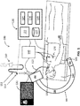
FIG. 1 is a diagram of an example electromagnetic navigation (EMN) system in accordance with this disclosure; -
FIG. 2 is a flow diagram of a method of generating a simulated map in accordance with this disclosure; -
FIG. 3 is a flow diagram of a method of magnetic interference correction in accordance with this disclosure; and -
FIG. 4 is a block diagram of the computing device ofFIG. 1 in accordance with embodiments of the disclosure. - As described above, to accurately determine sensor location and/or orientation, a detailed map of electromagnetic (EM) field measurements at respective sensor locations is generated. Generating such a map, however, requires taking precise electromagnetic field measurements at, for example, hundreds of thousands or more locations within the expected electromagnetic volume.
- The burden of generating electromagnetic field maps increases in circumstances where there are many antennae in the antenna assembly. For example, in order to enable an electromagnetic sensor to reach deeper portions of the body of the patient, and/or remain within the body during subsequent medical procedures without interfering with additional medical devices, it may be desirable to employ a small electromagnetic sensor, such as a single-coil electromagnetic sensor. However, to employ a small electromagnetic sensor for EMN while maintaining the ability to determine multiple (for example, five or six) degrees of freedom of the sensor, multiple antennae may be required to increase the number of radiated electromagnetic fields to be sensed. In such a case, the above-noted exhaustive mapping procedure may need to be conducted for each antenna assembly design. Moreover, given potential variations from manufacturing, the mapping procedure may even need to be completed for each instance of a specific antenna assembly design (i.e., each individual antenna assembly manufactured).
- Making all of this more complex is the fact that many devices that may be found in a clinical space include metal components. These metal components when placed in proximity to an EM field can have Eddy currents induced in them, resulting in the generation of interfering EM fields. These interfering EM fields may be detected by the sensors and as a result the accuracy of the detected position and orientation of an EM sensor within the EM field suffers.
- This disclosure relates to systems and methods for correcting errors in determining the position and orientation of electromagnetic sensors caused by magnetic fields induced in nearby metallic equipment, which interfere with mapped EM fields during an EMN procedure. By correcting for these interference magnetic fields, the accuracy of the determined position and orientation is increased.
- In one application of the instant methods, an ultra-high density (UHD) EM field map is generated for a given EM field generator having multiple antennae. In general, for advanced EMN systems a UHD map is used to determine a location and/or an orientation of a sensor. The sensor typically includes multiple coils. The geometric configurations of the antennas that make up the EM field generator enable mathematical calculation of an expected or theoretical EM field strength at every UHD gridpoint within an EM volume. The EM sensor senses EM field strengths, and an
EMN system 100 identifies the location and the orientation of the EM sensor based on the sensed EM field strengths and the expected EM field strengths of the UHD map. - The magnetic field will typically manifest itself in an additive field (in addition to the expected field strengths and directions at a given point). This additive field may have different gains for each of the antennas that make up the EM field generator, but the vector of the additive field will all be in the same direction across all antennas. Thus, in accordance with the disclosure, predetermined polynomials are evaluated using the first magnetic field vector measurements to obtain first position and orientation information for the plurality of sensors. Then, starting with the first position information, a simulated map is searched for position information of the sensors such that the difference between (a) the sum of simulated magnetic field vectors corresponding to the position information and interference magnetic field vectors, which is rotated according to orientation information, and (b) the second magnetic field vector measurements are minimized. In this manner, the interference magnetic field may be determined and corrected position information regarding the sensors may be obtained.
-
FIG. 1 illustrates an example electromagnetic navigation (EMN)system 100, which is configured to identify a location and/or an orientation of a medical device, or sensor thereof, navigating (e.g., to a target) within the patient's body by using an antenna assembly, which includes a plurality of antennas and generates EM fields. TheEMN system 100 is further configured to augment computed tomography (CT) images, magnetic resonance imaging (MRI) images, or fluoroscopic images in navigation through patient's body toward a target of interest, such as a diseased portion in a luminal network of a patient's lung. - The
EMN system 100 includes aplatform 140 that is configured to provide a flat surface upon which thepatient 150 lies during the EMN navigation procedure. Theantenna assembly 145, which may also be referred to as an EM field generating device, is arranged upon theplatform 140 or is included as a component of theplatform 140. Theantenna assembly 145 includes multiple antennas, such as planar loop antennas (not shown inFIG. 1 ). In some embodiments, the antenna assembly includes, on a single substrate, multiple planar antennas having characteristics, such as geometries and/or relative locations that are diverse from one another, that enable multiple (for example, six) degrees of freedom of a small electromagnetic sensor, such as a single-coil sensor, to be determined. Example aspects of theantenna assembly 145 are described in further detail below. - With the
patient 150 lying upon theplatform 140, the one or more processors 124 (or another signal generator not shown inFIG. 1 ) generate and provide to the antennas of theantenna assembly 145 one or more EM signals that are radiated by the antennas in a manner sufficient to surround a portion of thepatient 150. In some aspects, theantenna assembly 145 includes a connector that has at least two terminals, and the trace of the antenna (not shown inFIG. 1 ) has two ends that are coupled to the two connector terminals, respectively, to form a signal communication path from the one ormore processors 145 to the antenna. - The
EMN system 100 also includes acatheter guide assembly 110, abronchoscope 115, acomputing device 120, amonitoring device 130, anEM field generator 140, atracking device 160, andreference sensors 170. Thebronchoscope 115 is operatively coupled to thecomputing device 120 and themonitoring device 130 via a wired connection (as shown inFIG. 1 ) or wireless connection (not shown inFIG. 1 ). Thereference sensors 170 may include three patient sensors placed on the patient. One patient sensor may be placed on the sternum of the patient and the other two patient sensors may be placed on the ribs of the patient. - The
bronchoscope 115 is inserted into the mouth of apatient 150 and captures images of the luminal network of the lung. In theEMN system 100, inserted into thebronchoscope 115 is acatheter guide assembly 110 for achieving access to the periphery of the luminal network of the lung of thepatient 150. Thecatheter guide assembly 110 may include an extended working channel (EWC) 111 with anEM sensor 112 at the distal portion of theEWC 111. A locatable guide catheter (LG) may be inserted into theEWC 111 with another EM sensor at the distal portion of the LG. TheEM sensor 112 at the distal portion of theEWC 111 or the LG is used to identify a location and/or an orientation of theEWC 111 or the LG while navigating through the luminal network of the lung. Due to the size restriction in theEWC 111 or the LG, in some embodiments, theEM sensor 112 may include only one single coil for detecting EM field strength of an EM field over thepatient 150. However, the number of coils in the EM sensor is not limited to one but may be two or more. - The
computing device 120, such as, a laptop, desktop, tablet, or other similar computing device, includes adisplay 122, one ormore processors 124,memory 126, an AC current driver 127 for providing AC current signals to theantenna assembly 145, anetwork card 128, and aninput device 129. The particular configuration of thecomputing device 120 illustrated inFIG. 1 is provided as an example, but other configurations of the components shown inFIG. 1 as being included in thecomputing device 120 are also contemplated. In particular, in some embodiments, one or more of the components (122, 124, 126, 127, 128, and/or 129) shown inFIG. 1 as being included in thecomputing device 120 may instead be separate from thecomputing device 120 and may be coupled to thecomputing device 120 and/or to any other component(s) of thesystem 100 by way of one or more respective wired or wireless path(s) to facilitate the transmission of power and/or data signals throughout thesystem 100. For example, although not shown inFIG. 1 , the AC current driver 127 may, in some example aspects, be separate from thecomputing device 120 and may be coupled to theantenna assembly 145 and/or coupled to one or more components of thecomputing device 120, such as theprocessor 124 and thememory 126, by way of one or more corresponding paths. - In some aspects, the
EMN system 100 may also include multiple computing devices, wherein the multiple computing devices are employed for planning, treatment, visualization, or helping clinicians in a manner suitable for medical operations. Thedisplay 122 may be touch-sensitive and/or voice-activated, enabling thedisplay 122 to serve as both input and output devices. Thedisplay 122 may display two-dimensional (2D) images or three-dimensional (3D) model of a lung to locate and identify a portion of the lung that displays symptoms of lung diseases. - The one or
more processors 124 execute computer-executable instructions. Theprocessors 124 may perform image-processing functions so that the 3D model of the lung can be displayed on thedisplay 122 or location algorithm to identify a location and an orientation of theEM sensor 112. In embodiments, thecomputing device 120 may further include a separate graphic accelerator (not shown) that performs only the image-processing functions so that the one ormore processors 124 may be available for other programs. Thememory 126 stores data and programs. For example, data may be mapping data for the EMN or any other related data such as a UHD map, image data, patients' medical records, prescriptions and/or history of the patient's diseases. - The ultra-high density (UHD) map may include multiple gridpoints in a fine coordinate system of the EM volume in which a medical device (e.g., the
EWC 111, LG, treatment probe, or other surgical devices) is to be navigated, and expected EM field strengths at each of the plurality of gridpoints. As theEM sensor 112 senses an EM field strength at a given point, the one ormore processors 124 identifies the location of theEM sensor 112 within the EM volume based on the sensed EM field strength and the expected EM field strengths in the UHD map. Further, an orientation of the medical device may be also calculated based on the sensed EM field strength and the UHD map. - As shown in
FIG. 1 , theEM field generator 140 is configured to provide a flat surface for thepatient 150 to lie upon and includes anantenna assembly 145. When thepatient 150 lies upon on theEM field generator 140, theantenna assembly 145 generates an EM field sufficient to surround a portion of thepatient 150 or the EM volume. Theantenna assembly 145 includes a plurality of antennas, each of which may include a plurality of loops. Each antenna is configured to generate an EM waveform having a corresponding frequency. The number of antennas may be at least six and in at least one embodiment is nine so that nine different EM waveforms are generated. - A time multiplexing method may be employed in generating the EM waveforms. For example, the antennas of the
antenna assembly 145 may generate EM waveforms with the same frequency at different times during a period. Alternatively, frequency multiplexing method may be employed, where each antenna generates EM waveform having a frequency different from each other. In still another configuration, a combination of the time multiplexing and frequency multiplexing methods may be employed. The antennas are grouped into more than one group. Antennas in the same group generate EM waveforms having the same frequency but at different times. Antennas in different groups may generate EM waveforms having different frequencies from each other. Corresponding de-multiplexing method is to be used to separate EM waveforms. - Each antenna may have a geometric configuration (for instance, where the antennae each have geometric configurations based on linear portions of printed circuit board (PCB) traces or wires, which facilitate use of the superposition principle in computing the total contribution of the fields generated by way of each antenna to the total combined EM field within the volume) so that each portion of the plurality of loops can be expressed as mathematical relationships or equations. The magnetic field can thus be computed for each trace on the antenna and the contributions from all traces can be summed. Based on this geometric configuration, expected EM field strength at each gridpoint in the UHD map can be theoretically or mathematically calculated via a simulation.
- In general, the
computing device 120 of theEMN system 100 controls theantenna assembly 145 embedded in theEM field generator 140 to generate an EM field, receives sensed results from theEM sensor 112, and determines a location and an orientation of theEM sensor 112 in the EM volume. - The
computing device 120 includes a clock, which generates a clock signal used for generating the EM field and sampling the sensed results. Since the same clock signal is used for generating the EM field and sampling the sensed EM field, synchronization between the magnetic field generation circuitry (e.g., a waveform generator) and the waveform acquisition circuitry (e.g., a digitizer) may be achieved. In other words, when the clock provides a clock signal to the waveform generator and the digitizer, the EM waveforms generated by theantenna assembly 145 are digitally sampled by digitizer substantially at the same time. The digitizer may include an analog-to-digital converter (ADC, which is not shown) to digitally sample the sensed results and an amplifier (which is not shown) to amplify the magnitude of the sensed result so that the magnitude of the sensed results is within the operable range of the ADC. In an aspect, the digitizer may include a pre-amplifier and post-amplifier so that the magnitude of the sensed result is amplified to be within the operable range of the ADC by the pre-amplifier and digital samples are also amplified to the magnitude of the sensed result by the post-amplifier. - A demodulator demodulates the digital samples to remove unwanted signals (e.g., noises) and to restore the EM waveforms, which have been generated by the
antenna assembly 145. The demodulator may use time de-multiplexing method, frequency de-multiplexing method, or combination of both to separate and identify the EM waveforms depending on the method used by the antennas of theantenna assembly 145 to generate the EM waveforms, and to determine EM field strength affected by each of the antenna of theantenna assembly 145. - For example, when the
antenna assembly 145 includes six antennas, the demodulator is capable of identifying six EM field strengths, which is sensed by theEM sensor 112, for the six antennas, respectively. In a case when the number of antennas is nine, the outputs of the demodulator may be expressed in a form of a nine by one matrix. Based on the modulation method (e.g., time multiplexing, frequency multiplexing, or a combination thereof) utilized by the antennas, the demodulator demodulates the sensed result. - For example, when the antennas of the
antenna assembly 145 utilize frequency multiplexing, the demodulator may use a set of finely tuned digital filters. Orthogonal frequency division multiplexing may also be utilized, in which the EM field and sampling frequencies are chosen in such a way that only the desired frequency from a specific antenna is allowed to pass while other frequencies are precisely stopped. In an aspect, the demodulator may use a multiple tap orthogonal frequency matched filter, in which the digital filter for a specific frequency is tuned to the desired demodulation window. - The
memory 126 may store data and programs related to identification of a location and an orientation. The data includes an ultra-high density (UHD) map, which includes a plurality of gridpoints for the EM volume and expected EM field strengths at the gridpoints. The UHD map may be based on three-axis coordinate system, where each gridpoint has three coordinates corresponding to the three axes, respectively. In this case, the expected EM field strength at each gridpoint may include one EM field strength value along each axis for each EM waveform. For example, if there are nine antennas generating nine different EM waveforms, each of which having a separate frequency, and three axes are x, y, and z axes, the expected EM field strength may include nine EM field strength values along the x axis, nine EM field strength values along the y axis, and nine EM field strength values along the z axis, at each gridpoint. Such expected EM field strength at each gridpoint may be expressed in a nine by three matrix form. - The UHD map may be made with computations in a simulation, which includes theoretically calculated EM field strengths at each axis at each gridpoint in the fine coordinate system, and measurement, which includes measurements at each axis at each gridpoint in the coarse coordinate system. The fine coordinate system includes all the gridpoints in the coarse coordinate system and the gridpoints of the fine coordinate system are more finely distributed than those of the coarse coordinate system. By using the geometric configuration of the antennas of the
antenna assembly 145, measurement may not have to be made with the fine coordinate system. Rather, the measurement may be made in the coarse coordinate system and theoretical computations may be made in the fine coordinate system. By combining the measurements in the coarse coordinate system with the theoretical computations in the fine coordinate system, the UHD map may be generated. Generation of the UHD map based on the measurement and calculations will be described in further detail with respect toFIG. 2 below. - After passage of time or due to foreign objects near the
EMN system 100, measurements by theEM sensor 112 or other hardware may need to be calibrated. Such calibration data may be also stored in thememory 126 in a form of sensor calibration and hardware calibration. - When the
computing device 120 receives measurement data from theEM sensor 112 via the demodulator, thecomputing device 120 uses the location algorithm, which is also stored in thememory 126, with the UHD map to identify the location and the orientation of theEM sensor 112. - The location algorithm may utilize any error minimization algorithm in identifying the location and the orientation of the
EM sensor 112. For example, Levenberg-Marquardt algorithm may be employed to minimize errors between (a) the expected magnetic field strengths of the UHD map in combination with magnetic interference field strengths, and (b) the sensed results. Other error minimization methods or algorithms, which a person having ordinary skill in the art can readily appreciate, may also be utilized without departing from the scope of this disclosure. - The
memory 126 further includes applications, which can be utilized by thecomputing device 120 of theEMN system 100 and which uses information regarding the location and the orientation of theEM sensor 112. Such application may be a displaying application, which displays a graphical representation of a medical device, on which theEM sensor 112 is mounted or installed, at the location of theEM sensor 112 and along the orientation of theEM sensor 112 in the EM volume, an application for treatment, which determines whether a medical device is near a target of interest, or any other applications, which use the location and the orientation of theEM sensor 112. - The
EM field generator 140 produces EM fields around the patient. These EM fields will induce currents in any metal object that might come in proximity to the EM field, such as afluoroscope 180. Thefluoroscope 180 illustrated inFIG. 1 is a C-mount fluoroscope which includes anx-ray source 186 and animage acquisition module 182 at opposite ends of a C-mount 184. Theimage acquisition module 182 may include an image intensifier (not shown), a front face (not shown) which faces thex-ray source 186, and a CCD camera (not shown), mounted on the end of the image intensifier that is opposite front face, for acquiring images that are intensified by the image intensifier. The image intensifier may be housed in a cylindrical housing. In addition, theimage acquisition module 182 may include an annular compensator (not shown). The EM fields generated by the EM field generator may induce Eddy currents in the various components of the fluoroscope. For example, Eddy currents may be induced in the image intensifier of theimage acquisition module 182. - In practice, the
fluoroscope 180 is mobile and may be placed in different locations within a procedure room, but, as described above, includes a number of large metal components. Thus, when a fluoroscope is brought into the EM field, such as when navigation to a desired target is near its end and real-time imaging is desired, the act of moving the fluoroscope can degrade the accuracy of the detected location of theEM sensor 112 within the EM field. - Though the
EM sensor 112 has been referred to,reference sensors 170 placed on the exterior of the patient and referred to collectively as the patient sensor triplet (PST) are of similar construction and provide the primary source of data tocomputing device 120 for dynamic interference correction. - Because there are, in one example, nine antennae that make up the EM field generator, and each is generating its own EM field, each of these fields will induce a separate current in a metal object such as the fluoroscope. Each of these currents will produce an interfering EM field. These fields will be identifiable at every position in the sensing volume produced by the
EM field generator 140 as an additive field. This additive field will appear in all nine frequencies of the measured magnetic fields used to determine the location of thereference sensors 170 in the map. - In the case where the navigation system is used with a Fluoroscope, the magnetic interference generated by the Fluoroscope primarily impacts the patient sensors because the Fluoroscope is closest source of potential magnetic interference to the patient sensors. The patient sensors form the body coordinate system. When the positions of the patient sensors are inaccurate, the positions of the catheter sensor and the EWC sensor in the body coordinates are inaccurate even though their position in antenna coordinates are accurate. Thus, the computing device solves for interference for each of the three patient sensors. Optionally, the computing device solves for interference for a catheter sensor connected to the navigation system. In general, when solving for the magnetic interference on the patient sensors, the position of the EWC sensor on the CT image is more accurate. Thus, the computing device does not solve for interference on the EWC sensor.
- To solve for the magnetic interference on the
patient sensors 170, each of which may have three channels corresponding to three sensor coils disposed orthogonal to each other, and optionally the catheter sensor, starting positions and orientations of thepatient sensors 170 are computed using 3 antenna (disregarding the other 6 antennas) and using polynomials found in a mapping process. Next, a Levenberg-Marquadt search is performed to try to find on a ultra-high definition (UHD) map the 3 (or 4) sensor positions such that the sum of the magnetic field vectors from the map (interpolated to the sensor positions) and the solved magnetic interference vectors, which is rotated according to the solved sensors orientations (to get the sum in the sensors' coordinate systems) would be the closest to the actual sensor measurements or pickups. - The Levenberg-Marquadt search assumes that the Eddy currents induced in the source of dynamic interference, e.g., a Fluoroscope, are flowing in the same route or path for all magnetic fields generating the Eddy currents. The route or path may be a loop in any given shape, such as a circle or ring, a square, a rectangle, or a star. For example, in the case of
fluoroscope 180, the induced currents may flow in a metal ring of the fluoroscope image intensifier. Even though the magnetic fields are in different orientations, the Eddy currents are induced in the same route. Thus, the induced Eddy currents generate nine magnetic interference vectors that, for a particular sensor position, all share the same direction. The amplitude ratios are determined according to the induced Eddy currents. For a second sensor, all amplitude ratios are the same as for a first sensor, and all magnetic interference vectors are in the same direction, but are in a different direction than the direction of all the magnetic interference vectors at the first sensor. - Accordingly, when the computing device solves for the magnetic interference on the 3 or 4 sensors, the computing device solves for eight global ratios. This assumes that the amplitude of a first magnetic interference vector at a first frequency is 1 and that the eight global ratios are the amplitudes of the other magnetic interference vectors at eight other frequencies relative to the amplitude of the first magnetic interference vector at the first frequency. Thus, for each sensor, the computing device solves for its position and orientation and the interference vectors (each of which comprises three coordinates) of the first frequency and the other eight frequencies. The other eight interference vectors are computed by multiplying the interference vector of the first frequency by the eight global ratios. In summary, for an example navigation system including three patient sensors and nine antennae, the computing device solves for 35 variables (that is, (6 degrees of freedom of the source of dynamic interference + 3 coordinates of an interference vector) ∗ 3 patient sensors + 8 common or global ratios) based on 81 sensor data points (that is, 3 sensed coordinates ∗ 9 magnetic fields ∗ 3 patient sensors).
- A high definition (HD) map provides a low-resolution grid of positions (e.g., every 5 mm). Each grid position includes as many magnetic vectors as there are antennas in the
antenna assembly 145. For example, if there are nine antennae, there will be 9 magnetic field vectors at each grid position. In accordance with this disclosure, a method for defining an ultra-HD (UHD) map, which provides a high-resolution grid of positions (e.g., every 1 mm), for a given system is described. The starting point for the UHD map is a calculated or simulated UHD map that can be derived from the construction or geometry of theantenna assembly 145 and the driving frequencies of the individual antenna using the Biot-Savart law for mapping magnetic fields. - In the process of installing an individual EM board 140 (including antenna assembly 145) as part of the
EMN system 100 in a specific location, a mapping of the EM field generated by theEM board 140 is undertaken. This in-situ mapping is necessary to account for eddy currents that can be induced in the metal frames of surgical beds and other stationary metal components that are within the magnetic field. These eddy currents in the metal components, particularly the surgical bed, generate their own magnetic fields, referred to as additive magnetic fields. These additive magnetic fields are at the same frequencies as the magnetic fields generated by theantenna assembly 145. -
FIG. 2 illustrates anexample method 200 of generating a high-resolution map for use by magnetic interference correction methods of this disclosure. In accordance with the generation of the UHD map, actual readings of the EM fields generated by the nine antennae are taken using an EM field sensor atblock 202 and associated with positions in a low-resolution grid of positions. In one example, the low-resolution grid is a 9×9×9 matrix of positions. The EM field measurements at each of these positions is compared by theprocessor 124 to that of the simulated UHD map atblock 204. The difference between the detected magnetic fields of the low-resolution gird and the magnetic fields of the simulated UHD map at each of the positions of the low-resolution grid, represents the interference (e.g., bed interference) that is generated by the eddy currents (the additive magnetic fields) and is calculated atblock 206. - The low-resolution grid (i.e., the sampling points) is spaced over the entirety of the
EM board 140. Because the interference or additive magnetic fields do not dramatically change between the sample points, theprocessor 124 is able to interpolate, atblock 208, the low-resolution bed interference map into a high-resolution grid having the same number of positions as the calculated UHD map to generate a high definition map of the interference. The UHD map of the interference is then added to the simulated UHD map to provide an adjusted UHD map atblock 210. This adjusted UHD map is saved in memory atblock 212 and is then used for future navigation using theEMN system 100. - Each of the multiple antennas may be configured to radiate a separate EM field, for example, using frequency division multiplexing and/or time division multiplexing controlled by the
processors 124 or by another generator. For example, the antennas, in some aspects, may be configured to radiate multiple EM fields sufficient in number and/or sufficient in diversity of characteristics (such as frequency, time, modulation scheme, and/or the like) to enable a single-coil electromagnetic sensor mounted on theEWC 111, or on any other medical device, to be used to determine the location and/or the orientation of the sensor, theEWC 111, and/or the medical device. Theantenna assembly 145 may, for instance, include six to nine or more loop antennas. In some embodiments, for each of the loop antennas, the distances between its adjacent loops increase as the loops become larger. For example, for each of the planar antennas, respective distances between adjacent pairs of loops may increase in a direction from an innermost one of the loops to an outermost one of the loops of the respective planar antenna. - Each of the antennas of the designed antenna assembly can be printed, deposited, or fabricated on a respective substrate layer and can be used as the
EM field generator 145 of theEMN system 100 ofFIG. 1 . Further, by virtue of employing straight linear portions to constitute the loop antennas, electromagnetic fields generated by each linear portion can be theoretically and accurately calculated using the Biot-Savart-Laplace law at any point in the EM volume. -
FIG. 3 is a flow diagram of a method of magnetic interference correction in accordance with an embodiment of this disclosure. Atblock 302, a computing device obtains, from three patient sensors, first measurements of magnetic fields generated by a portion of a plurality of antennae of an antenna assembly (e.g., three antenna our of nine antennae of an antenna assembly) disposed under the patient. At block 304, the computing device evaluates predetermined polynomials using the first measurements to obtain position and orientation information for a plurality of sensors, such as three patient sensors. The predetermined polynomials provide a relationship between magnetic field vector measurements obtained by the three patient sensors and position and orientation information of the three patient sensors. The predetermined polynomials are determined based on calibration measurements of the magnetic fields generated by the three antennae at known positions and orientations of the patient sensors. - At
block 306, the computing device obtains, from a plurality of sensors, such as three patient sensors, second measurements of magnetic fields generated by a plurality of antennae, such as nine antennae, of the antenna assembly. Atblock 308, the computing device adds a simulated magnetic field corresponding to position information in a simulated map to an interference magnetic field and rotates the result according to the orientation information. Atblock 310, the computing device determines the difference between the rotated sum of magnetic fields and the second measurements of the magnetic fields generated by the nine antennae. Atblock 312, the computing device determines whether there is convergence on a minimum difference. If there is no convergence, the computing device selects another nearby position in the simulated map atblock 312 and repeats blocks 308-312. In some embodiments, blocks 308-314 may be performed according to a Levenberg-Marquadt search algorithm. In other embodiments, blocks 308-314 may be performed according to another search algorithm that seeks to minimize the difference between the rotated sum of magnetic fields and the second measurements. - If there is convergence on a minimum difference between the rotated sum of magnetic fields and the second measurements, the computing device uses the position and orientation information of the patient sensor corresponding to the minimum difference between the rotated sum of magnetic fields and the second measurements at
block 316. Atblock 318, the computing device determines whether there is another patient sensor whose magnetic field measurements need to be processed in order to determine the corrected position and orientation information of the other patient sensor. If there is another patient sensor whose magnetic field measurements need to be processed, the computing device returns to block 306 to obtain, from the other patient sensor, second measurements of the magnetic fields generated by the nine antenna of the antenna assembly. If there is not another patient sensor whose magnetic field measurements need to be processed, the computing device returns to block 302 to repeat themethod 300, as the patient sensors and/or the fluoroscope (or other equipment near the patient sensors) may have moved to different positions and/or orientations. - Turning now to
FIG. 4 , there is shown a block diagram of acomputing device 400, which can be used as theEMN system 100, the control workstation 102, thetracking device 160, and/or a computer performing themethods FIGS. 2 and3 . Thecomputing device 400 may include one or more of each of the following components: amemory 402, aprocessor 404, adisplay 406,network interface controller 408, aninput device 410, and/or an output module 412. - The
memory 402 includes any non-transitory computer-readable storage media for storing data and/or software that is executable by theprocessor 404 and which controls the operation of thecomputing device 400. In an embodiment, thememory 402 may include one or more solid-state storage devices such as flash memory chips. Alternatively, or in addition to the one or more solid-state storage devices, thememory 402 may include one or more mass storage devices connected to theprocessor 404 through a mass storage controller (not shown inFIG. 4 ) and a communications bus (not shown inFIG. 4 ). Although the description of computer-readable media contained herein refers to a solid-state storage, it should be appreciated by those skilled in the art that computer-readable storage media can be any available media that can be accessed by theprocessor 404. That is, computer readable storage media include non-transitory, volatile and non-volatile, removable and non-removable media implemented in any method or technology for storage of information such as computer-readable instructions, data structures, program modules or other data. For example, computer-readable storage media include RAM, ROM, EPROM, EEPROM, flash memory or other solid state memory technology, CD-ROM, DVD, Blu-Ray or other optical storage, magnetic cassettes, magnetic tape, magnetic disk storage or other magnetic storage devices, or any other medium which can be used to store the desired information and which can be accessed by thecomputing device 400. - The
memory 402 may storeapplication 416 and/orCT data 414. Theapplication 416 may, when executed by theprocessor 404, cause thedisplay 406 to presentuser interface 418 on thedisplay 406. - The
processor 404 may be a general purpose processor, a specialized graphic processing unit (GPU) configured to perform specific graphics processing tasks while freeing up the general purpose processor to perform other tasks, a programmable logic device such as a field programmable gate array (FPGA) or complex programmable logic device (CPLD), and/or any number or combination of such processors or devices configured to work independently or cooperatively. - The
display 406 may be touch-sensitive and/or voice-activated, enabling thedisplay 406 to serve as both an input and output device. Alternatively, a keyboard (not shown), mouse (not shown), or other data input devices may be employed. - The
network interface 408 may be configured to connect to a network, such as a local area network (LAN) including a wired network and/or a wireless network, a wide area network (WAN), a wireless mobile network, a Bluetooth network, and/or the Internet. For example, thecomputing device 400 may receive the predetermined functions or polynomials and perform themethod 300 ofFIG. 3 to search for a position and orientation of a patient or catheter sensor. Thecomputing device 400 may receive updates to its software, for example,application 416, via thenetwork interface controller 408. Thecomputing device 400 may also display notifications on thedisplay 406 that a software update is available. - In another aspect, the
computing device 400 may receive computed tomographic (CT) image data of a patient from a server, for example, a hospital server, Internet server, or other similar servers, for use during surgical planning. Patient CT image data may also be provided to thecomputing device 400 via a removable memory (not shown inFIG. 4 ). -
Input device 410 may be any device by means of which a user may interact with thecomputing device 400, such as, for example, a mouse, keyboard, foot pedal, touch screen, and/or voice interface. - Output module 412 may include any connectivity port or bus, such as, for example, parallel ports, serial ports, universal serial busses (USB), or any other similar connectivity port known to those skilled in the art.
- The
application 416 may be one or more software programs stored in thememory 402 and executed by theprocessor 404 of thecomputing device 400. During a calibration phase, one or more software programs in theapplication 416 may be loaded from thememory 402 and executed by theprocessor 404 to determine functions or polynomials that provide a relationship between (a) magnetic field vector measurements obtained by the patient sensors and (b) position and orientation information of the patient sensors based on calibration measurements of the magnetic fields generated by a portion of the antennae at known positions and orientations of the patient sensors. In some embodiments, during a planning phase, one or more programs in theapplication 416 guides a clinician through a series of steps to identify a target, size the target, size a treatment zone, and/or determine an access route to the target for later use during the navigation or procedure phase. In some other embodiments, one or more software programs in theapplication 416 may be loaded on computing devices in an operating room or other facility where surgical procedures are performed, and is used as a plan or map to guide a clinician performing a surgical procedure, but without any feedback from the medical device used in the procedure to indicate where the medical device is located in relation to the plan. - The
application 416 may be installed directly on thecomputing device 400, or may be installed on another computer, for example a central server, and opened on thecomputing device 400 via thenetwork interface 408.Application 416 may run natively on thecomputing device 400, as a web-based application, or any other format known to those skilled in the art. In some embodiments, theapplication 416 will be a single software program having all of the features and functionality described in this disclosure. In other embodiments, theapplication 416 may be two or more distinct software programs providing various parts of these features and functionality. For example, theapplication 416 may include one software program for determining the functions or polynomials in a calibration phase, another one for taking magnetic field measurements from the patient sensors and/or catheter sensor, and a third program for performing a search on the UHD map. In such instances, the various software programs forming part of theapplication 416 may be enabled to communicate with each other and/or import and export various data including settings and parameters relating to the patient sensors. For example, the predetermined functions or polynomials generated by one software program may be stored and exported to be used by a second software program that evaluates the predetermined functions or polynomials to obtain initial position and orientation information, and the initial position and orientation information may be also stored and exported to be used by a searching software program to search a UHD map starting with the initial position and orientation information. - The
application 416 may communicate with auser interface 418 which generates a user interface for presenting visual interactive features to a user, for example, on thedisplay 406 and for receiving input, for example, via a user input device. For example,user interface 418 may generate a graphical user interface (GUI) and output the GUI to thedisplay 406 for viewing by a user. - In a case that the
computing device 400 may be used as theEMN system 100, the control workstation 102, or thetracking device 160, thecomputing device 400 may be linked to themonitoring device 130, thus enabling thecomputing device 400 to control the output on themonitoring device 130 along with the output on thedisplay 406. Thecomputing device 400 may control themonitoring device 130 to display output which is the same as or similar to the output displayed on thedisplay 406. For example, the output on thedisplay 406 may be mirrored on themonitoring device 130. Alternatively, thecomputing device 400 may control themonitoring device 130 to display different output from that displayed on thedisplay 406. For example, themonitoring device 130 may be controlled to display guidance images and information during the surgical procedure, while thedisplay 406 is controlled to display other output, such as configuration or status information of an electrosurgical generator (not shown inFIG. 1 ). - The
application 416 may include one software program for use during the planning phase, and a second software program for use during the navigation or procedural phase. In such instances, the various software programs forming part ofapplication 416 may be enabled to communicate with each other and/or import and export various settings and parameters relating to the navigation and treatment and/or the patient to share information. For example, a treatment plan and any of its components generated by one software program during the planning phase may be stored and exported to be used by a second software program during the procedure phase. - Although embodiments have been described in detail with reference to the accompanying drawings for the purpose of illustration and description, it is to be understood that the inventive processes and apparatus are not to be construed as limited. It will be apparent to those of ordinary skill in the art that various modifications to the foregoing embodiments may be made without departing from the scope of this disclosure. For example, various steps of the methods described herein may be implemented concurrently and/or in an order different from the example order(s) described herein.
- The invention may be described by reference to the following numbered paragraphs:-
- 1. A navigation system for magnetic interference correction, comprising:
- a plurality of antennae configured to generate a plurality of magnetic fields at different frequencies;
- a plurality of sensors configured to measure the plurality of magnetic fields;
- a computing device configured to:
- obtain first magnetic field vector measurements from the plurality of sensors for a portion of the plurality of antennae;
- evaluate predetermined functions using the first magnetic field vector measurements to obtain first position and orientation information for the plurality of sensors;
- obtain second magnetic field vector measurements from the plurality of sensors for the plurality of antennae; and
- search, starting with the first position information, a simulated map for position information of the plurality of sensors such that the difference between (a) the sum of simulated magnetic field vectors corresponding to the position information and interference magnetic field vectors, which is rotated according to orientation information, and (b) the second magnetic field vector measurements are minimized.
- 2. The navigation system of paragraph 1, wherein the plurality of sensors includes three patient sensors.
- 3. The navigation system of paragraph 2, wherein the plurality of sensors further includes a catheter sensor.
- 4. The navigation system of paragraph 1, wherein determining the plurality of interference magnetic field vectors includes determining three coordinates of an interference magnetic field vector for each of the plurality of sensors at one frequency of a magnetic field generated by one antenna of the plurality of antennae and determining a plurality of ratios for a respective plurality of other frequencies of magnetic fields generated by other antennae of the plurality of antennae.
- 5. The navigation system of paragraph 1, wherein the plurality of antennae includes nine antennae.
- 6. The navigation system of paragraph 1, wherein the portion of the plurality of antennae includes three antennae.
- 7. The navigation system of paragraph 1, wherein searching the simulated map includes performing a Levenberg-Marquadt search.
- 8. The navigation system of paragraph 1, further comprising a medical device, which generates a plurality of interference magnetic fields from Eddy currents induced in the medical device by a respective plurality of magnetic fields generated by the respective plurality of antennae.
- 9. The navigation system of paragraph 8, wherein the medical device is a Fluoroscope or a robotic arm.
- 10. The navigation system of paragraph 1, wherein the computing device is further configured to determine functions that provide a relationship between (a) magnetic field vector measurements obtained by the plurality of patient sensors and (b) position and orientation information of the plurality of patient sensors based on calibration measurements of the magnetic fields generated by a portion of the plurality of antennae at known positions and orientations of the plurality of patient sensors.
- 11. A method for magnetic interference correction, comprising:
- obtaining, from a plurality of sensors, measurements of first magnetic fields generated by a portion of a plurality of antennae;
- evaluating predetermined functions using the first magnetic field measurements to obtain first position and orientation information for the plurality of sensors;
- obtaining second magnetic field measurements from the plurality of sensors for the plurality of antennae; and
- searching, starting with the first position information, a simulated map for position information of the plurality of sensors such that the difference between (a) the sum of simulated magnetic field corresponding to the position information and the interference magnetic field, which is rotated according to orientation information, and (b) the second magnetic field measurements is minimized.
- 12. The method of paragraph 11, wherein the plurality of sensors include three patient sensors.
- 13. The method of paragraph 11, wherein determining the plurality of interference vectors includes determining three coordinates of an interference vector for each of the plurality of patient sensors at one frequency of a magnetic field generated by one antenna of the plurality of antennae and determining a plurality of ratios for a respective plurality of other frequencies of magnetic fields generated by other antennae of the plurality of antennae.
- 14. The method of paragraph 11, wherein the plurality of antennae includes nine antennae.
- 15. The method of paragraph 11, wherein the portion of the plurality of antennae includes three antennae.
- 16. The method of paragraph 11, wherein searching the simulated map includes performing a Levenberg-Marquadt search.
- 17. The method of paragraph 11, further comprising determining functions that provide a relationship between (a) magnetic field vector measurements obtained by the plurality of patient sensors and (b) position and orientation information of the plurality of patient sensors based on calibration measurements of the magnetic fields generated by a portion of the plurality of antennae at known positions and orientations of the plurality of patient sensors.
Claims (15)
- A navigation system for magnetic interference correction, comprising:a plurality of antennae configured to generate a plurality of magnetic fields at different frequencies;a plurality of sensors configured to measure the plurality of magnetic fields;a computing device configured to:obtain first magnetic field vector measurements from the plurality of sensors for a portion of the plurality of antennae;evaluate predetermined functions using the first magnetic field vector measurements to obtain first position and orientation information for the plurality of sensors;obtain second magnetic field vector measurements from the plurality of sensors for the plurality of antennae; andsearch, starting with the first position information, a simulated map for position information of the plurality of sensors such that the difference between (a) the sum of simulated magnetic field vectors corresponding to the position information and interference magnetic field vectors, which is rotated according to orientation information, and (b) the second magnetic field vector measurements are minimized.
- The navigation system of claim 1, wherein the plurality of sensors includes three patient sensors.
- The navigation system of claim 2, wherein the plurality of sensors further includes a catheter sensor.
- The navigation system of any preceding claim, wherein determining the plurality of interference magnetic field vectors includes determining three coordinates of an interference magnetic field vector for each of the plurality of sensors at one frequency of a magnetic field generated by one antenna of the plurality of antennae and determining a plurality of ratios for a respective plurality of other frequencies of magnetic fields generated by other antennae of the plurality of antennae.
- The navigation system of any preceding claim, wherein the plurality of antennae includes nine antennae.
- The navigation system of any preceding claim, wherein the portion of the plurality of antennae includes three antennae.
- The navigation system of any preceding claim, wherein searching the simulated map includes performing a Levenberg-Marquadt search.
- The navigation system of any preceding claim, further comprising a medical device, which generates a plurality of interference magnetic fields from Eddy currents induced in the medical device by a respective plurality of magnetic fields generated by the respective plurality of antennae; preferably wherein the medical device is a Fluoroscope or a robotic arm.
- The navigation system of any preceding claim, wherein the computing device is further configured to determine functions that provide a relationship between (a) magnetic field vector measurements obtained by the plurality of patient sensors and (b) position and orientation information of the plurality of patient sensors based on calibration measurements of the magnetic fields generated by a portion of the plurality of antennae at known positions and orientations of the plurality of patient sensors.
- A method for magnetic interference correction, comprising:obtaining, from a plurality of sensors, measurements of first magnetic fields generated by a portion of a plurality of antennae;evaluating predetermined functions using the first magnetic field measurements to obtain first position and orientation information for the plurality of sensors;obtaining second magnetic field measurements from the plurality of sensors for the plurality of antennae; andsearching, starting with the first position information, a simulated map for position information of the plurality of sensors such that the difference between (a) the sum of simulated magnetic field corresponding to the position information and the interference magnetic field, which is rotated according to orientation information, and (b) the second magnetic field measurements is minimized.
- The method of claim 10, wherein the plurality of sensors include three patient sensors.
- The method of claim 10 or claim 11, wherein determining the plurality of interference vectors includes determining three coordinates of an interference vector for each of the plurality of patient sensors at one frequency of a magnetic field generated by one antenna of the plurality of antennae and determining a plurality of ratios for a respective plurality of other frequencies of magnetic fields generated by other antennae of the plurality of antennae.
- The method of any of claims 10 to 12, wherein the plurality of antennae includes nine antennae.
- The method of any of claims 10 to 12, wherein the portion of the plurality of antennae includes three antennae.
- The method of any of claims 10 to 14, wherein searching the simulated map includes performing a Levenberg-Marquadt search; and/or further comprising determining functions that provide a relationship between (a) magnetic field vector measurements obtained by the plurality of patient sensors and (b) position and orientation information of the plurality of patient sensors based on calibration measurements of the magnetic fields generated by a portion of the plurality of antennae at known positions and orientations of the plurality of patient sensors.
Applications Claiming Priority (3)
| Application Number | Priority Date | Filing Date | Title |
|---|---|---|---|
| US201862738148P | 2018-09-28 | 2018-09-28 | |
| US201962794209P | 2019-01-18 | 2019-01-18 | |
| US201962794435P | 2019-01-18 | 2019-01-18 |
Publications (1)
| Publication Number | Publication Date |
|---|---|
| EP3628222A1 true EP3628222A1 (en) | 2020-04-01 |
Family
ID=68165438
Family Applications (1)
| Application Number | Title | Priority Date | Filing Date |
|---|---|---|---|
| EP19200249.1A Withdrawn EP3628222A1 (en) | 2018-09-28 | 2019-09-27 | Systems and methods for magnetic interference correction |
Country Status (2)
| Country | Link |
|---|---|
| US (2) | US11944388B2 (en) |
| EP (1) | EP3628222A1 (en) |
Families Citing this family (3)
| Publication number | Priority date | Publication date | Assignee | Title |
|---|---|---|---|---|
| US9603668B2 (en) * | 2014-07-02 | 2017-03-28 | Covidien Lp | Dynamic 3D lung map view for tool navigation inside the lung |
| WO2025202910A1 (en) * | 2024-03-29 | 2025-10-02 | Auris Health, Inc. | Navigation updates for medical systems |
| CN120036937B (en) * | 2025-02-28 | 2026-01-06 | 北京长木谷医疗科技股份有限公司 | Intraoperative localization and navigation method for surgical robots based on anti-interference electromagnetic tracking |
Citations (4)
| Publication number | Priority date | Publication date | Assignee | Title |
|---|---|---|---|---|
| US20120165660A1 (en) * | 2005-05-05 | 2012-06-28 | Chunwu Wu | System and method for electromagnetic navigation in the vicnity of a metal object |
| EP2888997A1 (en) * | 2013-12-24 | 2015-07-01 | Biosense Webster (Israel), Ltd. | Adaptive fluoroscope location for the application of field compensation |
| US20150305823A1 (en) * | 2014-04-25 | 2015-10-29 | General Electric Company | System and method for processing navigational sensor data |
| US20180116722A1 (en) * | 2016-10-28 | 2018-05-03 | Covidien Lp | System and method for generating a map for electromagnetic navigation |
Family Cites Families (186)
| Publication number | Priority date | Publication date | Assignee | Title |
|---|---|---|---|---|
| US5767669A (en) * | 1996-06-14 | 1998-06-16 | Ascension Technology Corporation | Magnetic field position and orientation measurement system with dynamic eddy current rejection |
| SE9603314D0 (en) | 1996-09-12 | 1996-09-12 | Siemens Elema Ab | Method and apparatus for determining the location of a catheter within the body of a patient |
| US6016439A (en) | 1996-10-15 | 2000-01-18 | Biosense, Inc. | Method and apparatus for synthetic viewpoint imaging |
| US7027869B2 (en) | 1998-01-07 | 2006-04-11 | Asthmatx, Inc. | Method for treating an asthma attack |
| US9572519B2 (en) | 1999-05-18 | 2017-02-21 | Mediguide Ltd. | Method and apparatus for invasive device tracking using organ timing signal generated from MPS sensors |
| US6413981B1 (en) | 1999-08-12 | 2002-07-02 | Ortho-Mcneil Pharamceutical, Inc. | Bicyclic heterocyclic substituted phenyl oxazolidinone antibacterials, and related compositions and methods |
| US7366562B2 (en) | 2003-10-17 | 2008-04-29 | Medtronic Navigation, Inc. | Method and apparatus for surgical navigation |
| US8239001B2 (en) | 2003-10-17 | 2012-08-07 | Medtronic Navigation, Inc. | Method and apparatus for surgical navigation |
| US6493573B1 (en) | 1999-10-28 | 2002-12-10 | Winchester Development Associates | Method and system for navigating a catheter probe in the presence of field-influencing objects |
| US8644907B2 (en) | 1999-10-28 | 2014-02-04 | Medtronic Navigaton, Inc. | Method and apparatus for surgical navigation |
| WO2001031466A1 (en) | 1999-10-28 | 2001-05-03 | Winchester Development Associates | Coil structures and methods for generating magnetic fields |
| US6400139B1 (en) | 1999-11-01 | 2002-06-04 | Polhemus Inc. | Methods and apparatus for electromagnetic position and orientation tracking with distortion compensation |
| US6472372B1 (en) | 2000-12-06 | 2002-10-29 | Ortho-Mcneil Pharmaceuticals, Inc. | 6-O-Carbamoyl ketolide antibacterials |
| US20030013972A1 (en) | 2001-05-29 | 2003-01-16 | Makin Inder Raj. S. | Treatment of lung lesions using ultrasound |
| US7607440B2 (en) | 2001-06-07 | 2009-10-27 | Intuitive Surgical, Inc. | Methods and apparatus for surgical planning |
| US7998062B2 (en) | 2004-03-29 | 2011-08-16 | Superdimension, Ltd. | Endoscope structures and techniques for navigating to a target in branched structure |
| US7697972B2 (en) | 2002-11-19 | 2010-04-13 | Medtronic Navigation, Inc. | Navigation system for cardiac therapies |
| US7599730B2 (en) | 2002-11-19 | 2009-10-06 | Medtronic Navigation, Inc. | Navigation system for cardiac therapies |
| US7945309B2 (en) | 2002-11-22 | 2011-05-17 | Biosense, Inc. | Dynamic metal immunity |
| US7747307B2 (en) | 2003-03-04 | 2010-06-29 | Calypso Medical Technologies, Inc. | Method and system for marker localization |
| US7840253B2 (en) | 2003-10-17 | 2010-11-23 | Medtronic Navigation, Inc. | Method and apparatus for surgical navigation |
| US10195464B2 (en) | 2004-06-24 | 2019-02-05 | Varian Medical Systems, Inc. | Systems and methods for treating a lung of a patient using guided radiation therapy or surgery |
| US8611983B2 (en) | 2005-01-18 | 2013-12-17 | Philips Electronics Ltd | Method and apparatus for guiding an instrument to a target in the lung |
| US7335156B2 (en) | 2005-04-04 | 2008-02-26 | Ernest Paul Pattern | Digital electromagnetic pulse generator |
| US9204819B2 (en) | 2005-05-06 | 2015-12-08 | Vasonova, Inc. | Endovenous access and guidance system utilizing non-image based ultrasound |
| AU2006302057B2 (en) | 2005-10-11 | 2013-03-21 | Carnegie Mellon University | Sensor guided catheter navigation system |
| US8016749B2 (en) | 2006-03-21 | 2011-09-13 | Boston Scientific Scimed, Inc. | Vision catheter having electromechanical navigation |
| WO2007113719A1 (en) | 2006-03-31 | 2007-10-11 | Koninklijke Philips Electronics, N.V. | System for local error compensation in electromagnetic tracking systems |
| US9055906B2 (en) | 2006-06-14 | 2015-06-16 | Intuitive Surgical Operations, Inc. | In-vivo visualization systems |
| US8551109B2 (en) | 2006-06-28 | 2013-10-08 | Stereotaxis | Electrostriction devices and methods for assisted magnetic navigation |
| AU2007350982A1 (en) | 2006-11-10 | 2008-10-23 | Dorian Averbuch | Adaptive navigation technique for navigating a catheter through a body channel or cavity |
| WO2008111070A2 (en) | 2007-03-12 | 2008-09-18 | David Tolkowsky | Devices and methods for performing medical procedures in tree-like luminal structures |
| DE102007012361B4 (en) | 2007-03-14 | 2016-09-22 | Siemens Healthcare Gmbh | Method for determining the position of a medical instrument and position-determining device |
| WO2009074872A2 (en) | 2007-07-09 | 2009-06-18 | Superdimension, Ltd. | Patent breathing modeling |
| US8335359B2 (en) | 2007-07-20 | 2012-12-18 | General Electric Company | Systems, apparatus and processes for automated medical image segmentation |
| CN101808566B (en) | 2007-09-25 | 2012-02-29 | 奥林巴斯医疗株式会社 | Position detection device |
| JP5171373B2 (en) | 2008-04-24 | 2013-03-27 | ジーイー・メディカル・システムズ・グローバル・テクノロジー・カンパニー・エルエルシー | Magnetic resonance imaging apparatus and RF pulse applying method |
| US8218847B2 (en) | 2008-06-06 | 2012-07-10 | Superdimension, Ltd. | Hybrid registration method |
| US8382372B2 (en) | 2008-07-09 | 2013-02-26 | Siemens Aktiengesellschaft | Medical apparatus |
| US20100030061A1 (en) | 2008-07-31 | 2010-02-04 | Canfield Monte R | Navigation system for cardiac therapies using gating |
| US8175681B2 (en) | 2008-12-16 | 2012-05-08 | Medtronic Navigation Inc. | Combination of electromagnetic and electropotential localization |
| US20180009767A9 (en) | 2009-03-19 | 2018-01-11 | The Johns Hopkins University | Psma targeted fluorescent agents for image guided surgery |
| US10004387B2 (en) | 2009-03-26 | 2018-06-26 | Intuitive Surgical Operations, Inc. | Method and system for assisting an operator in endoscopic navigation |
| US8611984B2 (en) | 2009-04-08 | 2013-12-17 | Covidien Lp | Locatable catheter |
| US8494613B2 (en) | 2009-08-31 | 2013-07-23 | Medtronic, Inc. | Combination localization system |
| US8706184B2 (en) | 2009-10-07 | 2014-04-22 | Intuitive Surgical Operations, Inc. | Methods and apparatus for displaying enhanced imaging data on a clinical image |
| JP6153865B2 (en) | 2010-05-03 | 2017-06-28 | ニューウェーブ メディカル, インコーポレイテッドNeuwave Medical, Inc. | Energy delivery system |
| US10165928B2 (en) | 2010-08-20 | 2019-01-01 | Mark Hunter | Systems, instruments, and methods for four dimensional soft tissue navigation |
| US8971993B2 (en) | 2010-11-19 | 2015-03-03 | Mediguide Ltd. | Systems and methods for navigating a surgical device |
| EP2675351B1 (en) | 2011-02-17 | 2021-06-23 | Tyto Care Ltd. | System, handheld diagnostics device and methods for performing an automatic and remote trained personnel guided non-invasive medical examination |
| US10391277B2 (en) | 2011-02-18 | 2019-08-27 | Voxel Rad, Ltd. | Systems and methods for 3D stereoscopic angiovision, angionavigation and angiotherapeutics |
| US10362963B2 (en) | 2011-04-14 | 2019-07-30 | St. Jude Medical, Atrial Fibrillation Division, Inc. | Correction of shift and drift in impedance-based medical device navigation using magnetic field information |
| US8900131B2 (en) | 2011-05-13 | 2014-12-02 | Intuitive Surgical Operations, Inc. | Medical system providing dynamic registration of a model of an anatomical structure for image-guided surgery |
| US8827934B2 (en) | 2011-05-13 | 2014-09-09 | Intuitive Surgical Operations, Inc. | Method and system for determining information of extrema during expansion and contraction cycles of an object |
| US9664763B2 (en) | 2011-05-31 | 2017-05-30 | Koninklijke Philips N.V. | Correcting the static magnetic field of an MRI radiotherapy apparatus |
| US20130303944A1 (en) | 2012-05-14 | 2013-11-14 | Intuitive Surgical Operations, Inc. | Off-axis electromagnetic sensor |
| US9387048B2 (en) | 2011-10-14 | 2016-07-12 | Intuitive Surgical Operations, Inc. | Catheter sensor systems |
| EP2809249B1 (en) | 2012-02-03 | 2018-12-26 | Intuitive Surgical Operations, Inc. | Steerable flexible needle with embedded shape sensing |
| EP2626718A1 (en) | 2012-02-09 | 2013-08-14 | Koninklijke Philips Electronics N.V. | MRI with motion correction using navigators acquired using a Dixon technique |
| EP2816966B1 (en) | 2012-02-22 | 2023-10-25 | Veran Medical Technologies, Inc. | Steerable surgical catheter comprising a biopsy device at the distal end portion thereof |
| US10039473B2 (en) | 2012-05-14 | 2018-08-07 | Intuitive Surgical Operations, Inc. | Systems and methods for navigation based on ordered sensor records |
| EP2849668B1 (en) | 2012-05-14 | 2018-11-14 | Intuitive Surgical Operations Inc. | Systems and methods for registration of a medical device using rapid pose search |
| KR102171520B1 (en) | 2012-05-14 | 2020-10-29 | 인튜어티브 서지컬 오퍼레이션즈 인코포레이티드 | Systems and methods for deformation compensation using shape sensing |
| US20130303945A1 (en) | 2012-05-14 | 2013-11-14 | Intuitive Surgical Operations, Inc. | Electromagnetic tip sensor |
| EP3524184B1 (en) | 2012-05-14 | 2021-02-24 | Intuitive Surgical Operations Inc. | Systems for registration of a medical device using a reduced search space |
| US9439623B2 (en) | 2012-05-22 | 2016-09-13 | Covidien Lp | Surgical planning system and navigation system |
| US9429696B2 (en) | 2012-06-25 | 2016-08-30 | Intuitive Surgical Operations, Inc. | Systems and methods for reducing measurement error in optical fiber shape sensors |
| US9801551B2 (en) | 2012-07-20 | 2017-10-31 | Intuitive Sugical Operations, Inc. | Annular vision system |
| JP6074587B2 (en) | 2012-08-06 | 2017-02-08 | 株式会社Joled | Display panel, display device and electronic device |
| US9044254B2 (en) | 2012-08-07 | 2015-06-02 | Covidien Lp | Microwave ablation catheter and method of utilizing the same |
| CN106562757B (en) | 2012-08-14 | 2019-05-14 | 直观外科手术操作公司 | The system and method for registration for multiple vision systems |
| EP2906133B1 (en) | 2012-10-12 | 2022-03-23 | Intuitive Surgical Operations, Inc. | Determining position of medical device in branched anatomical structure |
| US20140188440A1 (en) | 2012-12-31 | 2014-07-03 | Intuitive Surgical Operations, Inc. | Systems And Methods For Interventional Procedure Planning |
| AU2014214766B2 (en) | 2013-02-08 | 2018-04-05 | Covidien Lp | System and method for lung denervation |
| JP6363165B2 (en) | 2013-03-15 | 2018-07-25 | インテュイティブ サージカル オペレーションズ, インコーポレイテッド | Shape sensor system for tracking interventional instruments and method of using the system |
| CN114343608B (en) | 2013-07-29 | 2024-07-26 | 直观外科手术操作公司 | Shape sensor system with redundant sensing |
| KR102356881B1 (en) | 2013-08-15 | 2022-02-03 | 인튜어티브 서지컬 오퍼레이션즈 인코포레이티드 | Graphical user interface for catheter positioning and insertion |
| CN105473098B (en) | 2013-08-15 | 2019-03-26 | 直观外科手术操作公司 | System and method for medical procedure validation |
| US10098565B2 (en) | 2013-09-06 | 2018-10-16 | Covidien Lp | System and method for lung visualization using ultrasound |
| US10448862B2 (en) | 2013-09-06 | 2019-10-22 | Covidien Lp | System and method for light based lung visualization |
| CN105939647B (en) | 2013-10-24 | 2020-01-21 | 奥瑞斯健康公司 | Robot-assisted endovascular surgery system and related methods |
| KR102337440B1 (en) | 2013-12-09 | 2021-12-10 | 인튜어티브 서지컬 오퍼레이션즈 인코포레이티드 | Systems and methods for device-aware flexible tool registration |
| AU2015204201B2 (en) | 2014-01-06 | 2019-11-28 | Body Vision Medical Ltd. | Surgical devices and methods of use thereof |
| CN106170265B (en) | 2014-02-04 | 2020-06-30 | 直观外科手术操作公司 | System and method for non-rigid deformation of tissue for virtual navigation of interventional tools |
| US20150223765A1 (en) | 2014-02-07 | 2015-08-13 | Intuitive Surgical Operations, Inc. | Systems and methods for using x-ray field emission to determine instrument position and orientation |
| KR102521043B1 (en) | 2014-03-17 | 2023-04-14 | 인튜어티브 서지컬 오퍼레이션즈 인코포레이티드 | Surgical system including a non-white light general illuminator |
| US10912523B2 (en) | 2014-03-24 | 2021-02-09 | Intuitive Surgical Operations, Inc. | Systems and methods for anatomic motion compensation |
| CN106535812B (en) | 2014-03-28 | 2020-01-21 | 直观外科手术操作公司 | Surgical system with haptic feedback based on quantitative 3D imaging |
| US20150305650A1 (en) | 2014-04-23 | 2015-10-29 | Mark Hunter | Apparatuses and methods for endobronchial navigation to and confirmation of the location of a target tissue and percutaneous interception of the target tissue |
| CN104055520B (en) | 2014-06-11 | 2016-02-24 | 清华大学 | Human organ motion monitoring method and operation guiding system |
| US9603668B2 (en) | 2014-07-02 | 2017-03-28 | Covidien Lp | Dynamic 3D lung map view for tool navigation inside the lung |
| US9770216B2 (en) | 2014-07-02 | 2017-09-26 | Covidien Lp | System and method for navigating within the lung |
| EP3164072B1 (en) | 2014-07-02 | 2020-04-08 | Covidien LP | System and method for segmentation of lung |
| EP3174490B1 (en) | 2014-07-28 | 2020-04-15 | Intuitive Surgical Operations, Inc. | Systems and methods for planning multiple interventional procedures |
| KR20220065894A (en) | 2014-07-28 | 2022-05-20 | 인튜어티브 서지컬 오퍼레이션즈 인코포레이티드 | Systems and methods for intraoperative segmentation |
| KR102542848B1 (en) | 2014-08-23 | 2023-06-14 | 인튜어티브 서지컬 오퍼레이션즈 인코포레이티드 | Systems and methods for display of pathological data in an image guided procedure |
| US10373719B2 (en) | 2014-09-10 | 2019-08-06 | Intuitive Surgical Operations, Inc. | Systems and methods for pre-operative modeling |
| US10314513B2 (en) | 2014-10-10 | 2019-06-11 | Intuitive Surgical Operations, Inc. | Systems and methods for reducing measurement error using optical fiber shape sensors |
| EP3206556B1 (en) | 2014-10-17 | 2026-03-25 | Intuitive Surgical Operations, Inc. | Systems and methods for reducing measurement error using optical fiber shape sensors |
| CA2965091A1 (en) | 2014-10-20 | 2016-05-06 | Dorian Averbuch | Surgical devices and methods of use thereof |
| US10499992B2 (en) | 2014-10-30 | 2019-12-10 | Edda Technology, Inc. | Method and system for estimating a deflated lung shape for video assisted thoracic surgery in augmented and mixed reality |
| US9972081B2 (en) | 2014-10-30 | 2018-05-15 | Edda Technology, Inc. | Method and system for estimating a deflated lung shape for video assisted thoracic surgery |
| CN107111684A (en) | 2014-11-13 | 2017-08-29 | 直观外科手术操作公司 | System and method for filtering localization data |
| US10213133B2 (en) * | 2014-12-22 | 2019-02-26 | Biosense Webster (Israel) Ltd | Modeling of a magnetic field |
| WO2016106114A1 (en) | 2014-12-22 | 2016-06-30 | Intuitive Surgical Operations, Inc. | Flexible electromagnetic sensor |
| CN107205612B (en) | 2015-03-16 | 2019-04-02 | 奥林巴斯株式会社 | Position detection system and position detection method |
| EP3280312A4 (en) | 2015-04-06 | 2019-02-20 | Intuitive Surgical Operations Inc. | SYSTEMS AND METHODS FOR IMAGE-GUIDED SURGICAL RECORDING COMPENSATION |
| CN107660134B (en) | 2015-05-22 | 2021-06-29 | 直观外科手术操作公司 | System and method for image-guided surgical recording |
| US10426555B2 (en) | 2015-06-03 | 2019-10-01 | Covidien Lp | Medical instrument with sensor for use in a system and method for electromagnetic navigation |
| WO2017017999A1 (en) | 2015-07-24 | 2017-02-02 | オリンパス株式会社 | Position detection system and guidance system |
| WO2017030913A2 (en) | 2015-08-14 | 2017-02-23 | Intuitive Surgical Operations, Inc. | Systems and methods of registration for image-guided surgery |
| WO2017030915A1 (en) | 2015-08-14 | 2017-02-23 | Intuitive Surgical Operations, Inc. | Systems and methods of registration for image-guided surgery |
| US11033201B2 (en) | 2015-09-04 | 2021-06-15 | Biosense Webster (Israel) Ltd. | Inconsistent field-based patch location coordinate correction |
| CN108024693B (en) | 2015-09-10 | 2021-07-09 | 直观外科手术操作公司 | Systems and methods for utilizing tracking in image-guided medical procedures |
| AU2016323982A1 (en) | 2015-09-18 | 2018-04-12 | Auris Health, Inc. | Navigation of tubular networks |
| US10405753B2 (en) | 2015-11-10 | 2019-09-10 | Intuitive Surgical Operations, Inc. | Pharmaceutical compositions of near IR closed chain, sulfo-cyanine dyes |
| EP3391030B1 (en) | 2015-12-14 | 2025-02-12 | Intuitive Surgical Operations, Inc. | Apparatus and method for generating 3-d data for an anatomical target using optical fiber shape sensing |
| US9996361B2 (en) | 2015-12-23 | 2018-06-12 | Intel Corporation | Byte and nibble sort instructions that produce sorted destination register and destination index mapping |
| US10582914B2 (en) | 2016-01-15 | 2020-03-10 | Covidien Lp | Navigable endobronchial tool to access tissue outside a bronchus |
| EP3376952B1 (en) | 2016-01-26 | 2020-01-22 | St. Jude Medical International Holding S.à r.l. | Magnetic field distortion detection and correction in a magnetic localization system |
| US11399895B2 (en) | 2016-02-12 | 2022-08-02 | Intuitive Surgical Operations, Inc. | Systems and methods of pose estimation and calibration of perspective imaging system in image guided surgery |
| US10896506B2 (en) | 2016-02-12 | 2021-01-19 | Intuitive Surgical Operations, Inc | Systems and methods for using registered fluoroscopic images in image-guided surgery |
| US10413272B2 (en) | 2016-03-08 | 2019-09-17 | Covidien Lp | Surgical tool with flex circuit ultrasound sensor |
| WO2017153839A1 (en) | 2016-03-10 | 2017-09-14 | Body Vision Medical Ltd. | Methods and systems for using multi view pose estimation |
| US10702137B2 (en) | 2016-03-14 | 2020-07-07 | Intuitive Surgical Operations, Inc.. | Endoscopic instrument with compliant thermal interface |
| US20170296679A1 (en) | 2016-04-18 | 2017-10-19 | Intuitive Surgical Operations, Inc. | Compositions of Near IR Closed Chain, Sulfo-Cyanine Dyes and Prostate Specific Membrane Antigen Ligands |
| US10328195B2 (en) | 2016-05-03 | 2019-06-25 | Covidien Lp | Vascular isolation systems and methods |
| US10478254B2 (en) | 2016-05-16 | 2019-11-19 | Covidien Lp | System and method to access lung tissue |
| US10470839B2 (en) | 2016-06-02 | 2019-11-12 | Covidien Lp | Assessment of suture or staple line integrity and localization of potential tissue defects along the suture or staple line |
| WO2017218552A1 (en) | 2016-06-15 | 2017-12-21 | Intuitive Surgical Operations, Inc. | Systems and methods of integrated real-time visualization |
| EP4374768B1 (en) | 2016-06-30 | 2026-03-25 | Intuitive Surgical Operations, Inc. | Graphical user interface for displaying guidance information in a plurality of modes during an image-guided procedure |
| EP4238490B1 (en) | 2016-06-30 | 2025-09-17 | Intuitive Surgical Operations, Inc. | Graphical user interface for displaying guidance information during an image-guided procedure |
| WO2018035122A1 (en) | 2016-08-16 | 2018-02-22 | Intuitive Surgical Operations, Inc. | Augmented accuracy using large diameter shape fiber |
| US10448886B2 (en) | 2016-08-17 | 2019-10-22 | Covidien Lp | Induced atelectasis and pulmonary consolidation systems and methods |
| CN109561934B (en) | 2016-08-23 | 2022-03-08 | 直观外科手术操作公司 | System and method for monitoring patient movement during medical procedure |
| US10631933B2 (en) | 2016-08-31 | 2020-04-28 | Covidien Lp | Pathway planning for use with a navigation planning and procedure system |
| EP4623797A3 (en) | 2016-09-21 | 2025-12-03 | Intuitive Surgical Operations, Inc. | System for instrument buckling detection |
| US10542953B2 (en) | 2016-09-27 | 2020-01-28 | Covidien Lp | Fissural assessment and surgical and interventional planning |
| WO2018064566A1 (en) | 2016-09-30 | 2018-04-05 | Intuitive Surgical Operations, Inc. | Systems and methods for entry point localization |
| WO2018075911A1 (en) | 2016-10-21 | 2018-04-26 | Intuitive Surgical Operations, Inc. | Shape sensing with multi-core fiber sensor |
| US10418705B2 (en) | 2016-10-28 | 2019-09-17 | Covidien Lp | Electromagnetic navigation antenna assembly and electromagnetic navigation system including the same |
| US10517505B2 (en) | 2016-10-28 | 2019-12-31 | Covidien Lp | Systems, methods, and computer-readable media for optimizing an electromagnetic navigation system |
| CA3040718A1 (en) | 2016-10-28 | 2018-05-03 | Covidien Lp | System and method for identifying a location and/or an orientation of an electromagnetic sensor based on a map |
| US10638952B2 (en) | 2016-10-28 | 2020-05-05 | Covidien Lp | Methods, systems, and computer-readable media for calibrating an electromagnetic navigation system |
| US10446931B2 (en) | 2016-10-28 | 2019-10-15 | Covidien Lp | Electromagnetic navigation antenna assembly and electromagnetic navigation system including the same |
| US10722311B2 (en) | 2016-10-28 | 2020-07-28 | Covidien Lp | System and method for identifying a location and/or an orientation of an electromagnetic sensor based on a map |
| US10615500B2 (en) | 2016-10-28 | 2020-04-07 | Covidien Lp | System and method for designing electromagnetic navigation antenna assemblies |
| EP3534818B1 (en) | 2016-11-02 | 2023-09-20 | Intuitive Surgical Operations, Inc. | Systems for continuous registration for image-guided surgery |
| WO2018106950A1 (en) | 2016-12-08 | 2018-06-14 | Intuitive Surgical Operations, Inc. | Systems and methods for navigation in image-guided medical procedures |
| JP7097883B2 (en) | 2016-12-09 | 2022-07-08 | インテュイティブ サージカル オペレーションズ, インコーポレイテッド | Systems and methods for sensing heat flux distribution in body tissues |
| CN110087576B (en) | 2017-01-09 | 2023-03-17 | 直观外科手术操作公司 | System and method for registering an elongated device to a three-dimensional image in an image-guided procedure |
| WO2018144698A1 (en) | 2017-02-01 | 2018-08-09 | Intuitive Surgical Operations, Inc. | Systems and methods of registration for image-guided procedures |
| EP3576662B1 (en) | 2017-02-01 | 2026-01-14 | Intuitive Surgical Operations, Inc. | Systems for data filtering of passageway sensor data |
| KR102503033B1 (en) | 2017-02-01 | 2023-02-23 | 인튜어티브 서지컬 오퍼레이션즈 인코포레이티드 | Fixation systems and methods for image-guided procedures |
| JP7282685B2 (en) | 2017-03-31 | 2023-05-29 | オーリス ヘルス インコーポレイテッド | A robotic system for navigation of luminal networks with compensation for physiological noise |
| US11937880B2 (en) | 2017-04-18 | 2024-03-26 | Intuitive Surgical Operations, Inc. | Graphical user interface for monitoring an image-guided procedure |
| EP4539056A3 (en) | 2017-04-18 | 2025-06-25 | Intuitive Surgical Operations, Inc. | Graphical user interface for planning a procedure |
| US10404093B2 (en) | 2017-04-26 | 2019-09-03 | Biosense Webster (Israel) Ltd. | Using location transmission signals for charging a wireless medical tool of an electromagnetic navigation system |
| US10578737B2 (en) | 2017-05-19 | 2020-03-03 | Biosense Webster (Israel) Ltd. | Using proximal location sensors to improve accuracy and location immunity to interference |
| WO2018215832A2 (en) | 2017-05-24 | 2018-11-29 | Dorian Averbuch | Methods for using radial endobronchial ultrasound probes for three-dimensional reconstruction of images and improved target localization |
| US10575907B2 (en) | 2017-06-21 | 2020-03-03 | Biosense Webster (Israel) Ltd. | Registration with trajectory information with shape sensing |
| WO2018237187A2 (en) | 2017-06-23 | 2018-12-27 | Intuitive Surgical Operations, Inc. | SYSTEMS AND METHODS FOR NAVIGATING A TARGET LOCATION DURING A MEDICAL ACT |
| US10022192B1 (en) | 2017-06-23 | 2018-07-17 | Auris Health, Inc. | Automatically-initialized robotic systems for navigation of luminal networks |
| CN118121324A (en) | 2017-06-28 | 2024-06-04 | 奥瑞斯健康公司 | Systems for detecting electromagnetic distortion |
| CN116725667A (en) | 2017-06-28 | 2023-09-12 | 奥瑞斯健康公司 | System for providing positioning information and method for positioning an instrument within an anatomical structure |
| US12004830B2 (en) | 2017-08-16 | 2024-06-11 | Intuitive Surgical Operations , Inc. | Systems and methods for monitoring patient motion during a medical procedure |
| US11058493B2 (en) | 2017-10-13 | 2021-07-13 | Auris Health, Inc. | Robotic system configured for navigation path tracing |
| US10555778B2 (en) | 2017-10-13 | 2020-02-11 | Auris Health, Inc. | Image-based branch detection and mapping for navigation |
| US10646284B2 (en) | 2017-12-05 | 2020-05-12 | Covidien Lp | Multi-rigid registration of magnetic navigation to a computed tomography volume |
| AU2018378810B2 (en) | 2017-12-08 | 2024-02-22 | Auris Health, Inc. | System and method for medical instrument navigation and targeting |
| JP7322026B2 (en) | 2017-12-14 | 2023-08-07 | オーリス ヘルス インコーポレイテッド | System and method for instrument localization |
| CN110809453B (en) | 2017-12-18 | 2023-06-06 | 奥瑞斯健康公司 | Methods and systems for instrument tracking and navigation within a luminal network |
| US20190254753A1 (en) | 2018-02-19 | 2019-08-22 | Globus Medical, Inc. | Augmented reality navigation systems for use with robotic surgical systems and methods of their use |
| US10885630B2 (en) | 2018-03-01 | 2021-01-05 | Intuitive Surgical Operations, Inc | Systems and methods for segmentation of anatomical structures for image-guided surgery |
| US20190298451A1 (en) | 2018-03-27 | 2019-10-03 | Intuitive Surgical Operations, Inc. | Systems and methods for delivering targeted therapy |
| JP7214747B2 (en) | 2018-03-28 | 2023-01-30 | オーリス ヘルス インコーポレイテッド | System and method for position sensor alignment |
| CN110913791B (en) | 2018-03-28 | 2021-10-08 | 奥瑞斯健康公司 | System and method for displaying estimated instrument location |
| MX2020012902A (en) | 2018-05-30 | 2021-02-26 | Auris Health Inc | Systems and methods for location sensor-based branch prediction. |
| KR102455671B1 (en) | 2018-05-31 | 2022-10-20 | 아우리스 헬스, 인코포레이티드 | Image-Based Airway Analysis and Mapping |
| MX2020012898A (en) | 2018-05-31 | 2021-02-26 | Auris Health Inc | Path-based navigation of tubular networks. |
| US11117054B2 (en) | 2018-08-01 | 2021-09-14 | Sony Interactive Entertainment LLC | Player induced counter-balancing of loads on a character in a virtual environment |
| US11080902B2 (en) | 2018-08-03 | 2021-08-03 | Intuitive Surgical Operations, Inc. | Systems and methods for generating anatomical tree structures |
| AU2019322080A1 (en) | 2018-08-13 | 2021-03-11 | Body Vision Medical Ltd. | Methods and systems for multi view pose estimation using digital computational tomography |
| US11896316B2 (en) | 2018-08-23 | 2024-02-13 | Intuitive Surgical Operations, Inc. | Systems and methods for generating anatomic tree structures using backward pathway growth |
| US11637378B2 (en) | 2018-11-02 | 2023-04-25 | Intuitive Surgical Operations, Inc. | Coiled dipole antenna |
| US11633623B2 (en) | 2019-04-19 | 2023-04-25 | University Of Maryland, Baltimore | System and method for radiation therapy using spatial-functional mapping and dose sensitivity of branching structures and functional sub-volumes |
-
2019
- 2019-09-25 US US16/582,587 patent/US11944388B2/en active Active
- 2019-09-27 EP EP19200249.1A patent/EP3628222A1/en not_active Withdrawn
-
2024
- 2024-04-01 US US18/623,547 patent/US12251174B2/en active Active
Patent Citations (4)
| Publication number | Priority date | Publication date | Assignee | Title |
|---|---|---|---|---|
| US20120165660A1 (en) * | 2005-05-05 | 2012-06-28 | Chunwu Wu | System and method for electromagnetic navigation in the vicnity of a metal object |
| EP2888997A1 (en) * | 2013-12-24 | 2015-07-01 | Biosense Webster (Israel), Ltd. | Adaptive fluoroscope location for the application of field compensation |
| US20150305823A1 (en) * | 2014-04-25 | 2015-10-29 | General Electric Company | System and method for processing navigational sensor data |
| US20180116722A1 (en) * | 2016-10-28 | 2018-05-03 | Covidien Lp | System and method for generating a map for electromagnetic navigation |
Also Published As
| Publication number | Publication date |
|---|---|
| US20240245470A1 (en) | 2024-07-25 |
| US11944388B2 (en) | 2024-04-02 |
| US20200100844A1 (en) | 2020-04-02 |
| US12251174B2 (en) | 2025-03-18 |
Similar Documents
| Publication | Publication Date | Title |
|---|---|---|
| US11819285B2 (en) | Magnetic interference detection systems and methods | |
| US12251174B2 (en) | Systems and methods for magnetic interference correction | |
| US11672604B2 (en) | System and method for generating a map for electromagnetic navigation | |
| US10945633B2 (en) | Automated catalog and system for correction of inhomogeneous fields | |
| US11759264B2 (en) | System and method for identifying a location and/or an orientation of an electromagnetic sensor based on a map | |
| AU2014277683B2 (en) | Adaptive fluoroscope location for the application of field compensation | |
| US11786314B2 (en) | System for calibrating an electromagnetic navigation system | |
| US10517505B2 (en) | Systems, methods, and computer-readable media for optimizing an electromagnetic navigation system | |
| US10638952B2 (en) | Methods, systems, and computer-readable media for calibrating an electromagnetic navigation system | |
| US10925679B2 (en) | Position determination device for determining a position of an instrument within a tubular structure | |
| CN109890312B (en) | System and method for identifying position and/or orientation of electromagnetic sensor based on map | |
| JP2020195159A (en) | Electromagnetic navigation antenna assembly and electromagnetic navigation system including it | |
| EP3673793A1 (en) | Generation of an ultra-high definition map of electromagnetic fields | |
| CN114828741B (en) | Sparse calibration of the magnetic field generated by a coil in a metal-rich environment | |
| WO2024228193A1 (en) | Surface-tracking sensor grid and method for shielding an in-vivo interventional system from an external magnetic distortion |
Legal Events
| Date | Code | Title | Description |
|---|---|---|---|
| PUAI | Public reference made under article 153(3) epc to a published international application that has entered the european phase |
Free format text: ORIGINAL CODE: 0009012 |
|
| STAA | Information on the status of an ep patent application or granted ep patent |
Free format text: STATUS: REQUEST FOR EXAMINATION WAS MADE |
|
| 17P | Request for examination filed |
Effective date: 20190927 |
|
| AK | Designated contracting states |
Kind code of ref document: A1 Designated state(s): AL AT BE BG CH CY CZ DE DK EE ES FI FR GB GR HR HU IE IS IT LI LT LU LV MC MK MT NL NO PL PT RO RS SE SI SK SM TR |
|
| AX | Request for extension of the european patent |
Extension state: BA ME |
|
| RBV | Designated contracting states (corrected) |
Designated state(s): AL AT BE BG CH CY CZ DE DK EE ES FI FR GB GR HR HU IE IS IT LI LT LU LV MC MK MT NL NO PL PT RO RS SE SI SK SM TR |
|
| STAA | Information on the status of an ep patent application or granted ep patent |
Free format text: STATUS: EXAMINATION IS IN PROGRESS |
|
| 17Q | First examination report despatched |
Effective date: 20230804 |
|
| STAA | Information on the status of an ep patent application or granted ep patent |
Free format text: STATUS: THE APPLICATION IS DEEMED TO BE WITHDRAWN |
|
| 18D | Application deemed to be withdrawn |
Effective date: 20250401 |