EP3628218A1 - Venous pressure measurement apparatus - Google Patents
Venous pressure measurement apparatus Download PDFInfo
- Publication number
- EP3628218A1 EP3628218A1 EP19200208.7A EP19200208A EP3628218A1 EP 3628218 A1 EP3628218 A1 EP 3628218A1 EP 19200208 A EP19200208 A EP 19200208A EP 3628218 A1 EP3628218 A1 EP 3628218A1
- Authority
- EP
- European Patent Office
- Prior art keywords
- pressure
- cuff
- change
- value
- venous
- Prior art date
- Legal status (The legal status is an assumption and is not a legal conclusion. Google has not performed a legal analysis and makes no representation as to the accuracy of the status listed.)
- Granted
Links
Images


Classifications
-
- A—HUMAN NECESSITIES
- A61—MEDICAL OR VETERINARY SCIENCE; HYGIENE
- A61B—DIAGNOSIS; SURGERY; IDENTIFICATION
- A61B5/00—Measuring for diagnostic purposes; Identification of persons
- A61B5/02—Detecting, measuring or recording for evaluating the cardiovascular system, e.g. pulse, heart rate, blood pressure or blood flow
- A61B5/021—Measuring pressure in heart or blood vessels
- A61B5/022—Measuring pressure in heart or blood vessels by applying pressure to close blood vessels, e.g. against the skin; Ophthalmodynamometers
-
- A—HUMAN NECESSITIES
- A61—MEDICAL OR VETERINARY SCIENCE; HYGIENE
- A61B—DIAGNOSIS; SURGERY; IDENTIFICATION
- A61B5/00—Measuring for diagnostic purposes; Identification of persons
- A61B5/02—Detecting, measuring or recording for evaluating the cardiovascular system, e.g. pulse, heart rate, blood pressure or blood flow
- A61B5/021—Measuring pressure in heart or blood vessels
- A61B5/02141—Details of apparatus construction, e.g. pump units or housings therefor, cuff pressurising systems, arrangements of fluid conduits or circuits
-
- A—HUMAN NECESSITIES
- A61—MEDICAL OR VETERINARY SCIENCE; HYGIENE
- A61B—DIAGNOSIS; SURGERY; IDENTIFICATION
- A61B5/00—Measuring for diagnostic purposes; Identification of persons
- A61B5/02—Detecting, measuring or recording for evaluating the cardiovascular system, e.g. pulse, heart rate, blood pressure or blood flow
- A61B5/021—Measuring pressure in heart or blood vessels
- A61B5/02108—Measuring pressure in heart or blood vessels from analysis of pulse wave characteristics
-
- A—HUMAN NECESSITIES
- A61—MEDICAL OR VETERINARY SCIENCE; HYGIENE
- A61B—DIAGNOSIS; SURGERY; IDENTIFICATION
- A61B5/00—Measuring for diagnostic purposes; Identification of persons
- A61B5/02—Detecting, measuring or recording for evaluating the cardiovascular system, e.g. pulse, heart rate, blood pressure or blood flow
- A61B5/021—Measuring pressure in heart or blood vessels
- A61B5/02108—Measuring pressure in heart or blood vessels from analysis of pulse wave characteristics
- A61B5/02116—Measuring pressure in heart or blood vessels from analysis of pulse wave characteristics of pulse wave amplitude
-
- A—HUMAN NECESSITIES
- A61—MEDICAL OR VETERINARY SCIENCE; HYGIENE
- A61B—DIAGNOSIS; SURGERY; IDENTIFICATION
- A61B5/00—Measuring for diagnostic purposes; Identification of persons
- A61B5/02—Detecting, measuring or recording for evaluating the cardiovascular system, e.g. pulse, heart rate, blood pressure or blood flow
- A61B5/021—Measuring pressure in heart or blood vessels
- A61B5/022—Measuring pressure in heart or blood vessels by applying pressure to close blood vessels, e.g. against the skin; Ophthalmodynamometers
- A61B5/02225—Measuring pressure in heart or blood vessels by applying pressure to close blood vessels, e.g. against the skin; Ophthalmodynamometers using the oscillometric method
-
- A—HUMAN NECESSITIES
- A61—MEDICAL OR VETERINARY SCIENCE; HYGIENE
- A61B—DIAGNOSIS; SURGERY; IDENTIFICATION
- A61B5/00—Measuring for diagnostic purposes; Identification of persons
- A61B5/02—Detecting, measuring or recording for evaluating the cardiovascular system, e.g. pulse, heart rate, blood pressure or blood flow
- A61B5/021—Measuring pressure in heart or blood vessels
- A61B5/022—Measuring pressure in heart or blood vessels by applying pressure to close blood vessels, e.g. against the skin; Ophthalmodynamometers
- A61B5/0225—Measuring pressure in heart or blood vessels by applying pressure to close blood vessels, e.g. against the skin; Ophthalmodynamometers the pressure being controlled by electric signals, e.g. derived from Korotkoff sounds
-
- A—HUMAN NECESSITIES
- A61—MEDICAL OR VETERINARY SCIENCE; HYGIENE
- A61B—DIAGNOSIS; SURGERY; IDENTIFICATION
- A61B5/00—Measuring for diagnostic purposes; Identification of persons
- A61B5/02—Detecting, measuring or recording for evaluating the cardiovascular system, e.g. pulse, heart rate, blood pressure or blood flow
- A61B5/021—Measuring pressure in heart or blood vessels
- A61B5/02133—Measuring pressure in heart or blood vessels by using induced vibration of the blood vessel
-
- A—HUMAN NECESSITIES
- A61—MEDICAL OR VETERINARY SCIENCE; HYGIENE
- A61B—DIAGNOSIS; SURGERY; IDENTIFICATION
- A61B5/00—Measuring for diagnostic purposes; Identification of persons
- A61B5/02—Detecting, measuring or recording for evaluating the cardiovascular system, e.g. pulse, heart rate, blood pressure or blood flow
- A61B5/021—Measuring pressure in heart or blood vessels
- A61B5/022—Measuring pressure in heart or blood vessels by applying pressure to close blood vessels, e.g. against the skin; Ophthalmodynamometers
- A61B5/0235—Valves specially adapted therefor
Definitions
- the presently disclosed subject matter relates to an apparatus that measures the venous pressure by using a cuff which is attached to the subject.
- Japanese Patent No. 5,694,032 discloses a venous pressure measurement apparatus of this kind.
- the apparatus estimates the mean venous pressure of a subject by using two cuffs that are attached to the upper arm of the subject. Specifically, the internal pressure of a first cuff that is produced when the correlation between a first pressure vibration that occurs in the first cuff by the artery pressure pulse wave and the venous pressure pulse wave, and a second pressure vibration that occurs in a second cuff by at least the artery pressure pulse wave is minimum is estimated as the mean venous pressure of the subject.
- the estimation is based on that the amplitude of the venous pressure pulse wave seems to be maximum when the pressure difference between the inside and outside of the venous blood vessel is minimized, and also that the correlation between the pressure vibrations caused in the cuffs seems to be smaller the lager the venous pressure pulse wave component.
- a pulse wave signal corresponding to the second pressure vibration may be acquired also by another sensor that is different from the first cuff which is attached to the finger tip of the subject.
- a venous pressure measurement apparatus including: a pressure controller that causes an internal pressure of a cuff to be attached to a subject, to change; a pressure detector that detects the internal pressure of the cuff; and a processor that causes the pressure controller to change the internal pressure of the cuff, acquires a statistical value relating to a distribution of amplitudes of a plurality of pressure changes corresponding to pressure vibration that occurs in the cuff, and that is detected by the pressure detector, and estimates a venous pressure of the subject based on a change of the statistical value due to the change of the internal pressure of the cuff.
- a venous pressure measurement apparatus including: a pressure controller that causes an internal pressure of a cuff which is attached to a subject, to change; a pressure detector that detects the internal pressure of the cuff; and a processor that causes the pressure controller to change the internal pressure of the cuff, acquires an index value indicating a manner of a pressure change corresponding to pressure vibration that occurs in the cuff, and that is detected by the pressure detector, and estimates a venous pressure of the subject based on a change of the index value due to the change of the internal pressure of the cuff.
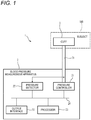
- FIG. 1 illustrates the functional configuration of a blood pressure measurement system 1 of an embodiment.
- the blood pressure measurement system 1 may include a blood pressure measurement apparatus 2 and a cuff 3.
- the blood pressure measurement apparatus 2 is an apparatus that measures the blood pressure of a subject 100 by using the cuff 3 which is attached to the subject.
- the blood pressure measurement apparatus 2 is an example of the venous pressure measurement apparatus. That is, the blood pressure measurement apparatus 2 may measure only the venous pressure of the subject, or may measure the artery pressure in addition to the venous pressure.
- the blood pressure measurement apparatus 2 may include a pressure controller 21, a pressure detector 22, a processor 23, and a communication bus 24.
- the pressure controller 21 is connected to the cuff 3 through a tube 31.
- the pressure controller 21 may include a pump mechanism and a valve mechanism.
- the pump mechanism feeds the air into the cuff 3 through the tube 31 to raise the internal pressure of the cuff 3.
- the valve mechanism makes or breaks communication between the tube 31 and the ambient air. When the tube 31 and the ambient air are communicated with each other during non-operation of the pump mechanism, the internal pressure of the cuff 3 is lowered.
- the pressure detector 22 detects the internal pressure of the cuff 3.
- the pressure detector 22 may include, for example, a pressure sensor that detects the internal pressure of the cuff 3 through the tube 31.
- the processor 23 can communicate signals and date with the pressure controller 21 and the pressure detector 22 through the communication bus 24.
- Each of the pressure controller 21 and the pressure detector 22 may appropriately include an interface circuit such as an A/D converter in order to provide signals and date having forms that can be processed by the processor 23.
- FIG. 2 illustrates an example of the flow of processes that are performed by the processor 23.
- the processor 23 causes the pressure controller 21 to stepwisely lower the internal pressure of the cuff 3 (STEP 11). That is, the pressure controller 21 performs a pressure control so that a state where the internal pressure of the cuff 3 has one of a plurality of setting values is continued for a predetermined time period, and, after the predetermined time period elapses, the internal pressure of the cuff 3 has one of a plurality of lower setting values.
- FIG. 3A illustrates an example of a change over time of the internal pressure of the cuff 3 that is detected by the pressure detector 22.
- the pressure controller 21 performs a pressure control so that the internal pressure of the cuff 3 is stepwisely lowered among 12 setting values.
- the waveform of FIG. 3A illustrating a change over time of the internal pressure of the cuff 3 contains vibration waveforms having frequency components that are higher as compared with the stepwise lowering of the internal pressure.
- the vibration waveforms reflect the pressure vibration (oscillation) that occurs in the cuff 3 in accordance with pulsations of the subject 100.
- FIG. 3B illustrates a change over time of the oscillation component that is extracted from the waveform of FIG. 3A illustrating a change over time of the internal pressure of the cuff 3.
- the extraction of the oscillation component may be performed by applying a frequency filtering process to the waveform of FIG. 3A .
- the frequency filtering process may be performed by causing the waveform to be passed through a high-pass filter circuit that may be provided in the pressure detector 22, or in a software-like manner by the processor 23.
- a plurality of oscillation waveforms are contained.
- the duration time period of a state where the internal pressure of the cuff 3 has one of the plurality of setting values is determined so as that a plurality of oscillation waveforms are contained within the time period.
- the processor 23 acquires a statistical value relating to the distribution of the amplitudes of a plurality of oscillation waveforms (STEP 12 of FIG. 2 ). In other words, the processor 23 acquires a statistical value relating to the distribution of the amplitudes of a plurality of pressure changes corresponding to pressure vibration that occurs in the cuff 3, and that is detected by the pressure detector 22, in a state where the internal pressure of the cuff 3 is set to one of the plurality of setting values.
- FIG. 4A illustrates an example of the oscillation waveform extracted in the above-described process.
- the single oscillation waveform corresponds to pressure vibration that occurs in the cuff 3 in response to one pulsation.
- the amplitude A of the oscillation waveform may be defined, for example, as the difference between the minimum and maximum values of the pulse pressure in the rising portion of the waveform.
- Examples of the statistical value are the mean, median, and mode values of amplitudes A of a plurality of oscillation waveforms.
- the sum of squares or root mean square (RMS) of a plurality of oscillation waveforms from which the DC component is eliminated may be used as the statistical value reflecting the amplitude A.
- the sum of squares, the RMS, or the like may be calculated for each of oscillation waveforms, and then the mean, median, mode values, or the like of the values may be identified for a plurality of oscillation waveforms.
- Statistical values of two or more types may be acquired.
- the processor 23 determines whether the internal pressure of the cuff 3 is lowered to a predetermined value or not (STEP 13 of FIG. 2 ). If the internal pressure of the cuff 3 is not lowered to the value indicated by the reference numeral 12 in FIG. 3A (N in STEP 13 of FIG. 2 ), the process returns to STEP 11. The internal pressure of the cuff 3 is lowered to the next setting value, and, during a period when the setting value is maintained, the at least one statistical value is acquired for a plurality of oscillation waveforms corresponding to pressure vibration that occurs in the cuff 3, and that is detected by the pressure detector 22.
- the stepwise lowering of the internal pressure of the cuff 3 may be performed in parallel with the process of acquiring a statistical value.
- the internal pressure of the cuff 3 is stepwisely lowered every elapse of the predetermined time period
- the apparatus may be configured so that, when a predetermined number of oscillation waveforms are acquired, the internal pressure of the cuff 3 is lowered by one step.
- FIG. 4B illustrates a change of the acquired statistical value due to the stepwise lowering of the internal pressure of the cuff 3.
- the circular plots indicate the RMS of a plurality of oscillation waveforms corresponding to pressure vibration that occurs in the cuff 3, and that is detected by the pressure detector 22, in a state where the internal pressure of the cuff 3 is at one of the plurality of setting values.
- the step numbers of the abscissa correspond to the step numbers of the stepwise lowering that are attached to the waveforms illustrated in FIGS. 3A and 3B .
- Each of the square plots indicates the difference value between the RMS that is calculated in a certain step (one of the plurality of setting values), and the RMS that is calculated in the step which is previous to the pressure lowering in the certain step.
- the processor 23 estimates the venous pressure of the subject 100 based on a change of the acquired statistical value due to the stepwise lowering of the internal pressure of the cuff 3 (STEP 14 of FIG. 2 ).
- the above-described oscillation waveforms are detected by the pressure detector 22 as a phenomenon in which the artery pressure pulse wave and venous pressure pulse wave of the subject 100 are superimposed on each other. It is known that, when the internal pressure of the cuff 3 is lower than the mean artery pressure, the amplitude of the artery pressure pulse wave is monotonously reduced with lowering of the internal pressure of the cuff 3. It is further known that the amplitude of the venous pressure pulse wave is maximum in the case where the internal pressure of the cuff 3 is equal to the mean venous pressure of the subject 100.
- the inventor of the present invention has conceived that the internal pressure value of the cuff 3 at which the amplitude of the oscillation waveform is maximum is identified within the pressure range that seems to include the mean venous pressure, thereby enabling the venous pressure of the subject 100 to be accurately estimated by using the single cuff 3.
- the change of the RMS shows the maximal value in step number 6 of the stepwise pressure lowering, and that of the difference value between the RMSs shows the maximum value.
- the processor 23 estimates the setting value of the internal pressure of the cuff 3 corresponding to step number 6 of the stepwise pressure lowering, as the venous pressure of the subject 100.
- the venous pressure of the subject 100 can be accurately estimated. Moreover, the venous pressure of the subject 100 is estimated by using the statistical value relating to the distribution of the amplitudes of a plurality of oscillation waveforms, and therefore the influence of noises can be suppressed, and the accuracy of the estimation can be improved.
- the pressure controller 21 performs the control so that the internal pressure of the cuff 3 is stepwisely lowered. According to the configuration, a plurality of oscillation waveforms that are acquired under the same internal pressure condition are used in the statistical process, and therefore the increase of the computational load of the processor 23 can be suppressed.
- the pressure controller 21 may perform the control so that the internal pressure of the cuff 3 is continuously lowered.
- a plurality of time ranges or pressure ranges are set so that a plurality of oscillation waveforms are acquired in each range, and the above-described statistical value is acquired in each of the ranges.
- the venous pressure of the subject 100 may be estimated based on a change of the statistical value due to a change of the internal pressure of the cuff 3.
- the processor 23 may determine whether the change of the acquired statistical value is transient or not (STEP 16). It is determined whether the change is transient or not, based on the magnitude of the change of the statistical value before and after the appearance of the inflection point. If it is determined that the change of the statistical value is not transient (N in STEP 16), the processor 23 executes the above-described estimation of the venous pressure (STEP 14). If it is determined that the change of the statistical value is transient (Y in STEP 16), the processor 23 terminates the process or again preforms the measurement. Alternatively, the processor 23 eliminates the statistical value that is determined to be transient, and then executes the estimation of the venous pressure.
- the maximal value of the RMS appears in step number 6.
- the maximal value is obtained by significant rising from the value of the RMS that is acquired in step number 5.
- the value of the RMS exhibits a significant lowering in step number 7 as indicated by the broken line and the triangular symbols in the figure.
- the processor 23 determines that the change of the RMS containing the appearance of the maximal value in step number 6 is transient.
- the processor 23 may determine that the change of the RMS containing the appearance of the maximal value in step number 6 is not transient.
- the processor 23 may estimate a value that is smaller than the internal pressure of the cuff 3 at which the change of the statistical value indicates the inflection point, as the venous pressure of the subject 100.
- the internal pressure of the cuff 3 that corresponds to step number 7, and that is lowered by one step from the internal pressure of the cuff 3 corresponding to step number 6 in which the RMS exhibits the maximal value (or the difference value between the RMSs exhibits the maximum value) may be estimated as the venous pressure of the subject 100.
- a value that is smaller than the value of the internal pressure of the cuff 3 corresponding to the inflection point of the change of the statistical value which indicates the state where the amplitude of the oscillation waveform is maximum may sometimes reflect the mean venous pressure of the subject 100. According to the above-described configuration, in such a case, the venous pressure of the subject 100 can be accurately estimated.
- the internal pressure of the cuff 3 corresponding to a step number that is reduced by two or more steps may be employed as an estimated value, or a value that is obtained by uniformly reducing a predetermined value from the internal pressure of the cuff 3 at which the change of the statistical value indicates the inflection point may be employed as an estimated value.
- the blood pressure measurement apparatus 2 may further include an output interface 25.
- the output interface 25 can communicate signals and date with the processor 23 through the communication bus 24.
- the processor 23 causes the output interface 25 to output the estimated value of the venous pressure of the subject 100 as a measurement value (STEP 15 of FIG. 2 ).
- the output interface 25 may include at least one of: a display device that visually outputs the measurement value; a sound output device that audibly outputs the measurement value; and a port that outputs the measurement value to an external device as data.
- FIG. 5 illustrates another example of the flow of processes that are performed by the processor 23.
- the processes that are substantially identical with those illustrated in FIG. 2 are denoted by the same reference numerals, and the duplicated descriptions are omitted.
- the processor 23 acquires an index value that indicates the manner of the pressure change, for at least one oscillation waveform (STEP 22).
- the duration time period of a state where the internal pressure of the cuff 3 is at one of the plurality of setting values is determined so that at least one oscillation waveform is contained within the time period.
- the index value that indicates the manner of the pressure change i.e., the shape of the oscillation waveform
- the index value that indicates the manner of the pressure change are the maximum pressure value, the minimum pressure value, the mean pressure value, the amplitude, the sum of squares, the RMS, the dispersion, the gradient, the peakedness, the distortion, the percentile, and the like.
- the oscillation waveform is indicated as a change over time of a plurality of pressure values that are acquired at a predetermined sampling rate. These index values are acquired by using at least one of the plurality of acquired pressure values.
- the acquired index values may have two or more types.
- the index value may be the mean, median, or mode value of a plurality of index values acquired for a plurality of oscillation waveforms.
- the processor 23 determines whether the internal pressure of the cuff 3 is lowered to a predetermined value or not (STEP 23 of FIG. 5 ). If the internal pressure of the cuff 3 is not lowered to a value that is indicated by the reference numeral 12 illustrated in FIG. 3A (N in STEP 23 of FIG. 5 ), the process returns to STEP 11.
- the internal pressure of the cuff 3 is lowered to the next setting value, and, during a period when the setting value is maintained, the index value is acquired for at least one oscillation waveform corresponding to the pressure vibration that is detected by the pressure detector 22, and that occurs in the cuff 3.
- FIG. 6 illustrates the 25th percentile change of the oscillation waveform due to the stepwise lowering of the internal pressure of the cuff 3.
- the processor 23 estimates the venous pressure of the subject 100 based on a change of the acquired index value due to the stepwise lowering of the internal pressure of the cuff 3 (STEP 24 of FIG. 5 ).
- the above-described oscillation waveforms are detected by the pressure detector 22 as a phenomenon in which the artery pressure pulse wave and venous pressure pulse wave of the subject 100 are superimposed on each other. It is known that, when the internal pressure of the cuff 3 is lower than the mean artery pressure, the amplitude of the artery pressure pulse wave is monotonously reduced with lowering of the internal pressure of the cuff 3. It is further known that the amplitude of the venous pressure pulse wave is maximum in the case where the internal pressure of the cuff 3 is equal to the mean venous pressure of the subject 100. It is still further known that the artery pressure pulse wave and the venous pressure pulse wave are different in phase and shape from each other.
- the inventor of the present invention has conceived that, when the internal pressure of the cuff 3 coincides with the mean venous pressure, the shape of the oscillation waveform exhibits a significant change.
- the inventor of the present invention has conceived that, when the value of the internal pressure of the cuff 3 at which a change of an index value that indicates the shape of the oscillation waveform is identified within the pressure range that seems to include the mean venous pressure, the venous pressure of the subject 100 can be accurately estimated by using the single cuff 3.
- step number 6 of the stepwise pressure lowering the 25th percentile change shows a significant minimal value.
- the processor 23 estimates the setting value of the internal pressure of the cuff 3 corresponding to step number 6 of the stepwise pressure lowering, as the venous pressure of the subject 100.
- the combination of the index value and the inflection point can be appropriately determined.
- the maximal value attracts attention as the inflection point that reflects the state where the shape change of the oscillation waveform is significant.
- the processor 23 estimates the setting value of the internal pressure of the cuff 3 at which the 75th percentile change exhibits the maximal value, as the venous pressure of the subject 100.
- the venous pressure of the subject 100 can be accurately estimated.
- the venous pressure can be estimated based on at least one pressure vibration that occurs in the cuff 3, and therefore the measurement can be made faster.
- the stepwise lowering of the internal pressure of the cuff 3 may be performed in parallel with the process of acquiring a statistical value.
- the pressure controller 21 may perform the control so that the internal pressure of the cuff 3 is continuously lowered.
- a plurality of oscillation waveforms are detected, and the above-described index value is acquired for each of the oscillation waveforms.
- the venous pressure of the subject 100 may be estimated based on a change of the index value due to a change of the internal pressure of the cuff 3.
- the processor 23 may determine whether the change of the acquired index value is transient or not (STEP 26). It is determined whether the change is transient or not, based on the magnitude of the change of the index value before and after the appearance of the inflection point. If it is determined that the change of the index value is not transient (N in STEP 26), the processor 23 executes the above-described estimation of the venous pressure (STEP 24). If it is determined that the change of the index value is transient (Y in STEP 26), the processor 23 terminates the process or again preforms the measurement. Alternatively, the processor 23 eliminates the index value that is determined to be transient, and then executes the estimation of the venous pressure.
- the 25th percentile minimal value appears in step number 6.
- the minimal value is obtained by significant lowering from the 25th percentile value that is acquired in step number 5.
- the 25th percentile value exhibits a significant rising in step number 7 as indicated by the broken line and the triangular symbols in the figure.
- the processor 23 determines that the 25th percentile change containing the appearance of the minimal value in step number 6 is transient.
- the processor 23 may determine that the 25th percentile change containing the appearance of the minimal value in step number 6 is not transient.
- the processor 23 may estimate a value that is smaller than the internal pressure of the cuff 3 at which the change of the index value indicates the inflection point, as the venous pressure of the subject 100.
- the internal pressure of the cuff 3 that corresponds to step number 7, and that is lowered by one step from the internal pressure of the cuff 3 corresponding to step number 6 in which the25th percentile exhibits the significant minimal value may be estimated as the venous pressure of the subject 100.
- a value that is smaller than the value of the internal pressure of the cuff 3 corresponding to the inflection point of the change of the index value which indicates the state where the amplitude of the oscillation waveform is maximum may sometimes reflect the mean venous pressure of the subject 100. According to the above-described configuration, in such a case, the venous pressure of the subject 100 can be accurately estimated.
- the internal pressure of the cuff 3 corresponding to a step number that is reduced by two or more steps may be employed as an estimated value, or a value that is obtained by uniformly reducing a predetermined value from the internal pressure of the cuff 3 at which the change of the index value indicates the inflection point may be employed as an estimated value.
- the above-described function of the processor 23 may be realized by a general-purpose microprocessor which operates in cooperation with a general-purpose memory.
- Examples of such a general-purpose microprocessor are a CPU, an MPU, and a GPU.
- Examples of such a general-purpose memory are a RAM and a ROM.
- a ROM may store programs that execute the above-described processes.
- the programs may include an artificial intelligence program.
- An example of an artificial intelligence program is a learned neural network with deep learning.
- the general-purpose microprocessor may designate at least part of the programs stored in the ROM, load the designated programs into the RAM, and execute the above-described processes in cooperation with the RAM.
- the above-described function of the processor 23 may be realized by a dedicated integrated circuit such as a microcontroller, an FPGA, or an ASIC. At least part of the function of the processor 23 may be realized by a calculating device of a computer to which the blood pressure measurement apparatus 2 is connected.
- the processor 23 estimates the venous pressure of the subject 100 while causing the pressure controller 21 to lower the internal pressure of the cuff 3.
- the embodiment may be easily integrated with a depressurization artery pressure measurement apparatus that is more prevalent. After the artery pressure is measured while the internal pressure of the cuff 3 is lowered in a higher numerical range, the measurement of the venous pressure can be efficiently performed.
- the processor 23 may estimate the venous pressure of the subject 100 while causing the pressure controller 21 to raise the internal pressure of the cuff 3. Namely, the processor 23 may cause the pressure controller 21 to stepwisely change (lower or raise) the internal pressure of the cuff 3 or to continuously change (lower or raise) the internal pressure of the cuff 3.
- the processor 23 may employ a value that is lower than the internal pressure of the cuff 3 at which a change of the statistical value or index value that is acquired indicates the inflection point, as an estimated value of the venous pressure.
- a value at which these values indicate the inflection point, or a value that is higher than the internal pressure of the cuff 3 at which the value indicates the inflection point may be employed as an estimated value of the venous pressure.
- a venous pressure measurement apparatus including: a pressure controller that causes an internal pressure of a cuff to be attached to a subject, to change; a pressure detector that detects the internal pressure of the cuff; and a processor that causes the pressure controller to change the internal pressure of the cuff, acquires a statistical value relating to a distribution of amplitudes of a plurality of pressure changes corresponding to pressure vibration that occurs in the cuff, and that is detected by the pressure detector, and estimates a venous pressure of the subject based on a change of the statistical value due to the change of the internal pressure of the cuff.
- the pressure vibration that occurs in the cuff is detected by the pressure detector as a phenomenon in which the artery pressure pulse wave and venous pressure pulse wave of the subject are superimposed on each other. It is known that, when the internal pressure of the cuff is lower than the mean artery pressure, the amplitude of the artery pressure pulse wave is monotonously reduced with lowering of the internal pressure of the cuff. It is further known that the amplitude of the venous pressure pulse wave is maximum in the case where the internal pressure of the cuff is equal to the mean venous pressure of the subject.
- the inventor of the present invention has conceived that the internal pressure value of a cuff at which the amplitude of the pressure vibration is maximum is identified within a pressure range that seems to include the mean venous pressure, thereby enabling the venous pressure of the subject to be accurately estimated by using the single cuff.
- the maximal value may appear in change of the value of the root mean square of a plurality of pressure vibrations.
- the value reflects the state where the amplitude of the pressure vibration is maximum.
- the processor estimates the internal pressure of the cuff when the maximal value appears, as the venous pressure of the subject.
- the venous pressure of the subject can be accurately estimated. Moreover, the venous pressure of the subject is estimated by using the statistical value relating to the distribution of the amplitudes of a plurality of pressure vibrations, and therefore the influence of noises can be suppressed, and the accuracy of the estimation can be improved.
- a venous pressure measurement apparatus including: a pressure controller that causes an internal pressure of a cuff which is attached to a subject, to change; a pressure detector that detects the internal pressure of the cuff; and a processor that causes the pressure controller to change the internal pressure of the cuff, acquires an index value indicating a manner of a pressure change corresponding to pressure vibration that occurs in the cuff, and that is detected by the pressure detector, and estimates a venous pressure of the subject based on a change of the index value due to the change of the internal pressure of the cuff.
- the pressure vibration that occurs in the cuff is detected by the pressure detector as a phenomenon in which the artery pressure pulse wave and venous pressure pulse wave of the subject are superimposed on each other. It is known that the amplitude of the artery pressure pulse wave when the internal pressure of the cuff is lower than the mean artery pressure is monotonously reduced with lowering the internal pressure of the cuff. It is known that the amplitude of the venous pressure pulse wave is maximum in the case where the internal pressure of the cuff is equal to the mean venous pressure. It is further known that the artery pressure pulse wave and the venous pressure pulse wave are different in phase and shape from each other.
- the inventor of the present invention has conceived that, when the internal pressure of the cuff coincides with the mean venous pressure, the shape of a waveform corresponding to the pressure vibration exhibits a significant change.
- the inventor of the present invention has conceived that, when the value of the internal pressure of the cuff at which a change of the index value that indicates the shape of a waveform corresponding to the pressure vibration is identified within the pressure range that seems to include the mean venous pressure, the venous pressure of the subject can be accurately estimated by using the single cuff.
- the 25th percentile change can show a significant minimal value.
- the value reflects the state where a shape change of a waveform corresponding to a pressure vibration is significant.
- the processor estimates the internal pressure of the cuff when the minimal value appears, as the venous pressure of the subject.
- the venous pressure of the subject can be accurately estimated.
- the venous pressure can be estimated based on at least one pressure vibration that occurs in the cuff, and therefore the measurement can be made faster.
Landscapes
- Health & Medical Sciences (AREA)
- Life Sciences & Earth Sciences (AREA)
- Cardiology (AREA)
- Vascular Medicine (AREA)
- Heart & Thoracic Surgery (AREA)
- Medical Informatics (AREA)
- Biophysics (AREA)
- Pathology (AREA)
- Engineering & Computer Science (AREA)
- Biomedical Technology (AREA)
- Physiology (AREA)
- Physics & Mathematics (AREA)
- Molecular Biology (AREA)
- Surgery (AREA)
- Animal Behavior & Ethology (AREA)
- General Health & Medical Sciences (AREA)
- Public Health (AREA)
- Veterinary Medicine (AREA)
- Ophthalmology & Optometry (AREA)
- Measuring Pulse, Heart Rate, Blood Pressure Or Blood Flow (AREA)
Abstract
Description
- The presently disclosed subject matter relates to an apparatus that measures the venous pressure by using a cuff which is attached to the subject.
- Japanese Patent No.
5,694,032 - A pulse wave signal corresponding to the second pressure vibration may be acquired also by another sensor that is different from the first cuff which is attached to the finger tip of the subject.
- It is an object of the presently disclosed subject matter to provide an apparatus that can accurately estimate the venous pressure of the subject although using a single cuff.
- According to an aspect of the presently disclosed subject matter, there is provided a venous pressure measurement apparatus including: a pressure controller that causes an internal pressure of a cuff to be attached to a subject, to change; a pressure detector that detects the internal pressure of the cuff; and a processor that causes the pressure controller to change the internal pressure of the cuff, acquires a statistical value relating to a distribution of amplitudes of a plurality of pressure changes corresponding to pressure vibration that occurs in the cuff, and that is detected by the pressure detector, and estimates a venous pressure of the subject based on a change of the statistical value due to the change of the internal pressure of the cuff.
- According to an aspect of the presently disclosed subject matter, there is also provided a venous pressure measurement apparatus including: a pressure controller that causes an internal pressure of a cuff which is attached to a subject, to change; a pressure detector that detects the internal pressure of the cuff; and a processor that causes the pressure controller to change the internal pressure of the cuff, acquires an index value indicating a manner of a pressure change corresponding to pressure vibration that occurs in the cuff, and that is detected by the pressure detector, and estimates a venous pressure of the subject based on a change of the index value due to the change of the internal pressure of the cuff.
-
-
FIG. 1 illustrates the functional configuration of a blood pressure measurement system of an embodiment. -
FIG. 2 illustrates an operation example of a blood pressure measurement apparatus inFIG. 1 . -
FIGS. 3A and 3B illustrate an estimation of the venous pressure based on the operation ofFIG. 2 . -
FIGS. 4A and 4B illustrate an estimation of the venous pressure based on the operation ofFIG. 2 . -
FIG. 5 illustrates another operation example of the blood pressure measurement apparatus inFIG. 1 . -
FIG. 6 illustrates an estimation of the venous pressure based on the operation ofFIG. 5 . - Hereinafter, an embodiment will be described in detail with reference to the accompanying drawings.
FIG. 1 illustrates the functional configuration of a bloodpressure measurement system 1 of an embodiment. The bloodpressure measurement system 1 may include a bloodpressure measurement apparatus 2 and acuff 3. - The blood
pressure measurement apparatus 2 is an apparatus that measures the blood pressure of asubject 100 by using thecuff 3 which is attached to the subject. The bloodpressure measurement apparatus 2 is an example of the venous pressure measurement apparatus. That is, the bloodpressure measurement apparatus 2 may measure only the venous pressure of the subject, or may measure the artery pressure in addition to the venous pressure. - The blood
pressure measurement apparatus 2 may include apressure controller 21, apressure detector 22, aprocessor 23, and acommunication bus 24. - The
pressure controller 21 is connected to thecuff 3 through atube 31. Thepressure controller 21 may include a pump mechanism and a valve mechanism. The pump mechanism feeds the air into thecuff 3 through thetube 31 to raise the internal pressure of thecuff 3. The valve mechanism makes or breaks communication between thetube 31 and the ambient air. When thetube 31 and the ambient air are communicated with each other during non-operation of the pump mechanism, the internal pressure of thecuff 3 is lowered. - The
pressure detector 22 detects the internal pressure of thecuff 3. Thepressure detector 22 may include, for example, a pressure sensor that detects the internal pressure of thecuff 3 through thetube 31. - The
processor 23 can communicate signals and date with thepressure controller 21 and thepressure detector 22 through thecommunication bus 24. Each of thepressure controller 21 and thepressure detector 22 may appropriately include an interface circuit such as an A/D converter in order to provide signals and date having forms that can be processed by theprocessor 23. -
FIG. 2 illustrates an example of the flow of processes that are performed by theprocessor 23. Theprocessor 23 causes thepressure controller 21 to stepwisely lower the internal pressure of the cuff 3 (STEP 11). That is, thepressure controller 21 performs a pressure control so that a state where the internal pressure of thecuff 3 has one of a plurality of setting values is continued for a predetermined time period, and, after the predetermined time period elapses, the internal pressure of thecuff 3 has one of a plurality of lower setting values. -
FIG. 3A illustrates an example of a change over time of the internal pressure of thecuff 3 that is detected by thepressure detector 22. In the example, thepressure controller 21 performs a pressure control so that the internal pressure of thecuff 3 is stepwisely lowered among 12 setting values. - The waveform of
FIG. 3A illustrating a change over time of the internal pressure of thecuff 3 contains vibration waveforms having frequency components that are higher as compared with the stepwise lowering of the internal pressure. The vibration waveforms reflect the pressure vibration (oscillation) that occurs in thecuff 3 in accordance with pulsations of thesubject 100. -
FIG. 3B illustrates a change over time of the oscillation component that is extracted from the waveform ofFIG. 3A illustrating a change over time of the internal pressure of thecuff 3. The extraction of the oscillation component may be performed by applying a frequency filtering process to the waveform ofFIG. 3A . The frequency filtering process may be performed by causing the waveform to be passed through a high-pass filter circuit that may be provided in thepressure detector 22, or in a software-like manner by theprocessor 23. - As illustrated in
FIG. 3B , during a period when the state where the internal pressure of thecuff 3 has one of the plurality of setting values is continued, a plurality of oscillation waveforms are contained. In other words, the duration time period of a state where the internal pressure of thecuff 3 has one of the plurality of setting values is determined so as that a plurality of oscillation waveforms are contained within the time period. - Then, the
processor 23 acquires a statistical value relating to the distribution of the amplitudes of a plurality of oscillation waveforms (STEP 12 ofFIG. 2 ). In other words, theprocessor 23 acquires a statistical value relating to the distribution of the amplitudes of a plurality of pressure changes corresponding to pressure vibration that occurs in thecuff 3, and that is detected by thepressure detector 22, in a state where the internal pressure of thecuff 3 is set to one of the plurality of setting values. -
FIG. 4A illustrates an example of the oscillation waveform extracted in the above-described process. The single oscillation waveform corresponds to pressure vibration that occurs in thecuff 3 in response to one pulsation. The amplitude A of the oscillation waveform may be defined, for example, as the difference between the minimum and maximum values of the pulse pressure in the rising portion of the waveform. - Examples of the statistical value are the mean, median, and mode values of amplitudes A of a plurality of oscillation waveforms. Alternatively, the sum of squares or root mean square (RMS) of a plurality of oscillation waveforms from which the DC component is eliminated may be used as the statistical value reflecting the amplitude A. The sum of squares, the RMS, or the like may be calculated for each of oscillation waveforms, and then the mean, median, mode values, or the like of the values may be identified for a plurality of oscillation waveforms. Statistical values of two or more types may be acquired.
- When at least one statistical value is acquired, the
processor 23 determines whether the internal pressure of thecuff 3 is lowered to a predetermined value or not (STEP 13 ofFIG. 2 ). If the internal pressure of thecuff 3 is not lowered to the value indicated by thereference numeral 12 inFIG. 3A (N in STEP 13 ofFIG. 2 ), the process returns to STEP 11. The internal pressure of thecuff 3 is lowered to the next setting value, and, during a period when the setting value is maintained, the at least one statistical value is acquired for a plurality of oscillation waveforms corresponding to pressure vibration that occurs in thecuff 3, and that is detected by thepressure detector 22. - The stepwise lowering of the internal pressure of the
cuff 3 may be performed in parallel with the process of acquiring a statistical value. Although, in the above example, the internal pressure of thecuff 3 is stepwisely lowered every elapse of the predetermined time period, the apparatus may be configured so that, when a predetermined number of oscillation waveforms are acquired, the internal pressure of thecuff 3 is lowered by one step. -
FIG. 4B illustrates a change of the acquired statistical value due to the stepwise lowering of the internal pressure of thecuff 3. The circular plots indicate the RMS of a plurality of oscillation waveforms corresponding to pressure vibration that occurs in thecuff 3, and that is detected by thepressure detector 22, in a state where the internal pressure of thecuff 3 is at one of the plurality of setting values. The step numbers of the abscissa correspond to the step numbers of the stepwise lowering that are attached to the waveforms illustrated inFIGS. 3A and 3B . Each of the square plots indicates the difference value between the RMS that is calculated in a certain step (one of the plurality of setting values), and the RMS that is calculated in the step which is previous to the pressure lowering in the certain step. - When the internal pressure of the
cuff 3 is lowered to the value indicated by thereference numeral 12 inFIG. 3A (Y in STEP 13 ofFIG. 2 ), theprocessor 23 estimates the venous pressure of the subject 100 based on a change of the acquired statistical value due to the stepwise lowering of the internal pressure of the cuff 3 (STEP 14 ofFIG. 2 ). - The above-described oscillation waveforms are detected by the
pressure detector 22 as a phenomenon in which the artery pressure pulse wave and venous pressure pulse wave of the subject 100 are superimposed on each other. It is known that, when the internal pressure of thecuff 3 is lower than the mean artery pressure, the amplitude of the artery pressure pulse wave is monotonously reduced with lowering of the internal pressure of thecuff 3. It is further known that the amplitude of the venous pressure pulse wave is maximum in the case where the internal pressure of thecuff 3 is equal to the mean venous pressure of the subject 100. The inventor of the present invention has conceived that the internal pressure value of thecuff 3 at which the amplitude of the oscillation waveform is maximum is identified within the pressure range that seems to include the mean venous pressure, thereby enabling the venous pressure of the subject 100 to be accurately estimated by using thesingle cuff 3. - In the example illustrated in
FIG. 4B , the change of the RMS shows the maximal value instep number 6 of the stepwise pressure lowering, and that of the difference value between the RMSs shows the maximum value. These values appear in the change of the statistical value as the inflection point that reflects the state where the amplitude of the oscillation waveform is maximum. In the example, theprocessor 23 estimates the setting value of the internal pressure of thecuff 3 corresponding to stepnumber 6 of the stepwise pressure lowering, as the venous pressure of the subject 100. - According to the configuration, while using the single cuff 3 (without attaching an additional cuff or sensor to the subject 100), the venous pressure of the subject 100 can be accurately estimated. Moreover, the venous pressure of the subject 100 is estimated by using the statistical value relating to the distribution of the amplitudes of a plurality of oscillation waveforms, and therefore the influence of noises can be suppressed, and the accuracy of the estimation can be improved.
- In the embodiment, the
pressure controller 21 performs the control so that the internal pressure of thecuff 3 is stepwisely lowered. According to the configuration, a plurality of oscillation waveforms that are acquired under the same internal pressure condition are used in the statistical process, and therefore the increase of the computational load of theprocessor 23 can be suppressed. - Alternatively, the
pressure controller 21 may perform the control so that the internal pressure of thecuff 3 is continuously lowered. In the alternative, a plurality of time ranges or pressure ranges are set so that a plurality of oscillation waveforms are acquired in each range, and the above-described statistical value is acquired in each of the ranges. Also in such a configuration, the venous pressure of the subject 100 may be estimated based on a change of the statistical value due to a change of the internal pressure of thecuff 3. - As illustrated in
FIG. 2 , theprocessor 23 may determine whether the change of the acquired statistical value is transient or not (STEP 16). It is determined whether the change is transient or not, based on the magnitude of the change of the statistical value before and after the appearance of the inflection point. If it is determined that the change of the statistical value is not transient (N in STEP 16), theprocessor 23 executes the above-described estimation of the venous pressure (STEP 14). If it is determined that the change of the statistical value is transient (Y in STEP 16), theprocessor 23 terminates the process or again preforms the measurement. Alternatively, theprocessor 23 eliminates the statistical value that is determined to be transient, and then executes the estimation of the venous pressure. This is performed because, in the case where the change of the statistical value is transient, there is a high possibility that this change may be caused by noises containing an arrhythmia. According to the configuration, therefore, reduction of the accuracy of the measurement of the venous pressure that is due to an influence of noises containing an arrhythmia can be suppressed. - In the case of the example illustrated in
FIG. 4B , the maximal value of the RMS appears instep number 6. The maximal value is obtained by significant rising from the value of the RMS that is acquired instep number 5. In the case where the significant rising of the value is caused by noises and transient, the value of the RMS exhibits a significant lowering instep number 7 as indicated by the broken line and the triangular symbols in the figure. In the case where the value is smaller than the value of the RMS that is acquired instep number 5, or the lowering amount of the value is larger than a predetermined value, theprocessor 23 determines that the change of the RMS containing the appearance of the maximal value instep number 6 is transient. - By contrast, in the case where the change of the RMS is normal, the value of the RMS that is acquired in
step number 7 is larger than the value of the RMS that is acquired instep number 5, or the lowering amount of the value is equal to or smaller than the predetermined value. In the case where such a change is confirmed at least one time after the appearance of the maximal value, theprocessor 23 may determine that the change of the RMS containing the appearance of the maximal value instep number 6 is not transient. - The
processor 23 may estimate a value that is smaller than the internal pressure of thecuff 3 at which the change of the statistical value indicates the inflection point, as the venous pressure of the subject 100. In the example illustrated inFIG. 4B , the internal pressure of thecuff 3 that corresponds to stepnumber 7, and that is lowered by one step from the internal pressure of thecuff 3 corresponding to stepnumber 6 in which the RMS exhibits the maximal value (or the difference value between the RMSs exhibits the maximum value) may be estimated as the venous pressure of the subject 100. - Since the artery pressure pulse wave that is superimposed on the oscillation waveform is monotonously reduced with the pressure lowering of the
cuff 3, a value that is smaller than the value of the internal pressure of thecuff 3 corresponding to the inflection point of the change of the statistical value which indicates the state where the amplitude of the oscillation waveform is maximum may sometimes reflect the mean venous pressure of the subject 100. According to the above-described configuration, in such a case, the venous pressure of the subject 100 can be accurately estimated. - In the case where the change of the statistical value is smaller than the internal pressure of the
cuff 3 indicating the inflection point, the internal pressure of thecuff 3 corresponding to a step number that is reduced by two or more steps may be employed as an estimated value, or a value that is obtained by uniformly reducing a predetermined value from the internal pressure of thecuff 3 at which the change of the statistical value indicates the inflection point may be employed as an estimated value. - As illustrated in
FIG. 1 , the bloodpressure measurement apparatus 2 may further include anoutput interface 25. Theoutput interface 25 can communicate signals and date with theprocessor 23 through thecommunication bus 24. Theprocessor 23 causes theoutput interface 25 to output the estimated value of the venous pressure of the subject 100 as a measurement value (STEP 15 ofFIG. 2 ). - The
output interface 25 may include at least one of: a display device that visually outputs the measurement value; a sound output device that audibly outputs the measurement value; and a port that outputs the measurement value to an external device as data. -
FIG. 5 illustrates another example of the flow of processes that are performed by theprocessor 23. The processes that are substantially identical with those illustrated inFIG. 2 are denoted by the same reference numerals, and the duplicated descriptions are omitted. - In the example, the
processor 23 acquires an index value that indicates the manner of the pressure change, for at least one oscillation waveform (STEP 22). The duration time period of a state where the internal pressure of thecuff 3 is at one of the plurality of setting values is determined so that at least one oscillation waveform is contained within the time period. Examples of the index value that indicates the manner of the pressure change (i.e., the shape of the oscillation waveform) are the maximum pressure value, the minimum pressure value, the mean pressure value, the amplitude, the sum of squares, the RMS, the dispersion, the gradient, the peakedness, the distortion, the percentile, and the like. The oscillation waveform is indicated as a change over time of a plurality of pressure values that are acquired at a predetermined sampling rate. These index values are acquired by using at least one of the plurality of acquired pressure values. The acquired index values may have two or more types. The index value may be the mean, median, or mode value of a plurality of index values acquired for a plurality of oscillation waveforms. - When the index value is acquired, the
processor 23 determines whether the internal pressure of thecuff 3 is lowered to a predetermined value or not (STEP 23 ofFIG. 5 ). If the internal pressure of thecuff 3 is not lowered to a value that is indicated by thereference numeral 12 illustrated inFIG. 3A (N inSTEP 23 ofFIG. 5 ), the process returns to STEP 11. The internal pressure of thecuff 3 is lowered to the next setting value, and, during a period when the setting value is maintained, the index value is acquired for at least one oscillation waveform corresponding to the pressure vibration that is detected by thepressure detector 22, and that occurs in thecuff 3.FIG. 6 illustrates the 25th percentile change of the oscillation waveform due to the stepwise lowering of the internal pressure of thecuff 3. - If the internal pressure of the
cuff 3 is lowered to the value indicated by thereference numeral 12 inFIG. 3A (Y inSTEP 23 ofFIG. 5 ), theprocessor 23 estimates the venous pressure of the subject 100 based on a change of the acquired index value due to the stepwise lowering of the internal pressure of the cuff 3 (STEP 24 ofFIG. 5 ). - The above-described oscillation waveforms are detected by the
pressure detector 22 as a phenomenon in which the artery pressure pulse wave and venous pressure pulse wave of the subject 100 are superimposed on each other. It is known that, when the internal pressure of thecuff 3 is lower than the mean artery pressure, the amplitude of the artery pressure pulse wave is monotonously reduced with lowering of the internal pressure of thecuff 3. It is further known that the amplitude of the venous pressure pulse wave is maximum in the case where the internal pressure of thecuff 3 is equal to the mean venous pressure of the subject 100. It is still further known that the artery pressure pulse wave and the venous pressure pulse wave are different in phase and shape from each other. The inventor of the present invention has conceived that, when the internal pressure of thecuff 3 coincides with the mean venous pressure, the shape of the oscillation waveform exhibits a significant change. The inventor of the present invention has conceived that, when the value of the internal pressure of thecuff 3 at which a change of an index value that indicates the shape of the oscillation waveform is identified within the pressure range that seems to include the mean venous pressure, the venous pressure of the subject 100 can be accurately estimated by using thesingle cuff 3. - In an example illustrated in
FIG. 6 , instep number 6 of the stepwise pressure lowering, the 25th percentile change shows a significant minimal value. The value appears in the change of the index value as the inflection point that reflects the state where the shape change of the oscillation waveform is significant. In the example, theprocessor 23 estimates the setting value of the internal pressure of thecuff 3 corresponding to stepnumber 6 of the stepwise pressure lowering, as the venous pressure of the subject 100. - The combination of the index value and the inflection point can be appropriately determined. In the case where the 75th percentile of the oscillation waveform is used as the index value, for example, the maximal value attracts attention as the inflection point that reflects the state where the shape change of the oscillation waveform is significant. In this case, the
processor 23 estimates the setting value of the internal pressure of thecuff 3 at which the 75th percentile change exhibits the maximal value, as the venous pressure of the subject 100. - Also according to the configuration, although using the single cuff 3 (without attaching an additional cuff or sensor to the subject 100), the venous pressure of the subject 100 can be accurately estimated. Moreover, the venous pressure can be estimated based on at least one pressure vibration that occurs in the
cuff 3, and therefore the measurement can be made faster. - The stepwise lowering of the internal pressure of the
cuff 3 may be performed in parallel with the process of acquiring a statistical value. Alternatively, thepressure controller 21 may perform the control so that the internal pressure of thecuff 3 is continuously lowered. In the alternative, during a period when the internal pressure of thecuff 3 is continuously lowered to the predetermined value, a plurality of oscillation waveforms are detected, and the above-described index value is acquired for each of the oscillation waveforms. Also according to the configuration, the venous pressure of the subject 100 may be estimated based on a change of the index value due to a change of the internal pressure of thecuff 3. - As illustrated in
FIG. 5 , theprocessor 23 may determine whether the change of the acquired index value is transient or not (STEP 26). It is determined whether the change is transient or not, based on the magnitude of the change of the index value before and after the appearance of the inflection point. If it is determined that the change of the index value is not transient (N in STEP 26), theprocessor 23 executes the above-described estimation of the venous pressure (STEP 24). If it is determined that the change of the index value is transient (Y in STEP 26), theprocessor 23 terminates the process or again preforms the measurement. Alternatively, theprocessor 23 eliminates the index value that is determined to be transient, and then executes the estimation of the venous pressure. This is performed because, in the case where the change of the index value is transient, there is a high possibility that this change may be caused by noises containing an arrhythmia. According to the configuration, therefore, reduction of the accuracy of the measurement of the venous pressure that is due to an influence of noises containing an arrhythmia can be suppressed. - In the case of the example illustrated in
FIG. 6 , the 25th percentile minimal value appears instep number 6. The minimal value is obtained by significant lowering from the 25th percentile value that is acquired instep number 5. In the case where the significant lowering of the value is caused by noises and transient, the 25th percentile value exhibits a significant rising instep number 7 as indicated by the broken line and the triangular symbols in the figure. When the rising value is larger than a predetermined value, theprocessor 23 determines that the 25th percentile change containing the appearance of the minimal value instep number 6 is transient. - By contrast, in the case where the 25th percentile change is normal, the rising amount of the 25th percentile value that is acquired in
step number 7, from the minimal value is equal to or smaller than the predetermined value. In the case where such a change is confirmed at least one time after the appearance of the minimal value, theprocessor 23 may determine that the 25th percentile change containing the appearance of the minimal value instep number 6 is not transient. - The
processor 23 may estimate a value that is smaller than the internal pressure of thecuff 3 at which the change of the index value indicates the inflection point, as the venous pressure of the subject 100. In the example illustrated inFIG. 6 , the internal pressure of thecuff 3 that corresponds to stepnumber 7, and that is lowered by one step from the internal pressure of thecuff 3 corresponding to stepnumber 6 in which the25th percentile exhibits the significant minimal value may be estimated as the venous pressure of the subject 100. - Since the artery pressure pulse wave that is superimposed on the oscillation waveform is monotonously reduced with the pressure lowering of the
cuff 3, a value that is smaller than the value of the internal pressure of thecuff 3 corresponding to the inflection point of the change of the index value which indicates the state where the amplitude of the oscillation waveform is maximum may sometimes reflect the mean venous pressure of the subject 100. According to the above-described configuration, in such a case, the venous pressure of the subject 100 can be accurately estimated. - In the case where the change of the index value is smaller than the internal pressure of the
cuff 3 indicating the inflection point, the internal pressure of thecuff 3 corresponding to a step number that is reduced by two or more steps may be employed as an estimated value, or a value that is obtained by uniformly reducing a predetermined value from the internal pressure of thecuff 3 at which the change of the index value indicates the inflection point may be employed as an estimated value. - The above-described function of the
processor 23 may be realized by a general-purpose microprocessor which operates in cooperation with a general-purpose memory. Examples of such a general-purpose microprocessor are a CPU, an MPU, and a GPU. Examples of such a general-purpose memory are a RAM and a ROM. A ROM may store programs that execute the above-described processes. The programs may include an artificial intelligence program. An example of an artificial intelligence program is a learned neural network with deep learning. The general-purpose microprocessor may designate at least part of the programs stored in the ROM, load the designated programs into the RAM, and execute the above-described processes in cooperation with the RAM. - The above-described function of the
processor 23 may be realized by a dedicated integrated circuit such as a microcontroller, an FPGA, or an ASIC. At least part of the function of theprocessor 23 may be realized by a calculating device of a computer to which the bloodpressure measurement apparatus 2 is connected. - The above-described embodiment is a mere example for facilitating understanding of the presently disclosed subject matter. The configuration of the embodiment may be adequately changed or improved without departing from the spirit of the presently disclosed subject matter.
- In the above-described embodiment, the
processor 23 estimates the venous pressure of the subject 100 while causing thepressure controller 21 to lower the internal pressure of thecuff 3. In this case, the embodiment may be easily integrated with a depressurization artery pressure measurement apparatus that is more prevalent. After the artery pressure is measured while the internal pressure of thecuff 3 is lowered in a higher numerical range, the measurement of the venous pressure can be efficiently performed. However, theprocessor 23 may estimate the venous pressure of the subject 100 while causing thepressure controller 21 to raise the internal pressure of thecuff 3. Namely, theprocessor 23 may cause thepressure controller 21 to stepwisely change (lower or raise) the internal pressure of thecuff 3 or to continuously change (lower or raise) the internal pressure of thecuff 3. - In the embodiment, the
processor 23 may employ a value that is lower than the internal pressure of thecuff 3 at which a change of the statistical value or index value that is acquired indicates the inflection point, as an estimated value of the venous pressure. As far as the venous pressure is estimated based on the statistical value or index value that is acquired, however, a value at which these values indicate the inflection point, or a value that is higher than the internal pressure of thecuff 3 at which the value indicates the inflection point may be employed as an estimated value of the venous pressure. - According to an aspect of the presently disclosed subject matter, there is provided a venous pressure measurement apparatus including: a pressure controller that causes an internal pressure of a cuff to be attached to a subject, to change; a pressure detector that detects the internal pressure of the cuff; and a processor that causes the pressure controller to change the internal pressure of the cuff, acquires a statistical value relating to a distribution of amplitudes of a plurality of pressure changes corresponding to pressure vibration that occurs in the cuff, and that is detected by the pressure detector, and estimates a venous pressure of the subject based on a change of the statistical value due to the change of the internal pressure of the cuff.
- The pressure vibration that occurs in the cuff is detected by the pressure detector as a phenomenon in which the artery pressure pulse wave and venous pressure pulse wave of the subject are superimposed on each other. It is known that, when the internal pressure of the cuff is lower than the mean artery pressure, the amplitude of the artery pressure pulse wave is monotonously reduced with lowering of the internal pressure of the cuff. It is further known that the amplitude of the venous pressure pulse wave is maximum in the case where the internal pressure of the cuff is equal to the mean venous pressure of the subject. The inventor of the present invention has conceived that the internal pressure value of a cuff at which the amplitude of the pressure vibration is maximum is identified within a pressure range that seems to include the mean venous pressure, thereby enabling the venous pressure of the subject to be accurately estimated by using the single cuff.
- In association with a change of the internal pressure of the cuff among a plurality of setting values, for example, the maximal value may appear in change of the value of the root mean square of a plurality of pressure vibrations. The value reflects the state where the amplitude of the pressure vibration is maximum. In this case, the processor estimates the internal pressure of the cuff when the maximal value appears, as the venous pressure of the subject.
- According to the configuration, while using the single cuff (without attaching an additional cuff or sensor to the subject), the venous pressure of the subject can be accurately estimated. Moreover, the venous pressure of the subject is estimated by using the statistical value relating to the distribution of the amplitudes of a plurality of pressure vibrations, and therefore the influence of noises can be suppressed, and the accuracy of the estimation can be improved.
- According to an aspect of the presently disclosed subject matter, there is also provided a venous pressure measurement apparatus including: a pressure controller that causes an internal pressure of a cuff which is attached to a subject, to change; a pressure detector that detects the internal pressure of the cuff; and a processor that causes the pressure controller to change the internal pressure of the cuff, acquires an index value indicating a manner of a pressure change corresponding to pressure vibration that occurs in the cuff, and that is detected by the pressure detector, and estimates a venous pressure of the subject based on a change of the index value due to the change of the internal pressure of the cuff.
- The pressure vibration that occurs in the cuff is detected by the pressure detector as a phenomenon in which the artery pressure pulse wave and venous pressure pulse wave of the subject are superimposed on each other. It is known that the amplitude of the artery pressure pulse wave when the internal pressure of the cuff is lower than the mean artery pressure is monotonously reduced with lowering the internal pressure of the cuff. It is known that the amplitude of the venous pressure pulse wave is maximum in the case where the internal pressure of the cuff is equal to the mean venous pressure. It is further known that the artery pressure pulse wave and the venous pressure pulse wave are different in phase and shape from each other. The inventor of the present invention has conceived that, when the internal pressure of the cuff coincides with the mean venous pressure, the shape of a waveform corresponding to the pressure vibration exhibits a significant change. The inventor of the present invention has conceived that, when the value of the internal pressure of the cuff at which a change of the index value that indicates the shape of a waveform corresponding to the pressure vibration is identified within the pressure range that seems to include the mean venous pressure, the venous pressure of the subject can be accurately estimated by using the single cuff.
- In association with a change of the internal pressure of the cuff among a plurality of setting values, for example, the 25th percentile change can show a significant minimal value. The value reflects the state where a shape change of a waveform corresponding to a pressure vibration is significant. In this case, the processor estimates the internal pressure of the cuff when the minimal value appears, as the venous pressure of the subject.
- Also according to the configuration, although using the single cuff (without attaching an additional cuff or sensor to the subject), the venous pressure of the subject can be accurately estimated. Moreover, the venous pressure can be estimated based on at least one pressure vibration that occurs in the cuff, and therefore the measurement can be made faster.
Claims (9)
- A venous pressure measurement apparatus comprising:a pressure controller that causes an internal pressure of a cuff to be attached to a subject, to change;a pressure detector that detects the internal pressure of the cuff; anda processor thatcauses the pressure controller to change the internal pressure of the cuff,acquires a statistical value relating to a distribution of amplitudes of a plurality of pressure changes corresponding to pressure vibration that occurs in the cuff, and that is detected by the pressure detector, andestimates a venous pressure of the subject based on a change of the statistical value due to the change of the internal pressure of the cuff.
- The venous pressure measurement apparatus according to claim 1, wherein
the processorcauses the pressure controller to stepwisely or continuously change the internal pressure of the cuff among a plurality of setting values, andacquires the statistical value during a period when the internal pressure of the cuff is at one of the plurality of setting values. - The venous pressure measurement apparatus according to claim 1 or 2, wherein
the processordetermines whether the change of the statistical value is transient or not, and,if it is determined that the change of the statistical value is not transient, estimates the venous pressure of the subject. - The venous pressure measurement apparatus according to any one of claims 1 to 3, wherein
the venous pressure is estimated as a value that is lower than the internal pressure of the cuff at which the change of the statistical value indicates an inflection point. - The venous pressure measurement apparatus according to any one of claims 1 to 4, wherein
the processor estimates the venous pressure while causing the pressure controller to lower the internal pressure of the cuff. - A venous pressure measurement apparatus comprising:a pressure controller that causes an internal pressure of a cuff which is attached to a subject, to change;a pressure detector that detects the internal pressure of the cuff; anda processor thatcauses the pressure controller to change the internal pressure of the cuff,acquires an index value indicating a manner of a pressure change corresponding to pressure vibration that occurs in the cuff, and that is detected by the pressure detector, andestimates a venous pressure of the subject based on a change of the index value due to the change of the internal pressure of the cuff.
- The venous pressure measurement apparatus according to claim 6, wherein
the processordetermines whether the change of the index value is transient or not, and,if it is determined that the change of the index value is not transient, estimates the venous pressure of the subject. - The venous pressure measurement apparatus according to claim 6 or 7, wherein
the venous pressure is estimated as a value that is lower than the internal pressure of the cuff at which the change of the index value indicates an inflection point. - The venous pressure measurement apparatus according to any one of claims 6 to 8, wherein
the processor estimates the venous pressure while causing the pressure controller to lower the internal pressure of the cuff.
Applications Claiming Priority (1)
| Application Number | Priority Date | Filing Date | Title |
|---|---|---|---|
| JP2018184192A JP7269709B2 (en) | 2018-09-28 | 2018-09-28 | Venous pressure measuring device |
Publications (2)
| Publication Number | Publication Date |
|---|---|
| EP3628218A1 true EP3628218A1 (en) | 2020-04-01 |
| EP3628218B1 EP3628218B1 (en) | 2025-05-14 |
Family
ID=68084668
Family Applications (1)
| Application Number | Title | Priority Date | Filing Date |
|---|---|---|---|
| EP19200208.7A Active EP3628218B1 (en) | 2018-09-28 | 2019-09-27 | Venous pressure measurement apparatus |
Country Status (3)
| Country | Link |
|---|---|
| US (1) | US12064220B2 (en) |
| EP (1) | EP3628218B1 (en) |
| JP (1) | JP7269709B2 (en) |
Families Citing this family (2)
| Publication number | Priority date | Publication date | Assignee | Title |
|---|---|---|---|---|
| JP7670536B2 (en) * | 2021-04-23 | 2025-04-30 | 日本光電工業株式会社 | Pulse wave analysis device, pulse wave analysis method, and pulse wave analysis program |
| JP7667002B2 (en) * | 2021-06-23 | 2025-04-22 | 日本光電工業株式会社 | VENOUS PRESSURE MEASURING DEVICE, VENOUS PRESSURE MEASURING METHOD, AND VENOUS PRESSURE MEASURING PROGRAM |
Citations (4)
| Publication number | Priority date | Publication date | Assignee | Title |
|---|---|---|---|---|
| US20110144918A1 (en) * | 2008-10-06 | 2011-06-16 | Omron Healthcare Co., Ltd. | Biological information display device, biological information display system, statistical processing method, and recording medium recording thereon statistical processing program |
| EP2420186A1 (en) * | 2010-08-17 | 2012-02-22 | Nihon Kohden Corporation | Blood pressure measuring apparatus |
| JP5694032B2 (en) | 2011-03-30 | 2015-04-01 | 日本光電工業株式会社 | Venous pressure measuring device |
| EP2912996A1 (en) * | 2014-02-28 | 2015-09-02 | Hiroshima University | Blood pressure measuring apparatus and blood pressure measuring method |
Family Cites Families (5)
| Publication number | Priority date | Publication date | Assignee | Title |
|---|---|---|---|---|
| JP3602880B2 (en) * | 1995-02-17 | 2004-12-15 | コーリンメディカルテクノロジー株式会社 | Peripheral circulation monitoring device |
| WO2002024053A2 (en) * | 2000-09-21 | 2002-03-28 | Virginia Commonwealth University | Monitoring central venous pressures and intravascular volume |
| KR20050117825A (en) * | 2004-06-11 | 2005-12-15 | 삼성전자주식회사 | Blood pressure measuring system and method of measuring blood pressure using the same |
| JP6410621B2 (en) | 2015-01-28 | 2018-10-24 | 日本光電工業株式会社 | Measuring apparatus, measuring method, and program |
| JP6607728B2 (en) * | 2015-08-06 | 2019-11-20 | 日本光電工業株式会社 | Venous pressure measuring device, venous pressure measuring method, and program |
-
2018
- 2018-09-28 JP JP2018184192A patent/JP7269709B2/en active Active
-
2019
- 2019-09-27 US US16/585,605 patent/US12064220B2/en active Active
- 2019-09-27 EP EP19200208.7A patent/EP3628218B1/en active Active
Patent Citations (4)
| Publication number | Priority date | Publication date | Assignee | Title |
|---|---|---|---|---|
| US20110144918A1 (en) * | 2008-10-06 | 2011-06-16 | Omron Healthcare Co., Ltd. | Biological information display device, biological information display system, statistical processing method, and recording medium recording thereon statistical processing program |
| EP2420186A1 (en) * | 2010-08-17 | 2012-02-22 | Nihon Kohden Corporation | Blood pressure measuring apparatus |
| JP5694032B2 (en) | 2011-03-30 | 2015-04-01 | 日本光電工業株式会社 | Venous pressure measuring device |
| EP2912996A1 (en) * | 2014-02-28 | 2015-09-02 | Hiroshima University | Blood pressure measuring apparatus and blood pressure measuring method |
Also Published As
| Publication number | Publication date |
|---|---|
| JP7269709B2 (en) | 2023-05-09 |
| JP2020049155A (en) | 2020-04-02 |
| US20200100689A1 (en) | 2020-04-02 |
| EP3628218B1 (en) | 2025-05-14 |
| US12064220B2 (en) | 2024-08-20 |
Similar Documents
| Publication | Publication Date | Title |
|---|---|---|
| JP6003487B2 (en) | Blood pressure measuring device, blood pressure measuring method, blood pressure measuring program | |
| JP4841739B2 (en) | Oscillometric blood pressure monitor in the presence of arrhythmia | |
| US11903684B2 (en) | Blood pressure measuring apparatus and blood pressure measuring method | |
| CN102197999B (en) | Electronic blood pressure meter | |
| US20130226012A1 (en) | Oscillometric type sphygmomanometer | |
| EP3773157B1 (en) | Apparatus for use with a wearable cuff | |
| US8747326B2 (en) | Electronic sphygmomanometer | |
| EP2294976A1 (en) | Apparatus for evaluating vascular endothelial function | |
| CN102551694A (en) | Method and system for controlling non-invasive blood pressure determination based on other physiological parameters | |
| US10271742B2 (en) | Automatic method for measuring and processing blood pressure | |
| EP3628218B1 (en) | Venous pressure measurement apparatus | |
| US20090137912A1 (en) | Blood Pressure Measurement Apparatus | |
| US20170105634A1 (en) | Pulse Wave Signal Processor | |
| KR101646529B1 (en) | Apparatus and method for automatic detection of arterial blood pressure | |
| CN104873184B (en) | A kind of method and system for measuring heart rate | |
| CN105530856A (en) | Blood oxygen signal, pulse pressure correlator | |
| JP5208150B2 (en) | Electronic blood pressure monitor | |
| US10791941B2 (en) | Apparatus and method for measuring venous pressure | |
| CN112004466B (en) | control wearable cuff | |
| KR20240095929A (en) | Method and device for extraction of cardiovascular health information using oscillometric signal | |
| CN112842304B (en) | Data processing method, apparatus, electronic device and storage medium | |
| CN113520359A (en) | Radial artery blood pressure value optimization method and device | |
| EP3600003B1 (en) | Blood pressure measuring apparatus | |
| WO2017193593A1 (en) | Method and apparatus for measuring blood pressure | |
| CN119214613B (en) | Blood pressure measurement methods, devices, equipment, storage media, and computer programs |
Legal Events
| Date | Code | Title | Description |
|---|---|---|---|
| PUAI | Public reference made under article 153(3) epc to a published international application that has entered the european phase |
Free format text: ORIGINAL CODE: 0009012 |
|
| STAA | Information on the status of an ep patent application or granted ep patent |
Free format text: STATUS: THE APPLICATION HAS BEEN PUBLISHED |
|
| AK | Designated contracting states |
Kind code of ref document: A1 Designated state(s): AL AT BE BG CH CY CZ DE DK EE ES FI FR GB GR HR HU IE IS IT LI LT LU LV MC MK MT NL NO PL PT RO RS SE SI SK SM TR |
|
| AX | Request for extension of the european patent |
Extension state: BA ME |
|
| STAA | Information on the status of an ep patent application or granted ep patent |
Free format text: STATUS: REQUEST FOR EXAMINATION WAS MADE |
|
| 17P | Request for examination filed |
Effective date: 20200928 |
|
| RBV | Designated contracting states (corrected) |
Designated state(s): AL AT BE BG CH CY CZ DE DK EE ES FI FR GB GR HR HU IE IS IT LI LT LU LV MC MK MT NL NO PL PT RO RS SE SI SK SM TR |
|
| STAA | Information on the status of an ep patent application or granted ep patent |
Free format text: STATUS: EXAMINATION IS IN PROGRESS |
|
| 17Q | First examination report despatched |
Effective date: 20210209 |
|
| GRAP | Despatch of communication of intention to grant a patent |
Free format text: ORIGINAL CODE: EPIDOSNIGR1 |
|
| STAA | Information on the status of an ep patent application or granted ep patent |
Free format text: STATUS: GRANT OF PATENT IS INTENDED |
|
| INTG | Intention to grant announced |
Effective date: 20250114 |
|
| GRAS | Grant fee paid |
Free format text: ORIGINAL CODE: EPIDOSNIGR3 |
|
| GRAA | (expected) grant |
Free format text: ORIGINAL CODE: 0009210 |
|
| STAA | Information on the status of an ep patent application or granted ep patent |
Free format text: STATUS: THE PATENT HAS BEEN GRANTED |
|
| AK | Designated contracting states |
Kind code of ref document: B1 Designated state(s): AL AT BE BG CH CY CZ DE DK EE ES FI FR GB GR HR HU IE IS IT LI LT LU LV MC MK MT NL NO PL PT RO RS SE SI SK SM TR |
|
| REG | Reference to a national code |
Ref country code: GB Ref legal event code: FG4D |
|
| REG | Reference to a national code |
Ref country code: CH Ref legal event code: EP |
|
| REG | Reference to a national code |
Ref country code: DE Ref legal event code: R096 Ref document number: 602019069901 Country of ref document: DE |
|
| REG | Reference to a national code |
Ref country code: IE Ref legal event code: FG4D |
|
| REG | Reference to a national code |
Ref country code: NL Ref legal event code: MP Effective date: 20250514 |
|
| PG25 | Lapsed in a contracting state [announced via postgrant information from national office to epo] |
Ref country code: PT Free format text: LAPSE BECAUSE OF FAILURE TO SUBMIT A TRANSLATION OF THE DESCRIPTION OR TO PAY THE FEE WITHIN THE PRESCRIBED TIME-LIMIT Effective date: 20250915 Ref country code: FI Free format text: LAPSE BECAUSE OF FAILURE TO SUBMIT A TRANSLATION OF THE DESCRIPTION OR TO PAY THE FEE WITHIN THE PRESCRIBED TIME-LIMIT Effective date: 20250514 Ref country code: ES Free format text: LAPSE BECAUSE OF FAILURE TO SUBMIT A TRANSLATION OF THE DESCRIPTION OR TO PAY THE FEE WITHIN THE PRESCRIBED TIME-LIMIT Effective date: 20250514 |
|
| PGFP | Annual fee paid to national office [announced via postgrant information from national office to epo] |
Ref country code: DE Payment date: 20250805 Year of fee payment: 7 |
|
| REG | Reference to a national code |
Ref country code: LT Ref legal event code: MG9D |
|
| PG25 | Lapsed in a contracting state [announced via postgrant information from national office to epo] |
Ref country code: NO Free format text: LAPSE BECAUSE OF FAILURE TO SUBMIT A TRANSLATION OF THE DESCRIPTION OR TO PAY THE FEE WITHIN THE PRESCRIBED TIME-LIMIT Effective date: 20250814 Ref country code: GR Free format text: LAPSE BECAUSE OF FAILURE TO SUBMIT A TRANSLATION OF THE DESCRIPTION OR TO PAY THE FEE WITHIN THE PRESCRIBED TIME-LIMIT Effective date: 20250815 |
|
| PG25 | Lapsed in a contracting state [announced via postgrant information from national office to epo] |
Ref country code: NL Free format text: LAPSE BECAUSE OF FAILURE TO SUBMIT A TRANSLATION OF THE DESCRIPTION OR TO PAY THE FEE WITHIN THE PRESCRIBED TIME-LIMIT Effective date: 20250514 Ref country code: PL Free format text: LAPSE BECAUSE OF FAILURE TO SUBMIT A TRANSLATION OF THE DESCRIPTION OR TO PAY THE FEE WITHIN THE PRESCRIBED TIME-LIMIT Effective date: 20250514 |
|
| REG | Reference to a national code |
Ref country code: AT Ref legal event code: MK05 Ref document number: 1794103 Country of ref document: AT Kind code of ref document: T Effective date: 20250514 |
|
| PG25 | Lapsed in a contracting state [announced via postgrant information from national office to epo] |
Ref country code: BG Free format text: LAPSE BECAUSE OF FAILURE TO SUBMIT A TRANSLATION OF THE DESCRIPTION OR TO PAY THE FEE WITHIN THE PRESCRIBED TIME-LIMIT Effective date: 20250514 |
|
| PG25 | Lapsed in a contracting state [announced via postgrant information from national office to epo] |
Ref country code: HR Free format text: LAPSE BECAUSE OF FAILURE TO SUBMIT A TRANSLATION OF THE DESCRIPTION OR TO PAY THE FEE WITHIN THE PRESCRIBED TIME-LIMIT Effective date: 20250514 |
|
| PG25 | Lapsed in a contracting state [announced via postgrant information from national office to epo] |
Ref country code: AT Free format text: LAPSE BECAUSE OF FAILURE TO SUBMIT A TRANSLATION OF THE DESCRIPTION OR TO PAY THE FEE WITHIN THE PRESCRIBED TIME-LIMIT Effective date: 20250514 |
|
| PG25 | Lapsed in a contracting state [announced via postgrant information from national office to epo] |
Ref country code: RS Free format text: LAPSE BECAUSE OF FAILURE TO SUBMIT A TRANSLATION OF THE DESCRIPTION OR TO PAY THE FEE WITHIN THE PRESCRIBED TIME-LIMIT Effective date: 20250814 |
|
| PG25 | Lapsed in a contracting state [announced via postgrant information from national office to epo] |
Ref country code: IS Free format text: LAPSE BECAUSE OF FAILURE TO SUBMIT A TRANSLATION OF THE DESCRIPTION OR TO PAY THE FEE WITHIN THE PRESCRIBED TIME-LIMIT Effective date: 20250914 |
|
| PG25 | Lapsed in a contracting state [announced via postgrant information from national office to epo] |
Ref country code: LV Free format text: LAPSE BECAUSE OF FAILURE TO SUBMIT A TRANSLATION OF THE DESCRIPTION OR TO PAY THE FEE WITHIN THE PRESCRIBED TIME-LIMIT Effective date: 20250514 |
|
| PG25 | Lapsed in a contracting state [announced via postgrant information from national office to epo] |
Ref country code: DK Free format text: LAPSE BECAUSE OF FAILURE TO SUBMIT A TRANSLATION OF THE DESCRIPTION OR TO PAY THE FEE WITHIN THE PRESCRIBED TIME-LIMIT Effective date: 20250514 Ref country code: SM Free format text: LAPSE BECAUSE OF FAILURE TO SUBMIT A TRANSLATION OF THE DESCRIPTION OR TO PAY THE FEE WITHIN THE PRESCRIBED TIME-LIMIT Effective date: 20250514 |
|
| PG25 | Lapsed in a contracting state [announced via postgrant information from national office to epo] |
Ref country code: CZ Free format text: LAPSE BECAUSE OF FAILURE TO SUBMIT A TRANSLATION OF THE DESCRIPTION OR TO PAY THE FEE WITHIN THE PRESCRIBED TIME-LIMIT Effective date: 20250514 |
|
| PG25 | Lapsed in a contracting state [announced via postgrant information from national office to epo] |
Ref country code: EE Free format text: LAPSE BECAUSE OF FAILURE TO SUBMIT A TRANSLATION OF THE DESCRIPTION OR TO PAY THE FEE WITHIN THE PRESCRIBED TIME-LIMIT Effective date: 20250514 |
|
| PG25 | Lapsed in a contracting state [announced via postgrant information from national office to epo] |
Ref country code: RO Free format text: LAPSE BECAUSE OF FAILURE TO SUBMIT A TRANSLATION OF THE DESCRIPTION OR TO PAY THE FEE WITHIN THE PRESCRIBED TIME-LIMIT Effective date: 20250514 Ref country code: SK Free format text: LAPSE BECAUSE OF FAILURE TO SUBMIT A TRANSLATION OF THE DESCRIPTION OR TO PAY THE FEE WITHIN THE PRESCRIBED TIME-LIMIT Effective date: 20250514 |
|
| PG25 | Lapsed in a contracting state [announced via postgrant information from national office to epo] |
Ref country code: IT Free format text: LAPSE BECAUSE OF FAILURE TO SUBMIT A TRANSLATION OF THE DESCRIPTION OR TO PAY THE FEE WITHIN THE PRESCRIBED TIME-LIMIT Effective date: 20250514 |
|
| REG | Reference to a national code |
Ref country code: DE Ref legal event code: R097 Ref document number: 602019069901 Country of ref document: DE |
|
| PLBE | No opposition filed within time limit |
Free format text: ORIGINAL CODE: 0009261 |
|
| STAA | Information on the status of an ep patent application or granted ep patent |
Free format text: STATUS: NO OPPOSITION FILED WITHIN TIME LIMIT |
|
| REG | Reference to a national code |
Ref country code: CH Ref legal event code: L10 Free format text: ST27 STATUS EVENT CODE: U-0-0-L10-L00 (AS PROVIDED BY THE NATIONAL OFFICE) Effective date: 20260325 |
|
| 26N | No opposition filed |
Effective date: 20260217 |
|
| REG | Reference to a national code |
Ref country code: CH Ref legal event code: H13 Free format text: ST27 STATUS EVENT CODE: U-0-0-H10-H13 (AS PROVIDED BY THE NATIONAL OFFICE) Effective date: 20260504 |