EP3628137B1 - Virtual carrier and virtual connection aggregation - Google Patents
Virtual carrier and virtual connection aggregation Download PDFInfo
- Publication number
- EP3628137B1 EP3628137B1 EP18802566.2A EP18802566A EP3628137B1 EP 3628137 B1 EP3628137 B1 EP 3628137B1 EP 18802566 A EP18802566 A EP 18802566A EP 3628137 B1 EP3628137 B1 EP 3628137B1
- Authority
- EP
- European Patent Office
- Prior art keywords
- component carrier
- physical
- virtual
- communicated over
- carrier
- Prior art date
- Legal status (The legal status is an assumption and is not a legal conclusion. Google has not performed a legal analysis and makes no representation as to the accuracy of the status listed.)
- Active
Links
Images


Classifications
-
- H—ELECTRICITY
- H04—ELECTRIC COMMUNICATION TECHNIQUE
- H04W—WIRELESS COMMUNICATION NETWORKS
- H04W76/00—Connection management
- H04W76/10—Connection setup
- H04W76/15—Setup of multiple wireless link connections
-
- H—ELECTRICITY
- H04—ELECTRIC COMMUNICATION TECHNIQUE
- H04L—TRANSMISSION OF DIGITAL INFORMATION, e.g. TELEGRAPHIC COMMUNICATION
- H04L1/00—Arrangements for detecting or preventing errors in the information received
- H04L1/12—Arrangements for detecting or preventing errors in the information received by using return channel
- H04L1/16—Arrangements for detecting or preventing errors in the information received by using return channel in which the return channel carries supervisory signals, e.g. repetition request signals
- H04L1/18—Automatic repetition systems, e.g. Van Duuren systems
- H04L1/1812—Hybrid protocols; Hybrid automatic repeat request [HARQ]
- H04L1/1819—Hybrid protocols; Hybrid automatic repeat request [HARQ] with retransmission of additional or different redundancy
-
- H—ELECTRICITY
- H04—ELECTRIC COMMUNICATION TECHNIQUE
- H04L—TRANSMISSION OF DIGITAL INFORMATION, e.g. TELEGRAPHIC COMMUNICATION
- H04L1/00—Arrangements for detecting or preventing errors in the information received
- H04L1/12—Arrangements for detecting or preventing errors in the information received by using return channel
- H04L1/16—Arrangements for detecting or preventing errors in the information received by using return channel in which the return channel carries supervisory signals, e.g. repetition request signals
- H04L1/18—Automatic repetition systems, e.g. Van Duuren systems
- H04L1/1822—Automatic repetition systems, e.g. Van Duuren systems involving configuration of automatic repeat request [ARQ] with parallel processes
-
- H—ELECTRICITY
- H04—ELECTRIC COMMUNICATION TECHNIQUE
- H04L—TRANSMISSION OF DIGITAL INFORMATION, e.g. TELEGRAPHIC COMMUNICATION
- H04L27/00—Modulated-carrier systems
- H04L27/26—Systems using multi-frequency codes
- H04L27/2601—Multicarrier modulation systems
- H04L27/2602—Signal structure
-
- H—ELECTRICITY
- H04—ELECTRIC COMMUNICATION TECHNIQUE
- H04L—TRANSMISSION OF DIGITAL INFORMATION, e.g. TELEGRAPHIC COMMUNICATION
- H04L5/00—Arrangements affording multiple use of the transmission path
- H04L5/0001—Arrangements for dividing the transmission path
- H04L5/0003—Two-dimensional division
- H04L5/0005—Time-frequency
- H04L5/0007—Time-frequency the frequencies being orthogonal, e.g. OFDM(A), DMT
- H04L5/001—Time-frequency the frequencies being orthogonal, e.g. OFDM(A), DMT the frequencies being arranged in component carriers
-
- H—ELECTRICITY
- H04—ELECTRIC COMMUNICATION TECHNIQUE
- H04L—TRANSMISSION OF DIGITAL INFORMATION, e.g. TELEGRAPHIC COMMUNICATION
- H04L5/00—Arrangements affording multiple use of the transmission path
- H04L5/0091—Signaling for the administration of the divided path
- H04L5/0092—Indication of how the channel is divided
-
- H—ELECTRICITY
- H04—ELECTRIC COMMUNICATION TECHNIQUE
- H04L—TRANSMISSION OF DIGITAL INFORMATION, e.g. TELEGRAPHIC COMMUNICATION
- H04L5/00—Arrangements affording multiple use of the transmission path
- H04L5/0091—Signaling for the administration of the divided path
- H04L5/0094—Indication of how sub-channels of the path are allocated
-
- H—ELECTRICITY
- H04—ELECTRIC COMMUNICATION TECHNIQUE
- H04W—WIRELESS COMMUNICATION NETWORKS
- H04W72/00—Local resource management
- H04W72/04—Wireless resource allocation
- H04W72/044—Wireless resource allocation based on the type of the allocated resource
- H04W72/0446—Resources in time domain, e.g. slots or frames
-
- H—ELECTRICITY
- H04—ELECTRIC COMMUNICATION TECHNIQUE
- H04W—WIRELESS COMMUNICATION NETWORKS
- H04W72/00—Local resource management
- H04W72/04—Wireless resource allocation
- H04W72/044—Wireless resource allocation based on the type of the allocated resource
- H04W72/0453—Resources in frequency domain, e.g. a carrier in FDMA
-
- H—ELECTRICITY
- H04—ELECTRIC COMMUNICATION TECHNIQUE
- H04W—WIRELESS COMMUNICATION NETWORKS
- H04W72/00—Local resource management
- H04W72/20—Control channels or signalling for resource management
- H04W72/23—Control channels or signalling for resource management in the downlink direction of a wireless link, i.e. towards a terminal
-
- H—ELECTRICITY
- H04—ELECTRIC COMMUNICATION TECHNIQUE
- H04W—WIRELESS COMMUNICATION NETWORKS
- H04W76/00—Connection management
- H04W76/10—Connection setup
- H04W76/11—Allocation or use of connection identifiers
-
- H—ELECTRICITY
- H04—ELECTRIC COMMUNICATION TECHNIQUE
- H04W—WIRELESS COMMUNICATION NETWORKS
- H04W80/00—Wireless network protocols or protocol adaptations to wireless operation
- H04W80/02—Data link layer protocols
-
- H—ELECTRICITY
- H04—ELECTRIC COMMUNICATION TECHNIQUE
- H04W—WIRELESS COMMUNICATION NETWORKS
- H04W80/00—Wireless network protocols or protocol adaptations to wireless operation
- H04W80/08—Upper layer protocols
-
- H—ELECTRICITY
- H04—ELECTRIC COMMUNICATION TECHNIQUE
- H04L—TRANSMISSION OF DIGITAL INFORMATION, e.g. TELEGRAPHIC COMMUNICATION
- H04L27/00—Modulated-carrier systems
- H04L27/26—Systems using multi-frequency codes
- H04L27/2601—Multicarrier modulation systems
- H04L27/2602—Signal structure
- H04L27/2605—Symbol extensions, e.g. Zero Tail, Unique Word [UW]
- H04L27/2607—Cyclic extensions
-
- H—ELECTRICITY
- H04—ELECTRIC COMMUNICATION TECHNIQUE
- H04L—TRANSMISSION OF DIGITAL INFORMATION, e.g. TELEGRAPHIC COMMUNICATION
- H04L5/00—Arrangements affording multiple use of the transmission path
- H04L5/0001—Arrangements for dividing the transmission path
- H04L5/0014—Three-dimensional division
- H04L5/0016—Time-frequency-code
- H04L5/0019—Time-frequency-code in which one code is applied, as a temporal sequence, to all frequencies
-
- H—ELECTRICITY
- H04—ELECTRIC COMMUNICATION TECHNIQUE
- H04L—TRANSMISSION OF DIGITAL INFORMATION, e.g. TELEGRAPHIC COMMUNICATION
- H04L5/00—Arrangements affording multiple use of the transmission path
- H04L5/003—Arrangements for allocating sub-channels of the transmission path
- H04L5/0053—Allocation of signaling, i.e. of overhead other than pilot signals
- H04L5/0055—Physical resource allocation for ACK/NACK
Definitions
- Embodiments of the present disclosure relate to the field of wireless network communications, and, in particular embodiments, to a system and method for virtual carrier and virtual connection aggregation.
- Next-generation wireless networks will need to provide higher throughput to support greater numbers of subscribers as well as applications requiring high data rates, such as video, high-definition images, and the like.
- Various techniques are available to increase the overall throughput provided to mobile devices in a wireless network. For example, carrier aggregation and dual connectivity techniques transmit data to a user equipment (UE) over multiple component carriers at the same time, thereby increasing the bandwidth available to the UE.
- UE user equipment
- one component carrier is also associated with one cell or serving cell with specific cell ID and carrier frequency in LTE.
- one component carrier with specific cell ID and specific carrier frequency can also be regarded as one physical component carrier.
- each physical component carrier can be associated with one primary cell (PCell) or secondary cell (SCell).
- Carrier aggregation is typically used when a single transmit point is transmitting data over the aggregated carriers, or otherwise when multiple transmit points connected by a low-latency backhaul link (e.g., a near ideal backhaul link) are transmitting data streams over the aggregated carriers belonging to one carrier group (e.g., master cell group, MCG).
- a low-latency backhaul link e.g., a near ideal backhaul link
- dual connectivity is typically used when multiple transmit points that are connected by a higher latency backhaul link (e.g., a non-ideal backhaul link) are transmitting data streams over the aggregated carriers belonging to two different carrier groups (e.g., both master cell group, MCG and secondary cell group, SCG).
- a higher latency backhaul link e.g., a non-ideal backhaul link
- Example aspects of the present disclosure which provide a system and method for virtual carrier and virtual connection aggregation. This problem is solved by the subject matter of the independent claims. Further implementation forms are provided in the dependent claims.
- a component carrier may be associated with a serving cell;
- a physical component carrier may be associated with a primary serving cell (PCell) with one cell ID, and a virtual component carrier may be associated with a virtual secondary cell (virtual SCell).
- a component carrier group may be associated with a serving cell group.
- a physical component carrier group may be associated with a MSG and a virtual component carrier group may be associated with a virtual SCG.
- carrier aggregation and dual connectivity leverage multiple component carriers to increase the effective bandwidth available to a given UE.
- Embodiments of this disclosure extend the concept of carrier aggregation and dual connectivity by using a physical component carrier and one or more virtual component carriers from one physical component carrier group and/or one virtual component carrier group, which have the same carrier frequency and carrier bandwidth as the physical component carrier, to transmit data streams to a user equipment.
- Data streams communicated over the physical component carrier and the virtual component carrier(s) may be orthogonal in the time domain or code domain.
- data streams communicated over the physical component carrier and the virtual component carrier(s) may be non-orthogonal, in which case the UE may need to decode the respective data streams using non-orthogonal signal processing techniques.
- a physical component carrier and a virtual component carrier in the same component carrier group may be used to transmit data streams to a UE using a virtual carrier aggregation scheme.
- the physical component carrier and the virtual component carrier may be assigned different carrier indices, while being associated with a common media access control (MAC) sublayer, a common radio link control (RLC) sublayer, and/or a common packet data convergence protocol (PDCP) sublayer.
- MAC media access control
- RLC radio link control
- PDCP packet data convergence protocol
- Assignments of carrier indices to physical/virtual component carriers may be a priori information of the UE, or otherwise communicated via higher layer signaling (e.g., RRC signaling, etc.).
- the carrier index to the physical carrier can be zero and the carrier indices to the virtual carrier can be configured with a non-zero integer by the higher layer signaling.
- a physical component carrier and a virtual component carrier may be used to transmit data streams to a UE using a virtual dual connectivity scheme.
- a physical component carrier can be associated with a physical component carrier group and a virtual component carrier can be associated with a virtual component carrier group.
- the physical component carrier and the virtual component carrier may be associated with different MAC sublayers, different RLC sublayers, and/or different PDCP sublayers.
- Physical and virtual component carriers that are used to transmit data streams to a UE in accordance with embodiment virtual carrier aggregation and/or dual connectivity schemes may be associated with the same timing advance group (TAG), as well as have the same cyclic prefix (CP) durations, sub-carrier spacings, bandwidth partitions, and/or physical cell identifier (PCI).
- TAG timing advance group
- CP cyclic prefix
- PCI physical cell identifier
- frames communicated over physical and virtual component carriers that are being used for virtual carrier aggregation and/or dual connectivity may align in the time domain.
- subframes in a frame communicated over the physical component carrier may be aligned in the time domain with subframes in a frame communicated over the virtual component carrier.
- the respective frames may carry the same number of subframes. Pairs of subframes, transmitted over the respective physical and virtual component carriers, that align in the time domain may be associated with the same subframe index.
- frames communicated over respective physical and virtual component carriers may align in the time domain, individual channels within those frames may have different durations and/or different starting and ending symbol locations.
- a physical downlink control channel (PDCCH) in a frame communicated over a physical component carrier may have a different duration than a PDCCH communicated over a corresponding virtual component carrier.
- the last symbol (or ending symbol location) of the channel communicated over the physical component carrier may not align in the time domain with the last symbol (or ending symbol location) of the corresponding channel communicated over the physical component carrier.
- subsequent channels in the respective physical and virtual component carriers may also have misaligned channel boundaries. For instance, if an ending symbol of a PDCCH communicated over a physical component carrier is misaligned with an ending symbol location of a PDCCH communicated over a corresponding virtual component carrier, then a starting and/or ending symbol location of a subsequent physical downlink shared channel (PDSCH) communicated over the physical component carrier may likewise be misaligned with a starting and/or ending symbol location of a PDSCH communicated over the corresponding virtual component carrier.
- PDSCH physical downlink shared channel
- frames communicated over the physical component carrier and the frame communicated over the virtual component carrier share a common downlink synchronization channel (SCH).
- one UE only receive the DL SCH associated with the physical component carrier.
- frame communicated over the physical component carrier and the frame communicated over the virtual component carrier share a common physical broadcast channel (PBCH).
- PBCH physical broadcast channel
- a UE only receives the DL PBCH associated with the physical component carrier.
- the frame communicated over the physical component carrier and the frame communicated over the virtual component carrier share a common search space in a physical downlink control channel (PDCCH).
- a UE only monitors the common search space associated with the physical component carrier.
- PDCCH physical downlink control channel
- the frame communicated over the physical component carrier and the frame communicated over the virtual component carrier share a common downlink control information (e.g., for the time unit structure) without blind detection.
- a UE only monitors the common downlink control information associated with the physical component carrier wherein time unit can be slot and/or mini-slot and/or subframe.
- FIG. 1 illustrates a network 100 for communicating data.
- the network 100 comprises a transmit/receive point (TRP) 110 having a coverage area 101, a plurality of mobile devices 103, and a backhaul network 104.
- TRP transmit/receive point
- the TRP 110 establishes uplink (dashed line) and/or downlink (dotted line) connections with the user equipments (UEs) 101, which serve to carry data from the UEs to the TRP 110 and vice-versa.
- Data carried over the uplink/downlink connections may include data communicated between the UEs 103, as well as data communicated to/from a remote-end (not shown) by way of the backhaul network 104.
- TRP refers to any component (or collection of components) configured to provide wireless access to a network, such as a base station, an evolved NodeB (eNodeB or eNB) or a gNB, a macro-cell, a femtocell, a Wi-Fi access point (AP), or other wirelessly enabled devices.
- TRPs may provide wireless access in accordance with one or more wireless communication protocols, e.g., long term evolution (LTE), LTE advanced (LTE-A), High Speed Packet Access (HSPA), Wi-Fi 802.11a/b/g/n/ac, etc.
- LTE long term evolution
- LTE-A LTE advanced
- HSPA High Speed Packet Access
- Wi-Fi 802.11a/b/g/n/ac etc.
- the term "UE” refers to any component (or collection of components) capable of establishing a wireless connection with a base station, such as a mobile device, a mobile station (STA), and other wirelessly enabled devices.
- the network 100 may comprise various other wireless devices, such as relays, low power nodes, etc.
- FIG. 2 is a diagram of a virtual carrier aggregation transmission scheme 200.
- a TRP 210 transmits data streams to a UE 203 over a physical component carrier 291 and a virtual component carrier 292 that belong to the same component carrier group.
- the TRP 210 includes a primary cell (PCell) 211 that transmits a data stream over the physical component carrier 291 and a virtual secondary cell (Virtual SCell) 212 that transmits a data stream over the virtual component carrier 292.
- PCell primary cell
- Virtual SCell Virtual SCell
- a Hybrid Automatic Repeat reQuest (HARQ) entity 221 determines whether codewords (CW) and/or code blocks (CB) and/or code block groups (CBG) transmitted over the physical component carrier 291 were successfully decoded by the UE 203, and the HARQ entity 222 determines whether codewords and/or code blocks and/or code block groups transmitted over the virtual component carrier 292 were successfully decoded by the UE 203.
- At least one codeword transmitted over the physical component carrier 291 may be associated with a corresponding one of the HARQ processes 231, and at least one codeword transmitted over the virtual component carrier 292 may be associated with a corresponding one of the HARQ processes 232.
- FIG. 3 is a diagram of a virtual dual connectivity transmission scheme 300.
- a TRP 310 transmits a data stream to a UE 303 over a physical component carrier 391
- a TRP 310 transmits a data stream to the UE 303 over a virtual component carrier 392, which belongs to a different component carrier group than the physical component carrier 391.
- a physical component carrier may belong to a physical component carrier group and a virtual component carrier may belong to a virtual component carrier group.
- the TRP 310 includes a primary cell (PCell) 311 that transmits data over the physical component carrier 391, and a HARQ entity 321 determines whether codewords and/or code blocks and/or code block groups transmitted over the over the physical component carrier 391 were successfully decoded by the UE 303.
- the TRP 350 includes a virtual secondary cell (virtual SCell) 352 that transmits data over the virtual component carrier 392, and a HARQ entity 362 that determines whether codewords and/or code blocks and/or code block groups transmitted over the over the virtual component carrier 392 were successfully decoded by the UE 303.
- At least one codeword transmitted over the physical component carrier 391 may be associated with a corresponding one of the HARQ processes 331, and at least one codeword transmitted over the physical component carrier 392 may be associated with a corresponding one of the HARQ processes 372.
- the TRP 310 and the TRP 350 may be connected by a backhaul connection that is incapable of providing sufficient ideal coordination for conventional, or virtual, carrier aggregation.
- a latency associated with signaling communicated over the backhaul may be such that the backhaul is not capable of supporting a common MAC, RLC, and/or PDCP sublayer for data transmissions by the respective TRPs 310, 350.
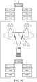
- FIG. 4 is a diagram of a virtual carrier aggregation and dual connectivity transmission scheme 400.
- the TRPs, 410, 450 collectively transmit data streams over respective groups of component carriers according to a virtual dual connectivity scheme.
- the TRP 410 transmits data streams to a UE (not shown) over component carriers using a primary cell 411 and virtual secondary cells 412, 413, 414 according to a virtual component carrier configuration
- the TRP 450 transmits data streams to the UE over component carriers using a virtual primary cell 461 and/or virtual secondary cells 462, 463, 464 according to a separate virtual component carrier scheme configuration.
- the TRP 410 transmits data streams over a physical component carrier using a primary cell 411, and over virtual component carriers using virtual secondary cells 412, 413, 414, and primary cell 411 and virtual secondary cells 412, 413, 414 belong to one master cell group (MCG).
- MCG master cell group
- the TRP 450 transmits data streams over a virtual component carrier using a virtual primary cell 461, and/or over virtual component carriers using virtual secondary cells 462, 463, 464, and virtual primary cell 461 and virtual secondary cells 462, 463, 464 belong to one virtual secondary cell group (virtual SCG).
- TAG time advance group
- the physical component carrier associated with the primary cell 411 and the virtual component carrier associated with the virtual secondary cell 412, 413, 414 belong to a physical component carrier group.
- the virtual component carrier associated with the virtual primary cell 461 and the virtual component carriers associated with the virtual secondary cell 462, 463, 464 belong to a separate virtual component carrier group.
- the term "physical component carrier group” refers to a group of component carriers that includes at least one physical component carrier
- the term “virtual component carrier group” refers to a group of component carriers that consists of virtual component carriers.
- the component carriers associated with the primary cell 411 and the virtual secondary cells 412, 413, 414 belong to an MCG 447 and the component carriers associated with the virtual primary cell 461 and the virtual secondary cells 462, 463, 464 belong to a virtual SCG 497.
- Component carriers associated with MCG 447 may be associated with a common MAC entity 445
- component carriers associated with virtual SCG 497 may be associated with a common MAC entity 495.
- the UE that receives the data streams according to the virtual dual connectivity scheme may be associated with different cell specific identifiers (e.g., different cell specific radio network temporary identifiers (C-RNTIs)) for different component carrier groups 447, 497.
- C-RNTIs cell specific radio network temporary identifiers
- one C-RNTI can be configured during a random access procedure and the other C-RNTI can be configured with RRC signaling.
- the UE may be assigned the same cell specific identifier (e.g., same C-RNTI) in the coverage areas, or RANs, associated with the respective component carrier groups 447, 497.
- frames communicated over physical and virtual component carriers align in the time domain.
- One or more channels carried in the frame have different durations such that a starting or ending symbol of a channel communicated over the physical component carrier is not aligned in the time domain with a corresponding channel communicated over the virtual component carrier.
- FIG. 5 is a diagram of frames 510, 520 communicated over a physical component carrier 591 and a virtual component carrier 592 (respectively).
- a PDCCH 512 in the frame 510 communicated over the physical component carrier 591 has a shorter duration than a PDCCH 522 in the frame 520 communicated over the virtual component carrier 592.
- an ending symbol location of the PDCCH 512 is not aligned in the time domain with an ending symbol location of the ending symbol location of the PDCCH 522.
- This may also affect the alignment of subsequent channels in the respective frames 510, 520.
- the starting and/or ending symbol locations of the PDSCH 514 in the frame 510 communicated over the physical component carrier 591 are not aligned in the time domain with the corresponding starting and/or ending symbol locations of the PDSCH 524 in the frame 520 communicated over the physical component carrier 592.
- a guard interval may be added to the frame 510 so that the end of the frame 510 aligns with the end of the frame 520.
- a starting or ending symbol location for at least one of a physical downlink control channel (PDCCH), a physical downlink shared channel (PDSCH) in the frame communicated over the physical component carrier can be detected by one common downlink control information without blind detection.
- a starting or ending symbol location for at least one of a physical downlink control channel (PDCCH), a physical downlink shared channel (PDSCH) in the frame communicated over the virtual component carrier can be configured by high layer RRC signaling.
- FIG. 6 is a diagram of frames 610, 620 communicated over a physical component carrier 691 and a virtual component carrier 692 (respectively).
- a PDCCH 612 in the frame 610 communicated over the physical component carrier 691 has a shorter duration than a PDCCH 622 in the frame 620 communicated over the virtual component carrier 692.
- each of the PDSCH 614, the PUCCH 616, and the PUSCH 618 in the frame 610 communicated over the physical component carrier 691 have different durations than a corresponding one of the PDSCH 624, the PUCCH 626, and the PUSCH 628 in the frame 620 communicated over the virtual component carrier 692.
- ending symbol locations of the PDCCH 612, the PDSCH 614, and the PUCCH 616 are not aligned in the time domain with ending symbol locations of the PDCCH 622, PDSCH 624, and PUCCH 626 (respectively), and starting symbol locations of the PDSCH 614, the PUCCH 616, and the PUSCH 618 are not aligned in the time domain with ending symbol locations of the PDSCH 624, PUCCH 626, and PUSCH 628 (respectively).
- a starting or ending symbol location for at least one of a physical downlink control channel (PDCCH), a physical downlink shared channel (PDSCH), a physical uplink shared channel (PUSCH) and a physical uplink control channel (PUCCH) in the frame communicated over the physical component carrier can be detected by one common downlink control information without blind detection.
- a starting or ending symbol location for at least one of a physical downlink control channel (PDCCH), a physical downlink shared channel (PDSCH), a physical uplink shared channel (PUSCH) and a physical uplink control channel (PUCCH) in the frame communicated over the virtual component carrier can be configured by high layer RRC signaling.
- each of the PDCCHs 612, 622, PDSCHs 614, 624, PUCCHs 616, 626, and PUSCHs 618, 628 have different durations
- PDCCHs communicated over physical and virtual component carriers may have the same duration
- the PDSCHs, PUCCHs, and/or PUSCHs may have different durations.
- one or more channels are excluded from the frame communicated over a virtual component carrier.
- a virtual component carrier may only carry a PDCCH and PDSCH, in which case the duration of the PDSCH may be extended to provide more downlink channel bandwidth.
- a starting or ending symbol location for at least one of a physical downlink control channel (PDCCH), a physical downlink shared channel (PDSCH), a physical uplink shared channel (PUSCH) and a physical uplink control channel (PUCCH) in the frame communicated over both the physical component carrier and the physical component carrier can be the same, and can be detected by one common downlink control information without blind detection if there is no specific configuration for a starting or ending symbol location for at least one of a physical downlink control channel (PDCCH), a physical downlink shared channel (PDSCH), a physical uplink shared channel (PUSCH) and a physical uplink control channel (PUCCH) in the frame communicated over the virtual component carrier.
- a physical downlink control channel a physical downlink shared channel (PDSCH), a physical uplink shared channel (PUSCH) and a physical uplink control channel (PUCCH) in the frame communicated over the virtual component carrier.
- a single PUCCH message may carry HARQ indication bits for codewords and/or code blocks and/or code block groups in frames communicated over both physical and virtual component carriers.
- FIG. 7 is a diagram of PUCCH message 780 carrying HARQ bits 782, 784, 786 that correspond to codewords communicated over physical and virtual component carriers.
- the HARQ bits 782, 784 indicate whether codewords 712, 714 (respectively) in a PDSCH 710 communicated over a physical component carrier 791 were successfully decoded by a UE.
- the HARQ bit 786 indicates whether a codewords 726 in a PDSCH 720 communicated over a virtual component carrier 792 were successfully decoded by the UE.
- FIGS. 8A-8F are diagrams of different virtual dual carrier high layer association configurations.
- FIG. 8A depicts a virtual dual carrier high layer association configuration in which different component carrier groups have separate MAC, RLC, and PDCP sublayers on the network-side and UE-side of the wireless links.
- FIG. 8B depicts a virtual dual carrier high layer association configuration in which different component carrier groups have a common physical sublayer on the UE-side of the wireless links, but have separate MAC, RLC, and PDCP sublayers on the network-side of the wireless links.
- FIG. 8C depicts a virtual dual carrier high layer association configuration in which different component carrier groups have a common PDPC sublayer on both the UE-side and network-side of the wireless links, but have separate MAC and RLC sublayers on the network-side of the wireless links.
- FIG. 8D depicts a virtual dual carrier high layer association configuration in which different component carrier groups have a common PDPC sublayer on both the UE-side and the network-side of the wireless links, and separate MAC and RLC sublayers on both the UE-side and the network-side of the wireless links.
- FIG. 8E depicts a virtual dual carrier high layer association configuration in which different component carrier groups have a common MAC sublayer on the UE-side of the wireless links, separate PDCP and RLC sublayers on the UE-side of the wireless links, and separate MAC, RLC, and PDCP sublayers on the network-side of the wireless links.
- FIG. 8F depicts a virtual dual carrier high layer association configuration in which different component carrier groups have a common MAC sublayer, a common PDCP sublayer, and separate RLC sublayers on the UE-side of the wireless links, and a common PDCP sublayer, as well as MAC, and RLC, sublayers, on the network-side of the wireless links.
- more than one HARQ processes can be simultaneously assigned by multiple assignments (e.g. PDCCH) for one unicast channel (e.g. PUSCH or PDSCH) within one time unit which can be one of slot, mini-slot and subframe.
- the maximum HARQ process number associated with multiple HARQ process assignments is different from the maximum HARQ process number associated with one HARQ process assignment.
- FIG. 9 depicts a component carrier associated with a maximum of 16 HARQ processes for a first UE (UE1), and another component carrier associated with a maximum of 8 HARQ processes for a second UE (UE2).
- UE1 is configured to receive two HARQ processes for unicast PDSCH or PUSCH via two assignments (PDCCH1 and PDCCH2) and UE2 is configured to receive one HARQ processes for unicast PDSCH or PUSCH via one assignment (PDCCH1).
- the maximum HARQ process number associated with one component carrier can be configured via explicit control signaling or derived from the UE- specific information via N x M, e.g., a number N of HARQ process assignments (e.g., received over one or multiple PDCCH channel) for unicast PDSCH or PUSCH within one time unit and initial maximum HARQ process number M.
- M can be predefined or configured with broadcasting channel for one component carrier
- N can be UE-specifically configured with high layer RRC signaling.
- one PUCCH resource will be used to transmit a combined HARQ feedback message, which may include HARQ bits associated with each codeword, code block, and/or code block group received over component carriers in a component carrier group or in a set of component carrier groups associated with a given UE.
- the total number of HARQ feedback may be determined by at least one of the number of component carrier numbers, the semi-static configured number of codewords and/or code blocks and/or code block groups.
- One HARQ bit is associated with one codeword, or one code block, or one code block group.
- each component carrier associated with each PDCCH and each TRP
- each component carrier will independently and dynamically schedule the CW number according to the traffic buffer.
- PDCCH1 schedules one CW and PDCCH2 schedules one CW, the at least 2 bit should be feedback to network side.
- PDCCH1 schedules one CW and PDCCH2 has no scheduling, then at least 1 bit should be feedback to network side.
- TRP1 physical carrier
- TRP2 virtual carrier
- the combined HARQ feedback bit number is based on the dynamic detection
- both TRP1 and TRP2 don't know the exact the dynamic feedback bit number and will fail the detection. So they should make a long-term or semi-static coordination for the feedback number for each carrier. Even during each scheduling, scheduling number of CW can be different, however feedback number should be definite. Then the high layer signaling should indicate the semi-static CW number and/or CB number and/or CBG number.
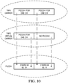
- FIG. 10 is a diagram of a mapping between HARQ bits in a PUCCH message and physical downlink control channels communicated over different component carriers.
- one PUCCH resource can be semi-statically configured to the UE.
- the combined HARQ feedback should be based over the specific ordering and mapping rules for all HARQ feedback bits.
- HARQ feedback bits corresponding to physical component carrier group or component carrier group associated with lower group indices precede HARQ feedback bits corresponding to virtual component carrier groups or component carrier groups associated with higher group indices, the physical component carrier group including at least one physical component carrier, and the virtual component carrier group consisting of virtual component carriers;
- HARQ feedback bits corresponding to one component carrier group HARQ feedback bits corresponding to component carrier associated with lower carrier indices precede HARQ feedback bits corresponding to component carriers associated with higher carrier indices in the given component carrier group; and/or HARQ feedback bits corresponding physical component carrier precede HARQ feedback bits corresponding to virtual component carriers in the given component carrier group.
- Table 1 includes rules for HARQ feedback bit concatenation in virtual dual connectivity schemes with indices for different component carrier groups, component carrier, codewords, and codeblocks.
- Table 1 HARQ feedback bit concatenation (more than one component carrier group) Component carrier group 1 Component carrier group 2 Component carrier 1 Component carrier 2 Component carrier 1 Component carrier 2 Codeword/ code block 1 Codeword/ code block 2 Codeword/ code block 1 Codeword/ code block 2 Codeword/ code block 1 Codeword/ code block 2 Codeword/ code block 1 Codeword/ code block 2 Codeword/ code block 1 Codeword/ code block 2
- HARQ feedback bits corresponding to one component carrier For HARQ feedback bits corresponding to one component carrier, HARQ feedback bits corresponding to codewords associated with lower codeword indices in a given component carrier precede HARQ feedback bits corresponding to codewords associated with higher codeword indices in the given component carrier.
- HARQ feedback bits corresponding to one codeword HARQ feedback bits corresponding to code blocks and/or code block groups associated with lower code block and/or code block group indices in a given codeword precede HARQ feedback bits corresponding to code blocks and/or code block groups associated with higher code block and/or code block group indices in the given codeword.
- Table 2 includes rules for HARQ feedback bit concatenation in virtual carrier aggregation with indices for different component carriers, codewords, and code blocks.
- Table 2 HARQ feedback bit concatenation (one component carrier group) Component carrier 1 Component carrier 2 Codeword/code block 1 Codeword/code block 2 Codeword/code block 1 Codeword/code block 2
- FIG. 11 illustrates a block diagram of an embodiment processing system 1100 for performing methods described herein, which may be installed in a host device.
- the processing system 1100 includes a processor 1104, a memory 1106, and interfaces 1110-1114, which may (or may not) be arranged as shown in FIG. 11 .
- the processor 1104 may be any component or collection of components adapted to perform computations and/or other processing related tasks
- the memory 1106 may be any component or collection of components adapted to store programming and/or instructions for execution by the processor 1104.
- the memory 1106 includes a non-transitory computer readable medium.
- the interfaces 1110, 1112, 1114 may be any component or collection of components that allow the processing system 1100 to communicate with other devices/components and/or a user.
- one or more of the interfaces 1110, 1112, 1114 may be adapted to communicate data, control, or management messages from the processor 1104 to applications installed on the host device and/or a remote device.
- one or more of the interfaces 1110, 1112, 1114 may be adapted to allow a user or user device (e.g., personal computer (PC), etc.) to interact/communicate with the processing system 1100.
- the processing system 1100 may include additional components not depicted in FIG. 11 , such as long term storage (e.g., non-volatile memory, etc.).
- the processing system 1100 is included in a network device that is accessing, or part otherwise of, a telecommunications network.
- the processing system 1100 is in a network-side device in a wireless or wireline telecommunications network, such as a base station, a relay station, a scheduler, a controller, a gateway, a router, an applications server, or any other device in the telecommunications network.
- the processing system 1100 is in a user-side device accessing a wireless or wireline telecommunications network, such as a mobile station, a user equipment (UE), a personal computer (PC), a tablet, a wearable communications device (e.g., a smartwatch, etc.), or any other device adapted to access a telecommunications network.
- a wireless or wireline telecommunications network such as a mobile station, a user equipment (UE), a personal computer (PC), a tablet, a wearable communications device (e.g., a smartwatch, etc.), or any other device adapted to access a telecommunications network.
- FIG. 12 illustrates a block diagram of a transceiver 1200 adapted to transmit and receive signaling over a telecommunications network.
- the transceiver 1200 may be installed in a host device. As shown, the transceiver 1200 comprises a network-side interface 1202, a coupler 1204, a transmitter 1206, a receiver 1208, a signal processor 1210, and a device-side interface 1212.
- the network-side interface 1202 may include any component or collection of components adapted to transmit or receive signaling over a wireless or wireline telecommunications network.
- the coupler 1204 may include any component or collection of components adapted to facilitate bi-directional communication over the network-side interface 1202.
- the transmitter 1206 may include any component or collection of components (e.g., up-converter, power amplifier, etc.) adapted to convert a baseband signal into a modulated carrier signal suitable for transmission over the network-side interface 1202.
- the receiver 1208 may include any component or collection of components (e.g., down-converter, low noise amplifier, etc.) adapted to convert a carrier signal received over the network-side interface 1202 into a baseband signal.
- the signal processor 1210 may include any component or collection of components adapted to convert a baseband signal into a data signal suitable for communication over the device-side interface(s) 1212, or vice-versa.
- the device-side interface(s) 1212 may include any component or collection of components adapted to communicate data-signals between the signal processor 1210 and components within the host device (e.g., the processing system 1100, local area network (LAN) ports
- the transceiver 1200 may transmit and receive signaling over any type of communications medium.
- the transceiver 1200 transmits and receives signaling over a wireless medium.
- the transceiver 1200 may be a wireless transceiver adapted to communicate in accordance with a wireless telecommunications protocol, such as a cellular protocol (e.g., long-term evolution (LTE), etc.), a wireless local area network (WLAN) protocol (e.g., Wi-Fi, etc.), or any other type of wireless protocol (e.g., Bluetooth, near field communication (NFC), etc.).
- the network-side interface 1202 comprises one or more antenna/radiating elements.
- the network-side interface 1202 may include a single antenna, multiple separate antennas, or a multi-antenna array configured for multi-layer communication, e.g., single input multiple output (SIMO), multiple input single output (MISO), multiple input multiple output (MIMO), etc.
- the transceiver 1200 transmits and receives signaling over a wireline medium, e.g., twisted-pair cable, coaxial cable, optical fiber, etc.
- Specific processing systems and/or transceivers may utilize all of the components shown, or only a subset of the components, and levels of integration may vary from device to device.
Description
- Embodiments of the present disclosure relate to the field of wireless network communications, and, in particular embodiments, to a system and method for virtual carrier and virtual connection aggregation.
- Next-generation wireless networks will need to provide higher throughput to support greater numbers of subscribers as well as applications requiring high data rates, such as video, high-definition images, and the like. Various techniques are available to increase the overall throughput provided to mobile devices in a wireless network. For example, carrier aggregation and dual connectivity techniques transmit data to a user equipment (UE) over multiple component carriers at the same time, thereby increasing the bandwidth available to the UE. In addition, one component carrier is also associated with one cell or serving cell with specific cell ID and carrier frequency in LTE. Generally, one component carrier with specific cell ID and specific carrier frequency can also be regarded as one physical component carrier. Moreover, each physical component carrier can be associated with one primary cell (PCell) or secondary cell (SCell).
- The difference between carrier aggregation and dual connectivity lies primarily in the degree to which data transmissions over the component carriers are synchronized and/or coordinated. Carrier aggregation is typically used when a single transmit point is transmitting data over the aggregated carriers, or otherwise when multiple transmit points connected by a low-latency backhaul link (e.g., a near ideal backhaul link) are transmitting data streams over the aggregated carriers belonging to one carrier group (e.g., master cell group, MCG). In contrast, dual connectivity is typically used when multiple transmit points that are connected by a higher latency backhaul link (e.g., a non-ideal backhaul link) are transmitting data streams over the aggregated carriers belonging to two different carrier groups (e.g., both master cell group, MCG and secondary cell group, SCG).
- Further, prior art document Mikio, Iwamura et. al., "Carrier aggregation framework in 3GPP LTE-advanced [WiMAX/LTE Update]", IEEE Communications magazine, 1. August 2010 refers to a carrier aggregation framework in 3GPP LTE-advanced.
- Example aspects of the present disclosure which provide a system and method for virtual carrier and virtual connection aggregation. This problem is solved by the subject matter of the independent claims. Further implementation forms are provided in the dependent claims.
- For a more complete understanding of the present invention, and the advantages thereof, reference is now made to the following description taken in conjunction with the accompanying drawings, in which:
-
FIG. 1 is a diagram of a wireless network; -
FIG. 2 is a diagram of a virtual carrier aggregation transmission scheme; -
FIG. 3 is a diagram of a virtual dual connectivity transmission scheme; -
FIG. 4 is a diagram of a virtual carrier aggregation and dual connectivity transmission scheme; -
FIG. 5 is a diagram of frames communicated over physical and virtual component carriers according to a virtual carrier aggregation or dual connectivity transmission scheme; -
FIG. 6 is another diagram of frames communicated over physical and virtual component carriers according to a virtual carrier aggregation or dual connectivity transmission scheme; -
FIG. 7 is a diagram of a PUCCH message carrying HARQ bits corresponding to codewords in frames communicated over physical and virtual component carriers according to a virtual carrier aggregation or dual connectivity transmission scheme; -
FIGS. 8A-8E are diagrams of embodiment virtual dual carrier channel configurations; -
FIG. 9 is a diagram of component carrier associated with different maximum numbers of HARQ processes for different UEs; -
FIG. 10 is a diagram of a mapping between HARQ bits in a PUCCH message and physical downlink control channels communicated over different component carriers; -
FIG. 11 is a block diagram of an embodiment processing system for performing methods described herein; and -
FIG. 12 is a block diagram of a transceiver adapted to transmit and receive signaling over a telecommunications network according to example embodiments described herein. - Corresponding numerals and symbols in the different figures generally refer to corresponding parts unless otherwise indicated. The figures are drawn to clearly illustrate the relevant aspects of the embodiments and are not necessarily drawn to scale.
- The making and using of specific embodiments are discussed in detail below. It should be appreciated, however, that the claimed concepts that can be embodied in a wide variety of specific contexts. The specific embodiments discussed are merely illustrative of specific ways to make and use the invention, and do not limit the scope of the invention. The terms "component carrier," "carrier," "aggregated carrier," and "aggregated component carrier," and "carrier group" are used interchangeably throughout this disclosure. A component carrier may be associated with a serving cell; A physical component carrier may be associated with a primary serving cell (PCell) with one cell ID, and a virtual component carrier may be associated with a virtual secondary cell (virtual SCell). A component carrier group may be associated with a serving cell group. For example, a physical component carrier group may be associated with a MSG and a virtual component carrier group may be associated with a virtual SCG.
- As mentioned above, carrier aggregation and dual connectivity leverage multiple component carriers to increase the effective bandwidth available to a given UE. Embodiments of this disclosure extend the concept of carrier aggregation and dual connectivity by using a physical component carrier and one or more virtual component carriers from one physical component carrier group and/or one virtual component carrier group, which have the same carrier frequency and carrier bandwidth as the physical component carrier, to transmit data streams to a user equipment. Data streams communicated over the physical component carrier and the virtual component carrier(s) may be orthogonal in the time domain or code domain. Alternatively, data streams communicated over the physical component carrier and the virtual component carrier(s) may be non-orthogonal, in which case the UE may need to decode the respective data streams using non-orthogonal signal processing techniques.
- In some embodiments, a physical component carrier and a virtual component carrier in the same component carrier group may be used to transmit data streams to a UE using a virtual carrier aggregation scheme. In such embodiments, the physical component carrier and the virtual component carrier may be assigned different carrier indices, while being associated with a common media access control (MAC) sublayer, a common radio link control (RLC) sublayer, and/or a common packet data convergence protocol (PDCP) sublayer. Assignments of carrier indices to physical/virtual component carriers may be a priori information of the UE, or otherwise communicated via higher layer signaling (e.g., RRC signaling, etc.). For example, the carrier index to the physical carrier can be zero and the carrier indices to the virtual carrier can be configured with a non-zero integer by the higher layer signaling. In other embodiments, a physical component carrier and a virtual component carrier, that are in different component carrier groups, may be used to transmit data streams to a UE using a virtual dual connectivity scheme. For example, a physical component carrier can be associated with a physical component carrier group and a virtual component carrier can be associated with a virtual component carrier group. In such embodiments, the physical component carrier and the virtual component carrier may be associated with different MAC sublayers, different RLC sublayers, and/or different PDCP sublayers.
- Physical and virtual component carriers that are used to transmit data streams to a UE in accordance with embodiment virtual carrier aggregation and/or dual connectivity schemes may be associated with the same timing advance group (TAG), as well as have the same cyclic prefix (CP) durations, sub-carrier spacings, bandwidth partitions, and/or physical cell identifier (PCI). In some embodiments, frames communicated over physical and virtual component carriers that are being used for virtual carrier aggregation and/or dual connectivity may align in the time domain. In such embodiments, subframes in a frame communicated over the physical component carrier may be aligned in the time domain with subframes in a frame communicated over the virtual component carrier. The respective frames may carry the same number of subframes. Pairs of subframes, transmitted over the respective physical and virtual component carriers, that align in the time domain may be associated with the same subframe index.
- Although frames communicated over respective physical and virtual component carriers may align in the time domain, individual channels within those frames may have different durations and/or different starting and ending symbol locations. By way of example, a physical downlink control channel (PDCCH) in a frame communicated over a physical component carrier may have a different duration than a PDCCH communicated over a corresponding virtual component carrier. When a channel communicated over a physical component carrier has a different duration than a corresponding channel communicated over a virtual component carrier, the last symbol (or ending symbol location) of the channel communicated over the physical component carrier may not align in the time domain with the last symbol (or ending symbol location) of the corresponding channel communicated over the physical component carrier. As an extension, subsequent channels in the respective physical and virtual component carriers may also have misaligned channel boundaries. For instance, if an ending symbol of a PDCCH communicated over a physical component carrier is misaligned with an ending symbol location of a PDCCH communicated over a corresponding virtual component carrier, then a starting and/or ending symbol location of a subsequent physical downlink shared channel (PDSCH) communicated over the physical component carrier may likewise be misaligned with a starting and/or ending symbol location of a PDSCH communicated over the corresponding virtual component carrier. These and other aspects are described in greater detail below.
- In some embodiments, frames communicated over the physical component carrier and the frame communicated over the virtual component carrier share a common downlink synchronization channel (SCH). In such embodiments, one UE only receive the DL SCH associated with the physical component carrier. In some embodiments frame communicated over the physical component carrier and the frame communicated over the virtual component carrier share a common physical broadcast channel (PBCH). In such embodiments, a UE only receives the DL PBCH associated with the physical component carrier. In some embodiments, the frame communicated over the physical component carrier and the frame communicated over the virtual component carrier share a common search space in a physical downlink control channel (PDCCH). In such embodiments, a UE only monitors the common search space associated with the physical component carrier. In some embodiments, the frame communicated over the physical component carrier and the frame communicated over the virtual component carrier share a common downlink control information (e.g., for the time unit structure) without blind detection. In such embodiments, a UE only monitors the common downlink control information associated with the physical component carrier wherein time unit can be slot and/or mini-slot and/or subframe.
-
FIG. 1 illustrates anetwork 100 for communicating data. Thenetwork 100 comprises a transmit/receive point (TRP) 110 having a coverage area 101, a plurality ofmobile devices 103, and abackhaul network 104. As shown, theTRP 110 establishes uplink (dashed line) and/or downlink (dotted line) connections with the user equipments (UEs) 101, which serve to carry data from the UEs to theTRP 110 and vice-versa. Data carried over the uplink/downlink connections may include data communicated between theUEs 103, as well as data communicated to/from a remote-end (not shown) by way of thebackhaul network 104. As used herein, the term "TRP" refers to any component (or collection of components) configured to provide wireless access to a network, such as a base station, an evolved NodeB (eNodeB or eNB) or a gNB, a macro-cell, a femtocell, a Wi-Fi access point (AP), or other wirelessly enabled devices. TRPs may provide wireless access in accordance with one or more wireless communication protocols, e.g., long term evolution (LTE), LTE advanced (LTE-A), High Speed Packet Access (HSPA), Wi-Fi 802.11a/b/g/n/ac, etc. As used herein, the term "UE" refers to any component (or collection of components) capable of establishing a wireless connection with a base station, such as a mobile device, a mobile station (STA), and other wirelessly enabled devices. In some embodiments, thenetwork 100 may comprise various other wireless devices, such as relays, low power nodes, etc. - Aspects of this disclosure provide embodiment virtual carrier aggregation techniques.
FIG. 2 is a diagram of a virtual carrieraggregation transmission scheme 200. As shown, aTRP 210 transmits data streams to aUE 203 over aphysical component carrier 291 and avirtual component carrier 292 that belong to the same component carrier group. In this example, theTRP 210 includes a primary cell (PCell) 211 that transmits a data stream over thephysical component carrier 291 and a virtual secondary cell (Virtual SCell) 212 that transmits a data stream over thevirtual component carrier 292. A Hybrid Automatic Repeat reQuest (HARQ)entity 221 determines whether codewords (CW) and/or code blocks (CB) and/or code block groups (CBG) transmitted over thephysical component carrier 291 were successfully decoded by theUE 203, and theHARQ entity 222 determines whether codewords and/or code blocks and/or code block groups transmitted over thevirtual component carrier 292 were successfully decoded by theUE 203. At least one codeword transmitted over thephysical component carrier 291 may be associated with a corresponding one of the HARQ processes 231, and at least one codeword transmitted over thevirtual component carrier 292 may be associated with a corresponding one of the HARQ processes 232. - Aspects of this disclosure also provide embodiment virtual dual connectivity techniques.
FIG. 3 is a diagram of a virtual dualconnectivity transmission scheme 300. As shown, aTRP 310 transmits a data stream to aUE 303 over aphysical component carrier 391, and aTRP 310 transmits a data stream to theUE 303 over a virtual component carrier 392, which belongs to a different component carrier group than thephysical component carrier 391. For example, a physical component carrier may belong to a physical component carrier group and a virtual component carrier may belong to a virtual component carrier group. In this example, theTRP 310 includes a primary cell (PCell) 311 that transmits data over thephysical component carrier 391, and aHARQ entity 321 determines whether codewords and/or code blocks and/or code block groups transmitted over the over thephysical component carrier 391 were successfully decoded by theUE 303. Similarly, theTRP 350 includes a virtual secondary cell (virtual SCell) 352 that transmits data over the virtual component carrier 392, and aHARQ entity 362 that determines whether codewords and/or code blocks and/or code block groups transmitted over the over the virtual component carrier 392 were successfully decoded by theUE 303. At least one codeword transmitted over thephysical component carrier 391 may be associated with a corresponding one of the HARQ processes 331, and at least one codeword transmitted over the physical component carrier 392 may be associated with a corresponding one of the HARQ processes 372. - The
TRP 310 and theTRP 350 may be connected by a backhaul connection that is incapable of providing sufficient ideal coordination for conventional, or virtual, carrier aggregation. For example, a latency associated with signaling communicated over the backhaul may be such that the backhaul is not capable of supporting a common MAC, RLC, and/or PDCP sublayer for data transmissions by therespective TRPs - In some instances, virtual carrier aggregation and virtual dual connectivity schemes may be combined to provide additional simultaneous data channel assignment (e.g.,HARQ process assignment) to a UE.
FIG. 4 is a diagram of a virtual carrier aggregation and dualconnectivity transmission scheme 400. Collectively speaking, the TRPs, 410, 450 collectively transmit data streams over respective groups of component carriers according to a virtual dual connectivity scheme. Individually speaking, theTRP 410 transmits data streams to a UE (not shown) over component carriers using aprimary cell 411 and virtualsecondary cells TRP 450 transmits data streams to the UE over component carriers using a virtualprimary cell 461 and/or virtualsecondary cells - In particular, the
TRP 410 transmits data streams over a physical component carrier using aprimary cell 411, and over virtual component carriers using virtualsecondary cells primary cell 411 and virtualsecondary cells TRP 450 transmits data streams over a virtual component carrier using a virtualprimary cell 461, and/or over virtual component carriers using virtualsecondary cells primary cell 461 and virtualsecondary cells -
Primary cell 411, virtualsecondary cells primary cell 461, and virtualsecondary cells - In one embodiment, the physical component carrier associated with the
primary cell 411 and the virtual component carrier associated with the virtualsecondary cell primary cell 461 and the virtual component carriers associated with the virtualsecondary cell - In this example, the component carriers associated with the
primary cell 411 and the virtualsecondary cells MCG 447 and the component carriers associated with the virtualprimary cell 461 and the virtualsecondary cells virtual SCG 497. Component carriers associated withMCG 447 may be associated with acommon MAC entity 445, and component carriers associated withvirtual SCG 497 may be associated with acommon MAC entity 495. In some embodiments, the UE that receives the data streams according to the virtual dual connectivity scheme may be associated with different cell specific identifiers (e.g., different cell specific radio network temporary identifiers (C-RNTIs)) for differentcomponent carrier groups component carrier groups - In some embodiments, frames communicated over physical and virtual component carriers align in the time domain. One or more channels carried in the frame have different durations such that a starting or ending symbol of a channel communicated over the physical component carrier is not aligned in the time domain with a corresponding channel communicated over the virtual component carrier.
FIG. 5 is a diagram offrames physical component carrier 591 and a virtual component carrier 592 (respectively). In this example, aPDCCH 512 in theframe 510 communicated over thephysical component carrier 591 has a shorter duration than aPDCCH 522 in theframe 520 communicated over thevirtual component carrier 592. As a result, an ending symbol location of thePDCCH 512 is not aligned in the time domain with an ending symbol location of the ending symbol location of thePDCCH 522. This may also affect the alignment of subsequent channels in therespective frames PDSCH 514 in theframe 510 communicated over thephysical component carrier 591 are not aligned in the time domain with the corresponding starting and/or ending symbol locations of thePDSCH 524 in theframe 520 communicated over thephysical component carrier 592. A guard interval may be added to theframe 510 so that the end of theframe 510 aligns with the end of theframe 520. In such embodiments, a starting or ending symbol location for at least one of a physical downlink control channel (PDCCH), a physical downlink shared channel (PDSCH) in the frame communicated over the physical component carrier can be detected by one common downlink control information without blind detection. A starting or ending symbol location for at least one of a physical downlink control channel (PDCCH), a physical downlink shared channel (PDSCH) in the frame communicated over the virtual component carrier can be configured by high layer RRC signaling. -
FIG. 6 is a diagram offrames 610, 620 communicated over aphysical component carrier 691 and a virtual component carrier 692 (respectively). LikeFIG. 5 , aPDCCH 612 in the frame 610 communicated over thephysical component carrier 691 has a shorter duration than aPDCCH 622 in theframe 620 communicated over thevirtual component carrier 692. Additionally, inFIG. 6 , each of thePDSCH 614, thePUCCH 616, and thePUSCH 618 in the frame 610 communicated over thephysical component carrier 691 have different durations than a corresponding one of thePDSCH 624, thePUCCH 626, and thePUSCH 628 in theframe 620 communicated over thevirtual component carrier 692. Additionally, as a result of the different channel durations, ending symbol locations of thePDCCH 612, thePDSCH 614, and thePUCCH 616 are not aligned in the time domain with ending symbol locations of thePDCCH 622,PDSCH 624, and PUCCH 626 (respectively), and starting symbol locations of thePDSCH 614, thePUCCH 616, and thePUSCH 618 are not aligned in the time domain with ending symbol locations of thePDSCH 624,PUCCH 626, and PUSCH 628 (respectively). In such embodiments, a starting or ending symbol location for at least one of a physical downlink control channel (PDCCH), a physical downlink shared channel (PDSCH), a physical uplink shared channel (PUSCH) and a physical uplink control channel (PUCCH) in the frame communicated over the physical component carrier can be detected by one common downlink control information without blind detection. A starting or ending symbol location for at least one of a physical downlink control channel (PDCCH), a physical downlink shared channel (PDSCH), a physical uplink shared channel (PUSCH) and a physical uplink control channel (PUCCH) in the frame communicated over the virtual component carrier can be configured by high layer RRC signaling. AlthoughFIG. 6 depicts an example in which each of thePDCCHs PDSCHs PUCCHs PUSCHs - In such embodiments, a starting or ending symbol location for at least one of a physical downlink control channel (PDCCH), a physical downlink shared channel (PDSCH), a physical uplink shared channel (PUSCH) and a physical uplink control channel (PUCCH) in the frame communicated over both the physical component carrier and the physical component carrier can be the same, and can be detected by one common downlink control information without blind detection if there is no specific configuration for a starting or ending symbol location for at least one of a physical downlink control channel (PDCCH), a physical downlink shared channel (PDSCH), a physical uplink shared channel (PUSCH) and a physical uplink control channel (PUCCH) in the frame communicated over the virtual component carrier.
- In some embodiments, a single PUCCH message may carry HARQ indication bits for codewords and/or code blocks and/or code block groups in frames communicated over both physical and virtual component carriers.
FIG. 7 is a diagram ofPUCCH message 780 carryingHARQ bits HARQ bits codewords 712, 714 (respectively) in aPDSCH 710 communicated over aphysical component carrier 791 were successfully decoded by a UE. TheHARQ bit 786 indicates whether acodewords 726 in aPDSCH 720 communicated over avirtual component carrier 792 were successfully decoded by the UE. - In embodiment virtual dual connectivity schemes, virtual and physical component carriers may have different high layer association configurations.
FIGS. 8A-8F are diagrams of different virtual dual carrier high layer association configurations. In particular,FIG. 8A depicts a virtual dual carrier high layer association configuration in which different component carrier groups have separate MAC, RLC, and PDCP sublayers on the network-side and UE-side of the wireless links. -
FIG. 8B depicts a virtual dual carrier high layer association configuration in which different component carrier groups have a common physical sublayer on the UE-side of the wireless links, but have separate MAC, RLC, and PDCP sublayers on the network-side of the wireless links. -
FIG. 8C depicts a virtual dual carrier high layer association configuration in which different component carrier groups have a common PDPC sublayer on both the UE-side and network-side of the wireless links, but have separate MAC and RLC sublayers on the network-side of the wireless links. -
FIG. 8D depicts a virtual dual carrier high layer association configuration in which different component carrier groups have a common PDPC sublayer on both the UE-side and the network-side of the wireless links, and separate MAC and RLC sublayers on both the UE-side and the network-side of the wireless links. -
FIG. 8E depicts a virtual dual carrier high layer association configuration in which different component carrier groups have a common MAC sublayer on the UE-side of the wireless links, separate PDCP and RLC sublayers on the UE-side of the wireless links, and separate MAC, RLC, and PDCP sublayers on the network-side of the wireless links. -
FIG. 8F depicts a virtual dual carrier high layer association configuration in which different component carrier groups have a common MAC sublayer, a common PDCP sublayer, and separate RLC sublayers on the UE-side of the wireless links, and a common PDCP sublayer, as well as MAC, and RLC, sublayers, on the network-side of the wireless links. - In some embodiments, for one physical component carrier or one virtual component carrier, more than one HARQ processes can be simultaneously assigned by multiple assignments (e.g. PDCCH) for one unicast channel (e.g. PUSCH or PDSCH) within one time unit which can be one of slot, mini-slot and subframe. In such embodiments, for one physical component carrier or one virtual component carrier, the maximum HARQ process number associated with multiple HARQ process assignments is different from the maximum HARQ process number associated with one HARQ process assignment.
FIG. 9 depicts a component carrier associated with a maximum of 16 HARQ processes for a first UE (UE1), and another component carrier associated with a maximum of 8 HARQ processes for a second UE (UE2). In this example, UE1 is configured to receive two HARQ processes for unicast PDSCH or PUSCH via two assignments (PDCCH1 and PDCCH2) and UE2 is configured to receive one HARQ processes for unicast PDSCH or PUSCH via one assignment (PDCCH1). For each UE, the maximum HARQ process number associated with one component carrier can be configured via explicit control signaling or derived from the UE- specific information via N x M, e.g., a number N of HARQ process assignments (e.g., received over one or multiple PDCCH channel) for unicast PDSCH or PUSCH within one time unit and initial maximum HARQ process number M. M can be predefined or configured with broadcasting channel for one component carrier, and N can be UE-specifically configured with high layer RRC signaling. - In some embodiments, one PUCCH resource will be used to transmit a combined HARQ feedback message, which may include HARQ bits associated with each codeword, code block, and/or code block group received over component carriers in a component carrier group or in a set of component carrier groups associated with a given UE. In such embodiments, the total number of HARQ feedback may be determined by at least one of the number of component carrier numbers, the semi-static configured number of codewords and/or code blocks and/or code block groups. One HARQ bit is associated with one codeword, or one code block, or one code block group. For the example of HARQ feedback, each component carrier (associated with each PDCCH and each TRP) will independently and dynamically schedule the CW number according to the traffic buffer. For the first time, PDCCH1 schedules one CW and PDCCH2 schedules one CW, the at least 2 bit should be feedback to network side. For the second time, PDCCH1 schedules one CW and PDCCH2 has no scheduling, then at least 1 bit should be feedback to network side.
- However, this combined HARQ feedback should be known to TRPs without ideal coordination. This means TRP1 (physical carrier) doesn't know how many CW will be scheduled by TRP2 (virtual carrier). If the combined HARQ feedback bit number is based on the dynamic detection, both TRP1 and TRP2 don't know the exact the dynamic feedback bit number and will fail the detection. So they should make a long-term or semi-static coordination for the feedback number for each carrier. Even during each scheduling, scheduling number of CW can be different, however feedback number should be definite. Then the high layer signaling should indicate the semi-static CW number and/or CB number and/or CBG number. Then the total feedback number can be determined based on the component number and associated semi-static CW/CB/CBG number. Note that, the dynamic scheduling of CW/CB/CBG will not be larger than the semi-static number.
FIG. 10 is a diagram of a mapping between HARQ bits in a PUCCH message and physical downlink control channels communicated over different component carriers. - In some embodiments, for transmitting one combined HARQ feedback associated with both physical component carrier and virtual physical component carrier which can be from same and different component carrier group, one PUCCH resource can be semi-statically configured to the UE.
- In some embodiments, the combined HARQ feedback should be based over the specific ordering and mapping rules for all HARQ feedback bits.
- For all HARQ feedback bits corresponding to different component carrier groups, HARQ feedback bits corresponding to physical component carrier group or component carrier group associated with lower group indices precede HARQ feedback bits corresponding to virtual component carrier groups or component carrier groups associated with higher group indices, the physical component carrier group including at least one physical component carrier, and the virtual component carrier group consisting of virtual component carriers; For HARQ feedback bits corresponding to one component carrier group, HARQ feedback bits corresponding to component carrier associated with lower carrier indices precede HARQ feedback bits corresponding to component carriers associated with higher carrier indices in the given component carrier group; and/or HARQ feedback bits corresponding physical component carrier precede HARQ feedback bits corresponding to virtual component carriers in the given component carrier group. Table 1 includes rules for HARQ feedback bit concatenation in virtual dual connectivity schemes with indices for different component carrier groups, component carrier, codewords, and codeblocks.
Table 1 HARQ feedback bit concatenation (more than one component carrier group) Component carrier group 1Component carrier group 2Component carrier 1Component carrier 2Component carrier 1Component carrier 2Codeword/ code block 1Codeword/ code block 2Codeword/ code block 1Codeword/ code block 2Codeword/ code block 1Codeword/ code block 2Codeword/ code block 1Codeword/ code block 2 - For HARQ feedback bits corresponding to one component carrier, HARQ feedback bits corresponding to codewords associated with lower codeword indices in a given component carrier precede HARQ feedback bits corresponding to codewords associated with higher codeword indices in the given component carrier. For HARQ feedback bits corresponding to one codeword, HARQ feedback bits corresponding to code blocks and/or code block groups associated with lower code block and/or code block group indices in a given codeword precede HARQ feedback bits corresponding to code blocks and/or code block groups associated with higher code block and/or code block group indices in the given codeword. Table 2 includes rules for HARQ feedback bit concatenation in virtual carrier aggregation with indices for different component carriers, codewords, and code blocks.
Table 2 HARQ feedback bit concatenation (one component carrier group) Component carrier 1Component carrier 2Codeword/ code block 1Codeword/ code block 2Codeword/ code block 1Codeword/ code block 2 -
FIG. 11 illustrates a block diagram of anembodiment processing system 1100 for performing methods described herein, which may be installed in a host device. As shown, theprocessing system 1100 includes aprocessor 1104, amemory 1106, and interfaces 1110-1114, which may (or may not) be arranged as shown inFIG. 11 . Theprocessor 1104 may be any component or collection of components adapted to perform computations and/or other processing related tasks, and thememory 1106 may be any component or collection of components adapted to store programming and/or instructions for execution by theprocessor 1104. In an embodiment, thememory 1106 includes a non-transitory computer readable medium. Theinterfaces processing system 1100 to communicate with other devices/components and/or a user. For example, one or more of theinterfaces processor 1104 to applications installed on the host device and/or a remote device. As another example, one or more of theinterfaces processing system 1100. Theprocessing system 1100 may include additional components not depicted inFIG. 11 , such as long term storage (e.g., non-volatile memory, etc.). - In some embodiments, the
processing system 1100 is included in a network device that is accessing, or part otherwise of, a telecommunications network. In one example, theprocessing system 1100 is in a network-side device in a wireless or wireline telecommunications network, such as a base station, a relay station, a scheduler, a controller, a gateway, a router, an applications server, or any other device in the telecommunications network. In other embodiments, theprocessing system 1100 is in a user-side device accessing a wireless or wireline telecommunications network, such as a mobile station, a user equipment (UE), a personal computer (PC), a tablet, a wearable communications device (e.g., a smartwatch, etc.), or any other device adapted to access a telecommunications network. - In some embodiments, one or more of the
interfaces processing system 1100 to a transceiver adapted to transmit and receive signaling over the telecommunications network.FIG. 12 illustrates a block diagram of atransceiver 1200 adapted to transmit and receive signaling over a telecommunications network. Thetransceiver 1200 may be installed in a host device. As shown, thetransceiver 1200 comprises a network-side interface 1202, acoupler 1204, atransmitter 1206, areceiver 1208, asignal processor 1210, and a device-side interface 1212. The network-side interface 1202 may include any component or collection of components adapted to transmit or receive signaling over a wireless or wireline telecommunications network. Thecoupler 1204 may include any component or collection of components adapted to facilitate bi-directional communication over the network-side interface 1202. Thetransmitter 1206 may include any component or collection of components (e.g., up-converter, power amplifier, etc.) adapted to convert a baseband signal into a modulated carrier signal suitable for transmission over the network-side interface 1202. Thereceiver 1208 may include any component or collection of components (e.g., down-converter, low noise amplifier, etc.) adapted to convert a carrier signal received over the network-side interface 1202 into a baseband signal. Thesignal processor 1210 may include any component or collection of components adapted to convert a baseband signal into a data signal suitable for communication over the device-side interface(s) 1212, or vice-versa. The device-side interface(s) 1212 may include any component or collection of components adapted to communicate data-signals between thesignal processor 1210 and components within the host device (e.g., theprocessing system 1100, local area network (LAN) ports, etc.). - The
transceiver 1200 may transmit and receive signaling over any type of communications medium. In some embodiments, thetransceiver 1200 transmits and receives signaling over a wireless medium. For example, thetransceiver 1200 may be a wireless transceiver adapted to communicate in accordance with a wireless telecommunications protocol, such as a cellular protocol (e.g., long-term evolution (LTE), etc.), a wireless local area network (WLAN) protocol (e.g., Wi-Fi, etc.), or any other type of wireless protocol (e.g., Bluetooth, near field communication (NFC), etc.). In such embodiments, the network-side interface 1202 comprises one or more antenna/radiating elements. For example, the network-side interface 1202 may include a single antenna, multiple separate antennas, or a multi-antenna array configured for multi-layer communication, e.g., single input multiple output (SIMO), multiple input single output (MISO), multiple input multiple output (MIMO), etc. In other embodiments, thetransceiver 1200 transmits and receives signaling over a wireline medium, e.g., twisted-pair cable, coaxial cable, optical fiber, etc. Specific processing systems and/or transceivers may utilize all of the components shown, or only a subset of the components, and levels of integration may vary from device to device.
Claims (14)
- A method for receiving data performed by a user equipment, UE (203), the method comprising:• receiving a first data stream over a physical component carrier (291) from a transmission point, TP, and a second data stream over a virtual component carrier (292) from the TP, the physical component carrier and the virtual component carrier having a same carrier frequency and a same carrier bandwidth, the physical component carrier and the virtual component carrier belonging to a same component carrier group and being assigned different carrier indices;• wherein a frame, in the first data stream, communicated over the physical component carrier is aligned in the time domain with a frame, in the second data stream, communicated over the virtual component carrier, and the method further comprises:∘ decoding a downlink control information, DCI, message carried by the frame communicated over the physical component carrier, the DCI message indicating a starting or ending symbol location for at least one of a physical downlink control channel, PDCCH, a physical downlink shared channel, PDSCH, a physical uplink control channel, PUCCH, and a physical uplink shared channel, PUSCH, in the frame communicated over the physical component carrier; and∘ determining that the starting or ending symbol location indicated by the DCI message carried by the frame communicated over the physical component carrier also indicates a starting or ending symbol location for at least one of a PDCCH, a PDSCH, a PUCCH, and a PUSCH in the frame communicated over the virtual component carrier when the starting or ending symbol location for a corresponding one of the PDCCH, the PDSCH, the PUCCH, and the PUSCH in the frame communicated over the virtual component carrier has not been configured via higher layer signaling.
- The method of claim 1, wherein the physical component carrier and the virtual component carrier are associated with a common media access control, MAC, sublayer, a common radio link control, RLC, sublayer, and a common packet data convergence protocol, PDCP, sublayer.
- The method of any of claims 1 to 2, wherein the physical component carrier and the virtual component carrier are associated with the same physical cell identifier, PCI; or the physical component carrier and the virtual component carrier are associated with the same timing advance group, TAG; or the physical component carrier and the virtual component carrier are associated with the same cyclic prefix, CP, duration; or the physical component carrier and the virtual component carrier are associated with the same sub-carrier spacing; or the physical component carrier and the virtual component carrier are associated with the same bandwidth partition.
- The method of any of claims 1 to 3, wherein subframes in the frame communicated over the physical component carrier are aligned in the time domain with subframes in the frame communicated over the virtual component carrier, the frame communicated over the physical component carrier carrying the same number of subframes as the frame communicated over the virtual component carrier, wherein pairs of subframes, transmitted over the respective physical and virtual component carriers, that align in the time domain are associated with the same subframe index.
- The method of any of claims 1 to 4, wherein at least one of the PDCCH, the PDSCH, the PUCCH, and the PUSCH, in the frame communicated over the physical component carrier has a different duration than corresponding one of the PDCCH, the PDSCH, the PUCCH, and the PUSCH in the frame communicated over the virtual component carrier.
- The method of any of claims 1 to 5, wherein the frame communicated over the physical component carrier and the frame communicated over the virtual component carrier share a common downlink synchronization channel, SCH; or the frame communicated over the physical component carrier and the frame communicated over the virtual component carrier share a common physical broadcast channel, PBCH; or the frame communicated over the physical component carrier and the frame communicated over the virtual component carrier share a common search space in a physical downlink control channel, PDCCH.
- The method of any of claims 1 to 6, wherein the frame communicated over the physical component carrier and the frame communicated over the virtual component carrier share a downlink control information, DCI, message without blind detection.
- The method of any of claims 1 to 7, wherein the UE does not receive an uplink grant for resources in the PUSCH of the frame communicated over the virtual component carrier.
- The method of any of claims 1 to 8, wherein the physical component carrier has an associated first maximum number of HARQ processes, independently of a number of active HARQ processes in the virtual component carrier, and the virtual component carrier has an associated second maximum number of HARQ processes, independently of a number of active HARQ processes in the physical component carrier.
- The method of any of claims 1 to 9, further comprising:
transmitting a single physical uplink control channel, PUCCH, message, the PUCCH message including at least a first HARQ feedback bit indicating whether a codeword or code block carried by the first data stream was successfully decoded by the UE, and at least a second HARQ feedback bit indicating whether a codeword and/or code block carried by the second data stream was successfully decoded by the UE. - The method of claim 10, wherein the total number of HARQ feedback bits in the PUCCH message is based on a combined number of codewords and/or code blocks carried by data streams received over component carriers in a group of component carriers that includes the physical component carrier and the virtual component carrier.
- The method of any of claims 1 to 11, further comprising:descrambling a first message carried by the first data stream according to a scrambling identity associated with a physical cell identifier, PCI, assigned to the physical component carrier; anddescrambling a second message carried by the second data stream using either the scrambling identity associated with the PCI or a scrambling identity configured through higher layer signaling.
- The method of any of claims 1 to 12, wherein the first data stream is orthogonal to the second data stream in the code domain.
- A user equipment, UE, configured to perform the method of any of claims 1 to 13.
Applications Claiming Priority (2)
| Application Number | Priority Date | Filing Date | Title |
|---|---|---|---|
| US201762506462P | 2017-05-15 | 2017-05-15 | |
| PCT/CN2018/086714 WO2018210205A1 (en) | 2017-05-15 | 2018-05-14 | Virtual carrier and virtual connection aggregation |
Publications (3)
| Publication Number | Publication Date |
|---|---|
| EP3628137A1 EP3628137A1 (en) | 2020-04-01 |
| EP3628137A4 EP3628137A4 (en) | 2020-05-06 |
| EP3628137B1 true EP3628137B1 (en) | 2022-01-26 |
Family
ID=64273397
Family Applications (1)
| Application Number | Title | Priority Date | Filing Date |
|---|---|---|---|
| EP18802566.2A Active EP3628137B1 (en) | 2017-05-15 | 2018-05-14 | Virtual carrier and virtual connection aggregation |
Country Status (4)
| Country | Link |
|---|---|
| US (1) | US20200112959A1 (en) |
| EP (1) | EP3628137B1 (en) |
| CN (1) | CN110574486B (en) |
| WO (1) | WO2018210205A1 (en) |
Families Citing this family (9)
| Publication number | Priority date | Publication date | Assignee | Title |
|---|---|---|---|---|
| CN109075958B (en) * | 2018-07-26 | 2022-06-10 | 北京小米移动软件有限公司 | Downlink control information sending method, receiving method, device and storage medium |
| JP2023514227A (en) * | 2020-02-12 | 2023-04-05 | アップル インコーポレイテッド | Method and Apparatus Communication for Multi-Component Carrier Physical Downlink Shared Channel Scheduling in Wireless |
| EP4128611A4 (en) * | 2020-04-01 | 2023-10-18 | Qualcomm Incorporated | Feedback for single-downlink control information to multi-cell scheduling |
| US20230198690A1 (en) * | 2020-07-01 | 2023-06-22 | Qualcomm Incorporated | New radio-unlicensed (nr-u) virtual component carrier (cc) for improved link budget |
| EP4205320A1 (en) * | 2020-10-15 | 2023-07-05 | Apple Inc. | Techniques in multicast and broadband services (mbs) harq feedback |
| US20230034840A1 (en) * | 2021-07-30 | 2023-02-02 | Qualcomm Incorporated | Virtual component carriers |
| WO2023188210A1 (en) * | 2022-03-30 | 2023-10-05 | 株式会社Nttドコモ | Terminal, base station, and communication method |
| WO2023188212A1 (en) * | 2022-03-30 | 2023-10-05 | 株式会社Nttドコモ | Terminal, base station, and communication method |
| WO2023188211A1 (en) * | 2022-03-30 | 2023-10-05 | 株式会社Nttドコモ | Terminal, base station, and communication method |
Family Cites Families (11)
| Publication number | Priority date | Publication date | Assignee | Title |
|---|---|---|---|---|
| US9191867B2 (en) * | 2010-09-09 | 2015-11-17 | Qualcomm Incorporated | Dynamic switching between DC-HSDPA and SFDC-HSDPA |
| CN109982397B (en) * | 2012-08-23 | 2021-12-21 | 交互数字专利控股公司 | Operating with multiple schedulers in a wireless system |
| WO2014189285A1 (en) * | 2013-05-23 | 2014-11-27 | 엘지전자 주식회사 | Method for transmitting, by terminal, csi feedback in heterogeneous cellular environment |
| EP3028501B1 (en) * | 2013-07-30 | 2018-04-04 | Nokia Technologies Oy | Methods and apparatus for dual connectivity |
| CN105706520B (en) * | 2013-11-05 | 2019-12-31 | Lg电子株式会社 | Method and apparatus for wireless communication with dual connectivity |
| JP5970489B2 (en) * | 2014-01-30 | 2016-08-17 | 株式会社Nttドコモ | Mobile communication system and mobile station apparatus |
| CN105162562B (en) * | 2014-08-25 | 2019-11-15 | 中兴通讯股份有限公司 | The method and apparatus of signal are sent and received using unauthorized carrier wave |
| US20170019944A1 (en) * | 2015-07-14 | 2017-01-19 | Marvell World Trade Ltd. | Dual Connectivity for User Equipment Having One Carrier Sending Capability |
| CN106658719B (en) * | 2015-10-30 | 2019-12-17 | 中国电信股份有限公司 | Data distribution method and device |
| WO2017075746A1 (en) * | 2015-11-02 | 2017-05-11 | Qualcomm Incorporated | Techniques for managing cell identifiers and other parameters for flexible duplex operations |
| US10674535B2 (en) * | 2015-11-13 | 2020-06-02 | Futurewei Technologies, Inc. | Device, network, and method for communications with opportunistic transmission and reception |
-
2018
- 2018-05-14 WO PCT/CN2018/086714 patent/WO2018210205A1/en unknown
- 2018-05-14 EP EP18802566.2A patent/EP3628137B1/en active Active
- 2018-05-14 CN CN201880027631.9A patent/CN110574486B/en active Active
-
2019
- 2019-11-11 US US16/679,616 patent/US20200112959A1/en active Pending
Also Published As
| Publication number | Publication date |
|---|---|
| CN110574486B (en) | 2021-09-21 |
| CN110574486A (en) | 2019-12-13 |
| EP3628137A4 (en) | 2020-05-06 |
| US20200112959A1 (en) | 2020-04-09 |
| WO2018210205A1 (en) | 2018-11-22 |
| EP3628137A1 (en) | 2020-04-01 |
Similar Documents
| Publication | Publication Date | Title |
|---|---|---|
| EP3628137B1 (en) | Virtual carrier and virtual connection aggregation | |
| US11785614B2 (en) | Physical downlink control channel and physical hybrid automatic repeat request indicator channel enhancements | |
| US10432289B2 (en) | Method and apparatus for processing aperiodic channel state information in wireless communication system | |
| US11683132B2 (en) | System and method for a long-term evolution (LTE)-compatible subframe structure for wideband LTE | |
| US10492191B2 (en) | Data transmission control method and system for user equipment | |
| US10470228B2 (en) | Method for transmitting device-to-device link signal based on location of UE in wireless communication system and apparatus therefor | |
| US10812219B2 (en) | Systems and methods for adaptive downlink control information set for wireless transmissions | |
| US10681736B2 (en) | Method for allowing terminal to perform random access step in wireless communication system and device therefor | |
| KR20230025679A (en) | Operation method of communication node in network supporting licensed and unlicensed bands | |
| US9713134B2 (en) | Method and device for allocating resource for downlink control channel in wireless communication system, and apparatus therefor | |
| US20180287756A1 (en) | System and Method for Demodulation Reference Signal Overhead Reduction | |
| KR102498332B1 (en) | Operation method of communication node in network supporting licensed and unlicensed bands | |
| US20230336232A1 (en) | Method and apparatus for supporting beam switching |
Legal Events
| Date | Code | Title | Description |
|---|---|---|---|
| STAA | Information on the status of an ep patent application or granted ep patent |
Free format text: STATUS: THE INTERNATIONAL PUBLICATION HAS BEEN MADE |
|
| PUAI | Public reference made under article 153(3) epc to a published international application that has entered the european phase |
Free format text: ORIGINAL CODE: 0009012 |
|
| STAA | Information on the status of an ep patent application or granted ep patent |
Free format text: STATUS: REQUEST FOR EXAMINATION WAS MADE |
|
| 17P | Request for examination filed |
Effective date: 20191202 |
|
| AK | Designated contracting states |
Kind code of ref document: A1 Designated state(s): AL AT BE BG CH CY CZ DE DK EE ES FI FR GB GR HR HU IE IS IT LI LT LU LV MC MK MT NL NO PL PT RO RS SE SI SK SM TR |
|
| AX | Request for extension of the european patent |
Extension state: BA ME |
|
| A4 | Supplementary search report drawn up and despatched |
Effective date: 20200408 |
|
| RIC1 | Information provided on ipc code assigned before grant |
Ipc: H04L 5/00 20060101ALI20200402BHEP Ipc: H04W 76/15 20180101AFI20200402BHEP Ipc: H04L 1/18 20060101ALI20200402BHEP Ipc: H04L 27/26 20060101ALI20200402BHEP |
|
| DAV | Request for validation of the european patent (deleted) | ||
| DAX | Request for extension of the european patent (deleted) | ||
| GRAP | Despatch of communication of intention to grant a patent |
Free format text: ORIGINAL CODE: EPIDOSNIGR1 |
|
| STAA | Information on the status of an ep patent application or granted ep patent |
Free format text: STATUS: GRANT OF PATENT IS INTENDED |
|
| INTG | Intention to grant announced |
Effective date: 20210923 |
|
| GRAS | Grant fee paid |
Free format text: ORIGINAL CODE: EPIDOSNIGR3 |
|
| GRAA | (expected) grant |
Free format text: ORIGINAL CODE: 0009210 |
|
| STAA | Information on the status of an ep patent application or granted ep patent |
Free format text: STATUS: THE PATENT HAS BEEN GRANTED |
|
| AK | Designated contracting states |
Kind code of ref document: B1 Designated state(s): AL AT BE BG CH CY CZ DE DK EE ES FI FR GB GR HR HU IE IS IT LI LT LU LV MC MK MT NL NO PL PT RO RS SE SI SK SM TR |
|
| REG | Reference to a national code |
Ref country code: GB Ref legal event code: FG4D |
|
| REG | Reference to a national code |
Ref country code: CH Ref legal event code: EP |
|
| REG | Reference to a national code |
Ref country code: AT Ref legal event code: REF Ref document number: 1466307 Country of ref document: AT Kind code of ref document: T Effective date: 20220215 |
|
| REG | Reference to a national code |
Ref country code: IE Ref legal event code: FG4D |
|
| REG | Reference to a national code |
Ref country code: DE Ref legal event code: R096 Ref document number: 602018030162 Country of ref document: DE |
|
| REG | Reference to a national code |
Ref country code: LT Ref legal event code: MG9D |
|
| REG | Reference to a national code |
Ref country code: NL Ref legal event code: MP Effective date: 20220126 |
|
| REG | Reference to a national code |
Ref country code: AT Ref legal event code: MK05 Ref document number: 1466307 Country of ref document: AT Kind code of ref document: T Effective date: 20220126 |
|
| PG25 | Lapsed in a contracting state [announced via postgrant information from national office to epo] |
Ref country code: NL Free format text: LAPSE BECAUSE OF FAILURE TO SUBMIT A TRANSLATION OF THE DESCRIPTION OR TO PAY THE FEE WITHIN THE PRESCRIBED TIME-LIMIT Effective date: 20220126 |
|
| PG25 | Lapsed in a contracting state [announced via postgrant information from national office to epo] |
Ref country code: SE Free format text: LAPSE BECAUSE OF FAILURE TO SUBMIT A TRANSLATION OF THE DESCRIPTION OR TO PAY THE FEE WITHIN THE PRESCRIBED TIME-LIMIT Effective date: 20220126 Ref country code: RS Free format text: LAPSE BECAUSE OF FAILURE TO SUBMIT A TRANSLATION OF THE DESCRIPTION OR TO PAY THE FEE WITHIN THE PRESCRIBED TIME-LIMIT Effective date: 20220126 Ref country code: PT Free format text: LAPSE BECAUSE OF FAILURE TO SUBMIT A TRANSLATION OF THE DESCRIPTION OR TO PAY THE FEE WITHIN THE PRESCRIBED TIME-LIMIT Effective date: 20220526 Ref country code: NO Free format text: LAPSE BECAUSE OF FAILURE TO SUBMIT A TRANSLATION OF THE DESCRIPTION OR TO PAY THE FEE WITHIN THE PRESCRIBED TIME-LIMIT Effective date: 20220426 Ref country code: LT Free format text: LAPSE BECAUSE OF FAILURE TO SUBMIT A TRANSLATION OF THE DESCRIPTION OR TO PAY THE FEE WITHIN THE PRESCRIBED TIME-LIMIT Effective date: 20220126 Ref country code: HR Free format text: LAPSE BECAUSE OF FAILURE TO SUBMIT A TRANSLATION OF THE DESCRIPTION OR TO PAY THE FEE WITHIN THE PRESCRIBED TIME-LIMIT Effective date: 20220126 Ref country code: ES Free format text: LAPSE BECAUSE OF FAILURE TO SUBMIT A TRANSLATION OF THE DESCRIPTION OR TO PAY THE FEE WITHIN THE PRESCRIBED TIME-LIMIT Effective date: 20220126 Ref country code: BG Free format text: LAPSE BECAUSE OF FAILURE TO SUBMIT A TRANSLATION OF THE DESCRIPTION OR TO PAY THE FEE WITHIN THE PRESCRIBED TIME-LIMIT Effective date: 20220426 |
|
| PG25 | Lapsed in a contracting state [announced via postgrant information from national office to epo] |
Ref country code: PL Free format text: LAPSE BECAUSE OF FAILURE TO SUBMIT A TRANSLATION OF THE DESCRIPTION OR TO PAY THE FEE WITHIN THE PRESCRIBED TIME-LIMIT Effective date: 20220126 Ref country code: LV Free format text: LAPSE BECAUSE OF FAILURE TO SUBMIT A TRANSLATION OF THE DESCRIPTION OR TO PAY THE FEE WITHIN THE PRESCRIBED TIME-LIMIT Effective date: 20220126 Ref country code: GR Free format text: LAPSE BECAUSE OF FAILURE TO SUBMIT A TRANSLATION OF THE DESCRIPTION OR TO PAY THE FEE WITHIN THE PRESCRIBED TIME-LIMIT Effective date: 20220427 Ref country code: FI Free format text: LAPSE BECAUSE OF FAILURE TO SUBMIT A TRANSLATION OF THE DESCRIPTION OR TO PAY THE FEE WITHIN THE PRESCRIBED TIME-LIMIT Effective date: 20220126 Ref country code: AT Free format text: LAPSE BECAUSE OF FAILURE TO SUBMIT A TRANSLATION OF THE DESCRIPTION OR TO PAY THE FEE WITHIN THE PRESCRIBED TIME-LIMIT Effective date: 20220126 |
|
| PG25 | Lapsed in a contracting state [announced via postgrant information from national office to epo] |
Ref country code: IS Free format text: LAPSE BECAUSE OF FAILURE TO SUBMIT A TRANSLATION OF THE DESCRIPTION OR TO PAY THE FEE WITHIN THE PRESCRIBED TIME-LIMIT Effective date: 20220526 |
|
| REG | Reference to a national code |
Ref country code: DE Ref legal event code: R097 Ref document number: 602018030162 Country of ref document: DE |
|
| PG25 | Lapsed in a contracting state [announced via postgrant information from national office to epo] |
Ref country code: SM Free format text: LAPSE BECAUSE OF FAILURE TO SUBMIT A TRANSLATION OF THE DESCRIPTION OR TO PAY THE FEE WITHIN THE PRESCRIBED TIME-LIMIT Effective date: 20220126 Ref country code: SK Free format text: LAPSE BECAUSE OF FAILURE TO SUBMIT A TRANSLATION OF THE DESCRIPTION OR TO PAY THE FEE WITHIN THE PRESCRIBED TIME-LIMIT Effective date: 20220126 Ref country code: RO Free format text: LAPSE BECAUSE OF FAILURE TO SUBMIT A TRANSLATION OF THE DESCRIPTION OR TO PAY THE FEE WITHIN THE PRESCRIBED TIME-LIMIT Effective date: 20220126 Ref country code: EE Free format text: LAPSE BECAUSE OF FAILURE TO SUBMIT A TRANSLATION OF THE DESCRIPTION OR TO PAY THE FEE WITHIN THE PRESCRIBED TIME-LIMIT Effective date: 20220126 Ref country code: DK Free format text: LAPSE BECAUSE OF FAILURE TO SUBMIT A TRANSLATION OF THE DESCRIPTION OR TO PAY THE FEE WITHIN THE PRESCRIBED TIME-LIMIT Effective date: 20220126 Ref country code: CZ Free format text: LAPSE BECAUSE OF FAILURE TO SUBMIT A TRANSLATION OF THE DESCRIPTION OR TO PAY THE FEE WITHIN THE PRESCRIBED TIME-LIMIT Effective date: 20220126 |
|
| PG25 | Lapsed in a contracting state [announced via postgrant information from national office to epo] |
Ref country code: AL Free format text: LAPSE BECAUSE OF FAILURE TO SUBMIT A TRANSLATION OF THE DESCRIPTION OR TO PAY THE FEE WITHIN THE PRESCRIBED TIME-LIMIT Effective date: 20220126 |
|
| PLBE | No opposition filed within time limit |
Free format text: ORIGINAL CODE: 0009261 |
|
| STAA | Information on the status of an ep patent application or granted ep patent |
Free format text: STATUS: NO OPPOSITION FILED WITHIN TIME LIMIT |
|
| REG | Reference to a national code |
Ref country code: CH Ref legal event code: PL |
|
| 26N | No opposition filed |
Effective date: 20221027 |
|
| REG | Reference to a national code |
Ref country code: BE Ref legal event code: MM Effective date: 20220531 |
|
| PG25 | Lapsed in a contracting state [announced via postgrant information from national office to epo] |
Ref country code: MC Free format text: LAPSE BECAUSE OF FAILURE TO SUBMIT A TRANSLATION OF THE DESCRIPTION OR TO PAY THE FEE WITHIN THE PRESCRIBED TIME-LIMIT Effective date: 20220126 Ref country code: LU Free format text: LAPSE BECAUSE OF NON-PAYMENT OF DUE FEES Effective date: 20220514 Ref country code: LI Free format text: LAPSE BECAUSE OF NON-PAYMENT OF DUE FEES Effective date: 20220531 Ref country code: CH Free format text: LAPSE BECAUSE OF NON-PAYMENT OF DUE FEES Effective date: 20220531 |
|
| PG25 | Lapsed in a contracting state [announced via postgrant information from national office to epo] |
Ref country code: SI Free format text: LAPSE BECAUSE OF FAILURE TO SUBMIT A TRANSLATION OF THE DESCRIPTION OR TO PAY THE FEE WITHIN THE PRESCRIBED TIME-LIMIT Effective date: 20220126 |
|
| PG25 | Lapsed in a contracting state [announced via postgrant information from national office to epo] |
Ref country code: IE Free format text: LAPSE BECAUSE OF NON-PAYMENT OF DUE FEES Effective date: 20220514 Ref country code: FR Free format text: LAPSE BECAUSE OF NON-PAYMENT OF DUE FEES Effective date: 20220531 |
|
| PG25 | Lapsed in a contracting state [announced via postgrant information from national office to epo] |
Ref country code: BE Free format text: LAPSE BECAUSE OF NON-PAYMENT OF DUE FEES Effective date: 20220531 |
|
| PGFP | Annual fee paid to national office [announced via postgrant information from national office to epo] |
Ref country code: GB Payment date: 20230330 Year of fee payment: 6 |
|
| P01 | Opt-out of the competence of the unified patent court (upc) registered |
Effective date: 20230524 |
|
| PG25 | Lapsed in a contracting state [announced via postgrant information from national office to epo] |
Ref country code: IT Free format text: LAPSE BECAUSE OF FAILURE TO SUBMIT A TRANSLATION OF THE DESCRIPTION OR TO PAY THE FEE WITHIN THE PRESCRIBED TIME-LIMIT Effective date: 20220126 |
|
| PGFP | Annual fee paid to national office [announced via postgrant information from national office to epo] |
Ref country code: DE Payment date: 20230331 Year of fee payment: 6 |