EP3627954B1 - Method for performing random access procedure - Google Patents
Method for performing random access procedure Download PDFInfo
- Publication number
- EP3627954B1 EP3627954B1 EP19201733.3A EP19201733A EP3627954B1 EP 3627954 B1 EP3627954 B1 EP 3627954B1 EP 19201733 A EP19201733 A EP 19201733A EP 3627954 B1 EP3627954 B1 EP 3627954B1
- Authority
- EP
- European Patent Office
- Prior art keywords
- random access
- cell
- access preamble
- transmission
- prach
- Prior art date
- Legal status (The legal status is an assumption and is not a legal conclusion. Google has not performed a legal analysis and makes no representation as to the accuracy of the status listed.)
- Active
Links
- 238000000034 method Methods 0.000 title claims description 43
- 230000005540 biological transmission Effects 0.000 claims description 115
- 230000009977 dual effect Effects 0.000 claims description 5
- 210000004027 cell Anatomy 0.000 description 239
- 239000010410 layer Substances 0.000 description 27
- 230000002776 aggregation Effects 0.000 description 24
- 238000004220 aggregation Methods 0.000 description 24
- 239000000969 carrier Substances 0.000 description 18
- 238000004891 communication Methods 0.000 description 18
- 238000013468 resource allocation Methods 0.000 description 12
- 238000012544 monitoring process Methods 0.000 description 11
- 230000008569 process Effects 0.000 description 10
- 230000004044 response Effects 0.000 description 9
- 125000004122 cyclic group Chemical group 0.000 description 8
- 210000003771 C cell Anatomy 0.000 description 6
- 230000003111 delayed effect Effects 0.000 description 6
- 230000001960 triggered effect Effects 0.000 description 6
- 230000006870 function Effects 0.000 description 5
- 230000004913 activation Effects 0.000 description 4
- 230000007774 longterm Effects 0.000 description 4
- 238000005259 measurement Methods 0.000 description 3
- 230000003466 anti-cipated effect Effects 0.000 description 2
- 230000009849 deactivation Effects 0.000 description 2
- 238000010586 diagram Methods 0.000 description 2
- 239000002355 dual-layer Substances 0.000 description 2
- 238000012545 processing Methods 0.000 description 2
- 230000001413 cellular effect Effects 0.000 description 1
- 230000008859 change Effects 0.000 description 1
- 230000003247 decreasing effect Effects 0.000 description 1
- 230000001419 dependent effect Effects 0.000 description 1
- 238000001514 detection method Methods 0.000 description 1
- 230000002708 enhancing effect Effects 0.000 description 1
- 238000013507 mapping Methods 0.000 description 1
- 238000010295 mobile communication Methods 0.000 description 1
- 230000009467 reduction Effects 0.000 description 1
- 230000003252 repetitive effect Effects 0.000 description 1
- 230000029058 respiratory gaseous exchange Effects 0.000 description 1
Images


Classifications
-
- H—ELECTRICITY
- H04—ELECTRIC COMMUNICATION TECHNIQUE
- H04W—WIRELESS COMMUNICATION NETWORKS
- H04W52/00—Power management, e.g. TPC [Transmission Power Control], power saving or power classes
- H04W52/04—TPC
- H04W52/06—TPC algorithms
- H04W52/14—Separate analysis of uplink or downlink
- H04W52/146—Uplink power control
-
- H—ELECTRICITY
- H04—ELECTRIC COMMUNICATION TECHNIQUE
- H04W—WIRELESS COMMUNICATION NETWORKS
- H04W74/00—Wireless channel access
- H04W74/08—Non-scheduled access, e.g. ALOHA
- H04W74/0833—Random access procedures, e.g. with 4-step access
-
- H—ELECTRICITY
- H04—ELECTRIC COMMUNICATION TECHNIQUE
- H04W—WIRELESS COMMUNICATION NETWORKS
- H04W48/00—Access restriction; Network selection; Access point selection
- H04W48/20—Selecting an access point
-
- H—ELECTRICITY
- H04—ELECTRIC COMMUNICATION TECHNIQUE
- H04W—WIRELESS COMMUNICATION NETWORKS
- H04W52/00—Power management, e.g. TPC [Transmission Power Control], power saving or power classes
- H04W52/04—TPC
- H04W52/38—TPC being performed in particular situations
- H04W52/50—TPC being performed in particular situations at the moment of starting communication in a multiple access environment
-
- H—ELECTRICITY
- H04—ELECTRIC COMMUNICATION TECHNIQUE
- H04W—WIRELESS COMMUNICATION NETWORKS
- H04W74/00—Wireless channel access
- H04W74/08—Non-scheduled access, e.g. ALOHA
- H04W74/0866—Non-scheduled access, e.g. ALOHA using a dedicated channel for access
- H04W74/0875—Non-scheduled access, e.g. ALOHA using a dedicated channel for access with assigned priorities based access
-
- H—ELECTRICITY
- H04—ELECTRIC COMMUNICATION TECHNIQUE
- H04W—WIRELESS COMMUNICATION NETWORKS
- H04W76/00—Connection management
- H04W76/10—Connection setup
- H04W76/15—Setup of multiple wireless link connections
-
- H—ELECTRICITY
- H04—ELECTRIC COMMUNICATION TECHNIQUE
- H04W—WIRELESS COMMUNICATION NETWORKS
- H04W52/00—Power management, e.g. TPC [Transmission Power Control], power saving or power classes
- H04W52/04—TPC
- H04W52/18—TPC being performed according to specific parameters
- H04W52/24—TPC being performed according to specific parameters using SIR [Signal to Interference Ratio] or other wireless path parameters
- H04W52/243—TPC being performed according to specific parameters using SIR [Signal to Interference Ratio] or other wireless path parameters taking into account interferences
- H04W52/244—Interferences in heterogeneous networks, e.g. among macro and femto or pico cells or other sector / system interference [OSI]
-
- H—ELECTRICITY
- H04—ELECTRIC COMMUNICATION TECHNIQUE
- H04W—WIRELESS COMMUNICATION NETWORKS
- H04W52/00—Power management, e.g. TPC [Transmission Power Control], power saving or power classes
- H04W52/04—TPC
- H04W52/30—TPC using constraints in the total amount of available transmission power
- H04W52/34—TPC management, i.e. sharing limited amount of power among users or channels or data types, e.g. cell loading
-
- H—ELECTRICITY
- H04—ELECTRIC COMMUNICATION TECHNIQUE
- H04W—WIRELESS COMMUNICATION NETWORKS
- H04W74/00—Wireless channel access
- H04W74/04—Scheduled access
-
- H—ELECTRICITY
- H04—ELECTRIC COMMUNICATION TECHNIQUE
- H04W—WIRELESS COMMUNICATION NETWORKS
- H04W74/00—Wireless channel access
- H04W74/08—Non-scheduled access, e.g. ALOHA
-
- H—ELECTRICITY
- H04—ELECTRIC COMMUNICATION TECHNIQUE
- H04W—WIRELESS COMMUNICATION NETWORKS
- H04W84/00—Network topologies
- H04W84/02—Hierarchically pre-organised networks, e.g. paging networks, cellular networks, WLAN [Wireless Local Area Network] or WLL [Wireless Local Loop]
- H04W84/04—Large scale networks; Deep hierarchical networks
- H04W84/042—Public Land Mobile systems, e.g. cellular systems
- H04W84/045—Public Land Mobile systems, e.g. cellular systems using private Base Stations, e.g. femto Base Stations, home Node B
Definitions
- the present invention relates to a method (claim 1) and an apparatus (claim 7) for performing random access procedure.
- 3GPP LTE long term evolution
- UMTS universal mobile telecommunications system
- OFDMA orthogonal frequency division multiple access
- SC-FDMA single carrier-frequency division multiple access
- Such LTE may be divided into a frequency division duplex (FDD) type and a time division duplex (TDD) type.
- FDD frequency division duplex
- TDD time division duplex
- the physical channels in 3GPP LTE may be classified into data channels such as PDSCH (physical downlink shared channel) and PUSCH (physical uplink shared channel) and control channels such as PDCCH (physical downlink control channel), PCFICH (physical control format indicator channel), PHICH (physical hybrid-ARQ indicator channel) and PUCCH (physical uplink control channel).
- data channels such as PDSCH (physical downlink shared channel) and PUSCH (physical uplink shared channel)
- control channels such as PDCCH (physical downlink control channel), PCFICH (physical control format indicator channel), PHICH (physical hybrid-ARQ indicator channel) and PUCCH (physical uplink control channel).
- a small cell having a small cell coverage radius is anticipated to be added to coverage of an existing cell and process more traffic.
- a terminal may need to perform a random access procedure in both of a macro cell and a small cell, but it is not permitted according to the current 3GPP standard specification.
- UE user equipment
- LTE long term evolution
- LTE-A 3rd Generation Partnership Project LTE-advanced
- the term 'include' or 'have' may represent the existence of a feature, a number, a step, an operation, a component, a part or the combination thereof described in the specification, and may not exclude the existence or addition of another feature, another number, another step, another operation, another component, another part or the combination thereof.
- first' and 'second' are used for the purpose of explanation about various components, and the components are not limited to the terms 'first' and 'second'.
- the terms 'first' and 'second' are only used to distinguish one component from another component.
- a first component may be named as a second component without deviating from the scope of the present invention.
- 'base station' generally refers to a fixed station that communicates with a wireless device and may be denoted by other terms such as eNB (evolved-NodeB), BTS (base transceiver system), or access point.
- eNB evolved-NodeB
- BTS base transceiver system
- UE user equipment
- UE may be stationary or mobile, and may be denoted by other terms such as device, wireless device, terminal, MS(mobile station), UT(user terminal), SS(subscriber station), MT(mobile terminal) and etc.
- FIG. 1 shows a wireless communication system
- the wireless communication system includes at least one base station (BS) 20.
- BS base station
- Respective BSs 20 provide a communication service to particular geographical areas 20a, 20b, and 20c (which are generally called cells).
- the UE generally belongs to one cell and the cell to which the terminal belong is referred to as a serving cell.
- a base station that provides the communication service to the serving cell is referred to as a serving BS. Since the wireless communication system is a cellular system, another cell that neighbors to the serving cell is present. Another cell which neighbors to the serving cell is referred to a neighbor cell.
- Abase station that provides the communication service to the neighbor cell is referred to as a neighbor BS.
- the serving cell and the neighbor cell are relatively decided based on the UE.
- a downlink means communication from the base station 20 to the terminal 10 and an uplink means communication from the terminal 10 to the base station 20.
- a transmitter may be a part of the base station 20 and a receiver may be a part of the terminal 10.
- the transmitter may be a part of the terminal 10 and the receiver may be a part of the base station 20.
- the wireless communication system may be any one of a multiple-input multiple-output (MIMO) system, a multiple-input single-output (MISO) system, a single-input single-output (SISO) system, and a single-input multiple-output (SIMO) system.
- MIMO multiple-input multiple-output
- MISO multiple-input single-output
- SISO single-input single-output
- SIMO single-input multiple-output
- the MIMO system uses a plurality of transmit antennas and a plurality of receive antennas.
- the MISO system uses a plurality of transmit antennas and one receive antenna.
- the SISO system uses one transmit antenna and one receive antenna.
- the SIMO system uses one transmit antenna and one receive antenna.
- the transmit antenna means a physical or logical antenna used to transmit one signal or stream
- the receive antenna means a physical or logical antenna used to receive one signal or stream.
- the wireless communication system may be generally divided into a frequency division duplex (FDD) type and a time division duplex (TDD) type.
- FDD frequency division duplex
- TDD time division duplex
- uplink transmission and downlink transmission are achieved while occupying different frequency bands.
- the uplink transmission and the downlink transmission are achieved at different time while occupying the same frequency band.
- a channel response of the TDD type is substantially reciprocal. This means that a downlink channel response and an uplink channel response are approximately the same as each other in a given frequency area. Accordingly, in the TDD based wireless communication system, the downlink channel response may be acquired from the uplink channel response.
- the downlink transmission by the base station and the uplink transmission by the terminal may not be performed simultaneously.
- the uplink transmission and the downlink transmission are performed in different subframes.
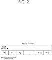
- FIG. 2 shows a downlink radio frame structure according to FDD of 3rd generation partnership project (3GPP) long term evolution (LTE).
- 3GPP 3rd generation partnership project
- LTE long term evolution
- the radio frame of FIG. 2 may be found in the section 5 of 3GPP TS 36.211 V10.4.0 (2011-12) "Evolved Universal Terrestrial Radio Access (E-UTRA); Physical Channels and Modulation (Release 10) ".
- the radio frame consists of 10 subframes.
- One subframe consists of two slots. Slots included in the radio frame are numbered with slot numbers 0 to 19.
- a time required to transmit one subframe is defined as a transmission time interval (TTI).
- TTI may be a scheduling unit for data transmission.
- one radio frame may have a length of 10 milliseconds (ms)
- one subframe may have a length of 1 ms
- one slot may have a length of 0.5 ms.
- the structure of the radio frame is for exemplary purposes only, and thus the number of subframes included in the radio frame or the number of slots included in the subframe may change variously.
- one slot may include a plurality of OFDM symbols.
- the number of OFDM symbols included in one slot may vary depending on a cyclic prefix (CP).
- CP cyclic prefix
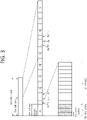
- FIG. 3 shows an example of a resource grid for one uplink or downlink slot in 3GPP LTE.
- the radio frame includes 10 sub-frames indexed 0 to 9.
- One sub-frame includes two consecutive slots.
- the time for one sub-frame to be transmitted is denoted TTI (transmission time interval).
- TTI transmission time interval
- the length of one sub-frame may be 1ms
- the length of one slot may be 0.5ms.
- One slot may include a plurality of OFDM (orthogonal frequency division multiplexing) symbols in the time domain.
- the OFDM symbol is merely to represent one symbol period in the time domain since 3GPP LTE adopts OFDMA (orthogonal frequency division multiple access) for downlink (DL), and thus, the multiple access scheme or name is not limited thereto.
- OFDM symbol may be denoted by other terms such as SC-FDMA (single carrier-frequency division multiple access) symbol or symbol period.
- one slot includes seven OFDM symbols.
- the number of OFDM symbols included in one slot may vary depending on the length of CP (cyclic prefix).
- CP cyclic prefix
- Resource block is a resource allocation unit and includes a plurality of sub-carriers in one slot. For example, if one slot includes seven OFDM symbols in the time domain and the resource block includes 12 sub-carriers in the frequency domain, one resource block may include 7x12 resource elements (REs).
- REs resource elements
- Sub-frames having index #1 and index #6 are denoted special sub-frames, and include a DwPTS (Downlink Pilot Time Slot: DwPTS), a GP (Guard Period) and an UpPTS (Uplink Pilot Time Slot).
- the DwPTS is used for initial cell search, synchronization, or channel estimation in a terminal.
- the UpPTS is used for channel estimation in the base station and for establishing uplink transmission sync of the terminal.
- the GP is a period for removing interference that arises on uplink due to a multi-path delay of a downlink signal between uplink and downlink.
- a DL (downlink) sub-frame and a UL (Uplink) co-exist in one radio frame.
- Table 1 shows an example of configuration of a radio frame.
- UL-DL Configuraiton Switch-point periodicity Subframe index 0 1 2 3 4 5 6 7 8 9 0 5 ms D S U U U D S U U U 1 5 ms D S U U D D S U U D 2 5 ms D S U D D D S U D D 3 10 ms D S U U U D D D D D D 4 10 ms D S U U D D D D D D 5 10 ms D S U D D D D D D D D 6 5 ms D S U U U U D S U U U D S U U D
- 'D' denotes a DL sub-frame
- 'U' a UL sub-frame
- 'S' a special sub-frame.
- the DL (downlink) sub-frame is split into a control region and a data region in the time domain.
- the control region includes up to three first OFDM symbols in the first slot of the sub-frame. However, the number of OFDM symbols included in the control region may be changed.
- a PDCCH and other control channels are assigned to the control region, and a PDSCH is assigned to the data region.
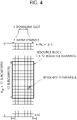
- FIG. 4 illustrates an example resource grid for one uplink or downlink slot in 3GPP LTE.
- the uplink slot includes a plurality of OFDM (orthogonal frequency division multiplexing) symbols in the time domain and N RB resource blocks (RBs) in the frequency domain.
- the number of resource blocks (RBs), i.e., N RB may be one from 6 to 110.
- one resource block includes 7x12 resource elements that consist of seven OFDM symbols in the time domain and 12 sub-carriers in the frequency domain.
- the number of sub-carriers in the resource block and the number of OFDM symbols are not limited thereto.
- the number of OFDM symbols in the resource block or the number of sub-carriers may be changed variously. In other words, the number of OFDM symbols may be varied depending on the above-described length of CP.
- 3GPP LTE defines one slot as having seven OFDM symbols in the case of CP and six OFDM symbols in the case of extended CP.
- OFDM symbol is to represent one symbol period, and depending on system, may also be denoted SC-FDMA symbol, OFDM symbol, or symbol period.
- the resource block is a unit of resource allocation and includes a plurality of sub-carriers in the frequency domain.
- the number of resource blocks included in the uplink slot, i.e., N UL is dependent upon an uplink transmission bandwidth set in a cell.
- Each element on the resource grid is denoted resource element.
- the number of sub-carriers in one OFDM symbol may be one of 128, 256, 512, 1024, 1536, and 2048.
- the resource grid for one uplink slot shown in FIG. 4 may also apply to the resource grid for the downlink slot.
- FIG. 5 illustrates the architecture of a downlink sub-frame.
- one slot includes seven OFDM symbols, by way of example.
- the number of OFDM symbols included in one slot may vary depending on the length of CP (cyclic prefix). That is, as described above, according to 3GPP TS 36.211 V10.4.0, one slot includes seven OFDM symbols in the normal CP and six OFDM symbols in the extended CP.
- Resource block is a unit for resource allocation and includes a plurality of sub-carriers in one slot. For example, if one slot includes seven OFDM symbols in the time domain and the resource block includes 12 sub-carriers in the frequency domain, one resource block may include 7x12 resource elements (REs).
- REs resource elements
- the DL (downlink) sub-frame is split into a control region and a data region in the time domain.
- the control region includes up to first three OFDM symbols in the first slot of the sub-frame. However, the number of OFDM symbols included in the control region may be changed.
- a PDCCH (physical downlink control channel) and other control channels are assigned to the control region, and a PDSCH is assigned to the data region.
- the physical channels in 3GPP LTE may be classified into data channels such as PDSCH (physical downlink shared channel) and PUSCH (physical uplink shared channel) and control channels such as PDCCH (physical downlink control channel), PCFICH (physical control format indicator channel), PHICH (physical hybrid-ARQ indicator channel) and PUCCH (physical uplink control channel).
- data channels such as PDSCH (physical downlink shared channel) and PUSCH (physical uplink shared channel) and control channels
- PDCCH physical downlink control channel
- PCFICH physical control format indicator channel
- PHICH physical hybrid-ARQ indicator channel
- PUCCH physical uplink control channel
- the PCFICH transmitted in the first OFDM symbol of the sub-frame carries CIF (control format indicator) regarding the number (i.e., size of the control region) of OFDM symbols used for transmission of control channels in the sub-frame.
- the wireless device first receives the CIF on the PCFICH and then monitors the PDCCH.
- the PCFICH is transmitted through a fixed PCFICH resource in the sub-frame without using blind decoding.
- the PHICH carries an ACK (positive-acknowledgement)/NACK (negative-acknowledgement) signal for a UL HARQ (hybrid automatic repeat request).
- the ACK/NACK signal for UL (uplink) data on the PUSCH transmitted by the wireless device is sent on the PHICH.
- the PBCH (physical broadcast channel) is transmitted in the first four OFDM symbols in the second slot of the first sub-frame of the radio frame.
- the PBCH carries system information necessary for the wireless device to communicate with the base station, and the system information transmitted through the PBCH is denoted MIB (master information block).
- MIB master information block
- SIB system information block
- the PDCCH may carry activation of VoIP (voice over internet protocol) and a set of transmission power control commands for individual UEs in some UE group, resource allocation of an higher layer control message such as a random access response transmitted on the PDSCH, system information on DL-SCH, paging information on PCH, resource allocation information of UL-SCH (uplink shared channel), and resource allocation and transmission format of DL-SCH (downlink-shared channel).
- a plurality of PDCCHs may be sent in the control region, and the terminal may monitor the plurality of PDCCHs.
- the PDCCH is transmitted on one CCE (control channel element) or aggregation of some consecutive CCEs.
- the CCE is a logical allocation unit used for providing a coding rate per radio channel's state to the PDCCH.
- the CCE corresponds to a plurality of resource element groups. Depending on the relationship between the number of CCEs and coding rates provided by the CCEs, the format of the PDCCH and the possible number of PDCCHs are determined.
- the control information transmitted through the PDCCH is denoted downlink control information (DCI).
- DCI may include resource allocation of PDSCH (this is also referred to as DL (downlink) grant), resource allocation of PUSCH (this is also referred to as UL (uplink) grant), a set of transmission power control commands for individual UEs in some UE group, and/or activation of VoIP (Voice over Internet Protocol).
- the base station determines a PDCCH format according to the DCI to be sent to the terminal and adds a CRC (cyclic redundancy check) to control information.
- the CRC is masked with a unique identifier (RNTI; radio network temporary identifier) depending on the owner or purpose of the PDCCH.
- RNTI unique identifier
- the terminal's unique identifier such as C-RNTI (cell-RNTI)
- a paging indicator for example, P-RNTI (paging-RNTI) may be masked to the CRC.
- SI-RNTI system information-RNTI
- RA-RNTI random access-RNTI
- blind decoding is used for detecting a PDCCH.
- the blind decoding is a scheme of identifying whether a PDCCH is its own control channel by demasking a desired identifier to the CRC (cyclic redundancy check) of a received PDCCH (this is referred to as candidate PDCCH) and checking a CRC error.
- the base station determines a PDCCH format according to the DCI to be sent to the wireless device, then adds a CRC to the DCI, and masks a unique identifier (this is referred to as RNTI (radio network temporary identifier) to the CRC depending on the owner or purpose of the PDCCH.
- RNTI radio network temporary identifier
- a control region in a subframe includes a plurality of control channel elements (CCEs).
- the CCE is a logical allocation unit used to provide the PDCCH with a coding rate depending on a radio channel state, and corresponds to a plurality of resource element groups (REGs).
- the REG includes a plurality of resource elements. According to an association relation of the number of CCEs and the coding rate provided by the CCEs, a PDCCH format and the number of bits of an available PDCCH are determined.
- One REG includes 4 REs.
- One CCE includes 9 REGs.
- the number of CCEs used to configure one PDCCH may be selected from a set ⁇ 1, 2, 4, 8 ⁇ . Each element of the set ⁇ 1, 2, 4, 8 ⁇ is referred to as a CCE aggregation level.
- the BS determines the number of CCEs used in transmission of the PDCCH according to a channel state. For example, a wireless device having a good DL channel state can use one CCE in PDCCH transmission. A wireless device having a poor DL channel state can use 8 CCEs in PDCCH transmission.
- a control channel consisting of one or more CCEs performs interleaving on an REG basis, and is mapped to a physical resource after performing cyclic shift based on a cell identifier (ID).
- ID cell identifier
- a UE is unable to know that the PDCCH of its own is transmitted on which position within control region and using which CCE aggregation level or DCI format. Since a plurality of PDCCHs may be transmitted in one subframe, the UE monitors a plurality of PDCCHs in every subframe. Here, the monitoring is referred to try to decode the PDCCH by the UE according to the PDCCH format.
- a search space is used.
- the search space may be referred to a monitoring set of CCE for the PDCCH.
- the UE monitors the PDCCH within the corresponding search space.
- the DCI format and the search space which is to be monitored are determined according to the transmission mode of the PDSCH.
- the table below represents an example of the PDCCH monitoring in which the C-RNTI is setup.
- Transmission mode DCI format Search space Transmission mode of PDSCH according to PDCCH Transmission mode 1 DCI format 1A Public service and terminal specific Single antenna port, port 0 DCI format 1 Terminal specific Single antenna port, port 0 Transmission mode 2 DCI format 1A Public service and terminal specific Transmit diversity DCI format 1 Terminal specific Transmit diversity Transmission mode 3 DCI format 1A Public service and terminal specific Transmit diversity DCI format 2A Terminal specific CDD(Cyclic Delay Diversity) or transmit diversity Transmission mode 4 DCI format 1A Public service and terminal specific Transmit diversity DCI format 2 Terminal specific Closed-loop spatial multiplexing Transmission mode 5 DCI format 1A Public service and terminal specific Transmit diversity DCI format 1D Terminal specific MU-MIMO(Multi-user Multiple Input Multiple Output) Transmission mode 6 DCI format 1A Public service and terminal specific Transmit diversity DCI format 1B Terminal specific Closed-loop spatial multiplexing Transmission mode 7 DCI format 1A Public service and terminal specific If the number of PBCH transmisison ports is 1, single antenna port, port 0.
- transmit Diversity MBSFN sub-frame port 7 as independent antenna port DCI format 2C Terminal specific 8 transmisison layers, ports 7-14 are used or port 7 or 8 is used as independent antenna port Transmission mode 10 DCI 1A Public service and terminal specific Non-MBSFN sub-frame: if the number of PBCH antenna ports is 1, port 0 is used as independent antenna port. Otherwise, transmit Diversity MBSFN sub-frame: port 7 as independent antenna port DCI format 2D Terminal specific 8 transmisison layers, ports 7-14 are used or port 7 or 8 is used as independent antenna port
- DCI format Contents DCI format 0 Used in PUSCH scheduling DCI format 1 Used in scheduling of one PDSCH codeword DCI format 1A Used in compact scheduling of one PDSCH codeword and random access process DCI format 1B Used in compact scheduling of one PDSCH codeword having precoding information DCI format 1C Used in very compact scheduling of one PDSCH codeword DCI format 1D Used in precoding and compact scheduling of one PDSCH codeword having power offset information DCI format 2 Used in PDSCH scheduling of terminals configured in closed-loop spatial multiplexing mode DCI format 2A Used in PDSCH scheduling of terminals configured in open-loop spatial multiplexing mode DCI format 2B DCI format 2B is used for resouce allocation for dual-layer beam-forming of PDSCH.
- DCI format 2C DCI format 2C is used for resouce allocation for closed-loop SU-MIMO or MU-MIMO operation to 8 layers.
- DCI format 2D DCI format 2C is used for resouce allocation to 8 layers.
- DCI format 3 Used to transmit TPC command of PUCCH and PUSCH having 2 bit power adjustments
- DCI format 3A Used to transmit TPC command of PUCCH and PUSCH having 1 bit power adjustment
- DCI format 4 Used in PUSCH scheduling of uplink (UP) operated in multi-antenna port transmisison mode
- the uplink channels include a PUSCH, a PUCCH, an SRS (Sounding Reference Signal), and a PRACH (physical random access channel).
- the PDCCH is monitored in an area restricted to the control region in the subframe, and a CRS transmitted in a full band is used to demodulate the PDCCH.
- a type of control data is diversified and an amount of control data is increased, scheduling flexibility is decreased when using only the existing PDCCH.
- an enhanced PDCCH is introduced.
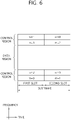
- FIG. 6 shows a structure of an uplink subframe in 3GPP LTE.
- the uplink subframe can be divided into a control region and a data region.
- a physical uplink control channel (PUCCH) for carrying uplink control information is allocated to the control region.
- a physical uplink shared channel (PUSCH) for carrying data is allocated to the data region.
- the PUCCH for one UE is allocated in an RB pair in a subframe. RBs belonging to the RB pair occupy different subcarriers in each of a first slot and a second slot. A frequency occupied by the RBs belonging to the RB pair to which the PUCCH is allocated changes at a slot boundary. This is called that the RB pair allocated to the PUCCH is frequency-hopped at the slot boundary.
- m is a location index indicating a logical frequency domain location of a RB pair allocated to a PUCCH in a subframe.
- Examples of the uplink control information transmitted on a PUCCH include hybrid automatic repeat request (HARQ), acknowledgement (ACK)/non-acknowledgement (NACK), channel quality indicator (CQI) indicating a DL channel state, scheduling request (SR) which is a UL radio resource allocation request, etc.
- HARQ hybrid automatic repeat request
- ACK acknowledgement
- NACK non-acknowledgement
- CQI channel quality indicator
- SR scheduling request which is a UL radio resource allocation request, etc.
- the PUSCH is mapped to an uplink shared channel (UL-SCH) which is a transport channel.
- Uplink data transmitted through the PUSCH may be a transport block which is a data block for the UL-SCH transmitted during a TTI.
- the transport block may be user information.
- the uplink data may be multiplexed data. The multiplexed data may be obtained by multiplexing the control information and a transport block for the UL-SCH.
- FIG. 7 illustrates an example of comparison between a single carrier system and a carrier aggregation system.
- CA carrier aggregation
- a plurality of component carriers (DL CC A to C, UL CC A to C) may be assigned to the terminal.
- Component carrier (CC) means the carrier used in then carrier aggregation system and may be briefly referred as carrier. For example, three 20MHz component carriers may be assigned so as to allocate a 60MHz bandwidth to the terminal.
- Carrier aggregation systems may be classified into a contiguous carrier aggregation system in which aggregated carriers are contiguous and a non-contiguous carrier aggregation system in which aggregated carriers are spaced apart from each other.
- a carrier aggregation system it should be understood as including both the case where the component carrier is contiguous and the case where the control channel is non-contiguous.
- the component carriers may use the bandwidth adopted in the existing system for backward compatibility with the existing system.
- the 3GPP LTE system supports bandwidths of 1.4MHz, 3MHz, 5MHz, 10MHz, 15MHz and 20MHz, and the 3GPP LTE-A system may configure a broad band of 20MHz or more only using the bandwidths of the 3GPP LTE system.
- new bandwidths may be defined to configure a wide band.
- the system frequency band of a wireless communication system is separated into a plurality of carrier frequencies.
- the carrier frequency means the cell frequency of a cell.
- the cell may mean a downlink frequency resource and an uplink frequency resource.
- the cell may refer to a combination of a downlink frequency resource and an optional uplink frequency resource.
- CA carrier aggregation
- the terminal In order for packet data to be transmitted/received through a specific cell, the terminal should first complete a configuration on the specific cell.
- the configuration means that reception of system information necessary for data transmission/reception on a cell is complete.
- the configuration may include an overall process of receiving common physical layer parameters or MAC (media access control) layers necessary for data transmission and reception or parameters necessary for a specific operation in the RRC layer.
- a configuration-complete cell is in the state where, once when receiving information indicating packet data may be transmitted, packet transmission and reception may be immediately possible.
- the cell that is in the configuration complete state may be left in an activation or deactivation state.
- activation means that data transmission or reception is being conducted or is in ready state.
- the terminal may monitor or receive a control channel (PDCCH) and a data channel (PDSCH) of the activated cell in order to identify resources (possibly frequency or time) assigned thereto.
- PDCCH control channel
- PDSCH data channel
- the "deactivation” means that transmission or reception of traffic data is impossible while measurement or transmission/reception of minimal information is possible.
- the terminal may receive system information (SI) necessary for receiving packets from the deactivated cell.
- SI system information
- the terminal does not monitor or receive a control channel (PDCCH) and data channel (PDSCH) of the deactivated cell in order to identify resources (probably frequency or time) assigned thereto.
- PDCH control channel
- PDSCH data channel
- Cells may be classified into primary cells and secondary cells, serving cells.
- the primary cell means a cell operating at a primary frequency.
- the primary cell is a cell where the terminal conducts an initial connection establishment procedure or connection reestablishment procedure with the base station or is a cell designated as a primary cell during the course of handover.
- the secondary cell means a cell operating at a secondary frequency.
- the secondary cell is configured once an RRC connection is established and is used to provide an additional radio resource.
- the serving cell is configured as a primary cell in case no carrier aggregation is configured or when the terminal cannot offer carrier aggregation.
- the term "serving cell" denotes a cell configured to the terminal and a plurality of serving cells may be included.
- One serving cell may consist of one downlink component carrier or a pair of ⁇ downlink component carrier, uplink component carrier ⁇ .
- a plurality of serving cells may consist of a primary cell and one or more of all the secondary cells.
- the carrier aggregation system may support a plurality of component carriers (CCs), i.e., a plurality of serving cells.
- CCs component carriers
- Such carrier aggregation system may support cross-carrier scheduling.
- the cross-carrier scheduling is a scheduling scheme that may conduct resource allocation of a PUSCH transmitted through other component carriers than the component carrier basically linked to a specific component carrier and/or resource allocation of a PDSCH transmitted through other component carriers through a PDCCH transmitted through the specific component carrier.
- the PDCCH and the PDSCH may be transmitted through different downlink CCs, and the PUSCH may be transmitted through an uplink CC other than the uplink CC linked to the downlink CC where the PDCCH including a UL grant is transmitted.
- the system supporting cross-carrier scheduling needs a carrier indicator indicating a DL CC/UL CC through which a PDSCH/PUSCH is transmitted where the PDCCH offers control information.
- the field including such carrier indicator is hereinafter denoted carrier indication field (CIF).
- the carrier aggregation system supporting cross-carrier scheduling may contain a carrier indication field (CIF) in the conventional DCI (downlink control information) format.
- CIF carrier indication field
- the cross-carrier scheduling-supportive carrier aggregation system for example, an LTE-A system, may have 3 bits expanded due to addition of the CIF to the existing DCI format (i.e., the DCI format used in the LTE system), and the PDCCH architecture may reuse the existing coding method or resource allocation method (i.e., CCE-based resource mapping).
- FIG. 8 exemplifies cross-carrier scheduling in the carrier aggregation system.
- the base station may configure a PDCCH monitoring DL CC (monitoring CC) set.
- the PDCCH monitoring DL CC set consists of some of all of the aggregated DL CCs, and if cross-carrier scheduling is configured, the user equipment performs PDCCH monitoring/decoding only on the DL CCs included in the PDCCH monitoring DL CC set.
- the base station transmits a PDCCH for PDSCH/PUSCH that is subject to scheduling only through the DL CCs included in the PDCCH monitoring DL CC set.
- the PDCCH monitoring DL CC set may be configured UE-specifically, UE group-specifically, or cell-specifically.
- FIG. 8 illustrates an example in which three DL CCs (DL CC A, DL CC B, and DL CC C) are aggregated, and DL CC A is set as a PDCCH monitoring DL CC.
- the user equipment may receive a DL grant for the PDSCH of DL CC A, DL CC B, and DL CC C through the PDCCH of DL CC A.
- the DCI transmitted through the PDCCH of DL CC A contains a CIF so that it may indicate which DL CC the DCI is for.
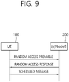
- FIG. 9 is a flow chart illsutrating a random access procedure in 3GPP LTE.
- a random access procedure is used to enable a UE 100 to obtain UL synchronzation with a base station, that is, an eNodeB 200 or to be allocated UL radio resource.
- the UE 100 receives a root index and a physical random access channel (PRACH) configuration index from the eNodeB 200.
- PRACH physical random access channel
- Each cell has 64 candidate random access preambles defined by a Zadoff-Chu (ZC) sequence, and the root index is a logical index for generating the 64 candidate random access preambles.
- ZC Zadoff-Chu
- the PRACH configuration index indicates a specific subframe in which a random access preamble can be transmitted and a preamble format.
- the UE 100 transmits an arbitrarily selected random access preamble to the eNodeB 200.
- the UE 100 selects one of the 64 candidate random access preambles.
- the eNodeB 200 also selects a subframe corresponding to the PRACH configuration index.
- the UE 100 transmits the seleted random access preamble in the selected subframe.
- the eNodeB 200 Upon receiving the random access preamble, the eNodeB 200 transmits a random access respnose (RAR) to the UE 100.
- the RAR is detected by two stages. First, the UE 100 detects a PDCCH masked with a random access (RA)-RNTI. The UE 100 receives an RAR of a medium access control (MAC) protocol data unit (PDU) on a PDSCH indicated by the detected PDCCH.
- MAC medium access control
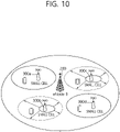
- next-generation mobile communciation system it is anticipated that a small cell having a small cell coverage radius is added to coverage of an existing cell and processes more traffic.
- the existing cell has coverage greater than that of the small cell, and thus, it is also termed a macro cell. This will be described with reference to FIG. 10 hereinafter.
- FIG. 10 is a view illustrating an environment of a heterogeneous network in which a macro cell and small cells coexist, which has a possibility of becoming a next-generation wireless communication system.
- a heterogeneous network environment in which a macro cell based on the existing eNodeB 200 overlaps small cells based on one or more small base stations (BSs) 300a, 300b, 300c, and 300d is illsutrated.
- the exsiting eNodeB 200 provides large coverage, relative to the small BSs, and thus, it is also called a macro eNodeB (MeNB).
- MeNB macro eNodeB
- a UE connected to the macro cell 200 may be termed a macro UE.
- the macro UE receives a downlink signal from the macro eNodeB, and transmits an uplink signal to the macro eNodeB.
- the macro cell by setting the macro cell to a primary cell (Pcell) and the small cells to secondary cells (Scell), a gap of coverage of the macro cell may be filled. Also, by setting the small cells to primary cells (Pcell) and the macro cell to a secondary cell (Scell), overall performance may be boosted.
- Pcell primary cell
- Scell secondary cell
- the small cells may use a frequency band currently allocated based on LTE/LTE-A, or may use a higher freuqency band (for example, a band of 3.5 GHz or higher).
- the LTE-A system also considers to use a small cell only as a macro-assisted small cell that may be used with the help of a macro cell, rather than being used independently, in the future.
- the small cells 300a, 300b, 300c, and 300d may have a similar channel environment, and since the small cells are positioned to be adjacent, interference therebetween may be problematic.
- the small cells 300b and 300c may expand or reduce coverage thereof.
- the expansion and reduction in coverage is termed cell breathing.
- the small cells 300b and 300c may be turned on or off according to situations.
- the small cells may use a frequency band currently allocated based on LTE/LTE-A, or may use a higher freuqency band (for example, a band of 3.5 GHz or higher).
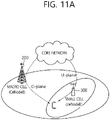
- the UE may be dually connected to the macro cell and the small cell. Scenarios in which dual connectivity is available are illsutrated in FIGS. 11A to 11D.
- FIGS. 11A and 11B illustrate scenarios of dual-connectivity available for a macro cell and a small cell.
- a UE may be set a mcro cell on a control- plane (C-plane) and may be set a small cell on a user-plane (U-plane).
- C-plane control- plane
- U-plane user-plane
- the UE may be set a small cell on the C-plane and may be set a macro cell on the U-plane.
- a cell of the C-plane will be referred to as a "C-Cell” and a cell of the U-plane will be referred to as a "U-Cell”.
- the aforementioned C-plane refers to supporting RRC connection configuration and re-configuration, an RRC idle mode, mobility including handover, cell selection, reselection, an HARQ process, configuration and reconfiguration of carrier aggregation (CA), a procedure required for RRC configuration, a random access procedure, and the like.
- the aforementioned U-plane refers to supporting processing of data of an application, CSI report, an HARQ process regarding application data, a multicasting/broadcasting service, and the like.
- setting of the C-plane and the U-plane is as follows.
- the C-Cell is set to a primary cell, and the U-Cell may be set to a secondary cell.
- the U-Cell may be set to a primary cell, and the C-Cell may be set to a secondary cell.
- the C-Cell may be particularly processed separately, and the U-Cell may be set to a primary cell.
- both the C-plane and the U-plane may be set to primary cells.
- it is assumed that the C-Cell is set to a primary cell and the U-Cell is set to a secondary cell.
- the UE may be set the macro cell as a C-cell or a primary cell and may be set the small cell as a U-cell or a secondary cell
- the macro cell may be constantly connected, as a primary cell, to the UE.
- the UE since the macro cell is a primary cell, the UE may transmit a PUCCH to the macro cell.
- the small cells may be disposed more densely and a growing number of UEs may be connected to the small cells. Accordingly, compared with a case in which an existing macro cell accommodates UEs solely, a larger number of UEs may be served.
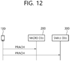
- the UE 100 may need to transmit a PRACH (for example, a random access preamble) to both the macro cell and the small cell.
- a PRACH for example, a random access preamble
- the current 3GPP standard specifications specify that the UE should not simultaneously transmit a plurality of PRACHs.
- a situation in which a plurality of PRACHs should be transmitted will be described with reference to FIG. 12 .
- FIG. 12 is a view illustrating an example in which a UE transmits a PRACH to a plurality of cells.
- the UE may transmit a PRACH to each of the macro cell 200 and the small cell 300.
- the UE may generate a random access preamble for the macro cell 200 and also generate a random access preamble for the small cell 300. Thereafter, the UE may separately transmit the two random access preambles.
- the UE transmitting the PRACHs to each of the macro cell 200 and the small cell 300 may be effective when the macro cell 200 and the small cell 300 are geographically away from one another so a real-time characteristics of a backhaul link between the macro cell 200 and the small cell 300 is low. Also, in such a case, the UE requires independently performing timing adjustment and making a scheduling request for the macro cell 200 and the small cell 3000. Meanwhile, in a case in which the number of small cells is large, the UE may independently require performing timing adjustment and making a scheduling request with respect to each cell or each cell group (for example, a master cell group or a secondary cell group).
- each cell or each cell group for example, a master cell group or a secondary cell group.
- the PRACH may be used for an initial access, may transmit a scheduling request, or may be triggered by a PDCCH order (order) or a MAC layer request. Or, the PRACH may be periodically transmitted in order to monitor signal quality of the UE.
- the two PRACH may collide on the same subframe.
- PRACHs for each cell may collide on the same subframe.
- a first embodiment of the present dislcousre proposes a method for preventing collision bewteen a plurality of PRACHs on the same subframe when a UE does not have capability of simultaneously transmitting the plurality of PRACHs (for example, random access preamble). Also, the first embodiment of the present disclosure proposes a UE handling procedure when a plurality of PRACHs collide on the same subframe when the UE does not have capability of simultaneously transmitting the plurality of PRACHs. Also, a second emboidment of the present disclosure proposes a process of the UE when the UE has capability of simultaneously transmitting a plurality of PRACHs. Here, UE transmitting a plurality of PRACHs may be considered as capability of the UE.
- the UE When the UE is able to simultaneously transmit a PUCCH and a PUCCH, it may be assumed that the UE has capability of simultaneously transmitting a plurality of PRACHs. Or, it may also be assumed that the UE supporting dual connectivity has capability of simultaneously transmitting a PUCCH and a PUCCH, capability of simultaneously transmitting a PUCCH and a PUSCH, and capability of simultaneously transmitting a plurality of PRACHs.
- next-generation system it is possible or impossible to simultaneously transmit a plurality of PRACHs according to capability of a UE.
- the number of PRACH that may be transmited on a single subframe is limtied to 1.
- a PRACH is independently transmitted by each eNodeB, and PRACHs is triggered to be simultaneously transmitted at the same ponit in time (for example, in the same subframe).
- a UE needs to select one of a pluirality of colliding PRACHs, and when a prioirty rule is set in this case, the folowing items may be considered.
- a primary cell has high priority and, among secondary cells, and secondary cells is set to have priority in order, starting from one having a lowest secondary cell index. Or, it is also considered that a primary cell has high priority, and thereafter, among secondary cells, priority of a cell capable of transmitting a PUCCH is set to be high.
- a priority rule is determined according to a master cell group as an aggregate including a primary cell or an aggregate of cells corresponding a master eNodeB and a secondary cell group as an aggregate of cells corresponding to a secondary eNodeB.
- cells corresponding to the master cell group have priority higher than that of cells corresponding to the secondary cell group.
- a cell operating as a primary cell for example, a primary cell or a second primary cell
- cells are set to have priority, starting from one having the lowest cell index.
- a primary cell has highest priority
- a second primary cell (SeNB or a primary cell of a second carrier group or a cell in which a PUCCH is transmitted) has a second-highest priority. Thereafter, priority of a secondary cell corresponding to a secondary cell group is set to be high.
- a primary cell has the highest priority
- a second primary cell has a second-highest priority. Thereafter, a priority of a secondary cell corresponding to a master cell group is set to be high.
- a primary cell has a highest priority
- a second primary cell has a second-highest priority. Thereafter, priority is set to be high, starting from one having a lowest cell index.
- contention-based PRACH transmission may have priority over contention-free PRACH transmission. If a UE attempts at contention-based PRACH transmission with respect to both of two cells, the primary cell may have a highest priority. Based on this, a secondary primary cell may have a second-highest priority. Thereafter, a priority may be set to be high, starting from a cell having a lowest cell index.
- Contention-free-based PRACH transmission may have a higher priority. The reason is because contention-free-based PRACH transmission triggered by a cell has priority. This may be applied when PRACH transmissions of cells having the same priority collide with each other.
- a contention-based PRACH has priority. This may be applied when PRACH transmissions of cells having the same priority collide with each other.
- a high priority may be set for a PRACH transmission regarding a cell in a good state according to pathloss or a measurement result such as an RSRP, or the like, from a received reference signal (RS).
- RS received reference signal
- a priority of a corresponding PRACH may be set to be higher as a logical index thereof is lower. This is to transmit a PRACH having good CM characteristics.
- a PRACH may be set to have a higher priority, starting from one having a small target cell radius.
- priority may be set in order of PRACH format 4 (which corresponds in a TDD or TDD-FDD situation), PRACH format 0, PRACH format 2, PRACH format 1, and PRACH format 3.
- a priority may be set in association with the number of retransmissions of a PRACH. For example, when the numbers of retransmission attempts of two PRACHs are different, a PRACH which has been retransmitted more frequently may have a priority. In order to support this, a higher layer may inform about the retransmission number when each PRACH is requested to be transmitted.
- a priority may be set on the basis of transmission power of a PRACH.
- a PRACH having greater transmission power may have a higher priority.
- a side having a smaller number of uplink subframes according to PRACH configuration for PRACH transmission, a side having a greater size according to a preamble format, a TDD according to a duplex mode, or an extended CP according to a cyclic prefix (CP) may be considered to be set to have a higher priority.
- the priority may also be applied in the opposite way.
- the contents described above are merely based on the references when a priority is considered, for example, and application of different priority may not be excluded.
- the references described above may be combined to be used.
- a situation in which the PRACHs are currently transmitted is considered. For example, when a PRACH is transmitted on a subframe i (which overlaps subframes j+1 and j+2) in a master cell group (MCG) in a situation in which a PRACH preamble format 3 is selected and a PRACH is transmtited across subframes j, j+1, and j+2 in a secondary cell group (SCG), in order to prioritize PRACH transmission to the master cell group (MCG), the PRACH to the secondary cell group (SCG) needs to be stopped.
- MCG master cell group
- SCG secondary cell group
- PCmax maximum transmission power
- a PRACH having a lower priority may be dropped, delayed, or power-scaled.
- a PRACH having a lower priority may be dropped, delayed, or power-scaled.
- transmission of an ongoing PRACH is prioritized.
- a PRACH, which is not ongoing PRACH transmission may be dropped.
- a start point of PRACH transmission having a lower priority comes later than a start point of PRACH transmission having a higher priority
- the UE may drop the PRACH having a lower priority or may perform power scaling. If the start point comes earlier, the second scheme is applied. This will be described in more detail with reference to FIG. 13 .
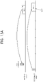
- FIGS. 13A and 13B illustrate an example in which any one PRACH transmission is dropped.
- a priority of PRACH transmission regarding a secondary cell group is lower than a priority of PRACH transmission regarding a master cell group.
- PRACH to the secondary cell group may be dropped before being transmitted.
- PRACH transmission to the secondary cell group is continued and PRACH transmission to the primary cell group may be delayed or dropped.
- a priority of a PRACH may be set to be higher than a priority of other channel.
- transmission power is uniform for PUCCH and DM-RS transmission.
- the PRACH to the primary cell may have a priority set to be higher than a priority of the other PRACH.
- a priority of an ongoing PRACH may be set to be higher.
- a PRACH having a lower priority may be dropped. Meanwhile, it may be assumed that uniform transmission power is used during transmission of a PRACH.
- a PRACH which has not been transmitted but remains is to be transmitted, after a UE first transmits any one selected PRACH by applying the priority rule as described above. Simply, it may be assumed that the PRACH which has not been transmitteed is dropped. However, in case of contention-based PRACH transmission, the UE may select a transmission timing, and thus, in order to avoid collision, one PRACH may be first transmitted and transmission of the other PRACH may be delayed in timing, whereby both the two PRACHs may be transmitted.
- the cell which has transmitted the PDCCH order may informt the corresopnding UE that a timing of +j is permitted.
- a PRACH is transmitted according to a PDCCH order
- a PRACH is transmitted on the earliest subframe able to transmit a PRACH after n+k or n+k+j (k is a PRACH timing reference corresponding to current PDCCH order) in consideration of a situation in which two cells simultaneously transmit a PDCCH cmomand
- the UE may transmit the two PRACHs one by one.
- a contention-based PRACH transmission is requested according to a PDCCH order
- transmission of a contention-based PRACH has a prioirty higher than that of transmission of a contention-free-based PRACH even though the both PRACHs are simultanously requsted by the same PDCCH order.
- a PRACH based on a PDCCH order may have a higher priority.
- the two PRACHs may be trasnmitted on the earliest subframe capable of tnrasmitting a PRACH after n+k or n+k+j.
- the UE in a case in which the UE drops transmission of another PRACH as mentioned above, since transmission of the PRACH has not failed but simply a transmission opportunity was lost, and thus, it may be distinguished to be different from a general PRACH retransmission.
- a lower layer of the UE may consider to transmit an indication that the PRACH was dropped to a higher layer, and thus, the higher layer may not cause the lower layer to perform an operation for enhancing PRACH performance such as power ramping, or the like, according to the received indication.
- the higher layer may not increase a preamble transmission counter (PREAMBLE_TRANSMISSION_COUNTER), thereby preventing a case in which a maximum transmission number is reached.
- PREAMBLE_TRANSMISSION_COUNTER preamble transmission counter
- the higher layer may attempt at retransmission of the PRACH immediately again, and in this case, retransmission counter or power is not determined again but previous power may be used as is, or retransmission may be increased and only when a retransmission counter reaches the maximum, the PRACH may be transmitted by previous power.
- the higher layer may not declare radio link failure (RLF).
- RLF radio link failure
- the UE may perform power ramping in the same manner as that of the existing scheme or may increase a preamble transmission counter (for example, PREAMBLE_TRANSMISSION_COUNTER).
- PREAMBLE_TRANSMISSION_COUNTER a preamble transmission counter
- the higher layer may trigger RLF regarding the corresponding cell.
- the UE may consider to transmit an RLF indication regarding a secondary cell (or a second primary cell or a cell performing a function of SeNB or a primary cell or transmitting a PUCCH) to the primary cell (or MeNB), and in this case, the corresponding RLF may be set in the form of expressing with reference to PRACH detection failure (in particular, according to dropping of PRACH transmission).
- a second embodioment of the present disclosure proposes a procedure of a UE when the UE is able to simultaneously tnarsmit a plruality of PRACHs.
- UE transmitting a plurality of PRACHs may be considered capability of the UE.
- the UE may simultaneously transmit the plurality of PRACHs only when the corresponding capability is set to be activated in actuality.
- a priority rule regading power regarding a PRACH to which cell is to be adjusted may use the references described above in the first embodiment.
- a boundary of a downlink subframe used as a refeence may not be matched in each PRACH tarnsmission.
- power may be adjusted with reference to a portion corresponding to a maximum value in the overlap section.
- the UE transmits PRACHs to a plurality of cell groups, it may be assumed that the UE a random access response (RAR) is received from a specific cell in which a PUCCH can be transmitted in each cell group.
- RAR random access response
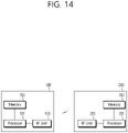
- Fig. 14 is a block diagram illustrating a wireless communication system in which a disclosure of the present specification is implemented
- a BS 200 includes a processor 201, a memory 202, and an RF (radio frequency) unit (the MTC device) 203.
- the memory 202 which is coupled to the processor 201 stores a variety of information for driving the processor 201.
- the RF unit 203 which is coupled to the processor 201 transmits and/or receives a radio signal.
- the processor 201 implements the proposed functions, procedure, and/or methods. In the embodiments described above, the operation of BS may be implemented by the processor 201
- a user equipment (UE) 100 includes a processor 101, a memory 102, and an RF (radio frequency) unit 103.
- the memory 102 which is coupled to the processor 101 stores a variety of information for driving the processor 101.
- the RF unit 103 which is coupled to the processor 101 transmits and/or receives a radio signal.
- the processor 101 implements the proposed functions, procedure, and/or methods
- the processor may include Application-Specific Integrated Circuits (ASICs), other chipsets, logic circuits, and/or data processors.
- the memory may include Read-Only Memory (ROM), Random Access Memory (RAM), flash memory, memory cards, storage media and/or other storage devices.
- the RF unit may include a baseband circuit for processing a radio signal.
- the above-described scheme may be implemented using a module (process or function) which performs the above function.
- the module may be stored in the memory and executed by the processor.
- the memory may be disposed to the processor internally or externally and connected to the processor using a variety of well-known means
Landscapes
- Engineering & Computer Science (AREA)
- Computer Networks & Wireless Communication (AREA)
- Signal Processing (AREA)
- Computer Security & Cryptography (AREA)
- Mobile Radio Communication Systems (AREA)
Description
- The present invention relates to a method (claim 1) and an apparatus (claim 7) for performing random access procedure.
- 3rd generation partnership project (3GPP) long term evolution (LTE) evolved from a universal mobile telecommunications system (UMTS) is introduced as the
3GPP release 8. The 3GPP LTE uses orthogonal frequency division multiple access (OFDMA) in a downlink, and uses single carrier-frequency division multiple access (SC-FDMA) in an uplink. - Such LTE may be divided into a frequency division duplex (FDD) type and a time division duplex (TDD) type.
- As set forth in 3GPP TS 36.211 V10.4.0, the physical channels in 3GPP LTE may be classified into data channels such as PDSCH (physical downlink shared channel) and PUSCH (physical uplink shared channel) and control channels such as PDCCH (physical downlink control channel), PCFICH (physical control format indicator channel), PHICH (physical hybrid-ARQ indicator channel) and PUCCH (physical uplink control channel).
- Meanwhile, in order to process a growing number of data, in a next-generation mobile communication system, a small cell having a small cell coverage radius is anticipated to be added to coverage of an existing cell and process more traffic.
- Here, however, as a small cell is introduced, a terminal may need to perform a random access procedure in both of a macro cell and a small cell, but it is not permitted according to the current 3GPP standard specification.
- Accordingly, a disclosure of the present specification has been made in an effort to solve the aforementioned problem.
- The invention is defined in the appended claims. In the present description and drawings, any examples and technical descriptions of apparatuses, products and/or methods which are not covered by the claims should be taken as background art or examples useful for understanding the invention. In order to achieve the aforementioned purpose, one disclosure of the present specification provides a method for performing a random access procedure as set forth in the appended claims.
- In order to achieve the aforementioned purpose, one disclosure of the present specification provides a user equipment (UE) as set forth in the appended claims.
- According to a disclosure of the present invention, the above problem of the related art is solved.
-
-
FIG. 1 illustrates a wireless communication system. -
FIG. 2 illustrates the architecture of a radio frame according to frequency division duplex (FDD) of 3rd generation partnership project (3GPP) long term evolution (LTE). -
FIG. 3 illustrates the architecture of a downlink radio frame according to time division duplex (TDD) in 3GPP LTE. -
FIG. 4 illustrates an example resource grid for one uplink or downlink slot in 3GPP LTE. -
FIG. 5 illustrates the architecture of a downlink subframe. -
FIG. 6 illustrates the architecture of an uplink subframe in 3GPP LTE. -
FIG. 7 illustrates an example of comparison between a single carrier system and a carrier aggregation system. -
FIG. 8 exemplifies cross-carrier scheduling in a carrier aggregation system. -
FIG 9 is a flow chart illustrating a random access procedure in 3GPP LTE. -
FIG. 10 is a view illustrating an environment of a heterogeneous network in which a macro cell and small cells coexist, which has a possibility of becoming a next-generation wireless communication system. -
FIGS. 11A and11B illustrate scenarios of dual-connectivity available for a macro cell and a small cell. -
FIG. 12 is a view illustrating an example in which a UE transmits a PRACH to a plurality of cells. -
FIGS. 13A and13B illustrate an example in which any one PRACH transmission is dropped. -
FIG. 14 is a block diagram illustrating a wireless communication system. - Hereinafter, based on 3rd Generation Partnership Project (3GPP) long term evolution (LTE) or 3GPP LTE-advanced (LTE-A), the present invention will be applied. This is just an example, and the present invention may be applied to various wireless communication systems. Hereinafter, LTE includes LTE and/or LTE-A.
- The technical terms used herein are used to merely describe specific embodiments and should not be construed as limiting the present invention. Further, the technical terms used herein should be, unless defined otherwise, interpreted as having meanings generally understood by those skilled in the art but not too broadly or too narrowly. Further, the technical terms used herein, which are determined not to exactly represent the invention, should be replaced by or understood by such technical terms as being able to be exactly understood by those skilled in the art. Further, the general terms used herein should be interpreted in the context as defined in the dictionary, but not in an excessively narrowed manner.
- The expression of the singular number in the specification includes the meaning of the plural number unless the meaning of the singular number is definitely different from that of the plural number in the context. In the following description, the term 'include' or 'have' may represent the existence of a feature, a number, a step, an operation, a component, a part or the combination thereof described in the specification, and may not exclude the existence or addition of another feature, another number, another step, another operation, another component, another part or the combination thereof.
- The terms 'first' and 'second' are used for the purpose of explanation about various components, and the components are not limited to the terms 'first' and 'second'. The terms 'first' and 'second' are only used to distinguish one component from another component. For example, a first component may be named as a second component without deviating from the scope of the present invention.
- It will be understood that when an element or layer is referred to as being "connected to" or "coupled to" another element or layer, it can be directly connected or coupled to the other element or layer or intervening elements or layers may be present. In contrast, when an element is referred to as being "directly connected to" or "directly coupled to" another element or layer, there are no intervening elements or layers present.
- Hereinafter, exemplary embodiments of the present invention will be described in greater detail with reference to the accompanying drawings. In describing the present invention, for ease of understanding, the same reference numerals are used to denote the same components throughout the drawings, and repetitive description on the same components will be omitted. Detailed description on well-known arts which are determined to make the gist of the invention unclear will be omitted. The accompanying drawings are provided to merely make the invention readily understood, but not should be intended to be limiting of the invention. It should be understood that the invention may be expanded to its modificationsor replacements in addition to what is shown in the drawings.
- As used herein, 'base station' generally refers to a fixed station that communicates with a wireless device and may be denoted by other terms such as eNB (evolved-NodeB), BTS (base transceiver system), or access point.
- As used herein, user equipment (UE) may be stationary or mobile, and may be denoted by other terms such as device, wireless device, terminal, MS(mobile station), UT(user terminal), SS(subscriber station), MT(mobile terminal) and etc.
-
FIG. 1 shows a wireless communication system. - Referring to
Fig. 1 , the wireless communication system includes at least one base station (BS) 20. Respective BSs 20 provide a communication service to particulargeographical areas - The UE generally belongs to one cell and the cell to which the terminal belong is referred to as a serving cell. A base station that provides the communication service to the serving cell is referred to as a serving BS. Since the wireless communication system is a cellular system, another cell that neighbors to the serving cell is present. Another cell which neighbors to the serving cell is referred to a neighbor cell. Abase station that provides the communication service to the neighbor cell is referred to as a neighbor BS. The serving cell and the neighbor cell are relatively decided based on the UE.
- Hereinafter, a downlink means communication from the base station 20 to the
terminal 10 and an uplink means communication from theterminal 10 to the base station 20. In the downlink, a transmitter may be a part of the base station 20 and a receiver may be a part of theterminal 10. In the uplink, the transmitter may be a part of the terminal 10 and the receiver may be a part of the base station 20. - Meanwhile, the wireless communication system may be any one of a multiple-input multiple-output (MIMO) system, a multiple-input single-output (MISO) system, a single-input single-output (SISO) system, and a single-input multiple-output (SIMO) system. The MIMO system uses a plurality of transmit antennas and a plurality of receive antennas. The MISO system uses a plurality of transmit antennas and one receive antenna. The SISO system uses one transmit antenna and one receive antenna. The SIMO system uses one transmit antenna and one receive antenna. Hereinafter, the transmit antenna means a physical or logical antenna used to transmit one signal or stream and the receive antenna means a physical or logical antenna used to receive one signal or stream.
- Meanwhile, the wireless communication system may be generally divided into a frequency division duplex (FDD) type and a time division duplex (TDD) type. According to the FDD type, uplink transmission and downlink transmission are achieved while occupying different frequency bands. According to the TDD type, the uplink transmission and the downlink transmission are achieved at different time while occupying the same frequency band. A channel response of the TDD type is substantially reciprocal. This means that a downlink channel response and an uplink channel response are approximately the same as each other in a given frequency area. Accordingly, in the TDD based wireless communication system, the downlink channel response may be acquired from the uplink channel response. In the TDD type, since an entire frequency band is time-divided in the uplink transmission and the downlink transmission, the downlink transmission by the base station and the uplink transmission by the terminal may not be performed simultaneously. In the TDD system in which the uplink transmission and the downlink transmission are divided by the unit of a subframe, the uplink transmission and the downlink transmission are performed in different subframes.
- Hereinafter, the LTE system will be described in detail.
-
FIG. 2 shows a downlink radio frame structure according to FDD of 3rd generation partnership project (3GPP) long term evolution (LTE). - The radio frame of
FIG. 2 may be found in thesection 5 of 3GPP TS 36.211 V10.4.0 (2011-12) "Evolved Universal Terrestrial Radio Access (E-UTRA); Physical Channels and Modulation (Release 10)". - Referring to
FIG. 2 , the radio frame consists of 10 subframes. One subframe consists of two slots. Slots included in the radio frame are numbered withslot numbers 0 to 19. A time required to transmit one subframe is defined as a transmission time interval (TTI). The TTI may be a scheduling unit for data transmission. For example, one radio frame may have a length of 10 milliseconds (ms), one subframe may have a length of 1 ms, and one slot may have a length of 0.5 ms. - The structure of the radio frame is for exemplary purposes only, and thus the number of subframes included in the radio frame or the number of slots included in the subframe may change variously.
- Meanwhile, one slot may include a plurality of OFDM symbols. The number of OFDM symbols included in one slot may vary depending on a cyclic prefix (CP).
-
FIG. 3 shows an example of a resource grid for one uplink or downlink slot in 3GPP LTE. - For this, 3GPP TS 36.211 V10.4.0 (2011-12) "Evolved Universal Terrestrial Radio Access (E-UTRA); Physical Channels and Modulation (Release 8)", Ch. 4 may be referenced, and this is for TDD (time division duplex).
- The radio frame includes 10 sub-frames indexed 0 to 9. One sub-frame includes two consecutive slots. The time for one sub-frame to be transmitted is denoted TTI (transmission time interval). For example, the length of one sub-frame may be 1ms, and the length of one slot may be 0.5ms.
- One slot may include a plurality of OFDM (orthogonal frequency division multiplexing) symbols in the time domain. The OFDM symbol is merely to represent one symbol period in the time domain since 3GPP LTE adopts OFDMA (orthogonal frequency division multiple access) for downlink (DL), and thus, the multiple access scheme or name is not limited thereto. For example, OFDM symbol may be denoted by other terms such as SC-FDMA (single carrier-frequency division multiple access) symbol or symbol period.
- By way of example, one slot includes seven OFDM symbols. However, the number of OFDM symbols included in one slot may vary depending on the length of CP (cyclic prefix). According to 3GPP TS 36.211 V8.7.0, one slot, in the normal CP, includes seven OFDM symbols, and in the extended CP, includes six OFDM symbols.
- Resource block (RB) is a resource allocation unit and includes a plurality of sub-carriers in one slot. For example, if one slot includes seven OFDM symbols in the time domain and the resource block includes 12 sub-carriers in the frequency domain, one resource block may include 7x12 resource elements (REs).
- Sub-frames having
index # 1 andindex # 6 are denoted special sub-frames, and include a DwPTS (Downlink Pilot Time Slot: DwPTS), a GP (Guard Period) and an UpPTS (Uplink Pilot Time Slot). The DwPTS is used for initial cell search, synchronization, or channel estimation in a terminal. The UpPTS is used for channel estimation in the base station and for establishing uplink transmission sync of the terminal. The GP is a period for removing interference that arises on uplink due to a multi-path delay of a downlink signal between uplink and downlink. - In TDD, a DL (downlink) sub-frame and a UL (Uplink) co-exist in one radio frame. Table 1 shows an example of configuration of a radio frame.
[Table 1] UL-DL Configuraiton Switch-point periodicity Subframe index 0 1 2 3 4 5 6 7 8 9 0 5 ms D S U U U D S U U U 1 5 ms D S U U D D S U U D 2 5 ms D S U D D D S U D D 3 10 ms D S U U U D D D D D 4 10 ms D S U U D D D D D D 5 10 ms D S U D D D D D D D 6 5 ms D S U U U D S U U D - 'D' denotes a DL sub-frame, 'U' a UL sub-frame, and 'S' a special sub-frame. When receiving a UL-DL configuration from the base station, the terminal may be aware of whether a sub-frame is a DL sub-frame or a UL sub-frame according to the configuration of the radio frame.
- The DL (downlink) sub-frame is split into a control region and a data region in the time domain. The control region includes up to three first OFDM symbols in the first slot of the sub-frame. However, the number of OFDM symbols included in the control region may be changed. A PDCCH and other control channels are assigned to the control region, and a PDSCH is assigned to the data region.
-
FIG. 4 illustrates an example resource grid for one uplink or downlink slot in 3GPP LTE. - Referring to
FIG. 4 , the uplink slot includes a plurality of OFDM (orthogonal frequency division multiplexing) symbols in the time domain and NRB resource blocks (RBs) in the frequency domain. For example, in the LTE system, the number of resource blocks (RBs), i.e., NRB, may be one from 6 to 110. - Here, by way of example, one resource block includes 7x12 resource elements that consist of seven OFDM symbols in the time domain and 12 sub-carriers in the frequency domain. However, the number of sub-carriers in the resource block and the number of OFDM symbols are not limited thereto. The number of OFDM symbols in the resource block or the number of sub-carriers may be changed variously. In other words, the number of OFDM symbols may be varied depending on the above-described length of CP. In particular, 3GPP LTE defines one slot as having seven OFDM symbols in the case of CP and six OFDM symbols in the case of extended CP.
- OFDM symbol is to represent one symbol period, and depending on system, may also be denoted SC-FDMA symbol, OFDM symbol, or symbol period. The resource block is a unit of resource allocation and includes a plurality of sub-carriers in the frequency domain. The number of resource blocks included in the uplink slot, i.e., NUL, is dependent upon an uplink transmission bandwidth set in a cell. Each element on the resource grid is denoted resource element.
- Meanwhile, the number of sub-carriers in one OFDM symbol may be one of 128, 256, 512, 1024, 1536, and 2048.
- In 3GPP LTE, the resource grid for one uplink slot shown in
FIG. 4 may also apply to the resource grid for the downlink slot. -
FIG. 5 illustrates the architecture of a downlink sub-frame. - In
FIG. 5 , assuming the normal CP, one slot includes seven OFDM symbols, by way of example. However, the number of OFDM symbols included in one slot may vary depending on the length of CP (cyclic prefix). That is, as described above, according to 3GPP TS 36.211 V10.4.0, one slot includes seven OFDM symbols in the normal CP and six OFDM symbols in the extended CP. - Resource block (RB) is a unit for resource allocation and includes a plurality of sub-carriers in one slot. For example, if one slot includes seven OFDM symbols in the time domain and the resource block includes 12 sub-carriers in the frequency domain, one resource block may include 7x12 resource elements (REs).
- The DL (downlink) sub-frame is split into a control region and a data region in the time domain. The control region includes up to first three OFDM symbols in the first slot of the sub-frame. However, the number of OFDM symbols included in the control region may be changed. A PDCCH (physical downlink control channel) and other control channels are assigned to the control region, and a PDSCH is assigned to the data region.
- The physical channels in 3GPP LTE may be classified into data channels such as PDSCH (physical downlink shared channel) and PUSCH (physical uplink shared channel) and control channels such as PDCCH (physical downlink control channel), PCFICH (physical control format indicator channel), PHICH (physical hybrid-ARQ indicator channel) and PUCCH (physical uplink control channel).
- The PCFICH transmitted in the first OFDM symbol of the sub-frame carries CIF (control format indicator) regarding the number (i.e., size of the control region) of OFDM symbols used for transmission of control channels in the sub-frame. The wireless device first receives the CIF on the PCFICH and then monitors the PDCCH.
- Unlike the PDCCH, the PCFICH is transmitted through a fixed PCFICH resource in the sub-frame without using blind decoding.
- The PHICH carries an ACK (positive-acknowledgement)/NACK (negative-acknowledgement) signal for a UL HARQ (hybrid automatic repeat request). The ACK/NACK signal for UL (uplink) data on the PUSCH transmitted by the wireless device is sent on the PHICH.
- The PBCH (physical broadcast channel) is transmitted in the first four OFDM symbols in the second slot of the first sub-frame of the radio frame. The PBCH carries system information necessary for the wireless device to communicate with the base station, and the system information transmitted through the PBCH is denoted MIB (master information block). In comparison, system information transmitted on the PDSCH indicated by the PDCCH is denoted SIB (system information block).
- The PDCCH may carry activation of VoIP (voice over internet protocol) and a set of transmission power control commands for individual UEs in some UE group, resource allocation of an higher layer control message such as a random access response transmitted on the PDSCH, system information on DL-SCH, paging information on PCH, resource allocation information of UL-SCH (uplink shared channel), and resource allocation and transmission format of DL-SCH (downlink-shared channel). A plurality of PDCCHs may be sent in the control region, and the terminal may monitor the plurality of PDCCHs. The PDCCH is transmitted on one CCE (control channel element) or aggregation of some consecutive CCEs. The CCE is a logical allocation unit used for providing a coding rate per radio channel's state to the PDCCH. The CCE corresponds to a plurality of resource element groups. Depending on the relationship between the number of CCEs and coding rates provided by the CCEs, the format of the PDCCH and the possible number of PDCCHs are determined.
- The control information transmitted through the PDCCH is denoted downlink control information (DCI). The DCI may include resource allocation of PDSCH (this is also referred to as DL (downlink) grant), resource allocation of PUSCH (this is also referred to as UL (uplink) grant), a set of transmission power control commands for individual UEs in some UE group, and/or activation of VoIP (Voice over Internet Protocol).
- The base station determines a PDCCH format according to the DCI to be sent to the terminal and adds a CRC (cyclic redundancy check) to control information. The CRC is masked with a unique identifier (RNTI; radio network temporary identifier) depending on the owner or purpose of the PDCCH. In case the PDCCH is for a specific terminal, the terminal's unique identifier, such as C-RNTI (cell-RNTI), may be masked to the CRC. Or, if the PDCCH is for a paging message, a paging indicator, for example, P-RNTI (paging-RNTI) may be masked to the CRC. If the PDCCH is for a system information block (SIB), a system information identifier, SI-RNTI (system information-RNTI), may be masked to the CRC. In order to indicate a random access response that is a response to the terminal's transmission of a random access preamble, an RA-RNTI (random access-RNTI) may be masked to the CRC.
- In 3GPP LTE, blind decoding is used for detecting a PDCCH. The blind decoding is a scheme of identifying whether a PDCCH is its own control channel by demasking a desired identifier to the CRC (cyclic redundancy check) of a received PDCCH (this is referred to as candidate PDCCH) and checking a CRC error. The base station determines a PDCCH format according to the DCI to be sent to the wireless device, then adds a CRC to the DCI, and masks a unique identifier (this is referred to as RNTI (radio network temporary identifier) to the CRC depending on the owner or purpose of the PDCCH.
- A control region in a subframe includes a plurality of control channel elements (CCEs). The CCE is a logical allocation unit used to provide the PDCCH with a coding rate depending on a radio channel state, and corresponds to a plurality of resource element groups (REGs). The REG includes a plurality of resource elements. According to an association relation of the number of CCEs and the coding rate provided by the CCEs, a PDCCH format and the number of bits of an available PDCCH are determined.
- One REG includes 4 REs. One CCE includes 9 REGs. The number of CCEs used to configure one PDCCH may be selected from a set {1, 2, 4, 8}. Each element of the set {1, 2, 4, 8} is referred to as a CCE aggregation level.
- The BS determines the number of CCEs used in transmission of the PDCCH according to a channel state. For example, a wireless device having a good DL channel state can use one CCE in PDCCH transmission. A wireless device having a poor DL channel state can use 8 CCEs in PDCCH transmission.
- A control channel consisting of one or more CCEs performs interleaving on an REG basis, and is mapped to a physical resource after performing cyclic shift based on a cell identifier (ID).
- Meanwhile, a UE is unable to know that the PDCCH of its own is transmitted on which position within control region and using which CCE aggregation level or DCI format. Since a plurality of PDCCHs may be transmitted in one subframe, the UE monitors a plurality of PDCCHs in every subframe. Here, the monitoring is referred to try to decode the PDCCH by the UE according to the PDCCH format.
- In 3GPP LTE, in order to decrease the load owing to the blind decoding, a search space is used. The search space may be referred to a monitoring set of CCE for the PDCCH. The UE monitors the PDCCH within the corresponding search space.
- When a UE monitors the PDCCH based on the C-RNTI, the DCI format and the search space which is to be monitored are determined according to the transmission mode of the PDSCH. The table below represents an example of the PDCCH monitoring in which the C-RNTI is setup.
[Table 2] Transmission mode DCI format Search space Transmission mode of PDSCH according to PDCCH Transmission mode 1 DCI format 1A Public service and terminal specific Single antenna port, port 0DCI format 1Terminal specific Single antenna port, port 0Transmission mode 2DCI format 1A Public service and terminal specific Transmit diversity DCI format 1 Terminal specific Transmit diversity Transmission mode 3 DCI format 1A Public service and terminal specific Transmit diversity DCI format 2A Terminal specific CDD(Cyclic Delay Diversity) or transmit diversity Transmission mode 4 DCI format 1A Public service and terminal specific Transmit diversity DCI format 2 Terminal specific Closed-loop spatial multiplexing Transmission mode 5 DCI format 1A Public service and terminal specific Transmit diversity DCI format 1D Terminal specific MU-MIMO(Multi-user Multiple Input Multiple Output) Transmission mode 6DCI format 1A Public service and terminal specific Transmit diversity DCI format 1B Terminal specific Closed-loop spatial multiplexing Transmission mode 7 DCI format 1A Public service and terminal specific If the number of PBCH transmisison ports is 1, single antenna port, port 0. Otherwise, transmitdiversity DCI format 1 Terminal specific Single antenna port, port 5Transmission mode 8DCI format 1A Public service and terminal specific If the number of PBCH transmisison ports is 1, single antenna port, port 0. Otherwise, transmit diversityDCI format 2B Terminal specific Dual layer transmisison ( port 7 or 8), or single antenna port,port Transmission mode 9DCI format 1A Public service and terminal specific Non-MBSFN sub-frame: if the number of PBCH antenna ports is 1, port 0 is used as independent antenna port. Otherwise, transmit Diversity MBSFN sub-frame:port 7 as independent antenna portDCI format 2C Terminal specific 8 transmisison layers, ports 7-14 are used or port port Transmission mode 10 DCI 1A Public service and terminal specific Non-MBSFN sub-frame: if the number of PBCH antenna ports is 1, port 0 is used as independent antenna port. Otherwise, transmit Diversity MBSFN sub-frame:port 7 as independent antenna portDCI format 2D Terminal specific 8 transmisison layers, ports 7-14 are used or port - The usage of the DCI format is classified as shown in Table 3 below.
[Table 3] DCI format Contents DCI format 0 Used in PUSCH scheduling DCI format 1 Used in scheduling of one PDSCH codeword DCI format 1A Used in compact scheduling of one PDSCH codeword and random access process DCI format 1B Used in compact scheduling of one PDSCH codeword having precoding information DCI format 1C Used in very compact scheduling of one PDSCH codeword DCI format 1D Used in precoding and compact scheduling of one PDSCH codeword having power offset information DCI format 2 Used in PDSCH scheduling of terminals configured in closed-loop spatial multiplexing mode DCI format 2A Used in PDSCH scheduling of terminals configured in open-loop spatial multiplexing mode DCI format 2B DCI format 2B is used for resouce allocation for dual-layer beam-forming of PDSCH. DCI format 2C DCI format 2C is used for resouce allocation for closed-loop SU-MIMO or MU-MIMO operation to 8 layers. DCI format 2D DCI format 2C is used for resouce allocation to 8 layers. DCI format 3Used to transmit TPC command of PUCCH and PUSCH having 2 bit power adjustments DCI format 3A Used to transmit TPC command of PUCCH and PUSCH having 1 bit power adjustment DCI format 4 Used in PUSCH scheduling of uplink (UP) operated in multi-antenna port transmisison mode - The uplink channels include a PUSCH, a PUCCH, an SRS (Sounding Reference Signal), and a PRACH (physical random access channel).
- Meanwhile, the PDCCH is monitored in an area restricted to the control region in the subframe, and a CRS transmitted in a full band is used to demodulate the PDCCH. As a type of control data is diversified and an amount of control data is increased, scheduling flexibility is decreased when using only the existing PDCCH. In addition, in order to decrease an overhead caused by CRS transmission, an enhanced PDCCH (EPDCCH) is introduced.
-
FIG. 6 shows a structure of an uplink subframe in 3GPP LTE. - Referring to
FIG. 6 , the uplink subframe can be divided into a control region and a data region. A physical uplink control channel (PUCCH) for carrying uplink control information is allocated to the control region. A physical uplink shared channel (PUSCH) for carrying data is allocated to the data region. - The PUCCH for one UE is allocated in an RB pair in a subframe. RBs belonging to the RB pair occupy different subcarriers in each of a first slot and a second slot. A frequency occupied by the RBs belonging to the RB pair to which the PUCCH is allocated changes at a slot boundary. This is called that the RB pair allocated to the PUCCH is frequency-hopped at the slot boundary.
- Since the UE transmits the uplink control information on a time basis through different subcarriers, a frequency diversity gain can be obtained. m is a location index indicating a logical frequency domain location of a RB pair allocated to a PUCCH in a subframe.
- Examples of the uplink control information transmitted on a PUCCH include hybrid automatic repeat request (HARQ), acknowledgement (ACK)/non-acknowledgement (NACK), channel quality indicator (CQI) indicating a DL channel state, scheduling request (SR) which is a UL radio resource allocation request, etc.
- The PUSCH is mapped to an uplink shared channel (UL-SCH) which is a transport channel. Uplink data transmitted through the PUSCH may be a transport block which is a data block for the UL-SCH transmitted during a TTI. The transport block may be user information. In addition, the uplink data may be multiplexed data. The multiplexed data may be obtained by multiplexing the control information and a transport block for the UL-SCH.
- A carrier aggregation system is now described.
-
FIG. 7 illustrates an example of comparison between a single carrier system and a carrier aggregation system. - Referring to
FIG. 7 , there may be various carrier bandwidths, and one carrier is assigned to the terminal. On the contrary, in the carrier aggregation (CA) system, a plurality of component carriers (DL CC A to C, UL CC A to C) may be assigned to the terminal. Component carrier (CC) means the carrier used in then carrier aggregation system and may be briefly referred as carrier. For example, three 20MHz component carriers may be assigned so as to allocate a 60MHz bandwidth to the terminal. - Carrier aggregation systems may be classified into a contiguous carrier aggregation system in which aggregated carriers are contiguous and a non-contiguous carrier aggregation system in which aggregated carriers are spaced apart from each other. Hereinafter, when simply referring to a carrier aggregation system, it should be understood as including both the case where the component carrier is contiguous and the case where the control channel is non-contiguous.
- When one or more component carriers are aggregated, the component carriers may use the bandwidth adopted in the existing system for backward compatibility with the existing system. For example, the 3GPP LTE system supports bandwidths of 1.4MHz, 3MHz, 5MHz, 10MHz, 15MHz and 20MHz, and the 3GPP LTE-A system may configure a broad band of 20MHz or more only using the bandwidths of the 3GPP LTE system. Or, rather than using the bandwidths of the existing system, new bandwidths may be defined to configure a wide band.
- The system frequency band of a wireless communication system is separated into a plurality of carrier frequencies. Here, the carrier frequency means the cell frequency of a cell. Hereinafter, the cell may mean a downlink frequency resource and an uplink frequency resource. Or, the cell may refer to a combination of a downlink frequency resource and an optional uplink frequency resource. Further, in the general case where carrier aggregation (CA) is not in consideration, one cell may always have a pair of an uplink frequency resource and a downlink frequency resource.
- In order for packet data to be transmitted/received through a specific cell, the terminal should first complete a configuration on the specific cell. Here, the configuration means that reception of system information necessary for data transmission/reception on a cell is complete. For example, the configuration may include an overall process of receiving common physical layer parameters or MAC (media access control) layers necessary for data transmission and reception or parameters necessary for a specific operation in the RRC layer. A configuration-complete cell is in the state where, once when receiving information indicating packet data may be transmitted, packet transmission and reception may be immediately possible.
- The cell that is in the configuration complete state may be left in an activation or deactivation state. Here, the "activation" means that data transmission or reception is being conducted or is in ready state. The terminal may monitor or receive a control channel (PDCCH) and a data channel (PDSCH) of the activated cell in order to identify resources (possibly frequency or time) assigned thereto.
- The "deactivation" means that transmission or reception of traffic data is impossible while measurement or transmission/reception of minimal information is possible. The terminal may receive system information (SI) necessary for receiving packets from the deactivated cell. In contrast, the terminal does not monitor or receive a control channel (PDCCH) and data channel (PDSCH) of the deactivated cell in order to identify resources (probably frequency or time) assigned thereto.
- Cells may be classified into primary cells and secondary cells, serving cells.
- The primary cell means a cell operating at a primary frequency. The primary cell is a cell where the terminal conducts an initial connection establishment procedure or connection reestablishment procedure with the base station or is a cell designated as a primary cell during the course of handover.
- The secondary cell means a cell operating at a secondary frequency. The secondary cell is configured once an RRC connection is established and is used to provide an additional radio resource.
- The serving cell is configured as a primary cell in case no carrier aggregation is configured or when the terminal cannot offer carrier aggregation. In case carrier aggregation is configured, the term "serving cell" denotes a cell configured to the terminal and a plurality of serving cells may be included. One serving cell may consist of one downlink component carrier or a pair of {downlink component carrier, uplink component carrier}. A plurality of serving cells may consist of a primary cell and one or more of all the secondary cells.
- As described above, the carrier aggregation system, unlike the single carrier system, may support a plurality of component carriers (CCs), i.e., a plurality of serving cells.
- Such carrier aggregation system may support cross-carrier scheduling. The cross-carrier scheduling is a scheduling scheme that may conduct resource allocation of a PUSCH transmitted through other component carriers than the component carrier basically linked to a specific component carrier and/or resource allocation of a PDSCH transmitted through other component carriers through a PDCCH transmitted through the specific component carrier. In other words, the PDCCH and the PDSCH may be transmitted through different downlink CCs, and the PUSCH may be transmitted through an uplink CC other than the uplink CC linked to the downlink CC where the PDCCH including a UL grant is transmitted. As such, the system supporting cross-carrier scheduling needs a carrier indicator indicating a DL CC/UL CC through which a PDSCH/PUSCH is transmitted where the PDCCH offers control information. The field including such carrier indicator is hereinafter denoted carrier indication field (CIF).
- The carrier aggregation system supporting cross-carrier scheduling may contain a carrier indication field (CIF) in the conventional DCI (downlink control information) format. In the cross-carrier scheduling-supportive carrier aggregation system, for example, an LTE-A system, may have 3 bits expanded due to addition of the CIF to the existing DCI format (i.e., the DCI format used in the LTE system), and the PDCCH architecture may reuse the existing coding method or resource allocation method (i.e., CCE-based resource mapping).
-
FIG. 8 exemplifies cross-carrier scheduling in the carrier aggregation system. - Referring to
FIG. 8 , the base station may configure a PDCCH monitoring DL CC (monitoring CC) set. The PDCCH monitoring DL CC set consists of some of all of the aggregated DL CCs, and if cross-carrier scheduling is configured, the user equipment performs PDCCH monitoring/decoding only on the DL CCs included in the PDCCH monitoring DL CC set. In other words, the base station transmits a PDCCH for PDSCH/PUSCH that is subject to scheduling only through the DL CCs included in the PDCCH monitoring DL CC set. The PDCCH monitoring DL CC set may be configured UE-specifically, UE group-specifically, or cell-specifically. -
FIG. 8 illustrates an example in which three DL CCs (DL CC A, DL CC B, and DL CC C) are aggregated, and DL CC A is set as a PDCCH monitoring DL CC. The user equipment may receive a DL grant for the PDSCH of DL CC A, DL CC B, and DL CC C through the PDCCH of DL CC A. The DCI transmitted through the PDCCH of DL CC A contains a CIF so that it may indicate which DL CC the DCI is for. -
FIG. 9 is a flow chart illsutrating a random access procedure in 3GPP LTE. - A random access procedure is used to enable a
UE 100 to obtain UL synchronzation with a base station, that is, aneNodeB 200 or to be allocated UL radio resource. - The
UE 100 receives a root index and a physical random access channel (PRACH) configuration index from theeNodeB 200. Each cell has 64 candidate random access preambles defined by a Zadoff-Chu (ZC) sequence, and the root index is a logical index for generating the 64 candidate random access preambles. - Transmission of the random access preambles is limited to specific time and frequency resource in each cell. The PRACH configuration index indicates a specific subframe in which a random access preamble can be transmitted and a preamble format.
- The
UE 100 transmits an arbitrarily selected random access preamble to theeNodeB 200. TheUE 100 selects one of the 64 candidate random access preambles. TheeNodeB 200 also selects a subframe corresponding to the PRACH configuration index. TheUE 100 transmits the seleted random access preamble in the selected subframe. - Upon receiving the random access preamble, the
eNodeB 200 transmits a random access respnose (RAR) to theUE 100. The RAR is detected by two stages. First, theUE 100 detects a PDCCH masked with a random access (RA)-RNTI. TheUE 100 receives an RAR of a medium access control (MAC) protocol data unit (PDU) on a PDSCH indicated by the detected PDCCH. - Meanwhile, in the next-generation mobile communciation system, it is anticipated that a small cell having a small cell coverage radius is added to coverage of an existing cell and processes more traffic. The existing cell has coverage greater than that of the small cell, and thus, it is also termed a macro cell. This will be described with reference to
FIG. 10 hereinafter. -
FIG. 10 is a view illustrating an environment of a heterogeneous network in which a macro cell and small cells coexist, which has a possibility of becoming a next-generation wireless communication system. - Referring to
FIG. 10 , a heterogeneous network environment in which a macro cell based on the existingeNodeB 200 overlaps small cells based on one or more small base stations (BSs) 300a, 300b, 300c, and 300d is illsutrated. Theexsiting eNodeB 200 provides large coverage, relative to the small BSs, and thus, it is also called a macro eNodeB (MeNB). In this disclosure, terms of macro cell and macro eNodeB will be used together. A UE connected to themacro cell 200 may be termed a macro UE. The macro UE receives a downlink signal from the macro eNodeB, and transmits an uplink signal to the macro eNodeB. - In the heterogeneous network, by setting the macro cell to a primary cell (Pcell) and the small cells to secondary cells (Scell), a gap of coverage of the macro cell may be filled. Also, by setting the small cells to primary cells (Pcell) and the macro cell to a secondary cell (Scell), overall performance may be boosted.
- Meanwhlie, the small cells may use a frequency band currently allocated based on LTE/LTE-A, or may use a higher freuqency band (for example, a band of 3.5 GHz or higher).
- On the other hand, the LTE-A system also considers to use a small cell only as a macro-assisted small cell that may be used with the help of a macro cell, rather than being used independently, in the future.
- The
small cells - In order to reduce an interference influence, the
small cells small cells - On the other hand, the small cells may use a frequency band currently allocated based on LTE/LTE-A, or may use a higher freuqency band (for example, a band of 3.5 GHz or higher).
- Meanwhile, the UE may be dually connected to the macro cell and the small cell. Scenarios in which dual connectivity is available are illsutrated in
FIGS. 11A to 11D. -
FIGS. 11A and11B illustrate scenarios of dual-connectivity available for a macro cell and a small cell. - As illustrated in
FIG. 11A , a UE may be set a mcro cell on a control- plane (C-plane) and may be set a small cell on a user-plane (U-plane). - Alternatively, as illustrated in
FIG. 11B , the UE may be set a small cell on the C-plane and may be set a macro cell on the U-plane. In this disclosure, for the purposes of description, a cell of the C-plane will be referred to as a "C-Cell" and a cell of the U-plane will be referred to as a "U-Cell". - Here, the aforementioned C-plane refers to supporting RRC connection configuration and re-configuration, an RRC idle mode, mobility including handover, cell selection, reselection, an HARQ process, configuration and reconfiguration of carrier aggregation (CA), a procedure required for RRC configuration, a random access procedure, and the like. The aforementioned U-plane refers to supporting processing of data of an application, CSI report, an HARQ process regarding application data, a multicasting/broadcasting service, and the like.
- From the point of view of the UE, setting of the C-plane and the U-plane is as follows. The C-Cell is set to a primary cell, and the U-Cell may be set to a secondary cell. Or, conversely, the U-Cell may be set to a primary cell, and the C-Cell may be set to a secondary cell. Or, the C-Cell may be particularly processed separately, and the U-Cell may be set to a primary cell. Or, both the C-plane and the U-plane may be set to primary cells. Hereinafter, in this disclosure, for the purposes of description, it is assumed that the C-Cell is set to a primary cell and the U-Cell is set to a secondary cell.
- Meanwhile, in a situation the
UE 100 frequently moves in short distances, handover may occur excessively frequently. Thus, in order to prevent this, as illustrated in FIG. 12A, it may be advantageous for the UE to be set the macro cell as a C-cell or a primary cell and may be set the small cell as a U-cell or a secondary cell - On this account, the macro cell may be constantly connected, as a primary cell, to the UE. In this case, since the macro cell is a primary cell, the UE may transmit a PUCCH to the macro cell.
- Meanwhile, in order to process data traffic increased with the lapse of time, the small cells may be disposed more densely and a growing number of UEs may be connected to the small cells. Accordingly, compared with a case in which an existing macro cell accommodates UEs solely, a larger number of UEs may be served.
- On the other hand, as a small cell is introduced, the
UE 100 may need to transmit a PRACH (for example, a random access preamble) to both the macro cell and the small cell. However, the current 3GPP standard specifications specify that the UE should not simultaneously transmit a plurality of PRACHs. Hereinafter, a situation in which a plurality of PRACHs should be transmitted will be described with reference toFIG. 12 . -
FIG. 12 is a view illustrating an example in which a UE transmits a PRACH to a plurality of cells. - As illustrated in
FIG. 12 , in a case in which the UE simultaneously accesses amacro cell 200 and a small 300 which are geographically away from each other using carrier aggregation (CA), the UE may transmit a PRACH to each of themacro cell 200 and thesmall cell 300. In detail, the UE may generate a random access preamble for themacro cell 200 and also generate a random access preamble for thesmall cell 300. Thereafter, the UE may separately transmit the two random access preambles. In this manner, the UE transmitting the PRACHs to each of themacro cell 200 and thesmall cell 300 may be effective when themacro cell 200 and thesmall cell 300 are geographically away from one another so a real-time characteristics of a backhaul link between themacro cell 200 and thesmall cell 300 is low. Also, in such a case, the UE requires independently performing timing adjustment and making a scheduling request for themacro cell 200 and the small cell 3000. Meanwhile, in a case in which the number of small cells is large, the UE may independently require performing timing adjustment and making a scheduling request with respect to each cell or each cell group (for example, a master cell group or a secondary cell group). - The PRACH may be used for an initial access, may transmit a scheduling request, or may be triggered by a PDCCH order (order) or a MAC layer request. Or, the PRACH may be periodically transmitted in order to monitor signal quality of the UE.
- However, in a case in which the UE transmit the PRACH to each of the
macro cell 200 and thesmall cell 300, the two PRACH may collide on the same subframe. - Also, in a case in which the PRACH is triggered according to a PDCCH order (order), since the PDCCH order may also be independently scheduled by each cell or cell group, PRACHs for each cell may collide on the same subframe.
- Thus, a first embodiment of the present dislcousre proposes a method for preventing collision bewteen a plurality of PRACHs on the same subframe when a UE does not have capability of simultaneously transmitting the plurality of PRACHs (for example, random access preamble). Also, the first embodiment of the present disclosure proposes a UE handling procedure when a plurality of PRACHs collide on the same subframe when the UE does not have capability of simultaneously transmitting the plurality of PRACHs. Also, a second emboidment of the present disclosure proposes a process of the UE when the UE has capability of simultaneously transmitting a plurality of PRACHs. Here, UE transmitting a plurality of PRACHs may be considered as capability of the UE. When the UE is able to simultaneously transmit a PUCCH and a PUCCH, it may be assumed that the UE has capability of simultaneously transmitting a plurality of PRACHs. Or, it may also be assumed that the UE supporting dual connectivity has capability of simultaneously transmitting a PUCCH and a PUCCH, capability of simultaneously transmitting a PUCCH and a PUSCH, and capability of simultaneously transmitting a plurality of PRACHs.
- Hereinafter, embodiments of the present disclosure will be described in detail.
- In a next-generation system, it is possible or impossible to simultaneously transmit a plurality of PRACHs according to capability of a UE. Here, in a case in which a certain UE does not have corresponding capability or in a case in which a certain UE has corresponding capability but is not configured, the number of PRACH that may be transmited on a single subframe is limtied to 1. Embodiments which fall within the scope of the claims. In a situation (for example, dual connectivity) in which a UE is simultaneously connected to cells which are geographically away from each other and connected by a non-ideal backhaul link, a PRACH is independently transmitted by each eNodeB, and PRACHs is triggered to be simultaneously transmitted at the same ponit in time (for example, in the same subframe). Here, a UE needs to select one of a pluirality of colliding PRACHs, and when a prioirty rule is set in this case, the folowing items may be considered.
- A primary cell (PCell) has high priority and, among secondary cells, and secondary cells is set to have priority in order, starting from one having a lowest secondary cell index. Or, it is also considered that a primary cell has high priority, and thereafter, among secondary cells, priority of a cell capable of transmitting a PUCCH is set to be high.
- Or, a priority rule is determined according to a master cell group as an aggregate including a primary cell or an aggregate of cells corresponding a master eNodeB and a secondary cell group as an aggregate of cells corresponding to a secondary eNodeB.
- Here, cells corresponding to the master cell group have priority higher than that of cells corresponding to the secondary cell group. In each cell group, a cell operating as a primary cell (for example, a primary cell or a second primary cell) has the highest priority, and thereafter, cells are set to have priority, starting from one having the lowest cell index.
- Alternatively, a primary cell has highest priority, and a second primary cell (SeNB or a primary cell of a second carrier group or a cell in which a PUCCH is transmitted) has a second-highest priority. Thereafter, priority of a secondary cell corresponding to a secondary cell group is set to be high.
- Alternatively, a primary cell has the highest priority, and a second primary cell has a second-highest priority. Thereafter, a priority of a secondary cell corresponding to a master cell group is set to be high.
- Alternatively, a primary cell has a highest priority, and a second primary cell has a second-highest priority. Thereafter, priority is set to be high, starting from one having a lowest cell index.
- Embodiments which do not fall within the scope of the claims. Alternatively, in a case in which a primary cell and a second primary cell have the same priority and a PRACH is transmitted to both the cells, contention-based PRACH transmission may have priority over contention-free PRACH transmission. If a UE attempts at contention-based PRACH transmission with respect to both of two cells, the primary cell may have a highest priority. Based on this, a secondary primary cell may have a second-highest priority. Thereafter, a priority may be set to be high, starting from a cell having a lowest cell index.
- Contention-free-based PRACH transmission may have a higher priority. The reason is because contention-free-based PRACH transmission triggered by a cell has priority. This may be applied when PRACH transmissions of cells having the same priority collide with each other.
- Alternatively, it may be limited that a contention-based PRACH has priority. This may be applied when PRACH transmissions of cells having the same priority collide with each other.
- A high priority may be set for a PRACH transmission regarding a cell in a good state according to pathloss or a measurement result such as an RSRP, or the like, from a received reference signal (RS).
- It may be set based on a PRACH configuration or based on a root index to be used in a PRACH. For example, in the case of the root index, a priority of a corresponding PRACH may be set to be higher as a logical index thereof is lower. This is to transmit a PRACH having good CM characteristics.
- Or, a PRACH may be set to have a higher priority, starting from one having a small target cell radius. For example, priority may be set in order of PRACH format 4 (which corresponds in a TDD or TDD-FDD situation),
PRACH format 0,PRACH format 2,PRACH format 1, andPRACH format 3. - Or, a priority may be set in association with the number of retransmissions of a PRACH. For example, when the numbers of retransmission attempts of two PRACHs are different, a PRACH which has been retransmitted more frequently may have a priority. In order to support this, a higher layer may inform about the retransmission number when each PRACH is requested to be transmitted.
- Or, a priority may be set on the basis of transmission power of a PRACH. A PRACH having greater transmission power may have a higher priority.
- Or, a side having a smaller number of uplink subframes according to PRACH configuration for PRACH transmission, a side having a greater size according to a preamble format, a TDD according to a duplex mode, or an extended CP according to a cyclic prefix (CP) may be considered to be set to have a higher priority. The priority may also be applied in the opposite way. The contents described above are merely based on the references when a priority is considered, for example, and application of different priority may not be excluded. The references described above may be combined to be used.
- Embodiment which falls within the scope of the claims. When a UE selects any one of a plurality of PRACHs which collide with each other on the same subframe, a situation in which the PRACHs are currently transmitted is considered. For example, when a PRACH is transmitted on a subframe i (which overlaps subframes j+1 and j+2) in a master cell group (MCG) in a situation in which a
PRACH preamble format 3 is selected and a PRACH is transmtited across subframes j, j+1, and j+2 in a secondary cell group (SCG), in order to prioritize PRACH transmission to the master cell group (MCG), the PRACH to the secondary cell group (SCG) needs to be stopped. Such packet abandonment midway (drop) marks integrity of PRACH transmission, and thus, such a situation is avoided through UE implementation. Thus, by subdividing the references selected according to a priority rule, the following situation is considered. The following case is a solution when maximum transmission power (PCmax) is exceeded at any point in time when two PRACHs are transmitted. - Embodiments which do not fall within the scope of the claims. In a first scheme, when maximum transmission power PCmax is exceeded at any point in time regardless of a start point in time of PRACH transmission, a PRACH having a lower priority may be dropped, delayed, or power-scaled.
- In a second scheme, when start points of PRACH transmission have a difference by at least T µsec (for example, T = 1000 µsec, 1msec or T = 33us) between two PRACHs, a PRACH having a lower priority may be dropped, delayed, or power-scaled. In other situation, transmission of an ongoing PRACH is prioritized. Thus, a PRACH, which is not ongoing PRACH transmission, may be dropped.
- In a third scheme, if a start point of PRACH transmission having a lower priority comes later than a start point of PRACH transmission having a higher priority, the UE may drop the PRACH having a lower priority or may perform power scaling. If the start point comes earlier, the second scheme is applied. This will be described in more detail with reference to
FIG. 13 . -
FIGS. 13A and13B illustrate an example in which any one PRACH transmission is dropped. - In
FIGS. 13A and13B , it is assumed that a priority of PRACH transmission regarding a secondary cell group is lower than a priority of PRACH transmission regarding a master cell group. - In the case of
FIG. 13A , since a start point of PRACH transmission to a primary cell having a higher priority is earlier than a start point of PRACH transmission to a secondary cell group having a lower priority, PRACH to the secondary cell group may be dropped before being transmitted. - Meanwhile, in the case of
FIG. 13B , since a start point of PRACH transmission to the primary cell having a higher priority is not earlier than a start point of PRACH transmission to the secondary cell having a lower priority, PRACH transmission to the secondary cell group is continued and PRACH transmission to the primary cell group may be delayed or dropped. - On the other hand, the following priority may be considered additionally.
- A priority of a PRACH may be set to be higher than a priority of other channel. Here, it is assumed that transmission power is uniform for PUCCH and DM-RS transmission.
- Meanwhile, when a time difference between start points in time of two PRACHs is equal to or smaller than T µsec, the PRACH to the primary cell may have a priority set to be higher than a priority of the other PRACH.
- In other case, a priority of an ongoing PRACH may be set to be higher. A PRACH having a lower priority may be dropped. Meanwhile, it may be assumed that uniform transmission power is used during transmission of a PRACH.
- There may be various schemes regarding how a PRACH which has not been transmitted but remains is to be transmitted, after a UE first transmits any one selected PRACH by applying the priority rule as described above. Simply, it may be assumed that the PRACH which has not been transmitteed is dropped. However, in case of contention-based PRACH transmission, the UE may select a transmission timing, and thus, in order to avoid collision, one PRACH may be first transmitted and transmission of the other PRACH may be delayed in timing, whereby both the two PRACHs may be transmitted. Meanwhile, in a situation in which a plurality of contention-free-based PRACHs based on a PDCCH order collide with each other, when any one PRACH is transmitted according to the prioirty rule and transmission of the other PRACH is delayed, since the delayed PRACH has not been transmitted at a timing expected by the cell which has transmitted the PDCCH order, it may be dropped. Or, in consideration of this situation, the cell which has transmitted the PDCCH order may informt the corresopnding UE that a timing of +j is permitted. In a case in which a PRACH is transmitted according to a PDCCH order, when it is assumed that a PRACH is transmitted on the earliest subframe able to transmit a PRACH after n+k or n+k+j (k is a PRACH timing reference corresponding to current PDCCH order) in consideration of a situation in which two cells simultaneously transmit a PDCCH cmomand, the UE may transmit the two PRACHs one by one. When a contention-based PRACH transmission is requested according to a PDCCH order, since it is important for a cell to receive the PRACH, it may be assumed that transmission of a contention-based PRACH has a prioirty higher than that of transmission of a contention-free-based PRACH even though the both PRACHs are simultanously requsted by the same PDCCH order. Or, even though transmssion of the same contention-based PRACHs are requested, a PRACH based on a PDCCH order may have a higher priority. Even in this case, the two PRACHs may be trasnmitted on the earliest subframe capable of tnrasmitting a PRACH after n+k or n+k+j.
- Meanwhile, as mentioned above, in a case in which the UE drops transmission of another PRACH as mentioned above, since transmission of the PRACH has not failed but simply a transmission opportunity was lost, and thus, it may be distinguished to be different from a general PRACH retransmission. For example, when transmission of a PRACH is dropped, a lower layer of the UE may consider to transmit an indication that the PRACH was dropped to a higher layer, and thus, the higher layer may not cause the lower layer to perform an operation for enhancing PRACH performance such as power ramping, or the like, according to the received indication. Or, the higher layer may not increase a preamble transmission counter (PREAMBLE_TRANSMISSION_COUNTER), thereby preventing a case in which a maximum transmission number is reached. When such an indication is received, the higher layer may attempt at retransmission of the PRACH immediately again, and in this case, retransmission counter or power is not determined again but previous power may be used as is, or retransmission may be increased and only when a retransmission counter reaches the maximum, the PRACH may be transmitted by previous power. In addition, when such an indication is received, even though PRACH transmission is triggered according to a PDCCH order from the primary cell or the SeNB primary cell, the higher layer may not declare radio link failure (RLF). In other words, in a situation in which transmission of the PRACH corresponds to contention-based PRACH transmission without receiving a PDCCH order, when the higher layer receives the indication, the higher layer performs PRACH retransmission. However, if the PRACH transmission has been triggered according to a PDCCH order, when a retransmission counter reaches a maximum (max) value, the higher layer may regard it as a random access failure and may not trigger RLF.
- Or, as mentioned above, in a case in which the UE drops transmission of the other PRACH, the UE may perform power ramping in the same manner as that of the existing scheme or may increase a preamble transmission counter (for example, PREAMBLE_TRANSMISSION_COUNTER). The reason is to reduce a problem in which PRACH resource is occupied to be wasted due to frequent dropping of the PRACH transmission or reduce inefficiency due to PRACH retransmission. Here, in a case in which the counter of the PRACH retransmission reaches a maximum value, the higher layer may trigger RLF regarding the corresponding cell. In a next-generation system, the UE may consider to transmit an RLF indication regarding a secondary cell (or a second primary cell or a cell performing a function of SeNB or a primary cell or transmitting a PUCCH) to the primary cell (or MeNB), and in this case, the corresponding RLF may be set in the form of expressing with reference to PRACH detection failure (in particular, according to dropping of PRACH transmission).
- Embodiments which do not fall within the scope of the claims.
- A second embodioment of the present disclosure proposes a procedure of a UE when the UE is able to simultaneously tnarsmit a plruality of PRACHs. Here, UE transmitting a plurality of PRACHs may be considered capability of the UE. However, even though the UE has the corresponding capability, the UE may simultaneously transmit the plurality of PRACHs only when the corresponding capability is set to be activated in actuality. Meanwhile, in a case in which a plruality of PRACH are simultaneously transmitted, it may exceed maximum transmission power of the UE, and in this case, power regarding the plurality of PRACHs needs to be adjusted. When power is intended to be adjusted, a priority rule regading power regarding a PRACH to which cell is to be adjusted may use the references described above in the first embodiment. Meanwhile, in a case in which the UE transmits a PRACH to a plruality of BSs which are geographically away from each other, a boundary of a downlink subframe used as a refeence may not be matched in each PRACH tarnsmission. Here, in general, only a portion of a PRACH preamble may overlap, and in a case in which transmission power of a plurality of PRACHs is adjusted to UE transmission power, power may be adjusted with reference to a portion corresponding to a maximum value in the overlap section.
- Meanwhile, in a case in which the UE transmits PRACHs to a plurality of cell groups, it may be assumed that the UE a random access response (RAR) is received from a specific cell in which a PUCCH can be transmitted in each cell group.
- The embodiments of the present invention described so far may be implemented through various means. For example, the embodiments of the present invention may be implemented by hardware, firmware, software or the combination thereof. Particularly, this will be described by reference to drawing
-
Fig. 14 is a block diagram illustrating a wireless communication system in which a disclosure of the present specification is implemented - A
BS 200 includes aprocessor 201, amemory 202, and an RF (radio frequency) unit (the MTC device) 203. Thememory 202 which is coupled to theprocessor 201 stores a variety of information for driving theprocessor 201. TheRF unit 203 which is coupled to theprocessor 201 transmits and/or receives a radio signal. Theprocessor 201 implements the proposed functions, procedure, and/or methods. In the embodiments described above, the operation of BS may be implemented by theprocessor 201 - A user equipment (UE) 100 includes a
processor 101, amemory 102, and an RF (radio frequency)unit 103. Thememory 102 which is coupled to theprocessor 101 stores a variety of information for driving theprocessor 101. TheRF unit 103 which is coupled to theprocessor 101 transmits and/or receives a radio signal. Theprocessor 101 implements the proposed functions, procedure, and/or methods - The processor may include Application-Specific Integrated Circuits (ASICs), other chipsets, logic circuits, and/or data processors. The memory may include Read-Only Memory (ROM), Random Access Memory (RAM), flash memory, memory cards, storage media and/or other storage devices. The RF unit may include a baseband circuit for processing a radio signal. When the above-described embodiment is implemented in software, the above-described scheme may be implemented using a module (process or function) which performs the above function. The module may be stored in the memory and executed by the processor. The memory may be disposed to the processor internally or externally and connected to the processor using a variety of well-known means
- In the above exemplary systems, although the methods have been described on the basis of the flowcharts using a series of the steps or blocks, the protection scope of the present invention shall be subject to the protection scope of the claims.
Claims (12)
- A method for performing a random access procedure, the method being performed by a user equipment, UE, (100) and comprising:selecting a first random access preamble among the first random access preamble and a second random access preamble, based on (i) that a first subframe related to the first random access preamble and a second subframe related to the second random access preamble overlap in time and (ii) a predefined priority rule where the first random access preamble related to transmission toward a master cell group, MCG, has a higher priority than the second random access preamble related to transmission toward a secondary cell group, SCG;transmitting the first random access preamble,wherein the UE (100) supports dual connectivity, andwherein the first random access preamble is to be transmitted toward the MCG;dropping the second random access preamble, based on that the first subframe related to the first random access preamble and the second subframe related to the second random access preamble overlap in time,wherein the second random access preamble is to be transmitted toward the SCG; andtransmitting information used for suspending a power ramping to a higher layer based on that the second random access preamble is dropped,wherein the information used for suspending the power ramping enables the higher layer to suspend the power ramping.
- The method of claim 1,wherein the first random access preamble is for a first cell in the MCG, andwherein the second random access preamble is for a second cell in the SCG.
- The method of claim 2, wherein the first cell is a macro cell and the second cell is a small cell.
- The method of claim 1, wherein the first random access preamble is for a first cell having a lower cell index in the MCG.
- The method of claim 1, further comprising:
delaying a timing for transmitting the second random access preamble. - The method of claim 1, further comprising:
not incrementing a transmission counter based on that the transmission of the second random access preamble is dropped at a related transmission timing and is to be retransmitted. - A user equipment, UE (100), comprising:a transceiver (103); anda processor (101) operatively coupled to the transceiver, the processor (101) is configured to:select a first random access preamble among the first random access preamble and a second random access preamble, based on (i) that a first subframe related to the first random access preamble and a second subframe related to the second random access preamble overlap in time and (ii) a predefined priority rule where the first random access preamble related to transmission toward a master cell group, MCG, has a higher priority than the second random access preamble related to transmission toward a secondary cell group, SCG;control the transceiver (103) to transmit the first random access preamble,wherein the UE (100) supports dual connectivity, andwherein the first random access preamble is to be transmitted toward the MCG;drop the second random access preamble, based on that the first subframe related to the first random access preamble and the second subframe related to the second random access preamble overlap in time,wherein the second random access preamble is to be transmitted toward the SCG; andtransmit information used for suspending a power ramping to a higher layer based on that the second random access preamble is dropped,wherein the information used for suspending the power ramping enables the higher layer to suspend the power ramping.
- The UE (100) of claim 7,wherein the first random access preamble is for a first cell in the MCG, andwherein the second random access preamble is for a second cell in the SCG.
- The UE (100) of claim 8,
wherein the first cell is a macro cell and the second cell is a small cell. - The UE (100) of claim 7,
wherein the first random access preamble is for a first cell having a lower cell index in the MCG. - The UE (100) of claim 7, the processor (101) is further configured to:
delay a timing for transmitting the second random access preamble. - The UE (100) of claim 7, the processor (101) is further configured to:
not increment a transmission counter based on that the transmission of the second random access preamble is dropped at a related transmission timing and is to be retransmitted.
Applications Claiming Priority (5)
| Application Number | Priority Date | Filing Date | Title |
|---|---|---|---|
| US201361906398P | 2013-11-19 | 2013-11-19 | |
| US201461932208P | 2014-01-27 | 2014-01-27 | |
| US201462060540P | 2014-10-06 | 2014-10-06 | |
| EP14864323.2A EP3073649B1 (en) | 2013-11-19 | 2014-10-16 | Method for performing random access procedure |
| PCT/KR2014/009723 WO2015076501A1 (en) | 2013-11-19 | 2014-10-16 | Method for performing random access procedure |
Related Parent Applications (2)
| Application Number | Title | Priority Date | Filing Date |
|---|---|---|---|
| EP14864323.2A Division EP3073649B1 (en) | 2013-11-19 | 2014-10-16 | Method for performing random access procedure |
| EP14864323.2A Division-Into EP3073649B1 (en) | 2013-11-19 | 2014-10-16 | Method for performing random access procedure |
Publications (2)
| Publication Number | Publication Date |
|---|---|
| EP3627954A1 EP3627954A1 (en) | 2020-03-25 |
| EP3627954B1 true EP3627954B1 (en) | 2022-08-31 |
Family
ID=53179733
Family Applications (2)
| Application Number | Title | Priority Date | Filing Date |
|---|---|---|---|
| EP19201733.3A Active EP3627954B1 (en) | 2013-11-19 | 2014-10-16 | Method for performing random access procedure |
| EP14864323.2A Active EP3073649B1 (en) | 2013-11-19 | 2014-10-16 | Method for performing random access procedure |
Family Applications After (1)
| Application Number | Title | Priority Date | Filing Date |
|---|---|---|---|
| EP14864323.2A Active EP3073649B1 (en) | 2013-11-19 | 2014-10-16 | Method for performing random access procedure |
Country Status (7)
| Country | Link |
|---|---|
| US (4) | US9826554B2 (en) |
| EP (2) | EP3627954B1 (en) |
| JP (1) | JP6509853B2 (en) |
| KR (1) | KR102261184B1 (en) |
| CN (1) | CN105745849B (en) |
| RU (1) | RU2634712C1 (en) |
| WO (1) | WO2015076501A1 (en) |
Families Citing this family (37)
| Publication number | Priority date | Publication date | Assignee | Title |
|---|---|---|---|---|
| CN105594141B (en) * | 2013-08-27 | 2019-07-05 | 三星电子株式会社 | Method and system for the random access procedure between eNB in carrier wave polymerization |
| JP6170244B2 (en) | 2013-09-24 | 2017-07-26 | エルジー エレクトロニクス インコーポレイティド | Communication between MAC layer and PHY layer for dual connection parallel random access procedure |
| RU2634712C1 (en) | 2013-11-19 | 2017-11-03 | ЭлДжи ЭЛЕКТРОНИКС ИНК. | Method for performing random access procedure |
| US9999002B2 (en) * | 2014-03-21 | 2018-06-12 | Avago Technologies General Ip (Singapore) Pte. Ltd. | Uplink power scaling for dual connectivity |
| KR102298357B1 (en) | 2014-03-21 | 2021-09-07 | 삼성전자 주식회사 | Method and appratus of performing random access with multiple base station in mobile communication system |
| CN106233771B (en) * | 2014-04-18 | 2019-11-19 | 株式会社Ntt都科摩 | User apparatus and uplink transmission power method for sending information |
| JP5878595B2 (en) * | 2014-07-11 | 2016-03-08 | 株式会社Nttドコモ | User terminal, radio communication system, and radio communication method |
| HUE048472T2 (en) * | 2014-07-11 | 2020-08-28 | Ntt Docomo Inc | User terminal and wireless communication method |
| US10129910B2 (en) * | 2014-10-06 | 2018-11-13 | Qualcomm Incorporated | PRACH transmission power adjustment |
| KR101685301B1 (en) * | 2015-08-28 | 2016-12-09 | 한국과학기술원 | Apparatus and method for communicating through random access |
| WO2017183309A1 (en) * | 2016-04-20 | 2017-10-26 | シャープ株式会社 | Terminal device, base station device and communication method |
| US11477637B2 (en) * | 2016-09-26 | 2022-10-18 | Nokia Solutions And Networks Oy | Communication system |
| KR101745839B1 (en) * | 2016-10-11 | 2017-06-09 | 한국과학기술원 | Apparatus and method for communicating through random access |
| TWI618437B (en) * | 2016-11-01 | 2018-03-11 | 財團法人資訊工業策進會 | Wireless device, base statsion, random access method for wireless device and preamble configuration method for base station |
| US10568130B2 (en) * | 2016-12-22 | 2020-02-18 | Qualcomm Incorporated | Techniques and apparatuses for multiple types of physical random access channel (PRACH) transmission utilization |
| TWI674965B (en) | 2017-01-05 | 2019-10-21 | 三緯國際立體列印科技股份有限公司 | Method of slicing and printing multi-colour 3d object |
| US11064401B2 (en) | 2017-04-01 | 2021-07-13 | Samsung Electronics Co., Ltd. | Random access method, network node and user equipment |
| CN109600841B (en) * | 2017-09-30 | 2024-03-15 | 北京三星通信技术研究有限公司 | Random access method, network node and user equipment |
| RU2729207C1 (en) * | 2017-05-03 | 2020-08-05 | ЭлДжи ЭЛЕКТРОНИКС ИНК. | Method for transmitting random access channel signal, user equipment, method of receiving random access channel signal and base station |
| CN110692203B (en) * | 2017-05-04 | 2022-05-31 | 摩托罗拉移动有限责任公司 | Determining beams for preamble transmission |
| US10477593B2 (en) * | 2017-06-08 | 2019-11-12 | Qualcomm Incorporated | Techniques and apparatuses for access in a backhaul network |
| US11490424B2 (en) | 2017-06-16 | 2022-11-01 | Motorola Mobility Llc | Performing multiple random access procedures |
| US10708829B2 (en) * | 2017-06-16 | 2020-07-07 | Telefonaktiebolaget Lm Ericsson (Publ) | Method and device for random access configuration |
| KR102588435B1 (en) | 2017-09-08 | 2023-10-12 | 삼성전자주식회사 | Method and apparatus for resource determination, resource configuration, random access preamble transmission, and random access |
| EP4048011A1 (en) * | 2017-09-08 | 2022-08-24 | Samsung Electronics Co., Ltd. | Method and apparatus for resource determination, resource configuration, transmitting random access preamble and random access |
| WO2019090646A1 (en) | 2017-11-09 | 2019-05-16 | 华为技术有限公司 | Random access method, device and storage medium for communication device |
| KR102364108B1 (en) * | 2017-11-22 | 2022-02-18 | 지티이 코포레이션 | Coexistence of different random access resources and associations |
| KR102512908B1 (en) * | 2018-03-29 | 2023-03-22 | 베이징 시아오미 모바일 소프트웨어 컴퍼니 리미티드 | Method and device for reporting information, method and device for operation based on bandwidth part |
| CN110557978B (en) * | 2018-04-04 | 2024-02-06 | 北京小米移动软件有限公司 | Uplink transmission method, device and storage medium |
| US11089651B2 (en) * | 2018-04-06 | 2021-08-10 | Apple Inc. | Systems and methods for physical random access channel transmissions |
| US10485051B2 (en) | 2018-04-16 | 2019-11-19 | Telefonaktiebolaget Lm Ericsson (Publ) | Handling of inactive parameters upon release and re-suspend |
| KR20210030397A (en) | 2018-08-08 | 2021-03-17 | 삼성전자주식회사 | Collision handling in wireless networks |
| US20220232480A1 (en) * | 2019-05-02 | 2022-07-21 | Telefonaktiebolaget Lm Ericsson (Publ) | Transmit Power Allocation Technique |
| US11432250B2 (en) | 2019-06-27 | 2022-08-30 | Qualcomm Incorporated | Transmission power control |
| US20220338264A1 (en) * | 2019-08-14 | 2022-10-20 | Lg Electronics Inc. | Method for transmitting and receiving signals in wireless communication system, and apparatus that supports same |
| WO2021098055A1 (en) * | 2020-02-14 | 2021-05-27 | Zte Corporation | A system and method for signal transmission |
| WO2023201685A1 (en) * | 2022-04-22 | 2023-10-26 | Apple Inc. | Primary secondary cell handover in unlicensed spectrum |
Family Cites Families (34)
| Publication number | Priority date | Publication date | Assignee | Title |
|---|---|---|---|---|
| KR100317267B1 (en) * | 1999-10-02 | 2001-12-22 | 서평원 | Protection method for Common Packet Channel |
| KR100452639B1 (en) * | 2001-10-20 | 2004-10-14 | 한국전자통신연구원 | Common Packet Channel Access Method for Mobile Satellite Communication System |
| US7248889B2 (en) * | 2002-03-08 | 2007-07-24 | Nokia Corporation | Method and device for controlling the power in an asymmetric soft handover condition |
| KR100662408B1 (en) * | 2005-05-24 | 2007-01-02 | 엘지전자 주식회사 | method for allocating channel for random access |
| US8515480B2 (en) * | 2005-11-04 | 2013-08-20 | Nec Corporation | Wireless communication system and method of controlling a transmission power |
| KR101196897B1 (en) | 2006-01-20 | 2012-11-01 | 에릭슨 엘지 주식회사 | Method and apparatus for allocating a frequency band to a random access channel in wireless telecommunication system, method and apparatus for transmitting/receiving signals via the random access channel thereof |
| US9131486B2 (en) * | 2006-12-01 | 2015-09-08 | Qualcomm Incorporated | Control signal transmission for wireless communication systems |
| ES2366770T3 (en) * | 2007-11-01 | 2011-10-25 | Koninklijke Philips Electronics N.V. | INCREASED IMPROVED POWER FOR RACH. |
| KR101531513B1 (en) * | 2008-02-04 | 2015-07-06 | 엘지전자 주식회사 | Method of performing random access after applying back-off |
| US9320060B2 (en) * | 2008-03-14 | 2016-04-19 | Nokia Solutions And Networks Oy | Method, devices and system for local collision avoidance for random access in relay networks |
| CN101686544A (en) * | 2008-09-22 | 2010-03-31 | 中兴通讯股份有限公司 | Method for distributing special random access resource and base station |
| EP2386175B1 (en) * | 2009-01-09 | 2016-07-27 | Alcatel Lucent | Radio link management in a radio communication system |
| EP2553986B1 (en) * | 2010-04-01 | 2016-09-07 | Sun Patent Trust | Transmit power control for physical random access channels |
| EP2437404B1 (en) * | 2009-05-29 | 2018-09-05 | LG Electronics Inc. | Method and apparatus for transmitting signal using spatial silencing |
| CN101951643B (en) * | 2009-09-03 | 2014-04-23 | 开曼群岛威睿电通股份有限公司 | Communication access program method, device and system |
| RU2559201C2 (en) * | 2010-04-01 | 2015-08-10 | Панасоник Интеллекчуал Проперти Корпорэйшн оф Америка | Transmission power control for physical random access channels |
| KR101910899B1 (en) * | 2010-11-05 | 2019-01-07 | 삼성전자 주식회사 | Method and apparatus for calculating power headroom in carrier aggregation mobile system |
| KR101763751B1 (en) * | 2011-01-11 | 2017-08-02 | 삼성전자 주식회사 | Method and appratus of activating/deactivating secondary carriers in mobile communication system using carrier aggregation |
| KR101975901B1 (en) | 2011-04-05 | 2019-05-08 | 삼성전자주식회사 | Method and apparatus for controlling random access in wireless communication system using carrier aggregation |
| KR101528091B1 (en) * | 2011-04-28 | 2015-06-10 | 엘지전자 주식회사 | Method and apparatus for performing a random access process |
| TW201731266A (en) * | 2011-05-10 | 2017-09-01 | 內數位專利控股公司 | Method and apparatus for obtaining uplink timing alignment on a secondary cell |
| US9369980B2 (en) * | 2011-07-19 | 2016-06-14 | Industrial Technology Research Institute | Method of handling random access response |
| US9265069B2 (en) * | 2011-08-12 | 2016-02-16 | Lg Electronics Inc. | Method of performing a random access process and wireless device using same |
| KR20130032178A (en) * | 2011-09-22 | 2013-04-01 | 주식회사 팬택 | Apparatus and method for performing random access procedure in multiple component carrier system |
| WO2013042908A1 (en) * | 2011-09-20 | 2013-03-28 | Pantech Co., Ltd. | Apparatus and method for performing random access procedure in multiple component carrier system |
| CN103024923B (en) * | 2011-09-26 | 2015-09-09 | 华为技术有限公司 | A kind of method and subscriber equipment ensureing parallel data Stochastic accessing |
| US8964780B2 (en) * | 2012-01-25 | 2015-02-24 | Ofinno Technologies, Llc | Sounding in multicarrier wireless communications |
| KR102148335B1 (en) | 2012-02-06 | 2020-08-26 | 삼성전자 주식회사 | Method and apparatus for transmitting and receiving data in mobile communication system with multiple carrier |
| EP2826288B1 (en) | 2012-03-16 | 2018-12-05 | Interdigital Patent Holdings, Inc. | Random access procedures in wireless systems |
| JP5940850B2 (en) * | 2012-03-19 | 2016-06-29 | 株式会社Nttドコモ | COMMUNICATION SYSTEM, BASE STATION DEVICE, MOBILE TERMINAL DEVICE, AND COMMUNICATION METHOD |
| US8971280B2 (en) * | 2012-04-20 | 2015-03-03 | Ofinno Technologies, Llc | Uplink transmissions in a wireless device |
| KR101589911B1 (en) * | 2012-08-03 | 2016-02-18 | 주식회사 케이티 | Methods and apparatuses for power control of random access |
| WO2015064419A1 (en) * | 2013-10-29 | 2015-05-07 | 京セラ株式会社 | Communication control method, base station, and user terminal |
| RU2634712C1 (en) | 2013-11-19 | 2017-11-03 | ЭлДжи ЭЛЕКТРОНИКС ИНК. | Method for performing random access procedure |
-
2014
- 2014-10-16 RU RU2016124116A patent/RU2634712C1/en active
- 2014-10-16 EP EP19201733.3A patent/EP3627954B1/en active Active
- 2014-10-16 JP JP2016532112A patent/JP6509853B2/en active Active
- 2014-10-16 EP EP14864323.2A patent/EP3073649B1/en active Active
- 2014-10-16 WO PCT/KR2014/009723 patent/WO2015076501A1/en active Application Filing
- 2014-10-16 US US15/037,657 patent/US9826554B2/en active Active
- 2014-10-16 CN CN201480063359.1A patent/CN105745849B/en active Active
- 2014-10-16 KR KR1020167011378A patent/KR102261184B1/en active IP Right Grant
-
2017
- 2017-10-12 US US15/782,323 patent/US10009932B2/en active Active
-
2018
- 2018-06-01 US US15/995,757 patent/US10327266B2/en active Active
-
2019
- 2019-05-14 US US16/411,790 patent/US10887924B2/en active Active
Also Published As
| Publication number | Publication date |
|---|---|
| US20190268948A1 (en) | 2019-08-29 |
| US20180035472A1 (en) | 2018-02-01 |
| US10009932B2 (en) | 2018-06-26 |
| KR20160087801A (en) | 2016-07-22 |
| RU2634712C1 (en) | 2017-11-03 |
| US10887924B2 (en) | 2021-01-05 |
| KR102261184B1 (en) | 2021-06-04 |
| EP3073649A4 (en) | 2017-07-12 |
| US10327266B2 (en) | 2019-06-18 |
| JP6509853B2 (en) | 2019-05-08 |
| CN105745849A (en) | 2016-07-06 |
| US9826554B2 (en) | 2017-11-21 |
| US20160302235A1 (en) | 2016-10-13 |
| WO2015076501A1 (en) | 2015-05-28 |
| EP3627954A1 (en) | 2020-03-25 |
| US20180279383A1 (en) | 2018-09-27 |
| JP2017504233A (en) | 2017-02-02 |
| EP3073649A1 (en) | 2016-09-28 |
| CN105745849B (en) | 2019-08-27 |
| EP3073649B1 (en) | 2019-12-04 |
Similar Documents
| Publication | Publication Date | Title |
|---|---|---|
| US10887924B2 (en) | Method for performing random access procedure | |
| EP3393057B1 (en) | Method for transmitting uplink control information and user apparatus for carrying out same | |
| US10623967B2 (en) | Method and MTC device for performing random access procedure for coverage enhancement | |
| US11265195B2 (en) | Method for transmitting uplink control channel and user equipment for performing same | |
| EP3062457B1 (en) | Method for transmitting and receiving uplink/downlink data with mtc device | |
| US10020971B2 (en) | Method and user equipment for transreceiving TDD | |
| US9549395B2 (en) | Method for dynamic allocation of radio resources in wireless communication system and device therefor | |
| US9853720B2 (en) | Method and user equipment for simultaneously accessing plurality of cells | |
| EP3142273A1 (en) | Method for transmitting synchronization signal for direct communication between terminals in wireless communication system, and apparatus therefor | |
| EP3905822A1 (en) | Method for transmitting and receiving signal for device-to-device communication l in wireless communication system and apparatus for same | |
| EP3073657B1 (en) | Transmission and reception method of mtc device located in cell coverage expansion area | |
| US20150304092A1 (en) | Method and apparatus for aggregating plurality of cells | |
| CN111183700A (en) | LTE and NR-based signal transmission or reception method and device in wireless communication system | |
| US10492219B2 (en) | Method for transmitting and receiving signal for device-to-device communication in wireless communication system and device therefor | |
| US9801209B2 (en) | Method for transmitting random access preamble, and wireless device |
Legal Events
| Date | Code | Title | Description |
|---|---|---|---|
| PUAI | Public reference made under article 153(3) epc to a published international application that has entered the european phase |
Free format text: ORIGINAL CODE: 0009012 |
|
| STAA | Information on the status of an ep patent application or granted ep patent |
Free format text: STATUS: THE APPLICATION HAS BEEN PUBLISHED |
|
| AC | Divisional application: reference to earlier application |
Ref document number: 3073649 Country of ref document: EP Kind code of ref document: P |
|
| AK | Designated contracting states |
Kind code of ref document: A1 Designated state(s): AL AT BE BG CH CY CZ DE DK EE ES FI FR GB GR HR HU IE IS IT LI LT LU LV MC MK MT NL NO PL PT RO RS SE SI SK SM TR |
|
| STAA | Information on the status of an ep patent application or granted ep patent |
Free format text: STATUS: REQUEST FOR EXAMINATION WAS MADE |
|
| STAA | Information on the status of an ep patent application or granted ep patent |
Free format text: STATUS: EXAMINATION IS IN PROGRESS |
|
| 17P | Request for examination filed |
Effective date: 20200909 |
|
| RBV | Designated contracting states (corrected) |
Designated state(s): AL AT BE BG CH CY CZ DE DK EE ES FI FR GB GR HR HU IE IS IT LI LT LU LV MC MK MT NL NO PL PT RO RS SE SI SK SM TR |
|
| 17Q | First examination report despatched |
Effective date: 20201002 |
|
| STAA | Information on the status of an ep patent application or granted ep patent |
Free format text: STATUS: EXAMINATION IS IN PROGRESS |
|
| GRAP | Despatch of communication of intention to grant a patent |
Free format text: ORIGINAL CODE: EPIDOSNIGR1 |
|
| STAA | Information on the status of an ep patent application or granted ep patent |
Free format text: STATUS: GRANT OF PATENT IS INTENDED |
|
| INTG | Intention to grant announced |
Effective date: 20220325 |
|
| GRAS | Grant fee paid |
Free format text: ORIGINAL CODE: EPIDOSNIGR3 |
|
| GRAA | (expected) grant |
Free format text: ORIGINAL CODE: 0009210 |
|
| STAA | Information on the status of an ep patent application or granted ep patent |
Free format text: STATUS: THE PATENT HAS BEEN GRANTED |
|
| AC | Divisional application: reference to earlier application |
Ref document number: 3073649 Country of ref document: EP Kind code of ref document: P |
|
| AK | Designated contracting states |
Kind code of ref document: B1 Designated state(s): AL AT BE BG CH CY CZ DE DK EE ES FI FR GB GR HR HU IE IS IT LI LT LU LV MC MK MT NL NO PL PT RO RS SE SI SK SM TR |
|
| REG | Reference to a national code |
Ref country code: CH Ref legal event code: EP Ref country code: GB Ref legal event code: FG4D |
|
| REG | Reference to a national code |
Ref country code: AT Ref legal event code: REF Ref document number: 1516247 Country of ref document: AT Kind code of ref document: T Effective date: 20220915 Ref country code: DE Ref legal event code: R096 Ref document number: 602014084842 Country of ref document: DE |
|
| REG | Reference to a national code |
Ref country code: IE Ref legal event code: FG4D |
|
| REG | Reference to a national code |
Ref country code: LT Ref legal event code: MG9D |
|
| REG | Reference to a national code |
Ref country code: NL Ref legal event code: MP Effective date: 20220831 |
|
| PG25 | Lapsed in a contracting state [announced via postgrant information from national office to epo] |
Ref country code: SE Free format text: LAPSE BECAUSE OF FAILURE TO SUBMIT A TRANSLATION OF THE DESCRIPTION OR TO PAY THE FEE WITHIN THE PRESCRIBED TIME-LIMIT Effective date: 20220831 Ref country code: RS Free format text: LAPSE BECAUSE OF FAILURE TO SUBMIT A TRANSLATION OF THE DESCRIPTION OR TO PAY THE FEE WITHIN THE PRESCRIBED TIME-LIMIT Effective date: 20220831 Ref country code: NO Free format text: LAPSE BECAUSE OF FAILURE TO SUBMIT A TRANSLATION OF THE DESCRIPTION OR TO PAY THE FEE WITHIN THE PRESCRIBED TIME-LIMIT Effective date: 20221130 Ref country code: LV Free format text: LAPSE BECAUSE OF FAILURE TO SUBMIT A TRANSLATION OF THE DESCRIPTION OR TO PAY THE FEE WITHIN THE PRESCRIBED TIME-LIMIT Effective date: 20220831 Ref country code: LT Free format text: LAPSE BECAUSE OF FAILURE TO SUBMIT A TRANSLATION OF THE DESCRIPTION OR TO PAY THE FEE WITHIN THE PRESCRIBED TIME-LIMIT Effective date: 20220831 Ref country code: FI Free format text: LAPSE BECAUSE OF FAILURE TO SUBMIT A TRANSLATION OF THE DESCRIPTION OR TO PAY THE FEE WITHIN THE PRESCRIBED TIME-LIMIT Effective date: 20220831 |
|
| REG | Reference to a national code |
Ref country code: AT Ref legal event code: MK05 Ref document number: 1516247 Country of ref document: AT Kind code of ref document: T Effective date: 20220831 |
|
| PG25 | Lapsed in a contracting state [announced via postgrant information from national office to epo] |
Ref country code: PL Free format text: LAPSE BECAUSE OF FAILURE TO SUBMIT A TRANSLATION OF THE DESCRIPTION OR TO PAY THE FEE WITHIN THE PRESCRIBED TIME-LIMIT Effective date: 20220831 Ref country code: IS Free format text: LAPSE BECAUSE OF FAILURE TO SUBMIT A TRANSLATION OF THE DESCRIPTION OR TO PAY THE FEE WITHIN THE PRESCRIBED TIME-LIMIT Effective date: 20221231 Ref country code: HR Free format text: LAPSE BECAUSE OF FAILURE TO SUBMIT A TRANSLATION OF THE DESCRIPTION OR TO PAY THE FEE WITHIN THE PRESCRIBED TIME-LIMIT Effective date: 20220831 Ref country code: GR Free format text: LAPSE BECAUSE OF FAILURE TO SUBMIT A TRANSLATION OF THE DESCRIPTION OR TO PAY THE FEE WITHIN THE PRESCRIBED TIME-LIMIT Effective date: 20221201 |
|
| PG25 | Lapsed in a contracting state [announced via postgrant information from national office to epo] |
Ref country code: SM Free format text: LAPSE BECAUSE OF FAILURE TO SUBMIT A TRANSLATION OF THE DESCRIPTION OR TO PAY THE FEE WITHIN THE PRESCRIBED TIME-LIMIT Effective date: 20220831 Ref country code: RO Free format text: LAPSE BECAUSE OF FAILURE TO SUBMIT A TRANSLATION OF THE DESCRIPTION OR TO PAY THE FEE WITHIN THE PRESCRIBED TIME-LIMIT Effective date: 20220831 Ref country code: PT Free format text: LAPSE BECAUSE OF FAILURE TO SUBMIT A TRANSLATION OF THE DESCRIPTION OR TO PAY THE FEE WITHIN THE PRESCRIBED TIME-LIMIT Effective date: 20230102 Ref country code: ES Free format text: LAPSE BECAUSE OF FAILURE TO SUBMIT A TRANSLATION OF THE DESCRIPTION OR TO PAY THE FEE WITHIN THE PRESCRIBED TIME-LIMIT Effective date: 20220831 Ref country code: DK Free format text: LAPSE BECAUSE OF FAILURE TO SUBMIT A TRANSLATION OF THE DESCRIPTION OR TO PAY THE FEE WITHIN THE PRESCRIBED TIME-LIMIT Effective date: 20220831 Ref country code: CZ Free format text: LAPSE BECAUSE OF FAILURE TO SUBMIT A TRANSLATION OF THE DESCRIPTION OR TO PAY THE FEE WITHIN THE PRESCRIBED TIME-LIMIT Effective date: 20220831 Ref country code: AT Free format text: LAPSE BECAUSE OF FAILURE TO SUBMIT A TRANSLATION OF THE DESCRIPTION OR TO PAY THE FEE WITHIN THE PRESCRIBED TIME-LIMIT Effective date: 20220831 |
|
| PG25 | Lapsed in a contracting state [announced via postgrant information from national office to epo] |
Ref country code: SK Free format text: LAPSE BECAUSE OF FAILURE TO SUBMIT A TRANSLATION OF THE DESCRIPTION OR TO PAY THE FEE WITHIN THE PRESCRIBED TIME-LIMIT Effective date: 20220831 Ref country code: MC Free format text: LAPSE BECAUSE OF FAILURE TO SUBMIT A TRANSLATION OF THE DESCRIPTION OR TO PAY THE FEE WITHIN THE PRESCRIBED TIME-LIMIT Effective date: 20220831 Ref country code: EE Free format text: LAPSE BECAUSE OF FAILURE TO SUBMIT A TRANSLATION OF THE DESCRIPTION OR TO PAY THE FEE WITHIN THE PRESCRIBED TIME-LIMIT Effective date: 20220831 |
|
| REG | Reference to a national code |
Ref country code: CH Ref legal event code: PL |
|
| REG | Reference to a national code |
Ref country code: DE Ref legal event code: R097 Ref document number: 602014084842 Country of ref document: DE |
|
| REG | Reference to a national code |
Ref country code: BE Ref legal event code: MM Effective date: 20221031 |
|
| PG25 | Lapsed in a contracting state [announced via postgrant information from national office to epo] |
Ref country code: NL Free format text: LAPSE BECAUSE OF FAILURE TO SUBMIT A TRANSLATION OF THE DESCRIPTION OR TO PAY THE FEE WITHIN THE PRESCRIBED TIME-LIMIT Effective date: 20220831 Ref country code: LU Free format text: LAPSE BECAUSE OF NON-PAYMENT OF DUE FEES Effective date: 20221016 Ref country code: AL Free format text: LAPSE BECAUSE OF FAILURE TO SUBMIT A TRANSLATION OF THE DESCRIPTION OR TO PAY THE FEE WITHIN THE PRESCRIBED TIME-LIMIT Effective date: 20220831 |
|
| PLBE | No opposition filed within time limit |
Free format text: ORIGINAL CODE: 0009261 |
|
| STAA | Information on the status of an ep patent application or granted ep patent |
Free format text: STATUS: NO OPPOSITION FILED WITHIN TIME LIMIT |
|
| GBPC | Gb: european patent ceased through non-payment of renewal fee |
Effective date: 20221130 |
|
| PG25 | Lapsed in a contracting state [announced via postgrant information from national office to epo] |
Ref country code: LI Free format text: LAPSE BECAUSE OF NON-PAYMENT OF DUE FEES Effective date: 20221031 Ref country code: FR Free format text: LAPSE BECAUSE OF NON-PAYMENT OF DUE FEES Effective date: 20221031 Ref country code: CH Free format text: LAPSE BECAUSE OF NON-PAYMENT OF DUE FEES Effective date: 20221031 |
|
| 26N | No opposition filed |
Effective date: 20230601 |
|
| PG25 | Lapsed in a contracting state [announced via postgrant information from national office to epo] |
Ref country code: SI Free format text: LAPSE BECAUSE OF FAILURE TO SUBMIT A TRANSLATION OF THE DESCRIPTION OR TO PAY THE FEE WITHIN THE PRESCRIBED TIME-LIMIT Effective date: 20220831 |
|
| PG25 | Lapsed in a contracting state [announced via postgrant information from national office to epo] |
Ref country code: BE Free format text: LAPSE BECAUSE OF NON-PAYMENT OF DUE FEES Effective date: 20221031 |
|
| PG25 | Lapsed in a contracting state [announced via postgrant information from national office to epo] |
Ref country code: IE Free format text: LAPSE BECAUSE OF NON-PAYMENT OF DUE FEES Effective date: 20221016 Ref country code: GB Free format text: LAPSE BECAUSE OF NON-PAYMENT OF DUE FEES Effective date: 20221130 |
|
| PGFP | Annual fee paid to national office [announced via postgrant information from national office to epo] |
Ref country code: DE Payment date: 20230905 Year of fee payment: 10 |
|
| PG25 | Lapsed in a contracting state [announced via postgrant information from national office to epo] |
Ref country code: HU Free format text: LAPSE BECAUSE OF FAILURE TO SUBMIT A TRANSLATION OF THE DESCRIPTION OR TO PAY THE FEE WITHIN THE PRESCRIBED TIME-LIMIT; INVALID AB INITIO Effective date: 20141016 |
|
| PG25 | Lapsed in a contracting state [announced via postgrant information from national office to epo] |
Ref country code: CY Free format text: LAPSE BECAUSE OF FAILURE TO SUBMIT A TRANSLATION OF THE DESCRIPTION OR TO PAY THE FEE WITHIN THE PRESCRIBED TIME-LIMIT Effective date: 20220831 |