EP3627643A1 - Waterproof structure for solid insulation bus, and connection structure for solid insulation bus - Google Patents
Waterproof structure for solid insulation bus, and connection structure for solid insulation bus Download PDFInfo
- Publication number
- EP3627643A1 EP3627643A1 EP18803044.9A EP18803044A EP3627643A1 EP 3627643 A1 EP3627643 A1 EP 3627643A1 EP 18803044 A EP18803044 A EP 18803044A EP 3627643 A1 EP3627643 A1 EP 3627643A1
- Authority
- EP
- European Patent Office
- Prior art keywords
- flange
- waterproof
- bushing
- solid insulation
- insulation bus
- Prior art date
- Legal status (The legal status is an assumption and is not a legal conclusion. Google has not performed a legal analysis and makes no representation as to the accuracy of the status listed.)
- Granted
Links
Images
Classifications
-
- H—ELECTRICITY
- H02—GENERATION; CONVERSION OR DISTRIBUTION OF ELECTRIC POWER
- H02B—BOARDS, SUBSTATIONS OR SWITCHING ARRANGEMENTS FOR THE SUPPLY OR DISTRIBUTION OF ELECTRIC POWER
- H02B13/00—Arrangement of switchgear in which switches are enclosed in, or structurally associated with, a casing, e.g. cubicle
- H02B13/005—Electrical connection between switchgear cells
-
- H—ELECTRICITY
- H01—ELECTRIC ELEMENTS
- H01R—ELECTRICALLY-CONDUCTIVE CONNECTIONS; STRUCTURAL ASSOCIATIONS OF A PLURALITY OF MUTUALLY-INSULATED ELECTRICAL CONNECTING ELEMENTS; COUPLING DEVICES; CURRENT COLLECTORS
- H01R13/00—Details of coupling devices of the kinds covered by groups H01R12/70 or H01R24/00 - H01R33/00
- H01R13/46—Bases; Cases
- H01R13/52—Dustproof, splashproof, drip-proof, waterproof, or flameproof cases
- H01R13/521—Sealing between contact members and housing, e.g. sealing insert
-
- H—ELECTRICITY
- H01—ELECTRIC ELEMENTS
- H01R—ELECTRICALLY-CONDUCTIVE CONNECTIONS; STRUCTURAL ASSOCIATIONS OF A PLURALITY OF MUTUALLY-INSULATED ELECTRICAL CONNECTING ELEMENTS; COUPLING DEVICES; CURRENT COLLECTORS
- H01R13/00—Details of coupling devices of the kinds covered by groups H01R12/70 or H01R24/00 - H01R33/00
- H01R13/46—Bases; Cases
- H01R13/53—Bases or cases for heavy duty; Bases or cases for high voltage with means for preventing corona or arcing
-
- H—ELECTRICITY
- H01—ELECTRIC ELEMENTS
- H01R—ELECTRICALLY-CONDUCTIVE CONNECTIONS; STRUCTURAL ASSOCIATIONS OF A PLURALITY OF MUTUALLY-INSULATED ELECTRICAL CONNECTING ELEMENTS; COUPLING DEVICES; CURRENT COLLECTORS
- H01R4/00—Electrically-conductive connections between two or more conductive members in direct contact, i.e. touching one another; Means for effecting or maintaining such contact; Electrically-conductive connections having two or more spaced connecting locations for conductors and using contact members penetrating insulation
- H01R4/70—Insulation of connections
-
- H—ELECTRICITY
- H02—GENERATION; CONVERSION OR DISTRIBUTION OF ELECTRIC POWER
- H02G—INSTALLATION OF ELECTRIC CABLES OR LINES, OR OF COMBINED OPTICAL AND ELECTRIC CABLES OR LINES
- H02G15/00—Cable fittings
- H02G15/013—Sealing means for cable inlets
-
- H—ELECTRICITY
- H01—ELECTRIC ELEMENTS
- H01B—CABLES; CONDUCTORS; INSULATORS; SELECTION OF MATERIALS FOR THEIR CONDUCTIVE, INSULATING OR DIELECTRIC PROPERTIES
- H01B17/00—Insulators or insulating bodies characterised by their form
- H01B17/26—Lead-in insulators; Lead-through insulators
- H01B17/30—Sealing
-
- H—ELECTRICITY
- H01—ELECTRIC ELEMENTS
- H01B—CABLES; CONDUCTORS; INSULATORS; SELECTION OF MATERIALS FOR THEIR CONDUCTIVE, INSULATING OR DIELECTRIC PROPERTIES
- H01B9/00—Power cables
- H01B9/02—Power cables with screens or conductive layers, e.g. for avoiding large potential gradients
- H01B9/027—Power cables with screens or conductive layers, e.g. for avoiding large potential gradients composed of semi-conducting layers
-
- H—ELECTRICITY
- H01—ELECTRIC ELEMENTS
- H01F—MAGNETS; INDUCTANCES; TRANSFORMERS; SELECTION OF MATERIALS FOR THEIR MAGNETIC PROPERTIES
- H01F27/00—Details of transformers or inductances, in general
- H01F27/02—Casings
- H01F27/04—Leading of conductors or axles through casings, e.g. for tap-changing arrangements
-
- H—ELECTRICITY
- H02—GENERATION; CONVERSION OR DISTRIBUTION OF ELECTRIC POWER
- H02G—INSTALLATION OF ELECTRIC CABLES OR LINES, OR OF COMBINED OPTICAL AND ELECTRIC CABLES OR LINES
- H02G3/00—Installations of electric cables or lines or protective tubing therefor in or on buildings, equivalent structures or vehicles
- H02G3/22—Installations of cables or lines through walls, floors or ceilings, e.g. into buildings
Definitions
- the present invention relates to a waterproof structure for a solid insulation bus and a connection structure for a solid insulation bus.
- PTL 1 discloses an insulator covered bus of an electrical connector, including a bus having a rod-like conductor and a short twisted wire connected in combination, terminal fittings connected to both ends of the bus, and an inner semiconducting layer, an insulating layer, and an outer semiconducting layer molded on the bus and the terminal fittings.
- This insulator covered bus of the electrical connector is attached to connect power apparatuses.
- a waterproof structure for a solid insulation bus in accordance with the present disclosure includes: a solid insulation bus having a conductor, a terminal connected to an end portion of the conductor, and a coating portion including an inner semiconducting layer, an insulating layer, and an outer semiconducting layer stacked in order from a conductor/terminal side toward outside; a connector of a conducting bar connected to the terminal; a bushing having a bushing body portion covering outer circumference of the connector of the conducting bar, and a bushing flange protruding from the bushing body portion outward in a radial direction thereof; and a waterproof portion having a waterproof flange interposed between an end surface of the solid insulation bus and the bushing flange.
- a connection structure for a solid insulation bus in accordance with the present disclosure includes: the waterproof structure for the solid insulation bus in accordance with the present disclosure; a connection point on a transformation apparatus connected to the solid insulation bus via the connector of the conducting bar; and a mounting flange interposed between a surface of the bushing flange facing the connection point on the transformation apparatus and the connection point on the transformation apparatus.
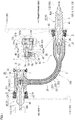
- Fig. 1 is a schematic configuration diagram showing a connection structure for a solid insulation bus including a waterproof structure for the solid insulation bus in accordance with an embodiment.
- an object of the present disclosure is to provide a waterproof structure for a solid insulation bus capable of preventing infiltration of water into the solid insulation bus.
- another object of the present disclosure is to provide a connection structure for a solid insulation bus capable of preventing infiltration of water into the solid insulation bus.
- the waterproof structure for the solid insulation bus and the connection structure for the solid insulation bus of the present disclosure described above can prevent infiltration of water into the solid insulation bus.
- Connection structure 100 for the solid insulation bus in accordance with the embodiment is intended to connect a gas insulated switchgear (GIS: located on the left side in Fig. 1 but not shown) and a transformer (located on the right side in Fig. 1 but not shown) serving as connection points 110 on transformation apparatuses, via a solid insulation bus 2.
- GIS gas insulated switchgear
- Transformer located on the right side in Fig. 1 but not shown
- Waterproof structure 1 for the solid insulation bus in accordance with the embodiment is intended to waterproof a connection portion between the GIS and solid insulation bus 2 and a connection portion between the transformer and solid insulation bus 2 when the GIS and the transformer are connected via solid insulation bus 2.
- a side closer to the GIS in each constituting member will be referred to as a GIS side
- a side closer to the transformer in each constituting member will be referred to as a transformer side.
- waterproof structure 1 for the solid insulation bus will be described, and then connection structure 100 for the solid insulation bus will be described.
- Waterproof structure 1 for the solid insulation bus includes solid insulation bus 2, a connector 3 of a conducting bar connected to a terminal 21 included in solid insulation bus 2, and a bushing 4 provided on the outer circumference of connector 3 of the conducting bar.
- Solid insulation bus 2 includes a conductor 20, terminal 21 connected to an end portion of conductor 20, and a coating portion 22 coated on the outer circumference of conductor 20 and terminal 21.
- Bushing 4 includes a bushing body portion 40 covering the outer circumference of connector 3 of the conducting bar, and a bushing flange 42 protruding from bushing body portion 40 outward in a radial direction thereof.
- Waterproof structure 1 for the solid insulation bus in accordance with the embodiment has a characteristic that it includes a waterproof portion 5 having a waterproof flange 50 interposed between an end surface of solid insulation bus 2 and bushing flange 42.
- Solid insulation bus 2 includes conductor 20 arranged at the center, terminal 21 connected to an end portion of conductor 20, and coating portion 22 coated on the outer circumference of conductor 20 and terminal 21.
- Coating portion 22 includes an inner semiconducting layer 221, an insulating layer 222, and an outer semiconducting layer 223 stacked in order from a conductor 20/terminal 21 side toward outside.
- Examples of conductor 20 include a rod-like conductor, and a composite conductor which is a combination of a rod-like conductor and a short twisted wire.
- Terminal 21 is constituted, for example, by attaching a sleeve provided with terminal 21 to an end portion of conductor 20 by fastening connection or the like.
- Inner semiconducting layer 221 and outer semiconducting layer 223 are made of a semiconducting rubber material such as semiconducting silicone rubber, for example.
- Insulating layer 222 is made of an insulating rubber material such as insulating silicone rubber, for example.
- Solid insulation bus 2 is a molded product obtained by molding a rubber material on the outer circumference of conductor 20 and terminal 21, using a molding die, for example.
- conductor 20 provided with terminal 21 is arranged in a first mold, and the semiconducting rubber material is injected between the first mold and conductor 20/terminal 21, to obtain a first intermediate member having inner semiconducting layer 221 on the outer circumference of conductor 20 and terminal 21.
- the first intermediate member is arranged in a second mold, and the insulating rubber material is injected between the second mold and the first intermediate member, to obtain a second intermediate member having inner semiconducting layer 221 and insulating layer 222 on the outer circumference of conductor 20 and terminal 21.
- the second intermediate member is arranged in a third mold, and the semiconducting rubber material is injected between the third mold and the second intermediate member, to obtain solid insulation bus 2 having inner semiconducting layer 221, insulating layer 222, and outer semiconducting layer 223 on the outer circumference of conductor 20 and terminal 21.
- Coating portion 22 includes a space 25 for connection connected to one end portion of bushing 4.
- Space 25 for connection is a recess formed by insulating layer 222 and outer semiconducting layer 223 of coating portion 22.
- Terminal 21 is exposed at a bottom surface of space 25 for connection.
- bushing body portion 40 having connector 3 of the conducting bar described later therein is inserted (press-fitted). Since terminal 21 is exposed at the bottom surface of space 25 for connection, terminal 21 is connected to connector 3 of the conducting bar inside space 25 for connection by inserting bushing body portion 40 into space 25 for connection.
- An inner circumferential surface of space 25 for connection is constituted of an inclined surface having a truncated cone shape tapering from an opened side toward a bottom-surface side.
- solid insulation bus 2 has a GIS-side end portion 2G and a transformer-side end portion 2T which are different in shape.
- coating portion 22 is provided along a longitudinal direction of conductor 20, and space 25 for connection is opened coaxially with an extension in the longitudinal direction of conductor 20.
- coating portion 22 has a thickness thicker than that of a central portion of solid insulation bus 2, and has an outer diameter larger than that of the central portion of solid insulation bus 2.
- GIS-side end portion 2G on the left side in Fig.
- insulating layer 222 and outer semiconducting layer 223 of coating portion 22 extend in a direction crossing (in this example, perpendicular to) the longitudinal direction of conductor 20, and space 25 for connection is opened in the direction crossing (perpendicular to) the longitudinal direction of conductor 20.
- space 26 for a back plug is opened on a side opposite to space 25 for connection, in the direction crossing (perpendicular to) the longitudinal direction of conductor 20.
- Space 26 for the back plug is a recess formed by insulating layer 222 and outer semiconducting layer 223 of coating portion 22.
- An inner circumferential surface of space 26 for the back plug is also constituted of an inclined surface having a truncated cone shape tapering from an opened side toward a bottom-surface side.
- Connector 3 of the conducting bar has one end portion connected to terminal 21 of solid insulation bus 2, and the other end portion connected to a lead conductor (not shown) of a connection point on a transformation apparatus (the GIS or the transformer).
- a transformation apparatus the GIS or the transformer.
- terminal 21 for connecting terminal 21 at transformer-side end portion 2T of solid insulation bus 2 to connector 3 of the conducting bar, terminal 21 is inserted into an insertion hole formed in a terminal 21-side end portion of connector 3 of the conducting bar to perform pressurized connection. Further, for connecting terminal 21 at GIS-side end portion 2G of solid insulation bus 2 to connector 3 of the conducting bar, a plate-like connection portion 210 is attached to terminal 21, a surface of connection portion 210 is connected to an end surface of connector 3 of the conducting bar, and they are fixed using a bolt 211. Space 26 for the back plug of solid insulation bus 2 is provided to tighten bolt 211.
- Bushing 4 includes bushing body portion 40 covering the outer circumference of connector 3 of the conducting bar, and bushing flange 42 protruding from bushing body portion 40 outward in the radial direction thereof.
- Bushing body portion 40 and bushing flange 42 are an integrally molded product.
- Bushing 4 is made of epoxy resin, for example.
- Bushing body portion 40 is a cylindrical member including an insertion hole 40h which penetrates one end portion and the other end portion in a longitudinal direction thereof, and through which connector 3 of the conducting bar is inserted.
- Connector 3 of the conducting bar is integrally molded inside bushing body portion 40. That is, bushing body portion 40 (bushing 4 including bushing flange 42) and connector 3 of the conducting bar are a molded product obtained by molding a material for constituting bushing 4 on the outer circumference of connector 3 of the conducting bar, using a molding die.
- Bushing body portion 40 includes an insertion region inserted into space 25 for connection of solid insulation bus 2.
- An outer circumferential surface of the insertion region of bushing body portion 40 extends along the inner circumferential surface of space 25 for connection, and is constituted of an inclined surface having a truncated cone shape tapering toward an end portion.
- the outer diameter of the insertion region of bushing body portion 40 is slightly larger than the inner diameter of space 25 for connection. Accordingly, when the insertion region of bushing body portion 40 is inserted (press-fitted) into space 25 for connection, the insertion region of bushing body portion 40 is fixed within space 25 for connection in a pressure contact state.
- bushing body portion 40 is different in a GIS-side bushing 4G and a transformer-side bushing 4T.
- transformer-side bushing 4T a region on a side opposite to the insertion region with bushing flange 42 being sandwiched therebetween is longer than a corresponding region in GIS-side bushing 4G, and has a plurality of collar portions on the outer circumference thereof. Creepage distance is secured by the collar portions.
- Bushing flange 42 is a plate-like member protruding outward in the radial direction of bushing body portion 40, at a position in the longitudinal direction of bushing body portion 40.
- Bushing flange 42 is provided on the entire circumference of bushing body portion 40 in a circumferential direction.
- bushing flange 42 is annularly provided.
- Bushing flange 42 protrudes such that an outer circumferential portion thereof is located more outward in a radial direction of solid insulation bus 2 than the end surface of solid insulation bus 2 (an end surface of space 25 for connection).
- bushing flange 42 protrudes such that the outer circumferential portion thereof is located more outward in a radial direction of waterproof flange 50 described later than an outer circumferential portion of waterproof flange 50.
- bushing flange 42 includes bolt holes 42a and 42b in front and rear surfaces, respectively.
- Bolt hole 42a is a recess opened on a side closer to waterproof flange 50 described later, and a bolt 54 for fixing waterproof flange 50 to bushing flange 42 is screwed therein.
- Bolt hole 42b is a recess opened on a side closer to a mounting flange 120 described later, and a bolt 124 for fixing mounting flange 120 to bushing flange 42 is screwed therein.
- Embedded electrodes 42ae and 42be are embedded in inner surfaces of bolt holes 42a and 42b, respectively.
- Waterproof-side bolt hole 42a opened on the waterproof flange 50 side is located more outward in a radial direction of bushing flange 42 than mounting-side bolt hole 42b opened on the mounting flange 120 side.
- tip end portions of bolt holes 42a and 42b overlap.
- Bolt holes 42a and 42b are respectively provided in bushing flange 42 uniformly in the circumferential direction.
- Bolt holes 42a and 42b may be provided at positions deviated from each other in the circumferential direction, due to restrictions on the size of bolt holes 42a and 42b, the size such as thickness of bushing flange 42, and the like.
- Waterproof portion 5 includes waterproof flange 50 interposed between the end surface of solid insulation bus 2 (end surface of space 25 for connection) and bushing flange 42.
- waterproof portion 5 includes a seal member 52 which seals between waterproof flange 50 and bushing flange 42, and a seal groove 51 formed in a bushing flange 42-side surface of waterproof flange 50.
- Waterproof flange 50 is an annular member.
- waterproof flange 50 is an annular member located on the outer circumference of bushing body portion 40 when waterproof flange 50 is attached to bushing flange 42, and having an inner circumferential surface which forms a space region (a space region 8b shown in Fig. 1 is a part thereof) between the inner circumferential surface and an outer circumferential surface of bushing body portion 40.
- Waterproof flange 50 has an outer circumferential portion located more inward in the radial direction of bushing flange 42 than the outer circumferential portion of bushing flange 42.
- Waterproof flange 50 is made of brass (a Cu-Zn alloy), for example.
- Waterproof flange 50 includes recessed seal groove 51 formed in the bushing flange 42-side surface. Seal groove 51 is annularly formed along the outer shape of waterproof flange 50. Seal member 52 is fitted into seal groove 51. Seal member 52 is an O ring made of nitrile rubber, for example. The width and the depth of seal groove 51 can be selected as appropriate as long as they allow seal member 52 to be fitted into seal groove 51 and to seal between waterproof flange 50 and bushing flange 42.
- Waterproof flange 50 includes a through hole 53 which penetrates front and rear surfaces.
- Bolt 54 for fixing waterproof flange 50 to bushing flange 42 penetrates through hole 53.
- Through hole 53 is located more outward in the radial direction of waterproof flange 50 than seal groove 51.
- the bushing flange 42-side surface of waterproof flange 50 is entirely in contact with a surface of bushing flange 42.
- an inward side thereof is in contact with the end surface of solid insulation bus 2 (end surface of space 25 for connection), and an outward side thereof is not in contact with the end surface of solid insulation bus 2 (end surface of space 25 for connection) and is exposed to the outside.
- through hole 53 is located more outward in the radial direction of waterproof flange 50 than seal groove 51, waterproof flange 50 is easily fixed to bushing flange 42 using bolt 54, and the head of bolt 54 can be prevented from interfering with contact between waterproof flange 50 and the end surface of solid insulation bus 2.
- Waterproof flange 50 is fixed to bushing flange 42 using bolt 54, and is fixed to solid insulation bus 2 by pressure contact. Specifically, waterproof flange 50 is fixed to bushing flange 42 by causing bolt 54 to penetrate through hole 53 in waterproof flange 50, and screwing bolt 54 into bolt hole 42a in bushing flange 42. In bushing 4 having bushing flange 42 to which waterproof flange 50 is fixed, by inserting (press-fitting) the insertion region of bushing body portion 40 into space 25 for connection, the insertion region of bushing body portion 40 is fixed within space 25 for connection in a pressure contact state, and waterproof flange 50 is fixed to the end surface of solid insulation bus 2 (end surface of space 25 for connection) in a pressure contact state.
- the region formed between the inner circumferential surface of waterproof flange 50 and the outer circumferential surface of bushing body portion 40 includes a press-fit region 8a which coating portion 22 enters, and space region 8b which coating portion 22 does not enter.
- coating portion 22 enters the region formed between the inner circumferential surface of waterproof flange 50 and the outer circumferential surface of bushing body portion 40 is that, when the insertion region of bushing body portion 40 is inserted into space 25 for connection, a part of a material for constituting coating portion 22 is elastically deformed during the insertion, because the outer diameter of the insertion region of bushing body portion 40 is slightly larger than the inner diameter of space 25 for connection. Due to the elastic deformation of coating portion 22, waterproof flange 50 is fixed to the end surface of solid insulation bus 2 (end surface of space 25 for connection) in a pressure contact state.
- sealing flange 6 having an insulating plug 7 is attached.
- Insulating plug 7 is made of epoxy resin, for example, and sealing flange 6 is made of brass, for example.
- Insulating plug 7 has an outer circumferential surface which extends along the inner circumferential surface of space 26 for the back plug, and which is constituted of an inclined surface having a truncated cone shape tapering from one end toward the other end.
- the outer diameter of insulating plug 7 is slightly larger than the inner diameter of space 26 for the back plug. Accordingly, when insulating plug 7 is inserted (press-fitted) into space 26 for the back plug, insulating plug 7 is fixed within space 26 for the back plug in a pressure contact state.
- embedded electrodes 71 and 72 are embedded in the vicinity of bolt 211 which connects connection portion 210 attached to terminal 21 to connector 3 of the conducting bar, and in the vicinity of a fixture to sealing flange 6.
- a waterproof flange 55 is interposed between sealing flange 6 and the end surface of solid insulation bus 2 (an end surface of space 26 for the back plug).
- Waterproof flange 55 has the same configuration as that of waterproof flange 50 interposed between the end surface of solid insulation bus 2 (end surface of space 25 for connection) and bushing flange 42.
- Connection structure 100 for the solid insulation bus is intended to connect the GIS and the transformer via solid insulation bus 2, and includes waterproof structure 1 for the solid insulation bus described above, connection point 110 on the transformation apparatus (the GIS or the transformer) connected to solid insulation bus 2 via connector 3 of the conducting bar, and mounting flange 120.
- Connection point 110 on the transformation apparatus is the GIS or the transformer, and includes a connection target 112 (such as a lead conductor) connected to solid insulation bus 2 via connector 3 of the conducting bar, and a case 114 which accommodates connection target 112.
- connection target 112 such as a lead conductor
- case 114 which accommodates connection target 112.
- the region of bushing body portion 40 on the side opposite to the insertion region with bushing flange 42 being sandwiched therebetween is accommodated within case 114, and connector 3 of the conducting bar is connected to connection target 112 within case 114.
- Mounting flange 120 is interposed between a surface of bushing flange 42 facing the connection point on the transformation apparatus and case 114 of the connection point on the transformation apparatus.
- Mounting flange 120 is an annular member.
- Mounting flange 120 has an outer circumferential portion located more outward in the radial direction of bushing flange 42 than the outer circumferential portion of bushing flange 42.
- Mounting flange 120 is made of brass, for example.
- Mounting flange 120 includes a recessed seal groove 121a formed in a bushing flange 42-side surface, and a recessed seal groove 121b formed in a surface facing the connection point on the transformation apparatus.
- Seal grooves 121a and 121b are provided at positions overlapping in a thickness direction of mounting flange 120, and are annularly formed along the outer shape of bushing flange 42.
- a seal member 122a which seals between mounting flange 120 and bushing flange 42 is fitted into seal groove 121a
- a seal member 122b which seals between mounting flange 120 and the connection point on the transformation apparatus (case 114) is fitted into seal groove 121b.
- Seal members 122a and 122b are each an O ring made of nitrile rubber, for example.
- Mounting flange 120 includes a through hole 123 which penetrates front and rear surfaces.
- Bolt 124 for fixing mounting flange 120 to bushing flange 42 penetrates through hole 123.
- Through hole 123 is formed such that, in a state where mounting flange 120 is fixed to bushing flange 42, the head of bolt 124 is located more inward than the surface of mounting flange 120. Accordingly, in the state where mounting flange 120 is fixed to bushing flange 42, the surface of mounting flange 120 is entirely in contact with an outer surface of case 114.
- through hole 123 is located more inward in a radial direction of mounting flange 120 than seal grooves 121a and 121b.
- waterproof flange 50 of waterproof portion 5 can prevent water from infiltrating into solid insulation bus 2 from between the end surface of solid insulation bus 2 (end surface of space 25 for connection) and bushing flange 42.
- waterproof flange 50 can also prevent water from infiltrating into solid insulation bus 2 from between the end surface of the space formed in coating portion 22 (end surface of space 26 for the back plug) and sealing flange 6.
- waterproof structure 1 for the solid insulation bus can be used even under an environment where it is exposed to rain water, such as outdoors.
- waterproof structure 1 for the solid insulation bus is intended for use at a high voltage such as 66 kV or more, it can exhibit a high waterproof effect.
- connection structure 100 for the solid insulation bus can be constructed under an outdoor environment where it may be exposed to rain water.
- waterproof flange 50 has the outer circumferential portion located more inward in the radial direction of bushing flange 42 than the outer circumferential portion of bushing flange 42, water splashing on bushing flange 42 can be guided toward waterproof flange 50.
- bushing flange 42 has the outer circumferential portion located more inward in the radial direction of mounting flange 120 than the outer circumferential portion of mounting flange 120, water splashing on mounting flange 120 can be guided toward waterproof flange 50 via bushing flange 42. Since waterproof flange 50 can provide waterproofing and a water droplet is less likely to remain around waterproof flange 50, waterproof portion 5 easily exhibits the waterproof effect.
- Waterproof flange 50 and mounting flange 120 are fixed to bushing flange 42 using bolts 54 and 124, respectively, and bolt holes 42a and 42b into which bolts 54 and 124 are screwed, respectively, are formed in the front and rear surfaces of bushing flange 42. Since bolt hole 42a on the waterproof flange 50 side is located more outward than bolt hole 42b on the mounting flange 120 side, bolt 54 can be arranged more outward than seal member 52, waterproof flange 50 is easily fixed to bushing flange 42, pressure contact can be established between waterproof flange 50 and the end surface of solid insulation bus 2, and sealing property between waterproof flange 50 and bushing flange 42 can be effectively secured.
- seal member 52 can be arranged on a surface on a side opposite to bolt hole 42b, and seal member 122a can be arranged on a surface on a side opposite to bolt hole 42a, an increase in the size of bushing flange 42 in a thickness direction can be suppressed, and sealing property between the members can be effectively secured.
Landscapes
- Engineering & Computer Science (AREA)
- Power Engineering (AREA)
- Connector Housings Or Holding Contact Members (AREA)
- Insulated Conductors (AREA)
- Cable Accessories (AREA)
Abstract
Description
- The present invention relates to a waterproof structure for a solid insulation bus and a connection structure for a solid insulation bus.
- The present application claims priority based on Japanese Patent Application No.
2017-096863 filed on May 15, 2017 -
PTL 1 discloses an insulator covered bus of an electrical connector, including a bus having a rod-like conductor and a short twisted wire connected in combination, terminal fittings connected to both ends of the bus, and an inner semiconducting layer, an insulating layer, and an outer semiconducting layer molded on the bus and the terminal fittings. This insulator covered bus of the electrical connector is attached to connect power apparatuses. - PTL 1: Japanese Patent Laying-Open No.
10-233244 - A waterproof structure for a solid insulation bus in accordance with the present disclosure includes: a solid insulation bus having a conductor, a terminal connected to an end portion of the conductor, and a coating portion including an inner semiconducting layer, an insulating layer, and an outer semiconducting layer stacked in order from a conductor/terminal side toward outside; a connector of a conducting bar connected to the terminal; a bushing having a bushing body portion covering outer circumference of the connector of the conducting bar, and a bushing flange protruding from the bushing body portion outward in a radial direction thereof; and a waterproof portion having a waterproof flange interposed between an end surface of the solid insulation bus and the bushing flange.
- A connection structure for a solid insulation bus in accordance with the present disclosure includes: the waterproof structure for the solid insulation bus in accordance with the present disclosure; a connection point on a transformation apparatus connected to the solid insulation bus via the connector of the conducting bar; and a mounting flange interposed between a surface of the bushing flange facing the connection point on the transformation apparatus and the connection point on the transformation apparatus.
-
Fig. 1 is a schematic configuration diagram showing a connection structure for a solid insulation bus including a waterproof structure for the solid insulation bus in accordance with an embodiment. - Countermeasures for preventing water from infiltrating into an insulator covered bus of an electrical connector (solid insulation bus) when it is used outdoors are desired. However, waterproofing is not considered in
PTL 1. - Thus, an object of the present disclosure is to provide a waterproof structure for a solid insulation bus capable of preventing infiltration of water into the solid insulation bus. In addition, another object of the present disclosure is to provide a connection structure for a solid insulation bus capable of preventing infiltration of water into the solid insulation bus.
- The waterproof structure for the solid insulation bus and the connection structure for the solid insulation bus of the present disclosure described above can prevent infiltration of water into the solid insulation bus.
- First, the content of an embodiment of the present invention will be described in list form.
- (1) A waterproof structure for a solid insulation bus in accordance with the embodiment of the present invention includes a solid insulation bus having a conductor, a terminal connected to an end portion of the conductor, and a coating portion including an inner semiconducting layer, an insulating layer, and an outer semiconducting layer stacked in order from a conductor/terminal side toward outside; a connector of a conducting bar connected to the terminal; a bushing having a bushing body portion covering outer circumference of the connector of the conducting bar, and a bushing flange protruding from the bushing body portion outward in a radial direction thereof; and a waterproof portion having a waterproof flange interposed between an end surface of the solid insulation bus and the bushing flange.
With the above configuration, the waterproof flange can prevent water from infiltrating into the solid insulation bus from between the end surface of the solid insulation bus and the bushing flange. Accordingly, the waterproof structure for the solid insulation bus is a structure necessary for use under an outdoor environment where it may be exposed to rain water. - (2) As one aspect of the waterproof structure for the solid insulation bus, the waterproof portion includes a seal member which seals between the waterproof flange and the bushing flange, and a seal groove which is formed in a bushing flange-side surface of the waterproof flange, and into which the seal member is fitted.
By including the seal member as the waterproof portion, the waterproof structure for the solid insulation bus can have an improved waterproof effect. - (3) As one aspect of the waterproof structure for the solid insulation bus, an outer circumferential portion of the bushing flange is located more outward in a radial direction of the waterproof flange than an outer circumferential portion of the waterproof flange.
With the above configuration, when water splashes on the bushing flange, a water droplet thereof is easily guided toward the waterproof flange. Since the waterproof flange can prevent water from infiltrating into the solid insulation bus, and a water droplet is less likely to remain around the waterproof flange, the waterproof portion easily exhibits the waterproof effect. - (4) As one aspect of the waterproof structure for the solid insulation bus, the bushing body portion includes an insertion region inserted into the solid insulation bus, and a region formed between an inner circumferential surface of the waterproof flange and an outer circumferential surface of the bushing body portion includes a press-fit region which the coating portion enters, and a space region which the coating portion does not enter.
The reason why the coating portion enters the region formed between the inner circumferential surface of the waterproof flange and the outer circumferential surface of the bushing body portion is that, when the insertion region of the bushing body portion is inserted (press-fitted) into the solid insulation bus, a part of a material for constituting the coating portion is elastically deformed. Due to the elastic deformation of the coating portion, the waterproof flange is more firmly fixed to the end surface of the solid insulation bus, and thus the waterproof structure for the solid insulation bus can have an improved waterproof effect. - (5) A connection structure for a solid insulation bus in accordance with the embodiment of the present invention includes: the waterproof structure for the solid insulation bus according to any one of (1) to (4) described above; a connection point on a transformation apparatus connected to the solid insulation bus via the connector of the conducting bar; and a mounting flange interposed between a surface of the bushing flange facing the connection point on the transformation apparatus and the connection point on a transformation apparatus.
By including the waterproof structure for the solid insulation bus described above, waterproofing can be provided at each end portion of the solid insulation bus when power apparatuses are connected via the solid insulation bus, and thus the connection structure can be constructed under the outdoor environment where it may be exposed to rain water. - (6) As one aspect of the connection structure for the solid insulation bus, the bushing flange includes a waterproof-side bolt hole opened on a waterproof flange side, and a mounting-side bolt hole opened on a mounting flange side, and the waterproof-side bolt hole is located more outward in a radial direction of the bushing flange than the mounting-side bolt hole.
Since the waterproof-side bolt hole is located more outward in the radial direction of the bushing flange than the mounting-side bolt hole, a bolt for fixing the waterproof flange to the bushing flange can be provided outward in the radial direction of the waterproof flange. Thereby, the waterproof flange is easily fixed to the bushing flange, and close contact can be established between the waterproof flange and the end surface of the solid insulation bus. Thus, sealing property between the waterproof flange and the solid insulation bus can be secured. - (7) As one aspect of the connection structure for the solid insulation bus, the outer circumferential portion of the bushing flange is located more outward in the radial direction of the waterproof flange than the outer circumferential portion of the waterproof flange, and is located more inward in the radial direction of the waterproof flange than an outer circumferential portion of the mounting flange.
- When water splashes on the mounting flange, a water droplet thereof is easily guided toward the waterproof flange via the bushing flange. Since the waterproof flange can prevent water from infiltrating into the solid insulation bus, the water droplet guided to the waterproof flange flows down from the solid insulation bus.
- Hereinafter, the embodiment of the present invention will be specifically described with reference to the drawing. It should be noted that the present invention is not limited to these examples, and is defined by the scope of the claims and is intended to include any modifications within the scope and meaning equivalent to the scope of the claims.
- Referring to
Fig. 1 , awaterproof structure 1 for a solid insulation bus and aconnection structure 100 for the solid insulation bus in accordance with the embodiment will be described.Connection structure 100 for the solid insulation bus in accordance with the embodiment is intended to connect a gas insulated switchgear (GIS: located on the left side inFig. 1 but not shown) and a transformer (located on the right side inFig. 1 but not shown) serving asconnection points 110 on transformation apparatuses, via asolid insulation bus 2.Waterproof structure 1 for the solid insulation bus in accordance with the embodiment is intended to waterproof a connection portion between the GIS andsolid insulation bus 2 and a connection portion between the transformer andsolid insulation bus 2 when the GIS and the transformer are connected viasolid insulation bus 2. In the description below, a side closer to the GIS in each constituting member will be referred to as a GIS side, and a side closer to the transformer in each constituting member will be referred to as a transformer side. In the following,waterproof structure 1 for the solid insulation bus will be described, and thenconnection structure 100 for the solid insulation bus will be described. -
Waterproof structure 1 for the solid insulation bus includessolid insulation bus 2, aconnector 3 of a conducting bar connected to aterminal 21 included insolid insulation bus 2, and abushing 4 provided on the outer circumference ofconnector 3 of the conducting bar.Solid insulation bus 2 includes aconductor 20,terminal 21 connected to an end portion ofconductor 20, and acoating portion 22 coated on the outer circumference ofconductor 20 andterminal 21.Bushing 4 includes abushing body portion 40 covering the outer circumference ofconnector 3 of the conducting bar, and a bushingflange 42 protruding frombushing body portion 40 outward in a radial direction thereof.Waterproof structure 1 for the solid insulation bus in accordance with the embodiment has a characteristic that it includes awaterproof portion 5 having awaterproof flange 50 interposed between an end surface ofsolid insulation bus 2 and bushingflange 42. -
Solid insulation bus 2 includesconductor 20 arranged at the center,terminal 21 connected to an end portion ofconductor 20, andcoating portion 22 coated on the outer circumference ofconductor 20 andterminal 21. Coatingportion 22 includes an innersemiconducting layer 221, aninsulating layer 222, and an outersemiconducting layer 223 stacked in order from aconductor 20/terminal 21 side toward outside. - Examples of
conductor 20 include a rod-like conductor, and a composite conductor which is a combination of a rod-like conductor and a short twisted wire.Terminal 21 is constituted, for example, by attaching a sleeve provided withterminal 21 to an end portion ofconductor 20 by fastening connection or the like. - Inner
semiconducting layer 221 and outersemiconducting layer 223 are made of a semiconducting rubber material such as semiconducting silicone rubber, for example. Insulatinglayer 222 is made of an insulating rubber material such as insulating silicone rubber, for example. -
Solid insulation bus 2 is a molded product obtained by molding a rubber material on the outer circumference ofconductor 20 andterminal 21, using a molding die, for example. Specifically,conductor 20 provided withterminal 21 is arranged in a first mold, and the semiconducting rubber material is injected between the first mold andconductor 20/terminal 21, to obtain a first intermediate member havinginner semiconducting layer 221 on the outer circumference ofconductor 20 andterminal 21. Then, the first intermediate member is arranged in a second mold, and the insulating rubber material is injected between the second mold and the first intermediate member, to obtain a second intermediate member having innersemiconducting layer 221 and insulatinglayer 222 on the outer circumference ofconductor 20 andterminal 21. Finally, the second intermediate member is arranged in a third mold, and the semiconducting rubber material is injected between the third mold and the second intermediate member, to obtainsolid insulation bus 2 having innersemiconducting layer 221, insulatinglayer 222, and outersemiconducting layer 223 on the outer circumference ofconductor 20 andterminal 21. -
Coating portion 22 includes aspace 25 for connection connected to one end portion ofbushing 4.Space 25 for connection is a recess formed by insulatinglayer 222 and outersemiconducting layer 223 ofcoating portion 22.Terminal 21 is exposed at a bottom surface ofspace 25 for connection. Into thisspace 25 for connection,bushing body portion 40 havingconnector 3 of the conducting bar described later therein is inserted (press-fitted). Sinceterminal 21 is exposed at the bottom surface ofspace 25 for connection, terminal 21 is connected toconnector 3 of the conducting bar insidespace 25 for connection by insertingbushing body portion 40 intospace 25 for connection. An inner circumferential surface ofspace 25 for connection is constituted of an inclined surface having a truncated cone shape tapering from an opened side toward a bottom-surface side. - In this example,
solid insulation bus 2 has a GIS-side end portion 2G and a transformer-side end portion 2T which are different in shape. In transformer-side end portion 2T (on the right side inFig. 1 ),coating portion 22 is provided along a longitudinal direction ofconductor 20, andspace 25 for connection is opened coaxially with an extension in the longitudinal direction ofconductor 20. In transformer-side end portion 2T, coatingportion 22 has a thickness thicker than that of a central portion ofsolid insulation bus 2, and has an outer diameter larger than that of the central portion ofsolid insulation bus 2. On the other hand, in GIS-side end portion 2G (on the left side inFig. 1 ), insulatinglayer 222 and outersemiconducting layer 223 ofcoating portion 22 extend in a direction crossing (in this example, perpendicular to) the longitudinal direction ofconductor 20, andspace 25 for connection is opened in the direction crossing (perpendicular to) the longitudinal direction ofconductor 20. Further, in GIS-side end portion 2G, aspace 26 for a back plug is opened on a side opposite tospace 25 for connection, in the direction crossing (perpendicular to) the longitudinal direction ofconductor 20.Space 26 for the back plug is a recess formed by insulatinglayer 222 and outersemiconducting layer 223 ofcoating portion 22. An inner circumferential surface ofspace 26 for the back plug is also constituted of an inclined surface having a truncated cone shape tapering from an opened side toward a bottom-surface side. -
Connector 3 of the conducting bar has one end portion connected toterminal 21 ofsolid insulation bus 2, and the other end portion connected to a lead conductor (not shown) of a connection point on a transformation apparatus (the GIS or the transformer). By electrically connectingterminal 21 to the lead conductor of the connection point on the transformation apparatus viaconnector 3 of the conducting bar at each of GIS-side end portion 2G and transformer-side end portion 2T ofsolid insulation bus 2, the GIS and the transformer are electrically connected viasolid insulation bus 2. - In this example, for connecting
terminal 21 at transformer-side end portion 2T ofsolid insulation bus 2 toconnector 3 of the conducting bar, terminal 21 is inserted into an insertion hole formed in a terminal 21-side end portion ofconnector 3 of the conducting bar to perform pressurized connection. Further, for connectingterminal 21 at GIS-side end portion 2G ofsolid insulation bus 2 toconnector 3 of the conducting bar, a plate-like connection portion 210 is attached toterminal 21, a surface ofconnection portion 210 is connected to an end surface ofconnector 3 of the conducting bar, and they are fixed using abolt 211.Space 26 for the back plug ofsolid insulation bus 2 is provided to tightenbolt 211. -
Bushing 4 includesbushing body portion 40 covering the outer circumference ofconnector 3 of the conducting bar, andbushing flange 42 protruding frombushing body portion 40 outward in the radial direction thereof. Bushingbody portion 40 andbushing flange 42 are an integrally molded product.Bushing 4 is made of epoxy resin, for example. - Bushing
body portion 40 is a cylindrical member including aninsertion hole 40h which penetrates one end portion and the other end portion in a longitudinal direction thereof, and through whichconnector 3 of the conducting bar is inserted.Connector 3 of the conducting bar is integrally molded insidebushing body portion 40. That is, bushing body portion 40 (bushing 4 including bushing flange 42) andconnector 3 of the conducting bar are a molded product obtained by molding a material for constitutingbushing 4 on the outer circumference ofconnector 3 of the conducting bar, using a molding die. - Bushing
body portion 40 includes an insertion region inserted intospace 25 for connection ofsolid insulation bus 2. An outer circumferential surface of the insertion region ofbushing body portion 40 extends along the inner circumferential surface ofspace 25 for connection, and is constituted of an inclined surface having a truncated cone shape tapering toward an end portion. The outer diameter of the insertion region ofbushing body portion 40 is slightly larger than the inner diameter ofspace 25 for connection. Accordingly, when the insertion region ofbushing body portion 40 is inserted (press-fitted) intospace 25 for connection, the insertion region ofbushing body portion 40 is fixed withinspace 25 for connection in a pressure contact state. - In this example, the shape of
bushing body portion 40 is different in a GIS-side bushing 4G and a transformer-side bushing 4T. In transformer-side bushing 4T, a region on a side opposite to the insertion region withbushing flange 42 being sandwiched therebetween is longer than a corresponding region in GIS-side bushing 4G, and has a plurality of collar portions on the outer circumference thereof. Creepage distance is secured by the collar portions. -
Bushing flange 42 is a plate-like member protruding outward in the radial direction ofbushing body portion 40, at a position in the longitudinal direction ofbushing body portion 40.Bushing flange 42 is provided on the entire circumference ofbushing body portion 40 in a circumferential direction. In this example,bushing flange 42 is annularly provided.Bushing flange 42 protrudes such that an outer circumferential portion thereof is located more outward in a radial direction ofsolid insulation bus 2 than the end surface of solid insulation bus 2 (an end surface ofspace 25 for connection). In addition,bushing flange 42 protrudes such that the outer circumferential portion thereof is located more outward in a radial direction ofwaterproof flange 50 described later than an outer circumferential portion ofwaterproof flange 50. - As shown in an enlarged view in
Fig. 1 ,bushing flange 42 includesbolt holes 42a and 42b in front and rear surfaces, respectively. Bolt hole 42a is a recess opened on a side closer towaterproof flange 50 described later, and abolt 54 for fixingwaterproof flange 50 tobushing flange 42 is screwed therein.Bolt hole 42b is a recess opened on a side closer to a mountingflange 120 described later, and abolt 124 for fixing mountingflange 120 tobushing flange 42 is screwed therein. Embedded electrodes 42ae and 42be are embedded in inner surfaces ofbolt holes 42a and 42b, respectively. Waterproof-side bolt hole 42a opened on thewaterproof flange 50 side is located more outward in a radial direction ofbushing flange 42 than mounting-side bolt hole 42b opened on the mountingflange 120 side. In addition, when waterproof-side bolt hole 42a and mounting-side bolt hole 42b are seen through in a circumferential direction ofbushing flange 42, tip end portions ofbolt holes 42a and 42b overlap.Bolt holes 42a and 42b are respectively provided inbushing flange 42 uniformly in the circumferential direction.Bolt holes 42a and 42b may be provided at positions deviated from each other in the circumferential direction, due to restrictions on the size ofbolt holes 42a and 42b, the size such as thickness ofbushing flange 42, and the like. -
Waterproof portion 5 includeswaterproof flange 50 interposed between the end surface of solid insulation bus 2 (end surface ofspace 25 for connection) andbushing flange 42. In addition,waterproof portion 5 includes aseal member 52 which seals betweenwaterproof flange 50 andbushing flange 42, and aseal groove 51 formed in a bushing flange 42-side surface ofwaterproof flange 50. -
Waterproof flange 50 is an annular member. In this example,waterproof flange 50 is an annular member located on the outer circumference ofbushing body portion 40 whenwaterproof flange 50 is attached tobushing flange 42, and having an inner circumferential surface which forms a space region (aspace region 8b shown inFig. 1 is a part thereof) between the inner circumferential surface and an outer circumferential surface ofbushing body portion 40.Waterproof flange 50 has an outer circumferential portion located more inward in the radial direction ofbushing flange 42 than the outer circumferential portion ofbushing flange 42.Waterproof flange 50 is made of brass (a Cu-Zn alloy), for example. -
Waterproof flange 50 includes recessedseal groove 51 formed in the bushing flange 42-side surface.Seal groove 51 is annularly formed along the outer shape ofwaterproof flange 50.Seal member 52 is fitted intoseal groove 51.Seal member 52 is an O ring made of nitrile rubber, for example. The width and the depth ofseal groove 51 can be selected as appropriate as long as they allowseal member 52 to be fitted intoseal groove 51 and to seal betweenwaterproof flange 50 andbushing flange 42. -
Waterproof flange 50 includes a throughhole 53 which penetrates front and rear surfaces.Bolt 54 for fixingwaterproof flange 50 tobushing flange 42 penetrates throughhole 53. Throughhole 53 is located more outward in the radial direction ofwaterproof flange 50 thanseal groove 51. The bushing flange 42-side surface ofwaterproof flange 50 is entirely in contact with a surface ofbushing flange 42. On the other hand, in a solid insulation bus 2 (space 25 for connection)-side surface ofwaterproof flange 50, an inward side thereof is in contact with the end surface of solid insulation bus 2 (end surface ofspace 25 for connection), and an outward side thereof is not in contact with the end surface of solid insulation bus 2 (end surface ofspace 25 for connection) and is exposed to the outside. Since throughhole 53 is located more outward in the radial direction ofwaterproof flange 50 thanseal groove 51,waterproof flange 50 is easily fixed tobushing flange 42 usingbolt 54, and the head ofbolt 54 can be prevented from interfering with contact betweenwaterproof flange 50 and the end surface ofsolid insulation bus 2. -
Waterproof flange 50 is fixed tobushing flange 42 usingbolt 54, and is fixed tosolid insulation bus 2 by pressure contact. Specifically,waterproof flange 50 is fixed tobushing flange 42 by causingbolt 54 to penetrate throughhole 53 inwaterproof flange 50, and screwingbolt 54 into bolt hole 42a inbushing flange 42. Inbushing 4 havingbushing flange 42 to whichwaterproof flange 50 is fixed, by inserting (press-fitting) the insertion region ofbushing body portion 40 intospace 25 for connection, the insertion region ofbushing body portion 40 is fixed withinspace 25 for connection in a pressure contact state, andwaterproof flange 50 is fixed to the end surface of solid insulation bus 2 (end surface ofspace 25 for connection) in a pressure contact state. - In a state where
waterproof flange 50 is fixed between the end surface of solid insulation bus 2 (end surface ofspace 25 for connection) andbushing flange 42, the region formed between the inner circumferential surface ofwaterproof flange 50 and the outer circumferential surface ofbushing body portion 40 includes a press-fit region 8a whichcoating portion 22 enters, andspace region 8b whichcoating portion 22 does not enter. The reason why coatingportion 22 enters the region formed between the inner circumferential surface ofwaterproof flange 50 and the outer circumferential surface ofbushing body portion 40 is that, when the insertion region ofbushing body portion 40 is inserted intospace 25 for connection, a part of a material for constitutingcoating portion 22 is elastically deformed during the insertion, because the outer diameter of the insertion region ofbushing body portion 40 is slightly larger than the inner diameter ofspace 25 for connection. Due to the elastic deformation ofcoating portion 22,waterproof flange 50 is fixed to the end surface of solid insulation bus 2 (end surface ofspace 25 for connection) in a pressure contact state. - To
space 26 for the back plug formed in GIS-side end portion 2G ofsolid insulation bus 2, a sealingflange 6 having an insulating plug 7 is attached. Insulating plug 7 is made of epoxy resin, for example, and sealingflange 6 is made of brass, for example. - Insulating plug 7 has an outer circumferential surface which extends along the inner circumferential surface of
space 26 for the back plug, and which is constituted of an inclined surface having a truncated cone shape tapering from one end toward the other end. The outer diameter of insulating plug 7 is slightly larger than the inner diameter ofspace 26 for the back plug. Accordingly, when insulating plug 7 is inserted (press-fitted) intospace 26 for the back plug, insulating plug 7 is fixed withinspace 26 for the back plug in a pressure contact state. In insulating plug 7, embeddedelectrodes bolt 211 which connectsconnection portion 210 attached toterminal 21 toconnector 3 of the conducting bar, and in the vicinity of a fixture to sealingflange 6. - A
waterproof flange 55 is interposed between sealingflange 6 and the end surface of solid insulation bus 2 (an end surface ofspace 26 for the back plug).Waterproof flange 55 has the same configuration as that ofwaterproof flange 50 interposed between the end surface of solid insulation bus 2 (end surface ofspace 25 for connection) andbushing flange 42. -
Connection structure 100 for the solid insulation bus is intended to connect the GIS and the transformer viasolid insulation bus 2, and includeswaterproof structure 1 for the solid insulation bus described above,connection point 110 on the transformation apparatus (the GIS or the transformer) connected tosolid insulation bus 2 viaconnector 3 of the conducting bar, and mountingflange 120. -
Connection point 110 on the transformation apparatus is the GIS or the transformer, and includes a connection target 112 (such as a lead conductor) connected tosolid insulation bus 2 viaconnector 3 of the conducting bar, and acase 114 which accommodatesconnection target 112. The region ofbushing body portion 40 on the side opposite to the insertion region withbushing flange 42 being sandwiched therebetween is accommodated withincase 114, andconnector 3 of the conducting bar is connected toconnection target 112 withincase 114. - Mounting
flange 120 is interposed between a surface ofbushing flange 42 facing the connection point on the transformation apparatus andcase 114 of the connection point on the transformation apparatus. Mountingflange 120 is an annular member. Mountingflange 120 has an outer circumferential portion located more outward in the radial direction ofbushing flange 42 than the outer circumferential portion ofbushing flange 42. Mountingflange 120 is made of brass, for example. - Mounting
flange 120 includes a recessedseal groove 121a formed in a bushing flange 42-side surface, and a recessedseal groove 121b formed in a surface facing the connection point on the transformation apparatus.Seal grooves flange 120, and are annularly formed along the outer shape ofbushing flange 42. Aseal member 122a which seals between mountingflange 120 andbushing flange 42 is fitted intoseal groove 121a, and aseal member 122b which seals between mountingflange 120 and the connection point on the transformation apparatus (case 114) is fitted intoseal groove 121b.Seal members - Mounting
flange 120 includes a throughhole 123 which penetrates front and rear surfaces.Bolt 124 for fixing mountingflange 120 tobushing flange 42 penetrates throughhole 123. Throughhole 123 is formed such that, in a state where mountingflange 120 is fixed tobushing flange 42, the head ofbolt 124 is located more inward than the surface of mountingflange 120. Accordingly, in the state where mountingflange 120 is fixed tobushing flange 42, the surface of mountingflange 120 is entirely in contact with an outer surface ofcase 114. In addition, throughhole 123 is located more inward in a radial direction of mountingflange 120 thanseal grooves - In
waterproof structure 1 for the solid insulation bus described above,waterproof flange 50 ofwaterproof portion 5 can prevent water from infiltrating intosolid insulation bus 2 from between the end surface of solid insulation bus 2 (end surface ofspace 25 for connection) andbushing flange 42. In addition,waterproof flange 50 can also prevent water from infiltrating intosolid insulation bus 2 from between the end surface of the space formed in coating portion 22 (end surface ofspace 26 for the back plug) and sealingflange 6. Accordingly,waterproof structure 1 for the solid insulation bus can be used even under an environment where it is exposed to rain water, such as outdoors. In particular, even whenwaterproof structure 1 for the solid insulation bus is intended for use at a high voltage such as 66 kV or more, it can exhibit a high waterproof effect. Accordingly, by includingwaterproof structure 1 for the solid insulation bus,connection structure 100 for the solid insulation bus can be constructed under an outdoor environment where it may be exposed to rain water. - Since
waterproof flange 50 has the outer circumferential portion located more inward in the radial direction ofbushing flange 42 than the outer circumferential portion ofbushing flange 42, water splashing onbushing flange 42 can be guided towardwaterproof flange 50. In addition, since bushingflange 42 has the outer circumferential portion located more inward in the radial direction of mountingflange 120 than the outer circumferential portion of mountingflange 120, water splashing on mountingflange 120 can be guided towardwaterproof flange 50 viabushing flange 42. Sincewaterproof flange 50 can provide waterproofing and a water droplet is less likely to remain aroundwaterproof flange 50,waterproof portion 5 easily exhibits the waterproof effect. -
Waterproof flange 50 and mountingflange 120 are fixed tobushing flange 42 usingbolts holes 42a and 42b into whichbolts bushing flange 42. Since bolt hole 42a on thewaterproof flange 50 side is located more outward thanbolt hole 42b on the mountingflange 120 side, bolt 54 can be arranged more outward thanseal member 52,waterproof flange 50 is easily fixed tobushing flange 42, pressure contact can be established betweenwaterproof flange 50 and the end surface ofsolid insulation bus 2, and sealing property betweenwaterproof flange 50 andbushing flange 42 can be effectively secured. In addition, sinceseal member 52 can be arranged on a surface on a side opposite to bolthole 42b, andseal member 122a can be arranged on a surface on a side opposite to bolt hole 42a, an increase in the size ofbushing flange 42 in a thickness direction can be suppressed, and sealing property between the members can be effectively secured. -
- 1:
- waterproof structure for solid insulation bus;
- 2:
- solid insulation bus;
- 2G:
- GIS-side end portion;
- 2T:
- transformer-side end portion;
- 20:
- conductor;
- 21:
- terminal;
- 210:
- connection portion;
- 211:
- bolt;
- 22:
- coating portion;
- 221:
- inner semiconducting layer;
- 222:
- insulating layer;
- 223:
- outer semiconducting layer;
- 25:
- space for connection;
- 26:
- space for a back plug;
- 3:
- connector of a conducting bar;
- 4:
- bushing;
- 4G:
- GIS-side bushing;
- 4T:
- transformer-side bushing;
- 40:
- bushing body portion;
- 40h:
- insertion hole;
- 42:
- bushing flange;
- 42a, 42b:
- bolt hole;
- 42ae, 42be:
- embedded electrode;
- 5:
- waterproof portion;
- 50, 55:
- waterproof flange;
- 51:
- seal groove;
- 52:
- seal member;
- 53:
- through hole;
- 54:
- bolt;
- 6:
- sealing flange;
- 7:
- insulating plug;
- 71, 72:
- embedded electrode;
- 8a:
- press-fit region;
- 8b:
- space region;
- 100:
- connection structure for solid insulation bus;
- 110:
- connection point on a transformation apparatus;
- 112:
- connection target;
- 114:
- case;
- 120:
- mounting flange;
- 121a, 121b:
- seal groove;
- 122a, 122b:
- seal member;
- 123:
- through hole;
- 124:
- bolt.
Claims (7)
- A waterproof structure for a solid insulation bus, the waterproof structure comprising:a solid insulation bus having a conductor, a terminal connected to an end portion of the conductor, and a coating portion including an inner semiconducting layer, an insulating layer, and an outer semiconducting layer stacked in order from a conductor/terminal side toward outside;a connector of a conducting bar connected to the terminal;a bushing having a bushing body portion covering outer circumference of the connector of the conducting bar, and a bushing flange protruding from the bushing body portion outward in a radial direction thereof; anda waterproof portion having a waterproof flange interposed between an end surface of the solid insulation bus and the bushing flange.
- The waterproof structure for the solid insulation bus according to claim 1, wherein the waterproof portion includes
a seal member which seals between the waterproof flange and the bushing flange, and
a seal groove which is formed in a bushing flange-side surface of the waterproof flange, and into which the seal member is fitted. - The waterproof structure for the solid insulation bus according to claim 1 or 2, wherein an outer circumferential portion of the bushing flange is located more outward in a radial direction of the waterproof flange than an outer circumferential portion of the waterproof flange.
- The waterproof structure for the solid insulation bus according to any one of claims 1 to 3, wherein
the bushing body portion includes an insertion region inserted into the solid insulation bus, and
a region formed between an inner circumferential surface of the waterproof flange and an outer circumferential surface of the bushing body portion includes a press-fit region which the coating portion enters, and a space region which the coating portion does not enter. - A connection structure for a solid insulation bus, the connection structure comprising:the waterproof structure for the solid insulation bus according to any one of claims 1 to 4;a connection point on a transformation apparatus connected to the solid insulation bus via the connector of the conducting bar; anda mounting flange interposed between a surface of the bushing flange facing the connection point on the transformation apparatus and the connection point on the transformation apparatus.
- The connection structure for the solid insulation bus according to claim 5, wherein
the bushing flange includesa waterproof-side bolt hole opened on a waterproof flange side, anda mounting-side bolt hole opened on a mounting flange side, andthe waterproof-side bolt hole is located more outward in a radial direction of the bushing flange than the mounting-side bolt hole. - The connection structure for the solid insulation bus according to claim 5 or 6, wherein the outer circumferential portion of the bushing flange is located more outward in the radial direction of the waterproof flange than the outer circumferential portion of the waterproof flange, and is located more inward in the radial direction of the waterproof flange than an outer circumferential portion of the mounting flange.
Applications Claiming Priority (2)
| Application Number | Priority Date | Filing Date | Title |
|---|---|---|---|
| JP2017096863A JP6814092B2 (en) | 2017-05-15 | 2017-05-15 | Waterproof structure of solid insulating bus and connection structure of solid insulating bus |
| PCT/JP2018/010831 WO2018211811A1 (en) | 2017-05-15 | 2018-03-19 | Waterproof structure for solid insulation bus, and connection structure for solid insulation bus |
Publications (3)
| Publication Number | Publication Date |
|---|---|
| EP3627643A1 true EP3627643A1 (en) | 2020-03-25 |
| EP3627643A4 EP3627643A4 (en) | 2021-02-24 |
| EP3627643B1 EP3627643B1 (en) | 2025-09-10 |
Family
ID=64273847
Family Applications (1)
| Application Number | Title | Priority Date | Filing Date |
|---|---|---|---|
| EP18803044.9A Active EP3627643B1 (en) | 2017-05-15 | 2018-03-19 | Waterproof structure for solid insulation bus, and connection structure for solid insulation bus |
Country Status (4)
| Country | Link |
|---|---|
| EP (1) | EP3627643B1 (en) |
| JP (1) | JP6814092B2 (en) |
| CN (1) | CN110603698B (en) |
| WO (1) | WO2018211811A1 (en) |
Families Citing this family (3)
| Publication number | Priority date | Publication date | Assignee | Title |
|---|---|---|---|---|
| PL3981051T3 (en) * | 2019-06-07 | 2026-04-20 | Nkt Hv Cables Ab | Power cable termination system |
| CN113161877B (en) * | 2021-03-15 | 2023-03-03 | 深圳供电局有限公司 | Flange rainproof device |
| JP2024037100A (en) * | 2022-09-06 | 2024-03-18 | 住友電気工業株式会社 | Charging terminal |
Family Cites Families (13)
| Publication number | Priority date | Publication date | Assignee | Title |
|---|---|---|---|---|
| US3861777A (en) * | 1973-09-20 | 1975-01-21 | Permali Inc | Separable electrical connector |
| JPS6226129U (en) * | 1985-07-29 | 1987-02-17 | ||
| JP3004485B2 (en) * | 1992-09-11 | 2000-01-31 | 昭和電線電纜株式会社 | Bushing insulation plug and its fitting |
| FR2736461B1 (en) * | 1995-07-06 | 1997-08-08 | Gec Alsthom T & D Sa | DIELECTRICALLY WATERPROOF BUSHING |
| JPH09289049A (en) * | 1996-04-22 | 1997-11-04 | Furukawa Electric Co Ltd:The | Directly connected device |
| JPH10233244A (en) * | 1997-02-20 | 1998-09-02 | Furukawa Electric Co Ltd:The | Mold insulation contact bus |
| JP5038875B2 (en) * | 2007-12-18 | 2012-10-03 | 株式会社オートネットワーク技術研究所 | Wire bundle with connector with waterproof function |
| CN201708450U (en) * | 2010-06-13 | 2011-01-12 | 河南平高东芝高压开关有限公司 | Direct-connecting structure for total box GIS (Geographic Information System) bus and junction box feeder transformer |
| JP5751875B2 (en) * | 2011-03-22 | 2015-07-22 | 矢崎総業株式会社 | Shield connector |
| CN102790304A (en) * | 2011-05-19 | 2012-11-21 | 无锡中亚电器设备厂 | High-voltage insulating solid-encapsulated bus plug and external-shield grounding enclosed isolated bus |
| JP5992159B2 (en) * | 2011-10-18 | 2016-09-14 | 矢崎総業株式会社 | Conductive path |
| FR3015133B1 (en) * | 2013-12-12 | 2017-04-07 | Delphi Int Operations Luxembourg Sarl | CABLE TIGHTENING DEVICE AND ELECTRICAL CONNECTOR PROVIDED WITH SUCH A DEVICE |
| JP2017096863A (en) | 2015-11-27 | 2017-06-01 | 国立研究開発法人産業技術総合研究所 | Structure crack detection system and strain sensor used therefor |
-
2017
- 2017-05-15 JP JP2017096863A patent/JP6814092B2/en active Active
-
2018
- 2018-03-19 WO PCT/JP2018/010831 patent/WO2018211811A1/en not_active Ceased
- 2018-03-19 EP EP18803044.9A patent/EP3627643B1/en active Active
- 2018-03-19 CN CN201880029812.5A patent/CN110603698B/en active Active
Also Published As
| Publication number | Publication date |
|---|---|
| JP2018195410A (en) | 2018-12-06 |
| CN110603698B (en) | 2020-11-13 |
| EP3627643B1 (en) | 2025-09-10 |
| CN110603698A (en) | 2019-12-20 |
| WO2018211811A1 (en) | 2018-11-22 |
| JP6814092B2 (en) | 2021-01-13 |
| EP3627643A4 (en) | 2021-02-24 |
Similar Documents
| Publication | Publication Date | Title |
|---|---|---|
| CN115428263B (en) | Plug connector with threaded connection | |
| KR102386790B1 (en) | High current connectors with insulated bushings | |
| US9444176B2 (en) | Electrical connector having cold shrink component | |
| US8672701B2 (en) | Cable connection device | |
| EP3627643B1 (en) | Waterproof structure for solid insulation bus, and connection structure for solid insulation bus | |
| JP4615258B2 (en) | Power cable termination connection and assembly method | |
| JP2016116279A (en) | Polymer connector for electric power cable | |
| JP5097248B2 (en) | Cable termination connection | |
| JP6611654B2 (en) | Cable connecting device and cable connecting portion | |
| CN214672171U (en) | Totally-enclosed transformer bushing pile head | |
| JP7447767B2 (en) | power cable connection device | |
| JP5548567B2 (en) | Epoxy bushing | |
| JP5308833B2 (en) | Cannula, cannula manufacturing method, and power cable terminal connection | |
| KR101393062B1 (en) | Moldcone assembly of switch and switchgear | |
| US1290881A (en) | Electrical grounding device. | |
| CN105765793B (en) | Connectors for Medium and Low Voltage Applications | |
| JP2016116281A (en) | Polymer connector for electric power cable | |
| JP4982261B2 (en) | End connection of connecting member | |
| JP5297446B2 (en) | Rubber bus | |
| JP5229825B2 (en) | Insulation bushing and power cable connection using bracket-integrated protective tube | |
| JP2019193416A (en) | Cable connection part | |
| JP7180741B2 (en) | porcelain pipe unit | |
| JP2007103228A (en) | Polymer sleeve and cable termination connection using the same | |
| JP2024044168A (en) | cable connection structure | |
| JP4989327B2 (en) | Electrical equipment connection |
Legal Events
| Date | Code | Title | Description |
|---|---|---|---|
| STAA | Information on the status of an ep patent application or granted ep patent |
Free format text: STATUS: THE INTERNATIONAL PUBLICATION HAS BEEN MADE |
|
| PUAI | Public reference made under article 153(3) epc to a published international application that has entered the european phase |
Free format text: ORIGINAL CODE: 0009012 |
|
| STAA | Information on the status of an ep patent application or granted ep patent |
Free format text: STATUS: REQUEST FOR EXAMINATION WAS MADE |
|
| 17P | Request for examination filed |
Effective date: 20191018 |
|
| AK | Designated contracting states |
Kind code of ref document: A1 Designated state(s): AL AT BE BG CH CY CZ DE DK EE ES FI FR GB GR HR HU IE IS IT LI LT LU LV MC MK MT NL NO PL PT RO RS SE SI SK SM TR |
|
| AX | Request for extension of the european patent |
Extension state: BA ME |
|
| DAV | Request for validation of the european patent (deleted) | ||
| DAX | Request for extension of the european patent (deleted) | ||
| A4 | Supplementary search report drawn up and despatched |
Effective date: 20210125 |
|
| RIC1 | Information provided on ipc code assigned before grant |
Ipc: H01B 17/30 20060101ALN20210119BHEP Ipc: H02B 13/00 20060101ALI20210119BHEP Ipc: H01F 27/04 20060101ALN20210119BHEP Ipc: H01B 9/02 20060101ALN20210119BHEP Ipc: H01R 13/52 20060101ALI20210119BHEP Ipc: H01R 13/53 20060101ALI20210119BHEP Ipc: H02G 15/013 20060101AFI20210119BHEP Ipc: H01R 4/70 20060101ALI20210119BHEP Ipc: H02G 3/22 20060101ALN20210119BHEP |
|
| STAA | Information on the status of an ep patent application or granted ep patent |
Free format text: STATUS: EXAMINATION IS IN PROGRESS |
|
| 17Q | First examination report despatched |
Effective date: 20221207 |
|
| GRAP | Despatch of communication of intention to grant a patent |
Free format text: ORIGINAL CODE: EPIDOSNIGR1 |
|
| STAA | Information on the status of an ep patent application or granted ep patent |
Free format text: STATUS: GRANT OF PATENT IS INTENDED |
|
| INTG | Intention to grant announced |
Effective date: 20250225 |
|
| GRAJ | Information related to disapproval of communication of intention to grant by the applicant or resumption of examination proceedings by the epo deleted |
Free format text: ORIGINAL CODE: EPIDOSDIGR1 |
|
| STAA | Information on the status of an ep patent application or granted ep patent |
Free format text: STATUS: EXAMINATION IS IN PROGRESS |
|
| GRAP | Despatch of communication of intention to grant a patent |
Free format text: ORIGINAL CODE: EPIDOSNIGR1 |
|
| STAA | Information on the status of an ep patent application or granted ep patent |
Free format text: STATUS: GRANT OF PATENT IS INTENDED |
|
| INTC | Intention to grant announced (deleted) | ||
| INTG | Intention to grant announced |
Effective date: 20250526 |
|
| GRAS | Grant fee paid |
Free format text: ORIGINAL CODE: EPIDOSNIGR3 |
|
| P01 | Opt-out of the competence of the unified patent court (upc) registered |
Free format text: CASE NUMBER: APP_30394/2025 Effective date: 20250625 |
|
| GRAA | (expected) grant |
Free format text: ORIGINAL CODE: 0009210 |
|
| STAA | Information on the status of an ep patent application or granted ep patent |
Free format text: STATUS: THE PATENT HAS BEEN GRANTED |
|
| AK | Designated contracting states |
Kind code of ref document: B1 Designated state(s): AL AT BE BG CH CY CZ DE DK EE ES FI FR GB GR HR HU IE IS IT LI LT LU LV MC MK MT NL NO PL PT RO RS SE SI SK SM TR |
|
| REG | Reference to a national code |
Ref country code: GB Ref legal event code: FG4D |
|
| REG | Reference to a national code |
Ref country code: CH Ref legal event code: EP |
|
| REG | Reference to a national code |
Ref country code: DE Ref legal event code: R096 Ref document number: 602018085492 Country of ref document: DE |
|
| REG | Reference to a national code |
Ref country code: IE Ref legal event code: FG4D |
|
| REG | Reference to a national code |
Ref country code: CH Ref legal event code: R17 Free format text: ST27 STATUS EVENT CODE: U-0-0-R10-R17 (AS PROVIDED BY THE NATIONAL OFFICE) Effective date: 20251013 |
|
| PG25 | Lapsed in a contracting state [announced via postgrant information from national office to epo] |
Ref country code: NO Free format text: LAPSE BECAUSE OF FAILURE TO SUBMIT A TRANSLATION OF THE DESCRIPTION OR TO PAY THE FEE WITHIN THE PRESCRIBED TIME-LIMIT Effective date: 20251210 |
|
| REG | Reference to a national code |
Ref country code: LT Ref legal event code: MG9D |
|
| PG25 | Lapsed in a contracting state [announced via postgrant information from national office to epo] |
Ref country code: FI Free format text: LAPSE BECAUSE OF FAILURE TO SUBMIT A TRANSLATION OF THE DESCRIPTION OR TO PAY THE FEE WITHIN THE PRESCRIBED TIME-LIMIT Effective date: 20250910 |
|
| REG | Reference to a national code |
Ref country code: NL Ref legal event code: MP Effective date: 20250910 |
|
| PG25 | Lapsed in a contracting state [announced via postgrant information from national office to epo] |
Ref country code: HR Free format text: LAPSE BECAUSE OF FAILURE TO SUBMIT A TRANSLATION OF THE DESCRIPTION OR TO PAY THE FEE WITHIN THE PRESCRIBED TIME-LIMIT Effective date: 20250910 |
|
| PG25 | Lapsed in a contracting state [announced via postgrant information from national office to epo] |
Ref country code: GR Free format text: LAPSE BECAUSE OF FAILURE TO SUBMIT A TRANSLATION OF THE DESCRIPTION OR TO PAY THE FEE WITHIN THE PRESCRIBED TIME-LIMIT Effective date: 20251211 |
|
| PG25 | Lapsed in a contracting state [announced via postgrant information from national office to epo] |
Ref country code: SE Free format text: LAPSE BECAUSE OF FAILURE TO SUBMIT A TRANSLATION OF THE DESCRIPTION OR TO PAY THE FEE WITHIN THE PRESCRIBED TIME-LIMIT Effective date: 20250910 |
|
| PG25 | Lapsed in a contracting state [announced via postgrant information from national office to epo] |
Ref country code: LV Free format text: LAPSE BECAUSE OF FAILURE TO SUBMIT A TRANSLATION OF THE DESCRIPTION OR TO PAY THE FEE WITHIN THE PRESCRIBED TIME-LIMIT Effective date: 20250910 |
|
| PG25 | Lapsed in a contracting state [announced via postgrant information from national office to epo] |
Ref country code: BG Free format text: LAPSE BECAUSE OF FAILURE TO SUBMIT A TRANSLATION OF THE DESCRIPTION OR TO PAY THE FEE WITHIN THE PRESCRIBED TIME-LIMIT Effective date: 20250910 Ref country code: PL Free format text: LAPSE BECAUSE OF FAILURE TO SUBMIT A TRANSLATION OF THE DESCRIPTION OR TO PAY THE FEE WITHIN THE PRESCRIBED TIME-LIMIT Effective date: 20250910 |
|
| PG25 | Lapsed in a contracting state [announced via postgrant information from national office to epo] |
Ref country code: RS Free format text: LAPSE BECAUSE OF FAILURE TO SUBMIT A TRANSLATION OF THE DESCRIPTION OR TO PAY THE FEE WITHIN THE PRESCRIBED TIME-LIMIT Effective date: 20251210 |
|
| PG25 | Lapsed in a contracting state [announced via postgrant information from national office to epo] |
Ref country code: ES Free format text: LAPSE BECAUSE OF FAILURE TO SUBMIT A TRANSLATION OF THE DESCRIPTION OR TO PAY THE FEE WITHIN THE PRESCRIBED TIME-LIMIT Effective date: 20250910 |
|
| REG | Reference to a national code |
Ref country code: AT Ref legal event code: MK05 Ref document number: 1836929 Country of ref document: AT Kind code of ref document: T Effective date: 20250910 |
|
| PG25 | Lapsed in a contracting state [announced via postgrant information from national office to epo] |
Ref country code: NL Free format text: LAPSE BECAUSE OF FAILURE TO SUBMIT A TRANSLATION OF THE DESCRIPTION OR TO PAY THE FEE WITHIN THE PRESCRIBED TIME-LIMIT Effective date: 20250910 |
|
| REG | Reference to a national code |
Ref country code: CH Ref legal event code: U11 Free format text: ST27 STATUS EVENT CODE: U-0-0-U10-U11 (AS PROVIDED BY THE NATIONAL OFFICE) Effective date: 20260401 |
|
| PG25 | Lapsed in a contracting state [announced via postgrant information from national office to epo] |
Ref country code: SM Free format text: LAPSE BECAUSE OF FAILURE TO SUBMIT A TRANSLATION OF THE DESCRIPTION OR TO PAY THE FEE WITHIN THE PRESCRIBED TIME-LIMIT Effective date: 20250910 |
|
| PGFP | Annual fee paid to national office [announced via postgrant information from national office to epo] |
Ref country code: DE Payment date: 20260128 Year of fee payment: 9 |
|
| PG25 | Lapsed in a contracting state [announced via postgrant information from national office to epo] |
Ref country code: AT Free format text: LAPSE BECAUSE OF FAILURE TO SUBMIT A TRANSLATION OF THE DESCRIPTION OR TO PAY THE FEE WITHIN THE PRESCRIBED TIME-LIMIT Effective date: 20250910 |
|
| PG25 | Lapsed in a contracting state [announced via postgrant information from national office to epo] |
Ref country code: IT Free format text: LAPSE BECAUSE OF FAILURE TO SUBMIT A TRANSLATION OF THE DESCRIPTION OR TO PAY THE FEE WITHIN THE PRESCRIBED TIME-LIMIT Effective date: 20250910 |
|
| PG25 | Lapsed in a contracting state [announced via postgrant information from national office to epo] |
Ref country code: IS Free format text: LAPSE BECAUSE OF FAILURE TO SUBMIT A TRANSLATION OF THE DESCRIPTION OR TO PAY THE FEE WITHIN THE PRESCRIBED TIME-LIMIT Effective date: 20260110 |
|
| PGFP | Annual fee paid to national office [announced via postgrant information from national office to epo] |
Ref country code: FR Payment date: 20260209 Year of fee payment: 9 |
|
| PG25 | Lapsed in a contracting state [announced via postgrant information from national office to epo] |
Ref country code: CZ Free format text: LAPSE BECAUSE OF FAILURE TO SUBMIT A TRANSLATION OF THE DESCRIPTION OR TO PAY THE FEE WITHIN THE PRESCRIBED TIME-LIMIT Effective date: 20250910 Ref country code: PT Free format text: LAPSE BECAUSE OF FAILURE TO SUBMIT A TRANSLATION OF THE DESCRIPTION OR TO PAY THE FEE WITHIN THE PRESCRIBED TIME-LIMIT Effective date: 20260112 |
|
| PG25 | Lapsed in a contracting state [announced via postgrant information from national office to epo] |
Ref country code: SK Free format text: LAPSE BECAUSE OF FAILURE TO SUBMIT A TRANSLATION OF THE DESCRIPTION OR TO PAY THE FEE WITHIN THE PRESCRIBED TIME-LIMIT Effective date: 20250910 Ref country code: EE Free format text: LAPSE BECAUSE OF FAILURE TO SUBMIT A TRANSLATION OF THE DESCRIPTION OR TO PAY THE FEE WITHIN THE PRESCRIBED TIME-LIMIT Effective date: 20250910 |
|
| REG | Reference to a national code |
Ref country code: DE Ref legal event code: R097 Ref document number: 602018085492 Country of ref document: DE |
|
| PG25 | Lapsed in a contracting state [announced via postgrant information from national office to epo] |
Ref country code: LT Free format text: LAPSE BECAUSE OF FAILURE TO SUBMIT A TRANSLATION OF THE DESCRIPTION OR TO PAY THE FEE WITHIN THE PRESCRIBED TIME-LIMIT Effective date: 20250910 |
|
| PG25 | Lapsed in a contracting state [announced via postgrant information from national office to epo] |
Ref country code: DK Free format text: LAPSE BECAUSE OF FAILURE TO SUBMIT A TRANSLATION OF THE DESCRIPTION OR TO PAY THE FEE WITHIN THE PRESCRIBED TIME-LIMIT Effective date: 20250910 |
|
| PGFP | Annual fee paid to national office [announced via postgrant information from national office to epo] |
Ref country code: CH Payment date: 20260401 Year of fee payment: 9 |
|
| PLBE | No opposition filed within time limit |
Free format text: ORIGINAL CODE: 0009261 |
|
| STAA | Information on the status of an ep patent application or granted ep patent |
Free format text: STATUS: NO OPPOSITION FILED WITHIN TIME LIMIT |
|
| REG | Reference to a national code |
Ref country code: CH Ref legal event code: L10 Free format text: ST27 STATUS EVENT CODE: U-0-0-L10-L00 (AS PROVIDED BY THE NATIONAL OFFICE) Effective date: 20260722 |