EP3627274B1 - Fluid pressure control apparatus and system - Google Patents
Fluid pressure control apparatus and system Download PDFInfo
- Publication number
- EP3627274B1 EP3627274B1 EP18196354.7A EP18196354A EP3627274B1 EP 3627274 B1 EP3627274 B1 EP 3627274B1 EP 18196354 A EP18196354 A EP 18196354A EP 3627274 B1 EP3627274 B1 EP 3627274B1
- Authority
- EP
- European Patent Office
- Prior art keywords
- pressure control
- fluid
- fluid pressure
- solenoid valve
- control apparatus
- Prior art date
- Legal status (The legal status is an assumption and is not a legal conclusion. Google has not performed a legal analysis and makes no representation as to the accuracy of the status listed.)
- Active
Links
Images

Classifications
-
- G—PHYSICS
- G05—CONTROLLING; REGULATING
- G05D—SYSTEMS FOR CONTROLLING OR REGULATING NON-ELECTRIC VARIABLES
- G05D16/00—Control of fluid pressure
- G05D16/20—Control of fluid pressure characterised by the use of electric means
- G05D16/2006—Control of fluid pressure characterised by the use of electric means with direct action of electric energy on controlling means
- G05D16/2013—Control of fluid pressure characterised by the use of electric means with direct action of electric energy on controlling means using throttling means as controlling means
-
- G—PHYSICS
- G01—MEASURING; TESTING
- G01N—INVESTIGATING OR ANALYSING MATERIALS BY DETERMINING THEIR CHEMICAL OR PHYSICAL PROPERTIES
- G01N30/00—Investigating or analysing materials by separation into components using adsorption, absorption or similar phenomena or using ion-exchange, e.g. chromatography or field flow fractionation
- G01N30/02—Column chromatography
- G01N30/26—Conditioning of the fluid carrier; Flow patterns
- G01N30/28—Control of physical parameters of the fluid carrier
- G01N30/32—Control of physical parameters of the fluid carrier of pressure or speed
-
- G—PHYSICS
- G05—CONTROLLING; REGULATING
- G05D—SYSTEMS FOR CONTROLLING OR REGULATING NON-ELECTRIC VARIABLES
- G05D16/00—Control of fluid pressure
- G05D16/20—Control of fluid pressure characterised by the use of electric means
- G05D16/2006—Control of fluid pressure characterised by the use of electric means with direct action of electric energy on controlling means
- G05D16/2013—Control of fluid pressure characterised by the use of electric means with direct action of electric energy on controlling means using throttling means as controlling means
- G05D16/2022—Control of fluid pressure characterised by the use of electric means with direct action of electric energy on controlling means using throttling means as controlling means actuated by a proportional solenoid
-
- G—PHYSICS
- G05—CONTROLLING; REGULATING
- G05D—SYSTEMS FOR CONTROLLING OR REGULATING NON-ELECTRIC VARIABLES
- G05D16/00—Control of fluid pressure
- G05D16/20—Control of fluid pressure characterised by the use of electric means
- G05D16/2006—Control of fluid pressure characterised by the use of electric means with direct action of electric energy on controlling means
- G05D16/2013—Control of fluid pressure characterised by the use of electric means with direct action of electric energy on controlling means using throttling means as controlling means
- G05D16/2026—Control of fluid pressure characterised by the use of electric means with direct action of electric energy on controlling means using throttling means as controlling means with a plurality of throttling means
- G05D16/206—Control of fluid pressure characterised by the use of electric means with direct action of electric energy on controlling means using throttling means as controlling means with a plurality of throttling means the plurality of throttling means being arranged for the control of a plurality of diverging pressures from a single pressure
-
- B—PERFORMING OPERATIONS; TRANSPORTING
- B01—PHYSICAL OR CHEMICAL PROCESSES OR APPARATUS IN GENERAL
- B01L—CHEMICAL OR PHYSICAL LABORATORY APPARATUS FOR GENERAL USE
- B01L2400/00—Moving or stopping fluids
- B01L2400/06—Valves, specific forms thereof
- B01L2400/0633—Valves, specific forms thereof with moving parts
- B01L2400/0666—Solenoid valves
-
- G—PHYSICS
- G01—MEASURING; TESTING
- G01N—INVESTIGATING OR ANALYSING MATERIALS BY DETERMINING THEIR CHEMICAL OR PHYSICAL PROPERTIES
- G01N30/00—Investigating or analysing materials by separation into components using adsorption, absorption or similar phenomena or using ion-exchange, e.g. chromatography or field flow fractionation
- G01N30/02—Column chromatography
- G01N2030/022—Column chromatography characterised by the kind of separation mechanism
- G01N2030/025—Gas chromatography
-
- G—PHYSICS
- G01—MEASURING; TESTING
- G01N—INVESTIGATING OR ANALYSING MATERIALS BY DETERMINING THEIR CHEMICAL OR PHYSICAL PROPERTIES
- G01N30/00—Investigating or analysing materials by separation into components using adsorption, absorption or similar phenomena or using ion-exchange, e.g. chromatography or field flow fractionation
- G01N30/02—Column chromatography
- G01N30/26—Conditioning of the fluid carrier; Flow patterns
- G01N30/28—Control of physical parameters of the fluid carrier
- G01N30/32—Control of physical parameters of the fluid carrier of pressure or speed
- G01N2030/328—Control of physical parameters of the fluid carrier of pressure or speed valves, e.g. check valves of pumps
Definitions
- the invention relates to a fluid pressure control apparatus.
- the fluid pressure control apparatus of concern herein provides a regulated fluid pressure output that is equal to a pressure set point value applied to the control apparatus.
- the apparatus may comprise a proportional solenoid valve operatively connected between a fluid inlet and a fluid outlet and a pressure sensor fluidically coupled to the fluid outlet.
- An electronic controller generates and outputs a control signal to the solenoid valve in dependence on a control deviation between the measured or sensed pressure and the pressure set point value.
- the mentioned pressure apparatuses or systems may be used in gas analysis equipment, for example, for regulating a carrier gas flow in a process gas chromatograph.
- Gas analysis equipment is often located in harsh environment where explosive gases may be present. Thus, safety precautions must be taken to prevent the gases from igniting.
- the one or more control apparatuses may be arranged in a pressurized enclosure that uses overpressure to prevent an explosive atmosphere from entering. The overpressure may be maintained by continuous purging, which can be costly.
- the solenoid valve of the fluid pressure control apparatus is an electromechanical device in which the solenoid (electric coil) uses an electric current to generate a magnetic field and thereby operate a valve member.
- Standard solenoid valves require a not insignificant amount of electrical power to move the valve member (disc) against a spring loading from the valve seat (closed position) to a more or less open position and hold the valve member in the open position. This holds in particular, when the solenoid valve is not only used as a proportional valve but also to safely shut off the gas flow when de-energized. In this case, the spring load will be set to a higher value, thus requiring even more power to both open the valve and keep it open.
- this object is achieved by the fluid pressure control apparatus defined in claim 1, the fluid pressure control system of claim 4 or the gas chromatographs of claims 7 and 8.
- a subject of the invention is a fluid pressure control apparatus comprising:
- a subject of invention is also a fluid pressure control system comprising at least two of such fluid pressure control apparatuses, wherein the fluid inlets of the pressure control apparatuses are fluidically connected and wherein an on-off solenoid valve is operatively arranged upstream of the fluid inlets.
- a further subject of the invention is a gas chromatograph comprising at least one fluid pressure control apparatus or system.
- the electrical power for controlling the valve in the range between the closed and fully open positions will be between 60% and 100% of said maximum control power.
- the solenoid valve has its rest or neutral position between fully opened and closed and is controlled with a signal having one or the other of two polarities, i.e. a positive or negative voltage or current. Therefore, if the rest position is in the middle between the outer positions, the valve needs only about 20% of the power required by the mentioned standard valve for moving into either the closed or fully open position.
- an additional but low percentage of power may be needed to press the valve member with a predetermined minimum force in the seat.
- the rest position may be slightly shifted from the exact middle towards the closed position.
- One advantage of the invention is that, with less power consumption, less heat will produced by the solenoid valve.
- Another advantage is that the solenoid (coil) may be much smaller, thus reducing the inductance. Both factors significantly contribute to designing the fluid pressure control apparatus in such a way that it meets prescribed intrinsic safety standards.
- any intrinsically safe electrical device in a hazardous area must be supplied from an intrinsic safety barrier which limits the current, voltage and total energy delivered to the device.
- the power requirement of the solenoid valve of the fluid pressure control apparatus according to the invention can amount to just 20% of that of the standard valve, as many as five control apparatuses can be connected to one intrinsic safety barrier opposed to only one previous control apparatus.
- the fluid inlets of the different pressure control apparatuses are fluidically connected to the fluid source, with, advantageously, an on-off solenoid valve operatively arranged between the fluid source and the fluid inlets of the pressure control apparatuses.
- an on-off solenoid valve operatively arranged between the fluid source and the fluid inlets of the pressure control apparatuses.
- Fig. 1 illustrates a fluid pressure control apparatus 1 which is arranged in an electronics housing 2 of, e.g., a process gas chromatograph 3 for analyzing a gas mixture 4.
- a sample of the gas mixture 4 is supplied to a dosing unit 5 for injecting a specified dose of the gas sample into a carrier gas stream 6 (such as nitrogen or helium).
- the carrier gas 6 carries the sample through one or several separation columns 7 where separation of the components of the gas mixture 4 takes place.
- the gas components successively eluting from the column 7 are detected and quantitatively identified by a detector 8.
- the carrier gas 6 is taken from a gas source 9, here a gas bottle.
- the fluid pressure control apparatus 1 serves to keep the pressure of the carrier gas 6 delivered to the column 7 at a predetermined level to provide an optimum performance over the column setpoint ranges.
- the pressure control apparatus 1 contains a proportional solenoid valve 10 that is operatively connected between a fluid inlet 11 to which the gas source 9 is connected and a fluid outlet 12 to which the dosing unit 5 is connected.
- a pressure sensor 13 measures the pressure of the carrier gas 6 at the fluid outlet 12 against the atmospheric pressure. To that end, the pressure sensor 13 is fluidically coupled to the fluid outlet 12 on one side and on the other side via a flame arrester 14 to the surrounding atmosphere.
- the fluid inlet 11 is in fluid communication with an additional fluid port 15 which allows connecting the fluid inlet of a second fluid pressure control apparatus (not shown) to the gas source 9.
- the fluid inlet 11, fluid outlet 12 and the additional fluid port 15 are realized as tube fittings on a connection manifold 16 that also contains the flame arrester 14.
- the pressure control apparatus 1 comprises a fluid interface 17 in the form of another manifold that provides fluidic connection between the valve 10 and the pressure sensor 13 and to the connection manifold 16.
- the pressure control apparatus 1 further contains an electronic controller 18 which is powered via a line 19 and which generates and outputs a control signal 20 to the proportional solenoid valve 10 in dependence on a control deviation between a first signal 21 provided by the pressure sensor 13 and representative of the measured or sensed pressure and a pressure set point value 22.
- Fig. 2 shows a schematic illustration of an embodiment of the proportional solenoid valve 10.
- the valve 10 comprises a valve housing 23 including therein a valve seat 24, fluid supply and discharge passages 25, 26 and on both sides of the valve seat 24, the fluid inlet 11 ( Fig. 1 ) connected to the fluid supply passage 25 and the fluid outlet 12 connected to the fluid discharge passage 26.
- a valve member 27 at one end of a plunger 28 is disposed to engage with and disengage from the valve seat 24.
- a permanent magnet 29 at the other end of the plunger 28 is arranged to be laterally movable in a gap of a solenoid 30.
- a spring element 31 holds the plunger 28 in a rest position, where the valve member 27 is situated somewhere in between, preferably in the middle between the closed position and the full open position of the valve 10.
- the permanent magnet is either pulled-in towards the solenoid 10, or pushed-out from it.
- the electronic controller 18 is adapted to generate the control signal 20 with either of opposite polarities, i.e. a positive or negative voltage or current, in order to move the valve member 27 in either of opposite directions from its rest position.
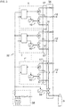
- Fig. 3 illustrates a simplified schematic block diagram of an exemplary fluid pressure control system 32 comprising several identical fluid pressure control apparatuses 1, 1', 1" and an on-off solenoid valve 33.
- the connection manifold 34 is designed as a single part to connect all pressure control apparatuses 1, 1', 1" at their respective fluid inlets 11 through the on-off solenoid valve 33 to the fluid source 9, here the gas bottle.
- the pressure control apparatuses 1, 1', 1" individually control delivery of the carrier gas 6 to different points of use in the process gas chromatograph.
- the fluid pressure control apparatuses 1, 1', 1" and the on-off solenoid valve 33 are each intrinsically safe and are commonly powered via an intrinsic safety barrier 35 which limits the current, voltage and total energy delivered to them.
Landscapes
- Physics & Mathematics (AREA)
- Fluid Mechanics (AREA)
- General Physics & Mathematics (AREA)
- Automation & Control Theory (AREA)
- Engineering & Computer Science (AREA)
- General Health & Medical Sciences (AREA)
- Biochemistry (AREA)
- Analytical Chemistry (AREA)
- Immunology (AREA)
- Pathology (AREA)
- Chemical & Material Sciences (AREA)
- Life Sciences & Earth Sciences (AREA)
- Health & Medical Sciences (AREA)
- Magnetically Actuated Valves (AREA)
- Fluid-Driven Valves (AREA)
Description
- The invention relates to a fluid pressure control apparatus.
- It further relates to a fluid pressure control system comprising at least two of such fluid pressure control apparatuses.
- The fluid pressure control apparatus of concern herein provides a regulated fluid pressure output that is equal to a pressure set point value applied to the control apparatus. To that end, the apparatus may comprise a proportional solenoid valve operatively connected between a fluid inlet and a fluid outlet and a pressure sensor fluidically coupled to the fluid outlet. An electronic controller generates and outputs a control signal to the solenoid valve in dependence on a control deviation between the measured or sensed pressure and the pressure set point value.
- The mentioned pressure apparatuses or systems may be used in gas analysis equipment, for example, for regulating a carrier gas flow in a process gas chromatograph. Gas analysis equipment is often located in harsh environment where explosive gases may be present. Thus, safety precautions must be taken to prevent the gases from igniting. To that end, the one or more control apparatuses may be arranged in a pressurized enclosure that uses overpressure to prevent an explosive atmosphere from entering. The overpressure may be maintained by continuous purging, which can be costly.
- In flameproof enclosure protection, an explosion occurring inside the enclosure is prevented from spreading and igniting the explosive atmosphere surrounding the enclosure. This, however, leads to very robust and expensive housings and furthermore to poor dissipation of heat generated by the fluid pressure control apparatuses inside the housing.
- In intrinsic safety protection, the current and voltage are limited to such an extent that no spark or thermal effect can cause an explosive atmosphere to ignite. There are various intrinsic safety standards set forth by various certifying agencies including International Electrical Commission (IEC) IEC 60079-11, Factory Mutual (FM) 3610, Underwriters Laboratories (UL) UL913, etc. Prior art concerning fluid pressure control using a solenoid valve can be found in
US 2012/103063 A1 , inDE 33 18 821 A1 and inUS 9 568 095 B2 - The solenoid valve of the fluid pressure control apparatus is an electromechanical device in which the solenoid (electric coil) uses an electric current to generate a magnetic field and thereby operate a valve member. Standard solenoid valves require a not insignificant amount of electrical power to move the valve member (disc) against a spring loading from the valve seat (closed position) to a more or less open position and hold the valve member in the open position. This holds in particular, when the solenoid valve is not only used as a proportional valve but also to safely shut off the gas flow when de-energized. In this case, the spring load will be set to a higher value, thus requiring even more power to both open the valve and keep it open.
- It is therefore an object of the present invention to provide a fluid pressure control apparatus and system with reduced power consumption and heat generation, in particular for use in gas analysis equipment located in hazardous areas where explosive gas or dust might be present.
- According to the invention, this object is achieved by the fluid pressure control apparatus defined in
claim 1, the fluid pressure control system ofclaim 4 or the gas chromatographs ofclaims - Further embodiments of the invention are set forth in the remaining claims.
- Thus, a subject of the invention is a fluid pressure control apparatus comprising:
- a proportional solenoid valve operatively connected between a fluid inlet and a fluid outlet,
- a pressure sensor fluidically coupled to the fluid outlet,
- an electronic controller adapted to receive a first signal from the pressure sensor, to receive a second signal corresponding to a pressure set point and to generate and output a control signal to the solenoid valve,
- said solenoid valve having a rest position between opened and closed and
- said electronic controller being further adapted to generate the control signal with either of opposite polarities to move the valve in either of opposite directions from its rest position.
- A subject of invention is also a fluid pressure control system comprising at least two of such fluid pressure control apparatuses, wherein the fluid inlets of the pressure control apparatuses are fluidically connected and wherein an on-off solenoid valve is operatively arranged upstream of the fluid inlets.
- A further subject of the invention is a gas chromatograph comprising at least one fluid pressure control apparatus or system.
- Assuming that in a standard solenoid valve about 60% of the maximum control power is needed to release the valve member from the seat, the electrical power for controlling the valve in the range between the closed and fully open positions will be between 60% and 100% of said maximum control power. According to the invention, however, the solenoid valve has its rest or neutral position between fully opened and closed and is controlled with a signal having one or the other of two polarities, i.e. a positive or negative voltage or current. Therefore, if the rest position is in the middle between the outer positions, the valve needs only about 20% of the power required by the mentioned standard valve for moving into either the closed or fully open position. In order to safely shut off the valve in, e.g., the case of an emergency, an additional but low percentage of power may be needed to press the valve member with a predetermined minimum force in the seat. To this end, the rest position may be slightly shifted from the exact middle towards the closed position.
- One advantage of the invention is that, with less power consumption, less heat will produced by the solenoid valve. Another advantage is that the solenoid (coil) may be much smaller, thus reducing the inductance. Both factors significantly contribute to designing the fluid pressure control apparatus in such a way that it meets prescribed intrinsic safety standards.
- Any intrinsically safe electrical device in a hazardous area must be supplied from an intrinsic safety barrier which limits the current, voltage and total energy delivered to the device. As the power requirement of the solenoid valve of the fluid pressure control apparatus according to the invention can amount to just 20% of that of the standard valve, as many as five control apparatuses can be connected to one intrinsic safety barrier opposed to only one previous control apparatus.
- This advantageously allows for arranging two or more fluid pressure control apparatuses in a fluid pressure control system for individually controlled delivery of a fluid from a single source to different points of use, e.g., in a process gas chromatograph with a multi-column system. To this end, the fluid inlets of the different pressure control apparatuses are fluidically connected to the fluid source, with, advantageously, an on-off solenoid valve operatively arranged between the fluid source and the fluid inlets of the pressure control apparatuses. Thus, while the proportional solenoid valves are allowed to leak, the on-off solenoid valve ensures a safe shut off flow, e.g., at power off in case of emergency or during times of calibration, when no fluid is allowed to flow. As an on-off valve is much simpler in design and uses much less power than a proportional valve, it is very beneficial to shift the shut off function from the proportional valves to the single on-off valve.
- The invention will now be described by way of example and with reference to the accompanying drawing, in which
- Fig. 1
- is a simplified schematic block diagram of an exemplary fluid pressure control apparatus,
- Fig. 2
- is an exemplary embodiment of the proportional solenoid valve and
- Fig. 3
- is a simplified schematic block diagram of an exemplary fluid pressure control system.
-
Fig. 1 illustrates a fluidpressure control apparatus 1 which is arranged in anelectronics housing 2 of, e.g., aprocess gas chromatograph 3 for analyzing agas mixture 4. A sample of thegas mixture 4 is supplied to adosing unit 5 for injecting a specified dose of the gas sample into a carrier gas stream 6 (such as nitrogen or helium). Thecarrier gas 6 carries the sample through one orseveral separation columns 7 where separation of the components of thegas mixture 4 takes place. The gas components successively eluting from thecolumn 7 are detected and quantitatively identified by adetector 8. - The
carrier gas 6 is taken from agas source 9, here a gas bottle. The fluidpressure control apparatus 1 serves to keep the pressure of thecarrier gas 6 delivered to thecolumn 7 at a predetermined level to provide an optimum performance over the column setpoint ranges. Thepressure control apparatus 1 contains aproportional solenoid valve 10 that is operatively connected between afluid inlet 11 to which thegas source 9 is connected and afluid outlet 12 to which thedosing unit 5 is connected. Apressure sensor 13 measures the pressure of thecarrier gas 6 at thefluid outlet 12 against the atmospheric pressure. To that end, thepressure sensor 13 is fluidically coupled to thefluid outlet 12 on one side and on the other side via aflame arrester 14 to the surrounding atmosphere. Thefluid inlet 11 is in fluid communication with anadditional fluid port 15 which allows connecting the fluid inlet of a second fluid pressure control apparatus (not shown) to thegas source 9. In the illustrated example, thefluid inlet 11,fluid outlet 12 and theadditional fluid port 15 are realized as tube fittings on aconnection manifold 16 that also contains theflame arrester 14. Thepressure control apparatus 1 comprises afluid interface 17 in the form of another manifold that provides fluidic connection between thevalve 10 and thepressure sensor 13 and to theconnection manifold 16. - The
pressure control apparatus 1 further contains anelectronic controller 18 which is powered via aline 19 and which generates and outputs acontrol signal 20 to theproportional solenoid valve 10 in dependence on a control deviation between afirst signal 21 provided by thepressure sensor 13 and representative of the measured or sensed pressure and a pressure set point value 22. -
Fig. 2 shows a schematic illustration of an embodiment of theproportional solenoid valve 10. Thevalve 10 comprises avalve housing 23 including therein avalve seat 24, fluid supply and dischargepassages valve seat 24, the fluid inlet 11 (Fig. 1 ) connected to thefluid supply passage 25 and thefluid outlet 12 connected to thefluid discharge passage 26. In thehousing 11, further, avalve member 27 at one end of aplunger 28 is disposed to engage with and disengage from thevalve seat 24. Apermanent magnet 29 at the other end of theplunger 28 is arranged to be laterally movable in a gap of asolenoid 30. Aspring element 31 holds theplunger 28 in a rest position, where thevalve member 27 is situated somewhere in between, preferably in the middle between the closed position and the full open position of thevalve 10. Depending on the polarity of a voltage or current applied to the solenoid, the permanent magnet is either pulled-in towards thesolenoid 10, or pushed-out from it. - Referring back to
Fig.1 , theelectronic controller 18 is adapted to generate thecontrol signal 20 with either of opposite polarities, i.e. a positive or negative voltage or current, in order to move thevalve member 27 in either of opposite directions from its rest position. -
Fig. 3 illustrates a simplified schematic block diagram of an exemplary fluidpressure control system 32 comprising several identical fluidpressure control apparatuses solenoid valve 33. In contrast to the example shown inFig. 1 , theconnection manifold 34 is designed as a single part to connect allpressure control apparatuses respective fluid inlets 11 through the on-offsolenoid valve 33 to thefluid source 9, here the gas bottle. Thepressure control apparatuses carrier gas 6 to different points of use in the process gas chromatograph. - The fluid
pressure control apparatuses solenoid valve 33 are each intrinsically safe and are commonly powered via anintrinsic safety barrier 35 which limits the current, voltage and total energy delivered to them.
Claims (8)
- A fluid pressure control apparatus (1) comprising:a proportional solenoid valve (10) operatively connected between a fluid inlet (11) and a fluid outlet (12),a pressure sensor (13) fluidically coupled to the fluid outlet (12),an electronic controller (18) adapted to receive a first signal (21) from the pressure sensor (13), to receive a second signal (22) corresponding to a pressure set point and to generate and output a control signal (20) to the solenoid valve (10),characterised in said solenoid valve (10) having a rest position between opened and closed andsaid electronic controller (18) being further adapted to generate the control signal (20) with either of opposite polarities to move the valve (10) in either of opposite directions from its rest position.
- The fluid pressure control apparatus (1) of claim 1 being designed to meet an intrinsic safety standard.
- The fluid pressure control apparatus (1) of claims 1 or 2, wherein said intrinsic safety standard is IEC 60079-11.
- A fluid pressure control system (32) comprising at least two of the fluid pressure control apparatuses (1, 1', 1") of any preceding claim, wherein the fluid inlets (11, 11', 11'') of the pressure control apparatuses (1, 1', 1") are fluidically connected and wherein an on-off solenoid valve (33) is operatively arranged upstream of the fluid inlets (11, 11', 11").
- The fluid pressure control system (32) of claim 4, wherein the on-off solenoid valve (33) is designed to be driven at a low power that meets an intrinsic safety standard.
- The fluid pressure control system (32) of claims 4 or 5, wherein said intrinsic safety standard is IEC 60079-11.
- A gas chromatograph (3) comprising at least one at least one fluid pressure control apparatus (1) of one of claims 1 to 3.
- A gas chromatograph (3) comprising at least one fluid pressure control (32) system of one of claims 4 to 6.
Priority Applications (3)
| Application Number | Priority Date | Filing Date | Title |
|---|---|---|---|
| EP18196354.7A EP3627274B1 (en) | 2018-09-24 | 2018-09-24 | Fluid pressure control apparatus and system |
| CN201910893501.XA CN110940765B (en) | 2018-09-24 | 2019-09-20 | Fluid pressure control device and system and gas chromatograph |
| US16/579,315 US11215588B2 (en) | 2018-09-24 | 2019-09-23 | Fluid pressure control apparatus and system |
Applications Claiming Priority (1)
| Application Number | Priority Date | Filing Date | Title |
|---|---|---|---|
| EP18196354.7A EP3627274B1 (en) | 2018-09-24 | 2018-09-24 | Fluid pressure control apparatus and system |
Publications (2)
| Publication Number | Publication Date |
|---|---|
| EP3627274A1 EP3627274A1 (en) | 2020-03-25 |
| EP3627274B1 true EP3627274B1 (en) | 2020-10-28 |
Family
ID=63683099
Family Applications (1)
| Application Number | Title | Priority Date | Filing Date |
|---|---|---|---|
| EP18196354.7A Active EP3627274B1 (en) | 2018-09-24 | 2018-09-24 | Fluid pressure control apparatus and system |
Country Status (3)
| Country | Link |
|---|---|
| US (1) | US11215588B2 (en) |
| EP (1) | EP3627274B1 (en) |
| CN (1) | CN110940765B (en) |
Cited By (1)
| Publication number | Priority date | Publication date | Assignee | Title |
|---|---|---|---|---|
| WO2023052818A1 (en) | 2021-09-30 | 2023-04-06 | Siemens Aktiengesellschaft | Gas analyzer with improved architecture for operation in potentially hazardous environment |
Families Citing this family (2)
| Publication number | Priority date | Publication date | Assignee | Title |
|---|---|---|---|---|
| EP3882737B1 (en) | 2020-03-20 | 2022-04-27 | Siemens Aktiengesellschaft | Fluid pressure control apparatus |
| US20250052731A1 (en) * | 2023-08-11 | 2025-02-13 | Agilent Technologies, Inc. | Methods and systems for estimating gas supply pressure |
Family Cites Families (10)
| Publication number | Priority date | Publication date | Assignee | Title |
|---|---|---|---|---|
| US2427970A (en) * | 1943-01-25 | 1947-09-23 | Ex Cell O Corp | Hydraulic control system for machine tools and the like |
| DE3318821A1 (en) * | 1983-05-24 | 1984-11-29 | IGEBA Gerätebau GmbH, 8961 Weitnau | Cut-off device for smoke generators |
| WO2004109420A1 (en) * | 2003-06-09 | 2004-12-16 | Ckd Corporation | Relative pressure control system and relative flow rate control system |
| CN101728053A (en) * | 2008-10-21 | 2010-06-09 | 杨晟 | Bistable electromagnetic actuator and product using same |
| US20100140519A1 (en) * | 2008-12-04 | 2010-06-10 | General Electric Company | Electromagnetic actuators |
| CN201555832U (en) * | 2009-12-16 | 2010-08-18 | 上海神开石油化工装备股份有限公司 | Electronic pressure controller for gas chromatograph |
| CN102103381B (en) * | 2009-12-16 | 2014-06-25 | 上海神开石油化工装备股份有限公司 | Electron pressure controller |
| US9429499B2 (en) * | 2010-10-29 | 2016-08-30 | Agilent Technologies, Inc. | Methods, devices, and systems for controlling the rate of gas depressurization within a vial containing a gas sample |
| DE102013221453A1 (en) * | 2013-10-23 | 2015-04-23 | Conti Temic Microelectronic Gmbh | Regulation of a hydraulic pressure of a flow gear |
| CN105334278B (en) * | 2015-12-10 | 2017-05-31 | 新疆工程学院 | Gas chromatograph inlet end trace gas controller |
-
2018
- 2018-09-24 EP EP18196354.7A patent/EP3627274B1/en active Active
-
2019
- 2019-09-20 CN CN201910893501.XA patent/CN110940765B/en active Active
- 2019-09-23 US US16/579,315 patent/US11215588B2/en active Active
Non-Patent Citations (1)
| Title |
|---|
| None * |
Cited By (3)
| Publication number | Priority date | Publication date | Assignee | Title |
|---|---|---|---|---|
| WO2023052818A1 (en) | 2021-09-30 | 2023-04-06 | Siemens Aktiengesellschaft | Gas analyzer with improved architecture for operation in potentially hazardous environment |
| WO2023052870A1 (en) | 2021-09-30 | 2023-04-06 | Siemens Aktiengesellschaft | Gas analyzer with improved architecture for operation in potentially hazardous environment |
| US12222338B2 (en) | 2021-09-30 | 2025-02-11 | Gas Chromatography Systems Maxum Gmbh | Gas analyzer with improved architecture for operation in potentially hazardous environments |
Also Published As
| Publication number | Publication date |
|---|---|
| EP3627274A1 (en) | 2020-03-25 |
| US20200096487A1 (en) | 2020-03-26 |
| CN110940765B (en) | 2022-08-30 |
| US11215588B2 (en) | 2022-01-04 |
| CN110940765A (en) | 2020-03-31 |
Similar Documents
| Publication | Publication Date | Title |
|---|---|---|
| US11215588B2 (en) | Fluid pressure control apparatus and system | |
| US4624443A (en) | Fluid-flow control valve | |
| CA1276521C (en) | Fluid flow control valve | |
| TWI530585B (en) | Vacuum control system and vacuum control valve | |
| ES2390669T3 (en) | Gas regulation and safety valve | |
| US5020774A (en) | Variable orifice flow regulator | |
| KR101690810B1 (en) | In-line pressure regulators | |
| US5651385A (en) | Servo drive operated by a pressure medium | |
| CA2031170A1 (en) | Gasoline dispenser with valve control through an air gap | |
| EP2655800A2 (en) | Memory alloy-actuated apparatus and methods for making and using the same | |
| KR20130115252A (en) | Gas valve unit | |
| US20110272048A1 (en) | Arrangement of pulse-modulated quick-acting valves, tank system, method for preparing a required mass flow and use of a tank system | |
| WO2001007809A1 (en) | Low power solenoid proportional valve | |
| EP3882737B1 (en) | Fluid pressure control apparatus | |
| CN109641578B (en) | Pre-control unit, regulating system and method for producing the same | |
| US2769912A (en) | Shut-off valve | |
| US10578591B2 (en) | Gas chromatograph | |
| US2977966A (en) | Fluid pressure operated control devices | |
| US3455323A (en) | Gas regulator with electronic pressure control | |
| RU2451856C1 (en) | Normally closed electromagnetic gate valve | |
| WO2002033763A3 (en) | Device for supplying an operating gas to a fuel cell arrangement | |
| JP4861187B2 (en) | Magnet Operated Electrical Circuit Device for Fluidic Valve Drive Control | |
| WO2015168351A1 (en) | Fluid sample system and method | |
| US20030222235A1 (en) | Modular shut-off valve apparatus | |
| JPS62106103A (en) | Pneumatic interface device |
Legal Events
| Date | Code | Title | Description |
|---|---|---|---|
| PUAI | Public reference made under article 153(3) epc to a published international application that has entered the european phase |
Free format text: ORIGINAL CODE: 0009012 |
|
| STAA | Information on the status of an ep patent application or granted ep patent |
Free format text: STATUS: REQUEST FOR EXAMINATION WAS MADE |
|
| 17P | Request for examination filed |
Effective date: 20190617 |
|
| AK | Designated contracting states |
Kind code of ref document: A1 Designated state(s): AL AT BE BG CH CY CZ DE DK EE ES FI FR GB GR HR HU IE IS IT LI LT LU LV MC MK MT NL NO PL PT RO RS SE SI SK SM TR |
|
| AX | Request for extension of the european patent |
Extension state: BA ME |
|
| REG | Reference to a national code |
Ref country code: DE Ref legal event code: R079 Ref document number: 602018009102 Country of ref document: DE Free format text: PREVIOUS MAIN CLASS: G05D0016000000 Ipc: G05D0016200000 |
|
| GRAP | Despatch of communication of intention to grant a patent |
Free format text: ORIGINAL CODE: EPIDOSNIGR1 |
|
| STAA | Information on the status of an ep patent application or granted ep patent |
Free format text: STATUS: GRANT OF PATENT IS INTENDED |
|
| RIC1 | Information provided on ipc code assigned before grant |
Ipc: G05D 16/20 20060101AFI20200609BHEP |
|
| GRAJ | Information related to disapproval of communication of intention to grant by the applicant or resumption of examination proceedings by the epo deleted |
Free format text: ORIGINAL CODE: EPIDOSDIGR1 |
|
| STAA | Information on the status of an ep patent application or granted ep patent |
Free format text: STATUS: REQUEST FOR EXAMINATION WAS MADE |
|
| INTG | Intention to grant announced |
Effective date: 20200714 |
|
| GRAP | Despatch of communication of intention to grant a patent |
Free format text: ORIGINAL CODE: EPIDOSNIGR1 |
|
| STAA | Information on the status of an ep patent application or granted ep patent |
Free format text: STATUS: GRANT OF PATENT IS INTENDED |
|
| INTC | Intention to grant announced (deleted) | ||
| GRAS | Grant fee paid |
Free format text: ORIGINAL CODE: EPIDOSNIGR3 |
|
| INTG | Intention to grant announced |
Effective date: 20200820 |
|
| GRAA | (expected) grant |
Free format text: ORIGINAL CODE: 0009210 |
|
| STAA | Information on the status of an ep patent application or granted ep patent |
Free format text: STATUS: THE PATENT HAS BEEN GRANTED |
|
| AK | Designated contracting states |
Kind code of ref document: B1 Designated state(s): AL AT BE BG CH CY CZ DE DK EE ES FI FR GB GR HR HU IE IS IT LI LT LU LV MC MK MT NL NO PL PT RO RS SE SI SK SM TR |
|
| REG | Reference to a national code |
Ref country code: GB Ref legal event code: FG4D |
|
| REG | Reference to a national code |
Ref country code: CH Ref legal event code: EP |
|
| REG | Reference to a national code |
Ref country code: AT Ref legal event code: REF Ref document number: 1328855 Country of ref document: AT Kind code of ref document: T Effective date: 20201115 |
|
| REG | Reference to a national code |
Ref country code: DE Ref legal event code: R096 Ref document number: 602018009102 Country of ref document: DE |
|
| REG | Reference to a national code |
Ref country code: IE Ref legal event code: FG4D |
|
| REG | Reference to a national code |
Ref country code: NL Ref legal event code: FP |
|
| REG | Reference to a national code |
Ref country code: AT Ref legal event code: MK05 Ref document number: 1328855 Country of ref document: AT Kind code of ref document: T Effective date: 20201028 |
|
| PG25 | Lapsed in a contracting state [announced via postgrant information from national office to epo] |
Ref country code: FI Free format text: LAPSE BECAUSE OF FAILURE TO SUBMIT A TRANSLATION OF THE DESCRIPTION OR TO PAY THE FEE WITHIN THE PRESCRIBED TIME-LIMIT Effective date: 20201028 Ref country code: PT Free format text: LAPSE BECAUSE OF FAILURE TO SUBMIT A TRANSLATION OF THE DESCRIPTION OR TO PAY THE FEE WITHIN THE PRESCRIBED TIME-LIMIT Effective date: 20210301 Ref country code: RS Free format text: LAPSE BECAUSE OF FAILURE TO SUBMIT A TRANSLATION OF THE DESCRIPTION OR TO PAY THE FEE WITHIN THE PRESCRIBED TIME-LIMIT Effective date: 20201028 Ref country code: GR Free format text: LAPSE BECAUSE OF FAILURE TO SUBMIT A TRANSLATION OF THE DESCRIPTION OR TO PAY THE FEE WITHIN THE PRESCRIBED TIME-LIMIT Effective date: 20210129 Ref country code: NO Free format text: LAPSE BECAUSE OF FAILURE TO SUBMIT A TRANSLATION OF THE DESCRIPTION OR TO PAY THE FEE WITHIN THE PRESCRIBED TIME-LIMIT Effective date: 20210128 |
|
| REG | Reference to a national code |
Ref country code: LT Ref legal event code: MG4D |
|
| PG25 | Lapsed in a contracting state [announced via postgrant information from national office to epo] |
Ref country code: SE Free format text: LAPSE BECAUSE OF FAILURE TO SUBMIT A TRANSLATION OF THE DESCRIPTION OR TO PAY THE FEE WITHIN THE PRESCRIBED TIME-LIMIT Effective date: 20201028 Ref country code: LV Free format text: LAPSE BECAUSE OF FAILURE TO SUBMIT A TRANSLATION OF THE DESCRIPTION OR TO PAY THE FEE WITHIN THE PRESCRIBED TIME-LIMIT Effective date: 20201028 Ref country code: IS Free format text: LAPSE BECAUSE OF FAILURE TO SUBMIT A TRANSLATION OF THE DESCRIPTION OR TO PAY THE FEE WITHIN THE PRESCRIBED TIME-LIMIT Effective date: 20210228 Ref country code: PL Free format text: LAPSE BECAUSE OF FAILURE TO SUBMIT A TRANSLATION OF THE DESCRIPTION OR TO PAY THE FEE WITHIN THE PRESCRIBED TIME-LIMIT Effective date: 20201028 Ref country code: BG Free format text: LAPSE BECAUSE OF FAILURE TO SUBMIT A TRANSLATION OF THE DESCRIPTION OR TO PAY THE FEE WITHIN THE PRESCRIBED TIME-LIMIT Effective date: 20210128 Ref country code: AT Free format text: LAPSE BECAUSE OF FAILURE TO SUBMIT A TRANSLATION OF THE DESCRIPTION OR TO PAY THE FEE WITHIN THE PRESCRIBED TIME-LIMIT Effective date: 20201028 Ref country code: ES Free format text: LAPSE BECAUSE OF FAILURE TO SUBMIT A TRANSLATION OF THE DESCRIPTION OR TO PAY THE FEE WITHIN THE PRESCRIBED TIME-LIMIT Effective date: 20201028 |
|
| PG25 | Lapsed in a contracting state [announced via postgrant information from national office to epo] |
Ref country code: HR Free format text: LAPSE BECAUSE OF FAILURE TO SUBMIT A TRANSLATION OF THE DESCRIPTION OR TO PAY THE FEE WITHIN THE PRESCRIBED TIME-LIMIT Effective date: 20201028 |
|
| REG | Reference to a national code |
Ref country code: DE Ref legal event code: R097 Ref document number: 602018009102 Country of ref document: DE |
|
| PG25 | Lapsed in a contracting state [announced via postgrant information from national office to epo] |
Ref country code: LT Free format text: LAPSE BECAUSE OF FAILURE TO SUBMIT A TRANSLATION OF THE DESCRIPTION OR TO PAY THE FEE WITHIN THE PRESCRIBED TIME-LIMIT Effective date: 20201028 Ref country code: RO Free format text: LAPSE BECAUSE OF FAILURE TO SUBMIT A TRANSLATION OF THE DESCRIPTION OR TO PAY THE FEE WITHIN THE PRESCRIBED TIME-LIMIT Effective date: 20201028 Ref country code: SK Free format text: LAPSE BECAUSE OF FAILURE TO SUBMIT A TRANSLATION OF THE DESCRIPTION OR TO PAY THE FEE WITHIN THE PRESCRIBED TIME-LIMIT Effective date: 20201028 Ref country code: SM Free format text: LAPSE BECAUSE OF FAILURE TO SUBMIT A TRANSLATION OF THE DESCRIPTION OR TO PAY THE FEE WITHIN THE PRESCRIBED TIME-LIMIT Effective date: 20201028 Ref country code: CZ Free format text: LAPSE BECAUSE OF FAILURE TO SUBMIT A TRANSLATION OF THE DESCRIPTION OR TO PAY THE FEE WITHIN THE PRESCRIBED TIME-LIMIT Effective date: 20201028 Ref country code: EE Free format text: LAPSE BECAUSE OF FAILURE TO SUBMIT A TRANSLATION OF THE DESCRIPTION OR TO PAY THE FEE WITHIN THE PRESCRIBED TIME-LIMIT Effective date: 20201028 |
|
| PG25 | Lapsed in a contracting state [announced via postgrant information from national office to epo] |
Ref country code: DK Free format text: LAPSE BECAUSE OF FAILURE TO SUBMIT A TRANSLATION OF THE DESCRIPTION OR TO PAY THE FEE WITHIN THE PRESCRIBED TIME-LIMIT Effective date: 20201028 |
|
| PLBE | No opposition filed within time limit |
Free format text: ORIGINAL CODE: 0009261 |
|
| STAA | Information on the status of an ep patent application or granted ep patent |
Free format text: STATUS: NO OPPOSITION FILED WITHIN TIME LIMIT |
|
| 26N | No opposition filed |
Effective date: 20210729 |
|
| PG25 | Lapsed in a contracting state [announced via postgrant information from national office to epo] |
Ref country code: AL Free format text: LAPSE BECAUSE OF FAILURE TO SUBMIT A TRANSLATION OF THE DESCRIPTION OR TO PAY THE FEE WITHIN THE PRESCRIBED TIME-LIMIT Effective date: 20201028 |
|
| PG25 | Lapsed in a contracting state [announced via postgrant information from national office to epo] |
Ref country code: SI Free format text: LAPSE BECAUSE OF FAILURE TO SUBMIT A TRANSLATION OF THE DESCRIPTION OR TO PAY THE FEE WITHIN THE PRESCRIBED TIME-LIMIT Effective date: 20201028 |
|
| REG | Reference to a national code |
Ref country code: CH Ref legal event code: PL |
|
| PG25 | Lapsed in a contracting state [announced via postgrant information from national office to epo] |
Ref country code: IS Free format text: LAPSE BECAUSE OF FAILURE TO SUBMIT A TRANSLATION OF THE DESCRIPTION OR TO PAY THE FEE WITHIN THE PRESCRIBED TIME-LIMIT Effective date: 20210228 Ref country code: MC Free format text: LAPSE BECAUSE OF FAILURE TO SUBMIT A TRANSLATION OF THE DESCRIPTION OR TO PAY THE FEE WITHIN THE PRESCRIBED TIME-LIMIT Effective date: 20201028 |
|
| PG25 | Lapsed in a contracting state [announced via postgrant information from national office to epo] |
Ref country code: LU Free format text: LAPSE BECAUSE OF NON-PAYMENT OF DUE FEES Effective date: 20210924 Ref country code: IE Free format text: LAPSE BECAUSE OF NON-PAYMENT OF DUE FEES Effective date: 20210924 |
|
| PG25 | Lapsed in a contracting state [announced via postgrant information from national office to epo] |
Ref country code: LI Free format text: LAPSE BECAUSE OF NON-PAYMENT OF DUE FEES Effective date: 20210930 Ref country code: CH Free format text: LAPSE BECAUSE OF NON-PAYMENT OF DUE FEES Effective date: 20210930 |
|
| PG25 | Lapsed in a contracting state [announced via postgrant information from national office to epo] |
Ref country code: CY Free format text: LAPSE BECAUSE OF FAILURE TO SUBMIT A TRANSLATION OF THE DESCRIPTION OR TO PAY THE FEE WITHIN THE PRESCRIBED TIME-LIMIT Effective date: 20201028 |
|
| PG25 | Lapsed in a contracting state [announced via postgrant information from national office to epo] |
Ref country code: HU Free format text: LAPSE BECAUSE OF FAILURE TO SUBMIT A TRANSLATION OF THE DESCRIPTION OR TO PAY THE FEE WITHIN THE PRESCRIBED TIME-LIMIT; INVALID AB INITIO Effective date: 20180924 |
|
| REG | Reference to a national code |
Ref country code: NL Ref legal event code: PD Owner name: GAS CHROMATOGRAPHY SYSTEMS MAXUM GMBH; DE Free format text: DETAILS ASSIGNMENT: CHANGE OF OWNER(S), ASSIGNMENT; FORMER OWNER NAME: SIEMENS AKTIENGESELLSCHAFT Effective date: 20240319 |
|
| REG | Reference to a national code |
Ref country code: DE Ref legal event code: R081 Ref document number: 602018009102 Country of ref document: DE Owner name: GAS CHROMATOGRAPHY SYSTEMS MAXUM GMBH, DE Free format text: FORMER OWNER: SIEMENS AKTIENGESELLSCHAFT, 80333 MUENCHEN, DE |
|
| REG | Reference to a national code |
Ref country code: GB Ref legal event code: 732E Free format text: REGISTERED BETWEEN 20240321 AND 20240327 |
|
| PG25 | Lapsed in a contracting state [announced via postgrant information from national office to epo] |
Ref country code: MK Free format text: LAPSE BECAUSE OF FAILURE TO SUBMIT A TRANSLATION OF THE DESCRIPTION OR TO PAY THE FEE WITHIN THE PRESCRIBED TIME-LIMIT Effective date: 20201028 |
|
| REG | Reference to a national code |
Ref country code: BE Ref legal event code: PD Owner name: GAS CHROMATOGRAPHY SYSTEMS MAXUM GMBH; DE Free format text: DETAILS ASSIGNMENT: CHANGE OF OWNER(S), ASSIGNMENT; FORMER OWNER NAME: SIEMENS AKTIENGESELLSCHAFT Effective date: 20240313 |
|
| PG25 | Lapsed in a contracting state [announced via postgrant information from national office to epo] |
Ref country code: TR Free format text: LAPSE BECAUSE OF FAILURE TO SUBMIT A TRANSLATION OF THE DESCRIPTION OR TO PAY THE FEE WITHIN THE PRESCRIBED TIME-LIMIT Effective date: 20201028 |
|
| PG25 | Lapsed in a contracting state [announced via postgrant information from national office to epo] |
Ref country code: MT Free format text: LAPSE BECAUSE OF FAILURE TO SUBMIT A TRANSLATION OF THE DESCRIPTION OR TO PAY THE FEE WITHIN THE PRESCRIBED TIME-LIMIT Effective date: 20201028 |
|
| PGFP | Annual fee paid to national office [announced via postgrant information from national office to epo] |
Ref country code: DE Payment date: 20250919 Year of fee payment: 8 |
|
| PGFP | Annual fee paid to national office [announced via postgrant information from national office to epo] |
Ref country code: NL Payment date: 20250918 Year of fee payment: 8 Ref country code: IT Payment date: 20250923 Year of fee payment: 8 |
|
| PGFP | Annual fee paid to national office [announced via postgrant information from national office to epo] |
Ref country code: BE Payment date: 20250918 Year of fee payment: 8 Ref country code: GB Payment date: 20250919 Year of fee payment: 8 |
|
| PGFP | Annual fee paid to national office [announced via postgrant information from national office to epo] |
Ref country code: FR Payment date: 20250922 Year of fee payment: 8 |