EP3627151A1 - Column tube for chromatography, and column for chromatography employing same - Google Patents
Column tube for chromatography, and column for chromatography employing same Download PDFInfo
- Publication number
- EP3627151A1 EP3627151A1 EP18802540.7A EP18802540A EP3627151A1 EP 3627151 A1 EP3627151 A1 EP 3627151A1 EP 18802540 A EP18802540 A EP 18802540A EP 3627151 A1 EP3627151 A1 EP 3627151A1
- Authority
- EP
- European Patent Office
- Prior art keywords
- column
- column tube
- chromatography
- tube
- polishing
- Prior art date
- Legal status (The legal status is an assumption and is not a legal conclusion. Google has not performed a legal analysis and makes no representation as to the accuracy of the status listed.)
- Granted
Links
Images


Classifications
-
- G—PHYSICS
- G01—MEASURING; TESTING
- G01N—INVESTIGATING OR ANALYSING MATERIALS BY DETERMINING THEIR CHEMICAL OR PHYSICAL PROPERTIES
- G01N30/00—Investigating or analysing materials by separation into components using adsorption, absorption or similar phenomena or using ion-exchange, e.g. chromatography or field flow fractionation
- G01N30/02—Column chromatography
- G01N30/60—Construction of the column
-
- G—PHYSICS
- G01—MEASURING; TESTING
- G01N—INVESTIGATING OR ANALYSING MATERIALS BY DETERMINING THEIR CHEMICAL OR PHYSICAL PROPERTIES
- G01N30/00—Investigating or analysing materials by separation into components using adsorption, absorption or similar phenomena or using ion-exchange, e.g. chromatography or field flow fractionation
- G01N30/02—Column chromatography
- G01N30/60—Construction of the column
- G01N30/6052—Construction of the column body
-
- B—PERFORMING OPERATIONS; TRANSPORTING
- B01—PHYSICAL OR CHEMICAL PROCESSES OR APPARATUS IN GENERAL
- B01D—SEPARATION
- B01D15/00—Separating processes involving the treatment of liquids with solid sorbents; Apparatus therefor
- B01D15/08—Selective adsorption, e.g. chromatography
- B01D15/10—Selective adsorption, e.g. chromatography characterised by constructional or operational features
- B01D15/22—Selective adsorption, e.g. chromatography characterised by constructional or operational features relating to the construction of the column
-
- B—PERFORMING OPERATIONS; TRANSPORTING
- B01—PHYSICAL OR CHEMICAL PROCESSES OR APPARATUS IN GENERAL
- B01D—SEPARATION
- B01D15/00—Separating processes involving the treatment of liquids with solid sorbents; Apparatus therefor
- B01D15/08—Selective adsorption, e.g. chromatography
- B01D15/26—Selective adsorption, e.g. chromatography characterised by the separation mechanism
- B01D15/40—Selective adsorption, e.g. chromatography characterised by the separation mechanism using supercritical fluid as mobile phase or eluent
-
- G—PHYSICS
- G01—MEASURING; TESTING
- G01N—INVESTIGATING OR ANALYSING MATERIALS BY DETERMINING THEIR CHEMICAL OR PHYSICAL PROPERTIES
- G01N30/00—Investigating or analysing materials by separation into components using adsorption, absorption or similar phenomena or using ion-exchange, e.g. chromatography or field flow fractionation
- G01N30/02—Column chromatography
- G01N2030/022—Column chromatography characterised by the kind of separation mechanism
- G01N2030/027—Liquid chromatography
-
- G—PHYSICS
- G01—MEASURING; TESTING
- G01N—INVESTIGATING OR ANALYSING MATERIALS BY DETERMINING THEIR CHEMICAL OR PHYSICAL PROPERTIES
- G01N30/00—Investigating or analysing materials by separation into components using adsorption, absorption or similar phenomena or using ion-exchange, e.g. chromatography or field flow fractionation
- G01N30/02—Column chromatography
Definitions
- the present invention relates to a novel column tube for chromatography, and a column for chromatography employing the same.
- a chromatograph such as a liquid chromatograph or a supercritical fluid chromatograph typically includes a column tube including a separating agent (stationary phase) for separating components to be separated, the components having been introduced into a fluid as a mobile phase.
- a separating agent stationary phase
- polishing of an inner surface of the tube is omitted, or a method of polishing with no directionality is used, in which the inner surface of the tube is uniformly polished as in electropolishing, or a method is used, in which buffing is performed in a circumferential direction of the tube.
- honing in which an inner circumferential surface of a tube material is polished by polishing processing implemented in a combination of a rotating motion and a reciprocating motion.
- Patent Document 1 the surface of an inner circumferential surface of a column tube has to be as smooth as possible.
- Patent Document 1 JP 09-119924 A
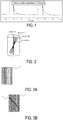
- a resulting chromatogram contains a long-lasting peak-shape abnormality, which is located near the end of a peak and referred to as a foot (see FIG. 1 ).
- An object of the present invention is to provide a column tube for chromatography that can prevent a peak shape abnormality referred to as a foot in a resulting chromatogram.
- a column tube for chromatography including, on an inner circumferential surface thereof, a plurality of polishing traces extending in a flow direction of a fluid.
- Embodiments of the present invention may include the following.
- a column tube for chromatography can be provided that can prevent a peak shape abnormality referred to as a foot.
- a column tube for chromatography (also simply referred to as a column tube) includes, on an inner circumferential surface thereof, a plurality of polishing traces extending in a flow direction of a fluid.
- polishing traces as used herein refer to streak-like polishing traces resulting from mechanical polishing.
- a single polishing trace may have a depth ranging from 0.01 to 50 ⁇ m, preferably from 0.05 to 20 ⁇ m, and more preferably from 0.1 to 5 ⁇ m.
- a single polishing trace may have a width ranging from 0.01 to 100 ⁇ m, preferably from 0.02 to 80 ⁇ m, and more preferably from 0.03 to 50 ⁇ m.
- the ratio, to a total number of polishing traces, of the number of polishing traces having a depth ranging from 0.01 to 50 ⁇ m and a width ranging from 0.01 to 100 ⁇ m is 70% or higher.
- the ratio is preferably 80% or higher, and more preferably 85% or higher.
- the ratio, and the width and depth of the polishing traces can be adjusted by adjusting the roughness of a polishing member that is used when the inner circumferential surface of the column tube is polished and adjusting a period of time for polishing.
- polishing traces which have appropriate widths and depths, at a higher percentage on the inner circumferential surface of the column tube contributes to exertion of the effect of the embodiment of the present invention.
- the depth and width of the polishing traces can be obtained by capturing an image of the inner circumferential surface of the column tube using a non-contact surface/layer cross-sectional shape measurement system and processing the image using a computer included in the system.
- the polishing traces extend in the flow direction of the fluid in the column tube (also referred to as a longitudinal axial direction or simply a vertical direction in a case where the length of the column tube in the flow direction of the fluid is larger than the outer diameter of the column tube). Not only polishing traces extending parallel to (an angle of 0°) the flow direction of the fluid in the column tube but also polishing traces extending at an angle of 30° or less as viewed from the flow direction of the fluid in the column tube are assumed to correspond to the wording "polishing traces extending in the flow direction of the fluid".
- the angle as viewed from the flow direction of the fluid is more preferably 20° or less, and still more preferably 10° or less. These are schematically illustrated in FIG. 2 .
- the polishing traces extending in the flow direction of the fluid preferably exist over an area that accounts for 90% or higher of a total area of the inner circumferential surface of the column tube.
- the existence of the polishing traces at such a rate on the inner circumferential surface of the column tube contributes to achieving the effect of the present invention.
- the ratio is more preferably 93% or higher, and still more preferably 95% or higher.
- polishing traces extending in the flow direction of the fluid are illustrated as polishing traces 1.
- the number of the polishing traces extending in the flow direction of the fluid is preferably 90% or higher and more preferably 93% or higher of the number of all the polishing traces including polishing traces that do not extend in the flow direction of the fluid.
- FIG. 3B illustrates an aspect in which polishing traces extending in the flow direction of the fluid are illustrated as the polishing traces 1 and in which polishing traces 2 exist extending in a direction different from the flow direction of the fluid (the polishing traces 2 exist at an angle higher than 30° with respect to the flow direction of the fluid).
- polishing traces extending in the flow direction of the fluid in the column tube and polishing traces extending in other directions coexist.
- polishing traces extending in other directions coexist.
- examples of the chromatography may include high performance liquid chromatography and supercritical fluid chromatography.
- Examples of a material for the column tube may include stainless steel and polyetheretherketone (PEEK).
- PEEK polyetheretherketone
- a tube material that is made from these materials and manufactured based on a known method can be utilized.
- the tube material is stainless steel
- a seamless pipe serving as a raw tube is prepared, and bright annealing, which is a known method, is performed to obtain a BA tube.
- the tip of the seamless BA tube is squeezed, and the tube is drawn out through a forming member referred to as a dice.
- a tube material for a column tube can be obtained.
- the tube material obtained via the process described above may be subjected to normal surface treatment, for example, electropolishing or chemical polishing, and the resultant tube material may be used for manufacturing a column tube according to the embodiment of the present invention.
- the tube material is made from PEEK
- a commercially available tube material may be used.
- the inner diameter of the column tube for chromatography a range used in normal chromatography can be employed.
- the inner diameter may be appropriately set to a range from 0.7 to 200 mm, depending on an intended use, e.g., analysis or sorting.
- Examples of an upper-limit inner diameter may include 70 mm, and may include 50 mm.
- the inner diameter may specifically be, for example, 0.7 mm, 1.0 mm, 1.5 mm, 2.0 mm, 3.0 m, 4.6 mm, 6.0 mm, 10 mm, 20 mm, 30 mm, 50 mm, 100 mm, 150 mm, or 200 mm.
- the length of the column tube for chromatography may be employed.
- the length may be less than 50 mm, equal to or greater than 50 mm and less than 100 mm, equal to or greater than 100 mm and less than 250 mm, or greater than 250 mm.
- a column tube according to the embodiment of the present invention filled with a separating agent for a target material may be utilized as a column body constituting a chromatographic column for liquid chromatography, supercritical fluid chromatography, or the like.
- the separating agent filled inside the column tube according to the embodiment of the present invention is not particularly limited, and examples of a separating agent include a separating agent used in size exclusion chromatography (SEC), a separating agent used in ion exchange chromatography (anion exchange or cation exchange), a separating agent used in adsorption chromatography, a separating agent used in partition (reverse phase) chromatography, a separating agent for optical isomers, and a separating agent of an inner-surface reverse phase type.
- SEC size exclusion chromatography
- anion exchange or cation exchange anion exchange or cation exchange
- a separating agent used in adsorption chromatography a separating agent used in partition (reverse phase) chromatography
- a separating agent for optical isomers a separating agent of an inner-surface reverse phase type.
- These separating agents are preferably particulate and typically have a particle diameter from 1 to 20 ⁇ m.
- the column tube according to the embodiment of the present invention functions as a column for chromatography by being internally filled with the separating agent as described above.
- a method for filling the above-described separating agent into the column tube is not limited, and a slurry method, for example, may be used.
- An aspect of the column for chromatography may include connectors provided at both end portions of the column tube and used to connect tubing, through which a fluid serving as a mobile phase flows, with a column tube (column body) internally filled with a separating agent.
- another aspect of the column tube for chromatography may include filters installed at both end portions of a column tube filled with a separating agent and include no connector as in the case of a cartridge column.
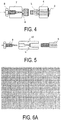
- FIG. 4 and FIG. 5 each illustrate a typical example, and the embodiment of the present invention is not limited to these examples.
- FIG. 4 is an enlarged view of a portion of an example in which outer surfaces of both end portions of a column tube 3 are used without performing any particular processing thereon.
- Connectors 7 provided at both end portions of the column tube 3 are fixed by being threadably engaged with nuts 4 via ferrules 5 fitted on both end portions of the column tube 3.
- a filter 6 may be provided inside each of the connectors 7.
- the connection in a case where the column body is connected to the tubing, through which a fluid flows, the connection can be achieved by screwing, into the connector 7, a setscrew 8 through which the tubing is passed.
- FIG. 5 is an enlarged view of a portion of an example in which the outer surfaces of both end portions of the column tube 9 are threaded.
- a connector 10 in FIG. 5 is provided, at one end thereof, with a thread groove threadably engaged with a threaded portion of an end portion of the column tube 9, and, at the other end thereof, with a thread groove threadably engaged with the setscrew 8.
- the connector 9 may be provided with a filter 6.
- the connection in FIG. 5 , in a case where the column body is connected to the tubing, through which a fluid flows, the connection may be achieved by screwing the setscrew 8, through which the tubing is passed, into the connector 10 threadably engaged with column tube 9.
- the method for manufacturing the column tube according to the embodiment of the present invention includes polishing in which a polishing shaft rod having a polishing member is inserted into a tube material used as a raw material, then the tube material is reciprocated, and thus polishing traces are provided to an inner circumferential surface of the tube material in a longitudinal axial direction.
- the tube material used as a raw material may be a tube material for the column tube made from stainless steel, PEEK, or the like described above.
- the length of the column tube material subjected to the above-described process may be approximately 1m, but may not be limited to such a length.
- the tube material used as a raw material may be subjected to surface treatment such as electropolishing or chemical polishing.
- the polishing member of the polishing shaft rod is not particularly limited, and may be a buff including, on a surface thereof, a polishing agent.
- Conditions for reciprocation of the tube material are not particularly limited as long as the polishing traces described above are provided to the inner circumferential surface.
- Examples of an apparatus used to perform the above-described process include an apparatus described in JP 56-121553 UM-A.
- a mechanism is provided in which a tube material having an inner circumferential surface that is to be polished is reciprocated, with the above-described polishing shaft rod being fixed.
- this apparatus essentially requires a mechanism for rotating the tube material in the circumferential direction.
- the document also describes rotation of the polishing shaft rod in the circumferential direction of the tube material.
- the document explicitly describes reciprocating the tube material in the longitudinal direction while rotating the tube material in the circumferential direction. The apparatus thus performs honing.
- the document does not describe the concept that the tube material is simply reciprocated to polish the inner circumferential surface thereof, in other words, the inner surface of the tube member is polished only in the longitudinal axial direction, to provide polishing traces to the inner circumferential surface in the longitudinal axial direction.
- the method for manufacturing the column tube according to the embodiment of the present invention may include: after the above-described polishing, severing in which, for example, the column tube is severed into an appropriate length depending on the intended use of the column; cutting such as performing threading on the resulting column tube; and then finishing such as performing cleaning to bring the column tube into a state appropriate as a product.
- a commercially available stainless steel column tube (inner diameter: 20 mm, length: 1000 mm) was prepared.
- a polishing device including a polishing shaft rod was used, with this polishing shaft rod including, at the tip thereof, a polishing member (abacus beads with sandpaper attached thereto).
- the polishing shaft rod was inserted into the stainless steel column tube and reciprocated, thereby producing a column tube having polishing traces provided to the inner circumferential surface of the stainless steel column tube.
- the column tube was severed into a length of 250 mm.
- the polishing traces were formed on the inner circumferential surface of the column tube along the longitudinal direction (the flow direction of a fluid) of the column tube (vertical polishing).
- FIGS. 6A to 6C illustrate photographs of the inner circumferential surfaces of the column tubes in Examples 1 to 3 taken with a scanning electron microscope (500% magnification).
- the polishing traces extending in the longitudinal axial direction of the column tube accounted for approximately 95% or higher (Example 1), approximately 95% or higher (Example 2), approximately 95% or higher (Example 3) of the total area of the inner circumferential surface of the column tube.
- a ratio, to the total number of polishing traces, of the number of polishing traces having a depth in a range from 0.01 to 50 ⁇ m and a width in a range from 0.01 to 100 ⁇ m was approximately 95% or higher (Example 1), approximately 95% or higher (Example 2), and approximately 95% or higher (Example 3).
- the number of polishing traces extending in the longitudinal axial direction was approximately 95% or higher (Example 1), approximately 95% or higher (Example 2), and approximately 95% or higher (Example 3) of the total number of polishing traces.
- the polishing shaft rod of the above-described polishing device was inserted into the commercially available stainless steel column tube prepared in Example 1.
- the polishing shaft rod was then rotated in the direction (circumferential direction of the stainless steel tube) orthogonal to the insertion direction of the shaft rod, whereby the stainless steel column tube having polishing traces provided to the inner circumferential surface thereof was produced.
- FIG. 6D illustrates a photograph of the inner circumferential surface of the column tube in Comparative Example 1, taken with a scanning electron microscope (500% magnification).
- the polishing shaft rod of the above-described polishing device was inserted into the commercially available stainless steel column tube prepared in Example 1.
- the polishing shaft rod was then rotated in the direction (circumferential direction of the stainless steel tube) orthogonal to the insertion direction of the shaft rod and reciprocated in the insertion direction, whereby the stainless steel column tube having polishing traces provided to the inner circumferential surface of the column tube was produced.
- FIG. 6E illustrates a photograph of the inner circumferential surface of the column tube in Comparative Example 2, taken with a scanning electron microscope (500% magnification).
- Example 1 0.5 50
- Example 2 0.5 10 to 20
- Example 3 0.5 5 to 10 Comparative Example 1 0.8 5 to 10 Comparative Example 2 0.3 5 to 10
- Each of the column tubes produced as described above was employed as a column body to be filled with a separating agent for high performance liquid chromatography.
- the column body was internally filled with (CHIRALCEL OJ-H, particle size: 5 ⁇ m) as a separating agent by a slurry method, and a ferrule and a nut were placed at both ends (liquid inlet and liquid outlet) of the column body.
- An end connector to be threadably engaged with the nut was threadably engaged with the nut, whereby a column for high performance liquid chromatography was produced.
- FIG. 7 illustrates chromatograms for columns using the column tubes produced in Example 1 to 3
- FIG. 8 illustrates chromatograms for columns using the column tubes produced in Comparative Examples 1 and 2.
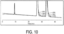
- FIG. 9 and FIG. 10 illustrate, for comparison of the degree of a foot at a peak end portion of each of the chromatograms obtained, the chromatograms displayed superimposed one another, with the peak start and peak end of each chromatogram being enlarged.
- FIG. 9 The results in FIG. 9 indicate that no foot was generated at the peak end portion in FIGS. 7A to 7C in which the column tubes produced in Examples were used as the column bodies. In contrast, a foot was generated at the peak end portion in FIGS. 8A and 8B in which the column tubes produced in Comparative Examples were used as the column bodies ( FIG. 10 ).
Landscapes
- Chemical & Material Sciences (AREA)
- Analytical Chemistry (AREA)
- Chemical Kinetics & Catalysis (AREA)
- Physics & Mathematics (AREA)
- Health & Medical Sciences (AREA)
- Life Sciences & Earth Sciences (AREA)
- Biochemistry (AREA)
- General Health & Medical Sciences (AREA)
- General Physics & Mathematics (AREA)
- Immunology (AREA)
- Pathology (AREA)
- Treatment Of Liquids With Adsorbents In General (AREA)
Abstract
Description
- The present invention relates to a novel column tube for chromatography, and a column for chromatography employing the same.
- A chromatograph such as a liquid chromatograph or a supercritical fluid chromatograph typically includes a column tube including a separating agent (stationary phase) for separating components to be separated, the components having been introduced into a fluid as a mobile phase.
- In the related art, for column tubes that are used in chromatographs, during a process of manufacturing the same, polishing of an inner surface of the tube is omitted, or a method of polishing with no directionality is used, in which the inner surface of the tube is uniformly polished as in electropolishing, or a method is used, in which buffing is performed in a circumferential direction of the tube.
- In addition to these methods, a method referred to as honing is well known, in which an inner circumferential surface of a tube material is polished by polishing processing implemented in a combination of a rotating motion and a reciprocating motion.
- In addition, it is commonly known in this technical field that the surface of an inner circumferential surface of a column tube has to be as smooth as possible (Patent Document 1).
- Patent Document 1:
JP 09-119924 A - In the above-described chromatograph using a known column tube that is not polished or that is polished by using an already available method, a resulting chromatogram contains a long-lasting peak-shape abnormality, which is located near the end of a peak and referred to as a foot (see
FIG. 1 ). - This phenomenon is significantly exhibited particularly in a case where a known column tube is used as a sorting column. For prevention of this phenomenon, arranging, for example, distribution plates, such as porous plate members, at both end portions of the column tube has been studied. However, a complete solution has not been made.
- An object of the present invention is to provide a column tube for chromatography that can prevent a peak shape abnormality referred to as a foot in a resulting chromatogram.
- As a result of intensive research, the present inventors have found that the object described above can be accomplished by a column tube for chromatography including, on an inner circumferential surface thereof, a plurality of polishing traces extending in a flow direction of a fluid.
- Embodiments of the present invention may include the following.
- [1] A column tube for chromatography, through which a fluid flows, the column tube including a plurality of polishing traces extending in a flow direction of the fluid, on an inner circumferential surface of the column tube.
- [2] The column tube for chromatography according to
claim 1, wherein the polishing traces extending in the flow direction of the fluid extend at an angle of 30° or less with respect to the flow direction of the fluid. - [3] The column tube for chromatography according to claim 1 or 2, wherein the polishing traces extending in the flow direction of the fluid exist over an area that accounts for 90% or higher of a total area of the inner circumferential surface.
- [4] The column tube for chromatography according to any one of [1] to [3], wherein a ratio, to a total number of polishing traces, of a number of polishing traces having a depth in a range from 0.01 to 50 µm and a width in a range from 0.01 to 100 µm is 70% or higher.
- [5] The column tube for chromatography according to any one of [1] to [4], wherein the number of polishing traces extending in the flow direction of the fluid is equal to or higher than 90% of the total number of polishing traces.
- [6] The column tube for chromatography according to any one of [1] to [5], wherein an inner diameter is from 0.7 to 200 mm.
- [7] A column for chromatography including: the column tube according to any one of [1] to [6]; and a separating agent filled inside the column tube.
- [8] The column for chromatography according to [7], further including a connector configured to connect the column tube and tubing, through which the fluid flows.
- [9] The column for chromatography according to [8], wherein the column for chromatography is used for high performance liquid chromatography or supercritical fluid chromatography.
- [10] A method for manufacturing a column tube for chromatography, the method including providing polishing traces to an inner circumferential surface of a tube material in a longitudinal axial direction of the tube material by inserting a polishing shaft rod having a polishing member into the tube material and reciprocating the tube material.
- A column tube for chromatography can be provided that can prevent a peak shape abnormality referred to as a foot.
-
-
FIG. 1 is a diagram illustrating a peak shape abnormality (foot) observed in a case where a known column tube is used. -
FIG. 2 is a diagram schematically illustrating an aspect of polishing traces extending in a flow direction of a fluid in a column tube (longitudinal axial direction). -
FIG. 3A is a schematic diagram illustrating an aspect of polishing traces present on an inner circumferential surface of the column tube. -
FIG. 3B is a schematic diagram illustrating another aspect of polishing traces present on the inner circumferential surface of the column tube. -
FIG. 4 is a diagram illustrating an example of an aspect of connection between the column tube and tubing, through which the fluid flows. -
FIG. 5 is a diagram illustrating another example of the aspect of connection between the column tube and the tubing through, which the fluid flows. -
FIG. 6A is a diagram illustrating an SEM image (photograph) of an inner circumferential surface of a column tube produced in Example 1 (all 500% magnification). -
FIG. 6B is a diagram illustrating an SEM image (photograph) of an inner circumferential surface of a column tube produced in Example 2 (500% magnification). -
FIG. 6C is a diagram illustrating an SEM image (photograph) of an inner circumferential surface of a column tube produced in Example 3 (500% magnification). -
FIG. 6D is a diagram illustrating an SEM image (photograph) of an inner circumferential surface of the column tube produced in Comparative Example 1 (500% magnification). -
FIG. 6E is a diagram illustrating an SEM image (photograph) of an inner circumferential surface of a column tube produced in Comparative Example 2 (500% magnification). -
FIG. 7A is a chromatogram obtained by using a column produced using the column tube in Example 1. -
FIG. 7B is a chromatogram obtained by using a column produced using the column tube in Example 2. -
FIG. 7C is a chromatogram obtained by using a column produced using the column tube in Example 3. -
FIG. 8A is a chromatogram obtained by using a column produced using the column tube in Comparative Example 1. -
FIG. 8B is a chromatogram obtained by using a column produced using the column tube in Comparative Example 2. -
FIG. 9 is a diagram illustrating portions of chromatograms obtained by using the columns produced using the column tubes in Examples, with the portions being enlarged and superimposed one another (7A to 7C in the figure correspond to the drawing numbers). -
FIG. 10 is a diagram illustrating portions of chromatograms obtained by using the columns produced using the column tubes in Examples and Comparative Examples, with the portions being enlarged and superimposed one another (7B, 8A, and 8B in the figure correspond to the drawing numbers). - A column tube for chromatography according to an embodiment of the present invention (also simply referred to as a column tube) includes, on an inner circumferential surface thereof, a plurality of polishing traces extending in a flow direction of a fluid.
- The polishing traces as used herein refer to streak-like polishing traces resulting from mechanical polishing.
- A single polishing trace may have a depth ranging from 0.01 to 50 µm, preferably from 0.05 to 20 µm, and more preferably from 0.1 to 5 µm.
- Additionally, a single polishing trace may have a width ranging from 0.01 to 100 µm, preferably from 0.02 to 80 µm, and more preferably from 0.03 to 50 µm.
- In an aspect of the column tube according to an embodiment of the present invention, on the inner circumferential surface, the ratio, to a total number of polishing traces, of the number of polishing traces having a depth ranging from 0.01 to 50 µm and a width ranging from 0.01 to 100 µm is 70% or higher. The ratio is preferably 80% or higher, and more preferably 85% or higher. The ratio, and the width and depth of the polishing traces can be adjusted by adjusting the roughness of a polishing member that is used when the inner circumferential surface of the column tube is polished and adjusting a period of time for polishing.
- The existence of polishing traces, which have appropriate widths and depths, at a higher percentage on the inner circumferential surface of the column tube contributes to exertion of the effect of the embodiment of the present invention.
- Note that the depth and width of the polishing traces can be obtained by capturing an image of the inner circumferential surface of the column tube using a non-contact surface/layer cross-sectional shape measurement system and processing the image using a computer included in the system.
- On the inner circumferential surface of the column tube according to the embodiment of the present invention, the polishing traces extend in the flow direction of the fluid in the column tube (also referred to as a longitudinal axial direction or simply a vertical direction in a case where the length of the column tube in the flow direction of the fluid is larger than the outer diameter of the column tube). Not only polishing traces extending parallel to (an angle of 0°) the flow direction of the fluid in the column tube but also polishing traces extending at an angle of 30° or less as viewed from the flow direction of the fluid in the column tube are assumed to correspond to the wording "polishing traces extending in the flow direction of the fluid".
- The angle as viewed from the flow direction of the fluid is more preferably 20° or less, and still more preferably 10° or less. These are schematically illustrated in
FIG. 2 . - In the column tube for chromatography of the embodiment of present invention, the polishing traces extending in the flow direction of the fluid preferably exist over an area that accounts for 90% or higher of a total area of the inner circumferential surface of the column tube. The existence of the polishing traces at such a rate on the inner circumferential surface of the column tube contributes to achieving the effect of the present invention. The ratio is more preferably 93% or higher, and still more preferably 95% or higher.
- This is schematically illustrated in
FIG. 3A . InFIG. 3A , the polishing traces extending in the flow direction of the fluid are illustrated as polishing traces 1. - Note that, in this Specification, when area, in which the polishing traces extending in the flow direction of the fluid in the column tube are present, is determined, the following definition is used: i.e., when a 0.2 µm square is observed at any three points on the inner circumferential surface in a case where the number of polishing traces is one or more, the polishing traces are present in the 0.2 µm square.
- In addition, in the column tube for chromatography according to the embodiment of the present invention, the number of the polishing traces extending in the flow direction of the fluid is preferably 90% or higher and more preferably 93% or higher of the number of all the polishing traces including polishing traces that do not extend in the flow direction of the fluid.
- This is schematically illustrated in
FIG. 3B. FIG. 3B illustrates an aspect in which polishing traces extending in the flow direction of the fluid are illustrated as the polishing traces 1 and in which polishing traces 2 exist extending in a direction different from the flow direction of the fluid (the polishing traces 2 exist at an angle higher than 30° with respect to the flow direction of the fluid). - In a process of manufacturing the column tube according to the embodiment of the present invention, in rare cases, polishing traces extending in the flow direction of the fluid in the column tube and polishing traces extending in other directions coexist. In the embodiment of the present invention, as few as possible of such polishing traces exist.
- In this Specification, examples of the chromatography may include high performance liquid chromatography and supercritical fluid chromatography.
- Examples of a material for the column tube may include stainless steel and polyetheretherketone (PEEK).
- A tube material that is made from these materials and manufactured based on a known method can be utilized.
- For example, in a case where the tube material is stainless steel, first, a seamless pipe serving as a raw tube is prepared, and bright annealing, which is a known method, is performed to obtain a BA tube. Then, the tip of the seamless BA tube is squeezed, and the tube is drawn out through a forming member referred to as a dice. Thus, a tube material for a column tube can be obtained.
- In a case where the column tube is made from stainless steel, the tube material obtained via the process described above may be subjected to normal surface treatment, for example, electropolishing or chemical polishing, and the resultant tube material may be used for manufacturing a column tube according to the embodiment of the present invention.
- In a case where the tube material is made from PEEK, a commercially available tube material may be used.
- As for the inner diameter of the column tube for chromatography according to the embodiment of the present invention, a range used in normal chromatography can be employed. For example, the inner diameter may be appropriately set to a range from 0.7 to 200 mm, depending on an intended use, e.g., analysis or sorting. Examples of an upper-limit inner diameter may include 70 mm, and may include 50 mm. Among these in the range, the inner diameter may specifically be, for example, 0.7 mm, 1.0 mm, 1.5 mm, 2.0 mm, 3.0 m, 4.6 mm, 6.0 mm, 10 mm, 20 mm, 30 mm, 50 mm, 100 mm, 150 mm, or 200 mm.
- As for the length of the column tube for chromatography according to the embodiment of the present invention, the same length as that of a column tube used in chromatography may be employed. For example, depending on the intended use, e.g., analysis or sorting, the length may be less than 50 mm, equal to or greater than 50 mm and less than 100 mm, equal to or greater than 100 mm and less than 250 mm, or greater than 250 mm.
- A column tube according to the embodiment of the present invention filled with a separating agent for a target material may be utilized as a column body constituting a chromatographic column for liquid chromatography, supercritical fluid chromatography, or the like.
- The separating agent filled inside the column tube according to the embodiment of the present invention is not particularly limited, and examples of a separating agent include a separating agent used in size exclusion chromatography (SEC), a separating agent used in ion exchange chromatography (anion exchange or cation exchange), a separating agent used in adsorption chromatography, a separating agent used in partition (reverse phase) chromatography, a separating agent for optical isomers, and a separating agent of an inner-surface reverse phase type.
- These separating agents are preferably particulate and typically have a particle diameter from 1 to 20 µm.
- The column tube according to the embodiment of the present invention functions as a column for chromatography by being internally filled with the separating agent as described above. A method for filling the above-described separating agent into the column tube is not limited, and a slurry method, for example, may be used.
- An aspect of the column for chromatography may include connectors provided at both end portions of the column tube and used to connect tubing, through which a fluid serving as a mobile phase flows, with a column tube (column body) internally filled with a separating agent. Alternatively, another aspect of the column tube for chromatography may include filters installed at both end portions of a column tube filled with a separating agent and include no connector as in the case of a cartridge column.
- An example in which connectors are provided at both end portions of a column tube will be described with reference to
FIG. 4 and FIG. 5. FIG. 4 and FIG. 5 each illustrate a typical example, and the embodiment of the present invention is not limited to these examples. -
FIG. 4 is an enlarged view of a portion of an example in which outer surfaces of both end portions of acolumn tube 3 are used without performing any particular processing thereon.Connectors 7 provided at both end portions of thecolumn tube 3 are fixed by being threadably engaged withnuts 4 viaferrules 5 fitted on both end portions of thecolumn tube 3. - As illustrated in
FIG. 4 , afilter 6 may be provided inside each of theconnectors 7. In the aspect inFIG. 4 , in a case where the column body is connected to the tubing, through which a fluid flows, the connection can be achieved by screwing, into theconnector 7, asetscrew 8 through which the tubing is passed. - On the other hand,
FIG. 5 is an enlarged view of a portion of an example in which the outer surfaces of both end portions of the column tube 9 are threaded. Aconnector 10 inFIG. 5 is provided, at one end thereof, with a thread groove threadably engaged with a threaded portion of an end portion of the column tube 9, and, at the other end thereof, with a thread groove threadably engaged with thesetscrew 8. In addition, as in the case ofFIG. 4 , the connector 9 may be provided with afilter 6. In the aspect inFIG. 5 , in a case where the column body is connected to the tubing, through which a fluid flows, the connection may be achieved by screwing thesetscrew 8, through which the tubing is passed, into theconnector 10 threadably engaged with column tube 9. - The method for manufacturing the column tube according to the embodiment of the present invention includes polishing in which a polishing shaft rod having a polishing member is inserted into a tube material used as a raw material, then the tube material is reciprocated, and thus polishing traces are provided to an inner circumferential surface of the tube material in a longitudinal axial direction.
- The tube material used as a raw material may be a tube material for the column tube made from stainless steel, PEEK, or the like described above. The length of the column tube material subjected to the above-described process may be approximately 1m, but may not be limited to such a length. In addition, the tube material used as a raw material may be subjected to surface treatment such as electropolishing or chemical polishing.
- The polishing member of the polishing shaft rod is not particularly limited, and may be a buff including, on a surface thereof, a polishing agent.
- Conditions for reciprocation of the tube material are not particularly limited as long as the polishing traces described above are provided to the inner circumferential surface.
- Examples of an apparatus used to perform the above-described process include an apparatus described in
JP 56-121553 - The document does not describe the concept that the tube material is simply reciprocated to polish the inner circumferential surface thereof, in other words, the inner surface of the tube member is polished only in the longitudinal axial direction, to provide polishing traces to the inner circumferential surface in the longitudinal axial direction.
- In addition, the above-described document describes a need to smoothly finish the inner circumferential surface of the tube material, and this clearly differs from the concept of the present invention.
- The method for manufacturing the column tube according to the embodiment of the present invention may include: after the above-described polishing, severing in which, for example, the column tube is severed into an appropriate length depending on the intended use of the column; cutting such as performing threading on the resulting column tube; and then finishing such as performing cleaning to bring the column tube into a state appropriate as a product.
- Examples will be described below, but the present invention is not limited to these examples.
- A commercially available stainless steel column tube (inner diameter: 20 mm, length: 1000 mm) was prepared.
- A polishing device including a polishing shaft rod was used, with this polishing shaft rod including, at the tip thereof, a polishing member (abacus beads with sandpaper attached thereto). The polishing shaft rod was inserted into the stainless steel column tube and reciprocated, thereby producing a column tube having polishing traces provided to the inner circumferential surface of the stainless steel column tube. The column tube was severed into a length of 250 mm.
- By the above-described operation, the polishing traces were formed on the inner circumferential surface of the column tube along the longitudinal direction (the flow direction of a fluid) of the column tube (vertical polishing).
- Three types of column tubes were produced with sandpaper of various surface roughness (Example 1: #300, Example 2: #400, and Example 3: #600).
FIGS. 6A to 6C illustrate photographs of the inner circumferential surfaces of the column tubes in Examples 1 to 3 taken with a scanning electron microscope (500% magnification). - In each of the column tubes obtained in Examples 1 to 3, the polishing traces extending in the longitudinal axial direction of the column tube accounted for approximately 95% or higher (Example 1), approximately 95% or higher (Example 2), approximately 95% or higher (Example 3) of the total area of the inner circumferential surface of the column tube.
- In addition, a ratio, to the total number of polishing traces, of the number of polishing traces having a depth in a range from 0.01 to 50 µm and a width in a range from 0.01 to 100 µm was approximately 95% or higher (Example 1), approximately 95% or higher (Example 2), and approximately 95% or higher (Example 3).
- The number of polishing traces extending in the longitudinal axial direction was approximately 95% or higher (Example 1), approximately 95% or higher (Example 2), and approximately 95% or higher (Example 3) of the total number of polishing traces.
- The polishing shaft rod of the above-described polishing device was inserted into the commercially available stainless steel column tube prepared in Example 1. The polishing shaft rod was then rotated in the direction (circumferential direction of the stainless steel tube) orthogonal to the insertion direction of the shaft rod, whereby the stainless steel column tube having polishing traces provided to the inner circumferential surface thereof was produced.
- By the above-described operation, the polishing traces were formed on the inner circumferential surface of the column tube along the circumferential direction (direction orthogonal to the flow direction of a fluid) of the column tube (lateral polishing).
FIG. 6D illustrates a photograph of the inner circumferential surface of the column tube in Comparative Example 1, taken with a scanning electron microscope (500% magnification). - The polishing shaft rod of the above-described polishing device was inserted into the commercially available stainless steel column tube prepared in Example 1. The polishing shaft rod was then rotated in the direction (circumferential direction of the stainless steel tube) orthogonal to the insertion direction of the shaft rod and reciprocated in the insertion direction, whereby the stainless steel column tube having polishing traces provided to the inner circumferential surface of the column tube was produced.
- By the above-described operation, polishing traces were formed on the inner circumferential surface of the column tube, with these polishing traces extending obliquely with respect to the flow direction of the fluid in the column tube (longitudinal direction) and the circumferential direction of the column tube (honing).
FIG. 6E illustrates a photograph of the inner circumferential surface of the column tube in Comparative Example 2, taken with a scanning electron microscope (500% magnification). - Additionally, the depth and width of each of the polishing traces were measured from an SEM image of the inner circumferential surface of each column tube. The results are indicated in Table 1.
-
Table 1 Depth (µm) Width (µm) Example 1 0.5 50 Example 2 0.5 10 to 20 Example 3 0.5 5 to 10 Comparative Example 1 0.8 5 to 10 Comparative Example 2 0.3 5 to 10 - Each of the column tubes produced as described above was employed as a column body to be filled with a separating agent for high performance liquid chromatography.
- The column body was internally filled with (CHIRALCEL OJ-H, particle size: 5 µm) as a separating agent by a slurry method, and a ferrule and a nut were placed at both ends (liquid inlet and liquid outlet) of the column body. An end connector to be threadably engaged with the nut was threadably engaged with the nut, whereby a column for high performance liquid chromatography was produced.
- Tests were performed in which each of the columns produced as described above was used to separate a test sample (trans-Stilbene oxide) by high performance liquid chromatography.
Conditions for high performance liquid chromatography are as follows.
Eluant: n-hexane/2-propanol = 90/10
Flow rate: 6.0 mL/min.
Column temperature: 25°C
Detector: 254 nm - The samples were separated by using each of the produced columns for the high performance liquid chromatography. Resulting chromatograms are illustrated in
FIG. 7 andFIG. 8 .FIG. 7 illustrates chromatograms for columns using the column tubes produced in Example 1 to 3, andFIG. 8 illustrates chromatograms for columns using the column tubes produced in Comparative Examples 1 and 2. - In addition,
FIG. 9 andFIG. 10 illustrate, for comparison of the degree of a foot at a peak end portion of each of the chromatograms obtained, the chromatograms displayed superimposed one another, with the peak start and peak end of each chromatogram being enlarged. - The results in
FIG. 9 indicate that no foot was generated at the peak end portion inFIGS. 7A to 7C in which the column tubes produced in Examples were used as the column bodies. In contrast, a foot was generated at the peak end portion inFIGS. 8A and 8B in which the column tubes produced in Comparative Examples were used as the column bodies (FIG. 10 ).
Claims (10)
- A column tube for chromatography, through which a fluid flows,
the column tube comprising a plurality of polishing traces extending in a flow direction of the fluid, on an inner circumferential surface of the column tube. - The column tube for chromatography according to claim 1, wherein the polishing traces extending in the flow direction of the fluid extend at an angle of 30° or less with respect to the flow direction of the fluid.
- The column tube for chromatography according to claim 1 or 2, wherein the polishing traces extending in the flow direction of the fluid exist over an area that accounts for 90% or higher of a total area of the inner circumferential surface.
- The column tube for chromatography according to any one of claims 1 to 3, wherein a ratio, to a total number of polishing traces, of a number of polishing traces having a depth in a range from 0.01 to 50 µm and a width in a range from 0.01 to 100 µm is 70% or higher.
- The column tube for chromatography according to any one of claims 1 to 4, wherein the number of polishing traces extending in the flow direction of the fluid is equal to or more than 90% of the total number of polishing traces.
- The column tube for chromatography according to any one of claims 1 to 5, which has an inner diameter from 0.7 to 200 mm.
- A column for chromatography comprising:the column tube according to any one of claims 1 to 6; anda separating agent filled inside the column tube.
- The column for chromatography according to claim 7, further comprising a connector configured to connect the column tube and tubing, through which the fluid flows.
- The column for chromatography according to claim 7 or 8, wherein the column for chromatography is used for high performance liquid chromatography or supercritical fluid chromatography.
- A method for manufacturing a column tube for chromatography,
the method comprising providing polishing traces to an inner circumferential surface of a tube material in a longitudinal axial direction of the tube material by inserting a polishing shaft rod having a polishing member into the tube material and reciprocating the tube material.
Applications Claiming Priority (2)
| Application Number | Priority Date | Filing Date | Title |
|---|---|---|---|
| JP2017097355 | 2017-05-16 | ||
| PCT/JP2018/018711 WO2018212165A1 (en) | 2017-05-16 | 2018-05-15 | Column tube for chromatography, and column for chromatography employing same |
Publications (3)
| Publication Number | Publication Date |
|---|---|
| EP3627151A1 true EP3627151A1 (en) | 2020-03-25 |
| EP3627151A4 EP3627151A4 (en) | 2020-05-20 |
| EP3627151B1 EP3627151B1 (en) | 2023-07-05 |
Family
ID=64273819
Family Applications (1)
| Application Number | Title | Priority Date | Filing Date |
|---|---|---|---|
| EP18802540.7A Active EP3627151B1 (en) | 2017-05-16 | 2018-05-15 | Column tube for chromatography and its use |
Country Status (6)
| Country | Link |
|---|---|
| US (1) | US11529569B2 (en) |
| EP (1) | EP3627151B1 (en) |
| JP (1) | JP7041132B2 (en) |
| KR (1) | KR102604606B1 (en) |
| CN (1) | CN110621995B (en) |
| WO (1) | WO2018212165A1 (en) |
Family Cites Families (17)
| Publication number | Priority date | Publication date | Assignee | Title |
|---|---|---|---|---|
| DE2315904C3 (en) * | 1973-03-30 | 1975-09-11 | Istvan Prof. Dr. 6600 Saarbruecken Halasz | Packed chromatographic separation column |
| JPS5236034B2 (en) * | 1973-12-19 | 1977-09-13 | ||
| JPS56121553A (en) | 1980-02-27 | 1981-09-24 | Olympus Optical Co | Injection type freezing treatment tool |
| US5055402A (en) * | 1989-01-04 | 1991-10-08 | Bio-Recovery Systems, Inc. | Removal of metal ions with immobilized metal ion-binding microorganisms |
| JPH0669487B2 (en) | 1991-02-15 | 1994-09-07 | 東京大学長 | Method for promoting and controlling biological cell growth and functional differentiation |
| JPH09119924A (en) | 1995-08-01 | 1997-05-06 | Hewlett Packard Co <Hp> | Separating column for chromatography |
| JP4319725B2 (en) * | 1999-02-17 | 2009-08-26 | 信越石英株式会社 | Quartz glass cylindrical inner surface polishing equipment |
| US6207049B1 (en) * | 1999-07-30 | 2001-03-27 | Agilent Technologies, Inc. | Multichannel capillary column |
| GB0801127D0 (en) | 2008-01-22 | 2008-02-27 | Ge Healthcare Bio Sciences Ab | Method for removing air from a chromatography column |
| KR200446840Y1 (en) * | 2008-03-24 | 2009-12-03 | (주)유브이플러스 | Manual cleaning device for quartz tube of ultraviolet sterilizer |
| JP2010107389A (en) * | 2008-10-30 | 2010-05-13 | Shimadzu Corp | Autosampler |
| US8828514B2 (en) * | 2010-02-26 | 2014-09-09 | Sumitomo Electric Fine Polymer, Inc. | Fluororesin tube and rotary member for fixing device |
| CN102175803A (en) * | 2011-01-28 | 2011-09-07 | 中国科学院生物物理研究所 | Counter-current chromatograph and special counter-current chromatographic column thereof |
| US20150024152A1 (en) * | 2013-07-19 | 2015-01-22 | Agilent Technologies, Inc. | Metal components with inert vapor phase coating on internal surfaces |
| US10073068B2 (en) | 2013-09-18 | 2018-09-11 | Agilent Technologies, Inc. | Liquid chromatography columns with structured walls |
| CN105126387B (en) * | 2015-09-11 | 2017-01-25 | 电子科技大学 | Wave-shaped miniature gas chromatography column and preparation method thereof |
| WO2017104747A1 (en) * | 2015-12-16 | 2017-06-22 | 株式会社 潤工社 | Column |
-
2018
- 2018-05-15 KR KR1020197034844A patent/KR102604606B1/en active Active
- 2018-05-15 CN CN201880031058.9A patent/CN110621995B/en active Active
- 2018-05-15 US US16/614,156 patent/US11529569B2/en active Active
- 2018-05-15 JP JP2019518796A patent/JP7041132B2/en active Active
- 2018-05-15 EP EP18802540.7A patent/EP3627151B1/en active Active
- 2018-05-15 WO PCT/JP2018/018711 patent/WO2018212165A1/en not_active Ceased
Also Published As
| Publication number | Publication date |
|---|---|
| KR20200004336A (en) | 2020-01-13 |
| KR102604606B1 (en) | 2023-11-22 |
| EP3627151B1 (en) | 2023-07-05 |
| EP3627151A4 (en) | 2020-05-20 |
| US11529569B2 (en) | 2022-12-20 |
| CN110621995B (en) | 2021-12-28 |
| CN110621995A (en) | 2019-12-27 |
| WO2018212165A1 (en) | 2018-11-22 |
| US20200070065A1 (en) | 2020-03-05 |
| JPWO2018212165A1 (en) | 2020-03-26 |
| JP7041132B2 (en) | 2022-03-23 |
Similar Documents
| Publication | Publication Date | Title |
|---|---|---|
| Wikström et al. | Immobilisation and evaluation of a vancomycin chiral stationary phase for capillary electrochromatography | |
| Bruns et al. | Influence of particle properties on the wall region in packed capillaries | |
| Marcus et al. | Capillary-channeled polymer fibers as stationary phases in liquid chromatography separations | |
| US20140306105A1 (en) | Liquid chromatrography systems and methods | |
| US20110049030A1 (en) | Chromatography Column With Large Diameter End Fitting Openings | |
| JP7055539B2 (en) | Performance monitoring in continuous chromatography | |
| EP3829733B1 (en) | Liquid chromatography/mass spectrometry methods for the analysis of polar molecules | |
| US20040238447A1 (en) | Stainless steel tubing/frit with sintered inorganic particle, the chromatography comprising it, and their manufacturing method | |
| Close et al. | Fouling of an anion exchange chromatography operation in a monoclonal antibody process: visualization and kinetic studies | |
| EP3627151B1 (en) | Column tube for chromatography and its use | |
| CN106413993A (en) | Abrasive grain-fixed wire, wire saw, and method for cutting workpiece | |
| JP2017517012A (en) | Sample extraction device with fine elution bed design | |
| DE112005000518T5 (en) | Frit for high pressure liquid chromatography | |
| US10718743B2 (en) | Liquid chromatography columns with structured walls | |
| Koreshkova et al. | Recent advances and applications of synthetic diamonds in solid-phase extraction and high-performance liquid chromatography | |
| DE112005002008B4 (en) | Device and apparatus for performing separations | |
| US20070102358A1 (en) | Solid phase extraction column | |
| US5449461A (en) | Displacement countercurrent chromatography | |
| EP3059585A1 (en) | Method for manufacturing small-diameter column for chromatography | |
| JP5521218B2 (en) | Liquid chromatograph filter | |
| JPWO2000029843A1 (en) | Diffusion enhancer for slow flow gradient high-performance liquid chromatography. | |
| EP1154826A1 (en) | End piece for monolithic chromatography columns | |
| Kamour et al. | Development of fused-core silica HPLC columns and their recent pharmaceutical and biological applications: a review | |
| WO2009151091A1 (en) | Method for examination of alzheimer’s disease | |
| Patil et al. | A review on UHPLC method |
Legal Events
| Date | Code | Title | Description |
|---|---|---|---|
| STAA | Information on the status of an ep patent application or granted ep patent |
Free format text: STATUS: THE INTERNATIONAL PUBLICATION HAS BEEN MADE |
|
| PUAI | Public reference made under article 153(3) epc to a published international application that has entered the european phase |
Free format text: ORIGINAL CODE: 0009012 |
|
| STAA | Information on the status of an ep patent application or granted ep patent |
Free format text: STATUS: REQUEST FOR EXAMINATION WAS MADE |
|
| 17P | Request for examination filed |
Effective date: 20191205 |
|
| AK | Designated contracting states |
Kind code of ref document: A1 Designated state(s): AL AT BE BG CH CY CZ DE DK EE ES FI FR GB GR HR HU IE IS IT LI LT LU LV MC MK MT NL NO PL PT RO RS SE SI SK SM TR |
|
| AX | Request for extension of the european patent |
Extension state: BA ME |
|
| A4 | Supplementary search report drawn up and despatched |
Effective date: 20200420 |
|
| RIC1 | Information provided on ipc code assigned before grant |
Ipc: G01N 30/02 20060101ALI20200414BHEP Ipc: G01N 30/60 20060101AFI20200414BHEP Ipc: B01D 15/40 20060101ALI20200414BHEP Ipc: B01D 15/22 20060101ALI20200414BHEP |
|
| DAV | Request for validation of the european patent (deleted) | ||
| DAX | Request for extension of the european patent (deleted) | ||
| GRAP | Despatch of communication of intention to grant a patent |
Free format text: ORIGINAL CODE: EPIDOSNIGR1 |
|
| STAA | Information on the status of an ep patent application or granted ep patent |
Free format text: STATUS: GRANT OF PATENT IS INTENDED |
|
| INTG | Intention to grant announced |
Effective date: 20221214 |
|
| GRAS | Grant fee paid |
Free format text: ORIGINAL CODE: EPIDOSNIGR3 |
|
| GRAA | (expected) grant |
Free format text: ORIGINAL CODE: 0009210 |
|
| STAA | Information on the status of an ep patent application or granted ep patent |
Free format text: STATUS: THE PATENT HAS BEEN GRANTED |
|
| AK | Designated contracting states |
Kind code of ref document: B1 Designated state(s): AL AT BE BG CH CY CZ DE DK EE ES FI FR GB GR HR HU IE IS IT LI LT LU LV MC MK MT NL NO PL PT RO RS SE SI SK SM TR |
|
| REG | Reference to a national code |
Ref country code: CH Ref legal event code: EP |
|
| REG | Reference to a national code |
Ref country code: AT Ref legal event code: REF Ref document number: 1585295 Country of ref document: AT Kind code of ref document: T Effective date: 20230715 |
|
| REG | Reference to a national code |
Ref country code: DE Ref legal event code: R096 Ref document number: 602018052917 Country of ref document: DE |
|
| REG | Reference to a national code |
Ref country code: IE Ref legal event code: FG4D |
|
| REG | Reference to a national code |
Ref country code: LT Ref legal event code: MG9D |
|
| REG | Reference to a national code |
Ref country code: NL Ref legal event code: MP Effective date: 20230705 |
|
| REG | Reference to a national code |
Ref country code: AT Ref legal event code: MK05 Ref document number: 1585295 Country of ref document: AT Kind code of ref document: T Effective date: 20230705 |
|
| PG25 | Lapsed in a contracting state [announced via postgrant information from national office to epo] |
Ref country code: NL Free format text: LAPSE BECAUSE OF FAILURE TO SUBMIT A TRANSLATION OF THE DESCRIPTION OR TO PAY THE FEE WITHIN THE PRESCRIBED TIME-LIMIT Effective date: 20230705 |
|
| PG25 | Lapsed in a contracting state [announced via postgrant information from national office to epo] |
Ref country code: GR Free format text: LAPSE BECAUSE OF FAILURE TO SUBMIT A TRANSLATION OF THE DESCRIPTION OR TO PAY THE FEE WITHIN THE PRESCRIBED TIME-LIMIT Effective date: 20231006 |
|
| PG25 | Lapsed in a contracting state [announced via postgrant information from national office to epo] |
Ref country code: ES Free format text: LAPSE BECAUSE OF FAILURE TO SUBMIT A TRANSLATION OF THE DESCRIPTION OR TO PAY THE FEE WITHIN THE PRESCRIBED TIME-LIMIT Effective date: 20230705 |
|
| PG25 | Lapsed in a contracting state [announced via postgrant information from national office to epo] |
Ref country code: IS Free format text: LAPSE BECAUSE OF FAILURE TO SUBMIT A TRANSLATION OF THE DESCRIPTION OR TO PAY THE FEE WITHIN THE PRESCRIBED TIME-LIMIT Effective date: 20231105 |
|
| PG25 | Lapsed in a contracting state [announced via postgrant information from national office to epo] |
Ref country code: SE Free format text: LAPSE BECAUSE OF FAILURE TO SUBMIT A TRANSLATION OF THE DESCRIPTION OR TO PAY THE FEE WITHIN THE PRESCRIBED TIME-LIMIT Effective date: 20230705 Ref country code: RS Free format text: LAPSE BECAUSE OF FAILURE TO SUBMIT A TRANSLATION OF THE DESCRIPTION OR TO PAY THE FEE WITHIN THE PRESCRIBED TIME-LIMIT Effective date: 20230705 Ref country code: PT Free format text: LAPSE BECAUSE OF FAILURE TO SUBMIT A TRANSLATION OF THE DESCRIPTION OR TO PAY THE FEE WITHIN THE PRESCRIBED TIME-LIMIT Effective date: 20231106 Ref country code: NO Free format text: LAPSE BECAUSE OF FAILURE TO SUBMIT A TRANSLATION OF THE DESCRIPTION OR TO PAY THE FEE WITHIN THE PRESCRIBED TIME-LIMIT Effective date: 20231005 Ref country code: LV Free format text: LAPSE BECAUSE OF FAILURE TO SUBMIT A TRANSLATION OF THE DESCRIPTION OR TO PAY THE FEE WITHIN THE PRESCRIBED TIME-LIMIT Effective date: 20230705 Ref country code: LT Free format text: LAPSE BECAUSE OF FAILURE TO SUBMIT A TRANSLATION OF THE DESCRIPTION OR TO PAY THE FEE WITHIN THE PRESCRIBED TIME-LIMIT Effective date: 20230705 Ref country code: IS Free format text: LAPSE BECAUSE OF FAILURE TO SUBMIT A TRANSLATION OF THE DESCRIPTION OR TO PAY THE FEE WITHIN THE PRESCRIBED TIME-LIMIT Effective date: 20231105 Ref country code: HR Free format text: LAPSE BECAUSE OF FAILURE TO SUBMIT A TRANSLATION OF THE DESCRIPTION OR TO PAY THE FEE WITHIN THE PRESCRIBED TIME-LIMIT Effective date: 20230705 Ref country code: GR Free format text: LAPSE BECAUSE OF FAILURE TO SUBMIT A TRANSLATION OF THE DESCRIPTION OR TO PAY THE FEE WITHIN THE PRESCRIBED TIME-LIMIT Effective date: 20231006 Ref country code: FI Free format text: LAPSE BECAUSE OF FAILURE TO SUBMIT A TRANSLATION OF THE DESCRIPTION OR TO PAY THE FEE WITHIN THE PRESCRIBED TIME-LIMIT Effective date: 20230705 Ref country code: ES Free format text: LAPSE BECAUSE OF FAILURE TO SUBMIT A TRANSLATION OF THE DESCRIPTION OR TO PAY THE FEE WITHIN THE PRESCRIBED TIME-LIMIT Effective date: 20230705 Ref country code: AT Free format text: LAPSE BECAUSE OF FAILURE TO SUBMIT A TRANSLATION OF THE DESCRIPTION OR TO PAY THE FEE WITHIN THE PRESCRIBED TIME-LIMIT Effective date: 20230705 |
|
| PG25 | Lapsed in a contracting state [announced via postgrant information from national office to epo] |
Ref country code: PL Free format text: LAPSE BECAUSE OF FAILURE TO SUBMIT A TRANSLATION OF THE DESCRIPTION OR TO PAY THE FEE WITHIN THE PRESCRIBED TIME-LIMIT Effective date: 20230705 |
|
| REG | Reference to a national code |
Ref country code: DE Ref legal event code: R097 Ref document number: 602018052917 Country of ref document: DE |
|
| PG25 | Lapsed in a contracting state [announced via postgrant information from national office to epo] |
Ref country code: SM Free format text: LAPSE BECAUSE OF FAILURE TO SUBMIT A TRANSLATION OF THE DESCRIPTION OR TO PAY THE FEE WITHIN THE PRESCRIBED TIME-LIMIT Effective date: 20230705 Ref country code: RO Free format text: LAPSE BECAUSE OF FAILURE TO SUBMIT A TRANSLATION OF THE DESCRIPTION OR TO PAY THE FEE WITHIN THE PRESCRIBED TIME-LIMIT Effective date: 20230705 Ref country code: EE Free format text: LAPSE BECAUSE OF FAILURE TO SUBMIT A TRANSLATION OF THE DESCRIPTION OR TO PAY THE FEE WITHIN THE PRESCRIBED TIME-LIMIT Effective date: 20230705 Ref country code: DK Free format text: LAPSE BECAUSE OF FAILURE TO SUBMIT A TRANSLATION OF THE DESCRIPTION OR TO PAY THE FEE WITHIN THE PRESCRIBED TIME-LIMIT Effective date: 20230705 Ref country code: CZ Free format text: LAPSE BECAUSE OF FAILURE TO SUBMIT A TRANSLATION OF THE DESCRIPTION OR TO PAY THE FEE WITHIN THE PRESCRIBED TIME-LIMIT Effective date: 20230705 Ref country code: SK Free format text: LAPSE BECAUSE OF FAILURE TO SUBMIT A TRANSLATION OF THE DESCRIPTION OR TO PAY THE FEE WITHIN THE PRESCRIBED TIME-LIMIT Effective date: 20230705 |
|
| PLBE | No opposition filed within time limit |
Free format text: ORIGINAL CODE: 0009261 |
|
| STAA | Information on the status of an ep patent application or granted ep patent |
Free format text: STATUS: NO OPPOSITION FILED WITHIN TIME LIMIT |
|
| PG25 | Lapsed in a contracting state [announced via postgrant information from national office to epo] |
Ref country code: IT Free format text: LAPSE BECAUSE OF FAILURE TO SUBMIT A TRANSLATION OF THE DESCRIPTION OR TO PAY THE FEE WITHIN THE PRESCRIBED TIME-LIMIT Effective date: 20230705 |
|
| 26N | No opposition filed |
Effective date: 20240408 |
|
| PG25 | Lapsed in a contracting state [announced via postgrant information from national office to epo] |
Ref country code: SI Free format text: LAPSE BECAUSE OF FAILURE TO SUBMIT A TRANSLATION OF THE DESCRIPTION OR TO PAY THE FEE WITHIN THE PRESCRIBED TIME-LIMIT Effective date: 20230705 |
|
| PG25 | Lapsed in a contracting state [announced via postgrant information from national office to epo] |
Ref country code: BG Free format text: LAPSE BECAUSE OF FAILURE TO SUBMIT A TRANSLATION OF THE DESCRIPTION OR TO PAY THE FEE WITHIN THE PRESCRIBED TIME-LIMIT Effective date: 20230705 |
|
| PG25 | Lapsed in a contracting state [announced via postgrant information from national office to epo] |
Ref country code: BG Free format text: LAPSE BECAUSE OF FAILURE TO SUBMIT A TRANSLATION OF THE DESCRIPTION OR TO PAY THE FEE WITHIN THE PRESCRIBED TIME-LIMIT Effective date: 20230705 |
|
| PG25 | Lapsed in a contracting state [announced via postgrant information from national office to epo] |
Ref country code: MC Free format text: LAPSE BECAUSE OF FAILURE TO SUBMIT A TRANSLATION OF THE DESCRIPTION OR TO PAY THE FEE WITHIN THE PRESCRIBED TIME-LIMIT Effective date: 20230705 |
|
| PG25 | Lapsed in a contracting state [announced via postgrant information from national office to epo] |
Ref country code: LU Free format text: LAPSE BECAUSE OF NON-PAYMENT OF DUE FEES Effective date: 20240515 |
|
| PG25 | Lapsed in a contracting state [announced via postgrant information from national office to epo] |
Ref country code: MC Free format text: LAPSE BECAUSE OF FAILURE TO SUBMIT A TRANSLATION OF THE DESCRIPTION OR TO PAY THE FEE WITHIN THE PRESCRIBED TIME-LIMIT Effective date: 20230705 Ref country code: LU Free format text: LAPSE BECAUSE OF NON-PAYMENT OF DUE FEES Effective date: 20240515 |
|
| REG | Reference to a national code |
Ref country code: BE Ref legal event code: MM Effective date: 20240531 |
|
| PG25 | Lapsed in a contracting state [announced via postgrant information from national office to epo] |
Ref country code: IE Free format text: LAPSE BECAUSE OF NON-PAYMENT OF DUE FEES Effective date: 20240515 |
|
| PG25 | Lapsed in a contracting state [announced via postgrant information from national office to epo] |
Ref country code: BE Free format text: LAPSE BECAUSE OF NON-PAYMENT OF DUE FEES Effective date: 20240531 |
|
| PGFP | Annual fee paid to national office [announced via postgrant information from national office to epo] |
Ref country code: DE Payment date: 20250521 Year of fee payment: 8 |
|
| PGFP | Annual fee paid to national office [announced via postgrant information from national office to epo] |
Ref country code: GB Payment date: 20250527 Year of fee payment: 8 |
|
| PGFP | Annual fee paid to national office [announced via postgrant information from national office to epo] |
Ref country code: FR Payment date: 20250528 Year of fee payment: 8 |
|
| PGFP | Annual fee paid to national office [announced via postgrant information from national office to epo] |
Ref country code: CH Payment date: 20250601 Year of fee payment: 8 |
|
| PG25 | Lapsed in a contracting state [announced via postgrant information from national office to epo] |
Ref country code: CY Free format text: LAPSE BECAUSE OF FAILURE TO SUBMIT A TRANSLATION OF THE DESCRIPTION OR TO PAY THE FEE WITHIN THE PRESCRIBED TIME-LIMIT; INVALID AB INITIO Effective date: 20180515 |
|
| PG25 | Lapsed in a contracting state [announced via postgrant information from national office to epo] |
Ref country code: HU Free format text: LAPSE BECAUSE OF FAILURE TO SUBMIT A TRANSLATION OF THE DESCRIPTION OR TO PAY THE FEE WITHIN THE PRESCRIBED TIME-LIMIT; INVALID AB INITIO Effective date: 20180515 |