EP3627034A1 - Valve - Google Patents
Valve Download PDFInfo
- Publication number
- EP3627034A1 EP3627034A1 EP18461610.0A EP18461610A EP3627034A1 EP 3627034 A1 EP3627034 A1 EP 3627034A1 EP 18461610 A EP18461610 A EP 18461610A EP 3627034 A1 EP3627034 A1 EP 3627034A1
- Authority
- EP
- European Patent Office
- Prior art keywords
- actuating
- valve
- gas
- membrane
- cartridge
- Prior art date
- Legal status (The legal status is an assumption and is not a legal conclusion. Google has not performed a legal analysis and makes no representation as to the accuracy of the status listed.)
- Granted
Links
Images



Classifications
-
- F—MECHANICAL ENGINEERING; LIGHTING; HEATING; WEAPONS; BLASTING
- F16—ENGINEERING ELEMENTS AND UNITS; GENERAL MEASURES FOR PRODUCING AND MAINTAINING EFFECTIVE FUNCTIONING OF MACHINES OR INSTALLATIONS; THERMAL INSULATION IN GENERAL
- F16K—VALVES; TAPS; COCKS; ACTUATING-FLOATS; DEVICES FOR VENTING OR AERATING
- F16K17/00—Safety valves; Equalising valves, e.g. pressure relief valves
- F16K17/40—Safety valves; Equalising valves, e.g. pressure relief valves with a fracturing member, e.g. fracturing diaphragm, glass, fusible joint
- F16K17/403—Safety valves; Equalising valves, e.g. pressure relief valves with a fracturing member, e.g. fracturing diaphragm, glass, fusible joint with a fracturing valve member
-
- F—MECHANICAL ENGINEERING; LIGHTING; HEATING; WEAPONS; BLASTING
- F16—ENGINEERING ELEMENTS AND UNITS; GENERAL MEASURES FOR PRODUCING AND MAINTAINING EFFECTIVE FUNCTIONING OF MACHINES OR INSTALLATIONS; THERMAL INSULATION IN GENERAL
- F16K—VALVES; TAPS; COCKS; ACTUATING-FLOATS; DEVICES FOR VENTING OR AERATING
- F16K13/00—Other constructional types of cut-off apparatus; Arrangements for cutting-off
- F16K13/04—Other constructional types of cut-off apparatus; Arrangements for cutting-off with a breakable closure member
-
- F—MECHANICAL ENGINEERING; LIGHTING; HEATING; WEAPONS; BLASTING
- F16—ENGINEERING ELEMENTS AND UNITS; GENERAL MEASURES FOR PRODUCING AND MAINTAINING EFFECTIVE FUNCTIONING OF MACHINES OR INSTALLATIONS; THERMAL INSULATION IN GENERAL
- F16K—VALVES; TAPS; COCKS; ACTUATING-FLOATS; DEVICES FOR VENTING OR AERATING
- F16K31/00—Actuating devices; Operating means; Releasing devices
- F16K31/12—Actuating devices; Operating means; Releasing devices actuated by fluid
- F16K31/122—Actuating devices; Operating means; Releasing devices actuated by fluid the fluid acting on a piston
- F16K31/1221—Actuating devices; Operating means; Releasing devices actuated by fluid the fluid acting on a piston one side of the piston being spring-loaded
-
- F—MECHANICAL ENGINEERING; LIGHTING; HEATING; WEAPONS; BLASTING
- F16—ENGINEERING ELEMENTS AND UNITS; GENERAL MEASURES FOR PRODUCING AND MAINTAINING EFFECTIVE FUNCTIONING OF MACHINES OR INSTALLATIONS; THERMAL INSULATION IN GENERAL
- F16K—VALVES; TAPS; COCKS; ACTUATING-FLOATS; DEVICES FOR VENTING OR AERATING
- F16K31/00—Actuating devices; Operating means; Releasing devices
- F16K31/44—Mechanical actuating means
- F16K31/56—Mechanical actuating means without stable intermediate position, e.g. with snap action
-
- F—MECHANICAL ENGINEERING; LIGHTING; HEATING; WEAPONS; BLASTING
- F17—STORING OR DISTRIBUTING GASES OR LIQUIDS
- F17C—VESSELS FOR CONTAINING OR STORING COMPRESSED, LIQUEFIED OR SOLIDIFIED GASES; FIXED-CAPACITY GAS-HOLDERS; FILLING VESSELS WITH, OR DISCHARGING FROM VESSELS, COMPRESSED, LIQUEFIED, OR SOLIDIFIED GASES
- F17C13/00—Details of vessels or of the filling or discharging of vessels
- F17C13/06—Closures, e.g. cap, breakable member
-
- B—PERFORMING OPERATIONS; TRANSPORTING
- B63—SHIPS OR OTHER WATERBORNE VESSELS; RELATED EQUIPMENT
- B63C—LAUNCHING, HAULING-OUT, OR DRY-DOCKING OF VESSELS; LIFE-SAVING IN WATER; EQUIPMENT FOR DWELLING OR WORKING UNDER WATER; MEANS FOR SALVAGING OR SEARCHING FOR UNDERWATER OBJECTS
- B63C9/00—Life-saving in water
- B63C9/08—Life-buoys, e.g. rings; Life-belts, jackets, suits, or the like
- B63C9/18—Inflatable equipment characterised by the gas-generating or inflation device
- B63C9/19—Arrangements for puncturing gas-generating cartridges
-
- B—PERFORMING OPERATIONS; TRANSPORTING
- B63—SHIPS OR OTHER WATERBORNE VESSELS; RELATED EQUIPMENT
- B63C—LAUNCHING, HAULING-OUT, OR DRY-DOCKING OF VESSELS; LIFE-SAVING IN WATER; EQUIPMENT FOR DWELLING OR WORKING UNDER WATER; MEANS FOR SALVAGING OR SEARCHING FOR UNDERWATER OBJECTS
- B63C9/00—Life-saving in water
- B63C9/24—Arrangements of inflating valves or of controls thereof
-
- B—PERFORMING OPERATIONS; TRANSPORTING
- B64—AIRCRAFT; AVIATION; COSMONAUTICS
- B64D—EQUIPMENT FOR FITTING IN OR TO AIRCRAFT; FLIGHT SUITS; PARACHUTES; ARRANGEMENT OR MOUNTING OF POWER PLANTS OR PROPULSION TRANSMISSIONS IN AIRCRAFT
- B64D25/00—Emergency apparatus or devices, not otherwise provided for
- B64D25/08—Ejecting or escaping means
- B64D25/14—Inflatable escape chutes
-
- F—MECHANICAL ENGINEERING; LIGHTING; HEATING; WEAPONS; BLASTING
- F17—STORING OR DISTRIBUTING GASES OR LIQUIDS
- F17C—VESSELS FOR CONTAINING OR STORING COMPRESSED, LIQUEFIED OR SOLIDIFIED GASES; FIXED-CAPACITY GAS-HOLDERS; FILLING VESSELS WITH, OR DISCHARGING FROM VESSELS, COMPRESSED, LIQUEFIED, OR SOLIDIFIED GASES
- F17C2205/00—Vessel construction, in particular mounting arrangements, attachments or identifications means
- F17C2205/03—Fluid connections, filters, valves, closure means or other attachments
- F17C2205/0302—Fittings, valves, filters, or components in connection with the gas storage device
- F17C2205/0311—Closure means
- F17C2205/032—Closure means pierceable
-
- F—MECHANICAL ENGINEERING; LIGHTING; HEATING; WEAPONS; BLASTING
- F17—STORING OR DISTRIBUTING GASES OR LIQUIDS
- F17C—VESSELS FOR CONTAINING OR STORING COMPRESSED, LIQUEFIED OR SOLIDIFIED GASES; FIXED-CAPACITY GAS-HOLDERS; FILLING VESSELS WITH, OR DISCHARGING FROM VESSELS, COMPRESSED, LIQUEFIED, OR SOLIDIFIED GASES
- F17C2270/00—Applications
- F17C2270/07—Applications for household use
- F17C2270/0736—Capsules, e.g. CO2
-
- F—MECHANICAL ENGINEERING; LIGHTING; HEATING; WEAPONS; BLASTING
- F17—STORING OR DISTRIBUTING GASES OR LIQUIDS
- F17C—VESSELS FOR CONTAINING OR STORING COMPRESSED, LIQUEFIED OR SOLIDIFIED GASES; FIXED-CAPACITY GAS-HOLDERS; FILLING VESSELS WITH, OR DISCHARGING FROM VESSELS, COMPRESSED, LIQUEFIED, OR SOLIDIFIED GASES
- F17C2270/00—Applications
- F17C2270/07—Applications for household use
- F17C2270/0772—Inflation devices, e.g. for rescue vests or tyres
Definitions
- the present disclosure relates to valves, and in particular but not exclusively to inflation valves.
- Inflation valves are used in a wide range of applications, for example in inflating emergency evacuation slide systems for aircraft, life rafts and other inflatable devices.
- the disclosure provides a valve which comprises a valve body comprising an inlet for fluid communication with a space or source containing pressurised gas, and at least one outlet.
- a membrane is arranged between the inlet and the at least one outlet.
- a membrane puncturing element is arranged for movement between a retracted, inoperative position and an extended position in which it punctures the membrane.
- An actuating piston is operatively coupled to the membrane puncturing element for moving the membrane puncturing element between its retracted and its extended positions.
- the actuating piston is received in a piston bore of the valve body.
- the valve further comprises a cartridge receiving chamber for receiving a sealed actuating gas cartridge and a cartridge puncturing device for puncturing the actuating gas cartridge.
- An actuating gas flow passage communicates actuating gas released from the actuating gas cartridge to the actuating piston bore upon puncturing the actuating gas cartridge for moving the actuating piston and thus moving the membrane puncturing element from its retracted to its extended position.
- the actuating gas flow passage may comprise an annular plenum extending around the axis of the actuating piston bore. At least one feed passage may extend from the annular plenum to the actuating piston bore.
- Various embodiments may include a plurality of feed passages circumferentially spaced around the axis of the actuating piston bore.
- the plurality of feed passages may be circumferentially equi-spaced around the axis of the actuating piston bore.
- the actuating piston may be biased into contact with an end of the actuating piston bore by a biasing spring.
- the actuating gas flow passage may enter the actuating piston bore adjacent one end of the actuating piston bore.
- a face of the actuating piston facing the end of the actuating piston bore may be crowned so as to form an annular chamber between the actuating piston and the end of the actuating piston bore and the actuating gas flow passage may be connected to the annular chamber.
- the end of the actuating piston bore may be formed by a plug mounted within an opening of the valve body
- the cartridge receiving chamber may be arranged transversely to the axis of the actuating piston.
- the valve body may be additively manufactured.
- the actuating gas cartridge puncturing device may comprise a spring loaded needle.
- the valve may further comprise an actuating gas cartridge arranged in the cartridge receiving chamber.
- the actuating gas may be carbon dioxide.
- the disclosure also provides an inflation device comprising a valve in accordance with the disclosure and a source of inflating gas, for example a cylinder of inflating gas, coupled to the inlet of the valve.
- a source of inflating gas for example a cylinder of inflating gas
- the disclosure also provides a method of inflating an inflatable device comprising: puncturing a membrane arranged in a flow path between a source of inflating gas and the inflatable device by moving a membrane puncturing element from a retracted, inoperative position, to an extended, rupturing position, the movement of the membrane puncturing element to the extended position being effected by releasing actuating gas from an actuating gas cartridge (into an actuation piston bore which receives an actuating piston to which the membrane puncturing element is operatively coupled.
- an inflation device 2 in accordance with the disclosure comprises a source of inflating gas 4 and an inflation valve 6 mounted to the source of inflating gas 2.
- the source of inflating gas is a cylinder containing pressurised gas, for example carbon dioxide.
- the inflation valve 4 selectively communicates inflation gas from the cylinder 4 to a device (not shown) to be inflated.
- the inflation valve 6 comprises a valve body 8 which in this embodiment is mounted to a neck portion 10 of the inflating gas cylinder 2 by means of a threaded connection 12.
- the valve body 8 comprises an inlet passage 14 having an inlet 15 for fluid communication with the cylinder 4, and at least one outlet passage 16 having an outlet 17, in this embodiment, two outlet passages 16, for fluid communication with the device to be inflated.
- the outlet passages 16 may be connected to the device through respective pipes (not shown) or they may simply exhaust directly into the device.
- the outlet passages 16 may be threaded for connection to hoses or other pipes conducting the inflation gas to the device.
- one of the outlet passages 16 may be plugged to provide just a single outlet for inflation gas.
- the inlet passage 14 and the outlet passages 16 are fluidly connected by passages 18 defined within the valve housing 8 as will be described further below.
- the rupturable membrane 20 is received on a shoulder 22 of the inlet passage 14 and retained in position on the shoulder 22 by an externally threaded annular retainer 24 which engages an internally threaded portion 26 of the inlet passage 14.
- a seal 28, for example an O-ring seal 28 may be received between the shoulder 22 and the rupturable membrane 20.
- the inflation valve 4 further comprises a membrane puncturing element 30.
- the membrane puncturing element 30 is a hollow needle, but in other embodiments, the membrane puncturing element 30 may be a pin, spike or the like.
- the membrane puncturing element 30 is, as will be described further below, arranged for movement between a retracted, inoperative position and an extended position in which it punctures the rupturable membrane 20.
- the membrane puncturing element 30 is coupled to an actuating piston 32 by means of a shaft 34.
- the actuating piston 32 is received in a piston bore 36 defined in the valve housing 8.
- a seal for example an O-ring seal 33 may be provided around the head of the piston 32 to improve sealing of the piston 32 within the piston bore 36.
- the piston shaft 34 extends through a guide channel 38 which opens into an enlarged diameter bore section 40 of the inlet passage 14.
- the passages 18 extend between the bore section 40 and the closed ends of the outlet passages 16.
- the piston 32 is urged upwardly, away from the rupturable membrane 20, by means of a biasing member 42, in this embodiment a coil spring 42.
- a biasing member 42 in this embodiment a coil spring 42.
- One end 44 of the spring 42 may, as shown, be located in an annular groove 46 formed in an upwardly facing surface 48 of the piston bore 36.
- the other end 50 of the spring 42 may, as shown, be received within a recess 52 formed in the lower face 54 of the actuating piston 32.
- the upper surface 56 of the actuating piston 32 is, in this embodiment, domed or crowned, i.e. its central region 58 is raised relative to its peripheral region 60.
- the upper surface 56 may in certain embodiments be generally frustoconical in shape. In other embodiments, the upper surface 56 may be curved or stepped for example.
- the piston bore 36 is closed at its upper end 62 by a plug 64.
- the upper end 62 of the piston bore 36 and the plug may be threaded, as shown.
- a seal ring 66 may also be provided, as shown, between the piston bore 36 and the plug 64.
- the lower surface 68 of the plug 64 is generally planar.
- the actuating piston 32 In the retracted position of the membrane puncturing needle illustrated in Figure 2 , the actuating piston 32 is biased into contact with the lower face 68 of the plug 64.
- the effect of the crowning of the upper surface 56 of the actuating piston 32 is that it creates an annular chamber 70 between the upper surface 56 of the actuating piston 32 and the lower surface 68 of the plug 64.
- This chamber 70 has a maximum height at its periphery, becoming shallower towards the axis B of the actuating piston 32.
- the valve body 8 further comprises an actuating gas cartridge receiving chamber 80.
- the actuating gas receiving chamber 80 is arranged with its longitudinal axis A transversely to the axis B of the actuating piston 32, in particular perpendicular thereto.
- the actuating gas cartridge receiving chamber 80 may be arranged such that its axis A is arranged at another orientation relative to the actuating piston axis B, for example generally parallel thereto.
- the actuating gas cartridge receiving chamber 80 receives an actuating gas cartridge 82.
- This cartridge 82 may be a carbon dioxide cartridge, for example.
- Such cartridges which may comply with standard SAE AS6011, are widely used in inflating devices such as life jackets and are sealed cartridges containing a known mass of gas at a known pressure.
- the cartridge may be a Type II, 12 gram capacity carbon dioxide bullet.
- One end 84 of the actuating gas receiving chamber 80 is closed by a removable plug 86, which allows insertion of the actuating gas cylinder 82 into the actuating gas receiving chamber 80.
- the other end 88 of the actuating gas receiving chamber 80 is closed by an actuating gas cartridge puncturing device 90 which will be discussed further below.
- the actuating gas cartridge 82 is biased towards the plug 86 by a spring 92 acting on a collar 94 which engages around the neck 96 of the actuating gas cartridge 82.
- An actuating gas flow passage 100 is formed through the valve body 8 for communicating actuating gas released from the actuating gas cartridge 82 to the actuating piston bore 36 upon puncturing the actuating gas cartridge 82, so as to move the actuating piston 32 to move the membrane puncturing element needle 30 from its retracted to its extended position.
- the actuating gas flow passage 100 comprises an annular plenum 102 formed around the actuating piston bore 36 and a connecting passage 104 extending between the annular plenum 102 and the actuating gas receiving chamber 80.
- at least one, in this embodiment ten, feed passages 106 extend from the annular plenum 102 to the piston bore 36.
- the feed passages 106 may be circumferentially spaced around the piston bore 36.
- the feed passages 106 are circumferentially equi-spaced around the piston bore 36.
- An advantage of this particular arrangement is that it allows actuating gas to be evenly distributed about the entire periphery of the actuating piston 32, thereby reducing out of axis forces on the actuating piston 32.
- the sum of the cross-section surfaces area of the feed passages shall be not smaller than that of the actuating gas flow passage 100. This helps avoid or mitigates a reduction in the pressure or flow rate of gas into the annular chamber 70.
- the feed passages 106 enter the piston bore 36 at the annular chamber 70 adjacent the upper end 62 of the piston bore.36.
- one end 88 of the actuating gas receiving chamber 80 is closed by an actuating gas cartridge puncturing device 90. Details of this actuating gas cartridge puncturing device 90 can be seen in Figures 4 and 5 .
- the actuating gas cartridge puncturing device 90 comprises a cartridge puncturing element, for example a needle 110 mounted on a rod 112 having an annular groove 114 formed at an end 116 opposite the cartridge puncturing needle 110.
- the rod 112 is mounted in an element 118 mounted, for example threadedly mounted, in the end 88 of the actuating gas receiving chamber 80.
- the element 118 receives a guide sleeve 120 for guiding the rod 112.
- the rod 112 has an annular flange 122, and a coil spring 124 is mounted between the flange 122 and the guide sleeve 120 so as to bias the puncturing needle 110 towards the top of the actuating gas cartridge 82.
- the cartridge puncturing needle 110 is retained in an unextended position by means of a retaining element 126 attached to a strap 127 and engaging in the annular groove 114 in the rod 112.
- the retaining element 126 is generally spherical in shape and is received in a housing 128 mounted to the guide sleeve 120.
- the housing 128 comprises a wall 130 having an opening 132 for receiving the retaining element 126.
- the retaining element 126 is retained, under the biasing force of the spring 124, between an end of the guide sleeve 120 and a washer 134 which is attached to the end 116 of the rod 112 by means of a circlip 138.
- the washer 134 is dished, as can be seen most clearly in Figure 5 . This dishing resists the removal of the retaining element 126 from the housing 128 such that the use will have to apply a predetermined force to the strap 127 to release the retaining element 126.
- an actuating gas cartridge 82 rather than a spring to operate a membrane puncturing element 30 in embodiments of the disclosure is advantageous in that the operation of the needle is not subject to spring relaxation. As a sealed cartridge is used, a reliable, consistent operating pressure will be produced, providing a reliable, consistent movement of the membrane puncturing element 30. The device is thus essentially maintenance free.
- the valve body 8 may be made in a number of ways.
- the valve body 8 may be made by an additive manufacturing technique. This is advantageous as it will allow small, intricately shaped passages, such as the feed passage 106 to be formed through the valve body 8. Small passages may allow a low pressure drop between the inflating gas cartridge 82 and the piston bore 36.
- the valve body 8 may be machined from a single piece of material or assembled from a number of discrete components.
- the flow passage 100 may be simplified, and a single flow passage 100 may enter the piston bore 36, rather than a plurality of feed passages 106. There may be more or fewer feed passages 106 than those illustrated.
- actuating gas cartridge puncturing devices 90 may be envisaged.
- a fixed actuating gas cartridge puncturing needle may be provided and the cartridge 82 may be movable within the actuating gas cartridge receiving chamber 80 into contact with the puncturing needle.
- the actuating gas cartridge puncturing device 90 may be moved by hand or by an electromagnetic element such as a solenoid.
- valve 6 could be used in other applications where release of a high pressure gas from a source is required. This applies not only to situations where a source of gas is provided for a specific purpose such as for inflating devices as discussed above, but in other systems where a rapid depressurisation of a space is required. In that event, the valve 6 may be installed in a wall or outlet of a space, the puncturing of the membrane 30 releasing gas from the space.
Landscapes
- Engineering & Computer Science (AREA)
- General Engineering & Computer Science (AREA)
- Mechanical Engineering (AREA)
- Filling Or Discharging Of Gas Storage Vessels (AREA)
- Infusion, Injection, And Reservoir Apparatuses (AREA)
Abstract
Description
- The present disclosure relates to valves, and in particular but not exclusively to inflation valves.
- Inflation valves are used in a wide range of applications, for example in inflating emergency evacuation slide systems for aircraft, life rafts and other inflatable devices.
- One valve used in these applications is disclosed in
US 6260570 B . Inflation gas is released from a pressurised gas source though the valve which comprises a rupturable membrane. The membrane is ruptured by a spring loaded puncturing needle which is operated by a pull cable which releases a trigger ball which in turn releases the needle which punctures the membrane under the force of its spring. This type of release mechanism may, however, be sensitive to spring relaxation - From one aspect, the disclosure provides a valve which comprises a valve body comprising an inlet for fluid communication with a space or source containing pressurised gas, and at least one outlet. A membrane is arranged between the inlet and the at least one outlet. A membrane puncturing element is arranged for movement between a retracted, inoperative position and an extended position in which it punctures the membrane. An actuating piston is operatively coupled to the membrane puncturing element for moving the membrane puncturing element between its retracted and its extended positions. The actuating piston is received in a piston bore of the valve body. The valve further comprises a cartridge receiving chamber for receiving a sealed actuating gas cartridge and a cartridge puncturing device for puncturing the actuating gas cartridge. An actuating gas flow passage communicates actuating gas released from the actuating gas cartridge to the actuating piston bore upon puncturing the actuating gas cartridge for moving the actuating piston and thus moving the membrane puncturing element from its retracted to its extended position.
- The actuating gas flow passage may comprise an annular plenum extending around the axis of the actuating piston bore. At least one feed passage may extend from the annular plenum to the actuating piston bore.
- Various embodiments may include a plurality of feed passages circumferentially spaced around the axis of the actuating piston bore.
- The plurality of feed passages may be circumferentially equi-spaced around the axis of the actuating piston bore.
- The actuating piston may be biased into contact with an end of the actuating piston bore by a biasing spring.
- The actuating gas flow passage may enter the actuating piston bore adjacent one end of the actuating piston bore.
- A face of the actuating piston facing the end of the actuating piston bore may be crowned so as to form an annular chamber between the actuating piston and the end of the actuating piston bore and the actuating gas flow passage may be connected to the annular chamber.
- The end of the actuating piston bore may be formed by a plug mounted within an opening of the valve body,
- The cartridge receiving chamber may be arranged transversely to the axis of the actuating piston.
- The valve body may be additively manufactured.
- The actuating gas cartridge puncturing device may comprise a spring loaded needle.
- The valve may further comprise an actuating gas cartridge arranged in the cartridge receiving chamber. The actuating gas may be carbon dioxide.
- The disclosure also provides an inflation device comprising a valve in accordance with the disclosure and a source of inflating gas, for example a cylinder of inflating gas, coupled to the inlet of the valve.
- The disclosure also provides a method of inflating an inflatable device comprising: puncturing a membrane arranged in a flow path between a source of inflating gas and the inflatable device by moving a membrane puncturing element from a retracted, inoperative position, to an extended, rupturing position, the movement of the membrane puncturing element to the extended position being effected by releasing actuating gas from an actuating gas cartridge (into an actuation piston bore which receives an actuating piston to which the membrane puncturing element is operatively coupled.
- An embodiment of the disclosure will now be described, by way of example only, with reference to the accompanying drawings in which:
-
Figure 1 shows a perspective view of part of an inflation device comprising an inflation valve in accordance with the disclosure; -
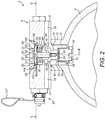
Figure 2 shows a vertical section along line A-A ofFigure 1 ; -
Figure 3 shows vertical cross section through the inflation valve, corresponding to that ofFigure 2 , but with the puncturing needle in an extended position; -
Figure 4 shows a horizontal cross section along line C-C ofFigure 2 ; and -
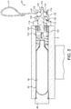
Figure 5 shows a section along line B-B ofFigure 1 . - With reference to
Figure 1 , aninflation device 2 in accordance with the disclosure comprises a source of inflatinggas 4 and aninflation valve 6 mounted to the source of inflatinggas 2. In the embodiment illustrated, the source of inflating gas is a cylinder containing pressurised gas, for example carbon dioxide. Theinflation valve 4 selectively communicates inflation gas from thecylinder 4 to a device (not shown) to be inflated. - As can be seen from
Figure 2 , theinflation valve 6 comprises avalve body 8 which in this embodiment is mounted to aneck portion 10 of the inflatinggas cylinder 2 by means of a threadedconnection 12. - The
valve body 8 comprises aninlet passage 14 having aninlet 15 for fluid communication with thecylinder 4, and at least oneoutlet passage 16 having anoutlet 17, in this embodiment, twooutlet passages 16, for fluid communication with the device to be inflated. In some embodiments, theoutlet passages 16 may be connected to the device through respective pipes (not shown) or they may simply exhaust directly into the device. For example in some embodiments, theoutlet passages 16 may be threaded for connection to hoses or other pipes conducting the inflation gas to the device. Also, while twooutlet passages 16 are shown, one of theoutlet passages 16 may be plugged to provide just a single outlet for inflation gas. - The
inlet passage 14 and theoutlet passages 16 are fluidly connected bypassages 18 defined within thevalve housing 8 as will be described further below. - A
rupturable membrane 20, for example a metallic disc, is arranged in theinlet passage 14 between theinlet 15 and the at least oneoutlet passage 16. In this embodiment, therupturable membrane 20 is received on ashoulder 22 of theinlet passage 14 and retained in position on theshoulder 22 by an externally threadedannular retainer 24 which engages an internally threadedportion 26 of theinlet passage 14. Aseal 28, for example an O-ring seal 28, may be received between theshoulder 22 and therupturable membrane 20. - The
inflation valve 4 further comprises a membrane puncturingelement 30. In the illustrated embodiment, the membrane puncturingelement 30 is a hollow needle, but in other embodiments, the membrane puncturingelement 30 may be a pin, spike or the like. The membrane puncturingelement 30 is, as will be described further below, arranged for movement between a retracted, inoperative position and an extended position in which it punctures therupturable membrane 20. - The membrane puncturing
element 30 is coupled to an actuatingpiston 32 by means of ashaft 34. The actuatingpiston 32 is received in apiston bore 36 defined in thevalve housing 8. A seal, for example an O-ring seal 33 may be provided around the head of thepiston 32 to improve sealing of thepiston 32 within thepiston bore 36. Thepiston shaft 34 extends through aguide channel 38 which opens into an enlargeddiameter bore section 40 of theinlet passage 14. Thepassages 18 extend between thebore section 40 and the closed ends of theoutlet passages 16. - The
piston 32 is urged upwardly, away from therupturable membrane 20, by means of abiasing member 42, in this embodiment acoil spring 42. Oneend 44 of thespring 42 may, as shown, be located in anannular groove 46 formed in an upwardly facing surface 48 of thepiston bore 36. Theother end 50 of thespring 42 may, as shown, be received within arecess 52 formed in the lower face 54 of the actuatingpiston 32. - The upper surface 56 of the actuating
piston 32 is, in this embodiment, domed or crowned, i.e. its central region 58 is raised relative to itsperipheral region 60. Thus, as shown, the upper surface 56 may in certain embodiments be generally frustoconical in shape. In other embodiments, the upper surface 56 may be curved or stepped for example. - The
piston bore 36 is closed at its upper end 62 by aplug 64. The upper end 62 of the piston bore 36 and the plug may be threaded, as shown. Aseal ring 66 may also be provided, as shown, between the piston bore 36 and theplug 64. Thelower surface 68 of theplug 64 is generally planar. - In the retracted position of the membrane puncturing needle illustrated in
Figure 2 , theactuating piston 32 is biased into contact with thelower face 68 of theplug 64. The effect of the crowning of the upper surface 56 of theactuating piston 32 is that it creates an annular chamber 70 between the upper surface 56 of theactuating piston 32 and thelower surface 68 of theplug 64. This chamber 70 has a maximum height at its periphery, becoming shallower towards the axis B of theactuating piston 32. - Turning now to
Figure 4 , thevalve body 8 further comprises an actuating gascartridge receiving chamber 80. In this embodiment, the actuatinggas receiving chamber 80 is arranged with its longitudinal axis A transversely to the axis B of theactuating piston 32, in particular perpendicular thereto. In other embodiments, however, the actuating gascartridge receiving chamber 80 may be arranged such that its axis A is arranged at another orientation relative to the actuating piston axis B, for example generally parallel thereto. - The actuating gas
cartridge receiving chamber 80 receives anactuating gas cartridge 82. Thiscartridge 82 may be a carbon dioxide cartridge, for example. Such cartridges, which may comply with standard SAE AS6011, are widely used in inflating devices such as life jackets and are sealed cartridges containing a known mass of gas at a known pressure. For example, the cartridge may be a Type II, 12 gram capacity carbon dioxide bullet. - One
end 84 of the actuatinggas receiving chamber 80 is closed by aremovable plug 86, which allows insertion of theactuating gas cylinder 82 into the actuatinggas receiving chamber 80. The other end 88 of the actuatinggas receiving chamber 80 is closed by an actuating gascartridge puncturing device 90 which will be discussed further below. The actuatinggas cartridge 82 is biased towards theplug 86 by aspring 92 acting on acollar 94 which engages around theneck 96 of theactuating gas cartridge 82. - An actuating
gas flow passage 100 is formed through thevalve body 8 for communicating actuating gas released from the actuatinggas cartridge 82 to the actuating piston bore 36 upon puncturing theactuating gas cartridge 82, so as to move theactuating piston 32 to move the membranepuncturing element needle 30 from its retracted to its extended position. - The actuating
gas flow passage 100 comprises anannular plenum 102 formed around the actuating piston bore 36 and a connecting passage 104 extending between theannular plenum 102 and the actuatinggas receiving chamber 80. As can best be seen inFigure 3 , at least one, in this embodiment ten, feedpassages 106 extend from theannular plenum 102 to the piston bore 36. Thefeed passages 106 may be circumferentially spaced around the piston bore 36. In this embodiment, thefeed passages 106 are circumferentially equi-spaced around the piston bore 36. An advantage of this particular arrangement is that it allows actuating gas to be evenly distributed about the entire periphery of theactuating piston 32, thereby reducing out of axis forces on theactuating piston 32. In some embodiments, the sum of the cross-section surfaces area of the feed passages shall be not smaller than that of the actuatinggas flow passage 100. This helps avoid or mitigates a reduction in the pressure or flow rate of gas into the annular chamber 70. - As can be seem from
Figure 2 , thefeed passages 106 enter the piston bore 36 at the annular chamber 70 adjacent the upper end 62 of the piston bore.36. - As discussed above, one end 88 of the actuating
gas receiving chamber 80 is closed by an actuating gascartridge puncturing device 90. Details of this actuating gascartridge puncturing device 90 can be seen inFigures 4 and5 . - In this embodiment, the actuating gas
cartridge puncturing device 90 comprises a cartridge puncturing element, for example aneedle 110 mounted on arod 112 having anannular groove 114 formed at anend 116 opposite thecartridge puncturing needle 110. Therod 112 is mounted in anelement 118 mounted, for example threadedly mounted, in the end 88 of the actuatinggas receiving chamber 80. - The
element 118 receives aguide sleeve 120 for guiding therod 112. Therod 112 has anannular flange 122, and acoil spring 124 is mounted between theflange 122 and theguide sleeve 120 so as to bias the puncturingneedle 110 towards the top of theactuating gas cartridge 82. Thecartridge puncturing needle 110 is retained in an unextended position by means of a retainingelement 126 attached to astrap 127 and engaging in theannular groove 114 in therod 112. - The retaining
element 126 is generally spherical in shape and is received in ahousing 128 mounted to theguide sleeve 120. Thehousing 128 comprises awall 130 having anopening 132 for receiving the retainingelement 126. The retainingelement 126 is retained, under the biasing force of thespring 124, between an end of theguide sleeve 120 and awasher 134 which is attached to theend 116 of therod 112 by means of a circlip 138. Thewasher 134 is dished, as can be seen most clearly inFigure 5 . This dishing resists the removal of the retainingelement 126 from thehousing 128 such that the use will have to apply a predetermined force to thestrap 127 to release the retainingelement 126. - Having described the structure of the
inflation valve 6, its mode of operation will now be described. - In the normal, unoperated condition illustrated in
Figures 1 ,2 ,4 and5 , thecartridge puncturing needle 110 and themembrane puncturing needle 30 are retracted by virtue of their respective biasing springs 124, 42. When it is desired to inflate the device, thestrap 127 is pulled, thereby removing the retainingelement 126 from thevalve 6. This in turn releases thecartridge puncturing needle 110, which moves under the force of its biasingspring 124 to puncture the tip of theactuating gas cartridge 82. - This releases actuating gas from the actuating
gas cartridge 82 which then flows through theflow passage 100 to enter the annular chamber 70 formed at the top of the piston bore 36. The pressure of the actuating gas is sufficiently high to move theactuating piston 32 downwardly against the force of thespring 42, thereby causing themembrane puncturing element 30 to move downwardly and puncture themembrane 20. Inflating gas can then flow from thecylinder 4 through theinlet passage 14 to theoutlet passages 16 of thevalve 6 and from there to the device to be inflated. - The use of an
actuating gas cartridge 82 rather than a spring to operate amembrane puncturing element 30 in embodiments of the disclosure is advantageous in that the operation of the needle is not subject to spring relaxation. As a sealed cartridge is used, a reliable, consistent operating pressure will be produced, providing a reliable, consistent movement of themembrane puncturing element 30. The device is thus essentially maintenance free. - The
valve body 8 may be made in a number of ways. In some embodiments, thevalve body 8 may be made by an additive manufacturing technique. This is advantageous as it will allow small, intricately shaped passages, such as thefeed passage 106 to be formed through thevalve body 8. Small passages may allow a low pressure drop between the inflatinggas cartridge 82 and the piston bore 36. In other embodiments, thevalve body 8 may be machined from a single piece of material or assembled from a number of discrete components. - It will be understood that modifications may be made to the exemplary embodiment described above without departing from the scope of the disclosure.
- In some embodiments, for example, the
flow passage 100 may be simplified, and asingle flow passage 100 may enter the piston bore 36, rather than a plurality offeed passages 106. There may be more orfewer feed passages 106 than those illustrated. - Also, other actuating gas
cartridge puncturing devices 90 may be envisaged. For example, a fixed actuating gas cartridge puncturing needle may be provided and thecartridge 82 may be movable within the actuating gascartridge receiving chamber 80 into contact with the puncturing needle. In other embodiments, the actuating gascartridge puncturing device 90 may be moved by hand or by an electromagnetic element such as a solenoid. - Also, while the disclosure has been described in connection with inflation devices, the mechanism valve disclosed could be used in other applications where release of a high pressure gas from a source is required. This applies not only to situations where a source of gas is provided for a specific purpose such as for inflating devices as discussed above, but in other systems where a rapid depressurisation of a space is required. In that event, the
valve 6 may be installed in a wall or outlet of a space, the puncturing of themembrane 30 releasing gas from the space.
Claims (15)
- A valve (6) comprising:a valve body (8) comprising an inlet (15) for fluid communication with a space or source (4) containing pressurised gas, and at least one outlet (17);a membrane (20) arranged between the inlet (15) and the at least one outlet (17);a membrane puncturing element (30) arranged for movement between a retracted, inoperative position and an extended position in which it punctures the membrane (20);an actuating piston (32) operatively coupled to the membrane puncturing element (30) for moving the membrane puncturing element (30) between its retracted and its extended positions, the actuating piston (32) being received in a piston bore (36) of the valve body (8);a cartridge receiving chamber (80) for receiving a sealed actuating gas cartridge (82);a cartridge puncturing device (90) for puncturing the actuating gas cartridge (82); andan actuating gas flow passage (100) for communicating actuating gas released from the actuating gas cartridge (82) to the actuating piston bore (36) upon puncturing the actuating gas cartridge (82) for moving the actuating piston (32) and thus the membrane puncturing element (30) from its retracted to its extended position.
- A valve as claimed in claim 1, wherein the actuating gas flow passage (100) comprises an annular plenum (102) extending around the axis of the actuating piston bore (36) and at least one feed passage (106) extending from the annular plenum (100) to the actuating piston bore (36).
- A valve as claimed in claim 2, comprising a plurality of feed passages (102) circumferentially spaced around the axis (B) of the actuating piston bore (36).
- A valve as claimed in claim 3, wherein the plurality of feed passages (102) are circumferentially equi-spaced around the axis (B) of the actuating piston bore (36).
- A valve as claimed in any preceding claim, wherein the actuating piston (36) is biased into contact with an end (62) of the actuating piston bore (36) by a biasing spring (42).
- A valve as claimed in any preceding claim, wherein the actuating gas flow passage (100) enters the actuating piston bore (36) adjacent one end (62) thereof.
- A valve as claimed in any preceding claim, wherein the face of the actuating piston (32) facing the end of the actuating piston bore (36) is crowned so as to form an annular chamber (70) between the actuating piston (32) and the end of the actuating piston bore (36), the actuating gas flow passage (100) being connected to the annular chamber (70).
- A valve as claimed in claim 5, 6 or 7, wherein the end (62) of the actuating piston bore (36) is formed by a plug (64) mounted within an opening of the valve body (8),
- A valve as claimed in any preceding claim, wherein the cartridge receiving chamber (80) is arranged transversely to the axis (B) of the actuating piston (32).
- A valve as claimed in any preceding claim, wherein the valve body (8) is additively manufactured.
- A valve as claimed in any preceding claim, wherein the actuating gas cartridge puncturing device (90) comprises a spring loaded needle (110).
- A valve as claimed in any preceding claim, further comprising an actuating gas cartridge (82) arranged in the cartridge receiving chamber (80).
- A valve as claimed in claim 12, wherein the actuating gas is carbon dioxide.
- An inflation device (2) comprising a valve (6) as claimed in any preceding claim and a source (4) of inflating gas, for example a cylinder (4) of inflating gas, coupled to the inlet (14) of the valve (6).
- A method of inflating an inflatable device comprising:puncturing a membrane (20) arranged in a flow path between a source (4) of inflating gas and the inflatable device by moving a membrane puncturing element (30) from a retracted, inoperative position, to an extended, rupturing position, the movement of the membrane puncturing element (30) to the extended position being effected by releasing actuating gas from an actuating gas cartridge (82) into an actuation piston bore (36) which receives an actuating piston (32) to which the membrane puncturing element (30) is operatively coupled.
Priority Applications (2)
| Application Number | Priority Date | Filing Date | Title |
|---|---|---|---|
| EP18461610.0A EP3627034B1 (en) | 2018-09-21 | 2018-09-21 | Valve |
| US16/560,076 US11060624B2 (en) | 2018-09-21 | 2019-09-04 | Valve |
Applications Claiming Priority (1)
| Application Number | Priority Date | Filing Date | Title |
|---|---|---|---|
| EP18461610.0A EP3627034B1 (en) | 2018-09-21 | 2018-09-21 | Valve |
Publications (2)
| Publication Number | Publication Date |
|---|---|
| EP3627034A1 true EP3627034A1 (en) | 2020-03-25 |
| EP3627034B1 EP3627034B1 (en) | 2021-10-27 |
Family
ID=63678593
Family Applications (1)
| Application Number | Title | Priority Date | Filing Date |
|---|---|---|---|
| EP18461610.0A Active EP3627034B1 (en) | 2018-09-21 | 2018-09-21 | Valve |
Country Status (2)
| Country | Link |
|---|---|
| US (1) | US11060624B2 (en) |
| EP (1) | EP3627034B1 (en) |
Cited By (1)
| Publication number | Priority date | Publication date | Assignee | Title |
|---|---|---|---|---|
| US11274754B2 (en) | 2018-12-17 | 2022-03-15 | Goodrich Corporation | Membrane puncturing mechanism |
Families Citing this family (6)
| Publication number | Priority date | Publication date | Assignee | Title |
|---|---|---|---|---|
| US12013043B2 (en) | 2020-12-21 | 2024-06-18 | Xerox Corporation | Triggerable mechanisms and fragment containment arrangements for self-destructing frangible structures and sealed vessels |
| US11904986B2 (en) * | 2020-12-21 | 2024-02-20 | Xerox Corporation | Mechanical triggers and triggering methods for self-destructing frangible structures and sealed vessels |
| GB2613602B (en) * | 2021-12-08 | 2024-11-13 | Leafield Marine Ltd | A release valve |
| US12297926B2 (en) | 2022-05-20 | 2025-05-13 | Goodrich Corporation | Solenoid operated pressure cartridge for inflation system |
| EP4310384B1 (en) * | 2022-07-22 | 2025-12-03 | Goodrich Corporation | Magneto strictive actuated pressure regulator module for inflation system |
| US12203600B2 (en) | 2022-07-22 | 2025-01-21 | Goodrich Corporation | Magneto strictive actuated pressure regulator module for inflation system |
Citations (9)
| Publication number | Priority date | Publication date | Assignee | Title |
|---|---|---|---|---|
| US4083187A (en) * | 1975-12-09 | 1978-04-11 | Tokico Ltd. | Actuator for emergency operation |
| US4500014A (en) * | 1982-12-14 | 1985-02-19 | Halkey-Roberts Corp. | Multiple firing inflator |
| EP0155407A2 (en) * | 1984-03-02 | 1985-09-25 | Pewa Technic Ag | Gas supply device having a plurality of gas cartridges inside a pressurised-gas container |
| WO1996002420A1 (en) * | 1994-07-14 | 1996-02-01 | Reebok International Ltd. | Inflation system utilizing a gas inflation device |
| US5653191A (en) * | 1994-03-01 | 1997-08-05 | Calhoun; Clifford A. | Pressure indicator |
| US6123227A (en) * | 1998-10-27 | 2000-09-26 | Safety Co., Ltd. | Gas generating apparatus for emergency refuge implements |
| US6260570B1 (en) | 1997-06-16 | 2001-07-17 | Lloyd G. Wass | Puncture disc raft inflation valve having a one-piece valve body |
| US7703640B1 (en) * | 2006-02-01 | 2010-04-27 | Anthony Scott Hollars | Heat actuated puncturing mechanism for a compressed gas cartridge |
| US20150166155A1 (en) * | 2013-12-17 | 2015-06-18 | STARJET Technologies Co., Ltd | Short-range lifebuoy launcher |
Family Cites Families (20)
| Publication number | Priority date | Publication date | Assignee | Title |
|---|---|---|---|---|
| US2653602A (en) * | 1950-06-17 | 1953-09-29 | Becton Dickinson Co | Injection device |
| US3017907A (en) * | 1959-09-30 | 1962-01-23 | Specialties Dev Corp | Inflation equipment |
| US3127624A (en) * | 1961-06-19 | 1964-04-07 | Ted J Kubit | Automatically-inflatable life preserver |
| US4024440A (en) * | 1975-02-13 | 1977-05-17 | Conax Corporation | Water activated pressurized gas release device |
| US4498605A (en) * | 1982-07-29 | 1985-02-12 | Halkey-Roberts Corporation | Automatic inflator |
| US4482081A (en) * | 1982-09-30 | 1984-11-13 | Gulf & Western Manufacturing Company | Water activated inflation mechanism |
| US4687451A (en) * | 1985-11-04 | 1987-08-18 | Chen Tsung H | Automatic actuation device for inflatable life-saving equipment |
| US4768128A (en) * | 1986-01-08 | 1988-08-30 | Conax Florida Corporation | Water activated pressurized gas release device |
| US4887591A (en) * | 1988-07-27 | 1989-12-19 | Grace Create Inc. | Midget life-saving respirator gas tank apparatus |
| US5064413A (en) * | 1989-11-09 | 1991-11-12 | Bioject, Inc. | Needleless hypodermic injection device |
| US5026310A (en) * | 1990-02-28 | 1991-06-25 | Halkey-Roberts Corporation | Electric autoinflator |
| US20010004682A1 (en) * | 1995-12-16 | 2001-06-21 | Weston Medical Ltd. | Needleless injector drug capsule |
| US5643030A (en) * | 1996-07-17 | 1997-07-01 | Brown; Dennis | Gas cartridge safety inflator apparatus |
| US6089403A (en) | 1997-11-25 | 2000-07-18 | Mackal; Glenn H. | Inflation system with pneumatic assist |
| CA2465502C (en) * | 2001-11-09 | 2011-03-22 | Pedro De La Serna | Pneumatic powered autoinjector |
| US7547293B2 (en) * | 2006-10-06 | 2009-06-16 | Bioject, Inc. | Triggering mechanism for needle-free injector |
| US9458935B2 (en) * | 2006-10-06 | 2016-10-04 | Helmut Fricke | Lockable joint |
| US7744563B2 (en) * | 2007-02-23 | 2010-06-29 | Bioject, Inc. | Needle-free injection devices and drug delivery systems therefor |
| US9601222B2 (en) * | 2009-12-02 | 2017-03-21 | GE-Hitachi Nuclear Energy Americans LLC | Emergency fluid source for harsh environments |
| WO2014018332A1 (en) * | 2012-07-23 | 2014-01-30 | Carleton Technologies, Inc. | Inflator assembly adapted for manual or automatic inflation |
-
2018
- 2018-09-21 EP EP18461610.0A patent/EP3627034B1/en active Active
-
2019
- 2019-09-04 US US16/560,076 patent/US11060624B2/en active Active
Patent Citations (10)
| Publication number | Priority date | Publication date | Assignee | Title |
|---|---|---|---|---|
| US4083187A (en) * | 1975-12-09 | 1978-04-11 | Tokico Ltd. | Actuator for emergency operation |
| US4500014A (en) * | 1982-12-14 | 1985-02-19 | Halkey-Roberts Corp. | Multiple firing inflator |
| EP0155407A2 (en) * | 1984-03-02 | 1985-09-25 | Pewa Technic Ag | Gas supply device having a plurality of gas cartridges inside a pressurised-gas container |
| US4606384A (en) * | 1984-03-02 | 1986-08-19 | Pewa Technic Ag | Gas supply device including a plurality of gas flasks inserted in a pressurized gas container |
| US5653191A (en) * | 1994-03-01 | 1997-08-05 | Calhoun; Clifford A. | Pressure indicator |
| WO1996002420A1 (en) * | 1994-07-14 | 1996-02-01 | Reebok International Ltd. | Inflation system utilizing a gas inflation device |
| US6260570B1 (en) | 1997-06-16 | 2001-07-17 | Lloyd G. Wass | Puncture disc raft inflation valve having a one-piece valve body |
| US6123227A (en) * | 1998-10-27 | 2000-09-26 | Safety Co., Ltd. | Gas generating apparatus for emergency refuge implements |
| US7703640B1 (en) * | 2006-02-01 | 2010-04-27 | Anthony Scott Hollars | Heat actuated puncturing mechanism for a compressed gas cartridge |
| US20150166155A1 (en) * | 2013-12-17 | 2015-06-18 | STARJET Technologies Co., Ltd | Short-range lifebuoy launcher |
Cited By (2)
| Publication number | Priority date | Publication date | Assignee | Title |
|---|---|---|---|---|
| US11274754B2 (en) | 2018-12-17 | 2022-03-15 | Goodrich Corporation | Membrane puncturing mechanism |
| EP3670981B1 (en) * | 2018-12-17 | 2023-12-06 | Goodrich Corporation | Membrane puncturing mechanism |
Also Published As
| Publication number | Publication date |
|---|---|
| EP3627034B1 (en) | 2021-10-27 |
| US20200096123A1 (en) | 2020-03-26 |
| US11060624B2 (en) | 2021-07-13 |
Similar Documents
| Publication | Publication Date | Title |
|---|---|---|
| EP3627034B1 (en) | Valve | |
| US6321770B1 (en) | Regulator valve for escape slide | |
| CN102224365A (en) | Impulse actuated valve | |
| US11886212B2 (en) | Pneumatic valve with rupturable membrane | |
| US10914396B2 (en) | Electro-pneumatic valve with pressurized container | |
| EP0134447B1 (en) | Valve for high pressure fluid container | |
| US20100163763A1 (en) | Pilot operated vacuum packable inflation system | |
| US7481241B2 (en) | Method and apparatus for a pressure regulator | |
| US8776820B2 (en) | High rate discharge (HRD) valve incorporating a collet sleeve release mechanism | |
| US8800585B2 (en) | High rate discharge (HRD) valve incorporating a rotating lever release mechanism | |
| US20150166155A1 (en) | Short-range lifebuoy launcher | |
| US7299816B2 (en) | Inflation valve assembly | |
| US5921832A (en) | Inflation valve | |
| US12523344B2 (en) | Release valve | |
| KR101632688B1 (en) | Reducing Valve of Hyperbaric Gas Can | |
| EP3611414B1 (en) | Trigger mechanism for a valve assembly | |
| US9062780B2 (en) | Pressure regulator with slide-mount lobes | |
| HK1159730B (en) | Impulse actuated valve | |
| AU2012261479A1 (en) | High rate discharge (HRD) valve incorporating a collect sleeve release mechanism |
Legal Events
| Date | Code | Title | Description |
|---|---|---|---|
| PUAI | Public reference made under article 153(3) epc to a published international application that has entered the european phase |
Free format text: ORIGINAL CODE: 0009012 |
|
| STAA | Information on the status of an ep patent application or granted ep patent |
Free format text: STATUS: THE APPLICATION HAS BEEN PUBLISHED |
|
| AK | Designated contracting states |
Kind code of ref document: A1 Designated state(s): AL AT BE BG CH CY CZ DE DK EE ES FI FR GB GR HR HU IE IS IT LI LT LU LV MC MK MT NL NO PL PT RO RS SE SI SK SM TR |
|
| AX | Request for extension of the european patent |
Extension state: BA ME |
|
| STAA | Information on the status of an ep patent application or granted ep patent |
Free format text: STATUS: REQUEST FOR EXAMINATION WAS MADE |
|
| 17P | Request for examination filed |
Effective date: 20200925 |
|
| RBV | Designated contracting states (corrected) |
Designated state(s): AL AT BE BG CH CY CZ DE DK EE ES FI FR GB GR HR HU IE IS IT LI LT LU LV MC MK MT NL NO PL PT RO RS SE SI SK SM TR |
|
| REG | Reference to a national code |
Ref country code: DE Ref legal event code: R079 Ref document number: 602018025641 Country of ref document: DE Free format text: PREVIOUS MAIN CLASS: F17C0013040000 Ipc: F17C0013060000 |
|
| RIC1 | Information provided on ipc code assigned before grant |
Ipc: F17C 13/06 20060101AFI20210129BHEP Ipc: B64D 25/14 20060101ALI20210129BHEP Ipc: F16K 17/40 20060101ALI20210129BHEP Ipc: F16K 31/122 20060101ALI20210129BHEP |
|
| GRAP | Despatch of communication of intention to grant a patent |
Free format text: ORIGINAL CODE: EPIDOSNIGR1 |
|
| STAA | Information on the status of an ep patent application or granted ep patent |
Free format text: STATUS: GRANT OF PATENT IS INTENDED |
|
| INTG | Intention to grant announced |
Effective date: 20210330 |
|
| GRAS | Grant fee paid |
Free format text: ORIGINAL CODE: EPIDOSNIGR3 |
|
| GRAA | (expected) grant |
Free format text: ORIGINAL CODE: 0009210 |
|
| STAA | Information on the status of an ep patent application or granted ep patent |
Free format text: STATUS: THE PATENT HAS BEEN GRANTED |
|
| AK | Designated contracting states |
Kind code of ref document: B1 Designated state(s): AL AT BE BG CH CY CZ DE DK EE ES FI FR GB GR HR HU IE IS IT LI LT LU LV MC MK MT NL NO PL PT RO RS SE SI SK SM TR |
|
| REG | Reference to a national code |
Ref country code: GB Ref legal event code: FG4D |
|
| REG | Reference to a national code |
Ref country code: CH Ref legal event code: EP |
|
| REG | Reference to a national code |
Ref country code: AT Ref legal event code: REF Ref document number: 1442098 Country of ref document: AT Kind code of ref document: T Effective date: 20211115 |
|
| REG | Reference to a national code |
Ref country code: DE Ref legal event code: R096 Ref document number: 602018025641 Country of ref document: DE |
|
| REG | Reference to a national code |
Ref country code: IE Ref legal event code: FG4D |
|
| REG | Reference to a national code |
Ref country code: LT Ref legal event code: MG9D |
|
| REG | Reference to a national code |
Ref country code: NL Ref legal event code: MP Effective date: 20211027 |
|
| REG | Reference to a national code |
Ref country code: AT Ref legal event code: MK05 Ref document number: 1442098 Country of ref document: AT Kind code of ref document: T Effective date: 20211027 |
|
| PG25 | Lapsed in a contracting state [announced via postgrant information from national office to epo] |
Ref country code: RS Free format text: LAPSE BECAUSE OF FAILURE TO SUBMIT A TRANSLATION OF THE DESCRIPTION OR TO PAY THE FEE WITHIN THE PRESCRIBED TIME-LIMIT Effective date: 20211027 Ref country code: LT Free format text: LAPSE BECAUSE OF FAILURE TO SUBMIT A TRANSLATION OF THE DESCRIPTION OR TO PAY THE FEE WITHIN THE PRESCRIBED TIME-LIMIT Effective date: 20211027 Ref country code: FI Free format text: LAPSE BECAUSE OF FAILURE TO SUBMIT A TRANSLATION OF THE DESCRIPTION OR TO PAY THE FEE WITHIN THE PRESCRIBED TIME-LIMIT Effective date: 20211027 Ref country code: BG Free format text: LAPSE BECAUSE OF FAILURE TO SUBMIT A TRANSLATION OF THE DESCRIPTION OR TO PAY THE FEE WITHIN THE PRESCRIBED TIME-LIMIT Effective date: 20220127 Ref country code: AT Free format text: LAPSE BECAUSE OF FAILURE TO SUBMIT A TRANSLATION OF THE DESCRIPTION OR TO PAY THE FEE WITHIN THE PRESCRIBED TIME-LIMIT Effective date: 20211027 |
|
| PG25 | Lapsed in a contracting state [announced via postgrant information from national office to epo] |
Ref country code: IS Free format text: LAPSE BECAUSE OF FAILURE TO SUBMIT A TRANSLATION OF THE DESCRIPTION OR TO PAY THE FEE WITHIN THE PRESCRIBED TIME-LIMIT Effective date: 20220227 Ref country code: SE Free format text: LAPSE BECAUSE OF FAILURE TO SUBMIT A TRANSLATION OF THE DESCRIPTION OR TO PAY THE FEE WITHIN THE PRESCRIBED TIME-LIMIT Effective date: 20211027 Ref country code: PT Free format text: LAPSE BECAUSE OF FAILURE TO SUBMIT A TRANSLATION OF THE DESCRIPTION OR TO PAY THE FEE WITHIN THE PRESCRIBED TIME-LIMIT Effective date: 20220228 Ref country code: PL Free format text: LAPSE BECAUSE OF FAILURE TO SUBMIT A TRANSLATION OF THE DESCRIPTION OR TO PAY THE FEE WITHIN THE PRESCRIBED TIME-LIMIT Effective date: 20211027 Ref country code: NO Free format text: LAPSE BECAUSE OF FAILURE TO SUBMIT A TRANSLATION OF THE DESCRIPTION OR TO PAY THE FEE WITHIN THE PRESCRIBED TIME-LIMIT Effective date: 20220127 Ref country code: NL Free format text: LAPSE BECAUSE OF FAILURE TO SUBMIT A TRANSLATION OF THE DESCRIPTION OR TO PAY THE FEE WITHIN THE PRESCRIBED TIME-LIMIT Effective date: 20211027 Ref country code: LV Free format text: LAPSE BECAUSE OF FAILURE TO SUBMIT A TRANSLATION OF THE DESCRIPTION OR TO PAY THE FEE WITHIN THE PRESCRIBED TIME-LIMIT Effective date: 20211027 Ref country code: HR Free format text: LAPSE BECAUSE OF FAILURE TO SUBMIT A TRANSLATION OF THE DESCRIPTION OR TO PAY THE FEE WITHIN THE PRESCRIBED TIME-LIMIT Effective date: 20211027 Ref country code: GR Free format text: LAPSE BECAUSE OF FAILURE TO SUBMIT A TRANSLATION OF THE DESCRIPTION OR TO PAY THE FEE WITHIN THE PRESCRIBED TIME-LIMIT Effective date: 20220128 Ref country code: ES Free format text: LAPSE BECAUSE OF FAILURE TO SUBMIT A TRANSLATION OF THE DESCRIPTION OR TO PAY THE FEE WITHIN THE PRESCRIBED TIME-LIMIT Effective date: 20211027 |
|
| REG | Reference to a national code |
Ref country code: DE Ref legal event code: R097 Ref document number: 602018025641 Country of ref document: DE |
|
| PG25 | Lapsed in a contracting state [announced via postgrant information from national office to epo] |
Ref country code: SM Free format text: LAPSE BECAUSE OF FAILURE TO SUBMIT A TRANSLATION OF THE DESCRIPTION OR TO PAY THE FEE WITHIN THE PRESCRIBED TIME-LIMIT Effective date: 20211027 Ref country code: SK Free format text: LAPSE BECAUSE OF FAILURE TO SUBMIT A TRANSLATION OF THE DESCRIPTION OR TO PAY THE FEE WITHIN THE PRESCRIBED TIME-LIMIT Effective date: 20211027 Ref country code: RO Free format text: LAPSE BECAUSE OF FAILURE TO SUBMIT A TRANSLATION OF THE DESCRIPTION OR TO PAY THE FEE WITHIN THE PRESCRIBED TIME-LIMIT Effective date: 20211027 Ref country code: EE Free format text: LAPSE BECAUSE OF FAILURE TO SUBMIT A TRANSLATION OF THE DESCRIPTION OR TO PAY THE FEE WITHIN THE PRESCRIBED TIME-LIMIT Effective date: 20211027 Ref country code: DK Free format text: LAPSE BECAUSE OF FAILURE TO SUBMIT A TRANSLATION OF THE DESCRIPTION OR TO PAY THE FEE WITHIN THE PRESCRIBED TIME-LIMIT Effective date: 20211027 Ref country code: CZ Free format text: LAPSE BECAUSE OF FAILURE TO SUBMIT A TRANSLATION OF THE DESCRIPTION OR TO PAY THE FEE WITHIN THE PRESCRIBED TIME-LIMIT Effective date: 20211027 |
|
| PLBE | No opposition filed within time limit |
Free format text: ORIGINAL CODE: 0009261 |
|
| STAA | Information on the status of an ep patent application or granted ep patent |
Free format text: STATUS: NO OPPOSITION FILED WITHIN TIME LIMIT |
|
| 26N | No opposition filed |
Effective date: 20220728 |
|
| PG25 | Lapsed in a contracting state [announced via postgrant information from national office to epo] |
Ref country code: AL Free format text: LAPSE BECAUSE OF FAILURE TO SUBMIT A TRANSLATION OF THE DESCRIPTION OR TO PAY THE FEE WITHIN THE PRESCRIBED TIME-LIMIT Effective date: 20211027 |
|
| PG25 | Lapsed in a contracting state [announced via postgrant information from national office to epo] |
Ref country code: SI Free format text: LAPSE BECAUSE OF FAILURE TO SUBMIT A TRANSLATION OF THE DESCRIPTION OR TO PAY THE FEE WITHIN THE PRESCRIBED TIME-LIMIT Effective date: 20211027 |
|
| PG25 | Lapsed in a contracting state [announced via postgrant information from national office to epo] |
Ref country code: MC Free format text: LAPSE BECAUSE OF FAILURE TO SUBMIT A TRANSLATION OF THE DESCRIPTION OR TO PAY THE FEE WITHIN THE PRESCRIBED TIME-LIMIT Effective date: 20211027 |
|
| REG | Reference to a national code |
Ref country code: CH Ref legal event code: PL |
|
| REG | Reference to a national code |
Ref country code: BE Ref legal event code: MM Effective date: 20220930 |
|
| PG25 | Lapsed in a contracting state [announced via postgrant information from national office to epo] |
Ref country code: IT Free format text: LAPSE BECAUSE OF FAILURE TO SUBMIT A TRANSLATION OF THE DESCRIPTION OR TO PAY THE FEE WITHIN THE PRESCRIBED TIME-LIMIT Effective date: 20211027 |
|
| P01 | Opt-out of the competence of the unified patent court (upc) registered |
Effective date: 20230521 |
|
| PG25 | Lapsed in a contracting state [announced via postgrant information from national office to epo] |
Ref country code: LU Free format text: LAPSE BECAUSE OF NON-PAYMENT OF DUE FEES Effective date: 20220921 |
|
| PG25 | Lapsed in a contracting state [announced via postgrant information from national office to epo] |
Ref country code: IE Free format text: LAPSE BECAUSE OF NON-PAYMENT OF DUE FEES Effective date: 20220921 Ref country code: CH Free format text: LAPSE BECAUSE OF NON-PAYMENT OF DUE FEES Effective date: 20220930 Ref country code: LI Free format text: LAPSE BECAUSE OF NON-PAYMENT OF DUE FEES Effective date: 20220930 |
|
| PG25 | Lapsed in a contracting state [announced via postgrant information from national office to epo] |
Ref country code: BE Free format text: LAPSE BECAUSE OF NON-PAYMENT OF DUE FEES Effective date: 20220930 |
|
| PG25 | Lapsed in a contracting state [announced via postgrant information from national office to epo] |
Ref country code: HU Free format text: LAPSE BECAUSE OF FAILURE TO SUBMIT A TRANSLATION OF THE DESCRIPTION OR TO PAY THE FEE WITHIN THE PRESCRIBED TIME-LIMIT; INVALID AB INITIO Effective date: 20180921 |
|
| PG25 | Lapsed in a contracting state [announced via postgrant information from national office to epo] |
Ref country code: CY Free format text: LAPSE BECAUSE OF FAILURE TO SUBMIT A TRANSLATION OF THE DESCRIPTION OR TO PAY THE FEE WITHIN THE PRESCRIBED TIME-LIMIT Effective date: 20211027 |
|
| PG25 | Lapsed in a contracting state [announced via postgrant information from national office to epo] |
Ref country code: MK Free format text: LAPSE BECAUSE OF FAILURE TO SUBMIT A TRANSLATION OF THE DESCRIPTION OR TO PAY THE FEE WITHIN THE PRESCRIBED TIME-LIMIT Effective date: 20211027 |
|
| PG25 | Lapsed in a contracting state [announced via postgrant information from national office to epo] |
Ref country code: TR Free format text: LAPSE BECAUSE OF FAILURE TO SUBMIT A TRANSLATION OF THE DESCRIPTION OR TO PAY THE FEE WITHIN THE PRESCRIBED TIME-LIMIT Effective date: 20211027 |
|
| PG25 | Lapsed in a contracting state [announced via postgrant information from national office to epo] |
Ref country code: MT Free format text: LAPSE BECAUSE OF FAILURE TO SUBMIT A TRANSLATION OF THE DESCRIPTION OR TO PAY THE FEE WITHIN THE PRESCRIBED TIME-LIMIT Effective date: 20211027 |
|
| PGFP | Annual fee paid to national office [announced via postgrant information from national office to epo] |
Ref country code: DE Payment date: 20250820 Year of fee payment: 8 |
|
| PGFP | Annual fee paid to national office [announced via postgrant information from national office to epo] |
Ref country code: GB Payment date: 20250822 Year of fee payment: 8 |
|
| PGFP | Annual fee paid to national office [announced via postgrant information from national office to epo] |
Ref country code: FR Payment date: 20250820 Year of fee payment: 8 |